EP3552576B1 - Filter - Google Patents
Filter Download PDFInfo
- Publication number
- EP3552576B1 EP3552576B1 EP17877963.3A EP17877963A EP3552576B1 EP 3552576 B1 EP3552576 B1 EP 3552576B1 EP 17877963 A EP17877963 A EP 17877963A EP 3552576 B1 EP3552576 B1 EP 3552576B1
- Authority
- EP
- European Patent Office
- Prior art keywords
- contour line
- filter
- flexible section
- section
- filter according
- Prior art date
- Legal status (The legal status is an assumption and is not a legal conclusion. Google has not performed a legal analysis and makes no representation as to the accuracy of the status listed.)
- Active
Links
Images


Classifications
-
- A—HUMAN NECESSITIES
- A61—MEDICAL OR VETERINARY SCIENCE; HYGIENE
- A61F—FILTERS IMPLANTABLE INTO BLOOD VESSELS; PROSTHESES; DEVICES PROVIDING PATENCY TO, OR PREVENTING COLLAPSING OF, TUBULAR STRUCTURES OF THE BODY, e.g. STENTS; ORTHOPAEDIC, NURSING OR CONTRACEPTIVE DEVICES; FOMENTATION; TREATMENT OR PROTECTION OF EYES OR EARS; BANDAGES, DRESSINGS OR ABSORBENT PADS; FIRST-AID KITS
- A61F2/00—Filters implantable into blood vessels; Prostheses, i.e. artificial substitutes or replacements for parts of the body; Appliances for connecting them with the body; Devices providing patency to, or preventing collapsing of, tubular structures of the body, e.g. stents
- A61F2/01—Filters implantable into blood vessels
- A61F2/0108—Both ends closed, i.e. legs gathered at both ends
-
- A—HUMAN NECESSITIES
- A61—MEDICAL OR VETERINARY SCIENCE; HYGIENE
- A61F—FILTERS IMPLANTABLE INTO BLOOD VESSELS; PROSTHESES; DEVICES PROVIDING PATENCY TO, OR PREVENTING COLLAPSING OF, TUBULAR STRUCTURES OF THE BODY, e.g. STENTS; ORTHOPAEDIC, NURSING OR CONTRACEPTIVE DEVICES; FOMENTATION; TREATMENT OR PROTECTION OF EYES OR EARS; BANDAGES, DRESSINGS OR ABSORBENT PADS; FIRST-AID KITS
- A61F2/00—Filters implantable into blood vessels; Prostheses, i.e. artificial substitutes or replacements for parts of the body; Appliances for connecting them with the body; Devices providing patency to, or preventing collapsing of, tubular structures of the body, e.g. stents
- A61F2/01—Filters implantable into blood vessels
- A61F2002/016—Filters implantable into blood vessels made from wire-like elements
-
- A—HUMAN NECESSITIES
- A61—MEDICAL OR VETERINARY SCIENCE; HYGIENE
- A61F—FILTERS IMPLANTABLE INTO BLOOD VESSELS; PROSTHESES; DEVICES PROVIDING PATENCY TO, OR PREVENTING COLLAPSING OF, TUBULAR STRUCTURES OF THE BODY, e.g. STENTS; ORTHOPAEDIC, NURSING OR CONTRACEPTIVE DEVICES; FOMENTATION; TREATMENT OR PROTECTION OF EYES OR EARS; BANDAGES, DRESSINGS OR ABSORBENT PADS; FIRST-AID KITS
- A61F2/00—Filters implantable into blood vessels; Prostheses, i.e. artificial substitutes or replacements for parts of the body; Appliances for connecting them with the body; Devices providing patency to, or preventing collapsing of, tubular structures of the body, e.g. stents
- A61F2/01—Filters implantable into blood vessels
- A61F2002/018—Filters implantable into blood vessels made from tubes or sheets of material, e.g. by etching or laser-cutting
-
- A—HUMAN NECESSITIES
- A61—MEDICAL OR VETERINARY SCIENCE; HYGIENE
- A61F—FILTERS IMPLANTABLE INTO BLOOD VESSELS; PROSTHESES; DEVICES PROVIDING PATENCY TO, OR PREVENTING COLLAPSING OF, TUBULAR STRUCTURES OF THE BODY, e.g. STENTS; ORTHOPAEDIC, NURSING OR CONTRACEPTIVE DEVICES; FOMENTATION; TREATMENT OR PROTECTION OF EYES OR EARS; BANDAGES, DRESSINGS OR ABSORBENT PADS; FIRST-AID KITS
- A61F2220/00—Fixations or connections for prostheses classified in groups A61F2/00 - A61F2/26 or A61F2/82 or A61F9/00 or A61F11/00 or subgroups thereof
- A61F2220/0008—Fixation appliances for connecting prostheses to the body
- A61F2220/0016—Fixation appliances for connecting prostheses to the body with sharp anchoring protrusions, e.g. barbs, pins, spikes
-
- A—HUMAN NECESSITIES
- A61—MEDICAL OR VETERINARY SCIENCE; HYGIENE
- A61F—FILTERS IMPLANTABLE INTO BLOOD VESSELS; PROSTHESES; DEVICES PROVIDING PATENCY TO, OR PREVENTING COLLAPSING OF, TUBULAR STRUCTURES OF THE BODY, e.g. STENTS; ORTHOPAEDIC, NURSING OR CONTRACEPTIVE DEVICES; FOMENTATION; TREATMENT OR PROTECTION OF EYES OR EARS; BANDAGES, DRESSINGS OR ABSORBENT PADS; FIRST-AID KITS
- A61F2220/00—Fixations or connections for prostheses classified in groups A61F2/00 - A61F2/26 or A61F2/82 or A61F9/00 or A61F11/00 or subgroups thereof
- A61F2220/0025—Connections or couplings between prosthetic parts, e.g. between modular parts; Connecting elements
-
- A—HUMAN NECESSITIES
- A61—MEDICAL OR VETERINARY SCIENCE; HYGIENE
- A61F—FILTERS IMPLANTABLE INTO BLOOD VESSELS; PROSTHESES; DEVICES PROVIDING PATENCY TO, OR PREVENTING COLLAPSING OF, TUBULAR STRUCTURES OF THE BODY, e.g. STENTS; ORTHOPAEDIC, NURSING OR CONTRACEPTIVE DEVICES; FOMENTATION; TREATMENT OR PROTECTION OF EYES OR EARS; BANDAGES, DRESSINGS OR ABSORBENT PADS; FIRST-AID KITS
- A61F2250/00—Special features of prostheses classified in groups A61F2/00 - A61F2/26 or A61F2/82 or A61F9/00 or A61F11/00 or subgroups thereof
- A61F2250/0014—Special features of prostheses classified in groups A61F2/00 - A61F2/26 or A61F2/82 or A61F9/00 or A61F11/00 or subgroups thereof having different values of a given property or geometrical feature, e.g. mechanical property or material property, at different locations within the same prosthesis
- A61F2250/0018—Special features of prostheses classified in groups A61F2/00 - A61F2/26 or A61F2/82 or A61F9/00 or A61F11/00 or subgroups thereof having different values of a given property or geometrical feature, e.g. mechanical property or material property, at different locations within the same prosthesis differing in elasticity, stiffness or compressibility
Definitions
- the present disclosure relates to a cardiovascular medical device, and more particularly relates to a withdrawable vena cava filter implanted into a blood vessel by means of intervention.
- Pulmonary embolism is a common disease, causing a high mortality rate. According to a statistical data, a mortality rate caused by untreated pulmonary embolism is 20 to 30 percent. Every year, new cases are about 0.2 percent of the population. There are 2,700,000 new cases according to the population of 1.35 billion of China.
- thrombosis are the most common pulmonary emboli.
- factors in the formation of thrombosis including slow venous blood flow and blood stasis, blood stasis, or increase of thrombocyte and blood coagulation factors and enhancement of blood adherence which may all caused by traumatism or bone fracture, trauma, relatively big surgery, extensive burn, gestation, childbirth, being confined to bed by long illness, sedentariness in a long-distance bus or a flight, long-time sitting still and squatting and the like.
- thrombi are generally slightly adhered to a lumen wall and are prone to fall off, and dropped emboli may cause severe lesions such as the pulmonary embolism.
- a venous thrombus may be formed in any part, most commonly in the lower limb.
- a vena cava filter (hereinafter referred to as "filter”) is a safe and effective measure for preventing pulmonary embolism and may reduce a incidence rate of pulmonary embolism.
- filter a vena cava filter
- a filter supporting rod would be climbed and covered by endothelial cells to varying degrees because of stimulation to a blood vessel, so the filter is difficult to take out, and then may only be implanted as a permanent filter for a long time in the human body. And the permanent filter implanted into the human body may cause certain risks.
- the filter is in contact with blood and blood vessel endothelium for a long time, which probably leads to protein adsorption and platelet adhesion and eventually causes thrombosis, and the thrombosis will result in venous blockage or recurrence of pulmonary embolism; and there is a risk that the filter implanted for a long time in the human body may deform, tilt, shift, break or even penetrate the blood vessel, and the like.
- One solution is to form a coating layer for preventing cell growth on the surface of the filter through a surface modification method, so as to prevent an endangium from climbing over the surface of the filter.
- the other solution is a method of structural design, by which the filter has two closed ends and open supporting rods abutting with the blood vessel wall to separate the filter from the blood vessel wall.
- the Chinese patent No. CN102330059B is a typical example of the first solution, which uses the surface modification method to deposit a polyethylene glycol-like thin film on the surface of the filter and makes use of anti-protein and cell adhesion characteristics of polyethylene glycol to inhibit the cell growth on the surface of the filter and prevent endothelial cells from covering the supporting rods, so as to achieve a withdrawability of the filter.
- a film layer prepared by the solution may only prevent the cell growth within a period of time because of its water solubility, so that there is a stringent requirement for selection of the removal time.
- the filter As the filter is compressed in a sheath before being put into the blood vessel, and after the sheath delivers the filter to a required position and releases it, the filter would spread in the blood vessel to expand the blood vessel wall.
- the open supporting rods When the filter contracts or spreads, the open supporting rods may be probably twisted with one another, which leads to a failure of successful spreading of the filter in the blood vessel and reduces the usability of the filter and results in impossibility to successfully perform a surgery. Furthermore, there is a risk that the tail end of each open supporting rod punctures through the blood vessel wall, so that the incidence rate of postoperative complications is increased.
- the present disclosure provides a vena cava filter which would not puncture through a blood vessel wall or cause twisting and has a higher usability, so as to overcome the defects in the prior art.
- a filter including a proximal end, a distal end and a filter main body connected between the proximal end and the distal end.
- the filter main body includes a first filter unit and a second filter unit which are both of conical mesh structures, and a plurality of middle connecting rods for connecting the first filter unit with the second filter unit.
- a supporting rod is arranged on the middle supporting rod.
- the supporting rod includes a transition section extending from the middle connecting rod towards a direction far away from the axis of the filter, and a supporting section bending from the transition section towards a direction close to the axis of the filter and extending towards the distal end.
- the radial size of at least one part of the flexible section in a lengthwise direction of the flexible section is less than that of the body.
- a cross section of the flexible section along the lengthwise direction of the flexible section has an upper contour line and a lower contour line opposite to the upper contour line in a spacing manner, and the upper contour line and the lower contour line get close to each other along an extending direction of the flexible section.
- a cross section of the flexible section along the lengthwise direction of the flexible section has an upper contour line and a lower contour line opposite to the upper contour line in a spacing manner, and both the upper contour line and the lower contour line are wavy lines.
- a wave crest of the upper contour line is opposite to a wave crest of the lower contour line
- a wave trough of the upper contour line is opposite to a wave trough of the lower contour line
- a wave crest of the upper contour line is opposite to a wave trough of the lower contour line.
- the radial size of the flexible section along a lengthwise direction of the flexible section is equal, and is less than the radial size of the body.
- the flexible section is made of a flexible material.
- an included angle between the body and the middle connecting rod is less than 90 degrees.
- an included angle between the flexible section and the body is obtuse angle, and the flexible section and the body are in smooth transition.
- each supporting section further includes a protruding portion that has a smooth outer contour and arranges at the tail end of the flexible section, and the protruding portion and the flexible section are in smooth transition.
- supporting rods on two adjacent middle connecting rods are in staggered distribution.
- the tails of the supporting rods of the filter of the present disclosure are provided with the flexible sections and the protruding portions having the smooth outer contours, and the parts, transitioned to the flexible sections, of the outer contours of the protruding portions are in smooth transition, so this structural design reduces the risk that the supporting sections puncture through a blood vessel wall, and avoids postoperative complications caused by the fact that the supporting sections puncture through the blood vessel wall, and solves the problem of mutual twisting of the open supporting rods during contracting or spreading of the filter, and improves the availability of the filter and guarantees a surgical success.
- a filter 10 includes a distal end 1, a proximal end 2 and a filter main body connected between the distal end 1 and the proximal end 2.
- the filter main body includes a first filter unit 3, a second filter unit 4 and multiple middle connecting rods 5 for connecting the first filter unit 3 with the second filter unit 4.
- the multiple middle connecting rods 5 are uniformly distributed around a connecting line between the distal end 1 and the proximal end 2 in a spacing manner.
- the first filter unit 3 is of a conical mesh structure and formed by gathering multiple Y-shaped filter mesh rods 31 at the distal end 1
- the second filter unit 4 is of a conical mesh structure and also formed by gathering multiple Y-shaped filter mesh rods 41 at the proximal end 2.
- the number of the Y-shaped filter mesh rods 31 of the first filter unit 3 is half than that of the Y-shaped filter mesh rods 41 of the second filter unit 4, so that the filter 10 is of an overall asymmetric structure.
- This asymmetric structure is selective for thrombi to be filtered, that is, the filter only filters the thrombi causing pulmonary embolism, so as to guarantee long-term patency of a vena cava.
- the distal end 1 of the filter is also provided with a withdrawing hook (not marked) connected with a catcher when recycling a temporary filter.
- Supporting rods 6 abutting with the blood vessel wall are also arranged on the middle connecting rods 5 to enable the middle connecting rods 5 to get far away from the blood vessel wall, so as to prevent a problem of short recovery window caused by the adhesion of the endangium to the surface of the filter.
- the supporting rods 6 include transition sections 61 extending from the middle connecting rods 5 towards a direction far away from the axis of the filter 10, and supporting sections extending from the transition sections 61 towards the proximal end. At least part of the supporting sections are used for replacing the connecting rods 5 to abut with the blood vessel wall.
- Fixing anchors 7 for puncturing into the blood vessel wall are also arranged on some of the supporting rods 6. The fixing anchors 7 may enable the filter to be fixed more stably in the blood vessel.
- the smooth transition mentioned in the present disclosure means that a joint of two elements is in arc transition or chamfering transition.
- the rigidity of the flexible section 63 is less than that of the body 62.
- the implementing method is to make the radial size of at least part of the flexible section 63 in a lengthwise direction less than that of the body 62. Through reducing the radial size, the flexibility of this part of the supporting section may be improved, so that it is able to prevent the supporting section from puncturing through the blood vessel wall when the supporting section abuts with the blood vessel wall.
- the flexible section 63 also may be made of a flexible material, such as silica gel.
- the part, having the radial size less than that of the body 62, of the flexible section 63 may be defined by means of stripping, and the flexible section 63 may have different shapes. Specific descriptions are made below through several specific embodiments.
- the four side edges of the cross section of the protruding portion 64 are all in smooth transition, and the protruding portion 64 and the flexible section 63 are also in arc transition.
- the protruding portion 64 may have a smooth outer contour by a mechanical method such as mechanical sand blasting and polishing, or by chemical method or by argon arc welding.
- the protruding portion 64 added at the tail end of the flexible section 63 can further reduce the risk that the supporting section punctures through the blood vessel wall.
- the cross section of the flexible section 63 along the lengthwise direction of the flexible section 63 has an upper contour line 63e' and a lower contour line 63f opposite to the upper contour line 63 e' in a spacing manner, and the upper contour line 63e' and the lower contour line 63f are both wavy lines.
- the wave crests of the upper contour line 63e' are opposite to the wave troughs of the lower contour lines 63f
- the wave troughs of the upper contour line 63e' are opposite to the wave crests of the lower contour lines 63f.
- the cross section of the protruding portion 64 arranged at the tail end of the flexible section 63 is circular, and the protruding portion 64 and the flexible section 63 are in arc transition.
- the flexible section 63 and the body 62 are in arc transition.
- the protruding portion 64 may be of any shape.
- the protruding portion may be elliptical as long as its outer contour is treated to be smooth to avoid the risk of puncturing through the blood vessel wall.
- the protruding portions 64 may be selectively arranged at the tail ends of the flexible sections 63.
- this structural design reduces the risk that the supporting sections puncture through the blood vessel wall, and avoids postoperative complications caused by the fact that the supporting sections puncture through the blood vessel wall as much as possible, and solves the problem of mutual twisting of the open supporting rods during contracting or spreading of the filter, and improves the usability of the filter and guarantees a surgical success.
Landscapes
- Health & Medical Sciences (AREA)
- Cardiology (AREA)
- Oral & Maxillofacial Surgery (AREA)
- Transplantation (AREA)
- Engineering & Computer Science (AREA)
- Biomedical Technology (AREA)
- Heart & Thoracic Surgery (AREA)
- Vascular Medicine (AREA)
- Life Sciences & Earth Sciences (AREA)
- Animal Behavior & Ethology (AREA)
- General Health & Medical Sciences (AREA)
- Public Health (AREA)
- Veterinary Medicine (AREA)
- Surgical Instruments (AREA)
- Prostheses (AREA)
Description
- The present disclosure relates to a cardiovascular medical device, and more particularly relates to a withdrawable vena cava filter implanted into a blood vessel by means of intervention.
- Pulmonary embolism (PE) is a common disease, causing a high mortality rate. According to a statistical data, a mortality rate caused by untreated pulmonary embolism is 20 to 30 percent. Every year, new cases are about 0.2 percent of the population. There are 2,700,000 new cases according to the population of 1.35 billion of China.
- Various exfoliated emboli in systemic circulation may cause the pulmonary embolism. Thrombi are the most common pulmonary emboli. There are various factors in the formation of thrombosis, including slow venous blood flow and blood stasis, blood stasis, or increase of thrombocyte and blood coagulation factors and enhancement of blood adherence which may all caused by traumatism or bone fracture, trauma, relatively big surgery, extensive burn, gestation, childbirth, being confined to bed by long illness, sedentariness in a long-distance bus or a flight, long-time sitting still and squatting and the like. These thrombi are generally slightly adhered to a lumen wall and are prone to fall off, and dropped emboli may cause severe lesions such as the pulmonary embolism. A venous thrombus may be formed in any part, most commonly in the lower limb.
- It has been clinically proven that a vena cava filter (hereinafter referred to as "filter") is a safe and effective measure for preventing pulmonary embolism and may reduce a incidence rate of pulmonary embolism. However, after the filter has been implanted into an inferior vena cava for a certain time, a filter supporting rod would be climbed and covered by endothelial cells to varying degrees because of stimulation to a blood vessel, so the filter is difficult to take out, and then may only be implanted as a permanent filter for a long time in the human body. And the permanent filter implanted into the human body may cause certain risks. For example: the filter is in contact with blood and blood vessel endothelium for a long time, which probably leads to protein adsorption and platelet adhesion and eventually causes thrombosis, and the thrombosis will result in venous blockage or recurrence of pulmonary embolism; and there is a risk that the filter implanted for a long time in the human body may deform, tilt, shift, break or even penetrate the blood vessel, and the like.
- At present, there are mainly two solutions in the industry to solve the problem that the filter is not easy to be removed from the human body. One solution is to form a coating layer for preventing cell growth on the surface of the filter through a surface modification method, so as to prevent an endangium from climbing over the surface of the filter. The other solution is a method of structural design, by which the filter has two closed ends and open supporting rods abutting with the blood vessel wall to separate the filter from the blood vessel wall.
- The Chinese patent No.
CN102330059B is a typical example of the first solution, which uses the surface modification method to deposit a polyethylene glycol-like thin film on the surface of the filter and makes use of anti-protein and cell adhesion characteristics of polyethylene glycol to inhibit the cell growth on the surface of the filter and prevent endothelial cells from covering the supporting rods, so as to achieve a withdrawability of the filter. However, a film layer prepared by the solution may only prevent the cell growth within a period of time because of its water solubility, so that there is a stringent requirement for selection of the removal time. - For the second solution, as the filter is compressed in a sheath before being put into the blood vessel, and after the sheath delivers the filter to a required position and releases it, the filter would spread in the blood vessel to expand the blood vessel wall. When the filter contracts or spreads, the open supporting rods may be probably twisted with one another, which leads to a failure of successful spreading of the filter in the blood vessel and reduces the usability of the filter and results in impossibility to successfully perform a surgery. Furthermore, there is a risk that the tail end of each open supporting rod punctures through the blood vessel wall, so that the incidence rate of postoperative complications is increased.
- Therefore, how to guarantee reliable fixing of the vena cava filter, high thrombus filter efficiency, low blood vessel puncture risk, minimized endothelium climbing over and the withdrawability is an urgent problem to be solved.
- The present disclosure provides a vena cava filter which would not puncture through a blood vessel wall or cause twisting and has a higher usability, so as to overcome the defects in the prior art.
- The technical solution adopted by the present disclosure is as follows: a filter, including a proximal end, a distal end and a filter main body connected between the proximal end and the distal end. The filter main body includes a first filter unit and a second filter unit which are both of conical mesh structures, and a plurality of middle connecting rods for connecting the first filter unit with the second filter unit. A supporting rod is arranged on the middle supporting rod. The supporting rod includes a transition section extending from the middle connecting rod towards a direction far away from the axis of the filter, and a supporting section bending from the transition section towards a direction close to the axis of the filter and extending towards the distal end.
- The supporting section includes a body bending and extending from a tail end of the transition section, and a flexible section connected with the body. The rigidity of the flexible section is less than that of the body.
- In one embodiment of the present disclosure, the radial size of at least one part of the flexible section in a lengthwise direction of the flexible section is less than that of the body.
- In one embodiment of the present disclosure, a cross section of the flexible section along the lengthwise direction of the flexible section has an upper contour line and a lower contour line opposite to the upper contour line in a spacing manner, and the upper contour line and the lower contour line get close to each other along an extending direction of the flexible section.
- In one embodiment of the present disclosure, a cross section of the flexible section along the lengthwise direction of the flexible section has an upper contour line and a lower contour line opposite to the upper contour line in a spacing manner, and both the upper contour line and the lower contour line are wavy lines.
- In one embodiment of the present disclosure, a wave crest of the upper contour line is opposite to a wave crest of the lower contour line, and a wave trough of the upper contour line is opposite to a wave trough of the lower contour line.
- In one embodiment of the present disclosure, a wave crest of the upper contour line is opposite to a wave trough of the lower contour line.
- In one embodiment of the present disclosure, the radial size of the flexible section along a lengthwise direction of the flexible section is equal, and is less than the radial size of the body.
- In one embodiment of the present disclosure, the flexible section is made of a flexible material.
- In one embodiment of the present disclosure, an included angle between the body and the middle connecting rod is less than 90 degrees.
- In one embodiment of the present disclosure, an included angle between the flexible section and the body is obtuse angle, and the flexible section and the body are in smooth transition.
- In one embodiment of the present disclosure, each supporting section further includes a protruding portion that has a smooth outer contour and arranges at the tail end of the flexible section, and the protruding portion and the flexible section are in smooth transition.
- In one embodiment of the present disclosure, supporting rods on two adjacent middle connecting rods are in staggered distribution.
- The tails of the supporting rods of the filter of the present disclosure are provided with the flexible sections and the protruding portions having the smooth outer contours, and the parts, transitioned to the flexible sections, of the outer contours of the protruding portions are in smooth transition, so this structural design reduces the risk that the supporting sections puncture through a blood vessel wall, and avoids postoperative complications caused by the fact that the supporting sections puncture through the blood vessel wall, and solves the problem of mutual twisting of the open supporting rods during contracting or spreading of the filter, and improves the availability of the filter and guarantees a surgical success.
- The present disclosure will be further described below in combination with accompanying drawings and embodiments. In the drawings:
-
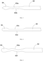
Fig. 1 is a structure schematic diagram of a filter provided by one embodiment of the present disclosure; -
Fig. 2 is a structure schematic diagram of a supporting rod of the filter of the present disclosure; -
Fig. 3 is a cross sectional view of a first embodiment of a flexible section of the supporting rod of the filter of the present disclosure; -
Fig. 4 is a cross sectional view of a second embodiment of a flexible section of the supporting rod of the filter of the present disclosure; -
Fig. 5 is a cross sectional view of a third embodiment of a flexible section of the supporting rod of the filter of the present disclosure; and -
Fig. 6 is a cross sectional view of a fourth embodiment of a flexible section of the supporting rod of the filter of the present disclosure. - To understand technical features, objectives and effects of the present disclosure more clearly, specific implementation modes of the present disclosure are described in detail now in combination with the accompanying drawings.
- As shown in
Fig. 1 and Fig. 2 , a filter 10 includes adistal end 1, aproximal end 2 and a filter main body connected between thedistal end 1 and theproximal end 2. The filter main body includes afirst filter unit 3, asecond filter unit 4 and multiplemiddle connecting rods 5 for connecting thefirst filter unit 3 with thesecond filter unit 4. The multiplemiddle connecting rods 5 are uniformly distributed around a connecting line between thedistal end 1 and theproximal end 2 in a spacing manner. Thefirst filter unit 3 is of a conical mesh structure and formed by gathering multiple Y-shapedfilter mesh rods 31 at thedistal end 1, and thesecond filter unit 4 is of a conical mesh structure and also formed by gathering multiple Y-shapedfilter mesh rods 41 at theproximal end 2. Furthermore, the number of the Y-shapedfilter mesh rods 31 of thefirst filter unit 3 is half than that of the Y-shapedfilter mesh rods 41 of thesecond filter unit 4, so that the filter 10 is of an overall asymmetric structure. This asymmetric structure is selective for thrombi to be filtered, that is, the filter only filters the thrombi causing pulmonary embolism, so as to guarantee long-term patency of a vena cava. Meanwhile, thedistal end 1 of the filter is also provided with a withdrawing hook (not marked) connected with a catcher when recycling a temporary filter. - Supporting rods 6 abutting with the blood vessel wall are also arranged on the
middle connecting rods 5 to enable themiddle connecting rods 5 to get far away from the blood vessel wall, so as to prevent a problem of short recovery window caused by the adhesion of the endangium to the surface of the filter. The supporting rods 6 includetransition sections 61 extending from themiddle connecting rods 5 towards a direction far away from the axis of the filter 10, and supporting sections extending from thetransition sections 61 towards the proximal end. At least part of the supporting sections are used for replacing the connectingrods 5 to abut with the blood vessel wall. Fixing anchors 7 for puncturing into the blood vessel wall are also arranged on some of the supporting rods 6. The fixing anchors 7 may enable the filter to be fixed more stably in the blood vessel. - Furthermore, in the present embodiment, only one supporting rod 6 is arranged on one
middle connecting rod 5, and the positions of the supporting rods 6 on adjacentmiddle connecting rods 5 are different, and the supporting rods are arranged in a staggered manner, so that the supporting rods may provide a more uniform and stabler supporting force for the filter, and it is able to prevent thrombus filtration effect of the filter from weakening due to inclination and displacement of the filter in the blood vessel, and the risk of postoperative pulmonary embolism may increase after surgery. In other possible embodiments, two or more supporting rods also may be arranged on each middle connecting rod. These supporting rods may be fixed at any position on the middle connecting rod as long as a direction of an opening defined by the transition sections and the supporting sections of the supporting rods are opposite to a direction in which the filter is removed. As shown inFig. 2 , each supporting section includes abody 62 bending and extending from the tail end of eachtransition section 61 and abutting with the blood vessel wall, aflexible section 63 extending from thebody 62 towards the proximal end, and a protrudingportion 64 arranged at the tail end of theflexible section 63 and having a smooth outer contour. The protrudingportion 64 and theflexible section 63 as well as thebody 62 and theflexible section 63 are in smooth transition. The smooth transition mentioned in the present disclosure means that a joint of two elements is in arc transition or chamfering transition. The rigidity of theflexible section 63 is less than that of thebody 62. There are various implementing methods to make the rigidity of theflexible section 63 less than that of thebody 62. In the present embodiment, the implementing method is to make the radial size of at least part of theflexible section 63 in a lengthwise direction less than that of thebody 62. Through reducing the radial size, the flexibility of this part of the supporting section may be improved, so that it is able to prevent the supporting section from puncturing through the blood vessel wall when the supporting section abuts with the blood vessel wall. In other implementation modes, theflexible section 63 also may be made of a flexible material, such as silica gel. - Further, an included angle between the
body 62 and themiddle connecting rod 5 is less than 90 degrees. It can be predicted that in case that the included angle between thebody 62 and themiddle connecting rod 5 is equal to 90 degrees, when the filter spreads in the blood vessel, thebody 62 would point to the blood vessel wall, which undoubtedly increases the risk that the supporting section punctures through the blood vessel wall. In case that the included angle between thebody 62 and themiddle connecting rod 5 is more than 90 degrees, for example, when thebody 62 and thetransition section 61 are located on the same straight line, thebody 62 still points to the blood vessel wall and is unable to support the blood vessel wall. In the present embodiment, theflexible section 63 and thebody 62 define an obtuse angle or are located on the same straight line, but theflexible section 63 and thebody 62 shall not define an acute angle, and reasons are as mentioned above. - The part, having the radial size less than that of the
body 62, of theflexible section 63 may be defined by means of stripping, and theflexible section 63 may have different shapes. Specific descriptions are made below through several specific embodiments. - As shown in
Fig. 3 , the cross section of eachflexible section 63 along the lengthwise direction of theflexible section 63 has anupper contour line 63a and alower contour line 63b opposite to theupper contour line 63a in a spacing manner, and theupper contour line 63a and thelower contour line 63b gradually get close to each other along an extending direction of theflexible section 63. That is to say, the radial size of theflexible section 63 is gradually reduced in its extending direction. Theflexible section 63 and thebody 62 are in arc transition. The tail end of theflexible section 63 is provided with a protrudingportion 64 of a quadrangular cross-section shape. The four side edges of the cross section of the protrudingportion 64 are all in smooth transition, and the protrudingportion 64 and theflexible section 63 are also in arc transition. The protrudingportion 64 may have a smooth outer contour by a mechanical method such as mechanical sand blasting and polishing, or by chemical method or by argon arc welding. The protrudingportion 64 added at the tail end of theflexible section 63 can further reduce the risk that the supporting section punctures through the blood vessel wall. - As shown in
Fig. 4 , the cross section of eachflexible section 63 along the lengthwise direction of theflexible section 63 has anupper contour line 63c and alower contour line 63d opposite to theupper contour line 63c in a spacing manner. In the present embodiment, thelower contour line 63d and the contour line of thebody 62 are located on the same straight line. Theupper contour line 63c gets close to thelower contour line 63d along the extending direction of theflexible section 63, and the radial size of the wholeflexible section 63 is equal. In addition, theupper contour line 63c of theflexible section 63 and the outer contour of thebody 62 are in chamfering transition. From the appearance, theflexible section 63 is a section of sunken groove formed in the tail section of the supporting section by means of stripping. It can be understood that theflexible section 63 also may be two sections of grooves formed in the upper and lower sides of the tail section of the supporting section by means of stripping, and has an equal radial size along its extending direction. In the present embodiment, the cross section of the protrudingportion 64 arranged at the tail end of theflexible section 63 is of an approximately track shape, and the protrudingportion 64 and theupper contour line 63c of theflexible section 63 are in chamfering transition. - As shown in
Fig. 5 , the cross section of theflexible section 63 along the lengthwise direction of theflexible section 63 has anupper contour line 63e and alower contour line 63f opposite to theupper contour line 63e in a spacing manner, and theupper contour line 63e and thelower contour line 63f are both wavy lines. The wave crests of theupper contour line 63e are opposite to the wave crests of thelower contour lines 63f, and the wave troughs of theupper contour line 63e are opposite to the wave troughs of thelower contour lines 63f. In the present embodiment, the cross section of the protrudingportion 64 arranged at the tail end of theflexible section 63 is of a water drop shape, and the protrudingportion 64 and theflexible section 63 are in arc transition. Theflexible section 63 and thebody 62 are in arc transition. - As shown in
Fig. 6 , as in the previous embodiments, the cross section of theflexible section 63 along the lengthwise direction of theflexible section 63 has anupper contour line 63e' and alower contour line 63f opposite to theupper contour line 63 e' in a spacing manner, and theupper contour line 63e' and thelower contour line 63f are both wavy lines. But in the present embodiment, the wave crests of theupper contour line 63e' are opposite to the wave troughs of thelower contour lines 63f, and the wave troughs of theupper contour line 63e' are opposite to the wave crests of thelower contour lines 63f. In the present embodiment, the cross section of the protrudingportion 64 arranged at the tail end of theflexible section 63 is circular, and the protrudingportion 64 and theflexible section 63 are in arc transition. Theflexible section 63 and thebody 62 are in arc transition. - In all the above-mentioned embodiments, the protruding
portion 64 may be of any shape. For example, the protruding portion may be elliptical as long as its outer contour is treated to be smooth to avoid the risk of puncturing through the blood vessel wall. Furthermore, when multiple supporting rods 6 are arranged on each middle connectingrod 5, the protrudingportions 64 may be selectively arranged at the tail ends of theflexible sections 63. - As the tails of the supporting rods of the filter of the present disclosure are provided with the flexible sections and the protruding portions having the smooth outer contours, and the parts, transitioned to the flexible sections, of the outer contours of the protruding portions are in smooth transition, this structural design reduces the risk that the supporting sections puncture through the blood vessel wall, and avoids postoperative complications caused by the fact that the supporting sections puncture through the blood vessel wall as much as possible, and solves the problem of mutual twisting of the open supporting rods during contracting or spreading of the filter, and improves the usability of the filter and guarantees a surgical success.
Claims (12)
- A filter, comprising a proximal end, a distal end and a filter main body connected between the proximal end and the distal end, the filter main body comprises a first filter unit and a second filter unit which are both of conical mesh structures, and a plurality of middle connecting rods for connecting the first filter unit with the second filter unit; a supporting rod is arranged on the middle supporting rod; wherein the supporting rod comprises a transition section extending from the middle connecting rod towards a direction far away from the axis of the filter, and a supporting section bending from the transition section towards a direction close to the axis of the filter and extending towards the proximal end; the supporting section comprises a body bending and extending from a tail end of the transition section, and a flexible section connected with the body; and the rigidity of the flexible section is less than that of the body.
- The filter according to claim 1, wherein the radial size of at least one part of the flexible section in a lengthwise direction of the flexible section is less than that of the body.
- The filter according to claim 2, wherein a cross section of the flexible section along the lengthwise direction of the flexible section has an upper contour line and a lower contour line opposite to the upper contour line in a spacing manner, and the upper contour line and the lower contour line get close to each other along an extending direction of the flexible section.
- The filter according to claim 2, wherein a cross section of the flexible section along the lengthwise direction of the flexible section has an upper contour line and a lower contour line opposite to the upper contour line in a spacing manner, and both the upper contour line and the lower contour line are wavy lines.
- The filter according to claim 4, wherein a wave crest of the upper contour line is opposite to a wave crest of the lower contour line, and a wave trough of the upper contour line is opposite to a wave trough of the lower contour line.
- The filter according to claim 4, wherein a wave crest of the upper contour line is opposite to a wave trough of the lower contour line.
- The filter according to claim 1, wherein the radial size of any point of the flexible section along a lengthwise direction of the flexible section is equal, and is less than that of the body.
- The filter according to claim 1, wherein the flexible section is made of a flexible material.
- The filter according to claim 1, wherein an included angle between the body and the middle connecting rod is less than 90 degrees.
- The filter according to claim 9, wherein an included angle between the flexible section and the body is obtuse angle, and the flexible section and the body are in smooth transition.
- The filter according to claim 1, wherein the supporting section further comprises a protruding portion that has a smooth outer contour and arranges at a tail end of the flexible section, and the protruding portion and the flexible section are in smooth transition.
- The filter according to claim 1, wherein supporting rods on two adjacent middle connecting rods are in staggered distribution.
Applications Claiming Priority (2)
| Application Number | Priority Date | Filing Date | Title |
|---|---|---|---|
| CN201611110963.2A CN108143518B (en) | 2016-12-06 | 2016-12-06 | filter |
| PCT/CN2017/099026 WO2018103375A1 (en) | 2016-12-06 | 2017-08-25 | Filter |
Publications (3)
| Publication Number | Publication Date |
|---|---|
| EP3552576A1 EP3552576A1 (en) | 2019-10-16 |
| EP3552576A4 EP3552576A4 (en) | 2020-10-14 |
| EP3552576B1 true EP3552576B1 (en) | 2024-12-04 |
Family
ID=62468344
Family Applications (1)
| Application Number | Title | Priority Date | Filing Date |
|---|---|---|---|
| EP17877963.3A Active EP3552576B1 (en) | 2016-12-06 | 2017-08-25 | Filter |
Country Status (5)
| Country | Link |
|---|---|
| US (1) | US11166805B2 (en) |
| EP (1) | EP3552576B1 (en) |
| CN (1) | CN108143518B (en) |
| ES (1) | ES3009678T3 (en) |
| WO (1) | WO2018103375A1 (en) |
Families Citing this family (2)
| Publication number | Priority date | Publication date | Assignee | Title |
|---|---|---|---|---|
| CN108143518B (en) | 2016-12-06 | 2020-10-27 | 先健科技(深圳)有限公司 | filter |
| CN111789697B (en) * | 2020-07-10 | 2023-10-24 | 埃文斯科技(北京)有限公司 | Vena cava filter with anti-tilting support arm and processing method thereof |
Citations (1)
| Publication number | Priority date | Publication date | Assignee | Title |
|---|---|---|---|---|
| WO2018082378A1 (en) * | 2016-11-02 | 2018-05-11 | 先健科技(深圳)有限公司 | Filter |
Family Cites Families (19)
| Publication number | Priority date | Publication date | Assignee | Title |
|---|---|---|---|---|
| US7314477B1 (en) * | 1998-09-25 | 2008-01-01 | C.R. Bard Inc. | Removable embolus blood clot filter and filter delivery unit |
| US7147649B2 (en) * | 2000-08-04 | 2006-12-12 | Duke University | Temporary vascular filters |
| US9204956B2 (en) * | 2002-02-20 | 2015-12-08 | C. R. Bard, Inc. | IVC filter with translating hooks |
| US20040087999A1 (en) * | 2002-10-31 | 2004-05-06 | Gjalt Bosma | Vascular filter with improved anchor or other position retention |
| AU2003285248A1 (en) * | 2002-11-29 | 2004-06-23 | Vascular Interventional Technologies Inc. | Embolus blood clot filter |
| US8801746B1 (en) * | 2004-05-04 | 2014-08-12 | Covidien Lp | System and method for delivering a left atrial appendage containment device |
| CN100413471C (en) * | 2004-06-25 | 2008-08-27 | 深圳市先健科技股份有限公司 | Latching of left auricular appendix and conveyor thereof |
| US9107733B2 (en) * | 2006-01-13 | 2015-08-18 | W. L. Gore & Associates, Inc. | Removable blood conduit filter |
| WO2008077067A2 (en) * | 2006-12-19 | 2008-06-26 | C.R. Bard Inc. | Inferior vena cava filter with stability features |
| US20080275487A1 (en) * | 2007-05-01 | 2008-11-06 | Fleming James A | Removable medical filter with stand-off arms |
| US8246648B2 (en) * | 2008-11-10 | 2012-08-21 | Cook Medical Technologies Llc | Removable vena cava filter with improved leg |
| US8940012B2 (en) * | 2010-12-07 | 2015-01-27 | Boston Scientific Scimed, Inc. | Intravascular filter with biodegradable force-reducing element |
| CN102330059B (en) | 2011-09-19 | 2013-06-12 | 成都西南交大科技园管理有限责任公司 | Preparation method of recyclable surface film of inferior vena cava filter based on (PEG) polyethylene glycol-like |
| CN105796207B (en) * | 2014-12-30 | 2018-05-11 | 先健科技(深圳)有限公司 | Filter and preparation method thereof |
| CN204909721U (en) * | 2015-06-30 | 2015-12-30 | 先健科技(深圳)有限公司 | Filter |
| CN106308974B (en) | 2015-06-30 | 2018-08-03 | 先健科技(深圳)有限公司 | Filter |
| CN105662646A (en) * | 2015-12-29 | 2016-06-15 | 先健科技(深圳)有限公司 | Filter |
| CN108143518B (en) | 2016-12-06 | 2020-10-27 | 先健科技(深圳)有限公司 | filter |
| CN206630733U (en) * | 2016-12-06 | 2017-11-14 | 先健科技(深圳)有限公司 | Filter |
-
2016
- 2016-12-06 CN CN201611110963.2A patent/CN108143518B/en active Active
-
2017
- 2017-08-25 WO PCT/CN2017/099026 patent/WO2018103375A1/en not_active Ceased
- 2017-08-25 ES ES17877963T patent/ES3009678T3/en active Active
- 2017-08-25 EP EP17877963.3A patent/EP3552576B1/en active Active
- 2017-08-25 US US16/464,614 patent/US11166805B2/en active Active
Patent Citations (1)
| Publication number | Priority date | Publication date | Assignee | Title |
|---|---|---|---|---|
| WO2018082378A1 (en) * | 2016-11-02 | 2018-05-11 | 先健科技(深圳)有限公司 | Filter |
Also Published As
| Publication number | Publication date |
|---|---|
| CN108143518A (en) | 2018-06-12 |
| EP3552576A4 (en) | 2020-10-14 |
| ES3009678T3 (en) | 2025-03-31 |
| CN108143518B (en) | 2020-10-27 |
| EP3552576A1 (en) | 2019-10-16 |
| WO2018103375A1 (en) | 2018-06-14 |
| US11166805B2 (en) | 2021-11-09 |
| US20210093434A1 (en) | 2021-04-01 |
Similar Documents
| Publication | Publication Date | Title |
|---|---|---|
| CN113855167B (en) | Clot removal device for ischemic stroke treatment | |
| US7909847B2 (en) | Vein filter | |
| US10194928B2 (en) | Systems and methods for restoring blood flow to a vessel | |
| CN109984860B (en) | Intravascular filter | |
| EP3552576B1 (en) | Filter | |
| WO2008034315A1 (en) | Double deck venous fileter | |
| CN206630733U (en) | Filter | |
| CN105662646A (en) | Filter | |
| CN105102052A (en) | Blood flow restriction method and apparatus for resection of thrombus in human vasculature | |
| CN107137160A (en) | Prevent the two-way controlled release filter of displacement | |
| CN106913392A (en) | Filter | |
| CN110169843A (en) | A kind of lotus flap-type bilayer point support recoverable version vena cava filter and production method | |
| CN205494080U (en) | Filter | |
| US20080300620A1 (en) | Embolic filter made from a composite material | |
| CN108143517B (en) | Filter device | |
| CN205494083U (en) | Filter | |
| CN215129841U (en) | Protection system with stem leaf imitating structure | |
| CN205494082U (en) | Filter | |
| CN215307027U (en) | Vena cava filter | |
| CN206761795U (en) | Filter | |
| RU2127565C1 (en) | Superelastic nitinol antiembolic intravenous filter "sandglass" | |
| CN108013951A (en) | Filter | |
| CN205612590U (en) | Novel multiple filter of recoverable vena cave thrombus | |
| CN118766546A (en) | A vascular thrombectomy frame | |
| EP3733119A1 (en) | Filter |
Legal Events
| Date | Code | Title | Description |
|---|---|---|---|
| STAA | Information on the status of an ep patent application or granted ep patent |
Free format text: STATUS: THE INTERNATIONAL PUBLICATION HAS BEEN MADE |
|
| PUAI | Public reference made under article 153(3) epc to a published international application that has entered the european phase |
Free format text: ORIGINAL CODE: 0009012 |
|
| STAA | Information on the status of an ep patent application or granted ep patent |
Free format text: STATUS: REQUEST FOR EXAMINATION WAS MADE |
|
| 17P | Request for examination filed |
Effective date: 20190627 |
|
| AK | Designated contracting states |
Kind code of ref document: A1 Designated state(s): AL AT BE BG CH CY CZ DE DK EE ES FI FR GB GR HR HU IE IS IT LI LT LU LV MC MK MT NL NO PL PT RO RS SE SI SK SM TR |
|
| AX | Request for extension of the european patent |
Extension state: BA ME |
|
| DAV | Request for validation of the european patent (deleted) | ||
| DAX | Request for extension of the european patent (deleted) | ||
| A4 | Supplementary search report drawn up and despatched |
Effective date: 20200914 |
|
| RIC1 | Information provided on ipc code assigned before grant |
Ipc: A61F 2/01 20060101AFI20200908BHEP |
|
| GRAP | Despatch of communication of intention to grant a patent |
Free format text: ORIGINAL CODE: EPIDOSNIGR1 |
|
| STAA | Information on the status of an ep patent application or granted ep patent |
Free format text: STATUS: GRANT OF PATENT IS INTENDED |
|
| INTG | Intention to grant announced |
Effective date: 20240712 |
|
| GRAS | Grant fee paid |
Free format text: ORIGINAL CODE: EPIDOSNIGR3 |
|
| GRAA | (expected) grant |
Free format text: ORIGINAL CODE: 0009210 |
|
| STAA | Information on the status of an ep patent application or granted ep patent |
Free format text: STATUS: THE PATENT HAS BEEN GRANTED |
|
| P01 | Opt-out of the competence of the unified patent court (upc) registered |
Free format text: CASE NUMBER: APP_56300/2024 Effective date: 20241015 |
|
| AK | Designated contracting states |
Kind code of ref document: B1 Designated state(s): AL AT BE BG CH CY CZ DE DK EE ES FI FR GB GR HR HU IE IS IT LI LT LU LV MC MK MT NL NO PL PT RO RS SE SI SK SM TR |
|
| REG | Reference to a national code |
Ref country code: GB Ref legal event code: FG4D |
|
| REG | Reference to a national code |
Ref country code: CH Ref legal event code: EP |
|
| REG | Reference to a national code |
Ref country code: DE Ref legal event code: R096 Ref document number: 602017086620 Country of ref document: DE |
|
| REG | Reference to a national code |
Ref country code: IE Ref legal event code: FG4D |
|
| REG | Reference to a national code |
Ref country code: LT Ref legal event code: MG9D |
|
| REG | Reference to a national code |
Ref country code: ES Ref legal event code: FG2A Ref document number: 3009678 Country of ref document: ES Kind code of ref document: T3 Effective date: 20250331 |
|
| REG | Reference to a national code |
Ref country code: NL Ref legal event code: MP Effective date: 20241204 |
|
| PG25 | Lapsed in a contracting state [announced via postgrant information from national office to epo] |
Ref country code: HR Free format text: LAPSE BECAUSE OF FAILURE TO SUBMIT A TRANSLATION OF THE DESCRIPTION OR TO PAY THE FEE WITHIN THE PRESCRIBED TIME-LIMIT Effective date: 20241204 |
|
| PG25 | Lapsed in a contracting state [announced via postgrant information from national office to epo] |
Ref country code: FI Free format text: LAPSE BECAUSE OF FAILURE TO SUBMIT A TRANSLATION OF THE DESCRIPTION OR TO PAY THE FEE WITHIN THE PRESCRIBED TIME-LIMIT Effective date: 20241204 |
|
| PG25 | Lapsed in a contracting state [announced via postgrant information from national office to epo] |
Ref country code: BG Free format text: LAPSE BECAUSE OF FAILURE TO SUBMIT A TRANSLATION OF THE DESCRIPTION OR TO PAY THE FEE WITHIN THE PRESCRIBED TIME-LIMIT Effective date: 20241204 |
|
| PG25 | Lapsed in a contracting state [announced via postgrant information from national office to epo] |
Ref country code: NO Free format text: LAPSE BECAUSE OF FAILURE TO SUBMIT A TRANSLATION OF THE DESCRIPTION OR TO PAY THE FEE WITHIN THE PRESCRIBED TIME-LIMIT Effective date: 20250304 |
|
| PG25 | Lapsed in a contracting state [announced via postgrant information from national office to epo] |
Ref country code: LV Free format text: LAPSE BECAUSE OF FAILURE TO SUBMIT A TRANSLATION OF THE DESCRIPTION OR TO PAY THE FEE WITHIN THE PRESCRIBED TIME-LIMIT Effective date: 20241204 Ref country code: GR Free format text: LAPSE BECAUSE OF FAILURE TO SUBMIT A TRANSLATION OF THE DESCRIPTION OR TO PAY THE FEE WITHIN THE PRESCRIBED TIME-LIMIT Effective date: 20250305 |
|
| PG25 | Lapsed in a contracting state [announced via postgrant information from national office to epo] |
Ref country code: RS Free format text: LAPSE BECAUSE OF FAILURE TO SUBMIT A TRANSLATION OF THE DESCRIPTION OR TO PAY THE FEE WITHIN THE PRESCRIBED TIME-LIMIT Effective date: 20250304 |
|
| PG25 | Lapsed in a contracting state [announced via postgrant information from national office to epo] |
Ref country code: NL Free format text: LAPSE BECAUSE OF FAILURE TO SUBMIT A TRANSLATION OF THE DESCRIPTION OR TO PAY THE FEE WITHIN THE PRESCRIBED TIME-LIMIT Effective date: 20241204 |
|
| REG | Reference to a national code |
Ref country code: AT Ref legal event code: MK05 Ref document number: 1747318 Country of ref document: AT Kind code of ref document: T Effective date: 20241204 |
|
| PG25 | Lapsed in a contracting state [announced via postgrant information from national office to epo] |
Ref country code: SM Free format text: LAPSE BECAUSE OF FAILURE TO SUBMIT A TRANSLATION OF THE DESCRIPTION OR TO PAY THE FEE WITHIN THE PRESCRIBED TIME-LIMIT Effective date: 20241204 |
|
| PG25 | Lapsed in a contracting state [announced via postgrant information from national office to epo] |
Ref country code: PL Free format text: LAPSE BECAUSE OF FAILURE TO SUBMIT A TRANSLATION OF THE DESCRIPTION OR TO PAY THE FEE WITHIN THE PRESCRIBED TIME-LIMIT Effective date: 20241204 |
|
| PG25 | Lapsed in a contracting state [announced via postgrant information from national office to epo] |
Ref country code: IS Free format text: LAPSE BECAUSE OF FAILURE TO SUBMIT A TRANSLATION OF THE DESCRIPTION OR TO PAY THE FEE WITHIN THE PRESCRIBED TIME-LIMIT Effective date: 20250404 |
|
| PG25 | Lapsed in a contracting state [announced via postgrant information from national office to epo] |
Ref country code: PT Free format text: LAPSE BECAUSE OF FAILURE TO SUBMIT A TRANSLATION OF THE DESCRIPTION OR TO PAY THE FEE WITHIN THE PRESCRIBED TIME-LIMIT Effective date: 20250404 |
|
| PG25 | Lapsed in a contracting state [announced via postgrant information from national office to epo] |
Ref country code: EE Free format text: LAPSE BECAUSE OF FAILURE TO SUBMIT A TRANSLATION OF THE DESCRIPTION OR TO PAY THE FEE WITHIN THE PRESCRIBED TIME-LIMIT Effective date: 20241204 |
|
| PG25 | Lapsed in a contracting state [announced via postgrant information from national office to epo] |
Ref country code: RO Free format text: LAPSE BECAUSE OF FAILURE TO SUBMIT A TRANSLATION OF THE DESCRIPTION OR TO PAY THE FEE WITHIN THE PRESCRIBED TIME-LIMIT Effective date: 20241204 Ref country code: AT Free format text: LAPSE BECAUSE OF FAILURE TO SUBMIT A TRANSLATION OF THE DESCRIPTION OR TO PAY THE FEE WITHIN THE PRESCRIBED TIME-LIMIT Effective date: 20241204 |
|
| PG25 | Lapsed in a contracting state [announced via postgrant information from national office to epo] |
Ref country code: SK Free format text: LAPSE BECAUSE OF FAILURE TO SUBMIT A TRANSLATION OF THE DESCRIPTION OR TO PAY THE FEE WITHIN THE PRESCRIBED TIME-LIMIT Effective date: 20241204 |
|
| PG25 | Lapsed in a contracting state [announced via postgrant information from national office to epo] |
Ref country code: CZ Free format text: LAPSE BECAUSE OF FAILURE TO SUBMIT A TRANSLATION OF THE DESCRIPTION OR TO PAY THE FEE WITHIN THE PRESCRIBED TIME-LIMIT Effective date: 20241204 |
|
| REG | Reference to a national code |
Ref country code: DE Ref legal event code: R097 Ref document number: 602017086620 Country of ref document: DE |
|
| PG25 | Lapsed in a contracting state [announced via postgrant information from national office to epo] |
Ref country code: SE Free format text: LAPSE BECAUSE OF FAILURE TO SUBMIT A TRANSLATION OF THE DESCRIPTION OR TO PAY THE FEE WITHIN THE PRESCRIBED TIME-LIMIT Effective date: 20241204 |
|
| PGFP | Annual fee paid to national office [announced via postgrant information from national office to epo] |
Ref country code: ES Payment date: 20250908 Year of fee payment: 9 |
|
| PG25 | Lapsed in a contracting state [announced via postgrant information from national office to epo] |
Ref country code: DK Free format text: LAPSE BECAUSE OF FAILURE TO SUBMIT A TRANSLATION OF THE DESCRIPTION OR TO PAY THE FEE WITHIN THE PRESCRIBED TIME-LIMIT Effective date: 20241204 |
|
| PGFP | Annual fee paid to national office [announced via postgrant information from national office to epo] |
Ref country code: DE Payment date: 20250812 Year of fee payment: 9 |
|
| PLBE | No opposition filed within time limit |
Free format text: ORIGINAL CODE: 0009261 |
|
| STAA | Information on the status of an ep patent application or granted ep patent |
Free format text: STATUS: NO OPPOSITION FILED WITHIN TIME LIMIT |
|
| PGFP | Annual fee paid to national office [announced via postgrant information from national office to epo] |
Ref country code: IT Payment date: 20250808 Year of fee payment: 9 |
|
| REG | Reference to a national code |
Ref country code: CH Ref legal event code: L10 Free format text: ST27 STATUS EVENT CODE: U-0-0-L10-L00 (AS PROVIDED BY THE NATIONAL OFFICE) Effective date: 20251015 |
|
| 26N | No opposition filed |
Effective date: 20250905 |
|
| REG | Reference to a national code |
Ref country code: CH Ref legal event code: H13 Free format text: ST27 STATUS EVENT CODE: U-0-0-H10-H13 (AS PROVIDED BY THE NATIONAL OFFICE) Effective date: 20260324 |
|
| PG25 | Lapsed in a contracting state [announced via postgrant information from national office to epo] |
Ref country code: MC Free format text: LAPSE BECAUSE OF FAILURE TO SUBMIT A TRANSLATION OF THE DESCRIPTION OR TO PAY THE FEE WITHIN THE PRESCRIBED TIME-LIMIT Effective date: 20241204 |
|
| PG25 | Lapsed in a contracting state [announced via postgrant information from national office to epo] |
Ref country code: LU Free format text: LAPSE BECAUSE OF NON-PAYMENT OF DUE FEES Effective date: 20250825 |