EP3552442B1 - Ota-phasensynchronisation für reziprozitätsbasierte gemeinsame comp-übertragung - Google Patents
Ota-phasensynchronisation für reziprozitätsbasierte gemeinsame comp-übertragung Download PDFInfo
- Publication number
- EP3552442B1 EP3552442B1 EP17818390.1A EP17818390A EP3552442B1 EP 3552442 B1 EP3552442 B1 EP 3552442B1 EP 17818390 A EP17818390 A EP 17818390A EP 3552442 B1 EP3552442 B1 EP 3552442B1
- Authority
- EP
- European Patent Office
- Prior art keywords
- psrs
- base stations
- phase drift
- base station
- channel estimate
- Prior art date
- Legal status (The legal status is an assumption and is not a legal conclusion. Google has not performed a legal analysis and makes no representation as to the accuracy of the status listed.)
- Active
Links
Images


Classifications
-
- H—ELECTRICITY
- H04—ELECTRIC COMMUNICATION TECHNIQUE
- H04W—WIRELESS COMMUNICATION NETWORKS
- H04W56/00—Synchronisation arrangements
- H04W56/0035—Synchronisation arrangements detecting errors in frequency or phase
-
- H—ELECTRICITY
- H04—ELECTRIC COMMUNICATION TECHNIQUE
- H04B—TRANSMISSION
- H04B1/00—Details of transmission systems, not covered by a single one of groups H04B3/00 - H04B13/00; Details of transmission systems not characterised by the medium used for transmission
- H04B1/38—Transceivers, i.e. devices in which transmitter and receiver form a structural unit and in which at least one part is used for functions of transmitting and receiving
- H04B1/40—Circuits
- H04B1/403—Circuits using the same oscillator for generating both the transmitter frequency and the receiver local oscillator frequency
-
- H—ELECTRICITY
- H04—ELECTRIC COMMUNICATION TECHNIQUE
- H04B—TRANSMISSION
- H04B7/00—Radio transmission systems, i.e. using radiation field
- H04B7/02—Diversity systems; Multi-antenna system, i.e. transmission or reception using multiple antennas
- H04B7/022—Site diversity; Macro-diversity
- H04B7/024—Co-operative use of antennas of several sites, e.g. in co-ordinated multipoint or co-operative multiple-input multiple-output [MIMO] systems
-
- H—ELECTRICITY
- H04—ELECTRIC COMMUNICATION TECHNIQUE
- H04L—TRANSMISSION OF DIGITAL INFORMATION, e.g. TELEGRAPHIC COMMUNICATION
- H04L25/00—Baseband systems
- H04L25/02—Details ; arrangements for supplying electrical power along data transmission lines
- H04L25/0202—Channel estimation
- H04L25/0204—Channel estimation of multiple channels
-
- H—ELECTRICITY
- H04—ELECTRIC COMMUNICATION TECHNIQUE
- H04L—TRANSMISSION OF DIGITAL INFORMATION, e.g. TELEGRAPHIC COMMUNICATION
- H04L25/00—Baseband systems
- H04L25/02—Details ; arrangements for supplying electrical power along data transmission lines
- H04L25/0202—Channel estimation
- H04L25/0224—Channel estimation using sounding signals
-
- H—ELECTRICITY
- H04—ELECTRIC COMMUNICATION TECHNIQUE
- H04L—TRANSMISSION OF DIGITAL INFORMATION, e.g. TELEGRAPHIC COMMUNICATION
- H04L25/00—Baseband systems
- H04L25/02—Details ; arrangements for supplying electrical power along data transmission lines
- H04L25/03—Shaping networks in transmitter or receiver, e.g. adaptive shaping networks
- H04L25/0398—Restoration of channel reciprocity
-
- H—ELECTRICITY
- H04—ELECTRIC COMMUNICATION TECHNIQUE
- H04W—WIRELESS COMMUNICATION NETWORKS
- H04W56/00—Synchronisation arrangements
- H04W56/001—Synchronization between nodes
- H04W56/0015—Synchronization between nodes one node acting as a reference for the others
-
- H—ELECTRICITY
- H04—ELECTRIC COMMUNICATION TECHNIQUE
- H04L—TRANSMISSION OF DIGITAL INFORMATION, e.g. TELEGRAPHIC COMMUNICATION
- H04L25/00—Baseband systems
- H04L25/02—Details ; arrangements for supplying electrical power along data transmission lines
- H04L25/0202—Channel estimation
-
- H—ELECTRICITY
- H04—ELECTRIC COMMUNICATION TECHNIQUE
- H04L—TRANSMISSION OF DIGITAL INFORMATION, e.g. TELEGRAPHIC COMMUNICATION
- H04L5/00—Arrangements affording multiple use of the transmission path
- H04L5/003—Arrangements for allocating sub-channels of the transmission path
- H04L5/0032—Distributed allocation, i.e. involving a plurality of allocating devices, each making partial allocation
- H04L5/0035—Resource allocation in a cooperative multipoint environment
Definitions
- aspects of the present disclosure relate generally to wireless communication systems, and more particularly, to over-the-air (OTA) phase synchronization for reciprocity-based coordinated multipoint (CoMP) joint transmission.
- OTA over-the-air
- CoMP coordinated multipoint
- Wireless communication networks are widely deployed to provide various communication services such as voice, video, packet data, messaging, broadcast, and the like. These wireless networks may be multiple-access networks capable of supporting multiple users by sharing the available network resources. Such networks, which are usually multiple access networks, support communications for multiple users by sharing the available network resources.
- UTRAN Universal Terrestrial Radio Access Network
- the UTRAN is the radio access network (RAN) defined as a part of the Universal Mobile Telecommunications System (UMTS), a third generation (3G) mobile phone technology supported by the 3rd Generation Partnership Project (3GPP).
- UMTS Universal Mobile Telecommunications System
- 3GPP 3rd Generation Partnership Project
- multiple-access network formats include Code Division Multiple Access (CDMA) networks, Time Division Multiple Access (TDMA) networks, Frequency Division Multiple Access (FDMA) networks, Orthogonal FDMA (OFDMA) networks, and Single-Carrier FDMA (SC-FDMA) networks.
- CDMA Code Division Multiple Access
- TDMA Time Division Multiple Access
- FDMA Frequency Division Multiple Access
- OFDMA Orthogonal FDMA
- SC-FDMA Single-Carrier FDMA
- a wireless communication network may include a number of base stations or node Bs that can support communication for a number of user equipments (UEs).
- a UE may communicate with a base station via downlink and uplink.
- the downlink (or forward link) refers to the communication link from the base station to the UE
- the uplink (or reverse link) refers to the communication link from the UE to the base station.
- a base station may transmit data and control information on the downlink to a UE and/or may receive data and control information on the uplink from the UE.
- a transmission from the base station may encounter interference due to transmissions from neighbor base stations or from other wireless radio frequency (RF) transmitters.
- RF radio frequency
- a transmission from the UE may encounter interference from uplink transmissions of other UEs communicating with the neighbor base stations or from other wireless RF transmitters. This interference may degrade performance on both the downlink and uplink.
- a method of wireless communication includes transmitting, by a base station, a first phase synchronization reference signal (PSRS), wherein the base station is one of a plurality of cooperating base stations in a coordinating set of base stations, receiving, at the base station, a second PSRS, measuring, at the base station, a receive chain phase drift based on the received second PSRS, obtaining, at the base station, a transmit chain phase drift based on the first PSRS, determining, by the base station, a relative phase drift between a downlink channel and an uplink channel using the receive chain phase drift and the transmit chain phase drift, determining, by the base station, a relative coordinating phase drift among all cooperating base stations in the coordinating set of base stations, generating, by the base station, an uplink channel estimate based on a sounding reference signal (SRS) received from a user equipment (UE), and generating, by the base station, a downlink channel estimate based on the uplink channel estimate,
- SRS sounding reference signal
- an apparatus configured for wireless communication including means for transmitting a first PSRS, wherein the apparatus is one of a plurality of cooperating base stations in a coordinating set of base stations, means for receiving a second PSRS, means for measuring a receive chain phase drift based on the received second PSRS, means for obtaining a transmit chain phase drift based on the first PSRS, means for determining a relative phase drift between a downlink channel and an uplink channel using the receive chain phase drift and the transmit chain phase drift, means for determining a relative coordinating phase drift among all cooperating base stations in the coordinating set of base stations, means for generating an uplink channel estimate based on a SRS received from a UE, and means for generating a downlink channel estimate based on the uplink channel estimate, the relative phase drift, and the relative coordinating phase drift.
- a non-transitory computer-readable medium having program code recorded thereon.
- the program code further includes code to transmit, by a base station, a first PSRS, wherein the base station is one of a plurality of cooperating base stations in a coordinating set of base stations, code to receive, at the base station, a second PSRS, code to measure, at the base station, a receive chain phase drift based on the received second PSRS, code to obtain, at the base station, a transmit chain phase drift based on the first PSRS, code to determine, by the base station, a relative phase drift between a downlink channel and an uplink channel using the receive chain phase drift and the transmit chain phase drift, code to determine, by the base station, a relative coordinating phase drift among all cooperating base stations in the coordinating set of base stations, code to generate, by the base station, an uplink channel estimate based on a SRS received from a UE, and code to generate, by the base station, a downlink channel estimate based on the uplink
- This disclosure relates generally to providing or participating in authorized shared access between two or more wireless communications systems, also referred to as wireless communications networks.
- the techniques and apparatus may be used for wireless communication networks such as code division multiple access (CDMA) networks, time division multiple access (TDMA) networks, frequency division multiple access (FDMA) networks, orthogonal FDMA (OFDMA) networks, single-carrier FDMA (SC-FDMA) networks, LTE networks, GSM networks, as well as other communications networks.
- CDMA code division multiple access
- TDMA time division multiple access
- FDMA frequency division multiple access
- OFDMA orthogonal FDMA
- SC-FDMA single-carrier FDMA
- An OFDMA network may implement a radio technology such as evolved UTRA (E-UTRA), IEEE 802.11, IEEE 802.16, IEEE 802.20, flash-OFDM and the like.
- E-UTRA evolved UTRA
- GSM Global System for Mobile Communications
- LTE long term evolution
- UTRA, E-UTRA, GSM, UMTS and LTE are described in documents provided from an organization named "3rd Generation Partnership Project” (3GPP), and cdma2000 is described in documents from an organization named "3rd Generation Partnership Project 2" (3GPP2).
- 3GPP 3rd Generation Partnership Project
- 3GPP long term evolution LTE
- UMTS universal mobile telecommunications system
- the 3GPP may define specifications for the next generation of mobile networks, mobile systems, and mobile devices.
- the present disclosure is concerned with the evolution of wireless technologies from LTE, 4G, 5G, and beyond with shared access to wireless spectrum between networks using a collection of new and different radio access technologies or radio air interfaces.
- 5G networks contemplate diverse deployments, diverse spectrum, and diverse services and devices that may be implemented using an OFDM-based unified, air interface.
- LTE and LTE-A are considered in addition to development of a new radio (NR) technology.
- the 5G NR will be capable of scaling to provide coverage (1) to a massive Internet of things (IoTs) with an ultra-high density (e.g., ⁇ 1M nodes/km 2 ), ultra-low complexity (e.g., ⁇ 10s of bits/sec), ultra-low energy (e.g., ⁇ 10+ years of battery life), and deep coverage with the capability to reach challenging locations; (2) including mission-critical control with strong security to safeguard sensitive personal, financial, or classified information, ultra-high reliability (e.g., ⁇ 99.9999% reliability), ultra-low latency (e.g., ⁇ 1 ms), and users with wide ranges of mobility or lack thereof; and (3) with enhanced mobile broadband including extreme high capacity (e.g., ⁇ 10 Tbps/km 2 ), extreme data rates (e.g., multi-Gbps rate, 100+ Mbps user experienced rates), and deep awareness with advanced discovery and optimizations.
- IoTs Internet of things
- ultra-high density e.g., ⁇ 1M nodes/km
- the 5G NR may be implemented to use optimized OFDM-based waveforms with scalable numerology and transmission time interval (TTI); having a common, flexible framework to efficiently multiplex services and features with a dynamic, low-latency time division duplex (TDD)/frequency division duplex (FDD) design; and with advanced wireless technologies, such as massive multiple input, multiple output (MIMO), robust millimeter wave (mmWave) transmissions, advanced channel coding, and device-centric mobility.
- TTI numerology and transmission time interval
- subcarrier spacing may occur with 15 kHz, for example over 1, 5, 10, 20 MHz, and the like bandwidth.
- subcarrier spacing may occur with 30 kHz over 80/100 MHz bandwidth.
- the subcarrier spacing may occur with 60 kHz over a 160 MHz bandwidth.
- subcarrier spacing may occur with 120 kHz over a 500MHz bandwidth.
- the scalable numerology of the 5G NR facilitates scalable TTI for diverse latency and quality of service (QoS) requirements. For example, shorter TTI may be used for low latency and high reliability, while longer TTI may be used for higher spectral efficiency.
- QoS quality of service
- 5G NR also contemplates a self-contained integrated subframe design with uplink/downlink scheduling information, data, and acknowledgement in the same subframe.
- the self-contained integrated subframe supports communications in unlicensed or contention-based shared spectrum, adaptive uplink/downlink that may be flexibly configured on a per-cell basis to dynamically switch between uplink and downlink to meet the current traffic needs.
- an aspect disclosed herein may be implemented independently of any other aspects and that two or more of these aspects may be combined in various ways.
- an apparatus may be implemented or a method may be practiced using any number of the aspects set forth herein.
- such an apparatus may be implemented or such a method may be practiced using other structure, functionality, or structure and functionality in addition to or other than one or more of the aspects set forth herein.
- a method may be implemented as part of a system, device, apparatus, and/or as instructions stored on a computer readable medium for execution on a processor or computer.
- an aspect may comprise at least one element of a claim.
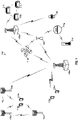
- FIG. 1 is a block diagram illustrating 5G network 100 including various base stations and UEs configured according to aspects of the present disclosure.
- the 5G network 100 includes a number of evolved node Bs (eNBs) 105 and other network entities.
- An eNB may be a station that communicates with the UEs and may also be referred to as a base station, a an access point, and the like.
- Each eNB 105 may provide communication coverage for a particular geographic area.
- the term "cell" can refer to this particular geographic coverage area of an eNB and/or an eNB subsystem serving the coverage area, depending on the context in which the term is used.
- An eNB may provide communication coverage for a macro cell or a small cell, such as a pico cell or a femto cell, and/or other types of cell.
- a macro cell generally covers a relatively large geographic area (e.g., several kilometers in radius) and may allow unrestricted access by UEs with service subscriptions with the network provider.
- a small cell, such as a pico cell would generally cover a relatively smaller geographic area and may allow unrestricted access by UEs with service subscriptions with the network provider.
- a small cell such as a femto cell, would also generally cover a relatively small geographic area (e.g., a home) and, in addition to unrestricted access, may also provide restricted access by UEs having an association with the femto cell (e.g., UEs in a closed subscriber group (CSG), UEs for users in the home, and the like).
- An eNB for a macro cell may be referred to as a macro eNB.
- An eNB for a small cell may be referred to as a small cell eNB, a pico eNB, a femto eNB or a home eNB.
- the eNBs 105d and 105e are regular macro eNBs, while eNBs 105a-105c are macro eNBs enabled with one of 3 dimension (3D), full dimension (FD), or massive MIMO.
- eNBs 105a-105c take advantage of their higher dimension MIMO capabilities to exploit 3D beamforming in both elevation and azimuth beamforming to increase coverage and capacity.
- eNB 105f is a small cell eNB which may be a home node or portable access point.
- An eNB may support one or multiple (e.g., two, three, four, and the like) cells.
- the 5G network 100 may support synchronous or asynchronous operation.
- the eNBs may have similar frame timing, and transmissions from different eNBs may be approximately aligned in time.
- the eNBs may have different frame timing, and transmissions from different eNBs may not be aligned in time.
- the UEs 115 are dispersed throughout the wireless network 100, and each UE may be stationary or mobile.
- a UE may also be referred to as a terminal, a mobile station, a subscriber unit, a station, or the like.
- a UE may be a cellular phone, a personal digital assistant (PDA), a wireless modem, a wireless communication device, a handheld device, a tablet computer, a laptop computer, a cordless phone, a wireless local loop (WLL) station, or the like.
- PDA personal digital assistant
- WLL wireless local loop
- UEs 115a-115d are examples of mobile smart phone-type devices accessing 5G network 100
- a UE may also be a machine specifically configured for connected communication, including machine type communication (MTC), enhanced MTC (eMTC), narrowband IoT (NB-IoT) and the like.
- UEs 115e-115k are examples of various machines configured for communication that access 5G network 100.
- a UE may be able to communicate with any type of the eNBs, whether macro eNB, small cell, or the like.
- MTC machine type communication
- eMTC enhanced MTC
- NB-IoT narrowband IoT
- UEs 115e-115k are examples of various machines configured for communication that access 5G network 100.
- a UE may be able to communicate with any type of the eNBs, whether macro eNB, small cell, or the like.
- a lightning bolt (e.g., communication links) indicates wireless transmissions between a UE and a serving eNB, which is an eNB designated to serve the UE on the downlink and/or uplink, or desired transmission between eNBs, and backhaul transmissions between eNBs.
- eNBs 105a-105c serve UEs 115a and 115b using 3D beamforming and coordinated spatial techniques, such as coordinated multipoint (CoMP) or multi-connectivity.
- Macro eNB 105d performs backhaul communications with eNBs 105a-105c, as well as small cell, eNB 105f.
- Macro eNB 105d also transmits multicast services which are subscribed to and received by UEs 115c and 115d.
- Such multicast services may include mobile television or stream video, or may include other services for providing community information, such as weather emergencies or alerts, such as Amber alerts or gray alerts.
- 5G network 100 also support mission critical communications with ultra-reliable and redundant links for mission critical devices, such UE 115e, which is a drone. Redundant communication links with UE 115e include from macro eNBs 105d and 105e, as well as small cell eNB 105f.
- UE 115f thermometer
- UE 115g smart meter
- UE 115h wearable device
- 5G network 100 may communicate through 5G network 100 either directly with base stations, such as small cell eNB 105f, and macro eNB 105e, or in multi-hop configurations by communicating with another user device which relays its information to the network, such as UE 115f communicating temperature measurement information to the smart meter, UE 115g, which is then reported to the network through small cell eNB 105f.
- base stations such as small cell eNB 105f, and macro eNB 105e
- UE 115f communicating temperature measurement information to the smart meter
- UE 115g which is then reported to the network through small cell eNB 105f.
- 5G network 100 may also provide additional network efficiency through dynamic, low-latency TDD/FDD communications, such as in a vehicle-to-vehicle (V2V) mesh network between UEs 115i-115k communicating with macro eNB 105e.
- V2V vehicle-to-vehicle
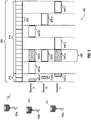
- FIG. 2 shows a block diagram of a design of a base station/eNB 105 and a UE 115, which may be one of the base stations/eNBs and one of the UEs in FIG. 1 .
- a transmit processor 220 may receive data from a data source 212 and control information from a controller/processor 240.
- the control information may be for the PBCH, PCFICH, PHICH, PDCCH, EPDCCH, MPDCCH etc.
- the data may be for the PDSCH, etc.
- the transmit processor 220 may process (e.g., encode and symbol map) the data and control information to obtain data symbols and control symbols, respectively.
- the transmit processor 220 may also generate reference symbols, e.g., for the PSS, SSS, and cell-specific reference signal.
- a transmit (TX) multiple-input multiple-output (MIMO) processor 230 may perform spatial processing (e.g., precoding) on the data symbols, the control symbols, and/or the reference symbols, if applicable, and may provide output symbol streams to the modulators (MODs) 232a through 232t.
- Each modulator 232 may process a respective output symbol stream (e.g., for OFDM, etc.) to obtain an output sample stream.
- Each modulator 232 may further process (e.g., convert to analog, amplify, filter, and upconvert) the output sample stream to obtain a downlink signal.
- Downlink signals from modulators 232a through 232t may be transmitted via the antennas 234a through 234t, respectively.
- the antennas 252a through 252r may receive the downlink signals from the eNB 105 and may provide received signals to the demodulators (DEMODs) 254a through 254r, respectively.
- Each demodulator 254 may condition (e.g., filter, amplify, downconvert, and digitize) a respective received signal to obtain input samples.
- Each demodulator 254 may further process the input samples (e.g., for OFDM, etc.) to obtain received symbols.
- a MIMO detector 256 may obtain received symbols from all the demodulators 254a through 254r, perform MIMO detection on the received symbols if applicable, and provide detected symbols.
- a receive processor 258 may process (e.g., demodulate, deinterleave, and decode) the detected symbols, provide decoded data for the UE 115 to a data sink 260, and provide decoded control information to a controller/processor 280.
- a transmit processor 264 may receive and process data (e.g., for the PUSCH) from a data source 262 and control information (e.g., for the PUCCH) from the controller/processor 280.
- the transmit processor 264 may also generate reference symbols for a reference signal.
- the symbols from the transmit processor 264 may be precoded by a TX MIMO processor 266 if applicable, further processed by the modulators 254a through 254r (e.g., for SC-FDM, etc.), and transmitted to the eNB 105.
- the uplink signals from the UE 115 may be received by the antennas 234, processed by the demodulators 232, detected by a MIMO detector 236 if applicable, and further processed by a receive processor 238 to obtain decoded data and control information sent by the UE 115.
- the processor 238 may provide the decoded data to a data sink 239 and the decoded control information to the controller/processor 240.
- the controllers/processors 240 and 280 may direct the operation at the eNB 105 and the UE 115, respectively.
- the controller/processor 240 and/or other processors and modules at the eNB 105 may perform or direct the execution of various processes for the techniques described herein.
- the controllers/processor 280 and/or other processors and modules at the UE 115 may also perform or direct the execution of the functional blocks illustrated in FIGs. 6 , 7 , and 10 , and/or other processes for the techniques described herein.
- the memories 242 and 282 may store data and program codes for the eNB 105 and the UE 115, respectively.
- a scheduler 244 may schedule UEs for data transmission on the downlink and/or uplink.
- Wireless communications systems operated by different network operating entities may share spectrum.
- a network operating entity may be configured to use an entirety of a designated shared spectrum for at least a period of time before another network operating entity uses the entirety of the designated shared spectrum for a different period of time.
- certain resources e.g., time
- a network operating entity may be allocated certain time resources reserved for exclusive communication by the network operating entity using the entirety of the shared spectrum.
- the network operating entity may also be allocated other time resources where the entity is given priority over other network operating entities to communicate using the shared spectrum.
- These time resources, prioritized for use by the network operating entity may be utilized by other network operating entities on an opportunistic basis if the prioritized network operating entity does not utilize the resources. Additional time resources may be allocated for any network operator to use on an opportunistic basis.
- Access to the shared spectrum and the arbitration of time resources among different network operating entities may be centrally controlled by a separate entity, autonomously determined by a predefined arbitration scheme, or dynamically determined based on interactions between wireless nodes of the network operators.
- UE 115 and base station 105 may operate in a shared radio frequency spectrum band, which may include licensed or unlicensed (e.g., contention-based) frequency spectrum.
- UEs 115 or base stations 105 may traditionally perform a medium-sensing procedure to contend for access to the frequency spectrum.
- UE 115 or base station 105 may perform a listen before talk (LBT) procedure such as a clear channel assessment (CCA) prior to communicating in order to determine whether the shared channel is available.
- LBT listen before talk
- CCA clear channel assessment
- a CCA may include an energy detection procedure to determine whether there are any other active transmissions.
- a device may infer that a change in a received signal strength indicator (RSSI) of a power meter indicates that a channel is occupied.
- RSSI received signal strength indicator
- a CCA also may include detection of specific sequences that indicate use of the channel.
- another device may transmit a specific preamble prior to transmitting a data sequence.
- an LBT procedure may include a wireless node adjusting its own backoff window based on the amount of energy detected on a channel and/or the acknowledge/negative-acknowledge (ACK/NACK) feedback for its own transmitted packets as a proxy for collisions.
- ACK/NACK acknowledge/negative-acknowledge
- base stations 105 and UEs 115 may be operated by the same or different network operating entities.
- an individual base station 105 or UE 115 may be operated by more than one network operating entity.
- each base station 105 and UE 115 may be operated by a single network operating entity. Requiring each base station 105 and UE 115 of different network operating entities to contend for shared resources may result in increased signaling overhead and communication latency.
- FIG. 3 illustrates an example of a timing diagram 300 for coordinated resource partitioning.
- the timing diagram 300 includes a superframe 305, which may represent a fixed duration of time (e.g., 20 ms).
- Superframe 305 may be repeated for a given communication session and may be used by a wireless system such as 5G network 100 described with reference to FIG. 1 .
- the superframe 305 may be divided into intervals such as an acquisition interval (A-INT) 310 and an arbitration interval 315.
- A-INT acquisition interval
- arbitration interval 315 As described in more detail below, the A-INT 310 and arbitration interval 315 may be subdivided into sub-intervals, designated for certain resource types, and allocated to different network operating entities to facilitate coordinated communications between the different network operating entities.
- the arbitration interval 315 may be divided into a plurality of sub-intervals 320.
- the superframe 305 may be further divided into a plurality of subframes 325 with a fixed duration (e.g., 1 ms). While timing diagram 300 illustrates three different network operating entities (e.g., Operator A, Operator B, Operator C), the number of network operating entities using the superframe 305 for coordinated communications may be greater than or fewer than the number illustrated in timing diagram 300.
- the A-INT 310 may be a dedicated interval of the superframe 305 that is reserved for exclusive communications by the network operating entities.
- each network operating entity may be allocated certain resources within the A-INT 310 for exclusive communications.
- resources 330-a may be reserved for exclusive communications by Operator A, such as through base station 105a
- resources 330-b may be reserved for exclusive communications by Operator B, such as through base station 105b
- resources 330-c may be reserved for exclusive communications by Operator C, such as through base station 105c. Since the resources 330-a are reserved for exclusive communications by Operator A, neither Operator B nor Operator C can communicate during resources 330-a, even if Operator A chooses not to communicate during those resources. That is, access to exclusive resources is limited to the designated network operator.
- the wireless nodes of Operator A may communicate any information desired during their exclusive resources 330-a, such as control information or data.
- a network operating entity When communicating over an exclusive resource, a network operating entity does not need to perform any medium sensing procedures (e.g., listen-before-talk (LBT) or clear channel assessment (CCA)) because the network operating entity knows that the resources are reserved. Because only the designated network operating entity may communicate over exclusive resources, there may be a reduced likelihood of interfering communications as compared to relying on medium sensing techniques alone (e.g., no hidden node problem).
- LBT listen-before-talk
- CCA clear channel assessment
- the A-INT 310 is used to transmit control information, such as synchronization signals (e.g., SYNC signals), system information (e.g., system information blocks (SIBs)), paging information (e.g., physical broadcast channel (PBCH) messages), or random access information (e.g., random access channel (RACH) signals).
- control information such as synchronization signals (e.g., SYNC signals), system information (e.g., system information blocks (SIBs)), paging information (e.g., physical broadcast channel (PBCH) messages), or random access information (e.g., random access channel (RACH) signals).
- SIBs system information blocks
- PBCH physical broadcast channel
- RACH random access channel
- resources may be classified as prioritized for certain network operating entities.
- Resources that are assigned with priority for a certain network operating entity may be referred to as a guaranteed interval (G-INT) for that network operating entity.
- G-INT guaranteed interval
- the interval of resources used by the network operating entity during the G-INT may be referred to as a prioritized sub-interval.
- resources 335-a may be prioritized for use by Operator A and may therefore be referred to as a G-INT for Operator A (e.g., G-INT-OpA).
- resources 335-b may be prioritized for Operator B
- resources 335-c may be prioritized for Operator C
- resources 335-d may be prioritized for Operator A
- resources 335-e may be prioritized for Operator B
- resources 335-f may be prioritized for operator C.
- the various G-INT resources illustrated in FIG. 3 appear to be staggered to illustrate their association with their respective network operating entities, but these resources may all be on the same frequency bandwidth. Thus, if viewed along a time-frequency grid, the G-INT resources may appear as a contiguous line within the superframe 305. This partitioning of data may be an example of time division multiplexing (TDM). Also, when resources appear in the same sub-interval (e.g., resources 340-a and resources 335-b), these resources represent the same time resources with respect to the superframe 305 (e.g., the resources occupy the same sub-interval 320), but the resources are separately designated to illustrate that the same time resources can be classified differently for different operators.
- TDM time division multiplexing
- a network operating entity When resources are assigned with priority for a certain network operating entity (e.g., a G-INT), that network operating entity may communicate using those resources without having to wait or perform any medium sensing procedures (e.g., LBT or CCA). For example, the wireless nodes of Operator A are free to communicate any data or control information during resources 335-a without interference from the wireless nodes of Operator B or Operator C.
- a certain network operating entity e.g., a G-INT
- that network operating entity may communicate using those resources without having to wait or perform any medium sensing procedures (e.g., LBT or CCA).
- LBT or CCA medium sensing procedures
- a network operating entity may additionally signal to another operator that it intends to use a particular G-INT. For example, referring to resources 335-a, Operator A may signal to Operator B and Operator C that it intends to use resources 335-a. Such signaling may be referred to as an activity indication. Moreover, since Operator A has priority over resources 335-a, Operator A may be considered as a higher priority operator than both Operator B and Operator C. However, as discussed above, Operator A does not have to send signaling to the other network operating entities to ensure interference-free transmission during resources 335-a because the resources 335-a are assigned with priority to Operator A.
- a network operating entity may signal to another network operating entity that it intends not to use a particular G-INT. This signaling may also be referred to as an activity indication.
- Operator B may signal to Operator A and Operator C that it intends not to use the resources 335-b for communication, even though the resources are assigned with priority to Operator B.
- Operator B may be considered a higher priority network operating entity than Operator A and Operator C. In such cases, Operators A and C may attempt to use resources of sub-interval 320 on an opportunistic basis.
- the sub-interval 320 that contains resources 335-b may be considered an opportunistic interval (O-INT) for Operator A (e.g., O-INT-OpA).
- O-INT opportunistic interval
- resources 340-a may represent the O-INT for Operator A.
- the same sub-interval 320 may represent an O-INT for Operator C with corresponding resources 340-b.
- Resources 340-a, 335-b, and 340-b all represent the same time resources (e.g., a particular sub-interval 320), but are identified separately to signify that the same resources may be considered as a G-INT for some network operating entities and yet as an O-INT for others.
- Operator A and Operator C may perform medium-sensing procedures to check for communications on a particular channel before transmitting data. For example, if Operator B decides not to use resources 335-b (e.g., G-INT-OpB), then Operator A may use those same resources (e.g., represented by resources 340-a) by first checking the channel for interference (e.g., LBT) and then transmitting data if the channel was determined to be clear.
- resources 335-b e.g., G-INT-OpB
- Operator C may perform a medium sensing procedure and access the resources if available.
- two operators e.g., Operator A and Operator C
- the operators may also have sub-priorities assigned to them designed to determine which operator may gain access to resources if more than operator is attempting access simultaneously.
- a network operating entity may intend not to use a particular G-INT assigned to it, but may not send out an activity indication that conveys the intent not to use the resources.
- lower priority operating entities may be configured to monitor the channel to determine whether a higher priority operating entity is using the resources. If a lower priority operating entity determines through LBT or similar method that a higher priority operating entity is not going to use its G-INT resources, then the lower priority operating entities may attempt to access the resources on an opportunistic basis as described above.
- access to a G-INT or O-INT may be preceded by a reservation signal (e.g., request-to-send (RTS)/clear-to-send (CTS)), and the contention window (CW) may be randomly chosen between one and the total number of operating entities.
- a reservation signal e.g., request-to-send (RTS)/clear-to-send (CTS)
- CW contention window
- an operating entity may employ or be compatible with coordinated multipoint (CoMP) communications.
- CoMP coordinated multipoint
- an operating entity may employ CoMP and dynamic time division duplex (TDD) in a G-INT and opportunistic CoMP in an O-INT as needed.
- TDD dynamic time division duplex
- each sub-interval 320 includes a G-INT for one of Operator A, B, or C.
- one or more sub-intervals 320 may include resources that are neither reserved for exclusive use nor reserved for prioritized use (e.g., unassigned resources). Such unassigned resources may be considered an O-INT for any network operating entity, and may be accessed on an opportunistic basis as described above.
- each subframe 325 may contain 14 symbols (e.g., 250- ⁇ s for 60 kHz tone spacing). These subframes 325 may be standalone, self-contained Interval-Cs (ITCs) or the subframes 325 may be a part of a long ITC.
- An ITC may be a self-contained transmission starting with a downlink transmission and ending with a uplink transmission.
- an ITC may contain one or more subframes 325 operating contiguously upon medium occupation. In some cases, there may be a maximum of eight network operators in an A-INT 310 (e.g., with duration of 2 ms) assuming a 250- ⁇ s transmission opportunity.
- each sub-interval 320 may be occupied by a G-INT for that single network operating entity, or the sub-intervals 320 may alternate between G-INTs for that network operating entity and O-INTs to allow other network operating entities to enter.
- the sub-intervals 320 may alternate between G-INTs for the first network operating entity and G-INTs for the second network operating entity. If there are three network operating entities, the G-INT and O-INTs for each network operating entity may be designed as illustrated in FIG. 3 . If there are four network operating entities, the first four sub-intervals 320 may include consecutive G-INTs for the four network operating entities and the remaining two sub-intervals 320 may contain O-INTs. Similarly, if there are five network operating entities, the first five sub-intervals 320 may contain consecutive G-INTs for the five network operating entities and the remaining sub-interval 320 may contain an O-INT. If there are six network operating entities, all six sub-intervals 320 may include consecutive G-INTs for each network operating entity. It should be understood that these examples are for illustrative purposes only and that other autonomously determined interval allocations may be used.
- the coordination framework described with reference to FIG. 3 is for illustration purposes only.
- the duration of superframe 305 may be more or less than 20 ms.
- the number, duration, and location of sub-intervals 320 and subframes 325 may differ from the configuration illustrated.
- the types of resource designations e.g., exclusive, prioritized, unassigned
- CoMP coordinated multipoint
- CoMP generally falls into two major categories: joint processing, where there is coordination between multiple entities - base stations - that are simultaneously transmitting or receiving to or from UEs; and coordinated scheduling or beamforming, where a UE transmits with a single transmission or reception point, while the communication is made with an exchange of control among several coordinated entities.
- the joint processing form of CoMP also includes a subclass referred to as joint transmission, in which UE data is simultaneously processed and transmitted from multiple cooperating base stations. In heterogeneous and dense small cell network scenarios with low power nodes, UEs may experience significant signal strength simultaneously from multiple base stations.
- accurate and up-to-date channel state information (CSI) feedback is used.
- the uplink and downlink transmissions take place over the same frequency band. Therefore, when the transmissions are performed within the channel coherence time, the uplink and downlink channel states are generally the same.
- the downlink channel to each user ideally can be estimated in the uplink direction by base stations receiving transmission of sounding reference signals (SRS) from the user equipment (UEs).
- SRS sounding reference signals
- UEs user equipment
- the estimated downlink channel may then be used in the design of downlink beams.
- reciprocity is not perfect.
- each node may introduce a mismatch, such as through an amplitude and/or a phase perturbation, to the transmitted/received signals because the transceiver radio frequency (RF) chains (e.g. antennas, RF mixers and filters, analog-to-digital (A/D) convertors, in-phase/quadrature (I/Q) imbalances, etc.) are not necessarily identical across different nodes/antennas.
- RF radio frequency
- Calibration may be performed to identify the mismatch between the downlink and uplink channels and then applied on the channel estimation from the SRS transmission.
- CoMP Coordinated multipoint
- the joint processing form of CoMP also includes a subclass referred to as joint transmission, in which UE data is simultaneously processed and transmitted from multiple cooperating base stations.
- the various aspects of the present disclosure are directed to downlink CoMP joint transmission, in which each of the beams is transmitted from multiple geographically separated eNBs.
- CoMP joint transmission generally uses centralized processing at a central eNB with fiber backhaul connections to the other coordinating eNBs.
- Downlink CoMP joint transmission is analogous to a large scale MIMO system with geographically distributed eNBs and UEs.
- This processes uses accurate channel knowledge for accurate beam pointing (more precisely, beam nulling toward unintended UEs).
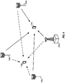
- FIG. 4 is a block diagram illustrating a CoMP operation involving eNBs 105a-105d serving UE 115b.
- eNBs 105a-105d form the CoMP set serving UE 115b through joint transmission.
- eNBs 105a-105d coordinate beamforming for communications in such a manner that UE 115b sees the signal.
- the beams are coordinated to nullify the net signal toward unintended UEs, such as UE 115a, as much as possible. Therefore, the combined signal from eNBs 105a-105d seen at UE 115a is very small, as the signals from eNBs 105a-105d are constructed cancel each other out at unintended UE 115a.
- CoMP performance may be very sensitive to phase mismatch.
- Beam nulling e.g., zero forcing
- UE 115a unintended UEs, such as UE 115a
- eNBs 105a-105d e.g., eNBs 105a-105d.
- a phase error within 3 degrees ( ⁇ /64 rad) may be used to deliver 20 dB SINR to most of the UEs.
- calibration may be performed to determine the mismatch between the downlink and uplink channels and then applied on the channel estimation obtained based on the received SRS transmission.
- calibration would be performed within each device between different antennas, while in CoMP, calibration would be performed across all antennas of the cooperating nodes.
- Calibration in CoMP operations results in removal of the gain/phase mismatch between the downlink and uplink among antennas within the eNB and across the cooperating eNBs.
- this calibration (which calibrates the gain and phase), the phases at different eNBs may drift over time.
- phase synchronization may be performed regularly to achieve a short term co-phasing of eNBs.
- FIG. 5 is a block diagram illustrating a CoMP operation between eNBs 105a-105c and UE 115a. Calibration may be performed infrequently, while phase synchronization may be performed before each CoMP LBT frame. For example, calibration 500 and 501 occur periodically over multiple CoMP LBT frames, while phase synchronization, such as phase synchronization 502, occurs at the beginning of each CoMP LBT frame, such as CoMP LBT frame 503.
- Relative timing drift between a UE and an eNB due to time-to-live (TTL) and timing adjustment (TA) may create a linear phase ramp in the frequency domain.
- This phase ramp may have no impact on signal-to-leakage ratio (SLR) beamforming, but it may create challenges for phase estimation, calibration, and synchronization.
- Clock drift across various transmission points (TPs) may create a linear phase ramp in the frequency domain (per TP) that may be corrected via phase synchronization.
- phase continuity continuity may be guaranteed at an eNB, but is not necessary at a UE.
- Various aspects of the present disclosure are directed to performing over-the-air phase synchronization for reciprocity-based CoMP joint transmission.
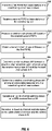
- FIG. 6 is a block diagram illustrating example blocks executed to implement one aspect of the present disclosure. The example blocks will also be described with respect to base station 105 as illustrated in FIG. 13.
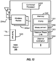
- FIG. 13 is a block diagram illustrating base station 105 configured according to one aspect of the present disclosure.
- Base station 105 includes the structure, hardware, and components as illustrated for base station 105 of FIG. 2 .
- base station 105 includes controller/processor 240, which operates to execute logic or computer instructions stored in memory 242, as well as controlling the components of base station 105 that provide the features and functionality of base station 105.
- Base station 105 under control of controller/processor 240, transmits and receives signals via wireless radios 1300a-t and antennas 234a-t.
- Wireless radios 1300a-t includes various components and hardware, as illustrated in FIG. 2 for base station 105, including modulator/demodulators 232a-t, MIMO detector 236, receive processor 238, transmit processor 220, and TX MIMO processor 230.
- a first PSRS is transmitted from base stations of a coordinating set of base stations.
- base station 105 under control of controller/processor 240, generates the first PSRS using PSRS logic 1301, stored in memory 242.
- the generated first PSRS would then be transmitted by base station 105 via wireless radios 1300a-t and antennas 234a-t.
- the transmission of such first PSRS will be used in determining a phase drift in the transmit chain of those base stations, including base station 105, transmitting the first PSRS.
- a second PSRS is received at base stations of the coordinating set.
- base station 105 receives the second PSRS.
- the second PSRS is used by the receiving base stations, including base station 105, to determine the phase drift in the receive chain of those base stations.
- the second PSRS may be an uplink PSRS transmitted by a served UE (UE-assisted) and received by base station 105 via antennas 234a-t and wireless radios 1300, or may be a PSRS transmitted by another group of eNBs within the CoMP set (inter-eNB) and received via backhaul 1305 (either wired or wirelessly).
- the first PSRS would be transmitted by one group of eNBs in the CoMP set different from the second group transmitting the second PSRS.
- the base station measures the receive chain phase drift based on the second PSRS.
- base station 105 executes measurement logic 1302, stored in memory 242.
- the execution environment of measurement logic 1302 allows base station 105 to measure the phase drift of the signal of the second PSRS.
- the subject base station obtains a transmit chain phase drift based on the first PSRS that it transmitted.
- the transmit chain phase drift may be obtained in varying ways depending on the example aspect implemented.
- the UEs receiving the first PSRS estimate the downlink channel and may signal that downlink estimate back to base station 105 either directly through an uplink signal (e.g., PUCCH, PUSCH) or indirectly by modulating the second PSRS, which is transmitted by the UE, using the phase and/or amplitude of the downlink channel estimate.
- Base station would receive such transmit chain phase drift via wireless radios 1300a-t and antennas 234a-t.
- the noted second group of base stations of the CoMP set receives the first PSRS and determines the downlink channel estimate that is then communicated the central base station, base station 105, of the CoMP set via backhaul 1305.
- the subject base station determines a relative phase drift between the downlink channel and the uplink channel using the receive chain and transmit chain phase drifts.
- base station 105 under control of controller/processor 240, executes relative phase drift logic 1303, stored in memory 242.
- the execution environment of relative phase drift logic 1303 allows for base station 105 to determine the relative phase drift logic between the uplink and downlink channels.
- the central eNB such as base station 105, collects the channel estimates from the first group of eNBs (which estimate the channel based on the second PSRS transmitted by the second group of eNBs) and the second group of eNBs (which estimate the channel based on the first PSRS transmitted by the first group of eNBs).
- the central eNB e.g., base station 105) may then determine the relative phase drift between the downlink and uplink channels within the execution environment of relative phase drift logic 1303.
- the subject base station determines a relative coordinating phase drift among all cooperating base stations in a coordinating set of base stations. With the phase drifts determined between the uplink and downlink channels at the base station, a relative phase drift may then be determined among all of the base stations of the CoMP set. For example, within the execution environment of relative phase drift logic 1303, base station 105 may also use the relative phase drifts at the other base stations of the CoMP set to determine the relative coordinating phase drift. This provides information regarding the relative association among such base stations.
- the subject base station generates an uplink channel estimate based on SRS received from the served UEs, and, at block 607, generates the downlink channel estimate based on the uplink channel estimate compensated with the relative phase drift and relative coordinating phase drift.
- base station 105 under control of controller/processor 240, executes channel estimation logic 1304, stored in memory 242. the execution environment of channel estimation logic 1304 provides the functionality to determine channel estimate for the uplink and downlink channels.
- base station 105 uses the relative phase drift between all of the base stations of the CoMP set to generate the downlink channel estimate from the uplink channel estimate, thus, compensating for the phase drift and preserving the reciprocity of channels. Therefore, the phase may be synchronized through transmission, reception, and analysis of different PSRS.
- phase synchronization may be assisted via UE signaling (UE-assisted), while a second example aspect provides phase synchronization via signaling among the coordinating eNBs (inter-eNB).
- the channel estimates and phase offsets may be determined by a variety of algorithms or methods well known in wireless communications. The various aspects of the present disclosure are not limited to any single algorithm or set of algorithms for estimating the downlink and uplink channels and obtaining the phase offsets between the channel estimates.
- FIG. 7 is a block diagram illustrating example blocks executed to implement a UE-assisted aspect of the present disclosure.
- the various operations that implement the UE-assisted aspect of the present disclosure follow the general operations described with respect to FIG. 6 .
- the blocks described in FIG. 7 provide additional detail of the operations that are used to specifically implement the UE-assisted aspect.
- the example blocks will also be described with respect to base station 105 as illustrated in FIG. 13 .
- the first PSRS transmitted by the base stations of a coordinating set of base stations is transmitted to served UEs.
- Each base station, such as base station 105, in the CoMP set transmits the first PSRS generated within the execution environment of PSRS logic 1301.
- the second PSRS received at the base stations of the coordinating set are received from the served UEs.
- the second PSRS is received by base station 105 from the served UEs via antennas 234a-t and wireless radios 1300a-t.
- the UEs transmit the second, uplink PSRS to the base stations of the CoMP set which, at block 702, measure the receive chain phase drift based on the received second PSRS.
- Base station 105 uses the received uplink PSRS within the execution environment of measurement logic 1302 to measure the phase drift in the receive chain.
- the base station obtains the transmit chain phase drift based on the first PSRS received by the served UEs.
- the UEs receive the first or downlink PSRS, estimate the downlink channel based on the first PSRS and then communicate the estimated downlink channel back to base station 105.
- This communication of the estimated downlink channel may be made directly, such as through a reporting signal (PUCCH or PUSCH), or indirectly, such as by modulating the uplink PSRS according to the measured or detected phase and/or magnitude of the estimated downlink channel.
- Base station 105 would then either directly receive the estimated downlink channel or determine the estimated downlink channel through demodulation of the uplink PSRS and within the execution environment of channel estimation logic 1304.
- Base station 105 uses the downlink channel estimated to determine the transmit chain phase drift. Therefore, once base station 105 obtains the transmit chain phase drift, the phase may be synchronized according to the remaining blocks in FIG. 6 .
- FIG. 8 is a block diagram illustrating CoMP operation 80 configured according to one aspect of the present disclosure.
- CoMP operation 80 supports communications between eNBs 105a-105c and UE 115a.
- the transmission channel is reserved by eNBs 105a-105c during reservation preamble 800.
- An LBT procedure may be performed within reservation preamble 800 in order to secure the channel.
- eNBs 105a-105c transmit downlink phase-synchronization reference signals (DL-PSRS) 802 which enable each UE, such as UE 115a, to estimate the downlink channel between UE 115a and of each of eNBs 105a-105c.
- DL-PSRS downlink phase-synchronization reference signals
- the UEs such as UE 115a, would then transmit uplink (PSRS) (UL-PSRS) 803 that enable each of eNBs 105a-105c to measure the phase drift caused by the receiver chain at each eNB.
- eNBs 105a-105c obtain the downlink channel estimate from UE 115a either directly, via signaling (e.g., PUCCH, PUSCH), or indirectly, via UE 115a modulating UL-PSRS 803 by the estimated downlink channel phase and/or magnitude.
- eNBs 105a-105c may determine the phase drift of the transmit chain.
- eNBs 105a-105c may then compute an estimate of the phase drift between the downlink and uplink channel.
- the estimated phase drift can be applied on the uplink channel estimate determined using the SRS transmitted from UE 115a in order to translate the uplink channel estimate into a downlink channel estimate, thus, compensating and preserving the channel reciprocity.
- UE 115a may estimate the downlink channel using DL-PSRS 802 tones and then transmit the estimated downlink channel on an uplink channel (e.g., PUCCH or PUSCH) to eNBs 105a-105c. While this procedure allows eNBs 105a-105c to directly obtain an accurate downlink channel estimate from the UE, which eNBs 105a-105c may then use to determine the transmit chain phase drift, it makes use of large feedback overhead, and the processing time at the eNB to decode this PUCCH/PUSCH may ultimately delay CoMP transmission.
- PUCCH or PUSCH uplink channel
- UE 115a may estimate the downlink channel using DL-PSRS tones 802 and then use the phase and/or magnitude of the estimated channel to modulate UL-PSRS tones 803.
- the modulation may be a modulation using the actual phase and/or magnitude of the downlink estimate or may be a modulation using the negative of the phase observed on DL-PSRS 802 (e.g., "analog feedback") or an inverse of the downlink estimate.
- the subject eNB any of eNBs 105a-105c, may then obtain the UE-determined estimated downlink channel and directly observe the net phase difference or drift between the eNB receiver and eNB transmitter chains.
- phase synchronization may be performed at CoMP header 801 at the beginning of each CoMP LBT frame 804, including CoMP header 801 and downlink/uplink CoMP data burst 805.
- CoMP header 801 according to the UE-assisted aspect of the present disclosure generally contains downlink "pre-grant" SRS/channel state feedback (CSF) requests, DL-PSRS 802, and uplink "pre-grant ACK" SRS and CSF (PUCCH) responses, in addition to UL-PSRS 803.
- Phase synchronization by eNBs 105a-105c may be based on DL-PSRS 802 and UL-PSRS 803 contained in CoMP header 801.
- UE 115a may modulate UL-PSRS 803 using the channel estimates based on DL-PSRS 802 to provide an analog feedback of downlink channel estimate and transmit SRS unmodulated.
- FIG. 9 is a block diagram illustrating a CoMP operation between eNBs 0-3 and UEs 0-2 configured according to one aspect of the present disclosure.
- the UE-assisted phase synchronization aspect of the present disclosure may include various options for design of the uplink and downlink PSRS.
- a first alternative option may include one or multiple DL-PSRS symbols 802 and, on the uplink, one UL-PSRS symbol 803 and one or multiple unmodulated SRS symbols 900.
- Unmodulated SRS 900 may be used to perform the downlink/uplink channel estimation.
- DL-PSRS 802 from different eNBs 0-3 are multiplexed in transmission, while UL-PSRS 803 from different UEs 0-2 are multiplexed in such a way that all the eNB-UE pairs are accounted for in the multiplexed transmission.
- eNB0 transmits a DL-PSRS tone and UE0 sends a UL-PSRS tone modulated by the estimated downlink channel from eNB0.
- the downlink channel may be estimated using various methods, including a normalized conjugation of the estimated downlink channel from eNB0, a negative phase of the estimated downlink channel from eNB0, an inverse of the estimated downlink channel, or the like. eNB0 may then receive both uplink channel estimate and downlink channel estimate from UE0 in the same tone.
- UL-PSRS 803 are used to feed back the downlink channel estimation in order to reduce overhead.
- UEs 0-2 modulate UL-PSRS 803 with the conjugation of the normalized downlink channel estimation, while in a second alternative, UEs 0-2 modulates UL-PSRS 803 with the negate of the phase of the downlink channel estimation or, alternatively, an inverse of the downlink channel estimation.
- FIG. 10 is a block diagram illustrating example blocks executed to implement one aspect of the present disclosure.
- a first PSRS is transmitted from base stations in a first group of base stations in a coordinating set.
- the base stations of the CoMP set are divided into two groups.
- the first group as indicated in block 1000, transmit the first PSRS.
- the base stations of the first group receive a second PSRS from a second group of base stations in the coordinating set.
- the base stations receiving the second PSRS estimate the channel experienced by the second PSRS.
- the channel estimate may be communicated to a central eNB of the CoMP set.
- the subject base stations obtain a transmit chain phase drift calculated on the first PSRS received by the second group.
- the second group base stations make an estimate of the downlink channel based on the first PSRS.
- This downlink estimate may be communicated to the central eNB, which collects the estimated channel from each of the base stations in the first and second groups.
- the central eNB may then determine the relative phase drift based on the channel estimates it collects from the other eNBs of the CoMP set.
- one group of eNBs transmit PSRS for the other eNBs (inter-eNB), while a group of the other eNBs transmits PSRS to the first group of eNBs.
- the central eNB of the CoMP set may then compute the phase drift using the two directions of PSRS.
- the estimated phase drift can then be applied on the uplink channel estimate obtained using the SRS from the UEs to translate the estimated uplink channel into a downlink channel estimate.
- the resulting downlink channel estimate compensates for the phase drift and preserves the reciprocity between the uplink and downlink channels.
- FIG. 11 is a block diagram illustrating a CoMP operation 1100 between eNBs 105a-105c and UE 115a configured according to one aspect of the present disclosure.
- the phase synchronization may be also performed at CoMP header 1105 at the beginning of each CoMP LBT frame 1104.
- CoMP LBT frame 1104 includes both CoMP header 1105 and downlink/uplink CoMP data burst 1106.
- phase synchronization may be based on two-phase PSRS exchanges, Inter-eNB PSRS 1102 and 1103, among various eNBs 105a-105c of the CoMP set prior to CoMP header 1105, thus, it is transparent to UE 115a.
- CoMP header 1105 may generally contain the inter-eNB phase exchange of inter-eNB PSRS 1102 and 1103, the DL "pre-grant" SRS/CSF request, CSI-RS, and the uplink "pre-grant ACK" SRS and CSF (PUCCH) response.
- eNBs 105a-105c of the CoMP set are divided into two groups. In each phase, one group of eNBs (e.g., 105a and 105b) transmits inter-eNB PSRS 1102, while the other group of eNBs (e.g., 105c) receives inter-eNB PSRS 1102 to estimate the channel.
- This second group of eNBs (e.g., eNB 105c) then sends its own inter-eNB PSRS 1103, which the first group of eNBs (e.g, eNBs 105a and 105b) may then use for determining the channel estimate.
- These estimates are communicated to a central eNB (e.g., one of eNBs 105a-105c) which may then determine the phase offset for the estimates on both directions/channels.
- FIG. 12 is a block diagram illustrating a CoMP operation between eNBs 0-3 and UEs 0-2 configured according to one aspect of the present disclosure.
- the first group of eNBs, eNBs 0-3, sends inter-eNB PSRS 1102, which the second group of eNBs (not shown) uses to estimate the channel in that direction (from the first group to the second group).
- This direction may be referred to, for convenience, as the "downlink" direction.
- the second group of the eNBs then send inter-eNB PSRS which the first group of eNBs, eNBs 0-3, use to estimate the channel in that direction (from the second group to the first group).
- This direction may be referred to, for convenience, as the uplink direction.
- the central eNB, eNB2 will then receive channels on both directions and determine the phase offset. Thus, no feedback is needed.
- eNB2 may estimate the uplink channel based on UL-SRS 1200 received from UEs 0-2 and, may apply to phase offset of the uplink channel estimated to obtain the downlink channel estimate.
- the functional blocks and modules in FIGs. 6 , 7 , and 10 may comprise processors, electronics devices, hardware devices, electronics components, logical circuits, memories, software codes, firmware codes, etc., or any combination thereof.
- DSP digital signal processor
- ASIC application specific integrated circuit
- FPGA field programmable gate array
- a general-purpose processor may be a microprocessor, but in the alternative, the processor may be any conventional processor, controller, microcontroller, or state machine.
- a processor may also be implemented as a combination of computing devices, e.g., a combination of a DSP and a microprocessor, a plurality of microprocessors, one or more microprocessors in conjunction with a DSP core, or any other such configuration.
- a software module may reside in RAM memory, flash memory, ROM memory, EPROM memory, EEPROM memory, registers, hard disk, a removable disk, a CD-ROM, or any other form of storage medium known in the art.
- An exemplary storage medium is coupled to the processor such that the processor can read information from, and write information to, the storage medium.
- the storage medium may be integral to the processor.
- the processor and the storage medium may reside in an ASIC.
- the ASIC may reside in a user terminal.
- the processor and the storage medium may reside as discrete components in a user terminal.
- the functions described may be implemented in hardware, software, firmware, or any combination thereof. If implemented in software, the functions may be stored on or transmitted over as one or more instructions or code on a computer-readable medium.
- Computer-readable media includes both computer storage media and communication media including any medium that facilitates transfer of a computer program from one place to another. Computer-readable storage media may be any available media that can be accessed by a general purpose or special purpose computer.
- such computer-readable media can comprise RAM, ROM, EEPROM, CD-ROM or other optical disk storage, magnetic disk storage or other magnetic storage devices, or any other medium that can be used to carry or store desired program code means in the form of instructions or data structures and that can be accessed by a general-purpose or special-purpose computer, or a general-purpose or special-purpose processor.
- a connection may be properly termed a computer-readable medium.
- the software is transmitted from a website, server, or other remote source using a coaxial cable, fiber optic cable, twisted pair, or digital subscriber line (DSL), then the coaxial cable, fiber optic cable, twisted pair, or DSL, are included in the definition of medium.
- DSL digital subscriber line
- Disk and disc includes compact disc (CD), laser disc, optical disc, digital versatile disc (DVD), floppy disk and blu-ray disc where disks usually reproduce data magnetically, while discs reproduce data optically with lasers. Combinations of the above should also be included within the scope of computer-readable media.
- the term "and/or,” when used in a list of two or more items, means that any one of the listed items can be employed by itself, or any combination of two or more of the listed items can be employed.
- the composition can contain A alone; B alone; C alone; A and B in combination; A and C in combination; B and C in combination; or A, B, and C in combination.
Landscapes
- Engineering & Computer Science (AREA)
- Computer Networks & Wireless Communication (AREA)
- Signal Processing (AREA)
- Power Engineering (AREA)
- Mobile Radio Communication Systems (AREA)
Claims (15)
- Verfahren zur drahtlosen Kommunikation, umfassend:Senden (600), durch eine Basisstation, eines ersten Phasensynchronisationsreferenzsignals, PSRS, wobei die Basisstation eine von einer Mehrzahl von kooperierenden Basisstationen in einem koordinierenden Satz von Basisstationen ist;Empfangen (601), an der Basisstation, eines zweiten PSRS;Messen (602), an der Basisstation, eines Empfangskettenphasendrifts basierend auf dem empfangenen zweiten PSRS;Erhalten (603), an der Basisstation, eines Sendekettenphasendrifts basierend auf dem ersten PSRS;Bestimmen (604), durch die Basisstation, eines relativen Phasendrifts zwischen einem Downlink-Kanal und einem Uplink-Kanal unter Verwendung des Empfangskettenphasendrifts und des Sendekettenphasendrifts;Bestimmen (605), durch die Basisstation, eines relativen koordinierenden Phasendrifts unter allen kooperierenden Basisstationen im koordinierenden Satz von Basisstationen;Erzeugen (606), durch die Basisstation, einer Uplink-Kanalschätzung basierend auf einem Sondierungsreferenzsignal, SRS, das von einem Benutzergerät, UE, empfangen wird; undErzeugen (607), durch die Basisstation, einer Downlink-Kanalschätzung basierend auf der Uplink-Kanalschätzung, dem relativen Phasendrift und dem relativen koordinierenden Phasendrift.
- Verfahren nach Anspruch 1,wobei das zweite PSRS vom UE empfangen wird, undwobei das Erhalten des Sendekettenphasendrifts das Erhalten des Sendekettenphasendrifts vom UE einschließt.
- Verfahren nach Anspruch 2, wobei das Erhalten des Sendekettenphasendrifts vom UE einschließt:Empfangen eines Uplink-Signals vom UE, wobei das Uplink-Signal eine Downlink-Kanalschätzung vom UE basierend auf dem ersten PSRS einschließt; undBestimmen des Sendekettenphasendrifts basierend auf der Downlink-Kanalschätzung vom UE.
- Verfahren nach Anspruch 2, wobei das Erhalten des Sendekettenphasendrifts vom UE einschließt:Bestimmen einer Modulation des zweiten PSRS, wobei die Modulation des zweiten PSRS eines oder beides einschließt von: einer Phase und einer Größe einer Downlink-Kanalschätzung vom UE basierend auf dem ersten PSRS; undBestimmen des Sendekettenphasendrifts unter Verwendung der bestimmten Modulation.
- Verfahren nach Anspruch 4, wobei die Modulation eines einschließt von:einem Konjugat einer normalisierten Version der Downlink-Kanalschätzung;einem Negativ einer Phase der Downlink-Kanalschätzung; odereinem Inversen der Downlink-Kanalschätzung.
- Verfahren nach Anspruch 2,
wobei das Senden des ersten PSRS einschließt:Multiplexen des ersten PSRS der Basisstation mit einem oder mehreren zusätzlichen Downlink-PSRS, die von einer oder mehreren anderen Basisstationen des koordinierenden Satzes von Basisstationen gesendet werden, undwobei das Empfangen des zweiten PSRS einschließt:Empfangen des zweiten PSRS, das mit einem oder mehreren der Folgenden gemultiplext wird:einem oder mehreren zusätzlichen zweiten PSRS vom UE, undeinem oder mehreren zusätzlichen Uplink-PSRS von einem oder mehreren anderen UEs,wobei jedes des zweiten PSRS, eines oder mehrerer zusätzlicher zweiter PSRS und eines oder mehrerer zusätzlicher Uplink-PSRS moduliert werden gemäß einem oder mehreren von:der Downlink-Kanalschätzung, odereiner oder mehreren zusätzlichen Downlink-Kanalschätzungen, die bestimmt werden aus einem von: dem ersten PSRS oder dem einen oder den mehreren zusätzlichen Downlink-PSRS. - Verfahren nach Anspruch 1,wobei das erste PSRS zusammen mit anderen ersten PSRS von einer ersten Gruppe von Basisstationen im koordinierenden Satz von Basisstationen gesendet wird, undwobei das zweite PSRS von einer zweiten Gruppe von Basisstationen im koordinierenden Satz von Basisstationen empfangen wird, die sich von der ersten Gruppe von Basisstationen unterscheidet, undwobei das Erhalten des Sendekettenphasendrifts einschließt:Empfangen, an der Basisstation, einer ersten Kanalschätzung von der ersten Gruppe von Basisstationen basierend auf dem ersten PSRS und einer zweiten Kanalschätzung von der zweiten Gruppe von Basisstationen basierend auf dem zweiten PSRS, wobei die Basisstation eine zentrale Basisstation des koordinierenden Satzes von Basisstationen ist; undBestimmen des relativen koordinierenden Phasendrifts unter allen Basisstationen des koordinierenden Satzes von Basisstationen.
- Verfahren nach Anspruch 7, wobei das Senden des ersten PSRS einschließt:Multiplexen des ersten PSRS mit dem anderen ersten PSRS, undwobei das Empfangen des zweiten PSRS einschließt:
Empfangen des zweiten PSRS, das mit anderen zweiten PSRS von der zweiten Gruppe von Basisstationen gemultiplext wird. - Vorrichtung, die zur drahtlosen Kommunikation konfiguriert ist, umfassend:Mittel zum Senden (600) eines ersten Phasensynchronisationsreferenzsignals, PSRS, wobei die Vorrichtung eine von einer Mehrzahl von kooperierenden Basisstationen in einem koordinierenden Satz von Basisstationen ist;Mittel zum Empfangen (601) eines zweiten PSRS;Mittel zum Messen (602) eines Empfangskettenphasendrifts basierend auf dem empfangenen zweiten PSRS;Mittel zum Erhalten (603) eines Sendekettenphasendrifts basierend auf dem ersten PSRS;Mittel zum Bestimmen (604) eines relativen Phasendrifts zwischen einem Downlink-Kanal und einem Uplink-Kanal unter Verwendung des Empfangskettenphasendrifts und des Sendekettenphasendrifts;Mittel zum Bestimmen (605) eines relativen koordinierenden Phasendrifts unter allen kooperierenden Basisstationen im koordinierenden Satz von Basisstationen;Mittel zum Erzeugen (606) einer Uplink-Kanalschätzung basierend auf einem Sondierungsreferenzsignal, SRS, das von einem Benutzergerät, UE, empfangen wird; undMittel zum Erzeugen (607) einer Downlink-Kanalschätzung basierend auf der Uplink-Kanalschätzung, dem relativen Phasendrift und dem relativen koordinierenden Phasendrift.
- Vorrichtung nach Anspruch 9,wobei das zweite PSRS vom UE empfangen wird, undwobei das Mittel zum Erhalten des Sendekettenphasendrifts Mittel zum Erhalten des Sendekettenphasendrifts vom UE einschließt.
- Vorrichtung nach Anspruch 10, wobei das Mittel zum Erhalten des Sendekettenphasendrifts vom UE einschließt:Mittel zum Empfangen eines Uplink-Signals vom UE, wobei das Uplink-Signal eine Downlink-Kanalschätzung vom UE basierend auf dem ersten PSRS einschließt; undMittel zum Bestimmen des Sendekettenphasendrifts basierend auf der Downlink-Kanalschätzung vom UE.
- Vorrichtung nach Anspruch 10, wobei das Mittel zum Erhalten des Sendekettenphasendrifts vom UE einschließt:Mittel zum Bestimmen einer Modulation des zweiten PSRS, wobei die Modulation des zweiten PSRS eines oder beides einschließt von: einer Phase und einer Größe einer Downlink-Kanalschätzung vom UE basierend auf dem ersten PSRS; undMittel zum Bestimmen des Sendekettenphasendrifts unter Verwendung der bestimmten Modulation.
- Vorrichtung nach Anspruch 9,wobei das erste PSRS zusammen mit anderen ersten PSRS von einer ersten Gruppe von Basisstationen im koordinierenden Satz von Basisstationen gesendet wird, undwobei das zweite PSRS von einer zweiten Gruppe von Basisstationen im koordinierenden Satz von Basisstationen empfangen wird, die sich von der ersten Gruppe von Basisstationen unterscheidet, undwobei das Mittel zum Erhalten des Sendekettenphasendrifts einschließt:Mittel zum Empfangen einer ersten Kanalschätzung von der ersten Gruppe von Basisstationen basierend auf dem ersten PSRS und einer zweiten Kanalschätzung von der zweiten Gruppe von Basisstationen basierend auf dem zweiten PSRS, wobei die Vorrichtung eine zentrale Basisstation des koordinierenden Satzes von Basisstationen ist; undMittel zum Bestimmen des relativen koordinierenden Phasendrifts unter allen Basisstationen des koordinierenden Satzes von Basisstationen.
- Vorrichtung nach Anspruch 13, wobei das Mittel zum Senden des ersten PSRS einschließt:Mittel zum Multiplexen des ersten PSRS mit dem anderen ersten PSRS, undwobei das Mittel zum Empfangen des zweiten PSRS einschließt:
Mittel zum Empfangen des zweiten PSRS, das mit anderen zweiten PSRS von der zweiten Gruppe von Basisstationen gemultiplext wird. - Computerprogramm, umfassend Anweisungen, die, wenn das Programm von einem Computer ausgeführt wird, den Computer veranlassen, das Verfahren nach einem der Ansprüche 1-8 auszuführen.
Applications Claiming Priority (3)
| Application Number | Priority Date | Filing Date | Title |
|---|---|---|---|
| US201662432179P | 2016-12-09 | 2016-12-09 | |
| US15/830,821 US10117207B2 (en) | 2016-12-09 | 2017-12-04 | Over-the-air phase synchronization for reciprocity-based comp joint transmission |
| PCT/US2017/064615 WO2018106634A1 (en) | 2016-12-09 | 2017-12-05 | Over-the-air phase synchronization for reciprocity-based comp joint transmission |
Publications (2)
| Publication Number | Publication Date |
|---|---|
| EP3552442A1 EP3552442A1 (de) | 2019-10-16 |
| EP3552442B1 true EP3552442B1 (de) | 2022-10-05 |
Family
ID=62489987
Family Applications (1)
| Application Number | Title | Priority Date | Filing Date |
|---|---|---|---|
| EP17818390.1A Active EP3552442B1 (de) | 2016-12-09 | 2017-12-05 | Ota-phasensynchronisation für reziprozitätsbasierte gemeinsame comp-übertragung |
Country Status (5)
| Country | Link |
|---|---|
| US (1) | US10117207B2 (de) |
| EP (1) | EP3552442B1 (de) |
| CN (1) | CN110024453B (de) |
| TW (1) | TW201831007A (de) |
| WO (1) | WO2018106634A1 (de) |
Families Citing this family (12)
| Publication number | Priority date | Publication date | Assignee | Title |
|---|---|---|---|---|
| US10616839B2 (en) * | 2017-04-27 | 2020-04-07 | Qualcomm Incorporated | Over-the-air phase synchronizatin for reciprocity-based comp joint transmission |
| US11552828B2 (en) | 2018-05-04 | 2023-01-10 | Semiconductor Components Industries, Llc | Beamformer solicited sounding |
| US11394441B2 (en) * | 2018-05-04 | 2022-07-19 | On Semiconductor Connectivity Solutions, Inc. | Beamformer solicited sounding |
| US10797928B2 (en) | 2018-08-29 | 2020-10-06 | Avago Technologies International Sales Pte. Limited | Frame formats for distributed MIMO |
| US11363549B2 (en) | 2018-08-29 | 2022-06-14 | Avago Technologies International Sales Pte. Limited | Frame formats for distributed MIMO |
| US11057957B2 (en) * | 2018-10-09 | 2021-07-06 | Cable Television Laboratories, Inc. | Systems and methods for joint wireless transmission and joint wireless reception |
| US11695462B2 (en) * | 2019-01-29 | 2023-07-04 | Qualcomm Incorporated | Techniques for coordinated beamforming in millimeter wave systems |
| EP4434162A1 (de) * | 2021-11-17 | 2024-09-25 | Telefonaktiebolaget LM Ericsson (publ) | Verfahren zur übertragung von downlink-funksignalen in einem d-mimo-system und d-mimo-system |
| US12477354B2 (en) * | 2022-05-16 | 2025-11-18 | Qualcomm Incorporated | Estimating and compensating antenna array misalignment |
| US12470262B2 (en) | 2022-08-03 | 2025-11-11 | Samsung Electronics Co., Ltd. | Method and apparatus for calibration in distributed mimo networks |
| US20250063551A1 (en) * | 2023-08-14 | 2025-02-20 | Qualcomm Incorporated | Coherence bandwidth signaling for frequency domain imbalance correction |
| WO2025073347A1 (en) * | 2023-10-02 | 2025-04-10 | Telefonaktiebolaget Lm Ericsson (Publ) | Coordinating signal transmission to create constructive interferance at a target |
Family Cites Families (8)
| Publication number | Priority date | Publication date | Assignee | Title |
|---|---|---|---|---|
| US8428018B2 (en) * | 2008-09-26 | 2013-04-23 | Lg Electronics Inc. | Method of transmitting reference signals in a wireless communication having multiple antennas |
| US8837525B2 (en) | 2011-03-21 | 2014-09-16 | Xiao-an Wang | Carrier-phase difference detection and tracking in multipoint broadcast channels |
| US8478203B2 (en) * | 2011-07-31 | 2013-07-02 | Xiao-an Wang | Phase synchronization of base stations via mobile feedback in multipoint broadcasting |
| US8644265B2 (en) * | 2011-09-30 | 2014-02-04 | Xiao-an Wang | Wideband analog channel information feedback |
| CN103037519A (zh) * | 2011-10-10 | 2013-04-10 | 中兴通讯股份有限公司 | 多接入点校准方法及装置 |
| CN103249080B (zh) * | 2012-02-03 | 2016-03-30 | 中国移动通信集团公司 | 一种确定基站的天线校准系数的方法、系统以及装置 |
| CN103595514B (zh) * | 2012-08-13 | 2018-02-16 | 中兴通讯股份有限公司 | 一种对协作ap点发送的数据进行校准的方法和基站 |
| CN104125604A (zh) * | 2013-04-24 | 2014-10-29 | 中兴通讯股份有限公司 | 上下行信道互异性的校准、校准处理方法及装置 |
-
2017
- 2017-12-04 US US15/830,821 patent/US10117207B2/en active Active
- 2017-12-05 CN CN201780071887.5A patent/CN110024453B/zh active Active
- 2017-12-05 WO PCT/US2017/064615 patent/WO2018106634A1/en not_active Ceased
- 2017-12-05 EP EP17818390.1A patent/EP3552442B1/de active Active
- 2017-12-05 TW TW106142540A patent/TW201831007A/zh unknown
Also Published As
| Publication number | Publication date |
|---|---|
| EP3552442A1 (de) | 2019-10-16 |
| TW201831007A (zh) | 2018-08-16 |
| CN110024453A (zh) | 2019-07-16 |
| US20180167903A1 (en) | 2018-06-14 |
| US10117207B2 (en) | 2018-10-30 |
| CN110024453B (zh) | 2021-06-29 |
| WO2018106634A1 (en) | 2018-06-14 |
Similar Documents
| Publication | Publication Date | Title |
|---|---|---|
| EP3552442B1 (de) | Ota-phasensynchronisation für reziprozitätsbasierte gemeinsame comp-übertragung | |
| EP4009599B1 (de) | Ota-phasensynchronisation für reziprozitätsbasierte gemeinsame comp-übertragung | |
| US10397888B2 (en) | Precoded CSI-RS for phase synchronization for reciprocity-based CoMP joint transmission | |
| EP3682703B1 (de) | Quasi-zusammengestellte antennen für lbt | |
| US10856300B2 (en) | Per-TTI rank control within transmission opportunity for downlink comp | |
| EP3542577B1 (de) | Phasen kompensation in einer neuen funk (nr) koordinierten mehrpunkt (comp) umgebung mit geteiltem spektrum (nr-ss). | |
| CN110785942B (zh) | 用于具有共相位和斜率两者的UE反馈的基于互易性的CoMP联合传输的相位同步 | |
| CN110235419B (zh) | 用于动态介质共享的统一空间操作 | |
| US20200252959A1 (en) | Frequency division multiplex transmission of physical uplink control channel/physical uplink share channel and physical random access channel | |
| WO2020236589A1 (en) | Long term evolution common reference signal-assisted new radio tracking | |
| US11382094B2 (en) | Optimized self-contained transmission in NR-SS |
Legal Events
| Date | Code | Title | Description |
|---|---|---|---|
| STAA | Information on the status of an ep patent application or granted ep patent |
Free format text: STATUS: UNKNOWN |
|
| STAA | Information on the status of an ep patent application or granted ep patent |
Free format text: STATUS: THE INTERNATIONAL PUBLICATION HAS BEEN MADE |
|
| PUAI | Public reference made under article 153(3) epc to a published international application that has entered the european phase |
Free format text: ORIGINAL CODE: 0009012 |
|
| STAA | Information on the status of an ep patent application or granted ep patent |
Free format text: STATUS: REQUEST FOR EXAMINATION WAS MADE |
|
| 17P | Request for examination filed |
Effective date: 20190417 |
|
| AK | Designated contracting states |
Kind code of ref document: A1 Designated state(s): AL AT BE BG CH CY CZ DE DK EE ES FI FR GB GR HR HU IE IS IT LI LT LU LV MC MK MT NL NO PL PT RO RS SE SI SK SM TR |
|
| AX | Request for extension of the european patent |
Extension state: BA ME |
|
| DAV | Request for validation of the european patent (deleted) | ||
| DAX | Request for extension of the european patent (deleted) | ||
| STAA | Information on the status of an ep patent application or granted ep patent |
Free format text: STATUS: EXAMINATION IS IN PROGRESS |
|
| 17Q | First examination report despatched |
Effective date: 20210316 |
|
| REG | Reference to a national code |
Ref country code: DE Ref legal event code: R079 Ref document number: 602017062433 Country of ref document: DE Free format text: PREVIOUS MAIN CLASS: H04W0056000000 Ipc: H04B0001403000 |
|
| RIC1 | Information provided on ipc code assigned before grant |
Ipc: H04W 56/00 20090101ALI20220401BHEP Ipc: H04B 7/024 20170101ALI20220401BHEP Ipc: H04L 5/00 20060101ALI20220401BHEP Ipc: H04L 25/03 20060101ALI20220401BHEP Ipc: H04L 25/02 20060101ALI20220401BHEP Ipc: H04B 1/403 20150101AFI20220401BHEP |
|
| GRAP | Despatch of communication of intention to grant a patent |
Free format text: ORIGINAL CODE: EPIDOSNIGR1 |
|
| STAA | Information on the status of an ep patent application or granted ep patent |
Free format text: STATUS: GRANT OF PATENT IS INTENDED |
|
| INTG | Intention to grant announced |
Effective date: 20220509 |
|
| GRAS | Grant fee paid |
Free format text: ORIGINAL CODE: EPIDOSNIGR3 |
|
| GRAA | (expected) grant |
Free format text: ORIGINAL CODE: 0009210 |
|
| STAA | Information on the status of an ep patent application or granted ep patent |
Free format text: STATUS: THE PATENT HAS BEEN GRANTED |
|
| AK | Designated contracting states |
Kind code of ref document: B1 Designated state(s): AL AT BE BG CH CY CZ DE DK EE ES FI FR GB GR HR HU IE IS IT LI LT LU LV MC MK MT NL NO PL PT RO RS SE SI SK SM TR |
|
| REG | Reference to a national code |
Ref country code: GB Ref legal event code: FG4D |
|
| REG | Reference to a national code |
Ref country code: CH Ref legal event code: EP |
|
| REG | Reference to a national code |
Ref country code: AT Ref legal event code: REF Ref document number: 1523402 Country of ref document: AT Kind code of ref document: T Effective date: 20221015 |
|
| REG | Reference to a national code |
Ref country code: IE Ref legal event code: FG4D |
|
| REG | Reference to a national code |
Ref country code: DE Ref legal event code: R096 Ref document number: 602017062433 Country of ref document: DE |
|
| REG | Reference to a national code |
Ref country code: LT Ref legal event code: MG9D |
|
| REG | Reference to a national code |
Ref country code: NL Ref legal event code: MP Effective date: 20221005 |
|
| REG | Reference to a national code |
Ref country code: AT Ref legal event code: MK05 Ref document number: 1523402 Country of ref document: AT Kind code of ref document: T Effective date: 20221005 |
|
| PG25 | Lapsed in a contracting state [announced via postgrant information from national office to epo] |
Ref country code: NL Free format text: LAPSE BECAUSE OF FAILURE TO SUBMIT A TRANSLATION OF THE DESCRIPTION OR TO PAY THE FEE WITHIN THE PRESCRIBED TIME-LIMIT Effective date: 20221005 |
|
| PG25 | Lapsed in a contracting state [announced via postgrant information from national office to epo] |
Ref country code: SE Free format text: LAPSE BECAUSE OF FAILURE TO SUBMIT A TRANSLATION OF THE DESCRIPTION OR TO PAY THE FEE WITHIN THE PRESCRIBED TIME-LIMIT Effective date: 20221005 Ref country code: PT Free format text: LAPSE BECAUSE OF FAILURE TO SUBMIT A TRANSLATION OF THE DESCRIPTION OR TO PAY THE FEE WITHIN THE PRESCRIBED TIME-LIMIT Effective date: 20230206 Ref country code: NO Free format text: LAPSE BECAUSE OF FAILURE TO SUBMIT A TRANSLATION OF THE DESCRIPTION OR TO PAY THE FEE WITHIN THE PRESCRIBED TIME-LIMIT Effective date: 20230105 Ref country code: LT Free format text: LAPSE BECAUSE OF FAILURE TO SUBMIT A TRANSLATION OF THE DESCRIPTION OR TO PAY THE FEE WITHIN THE PRESCRIBED TIME-LIMIT Effective date: 20221005 Ref country code: FI Free format text: LAPSE BECAUSE OF FAILURE TO SUBMIT A TRANSLATION OF THE DESCRIPTION OR TO PAY THE FEE WITHIN THE PRESCRIBED TIME-LIMIT Effective date: 20221005 Ref country code: ES Free format text: LAPSE BECAUSE OF FAILURE TO SUBMIT A TRANSLATION OF THE DESCRIPTION OR TO PAY THE FEE WITHIN THE PRESCRIBED TIME-LIMIT Effective date: 20221005 Ref country code: AT Free format text: LAPSE BECAUSE OF FAILURE TO SUBMIT A TRANSLATION OF THE DESCRIPTION OR TO PAY THE FEE WITHIN THE PRESCRIBED TIME-LIMIT Effective date: 20221005 |
|
| PG25 | Lapsed in a contracting state [announced via postgrant information from national office to epo] |
Ref country code: RS Free format text: LAPSE BECAUSE OF FAILURE TO SUBMIT A TRANSLATION OF THE DESCRIPTION OR TO PAY THE FEE WITHIN THE PRESCRIBED TIME-LIMIT Effective date: 20221005 Ref country code: PL Free format text: LAPSE BECAUSE OF FAILURE TO SUBMIT A TRANSLATION OF THE DESCRIPTION OR TO PAY THE FEE WITHIN THE PRESCRIBED TIME-LIMIT Effective date: 20221005 Ref country code: LV Free format text: LAPSE BECAUSE OF FAILURE TO SUBMIT A TRANSLATION OF THE DESCRIPTION OR TO PAY THE FEE WITHIN THE PRESCRIBED TIME-LIMIT Effective date: 20221005 Ref country code: IS Free format text: LAPSE BECAUSE OF FAILURE TO SUBMIT A TRANSLATION OF THE DESCRIPTION OR TO PAY THE FEE WITHIN THE PRESCRIBED TIME-LIMIT Effective date: 20230205 Ref country code: HR Free format text: LAPSE BECAUSE OF FAILURE TO SUBMIT A TRANSLATION OF THE DESCRIPTION OR TO PAY THE FEE WITHIN THE PRESCRIBED TIME-LIMIT Effective date: 20221005 Ref country code: GR Free format text: LAPSE BECAUSE OF FAILURE TO SUBMIT A TRANSLATION OF THE DESCRIPTION OR TO PAY THE FEE WITHIN THE PRESCRIBED TIME-LIMIT Effective date: 20230106 |
|
| REG | Reference to a national code |
Ref country code: DE Ref legal event code: R097 Ref document number: 602017062433 Country of ref document: DE |
|
| PG25 | Lapsed in a contracting state [announced via postgrant information from national office to epo] |
Ref country code: SM Free format text: LAPSE BECAUSE OF FAILURE TO SUBMIT A TRANSLATION OF THE DESCRIPTION OR TO PAY THE FEE WITHIN THE PRESCRIBED TIME-LIMIT Effective date: 20221005 Ref country code: RO Free format text: LAPSE BECAUSE OF FAILURE TO SUBMIT A TRANSLATION OF THE DESCRIPTION OR TO PAY THE FEE WITHIN THE PRESCRIBED TIME-LIMIT Effective date: 20221005 Ref country code: EE Free format text: LAPSE BECAUSE OF FAILURE TO SUBMIT A TRANSLATION OF THE DESCRIPTION OR TO PAY THE FEE WITHIN THE PRESCRIBED TIME-LIMIT Effective date: 20221005 Ref country code: DK Free format text: LAPSE BECAUSE OF FAILURE TO SUBMIT A TRANSLATION OF THE DESCRIPTION OR TO PAY THE FEE WITHIN THE PRESCRIBED TIME-LIMIT Effective date: 20221005 Ref country code: CZ Free format text: LAPSE BECAUSE OF FAILURE TO SUBMIT A TRANSLATION OF THE DESCRIPTION OR TO PAY THE FEE WITHIN THE PRESCRIBED TIME-LIMIT Effective date: 20221005 |
|
| REG | Reference to a national code |
Ref country code: CH Ref legal event code: PL |
|
| PLBE | No opposition filed within time limit |
Free format text: ORIGINAL CODE: 0009261 |
|
| STAA | Information on the status of an ep patent application or granted ep patent |
Free format text: STATUS: NO OPPOSITION FILED WITHIN TIME LIMIT |
|
| REG | Reference to a national code |
Ref country code: BE Ref legal event code: MM Effective date: 20221231 |
|
| PG25 | Lapsed in a contracting state [announced via postgrant information from national office to epo] |
Ref country code: SK Free format text: LAPSE BECAUSE OF FAILURE TO SUBMIT A TRANSLATION OF THE DESCRIPTION OR TO PAY THE FEE WITHIN THE PRESCRIBED TIME-LIMIT Effective date: 20221005 Ref country code: LU Free format text: LAPSE BECAUSE OF NON-PAYMENT OF DUE FEES Effective date: 20221205 Ref country code: AL Free format text: LAPSE BECAUSE OF FAILURE TO SUBMIT A TRANSLATION OF THE DESCRIPTION OR TO PAY THE FEE WITHIN THE PRESCRIBED TIME-LIMIT Effective date: 20221005 |
|
| 26N | No opposition filed |
Effective date: 20230706 |
|
| PG25 | Lapsed in a contracting state [announced via postgrant information from national office to epo] |
Ref country code: LI Free format text: LAPSE BECAUSE OF NON-PAYMENT OF DUE FEES Effective date: 20221231 Ref country code: IE Free format text: LAPSE BECAUSE OF NON-PAYMENT OF DUE FEES Effective date: 20221205 Ref country code: CH Free format text: LAPSE BECAUSE OF NON-PAYMENT OF DUE FEES Effective date: 20221231 |
|
| PG25 | Lapsed in a contracting state [announced via postgrant information from national office to epo] |
Ref country code: SI Free format text: LAPSE BECAUSE OF FAILURE TO SUBMIT A TRANSLATION OF THE DESCRIPTION OR TO PAY THE FEE WITHIN THE PRESCRIBED TIME-LIMIT Effective date: 20221005 Ref country code: BE Free format text: LAPSE BECAUSE OF NON-PAYMENT OF DUE FEES Effective date: 20221231 |
|
| PG25 | Lapsed in a contracting state [announced via postgrant information from national office to epo] |
Ref country code: HU Free format text: LAPSE BECAUSE OF FAILURE TO SUBMIT A TRANSLATION OF THE DESCRIPTION OR TO PAY THE FEE WITHIN THE PRESCRIBED TIME-LIMIT; INVALID AB INITIO Effective date: 20171205 |
|
| PG25 | Lapsed in a contracting state [announced via postgrant information from national office to epo] |
Ref country code: CY Free format text: LAPSE BECAUSE OF FAILURE TO SUBMIT A TRANSLATION OF THE DESCRIPTION OR TO PAY THE FEE WITHIN THE PRESCRIBED TIME-LIMIT Effective date: 20221005 |
|
| PG25 | Lapsed in a contracting state [announced via postgrant information from national office to epo] |
Ref country code: MK Free format text: LAPSE BECAUSE OF FAILURE TO SUBMIT A TRANSLATION OF THE DESCRIPTION OR TO PAY THE FEE WITHIN THE PRESCRIBED TIME-LIMIT Effective date: 20221005 Ref country code: IT Free format text: LAPSE BECAUSE OF FAILURE TO SUBMIT A TRANSLATION OF THE DESCRIPTION OR TO PAY THE FEE WITHIN THE PRESCRIBED TIME-LIMIT Effective date: 20221005 |
|
| PG25 | Lapsed in a contracting state [announced via postgrant information from national office to epo] |
Ref country code: MC Free format text: LAPSE BECAUSE OF FAILURE TO SUBMIT A TRANSLATION OF THE DESCRIPTION OR TO PAY THE FEE WITHIN THE PRESCRIBED TIME-LIMIT Effective date: 20221005 |
|
| PG25 | Lapsed in a contracting state [announced via postgrant information from national office to epo] |
Ref country code: MC Free format text: LAPSE BECAUSE OF FAILURE TO SUBMIT A TRANSLATION OF THE DESCRIPTION OR TO PAY THE FEE WITHIN THE PRESCRIBED TIME-LIMIT Effective date: 20221005 |
|
| PG25 | Lapsed in a contracting state [announced via postgrant information from national office to epo] |
Ref country code: BG Free format text: LAPSE BECAUSE OF FAILURE TO SUBMIT A TRANSLATION OF THE DESCRIPTION OR TO PAY THE FEE WITHIN THE PRESCRIBED TIME-LIMIT Effective date: 20221005 |
|
| PG25 | Lapsed in a contracting state [announced via postgrant information from national office to epo] |
Ref country code: MT Free format text: LAPSE BECAUSE OF FAILURE TO SUBMIT A TRANSLATION OF THE DESCRIPTION OR TO PAY THE FEE WITHIN THE PRESCRIBED TIME-LIMIT Effective date: 20221005 |
|
| PG25 | Lapsed in a contracting state [announced via postgrant information from national office to epo] |
Ref country code: TR Free format text: LAPSE BECAUSE OF FAILURE TO SUBMIT A TRANSLATION OF THE DESCRIPTION OR TO PAY THE FEE WITHIN THE PRESCRIBED TIME-LIMIT Effective date: 20221005 |
|
| PGFP | Annual fee paid to national office [announced via postgrant information from national office to epo] |
Ref country code: DE Payment date: 20251118 Year of fee payment: 9 |
|
| PGFP | Annual fee paid to national office [announced via postgrant information from national office to epo] |
Ref country code: GB Payment date: 20251113 Year of fee payment: 9 |
|
| PGFP | Annual fee paid to national office [announced via postgrant information from national office to epo] |
Ref country code: FR Payment date: 20251111 Year of fee payment: 9 |