EP3552405B1 - Système de communication mimo et liaison de données - Google Patents
Système de communication mimo et liaison de données Download PDFInfo
- Publication number
- EP3552405B1 EP3552405B1 EP17807918.2A EP17807918A EP3552405B1 EP 3552405 B1 EP3552405 B1 EP 3552405B1 EP 17807918 A EP17807918 A EP 17807918A EP 3552405 B1 EP3552405 B1 EP 3552405B1
- Authority
- EP
- European Patent Office
- Prior art keywords
- acoustic
- transceiver device
- mimo
- data link
- bonding layer
- Prior art date
- Legal status (The legal status is an assumption and is not a legal conclusion. Google has not performed a legal analysis and makes no representation as to the accuracy of the status listed.)
- Active
Links
Images


Classifications
-
- B—PERFORMING OPERATIONS; TRANSPORTING
- B06—GENERATING OR TRANSMITTING MECHANICAL VIBRATIONS IN GENERAL
- B06B—METHODS OR APPARATUS FOR GENERATING OR TRANSMITTING MECHANICAL VIBRATIONS OF INFRASONIC, SONIC, OR ULTRASONIC FREQUENCY, e.g. FOR PERFORMING MECHANICAL WORK IN GENERAL
- B06B1/00—Methods or apparatus for generating mechanical vibrations of infrasonic, sonic, or ultrasonic frequency
- B06B1/02—Methods or apparatus for generating mechanical vibrations of infrasonic, sonic, or ultrasonic frequency making use of electrical energy
- B06B1/06—Methods or apparatus for generating mechanical vibrations of infrasonic, sonic, or ultrasonic frequency making use of electrical energy operating with piezoelectric effect or with electrostriction
- B06B1/0607—Methods or apparatus for generating mechanical vibrations of infrasonic, sonic, or ultrasonic frequency making use of electrical energy operating with piezoelectric effect or with electrostriction using multiple elements
- B06B1/0611—Methods or apparatus for generating mechanical vibrations of infrasonic, sonic, or ultrasonic frequency making use of electrical energy operating with piezoelectric effect or with electrostriction using multiple elements in a pile
- B06B1/0618—Methods or apparatus for generating mechanical vibrations of infrasonic, sonic, or ultrasonic frequency making use of electrical energy operating with piezoelectric effect or with electrostriction using multiple elements in a pile of piezo- and non-piezoelectric elements, e.g. 'Tonpilz'
-
- B—PERFORMING OPERATIONS; TRANSPORTING
- B06—GENERATING OR TRANSMITTING MECHANICAL VIBRATIONS IN GENERAL
- B06B—METHODS OR APPARATUS FOR GENERATING OR TRANSMITTING MECHANICAL VIBRATIONS OF INFRASONIC, SONIC, OR ULTRASONIC FREQUENCY, e.g. FOR PERFORMING MECHANICAL WORK IN GENERAL
- B06B1/00—Methods or apparatus for generating mechanical vibrations of infrasonic, sonic, or ultrasonic frequency
- B06B1/02—Methods or apparatus for generating mechanical vibrations of infrasonic, sonic, or ultrasonic frequency making use of electrical energy
- B06B1/06—Methods or apparatus for generating mechanical vibrations of infrasonic, sonic, or ultrasonic frequency making use of electrical energy operating with piezoelectric effect or with electrostriction
- B06B1/0644—Methods or apparatus for generating mechanical vibrations of infrasonic, sonic, or ultrasonic frequency making use of electrical energy operating with piezoelectric effect or with electrostriction using a single piezoelectric element
-
- G—PHYSICS
- G01—MEASURING; TESTING
- G01N—INVESTIGATING OR ANALYSING MATERIALS BY DETERMINING THEIR CHEMICAL OR PHYSICAL PROPERTIES
- G01N29/00—Investigating or analysing materials by the use of ultrasonic, sonic or infrasonic waves; Visualisation of the interior of objects by transmitting ultrasonic or sonic waves through the object
- G01N29/22—Details, e.g. general constructional or apparatus details
- G01N29/28—Details, e.g. general constructional or apparatus details providing acoustic coupling, e.g. water
-
- G—PHYSICS
- G01—MEASURING; TESTING
- G01S—RADIO DIRECTION-FINDING; RADIO NAVIGATION; DETERMINING DISTANCE OR VELOCITY BY USE OF RADIO WAVES; LOCATING OR PRESENCE-DETECTING BY USE OF THE REFLECTION OR RERADIATION OF RADIO WAVES; ANALOGOUS ARRANGEMENTS USING OTHER WAVES
- G01S7/00—Details of systems according to groups G01S13/00, G01S15/00, G01S17/00
- G01S7/52—Details of systems according to groups G01S13/00, G01S15/00, G01S17/00 of systems according to group G01S15/00
- G01S7/521—Constructional features
-
- G—PHYSICS
- G10—MUSICAL INSTRUMENTS; ACOUSTICS
- G10K—SOUND-PRODUCING DEVICES; METHODS OR DEVICES FOR PROTECTING AGAINST, OR FOR DAMPING, NOISE OR OTHER ACOUSTIC WAVES IN GENERAL; ACOUSTICS NOT OTHERWISE PROVIDED FOR
- G10K11/00—Methods or devices for transmitting, conducting or directing sound in general; Methods or devices for protecting against, or for damping, noise or other acoustic waves in general
- G10K11/002—Devices for damping, suppressing, obstructing or conducting sound in acoustic devices
-
- G—PHYSICS
- G10—MUSICAL INSTRUMENTS; ACOUSTICS
- G10K—SOUND-PRODUCING DEVICES; METHODS OR DEVICES FOR PROTECTING AGAINST, OR FOR DAMPING, NOISE OR OTHER ACOUSTIC WAVES IN GENERAL; ACOUSTICS NOT OTHERWISE PROVIDED FOR
- G10K11/00—Methods or devices for transmitting, conducting or directing sound in general; Methods or devices for protecting against, or for damping, noise or other acoustic waves in general
- G10K11/02—Mechanical acoustic impedances; Impedance matching, e.g. by horns; Acoustic resonators
-
- H—ELECTRICITY
- H04—ELECTRIC COMMUNICATION TECHNIQUE
- H04B—TRANSMISSION
- H04B1/00—Details of transmission systems, not covered by a single one of groups H04B3/00 - H04B13/00; Details of transmission systems not characterised by the medium used for transmission
- H04B1/38—Transceivers, i.e. devices in which transmitter and receiver form a structural unit and in which at least one part is used for functions of transmitting and receiving
- H04B1/40—Circuits
-
- H—ELECTRICITY
- H04—ELECTRIC COMMUNICATION TECHNIQUE
- H04B—TRANSMISSION
- H04B11/00—Transmission systems employing sonic, ultrasonic or infrasonic waves
-
- H—ELECTRICITY
- H04—ELECTRIC COMMUNICATION TECHNIQUE
- H04L—TRANSMISSION OF DIGITAL INFORMATION, e.g. TELEGRAPHIC COMMUNICATION
- H04L27/00—Modulated-carrier systems
- H04L27/0002—Modulated-carrier systems analog front ends; means for connecting modulators, demodulators or transceivers to a transmission line
-
- H—ELECTRICITY
- H04—ELECTRIC COMMUNICATION TECHNIQUE
- H04R—LOUDSPEAKERS, MICROPHONES, GRAMOPHONE PICK-UPS OR LIKE ACOUSTIC ELECTROMECHANICAL TRANSDUCERS; DEAF-AID SETS; PUBLIC ADDRESS SYSTEMS
- H04R17/00—Piezoelectric transducers; Electrostrictive transducers
-
- H—ELECTRICITY
- H04—ELECTRIC COMMUNICATION TECHNIQUE
- H04R—LOUDSPEAKERS, MICROPHONES, GRAMOPHONE PICK-UPS OR LIKE ACOUSTIC ELECTROMECHANICAL TRANSDUCERS; DEAF-AID SETS; PUBLIC ADDRESS SYSTEMS
- H04R17/00—Piezoelectric transducers; Electrostrictive transducers
- H04R17/10—Resonant transducers, i.e. adapted to produce maximum output at a predetermined frequency
-
- B—PERFORMING OPERATIONS; TRANSPORTING
- B06—GENERATING OR TRANSMITTING MECHANICAL VIBRATIONS IN GENERAL
- B06B—METHODS OR APPARATUS FOR GENERATING OR TRANSMITTING MECHANICAL VIBRATIONS OF INFRASONIC, SONIC, OR ULTRASONIC FREQUENCY, e.g. FOR PERFORMING MECHANICAL WORK IN GENERAL
- B06B2201/00—Indexing scheme associated with B06B1/0207 for details covered by B06B1/0207 but not provided for in any of its subgroups
- B06B2201/50—Application to a particular transducer type
- B06B2201/55—Piezoelectric transducer
-
- G—PHYSICS
- G01—MEASURING; TESTING
- G01N—INVESTIGATING OR ANALYSING MATERIALS BY DETERMINING THEIR CHEMICAL OR PHYSICAL PROPERTIES
- G01N2291/00—Indexing codes associated with group G01N29/00
- G01N2291/02—Indexing codes associated with the analysed material
- G01N2291/023—Solids
- G01N2291/0231—Composite or layered materials
Definitions
- the present invention relates to acoustic Multiple Inputs Multiple Outputs (MIMO) communication systems and a data link for MIMO communication systems.
- MIMO Multiple Inputs Multiple Outputs
- Acoustic signal transmission across a barrier for any realistic deployable ultrasonic communication system will normally be characterised by high levels of signal multipath.
- Such multipath is caused by reflections off intermediate interfaces, such as any physical interface between two different media of different acoustic impedance in the communications channel. Any adhesive bond between such interfaces will typically be highly reflective.
- Adhesive bonds between most structural elements in an ultrasonic communications system will by necessity be acoustically thick; in part to avoid bond delamination caused by differential shear stresses during thermal cycling, and also to reduce the impact of particulate contamination on the thickness of the bond. Consequently, high fidelity analogue signals cannot be transmitted through a practical ultrasonic acoustic data link without the ghosting that is caused by multipath interference signals from bonds that form intermediate physical interfaces.
- two plates of NQ1 steel can be bonded together with the 2 part epoxy resin MasterBond EP30 such that the final bond line thickness is 10 ⁇ m.
- the predicted reflection of a longitudinal polarised acoustic wave incident at normal incidence on the bond layer would be ⁇ 94.5% at 30 MHz, and 98.5% at 100MHz. Therefore, 100% acoustic transmission though the bond line, and therefore zero reflection off the bond, is not possible unless the adhesive bond is made extremely thin, or alternatively, is an odd integer multiple of 1 ⁇ 4 acoustic wavelengths thick. For instance, to reduce the bond reflectivity to less than 1% for a longitudinal polarised acoustic wave of 100MHz would require the bond line to be less than 7nm thick.
- Data in COFDM is encoded as an N dimensional vector array of 'sub-symbols', each made up of a unique combination of amplitude and phase, where N is an integer.
- Each sub-symbol in this vector array is used to modulate a corresponding array of sinusoidal frequency tones f 0 to f N-1 distributed at regular frequency intervals.
- the array of modulated frequency tones is then converted by an N point Inverse Fast Fourier Transform (IFFT) into a time domain waveform of total duration ⁇ given by the inverse of the frequency spacing between adjacent tones f 0i and f i + 1 .
- IFFT Inverse Fast Fourier Transform
- the IFFT calculated time domain waveform is then further modified by appending onto the front of this waveform an exact copy of the rear of the same time domain waveform.
- the resulting composite time domain waveform is then broadcast by the transmitter across the signal channel to the receiver.
- COFDM COFDM
- the length of COFDM symbols required for an acoustic application will generally be much longer than for a short range electromagnetic domain application, such as home WiFi TM .
- the Guard Interval for home WiFi TM is set equal to either 400ns or 800ns by the IEEE802.11 standard, which is acceptable because reverberation times for the EM signal multipath are short lived for any short range application.
- acoustic multipath signals can reverberate for much longer due to the comparatively low speed of sound. Consequently, longer Guard Intervals are essential, typically 5 ⁇ s at least and at low frequencies of ⁇ 1MHz where acoustic attenuation can be low, potentially in excess of 800 ⁇ s. This limits the selection of possible COTS signal modulation schemes using off the shelf components.
- LTE technology a 4G wireless mobile protocol, and its successor Advanced LTE. These standards support much wider frequency bandwidths and they also support much longer Guard Intervals than the IEEE802.11 standard.
- the LTE standard supports either Guard periods of 5.2083 ⁇ s, for the First symbol in a data frame, and then 4.6875 ⁇ s for subsequent symbols in the frame; or alternatively a Guard Period of 16.6666 ⁇ s (extended).
- the data rate of any ultrasonic data link will be limited ultimately by the frequency dependent slope of acoustic attenuation across the link's frequency band of operation. This remains true even though the individual tones of the COFDM modulation scheme occupy a very narrow bandwidth.
- Extrinsic' acoustic attenuation in solids is dominated by two attenuation mechanisms, both of which exhibit quadratic scaling with frequency in units of dB/cm.
- the intrinsic loss mechanisms are the thermoelastic mechanism, which affects only longitudinal acoustic waves, and the Akhieser mechanism, which affects both longitudinal and shear waves. Losses due to scattering off impurities and defects etc. are often termed 'extrinsic' losses.
- Extrinsic acoustic attenuation typically exhibits a lower power law dependence on frequency, albeit from a much higher base level. Viscoelastic materials, such as many plastics, often exhibit a linear dependence with frequency.
- COTS COFDM and MIMO-COFDM modem systems broadcast over a frequency bands that are multiples of either 10MHz or 20MHz, namely: 10MHz, 20MHz, 40 MHz, 80MHz and 160MHz.
- the DVB-T standard used for broadcasting television is an exception with allocated channel bandwidths of 8MHz.
- the LTE standard supports in addition to a 20MHz bandwidth, smaller frequency bandwidths of 1.4 MHz, 3MHz, 5MHz, 10MHz and 15MHz for backward compatibility purposes.
- MIMO techniques depend on the signal to noise performance of the signal channel.
- a communications channel that is characterised by poor signal to noise. Destructive signal interference between different 'time of flight' signals is likely to yield signal fade out at specific frequencies.
- This effect for a Single Input Single Output (SISO) communication system with one antenna at each end of the communications link, can lead to an unacceptably high Bit Error Rates (BER) if too many frequency tones are affected.
- SISO Single Input Single Output
- BER Bit Error Rates
- one or more arrays can support signal channel diversity between the sender and the receiver.
- a single array can be located on either the transmitter or the receiver side of the communications channel to achieve the same diversity performance. Better still is to have both a transmitter array and a receiver array which further increases signal channel diversity.
- the extra communication paths provided by the arrays are probabilistically more resilient to simultaneous signal fade out at any given frequency. Expressed another way, it is less likely that all possible pairs of Tx and Rx antennae will be simultaneously affected by signal fade out at any given transmission frequency. However, this benefit does require the separation between individual antennae in at least one of the arrays, transmit or receive, to be at least larger than 0.5 wavelengths apart. Better still, the individual antennae in each array should be spaced at least larger than 0.5 wavelengths apart.
- MIMO-OFDM Orthogonal Frequency Division Multiplex
- MIMO-OFDM is an extension of the OFDM concept whereby independent OFDM data streams are transmitted by each of the transmit antennae. This array of data streams is in turn detected by all of the receive antennae of the receiver array.
- S R i H i j ⁇ S T j + N i
- a set of independent transmitted OFDM data streams can be extracted by multiplying the received signals by the inverse matrix H -1 , provided the noise signal level is sufficiently small for the FEC of the coding scheme used to correct any sub-symbol detection errors.
- Knowledge of the communications channel coefficients H ij can be extracted by transmitting at intervals known pilot signals which are then received and used to determine the matrix H.
- the pilot symbols themselves should be orthogonal in either: time, frequency or code. If the channel is slowly varying with time, then a favourable scheme is to transmit entire blocks of known pilot signals on every frequency tone of the OFDM modulation scheme. In a full duplex communications system which supports 2 way communications, repeat transmission of such pilot symbols can be triggered when the bit error rates observed at the receiver prior to forward error correction start to deteriorate; note this deterioration in the pre-corrected bit error rate will happen normally well in advance of the Forward Error Correction algorithms starting to fail. Alternatively, the block transmission of pilot symbols should be repeated at regular intervals to maintain communications lock.
- pilot signals are continuously broadcast with every Symbol on a small subset of the total of available OFDM frequency tones.
- An interpolation methodology is then used to extract the signal channel coefficients H ij for the frequency tones that carry data.
- the pilot signals may be distributed at either regular intervals or alternatively scattered across the comb of frequency tones used by the OFDM scheme.
- Spatially orthogonal data streams can only be achieved when adjacent antenna in both the transmitter and the receiver arrays are separated by at least 0.5 acoustic wavelengths in the communication medium. It is not practical to achieve this separation for more than 2 antennae on a conventional mobile phone handset operating at 2.5GHz.
- a further requirement for spatially orthogonal data streams is that acoustic communications channel must exhibit a complex and rich multipath of arriving signals. There must also be low signal correlation between the received signals; otherwise the separate data streams cannot be fully independent and the supportable data rate falls. Signal correlation increases as the phase differences between different propagation paths become smaller. Signal correlation tends to increase as the separation between the transmitter elements and the receiver elements increase; particularly in strong line of sight conditions. Signal correlation however falls as the separation between adjacent transmitter elements is increased in wavelength terms. Scattering elements close to the receiver antennae array if present will also reduce signal correlation at all ranges between the transmitter and receiver arrays.
- acoustic MIMO In the acoustic domain, acoustic MIMO is known, but it is much less well developed technologically. Acoustic MIMO has been described, for example, by Ashdown, J.D.; Saulnier, G.J.; Lawry, T.J. ; Wilt K.R.; Scarton, H.A.; ⁇ High-Rate Ultrasonic Communication Through Metallic Barriers Using MIMO-OFDM Techniques' MILCOM 2012 - 2012 IEEE Military Communications Conference, IEEE 978-1-4673-3/12/2013, pp 1-6 . This known system used transducers that operate at very low centre frequencies of ⁇ 4MHz and have a relatively small available frequency bandwidth.
- the transducers were bonded directly to the barrier, which therefore yielded a much less rich multipath environment for supporting MIMO communications, and it could be argued that the geometry was like a set of separate acoustic 'wires' each supporting a separate data stream.
- the physical footprint of the data link was also relatively large and the transducers appear to operate over greater than an octave frequency bandwidth, i.e. ⁇ f > 0.66 f c , which has negative implications for the required linearity of their electronics.
- Embodiments of the present invention are intended to address at least some of the above technical problems.
- Embodiments of the solution disclosed herein can provide a practical implementation geometry for realising very high data rate acoustic MIMO through either a solid barrier, or a fluid containing barrier, without requiring physical penetration.
- the thickness limit on the barrier is usually limited principally by the following parameters: acoustic spreading losses within the barrier; acoustic attenuation within the barrier, both absolute and as a function of frequency; and the available linear dynamic range of both the drive and receive electronics. Consequently a wide range of possible barrier thicknesses can be supported depending on the barrier materials employed, and the system's electronic design. Ultimately the maximum thickness is limited by the signal to noise ratio at the input electronics of the receiver array.
- Embodiments of the solution disclosed herein can provide a practical implementation geometry for realising very high data rate acoustic MIMO through either a solid barrier, or a fluid containing barrier.
- the maximum barrier thickness through which data can be transmitted successfully is determined by the required Bit Error Rate (BER) performance for the communication system.
- BER Bit Error Rate
- FEC Forward Error Correction
- the BER might be as bad as 5 ⁇ 10 -2 .
- FEC Forward Error Correction
- a BER of better than 10 -7 is normally sought.
- the BER for its part will be a function of both the Forward Error Correction algorithms used either individually or collectively (e.g. a combination of Viterbi FEC and a Reed Solomon FEC may be used), and the complexity of the signal modulation scheme.
- SNR Signal to Noise Ratio
- Parameters which affect the signal to noise ratio performance at the receiver include: acoustic attenuation within the barrier as a function of frequency; acoustic spreading losses within the barrier (high acoustic spreading losses arise as a consequence of high acoustic diffraction of the waves launched by the transmitter. Consequently higher spreading yields less sound that actually falls on the input acoustic aperture of the receiver chip); the available linear dynamic range of both the drive and receive electronics; and finally the signal modulation scheme employed (higher order signal modulation schemes, such as for example 256QAM, may be less tolerant of signal to noise than a simpler modulation schemes, such as BPSK. Likewise increasing the number of signal transmitters and receivers in an attempt to boost the data rate may require a higher signal to noise performance, and thus may reduce the thickness of the barrier through which data can be transmitted).
- the overall linear dynamic range of the system electronics can be increased by applying a pre-emphasis filter on the relative amplitude of the frequency tones making up the COFDM waveform.
- the objective is to preweight the amplitude of the frequency tones to compensate at least in part for the subsequent frequency dependent loss of signals transmitted across the barrier.
- One approach is applicable within an OFDM Modulation whereby the relative amplitude of the COFDM constellations applied to the array of frequency tones is progressively increased as the tone frequency is increased.
- Such a pre-emphasis filter may also be beneficial by reducing the required dynamic range Z Wave bits for the OFDM waveform; this is because the statistical peak to mean amplitude of the OFDM waveform will be reduced (OFDM waveforms are characterised by very high peak amplitude to average amplitude ratios).
- OFDM waveforms are characterised by very high peak amplitude to average amplitude ratios.
- this pre-emphasis filter may reduce the receiver's required signal amplitude resolution by ⁇ ( V Con - ⁇ Z Wave ) bits. This improvement assumes the bit dynamic range of acoustic attenuation in the barrier exceeds V Con - ⁇ Z Wave .
- the primary contributors to the maximum dynamic range for a MIMO acoustic data link transmitter electronics may be considered as follows.
- the three main system blocks of such a system may consist of a MIMO Digital Orthogonal Data Stream block, an OFDM Modulator, and a Transmitter Back End.
- the MIMO Digital Orthogonal Data Stream block may be purely digital and effectively noiseless.
- the OFDM Modulator may be purely digital.
- the OFDM time domain waveform created by its IFFT may suffer from quantisation noise created by the finite bit precision of the IFFT algorithm.
- the Transmitter Back-End may be predominately analogue and is the main source of transmit signal noise.
- the impact of IFFT quantisation noise can be made insignificant if the bit precision of the IFFT algorithm is at least 3 bits larger than dynamic range for the OFDM waveform of Z Waze bits.
- This OFDM waveform in turn desirably has a smaller overall dynamic range smaller than the Bit resolution of the DAC's, typically ⁇ 16 bits, maximum.
- the Transmitter Back-End of the data link is partly/largely analogue in nature and it is the main source of signal noise on the transmitter side which in turn determines the available dynamic range of the transmitter. The remaining two main system blocks manipulate purely digital signals.
- Frequency dependent transmission losses across the MIMO acoustic link may be dominated by acoustic attenuation losses in the barrier which exhibit a typically frequency squared dependence for signal transmission loss expressed in dB/cm.
- the comb of COFDM frequency tones may be partitioned into frequency blocks that are each differentially amplified by the transmit electronics.
- the maximum differential amplification across the total frequency band of operation is limited to Y-X bits, but with the limit Y ⁇ (W+U) where U is the final signal to noise ratio in bits needed to support MIMO communication.
- the differentially amplified signals may be passed through an IFFT (Inverse Fast Fourier Transform) chip to create the time domain waveform that is launched by the transmitter transducer.
- IFFT Inverse Fast Fourier Transform
- the transducer produces an analogue voltage signal when excited by an incident acoustic waves falling within its angular acceptance aperture. This voltage is applied to an input resistance R i which will generate a thermal noise RMS voltage of ( 4k B T R i ⁇ f ) 2 , where k B is the Boltzsmann's constant, T is the temperature in Kelvin, and ⁇ f is the bandwidth of the signal channel.
- the ultimate signal noise limit would be set by shot noise statistics given by n 1/2 /n, where n is the number of charge carriers excited at the input impedance of the receiver circuit by the incoming acoustic wave on the transducer.
- Embodiments can provide more reliable data transfer in environments characterised by signal reverberations that are created by reflections off intermediate objects between the sender and receiver.
- Embodiments can provide a major increase in the data transfer rate for a given frequency bandwidth compared to that achievable by a traditional system comprises one transmit antenna and one receive antenna.
- Embodiments typically involve bonding an array of high frequency transducers onto a body/block of dielectric material that, in turn, is mounted on the barrier.
- Embodiments can use two low acoustic loss blocks to create a complex signal transmission multipath across the data link. These blocks prevent the multipath suppression that would occur if the transducers were bonded directly to a barrier subject to high acoustic attenuation.
- a data link for a MIMO communication system comprising:
- the body of the first and/or the second transceiver device may comprise a material providing high acoustic velocity and/or low acoustic attenuation/loss, e.g. sapphire, or single crystal sapphire, YAG or fused silica.
- a material providing high acoustic velocity and/or low acoustic attenuation/loss e.g. sapphire, or single crystal sapphire, YAG or fused silica.
- the body of the first transceiver device and the body of the second transceiver device function as reverberation chambers for the acoustic signals.
- a thickness of the first bonding layer and/or the second bonding layer is typically determined as a function of a centre frequency of a channel of the MIMO signal, and also a power averaged angle of incidence of a total ensemble of multipath signals generated in the MIMO channel.
- a thickness of the adhesive bond layer may be adjusted so that periodic transmission maxima occur outside a frequency bandwidth ⁇ f of the acoustic MIMO channel. This can reduce the adverse impact on the supportable data rate caused by direct line of sight signal dominance when the transmission of the adhesive bond has low reflectivity.
- a Masterbond Inc EP30 adhesive bond (a two-part epoxy resin) will have periodic transmission minima at 8.2 ⁇ m thickness intervals for sound incident at normal incidence starting at ⁇ 4.15 ⁇ m and then ⁇ 12.35 ⁇ m, etc, thicknesses values.
- thickness intervals may start at a value within a range of about 4.0 ⁇ m to about 4.30 ⁇ m, and then within a range of about 12.2 ⁇ m to about 12.5 ⁇ m.
- the above thickness values/ranges will scale accordingly, by a scaling factor given by: freq(new)/freq(100MHz), where freq(new) is the new/different frequency and freq(100MHz) is the 100Mhz frequency to which the above thickness values relate.
- freq(new) is the new/different frequency
- freq(100MHz) is the 100Mhz frequency to which the above thickness values relate.
- the 12.35 ⁇ m thickness is arguably better because the frequency range over which reflectivity of the bond exceeds ⁇ 90% will be for most metallic substrates greater than 40MHz centred on 100MHz.
- the first and/or the second bonding layer may have a reflectivity of between around 18% - 98% as a function of a thickness of the first and/or the second layer.
- the first bonding layer and/or the second bonding layer may comprise a low acoustic loss layer (e.g. acoustically thin) and/or a low acoustic loss material, and/or may be thick, and/or may be highly acoustically reflective, e.g. up to around 98%.
- the level of reflectivity is a function of angle of incidence and bond line thickness. If two identical media are bonded together then the reflectivity of the bond layer will be 100% for sound incident at the correct angle of incidence to yield destructive interference for transmitted sound waves. This effect is analogous to an optical Fabry Perot. If the two media bonded together have very different acoustic impedances, then this reduces the maximum reflectivity of the bond layer.
- first bonding layer and/or the second bonding layer may comprise a resin material, e.g. EP30, doped with spacer material, e.g. micro-pearl/polymer spheres.
- first bonding layer and/or the second bonding layer may comprise an acoustic coupling gel, fluid or a solder joint.
- a live electrode of each of the plurality of first (and second) transducers may be rectangular in shape, or may be elliptical or diamond in shape.
- a shortest dimension of the rectangular (or elliptical or diamond) shape may be parallel to a main axis of the plurality of transducers. This can ensure that the highest far field diffraction occurs along the axis of the transducers to provide a particularly rich multipath signal channel along this axis.
- positions of the plurality of first transducers is non-periodic and non-symmetric with respect to positions of the plurality of second transducers.
- a MIMO communication system comprising:
- the system may further comprise:
- the plurality of electrical waveforms may represent a respective plurality of data streams based on the input signal.
- Each of the data streams can comprise a plurality of packets.
- the method may comprise mounting a plurality of transducers to a transducer mounting surface of a body, e.g. a body of sapphire, or single crystal sapphire.
- the plurality of transducers may be mounted on the transducer mounting surface by a vacuum cold weld process.
- the plurality of transducers are arranged as a square or rectangular array.
- the method may further comprise cutting the body mounted with the plurality of transducers into separate transceiver devices, each including an array of transducers.
- the method may further comprise bonding a barrier mounting surface of the body opposite its transducer mounting surface to a barrier.
- the invention may provide an electroacoustic transducer, comprising a piezoelectric part comprising a piezoelectric material having a first acoustical impedance; a substrate part comprising a material having a second acoustical impedance; an intermediate part comprising a material having a third acoustical impedance and at least partially sandwiched between the piezoelectric part and the substrate part for acoustical communication therewith; wherein the first acoustical impedance and the second acoustical impedance each has a respective value within a range of values for which the value of third acoustical impedance is an extreme limit.
- the acoustical thickness of the piezoelectric part may be within the range 0.4 ⁇ to 0.6 ⁇ where ⁇ is an acoustical wavelength in the material of the piezoelectric part; and, the value of third acoustical impedance may be a lower limit to the range of values at that acoustical wavelength ( ⁇ ).
- the wavelength and/or impedance may be in terms of acoustical signals of 100MHz frequency.
- the value of the first acoustical impedance may be less than the value of the second acoustical impedance.
- the acoustical thickness of the intermediate part sandwiched between the piezoelectric part and the substrate part may be less than 0.2 ⁇ where ⁇ is an acoustical wavelength in the material of the intermediate part.
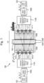
- FIG. 1 is a block diagram of an example acoustic MIMO communication system 100.
- the diagram shows the top level blocks that support the transmission of data from a data source 102 on the left-hand side, via an acoustic MIMO data link 101, to a data sink 104 on the right-hand side.
- the example system is intrinsically symmetrical (although in practice there may be lateral offsetting of some components) and could alternatively be used to transmit data from right to left, with the roles of the source 102 and sink 104 being reversed.
- the example embodiment is intended to provide high speed digital communications through a thin, e.g. 10mm thick, wall/barrier 103 of ballistic grade aluminium over the frequency range 80MHz to 120MHz.
- the embodiment can be capable of supporting data transfer rates of greater than 300Mbps.
- data from the data source 102 is accumulated in a first MIMO modem 108A, which constructs frames of data consisting of a serial sequence of many symbols partitioned into 4 separate data streams.
- Each of these data streams can be configured to be independent, thus allowing the same frequency bandwidth to support a much larger data transmission rate.
- the symbols of each data stream are turned into electrical time-domain waveforms which are made up of an array of frequency tones occupying the frequency bandwidth ⁇ f of the system.
- This frequency bandwidth will be fundamentally limited to that supportable by transducers in a pair of MIMO transceiver devices/chips 106A, 106B included in the acoustic MIMO data link 101. In the example embodiment 100 this available frequency bandwidth is 40MHz.
- embodiments of the communication system can be modified to work with any suitable MIMO protocol.
- the output impedance of the four outputs of the first MIMO modem 108A will, in general, not be electrically matched to the input impedance of the array of transducers in the acoustic MIMO data link 101.
- Electrical impedance matching is achieved using a first electrical impedance matching circuits block 112A associated with the first modem 108A. This block contains 4 nominally identical electrical impedance matching circuits, one for each transducer of a first MIMO transceiver device/chip 106A.
- the acoustic MIMO data link 101 in the example embodiment comprises the first MIMO transceiver device/chip 106A and a second MIMO transceiver device/chip 106B.
- Each of the MIMO devices/chips 106A, 106B comprises a body 109A, 109B, each of which is formed of a block of single crystal sapphire in the example embodiment.
- the body/block of each MIMO device/chip has an array of 4 identical transducers (labelled 107A - 107D for device 106A and 107'A - 107'D for device 106B).
- the transducers may be mounted onto the body by being bonded onto the crystalline C-axis face using a vacuum cold weld bond of gold, but other metals and mounting/bonding methods are possible. It will also be appreciated that the positioning of the transducers can vary.
- the size of the blocks is not a critical parameter, nor do they have to be rectangular and other shapes are possible.
- the transducer mounting surface of the block does not need to be parallel to the surface of the block that is, in use, mounted on the barrier 103. It is, however, beneficial to reduce the size of the transducer mounting surface so that multipath reflections off the side walls of the chips contribute more strongly to the overall multipath signal environment.
- each sapphire block is 8mm, and its transducer mounting surface is 11mm long by 5.8mm wide. These dimensions conveniently support the parallel processing of 28 device blanks as illustrated by the photograph image of Figure 5 (see below), which shows a 7 by 4 array of partly processed devices mounted in a polishing jig used to thin the transducers to their final thickness.
- Sapphire is a particularly suitable material for the MIMO device chips 106A, 106B because the speed of sound along the C-axis of sapphire is unusually high at ⁇ 11,000 m/s for longitudinal waves. This for the same acoustic transit loss that will reduce the reverberation time for multipath signals within each MIMO device chip and so reduce the required Guard Interval for any MIMO-COFD coding scheme.
- the high velocity also means the length of the chip can be made shorter than with an alternative material to achieve the same level of acoustic overlap over the Rx transducer array; note the acoustic wavelength in sapphire at a given frequency is much longer than other materials due to its the higher speed of sound.
- acoustic diffraction for a given electrode size is higher.
- the benefit of reducing the Guard period is that shorter Symbol duration's ⁇ can be supported, which allows the same data rate to be supported with fewer frequency tones. This in turn allows the frequency band-pass filters to be made wider, and also requires smaller point number IFFT and FFT operations, albeit generated at a faster rate. This is very beneficial to the overall computation complexity because the number of numerical operations required in the digital electronics to calculate an IFFT or FFT scales at the rate of O ( N log 2 N ) operations (technically, O only denotes an upper bound) where N is the number of points in the IFFT or FFT.
- the acoustic attenuation of sapphire is very low at a frequency of ⁇ 100MHz.
- the body 109A, 109B of each device 106A, 106B can act as a reverberation chamber. This, coupled with the highly diffracting beams launched by each of the separate transducers, supports the creation of a complex set of multipath signals.
- Sapphire is also mechanically extremely rugged. Other (single or combined) materials in place of Sapphire could be used; for instance un-doped YAG, or, for example, fused silica which has the benefit of being a very cheap material compared to single crystal sapphire. Other dielectric materials are also possible, provided they are low acoustic loss materials.
- the electrical waveform emerging from each of the four electrical impedance matching circuit block 112A are applied the associated acoustic transducers 107A - 107D of the first MIMO device/chip 106A.
- the acoustic signals produced by these transducers are then transmitted across the barrier 103 to the second MIMO data device/chip 106B.
- the acoustic signals are reconverted into an electrical signal of considerably greater complexity than the original Symbol waveforms that were transmitted on the input side acoustic MIMO data link 101.
- These received signals are then impedance matched to the input impedance of a second MIMO modem 108B using a second electrical impedance matching circuits block 112B.
- This electrical impedance matching block will in a symmetrical physical geometry be nominally identical to the first electrical impedance matching block 112A.
- the second MIMO modem 108B then decodes the received signal and transfers the data to the data sink 104.
- the acoustic MIMO data link 101 in the example embodiment further comprises layers 120A, 120B that, in use, bond/mount the first 106A and second 106B MIMO devices/chips onto opposite faces of the barrier 103.
- the two bonding layers are nominally identical and in the example embodiment comprise the two part epoxy resin MasterBond Inc EP30 doped with 13 ⁇ m diameter polymer micro-pearl spheres at a concentration of ⁇ 2% by dry volume (although other concentrations could be used) to the epoxy resin mix.
- the diameter of the micro-pearl spacers may need to be adjusted to, probably, a larger diameter to accommodate compression of the spheres under adhesive curing load pressures, and also the bonding surfaces are not perfectly smooth.
- Suitable polymer spheres are supplied by Sekisui Chemical Co Ltd of Japan, product number SP-213.
- the final target thickness for the bond line is 12.35 ⁇ m in the example embodiment.
- Bond adhesion to the barrier is enhanced by lapping the mating bonding surfaces to a surface finish courser than 0.2 ⁇ m CLA.
- an encapsulated MIMO device/chip may be clamped to a solid barrier immersed in a fluid, with the fluid medium between the encapsulated MIMO device and the barrier functioning as an acoustic coupling layer that is acoustically exactly like, for example, a bond layer.
- Acoustic coupling between the first 106A and the second 106B MIMO devices and the barrier 103 can alternatively be achieved by other types of layers, e.g. acoustic coupling gel, a fluid, or a solder joint.
- a solder joint would require very careful selection design because most dielectric materials have a considerably smaller coefficient of thermal expansion to that of a barrier.
- Spacer particles such as nickel spheres, would be needed to ensure the solder joint was thick enough to be sufficiently resilient to accommodate the CTE mismatch between the soldering temperature and actual operational temperatures, which would be much lower. Spacers may be added to the bond layers 120A, 120B to ensure a repeatable bond layer thickness, and thus reproducible reflectivity.
- the reflectivity of each of the bond layers varies periodically between 18% and 98%, as a function of bond thickness. Transmission peaks occur at ⁇ 8.2 ⁇ m intervals with transmission peaks at bond thicknesses calculated to occur at 4.15 ⁇ m, 12.35 ⁇ m, etc, for sound incident at normal incidence. It will be appreciated that the figures for other embodiments will differ.
- the widest frequency response for high reflection at the bond interface occurs with a 4.15 ⁇ m thick bond line
- a better choice for practical implementation is a 12.35 ⁇ m thick bond layer 120A, 120B.
- the thicker bond layer will be more resistant to possible bond delamination caused by thermal cycling. Even so the reflectivity of the bond layer will exceed 94.5% over the frequency range of 80MHz to 120MHz.
- the acoustic signals emitted by each transducer spread rapidly due to acoustic diffraction and so deep transmission notches would be at least partly smeared out by multipath processes.
- EP30 adhesives instead of EP30 could be used, but the optimal thickness of the bonds would need to be fine-tuned to match the acoustic velocity of the adhesive used (the calculated velocity of longitudinal acoustic waves in EP30 adhesive is 1645m/s derived from density and Young's modulus data).
- the highly reflective acoustic bond layers 120A, 120B of the example embodiment support the creation of a reverberation chamber within each of the transceiver device chips 106A, 106B. This results in a complex set of multipath signals. To a lesser degree, further multipath may be created within the acoustically attenuating barrier 120 itself. The further multipath complexity is created by acoustic mode conversion processes that occur when the sound waves reflect off oblique surfaces in the MIMO devices 106. The end result is an acoustic data link with a rich and complex multipath character that includes a huge array of different time of flight signals. This naturally supports high data rate MIMO communications (provided the transducer electrodes are more than 0.5 acoustic wavelengths apart in each array).
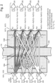
- every transmit transducer (107A - 107B in the example embodiment) broadcasts acoustic signals which are later received by all of the receive (107'A - 107'D) transducers. This occurs through a combination of rapid angular spreading of the acoustic signal emitted by each of the launch/transmit transducers due to diffraction, and also multipath reflections within each MIMO device/chip 106A, 106B, and to a lesser degree in the barrier 103.
- the various arrows shown in Figure 2 connect every launch transducer to every receive transducer. These arrows represent the signal channel coefficients H i j of the data link, and the signal channel coefficients H ij represents the multipath signal mapping for each launch transducer j to each receiver transducer i.
- H ij If the H ij signal channel coefficients are known, or can be deduced using known pilot tones, then the original set of launched Symbols can be recovered. This can be achieved, for example, by multiplying the received signals S Rj by the inverse matrix H -1 ij of the signal channel coefficients matrix H i j .
- a key requirement therefore is that the determinant of the matrix H i j is not zero in value. This in turn means that the matrix H ij must be mathematically invertible, that is, non degenerate: S Ti ⁇ H ij ⁇ 1 ⁇ S Rj + H ij ⁇ 1 ⁇ N j
- the set of N dimensional Vectors formed by each of the rows, or alternatively columns are most preferably substantially independent.
- the original Symbols can, however, only be recovered provided the signal to noise performance of the data link is good enough such that the Forward Error Correction algorithm applied to the transmitted Symbols can correct sub-symbol errors.
- the signal to noise requirement for a MIMO system is therefore more demanding than a conventional SISO system employing COFDM, because of the MIMO systems greater complexity.
- the acoustical thickness of the piezoelectric layer is 0.541 ⁇ while that of the buffer layer is 1/18.65 ⁇ , where ⁇ is an acoustical wavelength in the material of the respective layers. These wavelengths and impedances are in terms of acoustical signals of 100MHz frequency.
- a metallic bonding layer Between each of the above substrates of the structure can be a metallic bonding layer. These include a bonding layer Cr-Au 918 between the sapphire substrate 915 and the fused silica buffer layer 917, and a second bonding layer Cr-Au (70 nm Au) 920 between the buffer layer 917 and the piezoelectric platelet 916. The second bonding layer also provides the electrical ground plane electrode for the piezoelectric layer 916.
- each bond layer On top of each bond layer is deposited respectively a Cr-Au ( ⁇ 300 nm Au) thickening layer 919, and then later a second Cr-Au ( ⁇ 300 nm Au) thickening layer 921.
- Cr-Au ⁇ 300 nm Au
- a second Cr-Au ⁇ 300 nm Au
- These layers protect each of the thin bond metallisation layers 924 during the lapping and thinning processes of first the buffer layer 917 and then the piezoelectric platelet 916. This protection of the original bonding layers is particularly important at the boundary of each bonded structure where abrasive particles can gather during the lapping and polishing processes; such particles could cause an open circuit connection to the ground plane electrode below the bonded transducer.
- the structure is completed by a 'live' electrode Au ( ⁇ 100 nm) 922 of nominal thickness 100nm and an aperture of 1 ⁇ 0.2mm 2 .
- the 'live' wire (or tape) bond 925, and the two 'ground' wire or tape bonds 926 shown in Figure 9 connect to the 'live' electrode 922, and ground plane metallisation layers 924 to the flexi-circuit electrical fan out 930 shown in Figure 5 .
- Adjacent transducer channels are electrically isolated on the MIMO devices 106A, 106B by electrical isolation tracks. Their purpose is to suppress inter-channel Tx cross talk created by the sheet resistance of the thin ground plane metallisation layers on the MIMO devices. Inter-channel cross talk is undesirable because it interferes with the spatial orthogonality of the separate data streams transmitted by each transducer channel.
- the dog leg bends in two of the three isolation tracks shown in Figure 5 are to ensure that the area of the ground planes available to connect to the four channels of the flexi-circuit electrical fan out is similar for each electrode.
- each transducer 107, 107' The three substrates making up each transducer 107, 107' are each bonded together in two separate vacuum cold weld bond processes. This vacuum cold weld process is described below.
- the transducers 107A - 107D of the example embodiment are spaced at intervals of 1.6mm on the MIMO device 106A.
- the live electrode 922 on each identical transducer consists of a 0.2mm ⁇ 1mm rectangle, with the shortest dimension parallel to the axis of the transducer array. This ensures that the highest far field diffraction occurs along the axis of the transducer array; this ensures a particularly rich multipath signal channel along this axis.
- the length of the long axis of the transducer is chosen mainly for convenience, in part to reduce the length of the individual transducer platelets needed to accommodate the active electrode, and thus reduce the total loading force required during transducer bonding. Setting the overall area of the transducer live electrode 922 to 0.2 mm 2 does however lead to relative high input impedance for the tuned transducer, as explained below.
- the width of the transducer electrodes on each transducer 107, 107' is, in wavelength terms, small (e.g. less than ⁇ /2.2). Therefore, rapid diffraction occurs in the plane perpendicular to the long axis of the transducer ⁇ live' electrode 922. In sapphire the acoustic wavelength varies from ⁇ 137.5 ⁇ m at 80MHz to ⁇ 91.7 ⁇ m at 120MHz.
- Embodiments of the fabrication geometry disclosed herein lend themselves to parallel processing of a block of device chips as illustrated in Figure 5 , which reduces the processing cost of the acoustic MIMO device blanks.
- Figure 3 illustrates the far field acoustic diffraction envelopes 355, etc, that each emanate from an associated electrode channel in each transducer 107, 107', etc., of the example embodiment.
- the near field Rayleigh distance representing the boundary between near field diffraction and far field diffraction is shown in Figure 3 .
- the transition from the near field where the acoustic beam remains approximately collimated, to the far field where the beam diverges in accordance to the I ( ⁇ ) equation above, occurs at ⁇ 0.44mm from each transducer at 120MHz, and at an even shorter distance at 80MHz.
- the full angular width of the far field central diffraction lobe to the zero intensity points is equal to the angle 2 ⁇ 1 shown in Figure 3 .
- the full angular width 2 ⁇ 1 varies from 86.8° at 80MHz to 54° at 120MHz within the sapphire crystal blank.
- Acoustic refraction at the bond interface 120A reduces the corresponding angular width 2 ⁇ 1 of the central diffraction lobe to 46° at 80MHz, and 30° at 120MHz within the barrier.
- a second refraction process occurs at the second bond interface (6) again increases the full angle angular spread of the central lobe to 86.8° at 80MHz to 54° at 120MHz within the second sapphire crystal blank, as illustrated in Figure 4 .
- the central diffraction lobe launched by the electrode (channel 1) begins to overlap the bore sight axis of the rightmost electrode (channel 4) at a range of ⁇ 11,3mm at 120MHz. At all other operating frequencies of embodiment 1 this overlap range is closer.
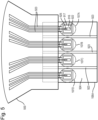
- Figure 7 shows a prototype device chip with four electrode channels on a fused silica block. Two chips are then bonded to a barrier, one on each side of the barrier to support high data rate ultrasonic communications across the barrier.
- the separation between adjacent electrodes 922 is 1.6mm, the height of the device blank is 8mm.
- Components of the acoustic MIMO data link 101 can be fitted to an (at least partially) existing MIMO communication system, e.g. connected to each side of a barrier positioned between MIMO modems.
- the Tx and Rx transducers to operate over as wide an overlapping frequency bandwidth as possible.
- the centre frequency of the transducers desirably is made as low as possible to reduce the impact of acoustic attenuation within the barrier.
- bulk acoustic attenuation within a homogenous and grain structure free material exhibits a quadratic dependence on frequency when expressed in units of dB/cm.
- a lower power law of increase with frequency albeit from a much higher baseline are quite common. This is because of the impact of extrinsic acoustic attenuation losses such as the presence of impurities or grain boundaries.
- the lowest recommended centre frequency f c for the acoustic data link may be subject to the requirement that the transducer should operate over less than an octave of frequency bandwidth, i.e. ⁇ f / f c >0.66 fc.
- COFDM complex communications protocols
- Such protocols are intended for use in a signal transmission environment characterised by high levels of signal multipath which are caused by reflections off a large number of surfaces.
- COFDM requires a very linear signal response that is as free as possible from spurious signals created by multiple order non-linear mixing processes. Such mixing processes can occur either in the electronics of the system, or can alternatively be generated by acoustic mixing processes within the propagation medium at very high acoustic power density levels.
- the design work discussed below refers to 36°Y cut lithium niobate transducers which were designed to operate at a centre frequency of 100MHz.
- the choice of this particular piezoelectric material and the 36°Y cut in particular was determined by the requirement to transmit longitudinal polarised acoustic waves. These waves exhibit much lower acoustic attenuation, particularly in metallic barriers, than a shear polarised wave.
- the data transfer rate that is supportable by an acoustic MIMO device data link is dependent on the available frequency bandwidth of the link, and signal communications protocol used.
- Most COTS MIMO communications hardware are designed to operate over frequency bandwidths that are multiples of 20MHz or 10MHz. Bandwidths typically used are 20MHz, 40MHz, 80MHz and 160MHz. For most applications an 80MHz or 160MHz bandwidth is not practical due to the particularly high centre frequencies, ⁇ 160MHz or ⁇ 320MHz needed to support these bandwidths. This is a consequence of the typical ⁇ 50% fractional bandwidth ⁇ f / f c performance limit of 36°Y cut lithium niobate piezoelectric transducers. Such high centre frequencies suffer from extremely high frequency dependent attenuation in most barrier materials.
- a centre frequency of 100 MHz was chosen for the example embodiment representing a MIMO data link intended to work through a 10mm thick aluminium barrier.
- the transducer bond layer is acoustically highly reflecting unless the adhesive bond layer is made extremely thin. Consequently, the mechanically vibrating transducer structure will have a very high mechanical Q unless the adhesive bond layer is less than 1/165 ⁇ thick at the centre frequency of 100MHz. Particulate contamination outside a cleanroom processing environment would realistically preclude the achievement of such a thin bond layer. It is in part for this reason that the transducer must be bonded to a substrate in a cleanroom environment.
- a good bonding solution is for example a vacuum cold weld metallic bond of controlled thickness. This substrate then in turn is mounted on the barrier.
- each transceiver device can be modified by adding a controlled absorbing layer on the outer exposed surfaces of the device.
- a controlled absorbing layer could be applied over part of the transducer face's metallisation layers to speed the rate of decay of multipath signals within the transceiver device.
- Such absorbing layers can be achieved by adding a layer of epoxy of controlled thickness that is doped with tungsten particles.
- Block processing techniques can be employed to substantially reduce the unit price of the acoustic data links.
- Arrays of device chips on a single block are all processed in parallel.
- Block processing techniques can be employed successfully as illustrated in Figure 6 .
- the polishing jig in this specific case was used to simultaneously thin all of the device transducers, a total of 112 transducer platelets for 28 device blanks, to a common thickness.
- Figure 7 shows an individual device chip after dicing up of the processed block of devices, including the detail of the bonded transducers, the electrical isolation tracks between each adjacent transducer, and their sputtered electrodes.
- the substrate used in these device chips was fused silica, while the bonded transducers were made from 36°Y cut lithium niobate.
- No intermediate buffer layer of the type indicated in Figure 9 was used on these device chips because the main substrate was fused silica and not sapphire for reasons of cost. If a substrate with higher acoustic impedance than the transducer material was used, then it could be very beneficial for the frequency bandwidth to use an intermediate buffer layer between the piezoelectric layer and the main substrate.
- Processing of the device chips can begin by taking a rectangular block of optically polished material with a surface finish of better than 10-5 scratch dig.
- the block is first cleaned to remove all surface contamination particularly on the transducer mounting surface.
- a rectangular array of transducer platelets are then bonded onto it using a vacuum cold weld bonding process in a class 10 cleanroom (equivalent to ISO 4 standard).
- Inspection of the microscope photograph of Figure 7 shows that the resulting relative alignment and spacing of the bonded transducers is very accurate, in this case to better than +/- 0.1 mm.
- the length and width of the each bonded transducer platelet in the photograph is 5.68mm ⁇ 1.28mm.
- the pitch between adjacent transducers was 1.6mm. This linear pitch corresponds to an acoustic spacing of ⁇ 21.4 acoustic wavelengths at 80MHz within the fused silica main substrate.
- the vacuum cold weld process can involve evaporating a thin keying layer of evaporated chrome of nominal thickness 10nm, followed immediately by a thicker controlled thickness of 35nm of gold onto the two surfaces to be bonded together.
- Each of the surfaces to be bonded must be highly polished to ⁇ 10-5 scratch dig finish, flat to better than ⁇ /20 per cm at 633nm. All surfaces of the substrates must be very clean, and the bonding surfaces free of particulate contamination.
- the bonding process is performed in a vacuum chamber pumped down to a residual pressure of better than 3 ⁇ 10 -7 or better mBar. Sputtered or evaporated chrome, unlike sputtered gold, keys strongly to dielectrics such as sapphire, YAG, or fused silica.
- the two freshly metallised surfaces are then brought carefully together while still under a vacuum of 3 ⁇ 10 -7 or better mBar, then when in contact subjected to a sustained high pressure load.
- Neither the buffer layer, nor the subsequent piezoelectric platelet is bonded at their final design thicknesses. Instead, relatively thick platelets typically ⁇ 1mm thick are bonded.
- the bonded platelets are then lapped and optically polished to their final design thickness. Electrical isolation of the individual ground planes for each bonded transducer platelet are created by either an Ion Beam Milling etching process, or alternatively but less good, a wet etching process. Electrodes of a Chrome flash followed by a 100nm thick gold layer are then deposited onto each of the bonded transducers through a photolithography mask. The final task is to dice the completed block into individual device chips using for example a wafer saw.
- the mounting of the MIMO device may not be perfectly symmetrical as shown in Figure 4 .
- perfect symmetry will never be achieved since this would imply placement accuracies of better than 10 ⁇ m which is not realistic.
Landscapes
- Engineering & Computer Science (AREA)
- Physics & Mathematics (AREA)
- Signal Processing (AREA)
- Acoustics & Sound (AREA)
- Computer Networks & Wireless Communication (AREA)
- Mechanical Engineering (AREA)
- Multimedia (AREA)
- General Physics & Mathematics (AREA)
- Radar, Positioning & Navigation (AREA)
- Remote Sensing (AREA)
- Health & Medical Sciences (AREA)
- Life Sciences & Earth Sciences (AREA)
- Chemical & Material Sciences (AREA)
- Analytical Chemistry (AREA)
- Biochemistry (AREA)
- General Health & Medical Sciences (AREA)
- Immunology (AREA)
- Pathology (AREA)
- Transducers For Ultrasonic Waves (AREA)
- Surface Acoustic Wave Elements And Circuit Networks Thereof (AREA)
- Piezo-Electric Transducers For Audible Bands (AREA)
- Radio Transmission System (AREA)
- Transceivers (AREA)
Claims (12)
- Liaison de données (101) pour un système de communication MIMO (100) comprenant :un premier dispositif émetteur-récepteur (106A) comprenant un premier corps (109A) ayant une surface de montage de transducteur près ou au niveau de laquelle est montée une pluralité de premiers transducteurs (107A - 107D) conçus pour, en cours d'utilisation, recevoir et convertir une pluralité de formes d'ondes électriques en une pluralité respective de signaux acoustiques ;une première couche de collage (120A) conçue pour, en cours d'utilisation, coller une surface de montage de barrière du premier corps du premier dispositif émetteur-récepteur opposée à sa surface de montage de transducteur à une barrière (103) à travers laquelle la pluralité de signaux acoustiques délivrés par le premier dispositif émetteur-récepteur est transmise ;un second dispositif émetteur-récepteur (106B) comprenant un second corps (109B) ayant une surface de montage de transducteur près ou au niveau de laquelle est montée une pluralité de seconds transducteurs (107'A - 107'D) conçus pour, en cours d'utilisation, recevoir et convertir la pluralité de signaux acoustiques transmis à travers la barrière en une pluralité respective de formes d'ondes électriques, etune seconde couche de collage (120B) conçue pour, en cours d'utilisation, coller une surface de montage de barrière du second corps du second dispositif émetteur-récepteur opposée à la surface de montage de transducteur à la barrière ;caractérisée en ce que la première couche de collage (120A) et la seconde couche de collage (120B) sont hautement réfléchissantes etsont agencées de manière à réfléchir la pluralité de signaux acoustiques délivrés par le premier dispositif émetteur-récepteur de telle sorte que, en cours d'utilisation, le premier corps (109A) du premier dispositif émetteur-récepteur (106A) et le second corps (109B) du second dispositif émetteur-récepteur (106B) fonctionnent comme des chambres de réverbération pour les signaux acoustiques.
- Liaison de données selon la revendication 1, dans laquelle le premier corps (109A) du premier dispositif émetteur-récepteur (106A) et le second corps (109B) du second dispositif émetteur-récepteur (106B) comprennent chacun du saphir ou du saphir monocristallin.
- Liaison de données selon l'une quelconque revendication précédente, dans laquelle une épaisseur de la première couche de collage (120A) et/ou de la seconde couche de collage (120B) est comprise dans une plage d'environ 4,0 µm à environ 4,30 µm, ou dans une plage d'environ 12,2 µm à environ 12,5 µm, ou est d'environ 4,15 µm, ou est d'environ 12,35 µm.
- Liaison de données selon l'une quelconque revendication précédente, dans laquelle la première couche de collage (120A) et/ou la seconde couche de collage (120B) comprennent une couche à faible perte acoustique.
- Liaison de données selon l'une quelconque revendication précédente, dans laquelle la première couche de collage (120A) et/ou la seconde couche de collage (120B) comprennent un matériau en résine dopé avec un matériau d'espacement, par ex. des micro-perles/sphères de polymère.
- Liaison de données selon l'une quelconque des revendications 1 à 4, dans laquelle la première couche de collage (120A) et/ou la seconde couche de collage (120A) comprennent un gel de couplage acoustique, un fluide ou un joint de soudure.
- Liaison de données selon l'une quelconque revendication précédente, dans laquelle le premier corps (109A) du premier dispositif émetteur-récepteur (106A) et le second corps (109B) du second dispositif émetteur-récepteur (106B) comprennent chacun un bloc ou sont de forme cubique.
- Liaison de données selon la revendication 7,
dans laquelle au moins une surface de paroi s'étend entre la surface de montage de transducteur et la surface de montage de barrière du premier corps (109A) du premier dispositif émetteur-récepteur (106A), et au moins une surface de paroi s'étend entre le second corps (109B) du second dispositif émetteur-récepteur (106B). - Liaison de données selon la revendication 8, dans laquelle au moins une dimension de ladite surface de montage de transducteur est relativement plus petite qu'au moins une dimension correspondante de ladite surface de paroi.
- Liaison de données selon l'une quelconque revendication précédente, dans laquelle une électrode active (922) de chacun de la pluralité de premiers transducteurs (107A - 107D) est rectangulaire, elliptique ou en forme de diamant, une dimension la plus courte de la forme étant parallèle à un axe principal de la pluralité de premiers transducteurs.
- Liaison de données selon l'une quelconque revendication précédente, dans laquelle les positions de la pluralité de premiers transducteurs (107A- 107D) sont non périodiques et non symétriques par rapport aux positions de la pluralité de seconds transducteurs (107'A- 107'D).
- Système de communication MIMO (100) comprenant une liaison de données MIMO (101) selon l'une quelconque revendication précédente, le système comprenant en outre :un premier modem MIMO (108A) conçu pour, en cours d'utilisation, recevoir et convertir un signal d'entrée afin de délivrer la pluralité de formes d'ondes électriques vers le premier dispositif émetteur-récepteur (106A), etun second modem MIMO (108B) conçu pour, en cours d'utilisation, recevoir et convertir la pluralité de formes d'ondes électriques délivrées par le second dispositif émetteur-récepteur (106B) afin de produire un signal de sortie.
Applications Claiming Priority (2)
| Application Number | Priority Date | Filing Date | Title |
|---|---|---|---|
| GB1620851.4A GB2557345B (en) | 2016-12-08 | 2016-12-08 | MIMO communication system and data link |
| PCT/GB2017/053554 WO2018104702A1 (fr) | 2016-12-08 | 2017-11-27 | Système de communication mimo et liaison de données |
Publications (3)
| Publication Number | Publication Date |
|---|---|
| EP3552405A1 EP3552405A1 (fr) | 2019-10-16 |
| EP3552405B1 true EP3552405B1 (fr) | 2024-09-04 |
| EP3552405B8 EP3552405B8 (fr) | 2024-10-16 |
Family
ID=58222103
Family Applications (6)
| Application Number | Title | Priority Date | Filing Date |
|---|---|---|---|
| EP17275112.5A Ceased EP3334181A1 (fr) | 2016-12-08 | 2017-07-19 | Transducteur |
| EP17275128.1A Ceased EP3432595A1 (fr) | 2016-12-08 | 2017-08-25 | Transducteur électroacoustique |
| EP17807918.2A Active EP3552405B8 (fr) | 2016-12-08 | 2017-11-27 | Système de communication mimo et liaison de données |
| EP17807919.0A Active EP3552406B1 (fr) | 2016-12-08 | 2017-11-27 | Transducteur |
| EP18737403.8A Active EP3656134B1 (fr) | 2016-12-08 | 2018-07-10 | Réseau de transducteurs électroacoustiques |
| EP18739917.5A Active EP3656135B1 (fr) | 2016-12-08 | 2018-07-10 | Transducteur électroacoustique |
Family Applications Before (2)
| Application Number | Title | Priority Date | Filing Date |
|---|---|---|---|
| EP17275112.5A Ceased EP3334181A1 (fr) | 2016-12-08 | 2017-07-19 | Transducteur |
| EP17275128.1A Ceased EP3432595A1 (fr) | 2016-12-08 | 2017-08-25 | Transducteur électroacoustique |
Family Applications After (3)
| Application Number | Title | Priority Date | Filing Date |
|---|---|---|---|
| EP17807919.0A Active EP3552406B1 (fr) | 2016-12-08 | 2017-11-27 | Transducteur |
| EP18737403.8A Active EP3656134B1 (fr) | 2016-12-08 | 2018-07-10 | Réseau de transducteurs électroacoustiques |
| EP18739917.5A Active EP3656135B1 (fr) | 2016-12-08 | 2018-07-10 | Transducteur électroacoustique |
Country Status (5)
| Country | Link |
|---|---|
| US (4) | US11647339B2 (fr) |
| EP (6) | EP3334181A1 (fr) |
| AU (2) | AU2017371617B2 (fr) |
| GB (2) | GB2557345B (fr) |
| WO (4) | WO2018104702A1 (fr) |
Families Citing this family (17)
| Publication number | Priority date | Publication date | Assignee | Title |
|---|---|---|---|---|
| GB2557345B (en) | 2016-12-08 | 2021-10-13 | Bae Systems Plc | MIMO communication system and data link |
| CN109412698B (zh) * | 2018-10-10 | 2022-01-25 | 南京邮电大学 | 一种基于衍射效应的多输入多输出光通信系统及通信方法 |
| GB2580776B (en) | 2018-12-19 | 2022-12-28 | Bae Systems Plc | Munitions and projectiles |
| EP3899415B1 (fr) * | 2018-12-19 | 2024-08-28 | BAE SYSTEMS plc | Appareil et procédé appropriés pour une utilisation avec une munition |
| AU2020309594B2 (en) * | 2019-07-10 | 2025-12-04 | Ulink Labs, Inc. | Systems, devices, and methods for establishing a wireless link |
| US12034434B2 (en) | 2019-08-23 | 2024-07-09 | Northeastern University | High quality factor integrated acoustic resonant metamaterials with large frequency tuning range for reconfigurable radio-frequency front-ends |
| CN110477951B (zh) * | 2019-08-30 | 2020-08-25 | 浙江大学 | 基于宽频带声学超材料的超快复合平面波成像方法 |
| EP3822963B1 (fr) * | 2019-11-15 | 2024-01-03 | Heraeus Amloy Technologies GmbH | Composant de transmission des ondes acoustiques ainsi que procédé de fabrication d'un composant de transmission des ondes acoustiques |
| CN112152728B (zh) * | 2020-09-18 | 2021-07-27 | 西北农林科技大学 | 一种面向行为感知的便捷超声多路收发硬件系统 |
| US11504093B2 (en) * | 2021-01-22 | 2022-11-22 | Exo Imaging, Inc. | Equalization for matrix based line imagers for ultrasound imaging systems |
| US12053330B2 (en) | 2021-06-23 | 2024-08-06 | Exo Imaging, Inc. | Systems and methods for testing MEMS arrays and associated ASICs |
| AU2022301200A1 (en) | 2021-06-29 | 2024-01-04 | Ulink Labs, Inc. | Systems, devices, and methods for establishing a wireless link in a heterogeneous medium |
| KR102620679B1 (ko) * | 2021-07-14 | 2024-01-04 | 인천대학교 산학협력단 | 기성품 차량 레이더, 모션센서 레이더의 방사파 성능을 향상시키는 메타표면 커버, 메타표면 커버를 사용한 레이더 안테나 및 레이더 안테나 구조체 |
| CN114203146B (zh) * | 2021-12-13 | 2025-03-21 | 哈尔滨工程大学 | 一种可实现声波非对称传播的超表面模型 |
| US11863239B2 (en) * | 2022-02-11 | 2024-01-02 | L3Harris Technologies, Inc. | Cellular automaton for use in long-range acoustic networks |
| CN115623853B (zh) * | 2022-12-20 | 2023-05-12 | 中南大学 | 一种柔性取向多孔阵列式压电陶瓷发电器件及其制备和应用 |
| US20250049384A1 (en) * | 2023-08-08 | 2025-02-13 | The Regent Of The University Of Michigan | Photo acoustic qualitative ultrasound bone densitometer |
Family Cites Families (57)
| Publication number | Priority date | Publication date | Assignee | Title |
|---|---|---|---|---|
| US2906993A (en) * | 1946-05-22 | 1959-09-29 | Raymond L Steinberger | Transducer for underwater sound |
| US3337843A (en) * | 1965-12-20 | 1967-08-22 | Paul M Kendig | Underwater transducer array for deep submergence |
| US3891871A (en) | 1974-05-24 | 1975-06-24 | Us Navy | Pressure release hemispherical piezoelectric type transducer |
| US3946599A (en) | 1974-11-08 | 1976-03-30 | Jacob Patt | Liquid applicator for ultra-sonic transducer |
| US4033178A (en) * | 1976-04-23 | 1977-07-05 | The Babcock & Wilcox Company | Fluid coupled test probe |
| US4246791A (en) * | 1978-03-27 | 1981-01-27 | New York Institute Of Technology | Ultrasonic imaging apparatus |
| US4482834A (en) * | 1979-06-28 | 1984-11-13 | Hewlett-Packard Company | Acoustic imaging transducer |
| EP0031614B2 (fr) | 1979-12-17 | 1990-07-18 | North American Philips Corporation | Réseau courbe de transducteurs ultrasoniques |
| US4545385A (en) * | 1982-03-23 | 1985-10-08 | Siemens Aktiengesellschaft | Ultrasound examination device for scanning body parts |
| US4565096A (en) * | 1983-12-09 | 1986-01-21 | Rosemount Inc. | Pressure transducer |
| DE3501808A1 (de) | 1985-01-21 | 1986-07-24 | Siemens AG, 1000 Berlin und 8000 München | Ultraschallwandler |
| US5052393A (en) | 1988-09-16 | 1991-10-01 | Hewlett-Packard Company | Ultrasound system with improved coupling fluid |
| US4982385A (en) * | 1989-11-17 | 1991-01-01 | Westinghouse Electric Corp. | Acoustic decoupler for a sonar array |
| GB9225898D0 (en) * | 1992-12-11 | 1993-02-03 | Univ Strathclyde | Ultrasonic transducer |
| US5494038A (en) | 1995-04-25 | 1996-02-27 | Abbott Laboratories | Apparatus for ultrasound testing |
| US5770801A (en) * | 1995-04-25 | 1998-06-23 | Abbott Laboratories | Ultrasound transmissive pad |
| US5648941A (en) * | 1995-09-29 | 1997-07-15 | Hewlett-Packard Company | Transducer backing material |
| JP2000131298A (ja) * | 1998-10-23 | 2000-05-12 | Matsushita Electric Ind Co Ltd | 超音波探触子 |
| US6155982A (en) | 1999-04-09 | 2000-12-05 | Hunt; Thomas J | Multiple sub-array transducer for improved data acquisition in ultrasonic imaging systems |
| FR2800229B1 (fr) | 1999-10-22 | 2002-04-05 | Thomson Marconi Sonar Sas | Transducteur acoustique sous-marin a large bande |
| GB0026021D0 (en) | 2000-10-24 | 2000-12-13 | Univ Cambridge Tech | Sensing apparatus and method |
| US6685647B2 (en) * | 2001-06-28 | 2004-02-03 | Koninklijke Philips Electronics N.V. | Acoustic imaging systems adaptable for use with low drive voltages |
| US6758094B2 (en) * | 2001-07-31 | 2004-07-06 | Koninklijke Philips Electronics, N.V. | Ultrasonic transducer wafer having variable acoustic impedance |
| US6690620B1 (en) | 2002-09-12 | 2004-02-10 | The United States Of America As Represented By The Secretary Of The Navy | Sonar transducer with tuning plate and tuning fluid |
| US6895825B1 (en) * | 2004-01-29 | 2005-05-24 | The Boeing Company | Ultrasonic transducer assembly for monitoring a fluid flowing through a duct |
| JP4513596B2 (ja) * | 2004-08-25 | 2010-07-28 | 株式会社デンソー | 超音波センサ |
| US8063473B1 (en) * | 2004-11-29 | 2011-11-22 | The United States Of America As Represented By The Secretary Of The Navy | Nanophotonic transceiver |
| US9049520B2 (en) | 2006-01-20 | 2015-06-02 | Akrion Systems Llc | Composite transducer apparatus and system for processing a substrate and method of constructing the same |
| US8650958B2 (en) * | 2006-02-02 | 2014-02-18 | The Boeing Company | Thin-film ultrasonic probe having a flexible membrane |
| US7719170B1 (en) * | 2007-01-11 | 2010-05-18 | University Of Southern California | Self-focusing acoustic transducer with fresnel lens |
| US7694570B1 (en) * | 2007-03-30 | 2010-04-13 | Cosense, Inc | Non-invasive dry coupled disposable/reusable ultrasonic sensor |
| NO330292B1 (no) | 2007-09-12 | 2011-03-21 | Det Norske Veritas As | Akustiske tykkelsesmalinger ved bruk av gass som et koblingsmedium |
| US7621028B2 (en) * | 2007-09-13 | 2009-11-24 | General Electric Company | Method for optimized dematching layer assembly in an ultrasound transducer |
| US9173047B2 (en) * | 2008-09-18 | 2015-10-27 | Fujifilm Sonosite, Inc. | Methods for manufacturing ultrasound transducers and other components |
| FR2940579B1 (fr) * | 2008-12-23 | 2012-09-28 | Ixsea | Transducteur d'ondes acoustiques et antenne sonar de directivite amelioree. |
| US9121817B1 (en) * | 2009-03-10 | 2015-09-01 | Sandia Corporation | Ultrasonic testing device having an adjustable water column |
| JP2012015680A (ja) * | 2010-06-30 | 2012-01-19 | Toshiba Corp | 超音波プローブ及び超音波診断装置 |
| GB2486680A (en) * | 2010-12-22 | 2012-06-27 | Morgan Electro Ceramics Ltd | Ultrasonic or acoustic transducer that supports two or more frequencies |
| KR101918133B1 (ko) * | 2011-01-31 | 2018-11-13 | 배 시스템즈 피엘시 | 고체 기재 상에 능동 요소를 실장하는 배열체 및 방법 |
| FR2971112B1 (fr) * | 2011-02-01 | 2014-01-03 | Ixblue | Transducteur electro-acoustique basse frequence et procede de generation d'ondes acoustiques. |
| US8797830B2 (en) * | 2011-02-02 | 2014-08-05 | General Monitors, Inc. | Explosion-proof acoustic source for hazardous locations |
| WO2012141891A1 (fr) * | 2011-04-12 | 2012-10-18 | Rensselaer Polytechnic Institute | Système adaptatif permettant une transmission efficace de puissance et de données à travers des moyens acoustiques |
| US9354206B2 (en) * | 2011-07-25 | 2016-05-31 | The United States Of America As Represented By The Administrator Of The National Aeronautics And Space Administration | Floating ultrasonic transducer inspection system and method for nondestructive evaluation |
| US9038473B2 (en) * | 2011-12-22 | 2015-05-26 | United Technologies Corporation | Energy absorbent ultrasonic inspection system with laser pointer |
| JP5877058B2 (ja) | 2011-12-22 | 2016-03-02 | シスメックス株式会社 | 検体処理装置 |
| EP2828651B1 (fr) | 2012-03-20 | 2020-04-29 | Ansaldo Energia IP UK Limited | Agencement de capteur ndt ultrasonore et procédé d'inspection de surfaces de géométrie variable de corps métalliques |
| GEP20166477B (en) * | 2012-03-30 | 2016-05-10 | Rensselaer Polytech Inst | Multi-channel throughwall communication system using crosstalk suppression |
| WO2014066038A1 (fr) * | 2012-10-26 | 2014-05-01 | Rensselaer Polytechinc Institute | Construction et fonctionnement de canal acoustique-électrique à l'aide de réseaux de transducteurs adaptatifs |
| CN103048330B (zh) * | 2012-12-18 | 2015-12-23 | 河海大学常州校区 | 一种水下构建物表面裂缝可视化探测装置 |
| US9050053B2 (en) * | 2013-02-15 | 2015-06-09 | Naimco, Inc. | Ultrasound device with cavity for conductive medium |
| KR101659050B1 (ko) | 2014-07-14 | 2016-09-23 | 한국기계연구원 | 메타물질을 이용한 공기접합 초음파 탐촉자 |
| DE102015101330A1 (de) * | 2015-01-29 | 2016-08-04 | Osram Opto Semiconductors Gmbh | Vorrichtung zur Konversion der Wellenlänge einer elektromagnetischen Strahlung |
| US9726647B2 (en) * | 2015-03-17 | 2017-08-08 | Hemosonics, Llc | Determining mechanical properties via ultrasound-induced resonance |
| FR3042134B1 (fr) * | 2015-10-09 | 2020-10-09 | Ixblue | Dispositif d'emission/reception acoustique sous-marine a large bande |
| US10118111B2 (en) | 2016-08-13 | 2018-11-06 | The Boeing Company | Apparatus, system, and method for removing gas in an immersion ultrasonic process |
| GB2557345B (en) | 2016-12-08 | 2021-10-13 | Bae Systems Plc | MIMO communication system and data link |
| CN106650179B (zh) | 2017-01-23 | 2019-11-12 | 东南大学 | 一种基于cma-es优化算法设计声学超材料单元的方法 |
-
2016
- 2016-12-08 GB GB1620851.4A patent/GB2557345B/en active Active
-
2017
- 2017-07-19 GB GB1711609.6A patent/GB2557387B/en active Active
- 2017-07-19 EP EP17275112.5A patent/EP3334181A1/fr not_active Ceased
- 2017-08-25 EP EP17275128.1A patent/EP3432595A1/fr not_active Ceased
- 2017-11-27 WO PCT/GB2017/053554 patent/WO2018104702A1/fr not_active Ceased
- 2017-11-27 WO PCT/GB2017/053557 patent/WO2018104703A1/fr not_active Ceased
- 2017-11-27 EP EP17807918.2A patent/EP3552405B8/fr active Active
- 2017-11-27 AU AU2017371617A patent/AU2017371617B2/en active Active
- 2017-11-27 EP EP17807919.0A patent/EP3552406B1/fr active Active
- 2017-11-27 US US16/467,827 patent/US11647339B2/en active Active
- 2017-11-27 AU AU2017371616A patent/AU2017371616B2/en active Active
- 2017-11-27 US US16/467,848 patent/US11051114B2/en active Active
-
2018
- 2018-07-10 US US16/631,719 patent/US11800295B2/en active Active
- 2018-07-10 EP EP18737403.8A patent/EP3656134B1/fr active Active
- 2018-07-10 EP EP18739917.5A patent/EP3656135B1/fr active Active
- 2018-07-10 WO PCT/GB2018/051956 patent/WO2019016514A1/fr not_active Ceased
- 2018-07-10 WO PCT/GB2018/051957 patent/WO2019016515A1/fr not_active Ceased
- 2018-07-10 US US16/631,721 patent/US12273682B2/en active Active
Also Published As
| Publication number | Publication date |
|---|---|
| WO2019016514A1 (fr) | 2019-01-24 |
| EP3552406B1 (fr) | 2021-07-21 |
| US11800295B2 (en) | 2023-10-24 |
| EP3656135B1 (fr) | 2023-03-15 |
| EP3432595A1 (fr) | 2019-01-23 |
| WO2018104703A1 (fr) | 2018-06-14 |
| AU2017371616B2 (en) | 2022-08-25 |
| EP3552405B8 (fr) | 2024-10-16 |
| WO2018104702A1 (fr) | 2018-06-14 |
| EP3552406A1 (fr) | 2019-10-16 |
| US11647339B2 (en) | 2023-05-09 |
| GB201620851D0 (en) | 2017-01-25 |
| EP3656135A1 (fr) | 2020-05-27 |
| AU2017371616A1 (en) | 2019-06-13 |
| EP3334181A1 (fr) | 2018-06-13 |
| US20200204270A1 (en) | 2020-06-25 |
| AU2017371617B2 (en) | 2022-01-27 |
| US20200221233A1 (en) | 2020-07-09 |
| US11051114B2 (en) | 2021-06-29 |
| WO2019016515A1 (fr) | 2019-01-24 |
| GB2557345B (en) | 2021-10-13 |
| US20200186936A1 (en) | 2020-06-11 |
| GB2557387A (en) | 2018-06-20 |
| GB2557345A (en) | 2018-06-20 |
| GB201711609D0 (en) | 2017-08-30 |
| EP3656134B1 (fr) | 2023-08-30 |
| EP3656134A1 (fr) | 2020-05-27 |
| US20200186937A1 (en) | 2020-06-11 |
| AU2017371617A1 (en) | 2019-06-13 |
| GB2557387B (en) | 2022-01-05 |
| EP3552405A1 (fr) | 2019-10-16 |
| US12273682B2 (en) | 2025-04-08 |
Similar Documents
| Publication | Publication Date | Title |
|---|---|---|
| EP3552405B1 (fr) | Système de communication mimo et liaison de données | |
| EP4062128B1 (fr) | Transducteurs ultrasonores, structures de support et procédés associés | |
| KR102011467B1 (ko) | 탄성파 장치, 고주파 프론트 엔드 회로 및 통신 장치 | |
| US20230107820A1 (en) | Assembly with partially embedded interdigital transducer electrode | |
| CN110431743B (zh) | 弹性波装置及弹性波装置封装件 | |
| US12531541B2 (en) | Stacked structure with multiple acoustic wave devices | |
| JP2025518169A (ja) | 高速高次モードを有する弾性表面波デバイス | |
| US4506239A (en) | Compound surface acoustic wave matched filters | |
| US4047130A (en) | Surface acoustic wave filter | |
| Inoue et al. | Tonpilz piezoelectric transducers with acoustic matching plates for underwater color image transmission | |
| US6534896B2 (en) | Spatial harmonic transducers for surface wave devices | |
| WO2019124126A1 (fr) | Dispositif à ondes acoustiques, circuit frontal haute fréquence, dispositif de communication et procédé de fabrication de dispositif à ondes acoustiques | |
| JP2620107B2 (ja) | 弾性表面波装置 | |
| Yamamoto | SAW filters and resonators for public communication systems | |
| RU2080743C1 (ru) | Приемный блок многоэлементной широкополосной гидроакустической антенной решетки | |
| JP2001267876A (ja) | 弾性表面波装置 | |
| JP2000315935A (ja) | 半導体型表面弾性波コンボルバおよび通信装置 | |
| JPS61136314A (ja) | 弾性表面波信号処理装置 | |
| JP3330510B2 (ja) | 弾性表面波装置及びそれを用いた通信装置 | |
| Ananasso et al. | Design of saw filters in SS‐FDMA routers for mobile satellite systems | |
| GB2595691A (en) | Antenna array | |
| Inagawa et al. | Analysis of an electrode-width-difference-reversal-of-directivity transducer on a La3Ga5. 5Nb0. 5O14 substrate | |
| JP2002094421A (ja) | 電力線通信用送受信システム | |
| Koh et al. | P3O-3 Wideband Layer Mode Acoustic Devices on GaN/Sapphire Substrate | |
| JP2002026689A (ja) | 表面弾性波コンボルバ |
Legal Events
| Date | Code | Title | Description |
|---|---|---|---|
| STAA | Information on the status of an ep patent application or granted ep patent |
Free format text: STATUS: UNKNOWN |
|
| STAA | Information on the status of an ep patent application or granted ep patent |
Free format text: STATUS: THE INTERNATIONAL PUBLICATION HAS BEEN MADE |
|
| PUAI | Public reference made under article 153(3) epc to a published international application that has entered the european phase |
Free format text: ORIGINAL CODE: 0009012 |
|
| STAA | Information on the status of an ep patent application or granted ep patent |
Free format text: STATUS: REQUEST FOR EXAMINATION WAS MADE |
|
| 17P | Request for examination filed |
Effective date: 20190618 |
|
| AK | Designated contracting states |
Kind code of ref document: A1 Designated state(s): AL AT BE BG CH CY CZ DE DK EE ES FI FR GB GR HR HU IE IS IT LI LT LU LV MC MK MT NL NO PL PT RO RS SE SI SK SM TR |
|
| AX | Request for extension of the european patent |
Extension state: BA ME |
|
| DAV | Request for validation of the european patent (deleted) | ||
| DAX | Request for extension of the european patent (deleted) | ||
| STAA | Information on the status of an ep patent application or granted ep patent |
Free format text: STATUS: EXAMINATION IS IN PROGRESS |
|
| 17Q | First examination report despatched |
Effective date: 20220104 |
|
| GRAP | Despatch of communication of intention to grant a patent |
Free format text: ORIGINAL CODE: EPIDOSNIGR1 |
|
| STAA | Information on the status of an ep patent application or granted ep patent |
Free format text: STATUS: GRANT OF PATENT IS INTENDED |
|
| INTG | Intention to grant announced |
Effective date: 20240411 |
|
| GRAS | Grant fee paid |
Free format text: ORIGINAL CODE: EPIDOSNIGR3 |
|
| GRAA | (expected) grant |
Free format text: ORIGINAL CODE: 0009210 |
|
| STAA | Information on the status of an ep patent application or granted ep patent |
Free format text: STATUS: THE PATENT HAS BEEN GRANTED |
|
| AK | Designated contracting states |
Kind code of ref document: B1 Designated state(s): AL AT BE BG CH CY CZ DE DK EE ES FI FR GB GR HR HU IE IS IT LI LT LU LV MC MK MT NL NO PL PT RO RS SE SI SK SM TR |
|
| REG | Reference to a national code |
Ref country code: GB Ref legal event code: FG4D |
|
| RBV | Designated contracting states (corrected) |
Designated state(s): AL AT BE BG CH CY CZ DE DK EE ES FI FR GR HR HU IE IS IT LI LT LU LV MC MK MT NL NO PL PT RO RS SE SI SK SM TR |
|
| REG | Reference to a national code |
Ref country code: CH Ref legal event code: EP |
|
| REG | Reference to a national code |
Ref country code: IE Ref legal event code: FG4D Ref country code: NL Ref legal event code: FP |
|
| REG | Reference to a national code |
Ref country code: DE Ref legal event code: R096 Ref document number: 602017084671 Country of ref document: DE |
|
| REG | Reference to a national code |
Ref country code: CH Ref legal event code: PK Free format text: BERICHTIGUNG B8 |
|
| REG | Reference to a national code |
Ref country code: SE Ref legal event code: TRGR |
|
| REG | Reference to a national code |
Ref country code: LT Ref legal event code: MG9D |
|
| PG25 | Lapsed in a contracting state [announced via postgrant information from national office to epo] |
Ref country code: NO Free format text: LAPSE BECAUSE OF FAILURE TO SUBMIT A TRANSLATION OF THE DESCRIPTION OR TO PAY THE FEE WITHIN THE PRESCRIBED TIME-LIMIT Effective date: 20241204 |
|
| PG25 | Lapsed in a contracting state [announced via postgrant information from national office to epo] |
Ref country code: GR Free format text: LAPSE BECAUSE OF FAILURE TO SUBMIT A TRANSLATION OF THE DESCRIPTION OR TO PAY THE FEE WITHIN THE PRESCRIBED TIME-LIMIT Effective date: 20241205 Ref country code: PL Free format text: LAPSE BECAUSE OF FAILURE TO SUBMIT A TRANSLATION OF THE DESCRIPTION OR TO PAY THE FEE WITHIN THE PRESCRIBED TIME-LIMIT Effective date: 20240904 Ref country code: FI Free format text: LAPSE BECAUSE OF FAILURE TO SUBMIT A TRANSLATION OF THE DESCRIPTION OR TO PAY THE FEE WITHIN THE PRESCRIBED TIME-LIMIT Effective date: 20240904 |
|
| PG25 | Lapsed in a contracting state [announced via postgrant information from national office to epo] |
Ref country code: BG Free format text: LAPSE BECAUSE OF FAILURE TO SUBMIT A TRANSLATION OF THE DESCRIPTION OR TO PAY THE FEE WITHIN THE PRESCRIBED TIME-LIMIT Effective date: 20240904 |
|
| PG25 | Lapsed in a contracting state [announced via postgrant information from national office to epo] |
Ref country code: LV Free format text: LAPSE BECAUSE OF FAILURE TO SUBMIT A TRANSLATION OF THE DESCRIPTION OR TO PAY THE FEE WITHIN THE PRESCRIBED TIME-LIMIT Effective date: 20240904 |
|
| PG25 | Lapsed in a contracting state [announced via postgrant information from national office to epo] |
Ref country code: HR Free format text: LAPSE BECAUSE OF FAILURE TO SUBMIT A TRANSLATION OF THE DESCRIPTION OR TO PAY THE FEE WITHIN THE PRESCRIBED TIME-LIMIT Effective date: 20240904 |
|
| PG25 | Lapsed in a contracting state [announced via postgrant information from national office to epo] |
Ref country code: ES Free format text: LAPSE BECAUSE OF FAILURE TO SUBMIT A TRANSLATION OF THE DESCRIPTION OR TO PAY THE FEE WITHIN THE PRESCRIBED TIME-LIMIT Effective date: 20240904 Ref country code: RS Free format text: LAPSE BECAUSE OF FAILURE TO SUBMIT A TRANSLATION OF THE DESCRIPTION OR TO PAY THE FEE WITHIN THE PRESCRIBED TIME-LIMIT Effective date: 20241204 |
|
| PG25 | Lapsed in a contracting state [announced via postgrant information from national office to epo] |
Ref country code: RS Free format text: LAPSE BECAUSE OF FAILURE TO SUBMIT A TRANSLATION OF THE DESCRIPTION OR TO PAY THE FEE WITHIN THE PRESCRIBED TIME-LIMIT Effective date: 20241204 Ref country code: PL Free format text: LAPSE BECAUSE OF FAILURE TO SUBMIT A TRANSLATION OF THE DESCRIPTION OR TO PAY THE FEE WITHIN THE PRESCRIBED TIME-LIMIT Effective date: 20240904 Ref country code: NO Free format text: LAPSE BECAUSE OF FAILURE TO SUBMIT A TRANSLATION OF THE DESCRIPTION OR TO PAY THE FEE WITHIN THE PRESCRIBED TIME-LIMIT Effective date: 20241204 Ref country code: LV Free format text: LAPSE BECAUSE OF FAILURE TO SUBMIT A TRANSLATION OF THE DESCRIPTION OR TO PAY THE FEE WITHIN THE PRESCRIBED TIME-LIMIT Effective date: 20240904 Ref country code: HR Free format text: LAPSE BECAUSE OF FAILURE TO SUBMIT A TRANSLATION OF THE DESCRIPTION OR TO PAY THE FEE WITHIN THE PRESCRIBED TIME-LIMIT Effective date: 20240904 Ref country code: GR Free format text: LAPSE BECAUSE OF FAILURE TO SUBMIT A TRANSLATION OF THE DESCRIPTION OR TO PAY THE FEE WITHIN THE PRESCRIBED TIME-LIMIT Effective date: 20241205 Ref country code: FI Free format text: LAPSE BECAUSE OF FAILURE TO SUBMIT A TRANSLATION OF THE DESCRIPTION OR TO PAY THE FEE WITHIN THE PRESCRIBED TIME-LIMIT Effective date: 20240904 Ref country code: ES Free format text: LAPSE BECAUSE OF FAILURE TO SUBMIT A TRANSLATION OF THE DESCRIPTION OR TO PAY THE FEE WITHIN THE PRESCRIBED TIME-LIMIT Effective date: 20240904 Ref country code: BG Free format text: LAPSE BECAUSE OF FAILURE TO SUBMIT A TRANSLATION OF THE DESCRIPTION OR TO PAY THE FEE WITHIN THE PRESCRIBED TIME-LIMIT Effective date: 20240904 |
|
| REG | Reference to a national code |
Ref country code: AT Ref legal event code: MK05 Ref document number: 1721649 Country of ref document: AT Kind code of ref document: T Effective date: 20240904 |
|
| PG25 | Lapsed in a contracting state [announced via postgrant information from national office to epo] |
Ref country code: IS Free format text: LAPSE BECAUSE OF FAILURE TO SUBMIT A TRANSLATION OF THE DESCRIPTION OR TO PAY THE FEE WITHIN THE PRESCRIBED TIME-LIMIT Effective date: 20250104 Ref country code: PT Free format text: LAPSE BECAUSE OF FAILURE TO SUBMIT A TRANSLATION OF THE DESCRIPTION OR TO PAY THE FEE WITHIN THE PRESCRIBED TIME-LIMIT Effective date: 20250106 |
|
| PG25 | Lapsed in a contracting state [announced via postgrant information from national office to epo] |
Ref country code: SM Free format text: LAPSE BECAUSE OF FAILURE TO SUBMIT A TRANSLATION OF THE DESCRIPTION OR TO PAY THE FEE WITHIN THE PRESCRIBED TIME-LIMIT Effective date: 20240904 Ref country code: RO Free format text: LAPSE BECAUSE OF FAILURE TO SUBMIT A TRANSLATION OF THE DESCRIPTION OR TO PAY THE FEE WITHIN THE PRESCRIBED TIME-LIMIT Effective date: 20240904 |
|
| PG25 | Lapsed in a contracting state [announced via postgrant information from national office to epo] |
Ref country code: AT Free format text: LAPSE BECAUSE OF FAILURE TO SUBMIT A TRANSLATION OF THE DESCRIPTION OR TO PAY THE FEE WITHIN THE PRESCRIBED TIME-LIMIT Effective date: 20240904 |
|
| PG25 | Lapsed in a contracting state [announced via postgrant information from national office to epo] |
Ref country code: CZ Free format text: LAPSE BECAUSE OF FAILURE TO SUBMIT A TRANSLATION OF THE DESCRIPTION OR TO PAY THE FEE WITHIN THE PRESCRIBED TIME-LIMIT Effective date: 20240904 |
|
| PG25 | Lapsed in a contracting state [announced via postgrant information from national office to epo] |
Ref country code: IT Free format text: LAPSE BECAUSE OF FAILURE TO SUBMIT A TRANSLATION OF THE DESCRIPTION OR TO PAY THE FEE WITHIN THE PRESCRIBED TIME-LIMIT Effective date: 20240904 Ref country code: SK Free format text: LAPSE BECAUSE OF FAILURE TO SUBMIT A TRANSLATION OF THE DESCRIPTION OR TO PAY THE FEE WITHIN THE PRESCRIBED TIME-LIMIT Effective date: 20240904 |
|
| REG | Reference to a national code |
Ref country code: DE Ref legal event code: R097 Ref document number: 602017084671 Country of ref document: DE |
|
| REG | Reference to a national code |
Ref country code: CH Ref legal event code: PL |
|
| PG25 | Lapsed in a contracting state [announced via postgrant information from national office to epo] |
Ref country code: MC Free format text: LAPSE BECAUSE OF FAILURE TO SUBMIT A TRANSLATION OF THE DESCRIPTION OR TO PAY THE FEE WITHIN THE PRESCRIBED TIME-LIMIT Effective date: 20240904 |
|
| PG25 | Lapsed in a contracting state [announced via postgrant information from national office to epo] |
Ref country code: DK Free format text: LAPSE BECAUSE OF FAILURE TO SUBMIT A TRANSLATION OF THE DESCRIPTION OR TO PAY THE FEE WITHIN THE PRESCRIBED TIME-LIMIT Effective date: 20240904 |
|
| PLBE | No opposition filed within time limit |
Free format text: ORIGINAL CODE: 0009261 |
|
| STAA | Information on the status of an ep patent application or granted ep patent |
Free format text: STATUS: NO OPPOSITION FILED WITHIN TIME LIMIT |
|
| PG25 | Lapsed in a contracting state [announced via postgrant information from national office to epo] |
Ref country code: LU Free format text: LAPSE BECAUSE OF NON-PAYMENT OF DUE FEES Effective date: 20241127 |
|
| REG | Reference to a national code |
Ref country code: CH Ref legal event code: PL |
|
| PG25 | Lapsed in a contracting state [announced via postgrant information from national office to epo] |
Ref country code: CH Free format text: LAPSE BECAUSE OF NON-PAYMENT OF DUE FEES Effective date: 20241130 |
|
| 26N | No opposition filed |
Effective date: 20250605 |
|
| REG | Reference to a national code |
Ref country code: BE Ref legal event code: MM Effective date: 20241130 |
|
| PG25 | Lapsed in a contracting state [announced via postgrant information from national office to epo] |
Ref country code: BE Free format text: LAPSE BECAUSE OF NON-PAYMENT OF DUE FEES Effective date: 20241130 |
|
| PG25 | Lapsed in a contracting state [announced via postgrant information from national office to epo] |
Ref country code: IE Free format text: LAPSE BECAUSE OF NON-PAYMENT OF DUE FEES Effective date: 20241127 |
|
| PGFP | Annual fee paid to national office [announced via postgrant information from national office to epo] |
Ref country code: NL Payment date: 20251022 Year of fee payment: 9 |
|
| PGFP | Annual fee paid to national office [announced via postgrant information from national office to epo] |
Ref country code: DE Payment date: 20251022 Year of fee payment: 9 |
|
| PGFP | Annual fee paid to national office [announced via postgrant information from national office to epo] |
Ref country code: FR Payment date: 20251022 Year of fee payment: 9 |
|
| PGFP | Annual fee paid to national office [announced via postgrant information from national office to epo] |
Ref country code: SE Payment date: 20251022 Year of fee payment: 9 |