EP3552355B1 - Verfahren und vorrichtung zur latenzüberwachung - Google Patents
Verfahren und vorrichtung zur latenzüberwachung Download PDFInfo
- Publication number
- EP3552355B1 EP3552355B1 EP17822559.5A EP17822559A EP3552355B1 EP 3552355 B1 EP3552355 B1 EP 3552355B1 EP 17822559 A EP17822559 A EP 17822559A EP 3552355 B1 EP3552355 B1 EP 3552355B1
- Authority
- EP
- European Patent Office
- Prior art keywords
- timestamp
- node
- data element
- indication
- communication signal
- Prior art date
- Legal status (The legal status is an assumption and is not a legal conclusion. Google has not performed a legal analysis and makes no representation as to the accuracy of the status listed.)
- Active
Links
Images


Classifications
-
- H—ELECTRICITY
- H04—ELECTRIC COMMUNICATION TECHNIQUE
- H04J—MULTIPLEX COMMUNICATION
- H04J3/00—Time-division multiplex systems
- H04J3/02—Details
- H04J3/14—Monitoring arrangements
-
- H—ELECTRICITY
- H04—ELECTRIC COMMUNICATION TECHNIQUE
- H04L—TRANSMISSION OF DIGITAL INFORMATION, e.g. TELEGRAPHIC COMMUNICATION
- H04L43/00—Arrangements for monitoring or testing data switching networks
- H04L43/08—Monitoring or testing based on specific metrics, e.g. QoS, energy consumption or environmental parameters
- H04L43/0852—Delays
-
- H—ELECTRICITY
- H04—ELECTRIC COMMUNICATION TECHNIQUE
- H04L—TRANSMISSION OF DIGITAL INFORMATION, e.g. TELEGRAPHIC COMMUNICATION
- H04L43/00—Arrangements for monitoring or testing data switching networks
- H04L43/10—Active monitoring, e.g. heartbeat, ping or trace-route
- H04L43/106—Active monitoring, e.g. heartbeat, ping or trace-route using time related information in packets, e.g. by adding timestamps
-
- H—ELECTRICITY
- H04—ELECTRIC COMMUNICATION TECHNIQUE
- H04J—MULTIPLEX COMMUNICATION
- H04J2203/00—Aspects of optical multiplex systems other than those covered by H04J14/05 and H04J14/07
- H04J2203/0001—Provisions for broadband connections in integrated services digital network using frames of the Optical Transport Network [OTN] or using synchronous transfer mode [STM], e.g. SONET, SDH
- H04J2203/0028—Local loop
- H04J2203/003—Medium of transmission, e.g. fibre, cable, radio
- H04J2203/0035—Radio
-
- H—ELECTRICITY
- H04—ELECTRIC COMMUNICATION TECHNIQUE
- H04W—WIRELESS COMMUNICATION NETWORKS
- H04W56/00—Synchronisation arrangements
- H04W56/0055—Synchronisation arrangements determining timing error of reception due to propagation delay
-
- H—ELECTRICITY
- H04—ELECTRIC COMMUNICATION TECHNIQUE
- H04W—WIRELESS COMMUNICATION NETWORKS
- H04W88/00—Devices specially adapted for wireless communication networks, e.g. terminals, base stations or access point devices
- H04W88/08—Access point devices
- H04W88/085—Access point devices with remote components
Definitions
- the present invention relates to communications networks, in general, and in particular to monitoring latency in packet transmission in transport network.
- a Radio Base Station can be functionally separated into a Digital Unit (DU), which generates and processes a digitized baseband RF signal, and a Radio Unit (RU), which creates the analog transmit RF signal from the baseband signal and sources it to the antenna, and respectively digitizes the RF receive signal.
- DU Digital Unit
- RU Radio Unit
- the active Remote Radio Head (RRH) is connected to a centralized pool of DUs by means of CPRI (Common Public Radio Interface) flows across a geographical area. Transport of traffic between distributed parts of a split RBS is called “fronthaul”.
- the term “backhaul” describes transport of traffic to/from a base station which has RF and baseband processing at the same site.
- Optical technologies are suitable to realize a transport network for CPRI among Remote Radio Units (RRU) and a DU pool.
- Figure 1 illustrates an architecture described in WO2016/005008 .
- Patent application WO2015/113643 describes a framing technique for a robust transport of CPRI over a Wavelength Division Multiplexed (WDM) network.
- WDM Wavelength Division Multiplexed
- the optical fronthaul network depicted in Figure 1 can also be exploited to transport a mix of CPRI traffic, originated by RRUs, and Ethernet traffic originated by RBSs (and pico-RBS in particular). These clients' signals can be delivered over separate lambdas (wavelengths) in the same WDM flow and, alternatively, over a shared lambda (sub-wavelength).
- An ad-hoc framing for the hybrid CPRI/ETH transport on OFH (optical fronthaul) is described in WO2016/138950 .
- the evolution of optical fronthaul architecture to transport CPRI and Ethernet is named "Optical XHAUL" to specify that the optical network acts as fronthaul for RRUs and as backhaul for RBSs.
- Figure 2 shows an example of an XHAUL architecture. The architecture also allows the transport of future Ethernet based fronthaul traffic.
- Synchronization needs in base stations are mainly related to the correct generation of the radio signal. This means the generation of the carrier frequency as well as the generation of the data on the air interface frequency synchronization is required in mobile networks, typically in order to allow hand-over of the UE (User Equipment) between cells. Typical requirement in terms of frequency accuracy is 50 ppb.
- Time Division Duplex TDD
- the base station In addition to frequency synchronization, the base station must also have access to an accurate time/phase synchronization reference. This is required for the correct generation of the TDD frame on the radio interface avoiding the interference between the signals generated by adjacent cells.
- the requirement in this case is in the order of +/- 1.5 ⁇ s.
- the requirements on synchronization accuracy and latency will depend on the type of radio features that are planned to be used to manage inter-cell interference.
- some of the radio coordination techniques put very stringent requirements both in terms of latency and in terms of timing accuracy so that these features are currently intended to be limited to pure centralized baseband scenarios.
- WO2017/012635 describes synchronization for backhaul and fronthaul systems. Frequency synchronization is distributed using the inherent frequency of the physical layer carrying the frame where both CPRI traffic (and if applicable non-CPRI traffic) are mapped.
- the remote switch may embed a proper clock (e.g. according to EEC standard, G.8262/Y.1362 (01/15)) and may then forward the frequency synchronization via Synchronous Ethernet or via dedicate interfaces to the connected nodes. This is shown in Figure 3 .
- the Ethernet traffic could be either carried over the same lambda of the CPRI or over a separate lambda.
- Hybrid fronthaul/backhaul (XHAUL) scenario is quite new therefore there are no established solutions addressing all related aspects related to time synchronization and latency monitoring.
- monitoring latency in networks is important, especially where this has a high impact on the performance and where the requirements are strict such as in fronthaul.
- TWAMP or Two-Way Active Measurement Protocol
- traditional solutions do not include access to accurate time sync information, which results in lack of required accuracy (an accuracy in the sub-microsecond range).
- a method for use in a first node of a transport network for supporting latency monitoring in the transport network transports traffic to and from at least one wireless base station.
- the transport network comprises the first node and a second node.
- the method comprises determining a first timestamp representing a time at which a data element is received at the first node and adding the first timestamp to a communication signal for sending to the second node.
- the communication signal carries data for the at least one wireless base station and the data includes the received data element.
- the method also comprises sending an indication of an association between the first timestamp and the data element that the information representative of the first timestamp relates to, wherein the indication of association is a pointer pointing to a part of a payload where the timestamped data element is carried.
- a method for use in a second node of a transport network for supporting latency monitoring in the transport network transports traffic to and from at least one wireless base station.
- the transport network comprises a first node and the second node.
- the method comprises receiving a communication signal which carries data for the at least one wireless base station, the data including a data element and extracting a first timestamp from the communication signal.
- the first timestamp representing a time at which the data element was received at the first node.
- the method also comprises receiving an indication of an association between the first timestamp and the data element that the information representative of the first timestamp relates to, wherein the indication of association is a pointer pointing to a part of a payload where the timestamped data element is carried.
- the method also comprises determining a second timestamp representing a time at which the data element is received at the second node.
- an apparatus for supporting latency monitoring at a first node of a transport network transports traffic to and from at least one wireless base station.
- the transport network comprises the first node and a second node.
- the apparatus comprises a processing circuitry and a memory.
- the memory contains instructions executable by the processing circuitry such that the apparatus is operative to determine a first timestamp representing a time at which a data element is received at the first node and add the first timestamp to a communication signal for sending to the second node.
- the communication signal carries data for the at least one wireless base station, the data including the received data element.
- the apparatus is further operative to send an indication of an association between the first timestamp and the data element that the first timestamp relates to, wherein the indication of association is a pointer pointing to a part of a payload where the timestamped data element is carried.
- an apparatus for supporting latency monitoring at a second node of a transport network transports traffic to and from at least one wireless base station.
- the transport network comprises a first node and the second node.
- the apparatus comprises a processing circuitry and a memory.
- the memory contains instructions executable by the processing circuitry such that the apparatus is operative to receive a communication signal which carries data for the at least one wireless base station, the data including a data element and to extract a first timestamp from the communication signal, the first timestamp representing a time at which the data element was received at the first node.
- the apparatus is further operative to receive an indication of an association between the first timestamp and the data element that the first timestamp relates to, wherein the indication of association is a pointer pointing to a part of a payload where the timestamped data element is carried.
- the apparatus is further operative to determine a second timestamp representing a time at which the data element is received at the second node.
- the present invention provides the benefit of allowing monitoring end-to-end latency in a transport network, with high accuracy (even with sub-microsecond accuracy) and limited overhead addition, particularly in embodiments using result of modulo operation as information representative of timestamps.
- the present invention is particularly relevant when latency sensitive services are transported, e.g. in fronthaul applications.
- a common accurate timing is provided to backhaul and fronthaul systems by means of a specific timing protocol over the shared frame.
- the remote switch, 54 implements a simple PTP GM (grandmaster), 52, that synchronizes the connected pRBSs (pico-RBS), 56.
- the time information may comprise phase and time of day (ToD).
- the solution allows for redundant architecture, e.g., in a ring based network, timing can be rearranged in case of network failures. Redundant master can also be deployed in order to protect against sync master failures.
- Figure 6 shows a solution based on Figure 5 . It can be implemented by allocating some bits (ToD) to carry the timestamps carrying the current time reference at the Hub, plus bits implementing a 2-way protocol (as per IEEE 1588 peer delay mechanism). In particular, the following main information is sent:
- ToD some bits
- 2-way protocol as per IEEE 1588 peer delay mechanism
- the overall capacity required is in the order of 4 kbps.
- a transparent clock in Hub, 58, and Remote Switch, 54 can be used as defined by the IEEE 1588 standard.
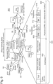
- Figure 8 shows peer delay messaging to evaluate the link delay.
- the solutions allow to have access to an accurate time sync reference (in the sub-microsecond accuracy) at all Remote Switches.
- the clients carry their own timestamps
- the clients are represented in Figure 6 as the packets, 608 - 614, located in the payload, 604, section of the frame 606.
- packets 608 - 614
- a timestamp is being considered to be carried in the mapped C2 frame.
- a contribution "RoE timestamp and presentation time in past”, by Jouni Korhonen to IEEE 1914.3 draft standard has proposed a 16 ms periodic timestamp that is sufficient to schedule the data on the 10 ms radio frame and that can be sufficient in a fronthaul network with hundreds ⁇ s (microseconds) max delay, see Figure 7 .
- timestamps have been defined to carry time sync information.
- IEEE 1588 ver. 2008 uses the following data type for a timestamp:
- the secondsField member is the integer portion of the timestamp in units of seconds.
- the nanosecondsField member is the fractional portion of the timestamp in units of nanoseconds.
- the nanosecondsField member is always less than 10 9 . Fractional nanoseconds cannot be represented in the IEEE 1588 Timestamp data type illustrated above and are transmitted in a correctionField , leaving it to the receiving device to combine the two to get the actual timestamp (8 octets).
- Timestamp data type represents a positive time with respect to the epoch.
- IEEE 1904.3 (now draft IEEE 1914.3) a specific timestamp associated with the mapped client is being defined. 30 bits are allocated for the actual timestamp, 72, as illustrated in Figure 7 .
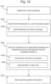
- Figure 14 shows an embodiment of a method of supporting latency monitoring in a transport network.
- the transport network, 600 illustrated in Figure 6 , is for transporting traffic to/from at least one wireless base station, 56.
- the method is performed at a first node, 58, of the transport network, 600.
- the method comprises an operation of determining, 1401, a first timestamp representing a time at which a data element is received at the first node, 58.
- the method comprises adding, 1402, the first timestamp to a communication signal which carries data for the at least one wireless base station, the data includes the data element.
- the method in this embodiment also comprises sending, 1403, an indication of an association between the timestamp and the data element that the timestamp relates to.
- the operation of sending, 1403, comprises sending the communication signal comprising an indication of the association between the timestamp and the data element that the timestamp relates to.
- the communication signal may comprise a frame, 606, with an overhead, 602, and a payload, 604.
- the method may add, at step 1404, the timestamp into the overhead part of the frame.
- the timestamp may be added to the payload, 604.
- the timestamp is sent in every C2 packet as it is used by the RRU, 55, to reconstruct the timing when data has to be delivered over radio interface.
- the indication of an association may be a pointer
- the method may, at 1405, add the pointer to an overhead part of the communication signal, the pointer pointing to a part of the payload where the timestamped data element (e.g. timestamped packet) is carried.
- the method may add an identifier, 1406, of a client link carried by the frame.
- the identifier indicates the client link that the timestamp relates to.
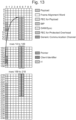
- Figure 13 One possible embodiment is illustrated in Figure 13 . All the timestamp information is in column 0, while the long rectangles in column 5 and 6 (but they could be also in other columns except in column 0) illustrate the packet being timestamped. Note that the packets are sent in the payload as we are using here a Time Division Multiplexed scheme to carry different clients.
- a single cell in the frame structure illustrated in Figure 13 corresponds to one byte of information.
- the information that is carried in column 0 for timestamping is divided into three fields:
- the method may send, 1407, synchronisation information.
- the synchronisation allows a second node (remote from the first node) to determine an accurate time of receipt of the data element, and therefore determine an accurate measure of latency.
- the synchronisation information may comprise at least one of an indication of time of day; peer delay messaging as specified in IEEE 1588 ver. 2008; an indication of status (traceability, fault, etc.).
- Figure 15 illustrates embodiment of the method as implemented at the second node, 54, which is remote from the first node, 58.
- Figure 15 shows an embodiment of a method of supporting latency monitoring in a transport network, 600.
- the transport network is for transporting traffic to/from at least one wireless base station, 56.
- the transport network, 600 comprises a first node, 58, and a second node, 54.
- the method in this embodiment is performed at the second node, 54.
- the method comprises receiving, 1501, a communication signal which carries data for the at least one wireless base station, 56.
- the data includes a data element.
- the method comprises extracting, 1502, a first timestamp from the communication signal.
- the first timestamp represents a time at which the data element was received at the first node, 58.
- the method comprises receiving, 1503, an indication of an association between the first timestamp and the data element that the first timestamp relates to.
- the method also comprises determining, 1504, a second timestamp representing a time at which the data element is received at the second node.
- the method comprises determining, 1505, a difference between the second timestamp and the first timestamp, the difference representing latency of the data element.
- the method may receive 1506 synchronisation information.
- the synchronisation information allows the second node to determine an accurate time of receipt of the data element, and therefore determine an accurate measure of latency.
- One embodiment is the PTP GM procedure mentioned earlier.
- the synchronisation information may comprise at least one of: an indication of time of day; peer delay messaging; an indication of status.
- the method may extract the first timestamp from an overhead part of the communication signal or from the payload in an alternative embodiment.
- the indication of an association may comprise a pointer in an overhead part of the communication signal, the pointer pointing to a part of the payload where the timestamped data element is carried.
- the indication of an association may be received in advance of the first timestamp.
- the communication signal may be a signal for carrying fronthaul data and backhaul data.
- the communication signal may comprise a frame with an overhead and a plurality of payload areas into which signals/data can be mapped, the payload areas comprising one or more of a payload area for carrying Common Public Radio Interface, CPRI, signals, a payload area for carrying Ethernet signals, a payload area for carrying C2 signals.
- CPRI Common Public Radio Interface
- a specific packet is timestamped at the entrance of the XHAUL network (packet timestamp t 1 ) and then the same packet is timestamped at the exit of the XHAUL network (packet timestamp t 2 ).
- the method then comprises associating these timestamps (ti and t 2 ) to an identifier of the specific packet that has been timestamped is one first possibility.
- a possible identifier could be a client timestamp TSi assuming this is unique per packet.
- TSi may indicate a predefined time instant when the data (i.e. packet timestamped with TSi) has to be presented at a certain point in the network.
- Implementation of the TSi timestamp is not fully standardized, eCPRI leaves the details to individual vendor implementation and the draft IEEE 1914.3 assumes that the TSi timestamp can be associated to each packet indicating when packet needs to be delivered over the radio interface.
- first timestamp and seconf timestamp may be modified by using information representative of a timestamp.
- the information representative of a timestamp may be the timestamp itself as in the embodiments already described.
- the information representative of a timestamp may be result of a modulo operation performed on the values of the timestamps.
- modulo 16 (16ms, milliseconds) value of the timestamp may be used similarly to the actual timestamp of the client (assuming that the network would not allow for latency larger than 16ms).
- modulo 16 calculated from a timestamp instead of the timestamp itself is that the modulo value is much shorter that the timestamp.
- modulo 16 it will be integer values from 0 to 15. This, in turn, allows for reducing the amount of data transmitted in order to determine latency in various embodiments of this invention.
- calculating the modulo value it is the value of 16 taken and not the unit (milliseconds), but in order to illustrate the relation between these operations and the time domain a notation is used showing the unit, ms, as in the equation (1) below.
- modulo values in latency measurement other modulo values may be used, based for example on 14ms, 18ms or 23ms, or some other values (i.e. mod14, mod18, mod23, etc).
- modulo 16 works under the assumption that the network would not allow for latency larger than 16ms.
- this limit may be different in embodiments using different modulo values as discussed above. If there is no such limitation (i.e. the network allows for larger latency than the one used in the modulo value) then a larger space in the packet for transmission of the timestamp infoprmation will be required (i.e. more bits), when the actual timestamps will be transmitted instead of their modulo values.
- modulo values instead of actual values of timestamps (e.g. t 1 and t 2 ) is an advantageous embodiment as it reduces the amount of data to be transmitted and simplifies its format, but is not essential for the operation of this invention.
- the latency may also be calculated as t 2 - t 1 .
- the specific packet being monitored is identified at both ends of the network; e.g. the value t 1 produced at the first node, 58, is carried associated to a specific parameter that is unique per packet (e.g. sequence number, timestamp TSi if this is unique per packet so that can be used as a packet identifier) and is compared with the instant t 2 related to the exit of the same frame at the remote end, i.e. at the second node, 54.
- a specific parameter that is unique per packet e.g. sequence number, timestamp TSi if this is unique per packet so that can be used as a packet identifier
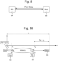
- Figure 9 shows delay monitoring at the Hub/RS (i.e. first node 58 and second node 54).
- This solution is applicable to any packet-based client for which there is a need to monitor the latency (for example, but not necessarily, C2).
- a centralized entity may be involved (e.g. NMS controller) in the collection and analysis of the monitoring data t 1 and t 2 .
- the timestamping information could be collected and analyzed by the Hub (for both directions latency measurements).
- the timestamps t 1 and t 2 are generated separately by the two nodes (Hub and RS). Only when these two timestamps are available the information is collected and analysed by the Hub or NMS.
- T RS-RRU the time period a packet needs to travel from the remote switch to the RRU output
- DU Digital Unit
- This special solution may imply some constraints in the TSi specification (e.g. that the TSi must be directly related to the absolute time when a packet is delivered).
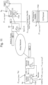
- the latency evaluation could be done including also these additional network elements, see example in Figure 11 (example with E-RAN switch). This require some messaging channel in the C2 mapping Header (indicated by field 1102 in figure 11 ). Also in this embodiment the measurements could be collected in a centralized node or at the E-RAN switch in the Hub site.
- the monitoring function may also be fully done within the radio domain by the BBU/RRU pair, 1202 and 1204, as shown in Figure 12 .
- the timestamp TSi could be just be part of the C2 Payload (see field "TSi" in the Eth mapping header of Figure 11 ).
- the C2 payload in addition to carry the Timestamp, could also be used to carry the actual timestamp to be monitored (ti, see field 1202 in figure 12 ). Also in this case it could be Tsi itself.
- the Time Division Multiplexing based framing associates a specific portion (that is an integer fraction) of the link bandwidth to a specific client.
- a fixed portion of the link bandwidth is not used for client payload but is dedicated to a service channel that is used to carry auxiliary information including, but not limited to, Forward Error Correction code-words (if used), in-band Operation and Maintenance (OAM) channel, quality monitoring functions (BIP, or bit-interleaved parity), frame alignment and frame numbering (in a multi-frame scheme).
- auxiliary information including, but not limited to, Forward Error Correction code-words (if used), in-band Operation and Maintenance (OAM) channel, quality monitoring functions (BIP, or bit-interleaved parity), frame alignment and frame numbering (in a multi-frame scheme).
- the time instant when the packet is ready to be transmitted towards the client is measured, leading to obtaining t 2mod16ms value that can be compared with t 1mod16ms extracted by the frame service channel to perform the latency monitoring function.
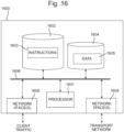
- Figure 16 shows one embodiment of an apparatus, 1600, for supporting latency monitoring at a first node of a transport network.
- the transport network is illustrated in one embodiment in Figure 6 .
- the transport network, 600 transports traffic to/from at least one wireless base station, 56.
- the apparatus comprises a processing circuitry, including one or more processors, 1601, and a memory, 1602.
- the memory contains instructions, 1603, executable by the processing circuitry, 1601.
- the apparatus, 1600 is operative to determine a first timestamp representing a time at which a data element is received at the first node, 58.
- the apparatus, 1600 is operative to add the first timestamp to a communication signal which carries data for the at least one wireless base station, 56, the data including the data element.
- the apparatus, 1600 is operative to send an indication of an association between the timestamp and the data element that the timestamp relates to.
- the apparatus, 1600 comprises one or more network interfaces, 1608, for interfacing with other network entities, such as links which carry client traffic.
- the apparatus, 1600 comprises one or more network interfaces 1609 for interfacing with the transport network, 600.
- the interfaces, 1608 and 1609, processor, 1601 and memory, 1602 and 1604 are connected to a bus, 1606, however, other architectures of the apparatus, 1600, are also possible and would be envisaged by those skilled in the art.
- the processor, memory modules and interfaces could be connected in series.
- Figure 17 shows one embodiment of an apparatus, 1700, for supporting latency monitoring at a second node of a transport network.
- the transport network is illustrated in one embodiment in Figure 6 .
- the transport network, 600 transports traffic to/from at least one wireless base station, 56.
- the apparatus, 1700 is provided at the second node, 54, of the transport network, 600, such as a remote node (remote switch).
- the apparatus, 1700 comprises a processing circuitry, including one or more processors, 1701, and a memory, 1702.
- the memory contains instructions, 1703, executable by the processing circuitry, 1701.
- the apparatus, 1700 is operative to receive a communication signal which carries data for the at least one wireless base station, 56, the data includes a data element.
- the apparatus, 1700 is operative to extract a first timestamp from the communication signal, wherein the first timestamp represents a time at which the data element was received at the first node, 58.
- the apparatus is operative to receive an indication of an association between the first timestamp and a part of the communication signal that the first timestamp relates to.
- the apparatus, 1700 is operative to determine a second timestamp representing a time at which the data element is received at the second node.
- the apparatus, 1700 comprises one or more network interfaces, 1708, for interfacing with the transport network.
- the apparatus, 1700 comprises one or more network interfaces, 1709, for interfacing with other network entities, such as links which connect the second node, 54, to wireless base stations (e.g. the base station 56).
- the interfaces, 1708 and 1709, processor, 1701 and memory, 1702 and 1704 are connected to a bus, 1706, however, other architectures of the apparatus, 1700, are also possible and would be envisaged by those skilled in the art.
- the processor, memory modules and interfaces could be connected in series.
- processor 1601, 1701 comprises one or more processors which may be microprocessors, controllers or any other suitable type of processors for executing instructions to control the operation of the device.
- the processor is connected to other components of the device via one or more buses 1606, 1706.
- Processor-executable instructions 1603, 1703 may be provided using any computer-readable media, such as memory 1602, 1702.
- the processor-executable instructions can comprise instructions for implementing the functionality of the described methods.
- the memory 1602, 1702 is of any suitable type such as read-only memory (ROM), random access memory (RAM), a storage device of any type such as a magnetic or optical storage device. Additional memory 1604, 1704 can be provided to store data 1605, 1705 used by the processor 1601, 1701.
- a solution as described above may provide accurate latency monitoring for packet based client links used for radio fronthauling or other time sensitive application.
- FIG. 18A there are two types of wireless base station in the network.
- the two types of wireless base station are shown in Figure 18A and Figure 18B .
- the functionality of the wireless base station is split between a remote radio unit (RRU) 3 and a digital unit (DU) 4.
- the DU 4 is configured to perform processing at baseband and to output digital baseband IQ data (i.e. real and imaginary components of the complex-valued baseband signal).
- the RRU 3 is configured to transmit an RF signal using the IQ data received from the DU 4.
- the RRU 3 is configured to receive an RF signal and output IQ data of the received signal to the DU 4 for baseband processing.
- a CPRI interface carries the IQ data. Several IQ data flows are sent via one physical CPRI link, 21.
- Each IQ data flow reflects the data of one antenna for one carrier, the so-called antenna-carrier (AxC).
- AxC antenna-carrier
- Each RRU 3 may receive and send multiple AxC sub-flows.
- the traffic between DU 4 and RRU 3 (in either direction) is called fronthaul traffic.
- the RRU 3 may alternatively be called Radio Equipment (RE).
- the DU 4 may alternatively be called a Main Unit (MU), Radio Equipment Controller (REC) or Baseband Unit (BBU).
- the RRU 3 communicates with a DU 4 using an interface standard, such as CPRI. References to CPRI are for example only, and may be replaced with a reference to any interface protocol for carrying data (e.g.
- Clock 31 provides a frequency reference for the RRU, such as when generating RF signals.
- Clock 31 also provides a phase reference for timing purposes, such as timing of RF transmissions.
- the second type of wireless base station 6, shown in Figure 18B does not have the split of radio (RF) and baseband functionality. Instead, in the wireless base station 6 all of the functionality of the wireless base station is combined.
- the radio unit (RF unit or radio frequency unit) and baseband processing unit are co-located.
- co-located means the radio functionality and baseband processing unit at the same cell site. It will be understood that there may be a small physical separation between the radio unit (RF unit) and the baseband processing unit at a cell site. For example, a radio unit may be located at the top of a tower or building and a baseband processing unit may be located at the base of the tower or building. This type of separation falls within the term "co-located".
- the wireless base station receives data, performs processing at baseband, and transmits/receives RF signals.
- This type of wireless base station is an integrated, or monolithic, base station and will be referred to as a radio base station RBS 6.
- An RBS 6 does not output a CPRI signal, since the baseband processing is implemented internally.
- An RBS 6 outputs and receives data in a different format than used by a RRU for radio transmission or baseband processing (e.g. CPRI).
- the traffic carried over the transport network 20 to and/or from the RBS 6 is called backhaul traffic.
- the RBS 6 communicates with the core network and other base stations. In some examples, the RBS 6 communicates with the core network and other base stations using the same transport protocol for at least some transport layers.
- the RBS 6 uses a packet based data transport.
- the RBS 6 uses Ethernet, as defined by IEEE 802.1 and IEEE 802.3. References to Ethernet are for example only, and may be replaced with a reference to any protocol for exchanging data to or from a radio base station, for example, packet transport.
- the transport connecting a base station may be based on a Layer 2 protocol on the Open Systems Interconnection model (OSI) model, or on a Layer 3 protocol.
- the RBS 6 may be a base station providing a micro cell or a pico cell, such as localised indoor coverage.
- a clock 32 is maintained at the RBS 6.
- Clock 32 provides a frequency reference for the RBS, such as when generating RF signals.
- Clock 32 also provides a phase reference for timing purposes, such as timing of RF transmissions.
- Base stations RBS 6 (with baseband processing) and RRUs 3 (without baseband processing) may both be considered as radio equipment.
- FIGs 19A-19C illustrate three types of synchronisation in a network: frequency synchronisation ( Figure 19A ); phase synchronisation ( Figure 19B ); and time synchronisation ( Figure 19C ).
- Two clocks are considered: a clock A at a first node and a clock B at a second node.
- a time line of each clock A, B shows a series of clock "ticks".
- a clock tick could occur at a granularity of a second, a minute or some other granularity of time.
- FIG 19A shows frequency synchronisation.
- T A 1/f A
- FIG 19B shows phase synchronisation.
- the clock ticks are aligned in time with one another. That is, the clock tick at clock A occurs at the same point in time as the clock tick at clock B.
- Figure 19C shows time synchronisation. This is the same as phase synchronisation, with the additional feature that both clocks are set to the same time (e.g. time of day). In this example, a tick occurs at both clocks at the same time, and both clocks are aware that the time is 08:13:12.
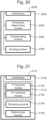
- Figure 20 illustrates yet another embodiment of an apparatus for supporting latency monitoring at a first node of a transport network.
- the transport network transports traffic (packets) to and from at least one wireless base station.
- the apparatus, 2000 comprises a timestamp determining module, 2002, for determining a first timestamp representing a time at which a data element is received at the first node.
- the apparatus 2000 also comprises a timestamping module for adding information representative of the first timestamp to a communication signal which carries data for the at least one wireless base station (the data includes the data element) and further comprises a sending module for sending an indication of an association between the information representative of the first timestamp and the data element that the information representative of the first timestamp relates to.
- Figure 21 illustrates yet another embodiment of an apparatus, 2100, for supporting latency monitoring at a second node of a transport network.
- the transport network transports traffic to and from at least one wireless base station and comprises a first node and the second node.
- the apparatus, 2100 comprises a first receiving module, 2102, for receiving a communication signal which carries data for the at least one wireless base station, wherein the data includes a data element.
- the apparatus, 2100 also comprises an extracting module, 2106, for extracting information representative of a first timestamp from the communication signal. The first timestamp representing a time at which the data element was received at the first node.
- the apparatus, 2100 comprises a second receiving module, 2104, for receiving an indication of an association between the information representative of the first timestamp and a part of the communication signal that the information representative of the first timestamp relates to and a determining module, 2108, for determining information representative of a second timestamp representing a time at which the data element is received at the second node.
- first receiving module, 2102, and the second receiving module, 2104 are integrated into a single module, 2112.
- the interfaces 2008 and 2110 serve for connecting traffic to and from the transport network as well as to and from the base station(s). These interfaces may be implemented as combined units (i.e. one interface serving traffic to/from transport network and to/from base station(s)) or as separate units similar to the embodiments illustrated in Figures 16 and 17 .
- the interfaces as well as remaining modules are connected to a bus, however, other architectures of the apparatus, 2000 and 2100, are also possible and would be envisaged by those skilled in the art.
- the modules and interfaces could be connected in series.
- the apparatus, 2000 and 2001, illustrated in Figures 20 and 21 are configured to operated according to their corresponding methods (i.e. for first node and second node) described earlier in this document.
Landscapes
- Engineering & Computer Science (AREA)
- Computer Networks & Wireless Communication (AREA)
- Signal Processing (AREA)
- Environmental & Geological Engineering (AREA)
- Health & Medical Sciences (AREA)
- Cardiology (AREA)
- General Health & Medical Sciences (AREA)
- Mobile Radio Communication Systems (AREA)
Claims (17)
- Verfahren zur Verwendung in einem ersten Knoten eines Transportnetzwerks zum Unterstützen von Latenzüberwachung in dem Transportnetzwerk, wobei das Transportnetzwerk Verkehr zu und von mindestens einer drahtlosen Basisstation transportiert, wobei das Transportnetzwerk den ersten Knoten und einen zweiten Knoten umfasst, wobei das Verfahren umfasst:Bestimmen (1401) eines ersten Zeitstempels, der einen Zeitpunkt darstellt, zu dem ein Datenelement an dem ersten Knoten empfangen wird;Hinzufügen (1402) des ersten Zeitstempels zu einem Kommunikationssignal zum Senden an den zweiten Knoten, wobei das Kommunikationssignal Daten für die mindestens eine drahtlose Basisstation überträgt, wobei die Daten das empfangene Datenelement umfassen; undSenden (1403) einer Angabe einer Verknüpfung zwischen dem ersten Zeitstempel und dem Datenelement, das der erste Zeitstempel betrifft, wobei die Angabe einer Verknüpfung ein Zeiger ist, der auf einen Teil einer Nutzlast zeigt, in der das zeitgestempelte Datenelement übertragen wird.
- Verfahren nach Anspruch 1, wobei das Kommunikationssignal einen Rahmen mit Verwaltungsdaten und einer Nutzlast umfasst, und das Verfahren den ersten Zeitstempel zu dem Verwaltungsdatenteil des Rahmens hinzufügt (1404).
- Verfahren nach Anspruch 2, wobei die Angabe einer Verknüpfung ein Zeiger ist, und das Verfahren das Hinzufügen des Zeigers (1405) zu einem Verwaltungsdatenteil des Kommunikationssignals umfasst, wobei der Zeiger auf einen Teil der Nutzlast zeigt, in dem das Datenelement übertragen wird.
- Verfahren nach einem der Ansprüche 1 bis 3, wobei die Angabe einer Verknüpfung eine Kennung eines Client-Links umfasst, die von dem Rahmen übertragen wird.
- Verfahren nach einem der Ansprüche 1 bis 4, umfassend:
Senden von Synchronisationsinformationen. - Verfahren zur Verwendung in einem zweiten Knoten eines Transportnetzwerks zum Unterstützen von Latenzüberwachung in dem Transportnetzwerk, wobei das Transportnetzwerk Verkehr zu und von mindestens einer drahtlosen Basisstation transportiert, wobei das Transportnetzwerk einen ersten Knoten und den zweiten Knoten umfasst, wobei das Verfahren umfasst:Empfangen (1501) eines Kommunikationssignals, das Daten für die mindestens eine drahtlose Basisstation überträgt, wobei die Daten ein Datenelement umfassen;Entnehmen (1502) eines ersten Zeitstempels aus dem Kommunikationssignal, wobei der erste Zeitstempel einen Zeitpunkt darstellt, zu dem das Datenelement an dem ersten Knoten empfangen wurde;Empfangen (1503) einer Angabe einer Verknüpfung zwischen dem ersten Zeitstempel und dem Datenelement, das der erste Zeitstempel betrifft, wobei die Angabe einer Verknüpfung ein Zeiger ist, der auf einen Teil einer Nutzlast zeigt, in dem das zeitgestempelte Datenelement übertragen wird;Bestimmen (1504) eines zweiten Zeitstempels, der einen Zeitpunkt darstellt, zu dem das Datenelement an dem zweiten Knoten empfangen wird.
- Verfahren nach Anspruch 6, wobei die Angabe einer Verknüpfung einen Zeiger in einem Verwaltungsdatenteil des Kommunikationssignals umfasst, wobei der Zeiger auf einen Teil der Nutzlast zeigt, in dem das Datenelement übertragen wird.
- Verfahren nach Anspruch 7, wobei die Angabe einer Verknüpfung im Voraus vor dem ersten Zeitstempel empfangen wird.
- Verfahren nach einem der Ansprüche 1 bis 8, wobei das Kommunikationssignal ein Signal zum Übertragen von Fronthaul-Daten und Backhaul-Daten ist.
- Verfahren nach einem der Ansprüche 1 bis 9, wobei das Kommunikationssignal einen Rahmen mit Verwaltungsdaten und einer Vielzahl von Nutzlastbereichen, denen Signale/Daten zugeordnet werden können, umfasst, wobei die Nutzlastbereiche einen oder mehrere umfassen von:einem Nutzlastbereich zum Übertragen von gemeinsamen öffentlichen Funkschnittstellen-, CPRI, Signalen;einem Nutzlastbereich zum Übertragen von Ethernet-Signalen.
- Gerät (1600) zum Unterstützen von Latenzüberwachung an einem ersten Knoten eines Transportnetzwerks, wobei das Transportnetzwerk Verkehr zu und von mindestens einer drahtlosen Basisstation transportiert, wobei das Transportnetzwerk den ersten Knoten und einen zweiten Knoten umfasst, wobei das Gerät (1600) Verarbeitungsschaltungen (1601) und einen Speicher (1602) umfasst, wobei der Speicher (1602) Anweisungen enthält, die durch die Verarbeitungsschaltungen (1601) durchführbar sind, so dass das Gerät (1600) betriebsfähig ist zum:Bestimmen eines ersten Zeitstempels, der einen Zeitpunkt darstellt, zu dem ein Datenelement an dem ersten Knoten empfangen wird;Hinzufügen des ersten Zeitstempels zu einem Kommunikationssignal zum Senden an den zweiten Knoten, wobei das Kommunikationssignal Daten für die mindestens eine drahtlose Basisstation überträgt, wobei die Daten das empfangene Datenelement umfassen; undSenden einer Angabe einer Verknüpfung zwischen dem ersten Zeitstempel und dem Datenelement, das der erste Zeitstempel betrifft, wobei die Angabe einer Verknüpfung ein Zeiger ist, der auf einen Teil einer Nutzlast zeigt, in der das zeitgestempelte Datenelement übertragen wird.
- Gerät (1600) nach Anspruch 11, wobei das Kommunikationssignal einen Rahmen mit Verwaltungsdaten und einer Nutzlast umfasst, und das Gerät (1600) betriebsfähig ist, den ersten Zeitstempel zu dem Verwaltungsdatenteil des Rahmens hinzuzufügen.
- Gerät (1600) nach Anspruch 12, wobei die Angabe einer Verknüpfung ein Zeiger ist, und das Gerät (1600) betriebsfähig ist, den Zeiger zu einem Verwaltungsdatenteil des Kommunikationssignals hinzuzufügen, wobei der Zeiger auf einen Teil der Nutzlast zeigt, in dem das Datenelement übertragen wird.
- Gerät (1600) nach einem der Ansprüche 11 bis 13, das betriebsfähig ist, eine Kennung eines Client-Links, die von dem Rahmen als Angabe einer Verknüpfung übertragen wird, zu verwenden.
- Gerät (1700) zum Unterstützen von Latenzüberwachung an einem zweiten Knoten eines Transportnetzwerks, wobei das Transportnetzwerk Verkehr zu und von mindestens einer drahtlosen Basisstation transportiert, wobei das Transportnetzwerk einen ersten Knoten und den zweiten Knoten umfasst, wobei das Gerät (1700) Verarbeitungsschaltungen (1701) und einen Speicher (1702) umfasst, wobei der Speicher (1702) Anweisungen enthält, die durch die Verarbeitungsschaltungen (1701) durchführbar sind, so dass das Gerät (1700) betriebsfähig ist zum:Empfangen eines Kommunikationssignals, das Daten für die mindestens eine drahtlose Basisstation überträgt, wobei die Daten ein Datenelement umfassen;Entnehmen eines ersten Zeitstempels aus dem Kommunikationssignal, wobei der erste Zeitstempel einen Zeitpunkt darstellt, zu dem das Datenelement an dem ersten Knoten empfangen wurde;Empfangen einer Angabe einer Verknüpfung zwischen dem ersten Zeitstempel und dem Datenelement, das der erste Zeitstempel betrifft, wobei die Angabe einer Verknüpfung ein Zeiger ist, der auf einen Teil einer Nutzlast zeigt, in dem das zeitgestempelte Datenelement übertragen wird;Bestimmen eines zweiten Zeitstempels, der einen Zeitpunkt darstellt, zu dem das Datenelement an dem zweiten Knoten empfangen wird.
- Gerät (1700) nach Anspruch 15, wobei die Angabe einer Verknüpfung einen Zeiger in einem Verwaltungsdatenteil des Kommunikationssignals umfasst, wobei der Zeiger auf einen Teil der Nutzlast zeigt, in dem das Datenelement übertragen wird.
- Gerät (1700) nach Anspruch 16, das betriebsfähig ist, die Angabe einer Verknüpfung im Voraus vor dem ersten Zeitstempel zu empfangen.
Priority Applications (1)
| Application Number | Priority Date | Filing Date | Title |
|---|---|---|---|
| EP23204465.1A EP4287532B1 (de) | 2016-12-06 | 2017-12-01 | Verfahren und vorrichtung zur latenzüberwachung |
Applications Claiming Priority (2)
| Application Number | Priority Date | Filing Date | Title |
|---|---|---|---|
| US201662430607P | 2016-12-06 | 2016-12-06 | |
| PCT/EP2017/081213 WO2018104175A1 (en) | 2016-12-06 | 2017-12-01 | Method and apparatus for latency monitoring |
Related Child Applications (1)
| Application Number | Title | Priority Date | Filing Date |
|---|---|---|---|
| EP23204465.1A Division EP4287532B1 (de) | 2016-12-06 | 2017-12-01 | Verfahren und vorrichtung zur latenzüberwachung |
Publications (2)
| Publication Number | Publication Date |
|---|---|
| EP3552355A1 EP3552355A1 (de) | 2019-10-16 |
| EP3552355B1 true EP3552355B1 (de) | 2023-11-01 |
Family
ID=60888358
Family Applications (2)
| Application Number | Title | Priority Date | Filing Date |
|---|---|---|---|
| EP23204465.1A Active EP4287532B1 (de) | 2016-12-06 | 2017-12-01 | Verfahren und vorrichtung zur latenzüberwachung |
| EP17822559.5A Active EP3552355B1 (de) | 2016-12-06 | 2017-12-01 | Verfahren und vorrichtung zur latenzüberwachung |
Family Applications Before (1)
| Application Number | Title | Priority Date | Filing Date |
|---|---|---|---|
| EP23204465.1A Active EP4287532B1 (de) | 2016-12-06 | 2017-12-01 | Verfahren und vorrichtung zur latenzüberwachung |
Country Status (6)
| Country | Link |
|---|---|
| US (2) | US11088930B2 (de) |
| EP (2) | EP4287532B1 (de) |
| CN (1) | CN110291758B (de) |
| ES (2) | ES2966085T3 (de) |
| PL (1) | PL3552355T3 (de) |
| WO (1) | WO2018104175A1 (de) |
Families Citing this family (26)
| Publication number | Priority date | Publication date | Assignee | Title |
|---|---|---|---|---|
| WO2016145371A2 (en) | 2015-03-11 | 2016-09-15 | Phluido, Inc. | Distributed radio access network with adaptive fronthaul |
| WO2018017468A1 (en) | 2016-07-18 | 2018-01-25 | Phluido, Inc. | Synchronization of radio units in radio access networks |
| PL3552355T3 (pl) * | 2016-12-06 | 2024-03-25 | Telefonaktiebolaget Lm Ericsson (Publ) | Sposób i aparat do monitorowania zwłoki |
| EP3659277A1 (de) | 2017-07-25 | 2020-06-03 | Telefonaktiebolaget LM Ericsson (publ.) | Verfahren, vorrichtung und computerlesbare medien zur synchronisation über ein optisches netzwerk |
| EP3711265A1 (de) | 2017-11-13 | 2020-09-23 | Telefonaktiebolaget LM Ericsson (PUBL) | Verfahren und vorrichtung zur verwaltung des transports von verzögerungsempfindlichen paketen |
| US12016084B2 (en) | 2018-01-04 | 2024-06-18 | Commscope Technologies Llc | Management of a split physical layer in a radio area network |
| WO2019158205A1 (en) | 2018-02-15 | 2019-08-22 | Telefonaktiebolaget Lm Ericsson (Publ) | Method and device for forwarding a digital signal |
| CN111107621B (zh) * | 2018-10-29 | 2021-02-26 | 大唐移动通信设备有限公司 | 一种同步方法及装置 |
| US11395242B2 (en) | 2019-02-01 | 2022-07-19 | Cisco Technology, Inc. | Link establishment between a radio equipment controller (REC) and radio equipment (RE) in a fronthaul network |
| CN109959903B (zh) * | 2019-03-07 | 2023-04-07 | 南京莱斯信息技术股份有限公司 | 一种在线检测雷达数据传输时延装置及检测方法 |
| US10594423B1 (en) | 2019-09-09 | 2020-03-17 | Cisco Technology, Inc. | Re-timing a packetized radio flow to clean noise induced by packet delay variation of a packet network |
| US10863386B1 (en) | 2019-09-17 | 2020-12-08 | Cisco Technology, Inc. | State machine handling at a proxy node in an ethernet-based fronthaul network |
| CN112583477B (zh) * | 2019-09-27 | 2023-08-04 | 深圳市中兴微电子技术有限公司 | 一种延时测量方法、系统和存储介质 |
| CN112672235B (zh) * | 2019-10-15 | 2024-11-26 | 中兴通讯股份有限公司 | 一种同步方法、装置、设备和存储介质 |
| CN113079533A (zh) * | 2020-01-03 | 2021-07-06 | 中国移动通信有限公司研究院 | 一种监控信息处理方法和相关设备 |
| CN113905399B (zh) * | 2020-07-06 | 2024-10-18 | 中国移动通信有限公司研究院 | 一种时延处理方法、设备、装置及介质 |
| US11223437B1 (en) * | 2020-08-24 | 2022-01-11 | Ciena Corporation | Differential clock recovery using a global reference time |
| CN114205428B (zh) * | 2020-08-28 | 2024-03-01 | 华为技术有限公司 | 确定空口时延的方法及装置 |
| US12047785B2 (en) | 2020-09-09 | 2024-07-23 | Commscope Technologies Llc | Management plane functionality for switched network shared cell configuration of open radio access network (O-RAN) system |
| CN114698086B (zh) * | 2020-12-31 | 2024-11-08 | 中国移动通信有限公司研究院 | 信息指示方法、装置、相关设备及存储介质 |
| JP7721277B2 (ja) * | 2021-02-03 | 2025-08-13 | 株式会社東芝 | 共用装置、子機、管理装置、通信中継システムおよびプログラム |
| WO2023130217A1 (en) * | 2022-01-04 | 2023-07-13 | Telefonaktiebolaget Lm Ericsson (Publ) | Method and apparatus for radio over ethernet |
| CN116980324A (zh) * | 2022-04-24 | 2023-10-31 | 华为技术有限公司 | 一种时延测量方法以及相关设备 |
| CN117354152A (zh) * | 2022-06-27 | 2024-01-05 | 中兴通讯股份有限公司 | 维测时间的确定方法、装置和设备 |
| WO2025122140A1 (en) * | 2023-12-05 | 2025-06-12 | Rakuten Symphony, Inc. | Analyzing timing of packets in fronthaul |
| CN121239298A (zh) * | 2025-12-03 | 2025-12-30 | 中国电子科技集团公司第五十四研究所 | 一种高速卫星遥感数据传输时延实时检测方法 |
Family Cites Families (15)
| Publication number | Priority date | Publication date | Assignee | Title |
|---|---|---|---|---|
| US7839897B2 (en) * | 2006-09-29 | 2010-11-23 | Agere Systems Inc. | Methods and apparatus for unidirectional timing message transport over packet networks |
| DE602007010225D1 (de) * | 2006-10-18 | 2010-12-16 | Tellabs Oy | Synchronisationsverfahren und -anordnung |
| CN101247168B (zh) * | 2007-02-15 | 2012-04-25 | 华为技术有限公司 | 一种时间同步的方法及系统 |
| US8976680B2 (en) * | 2010-03-15 | 2015-03-10 | Juniper Networks, Inc. | Operations, administration, and management fields for packet transport |
| US9276831B2 (en) * | 2013-07-18 | 2016-03-01 | Airmagnet, Inc. | Determining network latency with limited computing resources |
| US9473261B1 (en) * | 2013-08-29 | 2016-10-18 | Microsemi Storage Solutions (U.S.), Inc. | System and method to achieve datapath latency symmetry through an OTN wrapper |
| US10135557B2 (en) | 2014-02-03 | 2018-11-20 | Telefonaktiebolaget Lm Ericsson (Publ) | Encapsulation of digital communications traffic for transmission on an optical link |
| CN106031134A (zh) * | 2014-02-26 | 2016-10-12 | 三菱电机株式会社 | 光传输系统以及延迟测定方法 |
| US20160006526A1 (en) * | 2014-07-03 | 2016-01-07 | Qualcomm Incorporated | Systems and methods of network clock comparison |
| WO2016005008A1 (en) | 2014-07-11 | 2016-01-14 | Telefonaktiebolaget L M Ericsson (Publ) | Optical transport network |
| US9525482B1 (en) * | 2015-02-09 | 2016-12-20 | Microsemi Storage Solutions (U.S.), Inc. | Apparatus and method for measurement of propagation time of a data stream in a transport network |
| WO2016138950A1 (en) | 2015-03-04 | 2016-09-09 | Telefonaktiebolaget Lm Ericsson (Publ) | Encapsulating digital communications signals for transmission on an optical link |
| EP3326412B1 (de) | 2015-07-17 | 2021-06-09 | Telefonaktiebolaget LM Ericsson (publ) | Synchronisation von drahtlosen basisstationen |
| EP3482521B1 (de) * | 2016-07-06 | 2020-09-02 | Telefonaktiebolaget LM Ericsson (publ) | Senden und empfangen von zeitstempelinformationen |
| PL3552355T3 (pl) * | 2016-12-06 | 2024-03-25 | Telefonaktiebolaget Lm Ericsson (Publ) | Sposób i aparat do monitorowania zwłoki |
-
2017
- 2017-12-01 PL PL17822559.5T patent/PL3552355T3/pl unknown
- 2017-12-01 WO PCT/EP2017/081213 patent/WO2018104175A1/en not_active Ceased
- 2017-12-01 ES ES17822559T patent/ES2966085T3/es active Active
- 2017-12-01 US US16/466,339 patent/US11088930B2/en active Active
- 2017-12-01 EP EP23204465.1A patent/EP4287532B1/de active Active
- 2017-12-01 EP EP17822559.5A patent/EP3552355B1/de active Active
- 2017-12-01 ES ES23204465T patent/ES3023683T3/es active Active
- 2017-12-01 CN CN201780085811.8A patent/CN110291758B/zh active Active
-
2021
- 2021-07-02 US US17/366,355 patent/US11811634B2/en active Active
Also Published As
| Publication number | Publication date |
|---|---|
| US11088930B2 (en) | 2021-08-10 |
| US20190342198A1 (en) | 2019-11-07 |
| ES2966085T3 (es) | 2024-04-18 |
| EP4287532C0 (de) | 2025-04-16 |
| US20210336864A1 (en) | 2021-10-28 |
| PL3552355T3 (pl) | 2024-03-25 |
| CN110291758A (zh) | 2019-09-27 |
| WO2018104175A1 (en) | 2018-06-14 |
| ES3023683T3 (en) | 2025-06-02 |
| EP3552355A1 (de) | 2019-10-16 |
| EP4287532A2 (de) | 2023-12-06 |
| EP4287532A3 (de) | 2024-03-06 |
| US11811634B2 (en) | 2023-11-07 |
| EP4287532B1 (de) | 2025-04-16 |
| CN110291758B (zh) | 2022-11-01 |
Similar Documents
| Publication | Publication Date | Title |
|---|---|---|
| US11811634B2 (en) | Method and apparatus for latency monitoring | |
| EP3491753B1 (de) | System und verfahren zur netzwerksynchronisierung | |
| EP2847921B1 (de) | Zeitsynchronisation für netzwerke mit funkverbindungen | |
| EP3820061B1 (de) | Verfahren und vorrichtung zur korrektur der zeitsynchronisationsabweichung, endgerät und zugriffsschichtvorrichtung | |
| EP3326412B1 (de) | Synchronisation von drahtlosen basisstationen | |
| EP3277034B1 (de) | Verfahren und system zur zeitsynchronisation sowie netzwerkvorrichtung | |
| US8971357B2 (en) | Method for synchronizing master and slave clocks of a packet-switched network with aggregated connections between nodes, and associated synchronization devices | |
| CN101778405B (zh) | 结构健康监测的无线传感器网络同步采集方法及系统 | |
| CN102843620B (zh) | 一种实现时间同步传送的otn设备及方法 | |
| EP2856673B1 (de) | Verteilung von taktsynchronisationsinformationen in einem optischen übertragungsnetzwerk | |
| US20120148248A1 (en) | Transport device and clock and time synchronization method thereof | |
| US11683150B2 (en) | Methods, apparatus and computer-readable media for synchronization over an optical network | |
| JP4509921B2 (ja) | 無線通信システムおよび無線通信方法 | |
| CN103152118B (zh) | 一种基带单元和射频单元数据业务同步方法、装置和系统 | |
| CN106375054A (zh) | Otn网元设备、otn时钟和时间的同步方法及系统 | |
| US20130315606A1 (en) | Distributing clock synchronization information within an optical communications network | |
| CN101998192A (zh) | 无源光网络上时间同步的方法和系统 | |
| Schüngel et al. | Single message distribution of timing information for time synchronization in converged wired and wireless networks | |
| CN110995387B (zh) | 一种gpon网络承载高精度时钟的实现方法 | |
| JP2019110417A (ja) | 時刻同期方法、時刻同期プログラム、および時刻同期装置、並びに、時刻同期システム | |
| Pietiläinen et al. | Synchronization |
Legal Events
| Date | Code | Title | Description |
|---|---|---|---|
| STAA | Information on the status of an ep patent application or granted ep patent |
Free format text: STATUS: UNKNOWN |
|
| STAA | Information on the status of an ep patent application or granted ep patent |
Free format text: STATUS: THE INTERNATIONAL PUBLICATION HAS BEEN MADE |
|
| PUAI | Public reference made under article 153(3) epc to a published international application that has entered the european phase |
Free format text: ORIGINAL CODE: 0009012 |
|
| STAA | Information on the status of an ep patent application or granted ep patent |
Free format text: STATUS: REQUEST FOR EXAMINATION WAS MADE |
|
| 17P | Request for examination filed |
Effective date: 20190606 |
|
| AK | Designated contracting states |
Kind code of ref document: A1 Designated state(s): AL AT BE BG CH CY CZ DE DK EE ES FI FR GB GR HR HU IE IS IT LI LT LU LV MC MK MT NL NO PL PT RO RS SE SI SK SM TR |
|
| AX | Request for extension of the european patent |
Extension state: BA ME |
|
| DAV | Request for validation of the european patent (deleted) | ||
| DAX | Request for extension of the european patent (deleted) | ||
| STAA | Information on the status of an ep patent application or granted ep patent |
Free format text: STATUS: EXAMINATION IS IN PROGRESS |
|
| 17Q | First examination report despatched |
Effective date: 20210414 |
|
| REG | Reference to a national code |
Ref country code: DE Ref legal event code: R079 Free format text: PREVIOUS MAIN CLASS: H04L0012260000 Ipc: H04W0088080000 Ref document number: 602017076069 Country of ref document: DE |
|
| RIC1 | Information provided on ipc code assigned before grant |
Ipc: H04J 3/14 20060101ALI20221205BHEP Ipc: H04W 88/08 20090101AFI20221205BHEP |
|
| GRAP | Despatch of communication of intention to grant a patent |
Free format text: ORIGINAL CODE: EPIDOSNIGR1 |
|
| STAA | Information on the status of an ep patent application or granted ep patent |
Free format text: STATUS: GRANT OF PATENT IS INTENDED |
|
| INTG | Intention to grant announced |
Effective date: 20230123 |
|
| GRAJ | Information related to disapproval of communication of intention to grant by the applicant or resumption of examination proceedings by the epo deleted |
Free format text: ORIGINAL CODE: EPIDOSDIGR1 |
|
| STAA | Information on the status of an ep patent application or granted ep patent |
Free format text: STATUS: EXAMINATION IS IN PROGRESS |
|
| INTC | Intention to grant announced (deleted) | ||
| GRAP | Despatch of communication of intention to grant a patent |
Free format text: ORIGINAL CODE: EPIDOSNIGR1 |
|
| STAA | Information on the status of an ep patent application or granted ep patent |
Free format text: STATUS: GRANT OF PATENT IS INTENDED |
|
| INTG | Intention to grant announced |
Effective date: 20230516 |
|
| P01 | Opt-out of the competence of the unified patent court (upc) registered |
Effective date: 20230716 |
|
| GRAS | Grant fee paid |
Free format text: ORIGINAL CODE: EPIDOSNIGR3 |
|
| GRAA | (expected) grant |
Free format text: ORIGINAL CODE: 0009210 |
|
| STAA | Information on the status of an ep patent application or granted ep patent |
Free format text: STATUS: THE PATENT HAS BEEN GRANTED |
|
| AK | Designated contracting states |
Kind code of ref document: B1 Designated state(s): AL AT BE BG CH CY CZ DE DK EE ES FI FR GB GR HR HU IE IS IT LI LT LU LV MC MK MT NL NO PL PT RO RS SE SI SK SM TR |
|
| REG | Reference to a national code |
Ref country code: GB Ref legal event code: FG4D |
|
| REG | Reference to a national code |
Ref country code: CH Ref legal event code: EP |
|
| REG | Reference to a national code |
Ref country code: IE Ref legal event code: FG4D |
|
| REG | Reference to a national code |
Ref country code: DE Ref legal event code: R096 Ref document number: 602017076069 Country of ref document: DE |
|
| REG | Reference to a national code |
Ref country code: NL Ref legal event code: FP |
|
| REG | Reference to a national code |
Ref country code: NO Ref legal event code: T2 Effective date: 20231101 |
|
| REG | Reference to a national code |
Ref country code: LT Ref legal event code: MG9D |
|
| PG25 | Lapsed in a contracting state [announced via postgrant information from national office to epo] |
Ref country code: GR Free format text: LAPSE BECAUSE OF FAILURE TO SUBMIT A TRANSLATION OF THE DESCRIPTION OR TO PAY THE FEE WITHIN THE PRESCRIBED TIME-LIMIT Effective date: 20240202 |
|
| PG25 | Lapsed in a contracting state [announced via postgrant information from national office to epo] |
Ref country code: IS Free format text: LAPSE BECAUSE OF FAILURE TO SUBMIT A TRANSLATION OF THE DESCRIPTION OR TO PAY THE FEE WITHIN THE PRESCRIBED TIME-LIMIT Effective date: 20240301 |
|
| PG25 | Lapsed in a contracting state [announced via postgrant information from national office to epo] |
Ref country code: LT Free format text: LAPSE BECAUSE OF FAILURE TO SUBMIT A TRANSLATION OF THE DESCRIPTION OR TO PAY THE FEE WITHIN THE PRESCRIBED TIME-LIMIT Effective date: 20231101 |
|
| REG | Reference to a national code |
Ref country code: AT Ref legal event code: MK05 Ref document number: 1628719 Country of ref document: AT Kind code of ref document: T Effective date: 20231101 |
|
| REG | Reference to a national code |
Ref country code: ES Ref legal event code: FG2A Ref document number: 2966085 Country of ref document: ES Kind code of ref document: T3 Effective date: 20240418 |
|
| PG25 | Lapsed in a contracting state [announced via postgrant information from national office to epo] |
Ref country code: AT Free format text: LAPSE BECAUSE OF FAILURE TO SUBMIT A TRANSLATION OF THE DESCRIPTION OR TO PAY THE FEE WITHIN THE PRESCRIBED TIME-LIMIT Effective date: 20231101 |
|
| PG25 | Lapsed in a contracting state [announced via postgrant information from national office to epo] |
Ref country code: LT Free format text: LAPSE BECAUSE OF FAILURE TO SUBMIT A TRANSLATION OF THE DESCRIPTION OR TO PAY THE FEE WITHIN THE PRESCRIBED TIME-LIMIT Effective date: 20231101 Ref country code: IS Free format text: LAPSE BECAUSE OF FAILURE TO SUBMIT A TRANSLATION OF THE DESCRIPTION OR TO PAY THE FEE WITHIN THE PRESCRIBED TIME-LIMIT Effective date: 20240301 Ref country code: GR Free format text: LAPSE BECAUSE OF FAILURE TO SUBMIT A TRANSLATION OF THE DESCRIPTION OR TO PAY THE FEE WITHIN THE PRESCRIBED TIME-LIMIT Effective date: 20240202 Ref country code: BG Free format text: LAPSE BECAUSE OF FAILURE TO SUBMIT A TRANSLATION OF THE DESCRIPTION OR TO PAY THE FEE WITHIN THE PRESCRIBED TIME-LIMIT Effective date: 20240201 Ref country code: AT Free format text: LAPSE BECAUSE OF FAILURE TO SUBMIT A TRANSLATION OF THE DESCRIPTION OR TO PAY THE FEE WITHIN THE PRESCRIBED TIME-LIMIT Effective date: 20231101 Ref country code: PT Free format text: LAPSE BECAUSE OF FAILURE TO SUBMIT A TRANSLATION OF THE DESCRIPTION OR TO PAY THE FEE WITHIN THE PRESCRIBED TIME-LIMIT Effective date: 20240301 |
|
| PG25 | Lapsed in a contracting state [announced via postgrant information from national office to epo] |
Ref country code: SE Free format text: LAPSE BECAUSE OF FAILURE TO SUBMIT A TRANSLATION OF THE DESCRIPTION OR TO PAY THE FEE WITHIN THE PRESCRIBED TIME-LIMIT Effective date: 20231101 Ref country code: RS Free format text: LAPSE BECAUSE OF FAILURE TO SUBMIT A TRANSLATION OF THE DESCRIPTION OR TO PAY THE FEE WITHIN THE PRESCRIBED TIME-LIMIT Effective date: 20231101 Ref country code: LV Free format text: LAPSE BECAUSE OF FAILURE TO SUBMIT A TRANSLATION OF THE DESCRIPTION OR TO PAY THE FEE WITHIN THE PRESCRIBED TIME-LIMIT Effective date: 20231101 Ref country code: HR Free format text: LAPSE BECAUSE OF FAILURE TO SUBMIT A TRANSLATION OF THE DESCRIPTION OR TO PAY THE FEE WITHIN THE PRESCRIBED TIME-LIMIT Effective date: 20231101 |
|
| PG25 | Lapsed in a contracting state [announced via postgrant information from national office to epo] |
Ref country code: DK Free format text: LAPSE BECAUSE OF FAILURE TO SUBMIT A TRANSLATION OF THE DESCRIPTION OR TO PAY THE FEE WITHIN THE PRESCRIBED TIME-LIMIT Effective date: 20231101 |
|
| PG25 | Lapsed in a contracting state [announced via postgrant information from national office to epo] |
Ref country code: CZ Free format text: LAPSE BECAUSE OF FAILURE TO SUBMIT A TRANSLATION OF THE DESCRIPTION OR TO PAY THE FEE WITHIN THE PRESCRIBED TIME-LIMIT Effective date: 20231101 |
|
| PG25 | Lapsed in a contracting state [announced via postgrant information from national office to epo] |
Ref country code: SK Free format text: LAPSE BECAUSE OF FAILURE TO SUBMIT A TRANSLATION OF THE DESCRIPTION OR TO PAY THE FEE WITHIN THE PRESCRIBED TIME-LIMIT Effective date: 20231101 |
|
| PG25 | Lapsed in a contracting state [announced via postgrant information from national office to epo] |
Ref country code: SM Free format text: LAPSE BECAUSE OF FAILURE TO SUBMIT A TRANSLATION OF THE DESCRIPTION OR TO PAY THE FEE WITHIN THE PRESCRIBED TIME-LIMIT Effective date: 20231101 Ref country code: SK Free format text: LAPSE BECAUSE OF FAILURE TO SUBMIT A TRANSLATION OF THE DESCRIPTION OR TO PAY THE FEE WITHIN THE PRESCRIBED TIME-LIMIT Effective date: 20231101 Ref country code: EE Free format text: LAPSE BECAUSE OF FAILURE TO SUBMIT A TRANSLATION OF THE DESCRIPTION OR TO PAY THE FEE WITHIN THE PRESCRIBED TIME-LIMIT Effective date: 20231101 Ref country code: DK Free format text: LAPSE BECAUSE OF FAILURE TO SUBMIT A TRANSLATION OF THE DESCRIPTION OR TO PAY THE FEE WITHIN THE PRESCRIBED TIME-LIMIT Effective date: 20231101 Ref country code: CZ Free format text: LAPSE BECAUSE OF FAILURE TO SUBMIT A TRANSLATION OF THE DESCRIPTION OR TO PAY THE FEE WITHIN THE PRESCRIBED TIME-LIMIT Effective date: 20231101 |
|
| REG | Reference to a national code |
Ref country code: DE Ref legal event code: R097 Ref document number: 602017076069 Country of ref document: DE |
|
| PG25 | Lapsed in a contracting state [announced via postgrant information from national office to epo] |
Ref country code: LU Free format text: LAPSE BECAUSE OF NON-PAYMENT OF DUE FEES Effective date: 20231201 |
|
| PG25 | Lapsed in a contracting state [announced via postgrant information from national office to epo] |
Ref country code: MC Free format text: LAPSE BECAUSE OF FAILURE TO SUBMIT A TRANSLATION OF THE DESCRIPTION OR TO PAY THE FEE WITHIN THE PRESCRIBED TIME-LIMIT Effective date: 20231101 |
|
| REG | Reference to a national code |
Ref country code: BE Ref legal event code: MM Effective date: 20231231 |
|
| PG25 | Lapsed in a contracting state [announced via postgrant information from national office to epo] |
Ref country code: MC Free format text: LAPSE BECAUSE OF FAILURE TO SUBMIT A TRANSLATION OF THE DESCRIPTION OR TO PAY THE FEE WITHIN THE PRESCRIBED TIME-LIMIT Effective date: 20231101 Ref country code: LU Free format text: LAPSE BECAUSE OF NON-PAYMENT OF DUE FEES Effective date: 20231201 |
|
| PLBE | No opposition filed within time limit |
Free format text: ORIGINAL CODE: 0009261 |
|
| STAA | Information on the status of an ep patent application or granted ep patent |
Free format text: STATUS: NO OPPOSITION FILED WITHIN TIME LIMIT |
|
| 26N | No opposition filed |
Effective date: 20240802 |
|
| REG | Reference to a national code |
Ref country code: IE Ref legal event code: MM4A |
|
| PG25 | Lapsed in a contracting state [announced via postgrant information from national office to epo] |
Ref country code: IE Free format text: LAPSE BECAUSE OF NON-PAYMENT OF DUE FEES Effective date: 20231201 |
|
| PG25 | Lapsed in a contracting state [announced via postgrant information from national office to epo] |
Ref country code: BE Free format text: LAPSE BECAUSE OF NON-PAYMENT OF DUE FEES Effective date: 20231231 |
|
| PG25 | Lapsed in a contracting state [announced via postgrant information from national office to epo] |
Ref country code: SI Free format text: LAPSE BECAUSE OF FAILURE TO SUBMIT A TRANSLATION OF THE DESCRIPTION OR TO PAY THE FEE WITHIN THE PRESCRIBED TIME-LIMIT Effective date: 20231101 |
|
| PG25 | Lapsed in a contracting state [announced via postgrant information from national office to epo] |
Ref country code: SI Free format text: LAPSE BECAUSE OF FAILURE TO SUBMIT A TRANSLATION OF THE DESCRIPTION OR TO PAY THE FEE WITHIN THE PRESCRIBED TIME-LIMIT Effective date: 20231101 Ref country code: IE Free format text: LAPSE BECAUSE OF NON-PAYMENT OF DUE FEES Effective date: 20231201 Ref country code: BE Free format text: LAPSE BECAUSE OF NON-PAYMENT OF DUE FEES Effective date: 20231231 |
|
| PGFP | Annual fee paid to national office [announced via postgrant information from national office to epo] |
Ref country code: DE Payment date: 20241227 Year of fee payment: 8 |
|
| PGFP | Annual fee paid to national office [announced via postgrant information from national office to epo] |
Ref country code: ES Payment date: 20250102 Year of fee payment: 8 |
|
| PGFP | Annual fee paid to national office [announced via postgrant information from national office to epo] |
Ref country code: CH Payment date: 20250109 Year of fee payment: 8 |
|
| PG25 | Lapsed in a contracting state [announced via postgrant information from national office to epo] |
Ref country code: RO Free format text: LAPSE BECAUSE OF FAILURE TO SUBMIT A TRANSLATION OF THE DESCRIPTION OR TO PAY THE FEE WITHIN THE PRESCRIBED TIME-LIMIT Effective date: 20231101 |
|
| PG25 | Lapsed in a contracting state [announced via postgrant information from national office to epo] |
Ref country code: FI Free format text: LAPSE BECAUSE OF FAILURE TO SUBMIT A TRANSLATION OF THE DESCRIPTION OR TO PAY THE FEE WITHIN THE PRESCRIBED TIME-LIMIT Effective date: 20231101 |
|
| PG25 | Lapsed in a contracting state [announced via postgrant information from national office to epo] |
Ref country code: CY Free format text: LAPSE BECAUSE OF FAILURE TO SUBMIT A TRANSLATION OF THE DESCRIPTION OR TO PAY THE FEE WITHIN THE PRESCRIBED TIME-LIMIT; INVALID AB INITIO Effective date: 20171201 |
|
| PG25 | Lapsed in a contracting state [announced via postgrant information from national office to epo] |
Ref country code: HU Free format text: LAPSE BECAUSE OF FAILURE TO SUBMIT A TRANSLATION OF THE DESCRIPTION OR TO PAY THE FEE WITHIN THE PRESCRIBED TIME-LIMIT; INVALID AB INITIO Effective date: 20171201 |
|
| REG | Reference to a national code |
Ref country code: CH Ref legal event code: U11 Free format text: ST27 STATUS EVENT CODE: U-0-0-U10-U11 (AS PROVIDED BY THE NATIONAL OFFICE) Effective date: 20260101 |
|
| PGFP | Annual fee paid to national office [announced via postgrant information from national office to epo] |
Ref country code: GB Payment date: 20251229 Year of fee payment: 9 |
|
| PGFP | Annual fee paid to national office [announced via postgrant information from national office to epo] |
Ref country code: NO Payment date: 20251231 Year of fee payment: 9 |
|
| PGFP | Annual fee paid to national office [announced via postgrant information from national office to epo] |
Ref country code: IT Payment date: 20251219 Year of fee payment: 9 |
|
| PGFP | Annual fee paid to national office [announced via postgrant information from national office to epo] |
Ref country code: FR Payment date: 20251226 Year of fee payment: 9 Ref country code: NL Payment date: 20251226 Year of fee payment: 9 |
|
| PGFP | Annual fee paid to national office [announced via postgrant information from national office to epo] |
Ref country code: TR Payment date: 20251121 Year of fee payment: 9 |
|
| PGFP | Annual fee paid to national office [announced via postgrant information from national office to epo] |
Ref country code: PL Payment date: 20251118 Year of fee payment: 9 |