EP3552324B1 - Embedded optical ring communication network for aircraft - Google Patents
Embedded optical ring communication network for aircraft Download PDFInfo
- Publication number
- EP3552324B1 EP3552324B1 EP17821686.7A EP17821686A EP3552324B1 EP 3552324 B1 EP3552324 B1 EP 3552324B1 EP 17821686 A EP17821686 A EP 17821686A EP 3552324 B1 EP3552324 B1 EP 3552324B1
- Authority
- EP
- European Patent Office
- Prior art keywords
- optical
- equipment
- signals
- ring
- network
- Prior art date
- Legal status (The legal status is an assumption and is not a legal conclusion. Google has not performed a legal analysis and makes no representation as to the accuracy of the status listed.)
- Active
Links
- 230000003287 optical effect Effects 0.000 title claims description 98
- 238000004891 communication Methods 0.000 title claims description 29
- 239000013307 optical fiber Substances 0.000 claims description 34
- 230000005540 biological transmission Effects 0.000 claims description 9
- 230000002457 bidirectional effect Effects 0.000 claims description 8
- 239000000835 fiber Substances 0.000 description 11
- RYGMFSIKBFXOCR-UHFFFAOYSA-N Copper Chemical compound [Cu] RYGMFSIKBFXOCR-UHFFFAOYSA-N 0.000 description 4
- 229910052802 copper Inorganic materials 0.000 description 4
- 239000010949 copper Substances 0.000 description 4
- 238000012423 maintenance Methods 0.000 description 2
- 238000005259 measurement Methods 0.000 description 2
- 238000012986 modification Methods 0.000 description 2
- 230000004048 modification Effects 0.000 description 2
- 238000005204 segregation Methods 0.000 description 2
- 239000000243 solution Substances 0.000 description 2
- 238000005452 bending Methods 0.000 description 1
- 230000015556 catabolic process Effects 0.000 description 1
- 238000006731 degradation reaction Methods 0.000 description 1
- 239000006185 dispersion Substances 0.000 description 1
- 230000000694 effects Effects 0.000 description 1
- 239000000446 fuel Substances 0.000 description 1
- 230000006698 induction Effects 0.000 description 1
- 238000002347 injection Methods 0.000 description 1
- 239000007924 injection Substances 0.000 description 1
- 238000009434 installation Methods 0.000 description 1
- 239000002184 metal Substances 0.000 description 1
- 229910052751 metal Inorganic materials 0.000 description 1
- 239000000203 mixture Substances 0.000 description 1
- 230000000644 propagated effect Effects 0.000 description 1
- 230000001902 propagating effect Effects 0.000 description 1
- 238000000926 separation method Methods 0.000 description 1
Images
Classifications
-
- H—ELECTRICITY
- H04—ELECTRIC COMMUNICATION TECHNIQUE
- H04B—TRANSMISSION
- H04B10/00—Transmission systems employing electromagnetic waves other than radio-waves, e.g. infrared, visible or ultraviolet light, or employing corpuscular radiation, e.g. quantum communication
- H04B10/25—Arrangements specific to fibre transmission
- H04B10/2581—Multimode transmission
-
- H—ELECTRICITY
- H04—ELECTRIC COMMUNICATION TECHNIQUE
- H04B—TRANSMISSION
- H04B10/00—Transmission systems employing electromagnetic waves other than radio-waves, e.g. infrared, visible or ultraviolet light, or employing corpuscular radiation, e.g. quantum communication
- H04B10/25—Arrangements specific to fibre transmission
- H04B10/2589—Bidirectional transmission
-
- H—ELECTRICITY
- H04—ELECTRIC COMMUNICATION TECHNIQUE
- H04B—TRANSMISSION
- H04B10/00—Transmission systems employing electromagnetic waves other than radio-waves, e.g. infrared, visible or ultraviolet light, or employing corpuscular radiation, e.g. quantum communication
- H04B10/27—Arrangements for networking
- H04B10/275—Ring-type networks
-
- H—ELECTRICITY
- H04—ELECTRIC COMMUNICATION TECHNIQUE
- H04J—MULTIPLEX COMMUNICATION
- H04J14/00—Optical multiplex systems
- H04J14/04—Mode multiplex systems
Definitions
- the invention relates to an on-board optical network of the ring network type.
- the invention relates to an optical communication network that can be on board an aircraft in order to allow communication of equipment of the aircraft with one another.
- the state of the art includes in particular the documents US-A-4,366,565 and US-A1-2013 / 294776 .
- the aircraft In order to connect the items of equipment of an aircraft to one another for communication purposes, the aircraft are equipped with different cabling forming a network, the installation and maintenance of which can be complex.
- this wiring has a significant cost, on the one hand in terms of the price of the cables but also in terms of weight, resulting in an increase in fuel consumption during the flight.
- current networks generally use copper cables forming a mixture of star and ring networks, of the AFDX “Switched Ethernet” type.
- the cables use a copper backing of two redundant twisted pairs.
- This type of copper cable network has several drawbacks: metal cables pose problems of electromagnetic interference (electromagnetic compatibility, current induction, etc.), the network is not very adaptable to modifications (addition of new equipment for example), the network has a speed limited to a few tens of Mb / sec (mainly due to the deterministic aspect of the TCP protocol), and the weight of the cables is high (around 32 kg / km, an airplane can include for example several hundred kilometers of cables ). In addition to all these drawbacks, there is also a high cost of maintenance and modification.
- the invention aims to overcome at least some of the drawbacks of known communication networks.
- the invention aims to provide, in at least one embodiment of the invention, a communication network making it possible to improve communications between equipment items of an aircraft.
- the invention also aims to provide, in at least one embodiment, a communication network allowing an increase in the throughput of data exchanges.
- the invention also aims to provide, in at least one embodiment of the invention, a communication network allowing easy connection or disconnection of equipment.
- the invention also aims to provide, in at least one embodiment of the invention, a communication network offering better security of data transmissions.
- the invention also aims to provide, in at least one embodiment of the invention, a communication network allowing redundancy in the event of degradation of a part of the network.
- An optical communication network therefore allows communication between different equipment at a high rate (up to several tens of Gb / second over more than a hundred meters): multiplexing by propagation modes makes it possible to s' add to commonly used multiplexing (in particular wavelength multiplexing and time multiplexing) in order to increase the number of devices that can communicate simultaneously on the network.
- mode multiplexing makes it possible, by controlling the injection and propagation of the modes of the optical signals, to overcome modal dispersion.
- the splitters and the prism of the junction boxes are passive components, which allow optical signals to be transmitted without losing the modes of the transmitted optical signal.
- the separators make it possible to form, from a received optical signal and by means of passive optical elements, two identical optical signals which are directed towards different parts of the prism. By reflection or refraction, the prism directs a first of these two optical signals towards a first of the other separators and a second of these two signals towards a second separator. Likewise, by reverse operation, each separator receives two optical signals originating from the other two separators, thus allowing bidirectional operation of the transmission between each separator two by two.
- junction boxes The passive operation of the junction boxes also allows them to operate without the presence of a multiplexer / demultiplexer connected to one of the splitters.
- the junction box behaves like a socket in the network, transmitting optical signals from a neighboring junction box to the next junction box in the ring, and available to be able to connect new equipment to the network.
- the junction boxes can be distributed in the infrastructure in which the network is deployed, for example an aircraft, in anticipation of new equipment to be added in the future.
- the associated multiplexer / demultiplexer can be disconnected from the junction box, without requiring network reconfiguration for its correct operation.
- Mode multiplexing also improves the security of data transmission, since the mode separation operation (demultiplexing) can be performed only by modal demultiplexers: data interception at the optical fiber level, for example by stripping and bending this optical fiber, it will not make it possible to obtain a readable optical signal.
- the optical network has redundancy allowing, in the event of network failure, to allow all equipment to stay connected.
- a communication network makes it possible to transmit, in the same multiplexed optical channel, independent information segregated according to their criticalities or their types in an optical (or modal) manner, without interference from one optical mode to another.
- the prism is a right prism having an equilateral triangle as its base.
- the splitter directs a first optical signal towards a first lateral (rectangular) face of the prism. By reflection on this face, this first optical signal is directed towards a first of the other separators.
- the splitter directs a second optical signal to a second lateral face of the prism and by reflection on this face, this second optical signal is directed towards a second of the other separators.
- the prism thus plays the role of a multifaceted mirror. The angles of incidence and the refractive index of the prism are configured to allow these reflections.
- multimode optical fibers have a core diameter greater than 50 ⁇ m.
- the multimode fiber has a sufficiently large core diameter to allow the propagation of signals of different modes in the fiber.
- the junction boxes and the optical fibers forming the ring are arranged in the same plane, and the optical network comprises a sensor making it possible to measure the propagation time of two optical signals in the ring, the two optical signals traveling through the ring in an opposite direction of propagation.
- the optical ring network makes it possible to form a Sagnac effect gyrometer, allowing the measurement of the angular speed of a means of transport in which the optical network is on board, according to the plane in which s' extend the junction boxes and optical fibers forming the ring.
- This aspect of the invention is particularly useful in an aircraft, and depending on the configuration of the ring, makes it possible to measure the angular speed according to the plane in which the ring extends (for example measurement of the roll, pitch or yaw of the aircraft).
- the invention also relates to an aircraft comprising a plurality of items of equipment, characterized in that it comprises an optical network according to the invention for the transmission of data between said items of equipment.
- the equipment of the aircraft can thus transmit data via the optical network, even if the latter emit their signals at the same wavelengths.
- the invention also relates to an optical communication network and an aircraft characterized in combination by all or some of the characteristics mentioned above or below.
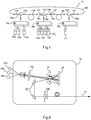
- the figure 1 schematically represents an optical ring communication network 10 according to one embodiment of the invention, for example on board an aircraft.
- the optical network 10 is intended to allow transmission of computer data between equipment 12a-12h.
- the communication network comprises a set of branch boxes 14a-14h, each connected directly to two other branch boxes by optical fibers 16a-16h multimode and bidirectional so as to form a ring.
- the figure 1 is not to scale and the junction boxes may be further apart and distributed differently on the ring.
- Each junction box is further adapted to be connected to a multiplexer / demultiplexer by a multimode and bidirectional optical fiber.
- each junction box may or may not be connected to a multiplexer / demultiplexers: the junction boxes connected to a multiplexer / demultiplexer, here the junction boxes 14b, 14d, 14g, allow connection to the network optical devices connected to the multiplexer / demultiplexer, and the branching boxes not connected to a multiplexer / demultiplexer make it possible to offer a connection socket in the event of the need to add equipment to the network via a multiplexer / demultiplexer.
- the junction boxes can thus be distributed throughout the aircraft in anticipation of new equipment to be added in the future.
- the branch box 14b is connected to a multiplexer / demultiplexer 18a allowing the connection of the devices 12a, 12b, 12c to the network
- the branch box 14d is connected to a multiplexer / demultiplexer 18b allowing the connection of the devices 12d, 12e, 12f, 12g to the network
- the branch box 14g is connected to a multiplexer / demultiplexer 18c allowing the connection of the equipment 12h to the network.
- the optical network can allow to measure the angular speed of the aircraft in the plane in which the ring extends.
- the figure 2 schematically represents a multiplexer / demultiplexer 18 of an optical network according to one embodiment of the invention.
- the operation of the multiplexer / demultiplexer 18 is explained here in its functioning as a multiplexer.
- the demultiplexer function is analogous in the reverse direction.
- the multiplexer / demultiplexer 18 receives optical signals originating from the equipment and intended to be transmitted to the optical network, here three equipment signals 20a, 20b, 20c, which may have an equal or different frequency. If the equipment does not transmit optical signals but for example electrical signals, the multiplexer / demultiplexer can include means for converting electrical signals into optical signals. By passing the three equipment signals 20a, 20b, 20c through a plurality of passive optical elements, the equipment signals will be combined to form a single optical signal 21 in which each equipment signal has been modulated so to present a particular mode of propagation.
- the multiplexer / demultiplexer 18 carries out to do this a succession of several optical Fourier transforms via the passive optical elements, for example in this embodiment a mirror 22 and a phase network 24, the equipment signals effecting several reflections between the phase network 24 and mirror 22 until segregation by mode and combination.
- the passive optical elements also include a collimating lens 26a and focal length lenses 26b, as well as return mirrors 28.
- the demultiplexer function works in the opposite direction, that is to say that a single optical signal enters the multiplexer / demultiplexer 18 and is decomposed into several output signals transmitted to each equipment, using the same components.
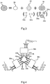
- the figure 3 schematically shows the different modes that can be transported in a single multimode optical fiber of an optical communication network according to one embodiment of the invention.
- Reference 21 represents the shape of the optical signal as propagated in a multimode optical fiber according to a cross section of said fiber.
- the first mode 30 is a TEM 00 type mode
- the second mode 32 is a TEM 01 type mode (or a combination of two TEM 01 type modes 32a and 32b)
- the third mode 34 is a TEM 02 mode (or a combination of three TEM 02 type modes 34a, 34b and 34c).
- Reference 21 thus represents the sum of the groups of modes 30, 32 and 34, themselves made up of modes 30, 32a and 32b, 34a and 34b and 34c.
- the described embodiment of the invention is only indicative as a solution for combining three equipment signals. According to other embodiments, more modes can be used to allow the combination of more than three equipment signals, depending on the needs of the network and the number of connected equipment. In addition, the types of modes used may be different.
- the figure 4 schematically represents a junction box of an optical communication network according to one embodiment of the invention.
- the junction box comprises three separators, a first separator 36a, a second separator 36b and a third separator 36c, as well as a right prism 38 having an equilateral triangle as its base.
- Each splitter 36a, 36b, 36c is connected to a multimode optical fiber, and receives an optical signal coming either from another neighboring junction box in the ring, or from a multiplexer / demultiplexer.
- the splitters 36a, 36b receive, for example, optical signals from other junction boxes and the splitter 36b can receive an optical signal from a multiplexer / demultiplexer.
- the splitters make it possible to divide the optical signals in order to transmit them to the other two splitters, as well as to receive the optical signals coming from the other two splitters.
- the first splitter 36a for example divides the signal received into two identical optical signals, forming optical beams, a first optical beam 40a and a second optical beam 42a.
- the first optical beam 40a is directed towards one face of the prism and is reflected towards the second splitter 36b.
- the second optical beam 42a is directed towards one face of the prism 38 and is reflected towards the third splitter 36c.
- the first splitter receives an optical beam 40b coming from the second splitter 36b and reflected by the prism 38 and an optical beam 42c coming from the third splitter 36c and reflected by the prism 38.
- the second splitter 36b sends a beam 44b optical to the third splitter 36c and receives an optical beam 44c from the third splitter 36c.
- the splitters can be configured so that the first splitter 36a and the third splitter 36c send / receive only the optical beams 42a and 42c.
- each splitter Upon reception of the optical beams from the other splitters, each splitter combines these optical beams and transmits the resulting optical signal to the optical fiber to which it is connected.
- the invention is not limited to the only embodiments described.
- other types of optical networks are possible.
- the configurations of the passive optical elements of multiplexers / demultiplexers as well as of the junction boxes can be modified as long as the function performed is identical and that only passive optical elements are used, because they allow the conservation of the modes of the optical signals. .
Description
L'invention concerne un réseau optique embarqué de type réseau en anneau. En particulier, l'invention concerne un réseau de communication optique pouvant être embarqué dans un aéronef afin de permettre la communication d'équipements de l'aéronef entre eux.The invention relates to an on-board optical network of the ring network type. In particular, the invention relates to an optical communication network that can be on board an aircraft in order to allow communication of equipment of the aircraft with one another.
L'état de la technique comprend notamment les documents
Afin de relier des équipements d'un aéronef entre eux à des fins de communication, les aéronefs sont équipés de différents câblages formant un réseau dont l'installation et la maintenance peuvent être complexes. En outre, ce câblage présente un coût important, d'une part en termes de prix des câbles mais aussi en termes de poids entraînant une hausse de la consommation de carburant durant le vol.In order to connect the items of equipment of an aircraft to one another for communication purposes, the aircraft are equipped with different cabling forming a network, the installation and maintenance of which can be complex. In addition, this wiring has a significant cost, on the one hand in terms of the price of the cables but also in terms of weight, resulting in an increase in fuel consumption during the flight.
De plus, les réseaux actuels utilisent généralement des câbles en cuivre formant un mélange de réseau en étoile et en anneau, de type « Switched Ethernet » AFDX. Les câbles utilisent un support en cuivre de deux paires torsadées et redondées.In addition, current networks generally use copper cables forming a mixture of star and ring networks, of the AFDX “Switched Ethernet” type. The cables use a copper backing of two redundant twisted pairs.
Ce type de réseau à câbles en cuivre possède plusieurs inconvénients : les câbles métalliques posent des problématiques de perturbations électromagnétiques (compatibilité électromagnétique, induction de courant, etc.), le réseau est peu adaptable aux modifications (ajout de nouvel équipement par exemple), le réseau a un débit limité à quelques dizaines de Mb/sec (essentiellement dû à l'aspect déterministe du protocole TCP), et le poids des câbles est élevé (environ 32kg/km, un avion pouvant comprendre par exemple plusieurs centaines de kilomètre de câbles). À tous ces inconvénients s'ajoute en outre un coût élevé de maintenance et de modification.This type of copper cable network has several drawbacks: metal cables pose problems of electromagnetic interference (electromagnetic compatibility, current induction, etc.), the network is not very adaptable to modifications (addition of new equipment for example), the network has a speed limited to a few tens of Mb / sec (mainly due to the deterministic aspect of the TCP protocol), and the weight of the cables is high (around 32 kg / km, an airplane can include for example several hundred kilometers of cables ). In addition to all these drawbacks, there is also a high cost of maintenance and modification.
Une solution proposée à au moins une partie de ces inconvénients a été de remplacer les câbles en cuivre par des fibres optiques. Toutefois, le réseau obtenu r ne permet pas une grande adaptabilité.One solution proposed to at least some of these drawbacks has been to replace copper cables with optical fibers. However, the network obtained r does not allow great adaptability.
L'invention vise à pallier au moins certains des inconvénients des réseaux de communication connus.The invention aims to overcome at least some of the drawbacks of known communication networks.
En particulier, l'invention vise à fournir, dans au moins un mode de réalisation de l'invention, un réseau de communication permettant d'améliorer les communications entre des équipements d'un aéronef.In particular, the invention aims to provide, in at least one embodiment of the invention, a communication network making it possible to improve communications between equipment items of an aircraft.
L'invention vise aussi à fournir, dans au moins un mode de réalisation, un réseau de communication permettant une augmentation du débit des échanges de données.The invention also aims to provide, in at least one embodiment, a communication network allowing an increase in the throughput of data exchanges.
L'invention vise aussi à fournir, dans au moins un mode de réalisation de l'invention, un réseau de communication permettant la connexion ou la déconnexion facile d'équipements.The invention also aims to provide, in at least one embodiment of the invention, a communication network allowing easy connection or disconnection of equipment.
L'invention vise aussi à fournir, dans au moins un mode de réalisation de l'invention, un réseau de communication offrant une meilleure sécurité des transmissions de données.The invention also aims to provide, in at least one embodiment of the invention, a communication network offering better security of data transmissions.
L'invention vise aussi à fournir, dans au moins un mode de réalisation de l'invention, un réseau de communication permettant une redondance en cas de dégradation d'une partie du réseau.The invention also aims to provide, in at least one embodiment of the invention, a communication network allowing redundancy in the event of degradation of a part of the network.
Pour ce faire, l'invention concerne un réseau de communication optique embarqué en anneau adapté pour permettre une transmission de données entre des équipements, comprenant :
- un ensemble de boîtiers de dérivation reliés chacun d'une part directement à deux autres boîtiers de dérivation par des fibres optiques multimodes et bidirectionnelles de façon à former un anneau, et adaptés pour être reliés d'autre part à au moins un multiplexeur/démultiplexeur par des fibres optiques multimodes et bidirectionnelles,
- chaque fibre optique est adaptée pour permettre le transport de signaux optiques d'au moins trois modes différents,
- chaque multiplexeur/démultiplexeur comprend une pluralité d'éléments optiques passifs et permet de transmettre au moins trois signaux d'équipements provenant des équipements via un multiplexage modal dans une fibre optique ou de séparer les modes d'un signal optique provenant de la fibre optique vers au moins trois signaux d'équipements,
- les boîtiers de dérivation comprennent chacun trois séparateurs auxquels sont connectées les fibres optiques et chacun dirigés vers au moins un prisme, lesdits séparateurs et ledit prisme étant configurés pour diriger un signal optique provenant d'une fibre optique et entrant dans un séparateur vers les deux autres séparateurs et pour que chaque séparateur reçoive les signaux optiques provenant des deux autres séparateurs et envoie ces signaux à la fibre optique à laquelle il est connecté.
- a set of junction boxes each connected on the one hand directly to two other junction boxes by multimode and bidirectional optical fibers so as to form a ring, and adapted to be connected on the other hand to at least one multiplexer / demultiplexer by multimode and bidirectional optical fibers,
- each optical fiber is adapted to allow the transport of optical signals of at least three different modes,
- each multiplexer / demultiplexer comprises a plurality of passive optical elements and makes it possible to transmit at least three signals equipment from equipment via modal multiplexing in an optical fiber or to separate the modes of an optical signal from the optical fiber to at least three equipment signals,
- the junction boxes each include three splitters to which the optical fibers are connected and each directed towards at least one prism, said splitters and said prism being configured to direct an optical signal coming from an optical fiber and entering one splitter to the other two splitters and for each splitter to receive optical signals from the other two splitters and send these signals to the optical fiber to which it is connected.
Un réseau de communication optique selon l'invention permet donc une communication entre différents équipements à un débit élevé (jusqu'à plusieurs dizaines de Gb/seconde sur plus d'une centaine de mètres): le multiplexage par modes de propagation permet de s'ajouter aux multiplexages utilisés couramment (notamment multiplexage en longueur d'onde et multiplexage temporel) afin d'augmenter le nombre d'équipements pouvant communiquer simultanément sur le réseau. En outre, le multiplexage par mode permet, par maîtrise d'injection et de propagation des modes des signaux optiques, de s'affranchir de la dispersion modale.An optical communication network according to the invention therefore allows communication between different equipment at a high rate (up to several tens of Gb / second over more than a hundred meters): multiplexing by propagation modes makes it possible to s' add to commonly used multiplexing (in particular wavelength multiplexing and time multiplexing) in order to increase the number of devices that can communicate simultaneously on the network. In addition, mode multiplexing makes it possible, by controlling the injection and propagation of the modes of the optical signals, to overcome modal dispersion.
Les séparateurs et le prisme des boîtiers de dérivation sont des composants passifs, qui permettent de transmettre les signaux optiques sans perte des modes du signal optique transmis. Les séparateurs permettent de former, à partir d'un signal optique reçu et grâce à des éléments optiques passifs, deux signaux optiques identiques qui sont dirigés vers des parties différentes du prisme. Par réflexion ou réfraction, le prisme dirige un premier de ces deux signaux optiques vers un premier des autres séparateurs et un deuxième de ces deux signaux vers un deuxième séparateur. De même, par fonctionnement inverse, chaque séparateur reçoit deux signaux optiques provenant des deux autres séparateurs, permettant ainsi un fonctionnement bidirectionnel de la transmission entre chaque séparateur deux à deux.The splitters and the prism of the junction boxes are passive components, which allow optical signals to be transmitted without losing the modes of the transmitted optical signal. The separators make it possible to form, from a received optical signal and by means of passive optical elements, two identical optical signals which are directed towards different parts of the prism. By reflection or refraction, the prism directs a first of these two optical signals towards a first of the other separators and a second of these two signals towards a second separator. Likewise, by reverse operation, each separator receives two optical signals originating from the other two separators, thus allowing bidirectional operation of the transmission between each separator two by two.
Le fonctionnement passif des boîtiers de dérivation leur permet aussi de fonctionner sans la présence d'un multiplexeur/démultiplexeur connecté à un des séparateurs. Dans ce cas, le boîtier de dérivation se comporte comme une prise dans le réseau, transmettant les signaux optiques d'un boîtier de dérivation voisin vers le boîtier de dérivation suivant dans l'anneau, et disponible pour pouvoir raccorder de nouveaux équipements au réseau. Ainsi, les boitiers de dérivations peuvent être répartis dans l'infrastructure dans laquelle le réseau est déployé, par exemple un aéronef, en prévision de nouveaux équipements à ajouter dans le futur. De même, lorsque qu'un équipement ou un ensemble d'équipements doit être retiré du réseau, le multiplexeur/démultiplexeur associé peut être déconnecté du boîtier de dérivation, sans nécessiter de reconfiguration du réseau pour son bon fonctionnement.The passive operation of the junction boxes also allows them to operate without the presence of a multiplexer / demultiplexer connected to one of the splitters. In this case, the junction box behaves like a socket in the network, transmitting optical signals from a neighboring junction box to the next junction box in the ring, and available to be able to connect new equipment to the network. Thus, the junction boxes can be distributed in the infrastructure in which the network is deployed, for example an aircraft, in anticipation of new equipment to be added in the future. Likewise, when an item of equipment or a set of items of equipment must be removed from the network, the associated multiplexer / demultiplexer can be disconnected from the junction box, without requiring network reconfiguration for its correct operation.
Le multiplexage par mode permet aussi d'améliorer la sécurité de la transmission des données, car l'opération de séparation des modes (démultiplexage) peut être effectuée uniquement par les démultiplexeurs modaux: une interception de données au niveau de la fibre optique, par exemple en dénudant et courbant cette fibre optique, ne permettra pas d'obtenir un signal optique lisible.Mode multiplexing also improves the security of data transmission, since the mode separation operation (demultiplexing) can be performed only by modal demultiplexers: data interception at the optical fiber level, for example by stripping and bending this optical fiber, it will not make it possible to obtain a readable optical signal.
En outre, du fait de la configuration du réseau en anneau et du fait que chaque fibre optique permette la transmission des signaux optiques dans les deux sens (fibre bidirectionnelle), le réseau optique présente une redondance permettant, en cas de défaillance du réseau, de permettre à tous les équipements de rester connectés.In addition, due to the configuration of the ring network and the fact that each optical fiber allows the transmission of optical signals in both directions (bidirectional fiber), the optical network has redundancy allowing, in the event of network failure, to allow all equipment to stay connected.
Enfin, un réseau de communication selon l'invention permet de transmettre dans un même canal optique multiplexé des informations indépendantes et ségréguées selon leurs criticités ou leurs types de façon optique (ou modal), sans interférence d'une mode optique à un autre.Finally, a communication network according to the invention makes it possible to transmit, in the same multiplexed optical channel, independent information segregated according to their criticalities or their types in an optical (or modal) manner, without interference from one optical mode to another.
Avantageusement et selon l'invention, le prisme est un prisme droit ayant comme base un triangle équilatéral.Advantageously and according to the invention, the prism is a right prism having an equilateral triangle as its base.
Selon cet aspect de l'invention, le séparateur dirige un premier signal optique vers une première face latérale (rectangulaire) du prisme. Par réflexion sur cette face, ce premier signal optique est dirigé vers un premier des autres séparateurs. De même, le séparateur dirige un deuxième signal optique vers une deuxième face latérale du prisme et par réflexion sur cette face, ce deuxième signal optique est dirigé vers un deuxième des autres séparateurs. Le prisme joue ainsi le rôle d'un miroir multifacettes. Les angles d'incidences et l'indice de réfraction du prisme sont configurés pour permettre ces réflexions.According to this aspect of the invention, the splitter directs a first optical signal towards a first lateral (rectangular) face of the prism. By reflection on this face, this first optical signal is directed towards a first of the other separators. Likewise, the splitter directs a second optical signal to a second lateral face of the prism and by reflection on this face, this second optical signal is directed towards a second of the other separators. The prism thus plays the role of a multifaceted mirror. The angles of incidence and the refractive index of the prism are configured to allow these reflections.
Avantageusement et selon l'invention, les fibres optiques multimode ont un diamètre de cœur supérieur à 50 µm.Advantageously and according to the invention, multimode optical fibers have a core diameter greater than 50 μm.
Selon cet aspect de l'invention, la fibre multimode a un diamètre de cœur suffisamment élevé pour permettre la propagation des signaux de modes différents dans la fibre.According to this aspect of the invention, the multimode fiber has a sufficiently large core diameter to allow the propagation of signals of different modes in the fiber.
Avantageusement et selon l'invention, les boîtiers de dérivation et les fibres optiques formant l'anneau sont disposés dans un même plan, et le réseau optique comprend un capteur permettant de mesurer le temps de propagation de deux signaux optiques dans l'anneau, les deux signaux optiques parcourant l'anneau dans un sens de propagation opposé.Advantageously and according to the invention, the junction boxes and the optical fibers forming the ring are arranged in the same plane, and the optical network comprises a sensor making it possible to measure the propagation time of two optical signals in the ring, the two optical signals traveling through the ring in an opposite direction of propagation.
Selon cet aspect de l'invention, le réseau optique en anneau permet de former un gyromètre à effet Sagnac, permettant la mesure de la vitesse angulaire d'un moyen de transport dans lequel le réseau optique est embarqué, selon le plan dans lequel s'étendent les boîtiers de dérivation et les fibres optiques formant l'anneau. Cet aspect de l'invention est particulièrement utile dans un aéronef, et selon la configuration de l'anneau, permet de mesurer la vitesse angulaire selon le plan dans lequel s'étend l'anneau (par exemple mesure du roulis, tangage ou lacet de l'aéronef).According to this aspect of the invention, the optical ring network makes it possible to form a Sagnac effect gyrometer, allowing the measurement of the angular speed of a means of transport in which the optical network is on board, according to the plane in which s' extend the junction boxes and optical fibers forming the ring. This aspect of the invention is particularly useful in an aircraft, and depending on the configuration of the ring, makes it possible to measure the angular speed according to the plane in which the ring extends (for example measurement of the roll, pitch or yaw of the aircraft).
L'invention concerne également un aéronef comprenant une pluralité d'équipements, caractérisé entre ce qu'il comprend un réseau optique selon l'invention pour la transmission de données entre lesdits équipements.The invention also relates to an aircraft comprising a plurality of items of equipment, characterized in that it comprises an optical network according to the invention for the transmission of data between said items of equipment.
Les équipements de l'aéronef peuvent ainsi transmettre des données par le réseau optique y compris si ceux-ci émettent leurs signaux aux mêmes longueurs d'onde.The equipment of the aircraft can thus transmit data via the optical network, even if the latter emit their signals at the same wavelengths.
L'invention concerne également un réseau de communication optique et un aéronef caractérisés en combinaison par tout ou partie des caractéristiques mentionnées ci-dessus ou ci-après.The invention also relates to an optical communication network and an aircraft characterized in combination by all or some of the characteristics mentioned above or below.
D'autres buts, caractéristiques et avantages de l'invention apparaîtront à la lecture de la description suivante donnée à titre uniquement non limitatif et qui se réfère aux figures annexées dans lesquelles :
- la
figure 1 est une vue schématique d'un réseau de communication optique selon un mode de réalisation de l'invention, - la
figure 2 est une vue schématique d'un multiplexeur d'un réseau de communication optique selon un mode de réalisation de l'invention, - la
figure 3 est une vue schématique de différents modes pouvant être transporté dans une même fibre optique multimode d'un réseau de communication optique selon un mode de réalisation de l'invention, - la
figure 4 est une vue schématique d'un boîtier de dérivation d'un réseau de communication optique selon un mode de réalisation de l'invention,
- the
figure 1 is a schematic view of an optical communication network according to one embodiment of the invention, - the
figure 2 is a schematic view of a multiplexer of an optical communication network according to one embodiment of the invention, - the
figure 3 is a schematic view of different modes that can be transported in the same multimode optical fiber of an optical communication network according to one embodiment of the invention, - the
figure 4 is a schematic view of a junction box of an optical communication network according to one embodiment of the invention,
Les réalisations suivantes sont des exemples. Bien que la description se réfère à un ou plusieurs modes de réalisation, ceci ne signifie pas nécessairement que chaque référence concerne le même mode de réalisation, ou que les caractéristiques s'appliquent seulement à un seul mode de réalisation. De simples caractéristiques de différents modes de réalisation peuvent également être combinées pour fournir d'autres réalisations. Sur les figures, les échelles et les proportions ne sont pas strictement respectées et ce, à des fins d'illustration et de clarté.The following embodiments are examples. Although the description refers to one or more embodiments, this does not necessarily mean that each reference relates to the same embodiment, or that the characteristics apply only to one embodiment. Simple features of different embodiments can also be combined to provide other embodiments. In the figures, the scales and proportions are not strictly observed, for the purposes of illustration and clarity.
La
Chaque boîtier de dérivation est en outre adapté pour être relié à un multiplexeur/démultiplexeur par une fibre optique multimode et bidirectionnelles. En configuration normale du réseau, chaque boîtier de dérivation peut être ou ne pas être relié à un multiplexeur/démultiplexeurs : les boîtiers de dérivation reliés à un multiplexeur/démultiplexeur, ici les boîtiers 14b, 14d, 14g de dérivation, permettent la connexion au réseau optique des équipements reliés au multiplexeur/démultiplexeur, et les boîtiers de dérivation non reliés à un multiplexeur/démultiplexeur permettent de proposer une prise de connexion en cas de nécessité d'ajout d'équipements au réseau via un multiplexeur/démultiplexeur. En pratique, les boîtiers de dérivation peuvent ainsi être répartis dans l'aéronef en prévision de nouveaux équipements à ajouter dans le futur.Each junction box is further adapted to be connected to a multiplexer / demultiplexer by a multimode and bidirectional optical fiber. In normal network configuration, each junction box may or may not be connected to a multiplexer / demultiplexers: the junction boxes connected to a multiplexer / demultiplexer, here the
Dans ce mode de réalisation, le boîtier 14b de dérivation est relié à un multiplexeur/démultiplexeur 18a permettant la connexion des équipements 12a, 12b, 12c au réseau, le boîtier 14d de dérivation est relié à un multiplexeur/démultiplexeur 18b permettant la connexion des équipements 12d, 12e, 12f, 12g au réseau, et le boîtier 14g de dérivation est relié à un multiplexeur/démultiplexeur 18c permettant la connexion de l'équipement 12h au réseau.In this embodiment, the
En mesurant la différence du temps de propagation dans l'anneau d'un signal optique se propageant dans les fibres 16a-16h optiques multimodes durant un tour complet de l'anneau dans un sens et dans le sens inverse, le réseau 10 optique peut permettre de mesurer la vitesse angulaire de l'aéronef dans le plan dans lequel s'étend l'anneau.By measuring the difference in the propagation time in the ring of an optical signal propagating in the multimode
La
Le fonctionnement du multiplexeur/démultiplexeur 18 est expliqué ici dans son fonctionnement comme multiplexeur. La fonction démultiplexeur est analogue dans le sens inverse.The operation of the multiplexer /
Le multiplexeur/démultiplexeur 18 reçoit des signaux optiques provenant des équipements et destiné à être transmis au réseau optique, ici trois signaux 20a, 20b, 20c d'équipements, pouvant avoir une fréquence égale ou différente. Si les équipements ne transmettent pas de signaux optiques mais des signaux par exemple électriques, le multiplexeur/démultiplexeur peut comprendre des moyens de conversion des signaux électriques en signaux optiques. Par le passage des trois signaux 20a, 20b, 20c d'équipements dans une pluralité d'éléments optiques passifs, les signaux d'équipements vont être combinés pour former un signal 21 optique unique dans lequel chaque signal d'équipement a été modulé de sorte à présenter un mode particulier de propagation. Le multiplexeur/démultiplexeur 18 effectue pour ce faire une succession de plusieurs transformées de Fourier optiques via les éléments optiques passifs, par exemple dans ce mode de réalisation un miroir 22 et un réseau 24 de phase, les signaux d'équipements effectuant plusieurs réflexions entre le réseau 24 de phase et le miroir 22 jusqu'à ségrégation par mode et combinaison. Les éléments optiques passifs comprennent aussi une lentille 26a de collimation et des lentilles 26b de focale, ainsi que des miroirs 28 de renvoi.The multiplexer /
Comme expliqué précédemment, la fonction démultiplexeur fonctionne dans le sens inverse, c'est-à-dire qu'un signal optique unique entre dans le multiplexeur/démultiplexeur 18 et est décomposé en plusieurs signaux de sortie transmis à chaque équipement, en utilisant les mêmes composants.As explained previously, the demultiplexer function works in the opposite direction, that is to say that a single optical signal enters the multiplexer /
La ségrégation des signaux par mode à l'issu de ce multiplexage est décrite sur la
La
La référence 21 représente la forme du signal optique tel que propagé dans une fibre optique multimode selon une coupe transversale de ladite fibre. Le signal 21 optique, par exemple lors de la combinaison des trois signaux 20a, 20b, 20c tel que décrit précédemment, peut être considéré comme la somme des trois modes utilisés pour la propagation de ces signaux d'équipements dans le signal optique unique. Dans ce mode de réalisation, le premier mode 30 est un mode de type TEM00, le deuxième mode 32 est un mode de type TEM01 (ou une combinaison de deux modes 32a et 32b de type TEM01), le troisième mode 34 est un mode TEM02 (ou une combinaison de trois modes 34a, 34b et 34c de type TEM02). La référence 21 représente ainsi la somme des groupes de modes 30, 32 et 34, eux-mêmes composés des modes 30, 32a et 32b, 34a et 34b et 34c.
Le mode de réalisation de l'invention décrit est uniquement à titre indicatif comme solution pour combiner trois signaux d'équipements. Selon d'autres modes de réalisation, davantage de modes peuvent être utilisés pour permettre la combinaison de plus de trois signaux d'équipements, selon les besoins du réseau et le nombre d'équipements connectés. En outre, les types de modes utilisés peuvent être différents.The described embodiment of the invention is only indicative as a solution for combining three equipment signals. According to other embodiments, more modes can be used to allow the combination of more than three equipment signals, depending on the needs of the network and the number of connected equipment. In addition, the types of modes used may be different.
La
Le boîtier de dérivation comprend trois séparateurs, un premier séparateur 36a, un deuxième séparateur 36b et un troisième séparateurs 36c, ainsi qu'un prisme 38 droit ayant comme base un triangle équilatéral. Chaque séparateur 36a, 36b, 36c est relié à une fibre optique multimode, et reçoit un signal optique provenant soit d'une autre boite de dérivation voisine dans l'anneau, soit d'un multiplexeur/démultiplexeur. Dans le mode de réalisation illustré, les séparateurs 36a, 36b reçoivent par exemple des signaux optiques provenant d'autres boîtiers de dérivation et le séparateur 36b peut recevoir un signal optique provenant d'un multiplexeur/démultiplexeur.The junction box comprises three separators, a
Les séparateurs permettent de diviser les signaux optiques pour les transmettre aux deux autres séparateurs, ainsi que de recevoir les signaux optiques provenant des deux autres séparateurs. Pour ce faire, le premier séparateur 36a divise par exemple le signal reçu en deux signaux optiques identiques, formant des faisceaux optiques, un premier faisceau 40a optique et un deuxième faisceau 42a optique. Le premier faisceau 40a optique est dirigé vers une face du prisme et est réfléchi vers le deuxième séparateur 36b. Le deuxième faisceau 42a optique est dirigé vers une face du prisme 38 et est réfléchi vers le troisième séparateur 36c.The splitters make it possible to divide the optical signals in order to transmit them to the other two splitters, as well as to receive the optical signals coming from the other two splitters. To do this, the
À l'inverse, le premier séparateur reçoit un faisceau 40b optique provenant du deuxième séparateur 36b et réfléchi par le prisme 38 et un faisceau 42c optique provenant du troisième séparateur 36c et réfléchi par le prisme 38. Enfin, le deuxième séparateur 36b envoie un faisceau 44b optique vers le troisième séparateur 36c et reçoit un faisceau 44c optique du troisième séparateur 36c.Conversely, the first splitter receives an
Dans le cas où le deuxième séparateur 36b ne serait pas connecté à un multiplexeur/démultiplexeur (le boîtier de dérivation est ainsi disponible pour connecter de nouveaux équipements), les séparateurs peuvent être configurés pour que le premier séparateur 36a et le troisième séparateur 36c envoient/reçoivent uniquement les faisceaux 42a et 42c optiques.In the event that the
À la réception des faisceaux optiques provenant des autres séparateurs, chaque séparateur combine ces faisceaux optiques et transmet le signal optique obtenu vers la fibre optique à laquelle il est connecté.Upon reception of the optical beams from the other splitters, each splitter combines these optical beams and transmits the resulting optical signal to the optical fiber to which it is connected.
L'invention ne se limite pas aux seuls modes de réalisation décrits. En particulier, d'autres types de réseaux optiques sont possibles. Par exemple, les configurations des éléments optiques passifs des multiplexeurs/démultiplexeurs ainsi que des boîtiers de dérivations peuvent être modifiés du moment que la fonction réalisée est identique et que seuls des éléments optiques passifs sont utilisés, car ils permettent la conservation des modes des signaux optiques.The invention is not limited to the only embodiments described. In particular, other types of optical networks are possible. For example, the configurations of the passive optical elements of multiplexers / demultiplexers as well as of the junction boxes can be modified as long as the function performed is identical and that only passive optical elements are used, because they allow the conservation of the modes of the optical signals. .
Claims (5)
- Embedded optical ring communication network suitable to enable a transmission of data between equipment (12a-12h), comprising:- an assembly of distribution boxes (14a-14h) each connected, on the one hand, directly to two other distribution boxes (14a-14h) by multimode and bidirectional optical fibers (16a-16h) so as to form a ring, and suitable for being connected, on the other hand, to at least one multiplexer/demultiplexer (18a, 18b, 18c) by multimode and bidirectional optical fibers,- each optical fiber (16a-16h) is suitable to enable the transport of optical signals of at least three different modes (32, 32, 34),- each multiplexer/demultiplexer (18a, 18b, 18c) comprises a plurality of passive optical elements and enables to transmit at least three equipment signals coming from the equipment (12a-12h) via a modal multiplexing in an optical fiber or to separate the modes of an optical signal coming from the optical fibers towards at least three equipment signals,characterised in that:- the distribution boxes (14a-14h) each comprise three separators (36a, 36b, 36c), to which are connected the optical fibers and each directed towards at least a prism (38), said separators (36a, 36b, 36c) and said prism (38) being configured to direct an optical signal coming from an optical fiber and entering into a separator towards the two other separators and so that each separator receives the optical signals coming from the two other separators and sends these signals to the optical fiber to which it is connected.
- Optical network according to claim 1, characterised in that the prism (38) is a straight prism having an equilateral triangle as base.
- Optical network according to one of claims 1 or 2, characterised in that the multimode optical fibers (16a-16h) have a core diameter greater than 50 µm.
- Optical network according to one of claims 1 to 3, characterised in that the distribution boxes (14a-14h) and the optical fibers (16a-16h) forming the ring are arranged in a same plane, and in that the optical network comprises a sensor enabling to measure the propagation time of two optical signals in the ring, the two optical signals traveling the ring in an opposite propagation direction.
- Aircraft comprising a plurality of equipment (12a-12h), characterised in that it comprises an optical network (10) according to one of claims 1 to 4, for the transmission of data between said equipment (12a-12h).
Applications Claiming Priority (2)
| Application Number | Priority Date | Filing Date | Title |
|---|---|---|---|
| FR1662226A FR3060248B1 (en) | 2016-12-09 | 2016-12-09 | OPTICAL RING OPERATED COMMUNICATION NETWORK FOR AIRCRAFT |
| PCT/FR2017/053419 WO2018104665A1 (en) | 2016-12-09 | 2017-12-06 | Embedded optical ring communication network for aircraft |
Publications (2)
| Publication Number | Publication Date |
|---|---|
| EP3552324A1 EP3552324A1 (en) | 2019-10-16 |
| EP3552324B1 true EP3552324B1 (en) | 2021-02-24 |
Family
ID=58992920
Family Applications (1)
| Application Number | Title | Priority Date | Filing Date |
|---|---|---|---|
| EP17821686.7A Active EP3552324B1 (en) | 2016-12-09 | 2017-12-06 | Embedded optical ring communication network for aircraft |
Country Status (5)
| Country | Link |
|---|---|
| US (1) | US10587342B2 (en) |
| EP (1) | EP3552324B1 (en) |
| CN (1) | CN110050418B (en) |
| FR (1) | FR3060248B1 (en) |
| WO (1) | WO2018104665A1 (en) |
Families Citing this family (2)
| Publication number | Priority date | Publication date | Assignee | Title |
|---|---|---|---|---|
| FR3129002A1 (en) | 2021-11-05 | 2023-05-12 | Safran Electrical & Power | Connection device by transmission channel reassignment to an on-board multiplexed passive fiber communication network for an aircraft |
| FR3129221A1 (en) | 2021-11-15 | 2023-05-19 | Safran Electrical & Power | Hybrid optical multiplexer, associated hybrid optical demultiplexer and associated on-board optical communication network |
Family Cites Families (64)
| Publication number | Priority date | Publication date | Assignee | Title |
|---|---|---|---|---|
| US3840738A (en) * | 1973-05-09 | 1974-10-08 | Bell Telephone Labor Inc | Optical communications system with means for minimizing material dispersion |
| US4027945A (en) * | 1976-03-04 | 1977-06-07 | The United States Of America As Represented By The Secretary Of The Navy | Optical sliprings |
| US4278327A (en) * | 1979-11-26 | 1981-07-14 | Sperry Corporation | Liquid crystal matrices |
| US4366565A (en) * | 1980-07-29 | 1982-12-28 | Herskowitz Gerald J | Local area network optical fiber data communication |
| JPS57204507A (en) * | 1981-06-12 | 1982-12-15 | Nec Corp | Interference film type optical multiplexer and demultiplexer |
| US4431258A (en) * | 1981-12-15 | 1984-02-14 | Gte Laboratories Incorporated | Optical fiber transmission system and dichroic beam splitter therefor |
| US4516837A (en) * | 1983-02-22 | 1985-05-14 | Sperry Corporation | Electro-optical switch for unpolarized optical signals |
| FR2553243B1 (en) * | 1983-10-11 | 1990-03-30 | Lignes Telegraph Telephon | WAVELENGTH OPTICAL WAVELENGTH MULTIPLEXER-DEMULTIPLEXER FOR BIDIRECTIONAL LINK |
| US5271076A (en) * | 1992-10-05 | 1993-12-14 | The United States Of America As Represented By The Secretary Of The Navy | Method providing optimum optical trains alignment in a passive multi-channel fiber optic rotary joint |
| WO1999035522A1 (en) * | 1998-01-05 | 1999-07-15 | Corning Incorporated | Add/drop optical multiplexing device |
| US6014244A (en) * | 1998-06-18 | 2000-01-11 | Hewlett-Packard Company | Multi-port optical circulator utilizing imaging lens and correction optical element |
| US6253007B1 (en) * | 1998-07-08 | 2001-06-26 | Optical Switch Corporation | Method and apparatus for connecting optical fibers |
| JP3586586B2 (en) * | 1999-05-24 | 2004-11-10 | 日本電気株式会社 | Light wave ring system |
| US6363186B1 (en) * | 2000-02-29 | 2002-03-26 | Nec Research Institute, Inc. | X-cube integrated solid optics component |
| CA2409216A1 (en) * | 2000-05-16 | 2001-11-22 | Photuris, Inc. | A reconfigurable optical switch |
| US6941072B2 (en) * | 2000-10-17 | 2005-09-06 | Jds Uniphase Corporation | Compact optical multiplexer/demultiplexer |
| EP1334390B1 (en) * | 2000-11-01 | 2008-07-30 | Intel Corporation | System and method for collimating and redirecting beams |
| JP2002169022A (en) * | 2000-12-04 | 2002-06-14 | Nippon Sheet Glass Co Ltd | Optical element, spectroscopic device and integrated optical device using the same |
| US7042631B2 (en) * | 2001-01-04 | 2006-05-09 | Coherent Technologies, Inc. | Power scalable optical systems for generating, transporting, and delivering high power, high quality, laser beams |
| US6597829B2 (en) * | 2001-04-27 | 2003-07-22 | Robert H. Cormack | 1xN optical fiber switch |
| US7496257B2 (en) * | 2001-07-03 | 2009-02-24 | Brown University Research Foundation | Method and apparatus for detecting multiple optical wavelengths |
| US6781693B2 (en) * | 2001-07-27 | 2004-08-24 | Gigabit Optics Corporation | System and method for optical multiplexing and/or demultiplexing |
| US6571033B2 (en) * | 2001-09-28 | 2003-05-27 | Corning Incorporated | Optical signal device |
| JP3517406B2 (en) * | 2001-10-10 | 2004-04-12 | サンテック株式会社 | Wavelength variable multiplexer / demultiplexer and wavelength routing device |
| US6775432B2 (en) * | 2001-10-19 | 2004-08-10 | Santanu Basu | Method and apparatus for optical wavelength demultiplexing, multiplexing and routing |
| US6751366B2 (en) * | 2002-02-12 | 2004-06-15 | Oplink Communications, Inc. | Multi-port circulator |
| US7606494B1 (en) * | 2002-06-04 | 2009-10-20 | Broadwing Corporation | Optical transmission systems, devices, and methods |
| US20040005115A1 (en) * | 2002-07-02 | 2004-01-08 | Luo Xin Simon | Optoelectronic add/drop multiplexer |
| CN100483975C (en) * | 2003-07-08 | 2009-04-29 | 中国科学技术大学 | Quantum network addressing method and quantum network router |
| US7415210B2 (en) * | 2003-07-28 | 2008-08-19 | Allied Telesis, Inc. | Bidirectional optical signal multiplexer/demultiplexer |
| US7142747B2 (en) * | 2003-08-12 | 2006-11-28 | Moog Inc. | Fiber optic rotary joint and associated alignment method |
| FR2860077A1 (en) * | 2003-09-22 | 2005-03-25 | Optogone Sa | SPATIAL PHASE FILTER FOR OPTICAL BEAM, SYSTEM AND METHOD THEREOF |
| US7440654B2 (en) * | 2003-11-28 | 2008-10-21 | Mcgill University | Wavelength multiplexer/demultiplexer comprising an optically dispersive stratified body |
| US7058257B2 (en) * | 2003-12-30 | 2006-06-06 | Lightwaves 2020, Inc. | Miniature WDM add/drop multiplexer and method of manufacture thereof |
| US7305155B2 (en) * | 2004-03-26 | 2007-12-04 | Nippon Sheet Glass Company, Limited | Optical element and wavelength separator using the same |
| KR100594902B1 (en) * | 2004-04-27 | 2006-06-30 | (주)싸이버트론 | Optical transmission system of ring type |
| US7403677B1 (en) * | 2005-05-11 | 2008-07-22 | Agiltron, Inc. | Fiberoptic reconfigurable devices with beam shaping for low-voltage operation |
| US7286730B2 (en) * | 2006-03-15 | 2007-10-23 | Avanex Corporation | Optical switch having angle tuning elements and multiple-fiber collimators |
| US7805033B2 (en) * | 2006-09-27 | 2010-09-28 | Xyratex Technology Limited | Optical wavelength division multiplexed multiplexer/demultiplexer for an optical printed circuit board and a method of manufacturing the same |
| DE102007013923B4 (en) * | 2006-12-22 | 2012-02-02 | Schleifring Und Apparatebau Gmbh | Multi-channel optical rotary transformer with high return loss |
| US8538210B2 (en) * | 2007-02-01 | 2013-09-17 | Alliance Fiber Optic Products, Inc. | Micro free-space WDM device |
| US7843644B1 (en) * | 2007-02-01 | 2010-11-30 | Alliance Fiber Optic Products, Inc. | Compact free-space WDM device with one-sided input/output ports |
| DE102007029503A1 (en) * | 2007-06-25 | 2009-01-02 | Schleifring Und Apparatebau Gmbh | Optical rotary transformer with short overall length |
| US8515278B2 (en) * | 2008-10-31 | 2013-08-20 | Futurewei Technologies, Inc. | Passive optical networks with mode coupling receivers |
| US8520990B2 (en) * | 2008-12-11 | 2013-08-27 | Moog Inc. | High-power collimating lens assemblies, and methods of reducing the optical power density in collimating lens assemblies |
| CN101729942B (en) * | 2009-11-26 | 2012-11-07 | 上海大学 | System and method for using wavelength division multiplex passive optical network to realize ring local area network |
| JP2014500977A (en) * | 2010-10-29 | 2014-01-16 | ヒューレット−パッカード デベロップメント カンパニー エル.ピー. | Optical interconnect fabric implemented using star couplers |
| TWI468758B (en) * | 2010-12-16 | 2015-01-11 | Hon Hai Prec Ind Co Ltd | Fiber connector |
| US8417075B2 (en) * | 2011-01-05 | 2013-04-09 | Princetel, Inc. | Multi-channel electro-magnetic rotary joint using a trapezoidal metamaterial de-rotating mechanism |
| US9594216B1 (en) * | 2011-06-08 | 2017-03-14 | Alliance Fiber Optic Products, Inc. | Fiber optical switches |
| US9285544B2 (en) * | 2011-09-30 | 2016-03-15 | Hewlett Packard Enterprise Development Lp | Optical power splitter including a zig-zag |
| US9435959B2 (en) * | 2012-04-26 | 2016-09-06 | Acacia Communications, Inc. | Coupling of fiber optics to planar grating couplers |
| EP2665212B1 (en) * | 2012-05-16 | 2016-11-30 | Alcatel Lucent | Optical data transmission system |
| CN102684794A (en) * | 2012-06-06 | 2012-09-19 | 苏州旭创科技有限公司 | Novel wavelength division multiplexing demultiplexing optical assembly applied to high-speed parallel long-distance transmission |
| EP2708926A1 (en) * | 2012-09-13 | 2014-03-19 | u2t Photonics AG | Optical device |
| US9319139B2 (en) * | 2013-03-11 | 2016-04-19 | Futurewei Technologies, Inc. | Long distance multi-mode communication |
| JP6163821B2 (en) * | 2013-03-27 | 2017-07-19 | 三菱電機株式会社 | Optical transmitter and optical receiver |
| US9348091B2 (en) * | 2013-12-20 | 2016-05-24 | Finisar Corporation | Multiplexer/demultiplexer based on diffraction and reflection |
| US9551833B1 (en) * | 2014-04-18 | 2017-01-24 | Alliance Fiber Optic Products, Inc. | Ultra compact free-space multiplexer/demultiplexer |
| US9989706B2 (en) * | 2014-12-31 | 2018-06-05 | OW Holding Inc. | Method and apparatus for providing multiport free-space wavelength-division multiplexing (WDM) device using a prism |
| US9401773B1 (en) * | 2015-03-04 | 2016-07-26 | Alliance Fiber Optic Products, Inc. | Compact multi-channel WDM devices for high-speed data communications |
| US20180017735A1 (en) * | 2016-07-13 | 2018-01-18 | Futurewei Technologies, Inc. | Wavelength Division Multiplexer/Demultiplexer with Flexibility of Optical Adjustment |
| US10313045B2 (en) * | 2016-11-17 | 2019-06-04 | Alliance Fiber Optic Products, Inc. | Wavelength-division multiplexing optical assembly with increased lane density |
| US10551569B2 (en) * | 2017-02-02 | 2020-02-04 | Alliance Fiber Optic Products, Inc. | Wavelength-division multiplexing optical assembly with multiple collimator sets |
-
2016
- 2016-12-09 FR FR1662226A patent/FR3060248B1/en active Active
-
2017
- 2017-12-06 CN CN201780075119.7A patent/CN110050418B/en active Active
- 2017-12-06 EP EP17821686.7A patent/EP3552324B1/en active Active
- 2017-12-06 WO PCT/FR2017/053419 patent/WO2018104665A1/en unknown
- 2017-12-06 US US16/466,605 patent/US10587342B2/en active Active
Non-Patent Citations (1)
| Title |
|---|
| None * |
Also Published As
| Publication number | Publication date |
|---|---|
| CN110050418A (en) | 2019-07-23 |
| WO2018104665A1 (en) | 2018-06-14 |
| EP3552324A1 (en) | 2019-10-16 |
| US20190393960A1 (en) | 2019-12-26 |
| US10587342B2 (en) | 2020-03-10 |
| FR3060248B1 (en) | 2019-03-15 |
| FR3060248A1 (en) | 2018-06-15 |
| CN110050418B (en) | 2020-08-21 |
Similar Documents
| Publication | Publication Date | Title |
|---|---|---|
| US20200052786A1 (en) | Methods and systems relating to optical networks | |
| FR2932932A1 (en) | MULTIPLEX WAVE LENGTH OPTIC SYSTEM WITH MULTIMODE OPTIC FIBERS | |
| EP1341013B1 (en) | Optical rotary joint | |
| EP3552324B1 (en) | Embedded optical ring communication network for aircraft | |
| EP0863634B1 (en) | Reconfigurable optical ring transmission network with wavelength division multiplexing for semi-permanent links | |
| CA2292276A1 (en) | Process for reducing intensity distortions induced by cross- phase modulation in a wavelength-multiplexed fibre optics transmission system and unit for implementing the process | |
| FR3034602A1 (en) | COMMUNICATION NETWORK, COMMUNICATION PLANT ON AIRCRAFT AND AIRCRAFT COMPRISING SUCH A COMMUNICATION PLANT | |
| EP3491438B1 (en) | Multi-spectral optical coupler with low receive losses | |
| EP0984572B1 (en) | Polarisation dispersion compensation device of the channels in a WDM signal | |
| EP1428333B1 (en) | Ring network made using a dual optical data bus | |
| EP1459464B1 (en) | Free-propagation optical transmission system | |
| Hornsteiner | Fiber Optic Technology Trends in Data Transmission: Digitalization of data advance the need for constant upgrading of data networks | |
| FR3006835A1 (en) | BIDIRECTIONAL COMMUNICATION SYSTEMS CONTINUED BY ATMOSPHERIC LINKAGE | |
| WO2020128040A1 (en) | Reconfigurable optical backplane | |
| FR3129221A1 (en) | Hybrid optical multiplexer, associated hybrid optical demultiplexer and associated on-board optical communication network | |
| WO2023079248A1 (en) | Device for connecting, by reallocation of transmission channels, to an on-board passive fibre multiplexed communication network for an aircraft | |
| EP0509434B1 (en) | Transmission installation with monitored optical link | |
| CA3159880A1 (en) | Passive optical communication network and aircraft containing said network | |
| EP4109158A1 (en) | Optoelectronic transmitter-receiver module | |
| FR2535555A1 (en) | Device for long-range transmission by optical fibre. | |
| WO2021152244A1 (en) | System for measuring a plurality of physical parameters at a measurement point with a multimode optical fiber | |
| FR3139396A1 (en) | Optical router for optical signal distribution | |
| FR2703541A1 (en) | Device for interrogation and analysis of an array of interferometric sensors for measurement in polarised light |
Legal Events
| Date | Code | Title | Description |
|---|---|---|---|
| STAA | Information on the status of an ep patent application or granted ep patent |
Free format text: STATUS: UNKNOWN |
|
| STAA | Information on the status of an ep patent application or granted ep patent |
Free format text: STATUS: THE INTERNATIONAL PUBLICATION HAS BEEN MADE |
|
| PUAI | Public reference made under article 153(3) epc to a published international application that has entered the european phase |
Free format text: ORIGINAL CODE: 0009012 |
|
| STAA | Information on the status of an ep patent application or granted ep patent |
Free format text: STATUS: REQUEST FOR EXAMINATION WAS MADE |
|
| 17P | Request for examination filed |
Effective date: 20190611 |
|
| AK | Designated contracting states |
Kind code of ref document: A1 Designated state(s): AL AT BE BG CH CY CZ DE DK EE ES FI FR GB GR HR HU IE IS IT LI LT LU LV MC MK MT NL NO PL PT RO RS SE SI SK SM TR |
|
| AX | Request for extension of the european patent |
Extension state: BA ME |
|
| DAV | Request for validation of the european patent (deleted) | ||
| DAX | Request for extension of the european patent (deleted) | ||
| GRAP | Despatch of communication of intention to grant a patent |
Free format text: ORIGINAL CODE: EPIDOSNIGR1 |
|
| STAA | Information on the status of an ep patent application or granted ep patent |
Free format text: STATUS: GRANT OF PATENT IS INTENDED |
|
| INTG | Intention to grant announced |
Effective date: 20201007 |
|
| GRAS | Grant fee paid |
Free format text: ORIGINAL CODE: EPIDOSNIGR3 |
|
| GRAA | (expected) grant |
Free format text: ORIGINAL CODE: 0009210 |
|
| STAA | Information on the status of an ep patent application or granted ep patent |
Free format text: STATUS: THE PATENT HAS BEEN GRANTED |
|
| AK | Designated contracting states |
Kind code of ref document: B1 Designated state(s): AL AT BE BG CH CY CZ DE DK EE ES FI FR GB GR HR HU IE IS IT LI LT LU LV MC MK MT NL NO PL PT RO RS SE SI SK SM TR |
|
| REG | Reference to a national code |
Ref country code: CH Ref legal event code: EP |
|
| REG | Reference to a national code |
Ref country code: DE Ref legal event code: R096 Ref document number: 602017033470 Country of ref document: DE |
|
| REG | Reference to a national code |
Ref country code: AT Ref legal event code: REF Ref document number: 1365818 Country of ref document: AT Kind code of ref document: T Effective date: 20210315 |
|
| REG | Reference to a national code |
Ref country code: IE Ref legal event code: FG4D Free format text: LANGUAGE OF EP DOCUMENT: FRENCH |
|
| REG | Reference to a national code |
Ref country code: LT Ref legal event code: MG9D |
|
| REG | Reference to a national code |
Ref country code: NL Ref legal event code: MP Effective date: 20210224 |
|
| PG25 | Lapsed in a contracting state [announced via postgrant information from national office to epo] |
Ref country code: LT Free format text: LAPSE BECAUSE OF FAILURE TO SUBMIT A TRANSLATION OF THE DESCRIPTION OR TO PAY THE FEE WITHIN THE PRESCRIBED TIME-LIMIT Effective date: 20210224 Ref country code: BG Free format text: LAPSE BECAUSE OF FAILURE TO SUBMIT A TRANSLATION OF THE DESCRIPTION OR TO PAY THE FEE WITHIN THE PRESCRIBED TIME-LIMIT Effective date: 20210524 Ref country code: HR Free format text: LAPSE BECAUSE OF FAILURE TO SUBMIT A TRANSLATION OF THE DESCRIPTION OR TO PAY THE FEE WITHIN THE PRESCRIBED TIME-LIMIT Effective date: 20210224 Ref country code: FI Free format text: LAPSE BECAUSE OF FAILURE TO SUBMIT A TRANSLATION OF THE DESCRIPTION OR TO PAY THE FEE WITHIN THE PRESCRIBED TIME-LIMIT Effective date: 20210224 Ref country code: GR Free format text: LAPSE BECAUSE OF FAILURE TO SUBMIT A TRANSLATION OF THE DESCRIPTION OR TO PAY THE FEE WITHIN THE PRESCRIBED TIME-LIMIT Effective date: 20210525 Ref country code: PT Free format text: LAPSE BECAUSE OF FAILURE TO SUBMIT A TRANSLATION OF THE DESCRIPTION OR TO PAY THE FEE WITHIN THE PRESCRIBED TIME-LIMIT Effective date: 20210624 Ref country code: NO Free format text: LAPSE BECAUSE OF FAILURE TO SUBMIT A TRANSLATION OF THE DESCRIPTION OR TO PAY THE FEE WITHIN THE PRESCRIBED TIME-LIMIT Effective date: 20210524 |
|
| REG | Reference to a national code |
Ref country code: AT Ref legal event code: MK05 Ref document number: 1365818 Country of ref document: AT Kind code of ref document: T Effective date: 20210224 |
|
| PG25 | Lapsed in a contracting state [announced via postgrant information from national office to epo] |
Ref country code: RS Free format text: LAPSE BECAUSE OF FAILURE TO SUBMIT A TRANSLATION OF THE DESCRIPTION OR TO PAY THE FEE WITHIN THE PRESCRIBED TIME-LIMIT Effective date: 20210224 Ref country code: NL Free format text: LAPSE BECAUSE OF FAILURE TO SUBMIT A TRANSLATION OF THE DESCRIPTION OR TO PAY THE FEE WITHIN THE PRESCRIBED TIME-LIMIT Effective date: 20210224 Ref country code: LV Free format text: LAPSE BECAUSE OF FAILURE TO SUBMIT A TRANSLATION OF THE DESCRIPTION OR TO PAY THE FEE WITHIN THE PRESCRIBED TIME-LIMIT Effective date: 20210224 Ref country code: PL Free format text: LAPSE BECAUSE OF FAILURE TO SUBMIT A TRANSLATION OF THE DESCRIPTION OR TO PAY THE FEE WITHIN THE PRESCRIBED TIME-LIMIT Effective date: 20210224 Ref country code: SE Free format text: LAPSE BECAUSE OF FAILURE TO SUBMIT A TRANSLATION OF THE DESCRIPTION OR TO PAY THE FEE WITHIN THE PRESCRIBED TIME-LIMIT Effective date: 20210224 |
|
| PG25 | Lapsed in a contracting state [announced via postgrant information from national office to epo] |
Ref country code: IS Free format text: LAPSE BECAUSE OF FAILURE TO SUBMIT A TRANSLATION OF THE DESCRIPTION OR TO PAY THE FEE WITHIN THE PRESCRIBED TIME-LIMIT Effective date: 20210624 |
|
| PG25 | Lapsed in a contracting state [announced via postgrant information from national office to epo] |
Ref country code: EE Free format text: LAPSE BECAUSE OF FAILURE TO SUBMIT A TRANSLATION OF THE DESCRIPTION OR TO PAY THE FEE WITHIN THE PRESCRIBED TIME-LIMIT Effective date: 20210224 Ref country code: CZ Free format text: LAPSE BECAUSE OF FAILURE TO SUBMIT A TRANSLATION OF THE DESCRIPTION OR TO PAY THE FEE WITHIN THE PRESCRIBED TIME-LIMIT Effective date: 20210224 Ref country code: SM Free format text: LAPSE BECAUSE OF FAILURE TO SUBMIT A TRANSLATION OF THE DESCRIPTION OR TO PAY THE FEE WITHIN THE PRESCRIBED TIME-LIMIT Effective date: 20210224 Ref country code: AT Free format text: LAPSE BECAUSE OF FAILURE TO SUBMIT A TRANSLATION OF THE DESCRIPTION OR TO PAY THE FEE WITHIN THE PRESCRIBED TIME-LIMIT Effective date: 20210224 |
|
| REG | Reference to a national code |
Ref country code: DE Ref legal event code: R097 Ref document number: 602017033470 Country of ref document: DE |
|
| PG25 | Lapsed in a contracting state [announced via postgrant information from national office to epo] |
Ref country code: DK Free format text: LAPSE BECAUSE OF FAILURE TO SUBMIT A TRANSLATION OF THE DESCRIPTION OR TO PAY THE FEE WITHIN THE PRESCRIBED TIME-LIMIT Effective date: 20210224 Ref country code: SK Free format text: LAPSE BECAUSE OF FAILURE TO SUBMIT A TRANSLATION OF THE DESCRIPTION OR TO PAY THE FEE WITHIN THE PRESCRIBED TIME-LIMIT Effective date: 20210224 Ref country code: RO Free format text: LAPSE BECAUSE OF FAILURE TO SUBMIT A TRANSLATION OF THE DESCRIPTION OR TO PAY THE FEE WITHIN THE PRESCRIBED TIME-LIMIT Effective date: 20210224 |
|
| PLBE | No opposition filed within time limit |
Free format text: ORIGINAL CODE: 0009261 |
|
| STAA | Information on the status of an ep patent application or granted ep patent |
Free format text: STATUS: NO OPPOSITION FILED WITHIN TIME LIMIT |
|
| PG25 | Lapsed in a contracting state [announced via postgrant information from national office to epo] |
Ref country code: AL Free format text: LAPSE BECAUSE OF FAILURE TO SUBMIT A TRANSLATION OF THE DESCRIPTION OR TO PAY THE FEE WITHIN THE PRESCRIBED TIME-LIMIT Effective date: 20210224 Ref country code: ES Free format text: LAPSE BECAUSE OF FAILURE TO SUBMIT A TRANSLATION OF THE DESCRIPTION OR TO PAY THE FEE WITHIN THE PRESCRIBED TIME-LIMIT Effective date: 20210224 |
|
| PGFP | Annual fee paid to national office [announced via postgrant information from national office to epo] |
Ref country code: DE Payment date: 20211117 Year of fee payment: 5 |
|
| 26N | No opposition filed |
Effective date: 20211125 |
|
| PG25 | Lapsed in a contracting state [announced via postgrant information from national office to epo] |
Ref country code: SI Free format text: LAPSE BECAUSE OF FAILURE TO SUBMIT A TRANSLATION OF THE DESCRIPTION OR TO PAY THE FEE WITHIN THE PRESCRIBED TIME-LIMIT Effective date: 20210224 |
|
| PG25 | Lapsed in a contracting state [announced via postgrant information from national office to epo] |
Ref country code: IT Free format text: LAPSE BECAUSE OF FAILURE TO SUBMIT A TRANSLATION OF THE DESCRIPTION OR TO PAY THE FEE WITHIN THE PRESCRIBED TIME-LIMIT Effective date: 20210224 |
|
| PG25 | Lapsed in a contracting state [announced via postgrant information from national office to epo] |
Ref country code: IS Free format text: LAPSE BECAUSE OF FAILURE TO SUBMIT A TRANSLATION OF THE DESCRIPTION OR TO PAY THE FEE WITHIN THE PRESCRIBED TIME-LIMIT Effective date: 20210624 |
|
| PG25 | Lapsed in a contracting state [announced via postgrant information from national office to epo] |
Ref country code: MC Free format text: LAPSE BECAUSE OF FAILURE TO SUBMIT A TRANSLATION OF THE DESCRIPTION OR TO PAY THE FEE WITHIN THE PRESCRIBED TIME-LIMIT Effective date: 20210224 |
|
| REG | Reference to a national code |
Ref country code: CH Ref legal event code: PL |
|
| REG | Reference to a national code |
Ref country code: BE Ref legal event code: MM Effective date: 20211231 |
|
| PG25 | Lapsed in a contracting state [announced via postgrant information from national office to epo] |
Ref country code: LU Free format text: LAPSE BECAUSE OF NON-PAYMENT OF DUE FEES Effective date: 20211206 Ref country code: IE Free format text: LAPSE BECAUSE OF NON-PAYMENT OF DUE FEES Effective date: 20211206 |
|
| PG25 | Lapsed in a contracting state [announced via postgrant information from national office to epo] |
Ref country code: BE Free format text: LAPSE BECAUSE OF NON-PAYMENT OF DUE FEES Effective date: 20211231 |
|
| PG25 | Lapsed in a contracting state [announced via postgrant information from national office to epo] |
Ref country code: LI Free format text: LAPSE BECAUSE OF NON-PAYMENT OF DUE FEES Effective date: 20211231 Ref country code: CH Free format text: LAPSE BECAUSE OF NON-PAYMENT OF DUE FEES Effective date: 20211231 |
|
| PG25 | Lapsed in a contracting state [announced via postgrant information from national office to epo] |
Ref country code: CY Free format text: LAPSE BECAUSE OF FAILURE TO SUBMIT A TRANSLATION OF THE DESCRIPTION OR TO PAY THE FEE WITHIN THE PRESCRIBED TIME-LIMIT Effective date: 20210224 |
|
| REG | Reference to a national code |
Ref country code: DE Ref legal event code: R119 Ref document number: 602017033470 Country of ref document: DE |
|
| PG25 | Lapsed in a contracting state [announced via postgrant information from national office to epo] |
Ref country code: HU Free format text: LAPSE BECAUSE OF FAILURE TO SUBMIT A TRANSLATION OF THE DESCRIPTION OR TO PAY THE FEE WITHIN THE PRESCRIBED TIME-LIMIT; INVALID AB INITIO Effective date: 20171206 |
|
| PG25 | Lapsed in a contracting state [announced via postgrant information from national office to epo] |
Ref country code: DE Free format text: LAPSE BECAUSE OF NON-PAYMENT OF DUE FEES Effective date: 20230701 |
|
| PGFP | Annual fee paid to national office [announced via postgrant information from national office to epo] |
Ref country code: GB Payment date: 20231121 Year of fee payment: 7 |
|
| PGFP | Annual fee paid to national office [announced via postgrant information from national office to epo] |
Ref country code: FR Payment date: 20231122 Year of fee payment: 7 |