EP3552316B1 - Method and device for the detection of a pulse of a signal - Google Patents
Method and device for the detection of a pulse of a signal Download PDFInfo
- Publication number
- EP3552316B1 EP3552316B1 EP17821519.0A EP17821519A EP3552316B1 EP 3552316 B1 EP3552316 B1 EP 3552316B1 EP 17821519 A EP17821519 A EP 17821519A EP 3552316 B1 EP3552316 B1 EP 3552316B1
- Authority
- EP
- European Patent Office
- Prior art keywords
- candidate
- pulse
- time
- signal
- received signal
- Prior art date
- Legal status (The legal status is an assumption and is not a legal conclusion. Google has not performed a legal analysis and makes no representation as to the accuracy of the status listed.)
- Active
Links
- 238000001514 detection method Methods 0.000 title claims description 35
- 238000000034 method Methods 0.000 title claims description 34
- 230000003111 delayed effect Effects 0.000 claims description 68
- 230000000875 corresponding effect Effects 0.000 claims description 14
- 230000001934 delay Effects 0.000 claims description 13
- 230000002596 correlated effect Effects 0.000 claims description 10
- 230000005540 biological transmission Effects 0.000 description 8
- 230000006870 function Effects 0.000 description 7
- 238000001228 spectrum Methods 0.000 description 7
- 230000004807 localization Effects 0.000 description 6
- 239000011159 matrix material Substances 0.000 description 6
- 238000012550 audit Methods 0.000 description 4
- 238000004891 communication Methods 0.000 description 4
- 238000004590 computer program Methods 0.000 description 4
- 238000003892 spreading Methods 0.000 description 4
- 230000005672 electromagnetic field Effects 0.000 description 3
- 102100032187 Androgen receptor Human genes 0.000 description 2
- 241001080024 Telles Species 0.000 description 2
- 238000004364 calculation method Methods 0.000 description 2
- 230000000694 effects Effects 0.000 description 2
- 238000005516 engineering process Methods 0.000 description 2
- 230000010354 integration Effects 0.000 description 2
- 239000003550 marker Substances 0.000 description 2
- 108091008581 nuclear androgen receptors Proteins 0.000 description 2
- 230000003287 optical effect Effects 0.000 description 2
- 238000003860 storage Methods 0.000 description 2
- 230000001419 dependent effect Effects 0.000 description 1
- 238000002059 diagnostic imaging Methods 0.000 description 1
- 238000002955 isolation Methods 0.000 description 1
- 230000005577 local transmission Effects 0.000 description 1
- 238000004519 manufacturing process Methods 0.000 description 1
- 230000001902 propagating effect Effects 0.000 description 1
- 230000002123 temporal effect Effects 0.000 description 1
Images


Classifications
-
- H—ELECTRICITY
- H04—ELECTRIC COMMUNICATION TECHNIQUE
- H04B—TRANSMISSION
- H04B1/00—Details of transmission systems, not covered by a single one of groups H04B3/00 - H04B13/00; Details of transmission systems not characterised by the medium used for transmission
- H04B1/69—Spread spectrum techniques
- H04B1/707—Spread spectrum techniques using direct sequence modulation
- H04B1/709—Correlator structure
-
- H—ELECTRICITY
- H04—ELECTRIC COMMUNICATION TECHNIQUE
- H04B—TRANSMISSION
- H04B1/00—Details of transmission systems, not covered by a single one of groups H04B3/00 - H04B13/00; Details of transmission systems not characterised by the medium used for transmission
- H04B1/69—Spread spectrum techniques
- H04B1/7163—Spread spectrum techniques using impulse radio
- H04B1/71632—Signal aspects
-
- H—ELECTRICITY
- H04—ELECTRIC COMMUNICATION TECHNIQUE
- H04B—TRANSMISSION
- H04B1/00—Details of transmission systems, not covered by a single one of groups H04B3/00 - H04B13/00; Details of transmission systems not characterised by the medium used for transmission
- H04B1/69—Spread spectrum techniques
- H04B1/7163—Spread spectrum techniques using impulse radio
- H04B1/71637—Receiver aspects
-
- H—ELECTRICITY
- H04—ELECTRIC COMMUNICATION TECHNIQUE
- H04B—TRANSMISSION
- H04B1/00—Details of transmission systems, not covered by a single one of groups H04B3/00 - H04B13/00; Details of transmission systems not characterised by the medium used for transmission
- H04B1/69—Spread spectrum techniques
- H04B2001/6908—Spread spectrum techniques using time hopping
-
- H—ELECTRICITY
- H04—ELECTRIC COMMUNICATION TECHNIQUE
- H04B—TRANSMISSION
- H04B2201/00—Indexing scheme relating to details of transmission systems not covered by a single group of H04B3/00 - H04B13/00
- H04B2201/69—Orthogonal indexing scheme relating to spread spectrum techniques in general
- H04B2201/707—Orthogonal indexing scheme relating to spread spectrum techniques in general relating to direct sequence modulation
- H04B2201/70707—Efficiency-related aspects
- H04B2201/70709—Efficiency-related aspects with discontinuous detection
Definitions
- the present invention belongs to the field of systems for locating objects, and relates more particularly to a method for detecting, by a receiving device, pulses of a signal.
- the present invention finds a particularly advantageous, although in no way limiting, application in ultra-wideband wireless localization systems.
- Ultra wide band (“Ultra Wide Band”, also designated by the acronym UWB, in the English literature)
- UWB Ultra Wide Band
- the applications of the UWB are diverse, and generally relate to the local transmission of digital wireless data at high speed, but also to radars or even medical imaging systems.
- UWB systems are advantageously suitable for locating radio markers (also called radio tags) affixed respectively to objects positioned fixed in a closed environment, such as for example a hangar, or else moving in the vicinity of a zone specifically configured to perform said localization.
- radio markers also called radio tags
- a transmitter device of such a location system transmits a radio signal to several receiver devices.
- the information conveyed on this radio signal conventionally corresponds to data encoded by means of a modulation of a particular type, for example a modulation of the “OOK” type (acronym of the English expression “On-Off Keying”).
- the radio signal thus transmitted takes the form of a train of pulses of very short respective durations, for example of the order of one nanosecond. These extremely short time-domain pulses exhibit an ultra-wideband spectrum in the frequency domain characteristic of UWB radio pulse technology.
- the receiving device may include a correlator storing a local replica of the transmitted signal.
- the received signal is correlated with said local replica (by conjugate complex multiplication then integration over a duration of the order of that of a pulse).
- the correlation relates only to the transmitted signal, which makes it possible to reduce the influence of noise.
- the use of a local replica proves effective only if the transmitted signal undergoes little distortion.
- Delay-Hopped Transmitted-Reference also designated by the acronym DHTR in the English literature.
- this involves encoding each data transmitted by the presence, on the one hand, of a first pulse, called the reference pulse, and on the other hand by the presence or even the absence of a second pulse. , called the modulation pulse and separated from the reference pulse by a predetermined duration called the delay time, according to the value of the data.
- the correlator is therefore configured to detect the presence or absence of said modulation pulses by correlating the received signal with this same signal delayed by said delay time. This type of process offers good performance in terms of pulse detection, including in the presence of distortions.
- the object of the present invention is to remedy all or part of the drawbacks of the prior art, in particular those set out above, by proposing a solution which allows the detection, by a receiving device, of the pulses of a signal received by this. receiving device, this detection being precise and robust with respect to distortions undergone by the signal during its transmission.
- the present invention aims to provide a solution limiting the number of pulses transmitted.
- the method for the detection may further include one or more of the characteristics following, taken individually or in all possible technical combinations.
- the number N s of delayed signals is equal to N m +1.
- the step of detecting pulses of the received signal comprises a comparison of the maximum correlation value associated with said candidate instant with a predetermined threshold value, so that a pulse is detected at said instant candidate when the maximum correlation value of said candidate time is greater than said predetermined threshold value
- the candidate times considered include an initial time and a final time, and the difference between the final time and the initial time is between T c / 2 and 3 ⁇ T c / 2.
- the receiving device may also include one or more of the following characteristics, taken in isolation or in any technically possible combination.
- the number N s of signals lagged is equal to N m +1.
- the receiving device comprises means configured to compare the maximum correlation value associated with said candidate instant with a predetermined threshold value, so that a pulse is detected at said candidate instant when the maximum correlation value of said candidate instant is greater than said predetermined threshold value.
- the candidate times considered include an initial instant and a final instant, and the difference between the final instant and the initial instant is between T c / 2 and 3 ⁇ T c / 2.
- the present invention belongs to the field of locating objects in an environment which is both closed, such as for example a hangar or a warehouse, as well as an open one.
- location refers here to the determination of respective geographic coordinates of said objects relative to a reference point of the environment in which these objects are positioned. This location can be two-dimensional, for example if all the objects are positioned in the same geometric plane, or else three-dimensional.
- the figure 1 schematically shows an example of a wireless tracking system 10.
- the wireless location system 10 comprises at least one transmitting device 11 as well as a plurality of receiving devices 12.
- Said at least one transmitting device 11 and said receiving devices 12 respectively comprise wireless communication means, considered to be known to the public. skilled in the art. These wireless communication means are suitable for exchanging data between said at least one transmitter device 11 and said receiving devices 12 in the form of radio signals.
- radioelectric signal we refer here to an electromagnetic wave propagating by wireless means, the frequencies of which are included in the traditional spectrum of radio waves (a few hertz to several hundred gigahertz).
- a device is qualified as “energetically passive” when its operation is based on consumption of energy supplied via a wireless link with remote equipment, this energy being able to be stored in said device. device for later use.
- a device is qualified as “energetically active” when this device is configured to operate by means of an energy supplied by a source to which this device must be connected continuously or recurrently by means of a physical link (for example an electrical cord).
- a physical link for example an electrical cord.
- Such an energetically active device can also take energy on board, in particular even before its first use (such as, for example, electrical energy contained in an integrated electric battery). In other words, the energy supply of an energetically active device cannot be implemented by means of a wireless link with remote equipment.
- said at least one emitting device 11 is energetically passive, and is configured so as to store electrical energy by capacitive effect.
- the receiving devices 12 are adapted to diffuse an electromagnetic field, this electromagnetic field being picked up by said at least one emitting device 11, when it is within range, and converted, in a manner known to those skilled in the art. , into electric currents.
- said at least one transmitter device 11 Once said at least one transmitter device 11 has stored sufficient electrical energy, it is activated and transmits a radio signal, representative of data such as for example an identifier, and intended to be received by the receiver devices 12.
- a wireless location system 10 of the UWB type of which said at least one transmitter device 11 is a radio-marker (also called “tag” in Anglo-Saxon literature).
- Said at least one emitting device 11 is affixed to an object positioned in said environment 20, here closed as illustrated by figure 1 .
- the receiving devices 12, positioned at different locations in the environment 20 are configured to broadcast continuously, or even recurrently, within said environment 20 an electromagnetic field at a frequency belonging to a frequency band authorized by local regulations for the use of the radio-marker, and with a power of emission for example of the order of a few watts.
- Such electromagnetic waves are, for example, a carrier modulated by the frequency hopping technique.
- the wireless localization system 10 is of another type, that is to say with a frequency bandwidth different from that of a UWB system, and that the receiving devices 12 broadcast signals.
- electromagnetic waves in the case of passive transmitting devices, according to other frequencies.
- the wireless location system 10 comprises a single transmitter device 11, in particular for the sake of clarity and simplification of the description. However, according to other examples, nothing excludes the location system comprising more than one transmitter device 11.
- the wireless location system 10 also comprises four receiving devices 12.
- Such a configuration is advantageously suited to a three-dimensional location of the transmitting device 11, this location being for example carried out by means of calculations of differences of arrival times TDOA ( acronym of the English expression “Time Difference Of Arrivai”) of a radio signal transmitted by the transmitter device 11, for several pairs of receiver devices 12, as known to those skilled in the art.
- TDOA acronym of the English expression “Time Difference Of Arrivai”
- the location of the transmitter device 11 is two-dimensional, the use of three devices receivers 12 is sufficient.
- the figure 2 represents a flowchart of an exemplary implementation of a method for the detection, by a receiving device 12, of a pulse of a signal received by said receiving device 12.
- the location system 10 comprises several receiving devices 12, said method is implemented independently by each of said receiving devices 12.
- the receiving device 12 comprises for example a processing circuit (not shown in the figures), comprising one or more processors and storage means (magnetic hard disk, electronic memory, optical disk, etc. etc.) in which a computer program product is stored, in the form of a set of program code instructions to be executed in order to implement the various steps of the method for detecting a pulse of the received signal.
- the processing circuit of the receiver device 12 comprises one or more programmable logic circuits (FGPA, PLD, etc.), and / or one or more specialized integrated circuits (ASIC), and / or a set of electronic components discrete, etc., adapted to implement all or part of said steps of the method for the detection of a pulse of the received signal.
- the processing circuit of the receiver device 12 comprises a set of means configured in software (specific computer program product) and / or hardware (FGPA, PLD, ASIC, discrete electronic components, etc.) for implementing the steps of the method for detecting a pulse of the received signal.
- the figure 3 schematically represents an example of the architecture of a part of the receiver device 12, said part being suitable for implementing the detection method according to the invention.
- This part of the device 12 comprises a time shift stage 100 e, a correlation stage 200 e, a calculation stage 300 e and a detection stage 400 e.
- the functions performed respectively by these different stages are explained in detail below with the detailed description of said detection method.
- the figure 3 constitutes an illustrative example given in no way limiting, such a receiving device 12 may for example also comprise, in known manner, one or more filters and / or one or more low noise amplifiers positioned, for example, between reception means of the signal and the time shift stage 100 th .
- the signal received by the receiving device 12 corresponds to data transmitted with a predetermined period T c , each data item being encoded by a presence or else an absence of a pulse, a pulse having a predetermined duration T i.
- T c denotes the number of data sent.
- the duration T i of a pulse is less than T c , and that two successive pulses are separated by a duration equal to T c .
- the data transmission period T c is equal to 250 nanoseconds and the duration T i of a pulse is equal to 20 nanoseconds.
- the duration T i of a pulse is equal to 20 nanoseconds.
- a transmitted data item is associated with a time window of duration T c , said window including or not including a pulse depending on the encoding of said data item, and so that the combination of the time windows associated with all the transmitted data covers the duration total of the signal emitted by the emitting device 11.
- the time window of a datum comprises a start instant and an end instant, separate from said start instant of the duration T c .
- the signal received by the receiver device 12 has previously been transmitted by the transmitter device 11 in the form of a radio signal.
- the data are generated by said transmitter device 11 and are, for example, representative of a unique identifier of the latter. This identifier is therefore intended to be retrieved by the receiver device 12 upon receipt of said radio signal, in particular in order to associate the signal received with said transmitter device 11.
- the data transmitted can be represented, in a known manner, under form of bits taking values “1” or “0” depending on whether they are associated respectively with a presence of a pulse or an absence of a pulse.
- the data are preferably transmitted according to a modulation of the “OOK” type (acronym of the English expression “On-Off Keying”), known to those skilled in the art.
- OOK On-Off Keying
- the pulses are generated by means of a different modulation.
- the first data transmitted is encoded by the presence of a pulse
- the second data transmitted is encoded by the absence of a pulse
- the duration of the signal S is equal to 5 ⁇ Tc.
- the receiver device 12 operates beyond the duration of the received signal, that is to say before and after reception of the latter. Consequently, apart from the reception of the signal corresponding to the data transmitted by the transmitter device 11, the receiver device 12 does not receive any signal, except possibly residual noise of substantially zero amplitude.
- the data transmitted by the transmitter device 11 are generated beforehand by a spreading sequence modulated by a pre-data packet.
- a spreading sequence modulated by a pre-data packet Such a procedure has the effect of increasing the frequency of each pre-datum of the packet, thus producing in the frequency domain a spread of the spectrum of a signal corresponding to the single pre-data packet.
- Such a procedure generally designated by the expression “spectrum spreading by direct sequence”, as well as the advantages which result therefrom, are well known to those skilled in the art.
- the spreading sequence is a pseudo-random sequence, also called a “PRN” sequence (acronym of the English expression “Pseudo Random Noise”).
- said pseudo-random sequence is a binary sequence of m-sequence type.
- nothing excludes having a pseudo-random sequence of another type such as a so-called “Gold” sequence, or called “Barker”, or called “Hadamard-Walsh”, etc. .
- the signal obtained after encoding of the data by the absence or the presence of a pulse modulates, before transmission, a carrier frequency in order to transport the information contained in said signal obtained. .
- the signal received by the receiver device 12 can be demodulated relative to said carrier frequency.
- the signal received by the receiver device 12 can be appreciably different from the radio signal transmitted by the transmitter device 11 in that it may have undergone distortions during its transmission. However, if these distortions can substantially affect the shape of the transmitted pulses, the pulses received by the transmitting device nevertheless remain of respective durations substantially equal to T i , and associated with data of period T c .
- the transmitter device 11 comprises, for example, a processing circuit (not shown in the figures), comprising one or more processors and storage means (magnetic hard disk, electronic memory, optical disk, etc. .) in which a computer program product is stored, in the form of a set of program code instructions to be executed to implement the various steps of the method for estimating the instant of arrival of the signal radio.
- the treatment circuit of the transmitter device 11 comprises one or more programmable logic circuits (FGPA, PLD, etc.), and / or one or more specialized integrated circuits (ASIC), and / or a set of discrete electronic components, etc., adapted to generate the signal radio emitted.
- FGPA programmable logic circuits
- PLD programmable logic circuits
- ASIC specialized integrated circuits
- the processing circuit of the transmitter device 11 comprises a set of means configured in software (specific computer program product) and / or hardware (FGPA, PLD, ASIC, discrete electronic components, etc.) for implementing the steps of the pulse detection method.
- the method of detecting, by the receiving device 12, pulses of the received signal comprises several successive steps.
- said method consists first of all in generating delayed signals in a limited number, on the basis of the received signal. These delayed signals are then correlated with the received signal in order to obtain correlation values at a candidate time. From these correlation values, it is then possible to decide whether said candidate instant is associated with the presence of a pulse or else with an absence of a pulse.
- the objective of this method is to allow precise and robust detection of the pulses, without it being necessary to increase the number of pulses transmitted by the emitting device 11.
- candidate instant we refer here to an instant at which the receiver device 12 seeks to determine whether the received signal comprises a pulse. This point is explained in more detail later, in particular as regards the determination of a candidate instant.
- the detection method firstly comprises a step 100 of temporal shifting of the signal received according to a predetermined number N s of delays corresponding to multiples other than T c , so as to generate N s delayed signals.
- the N s delayed signals are generated by the receiver device 12 as soon as the signal transmitted by the transmitter device 11 is received by said receiver device 12. These delayed signals all have a form identical to that of the received signal.
- the fact that these delayed signals are generated during step 100 by the receiver device 12 allows advantageously to use the signal received as a reference signal for subsequent steps of the detection method, in particular for a correlation of the signal received with the delayed signals.
- the transmitted signal (more particularly the train of transmitted pulses) is not used as a reference signal.
- the figure 4 schematically illustrates a received signal as well as delayed signals.
- a signal S admitting the representation (1,0,0,1,1), as well as a first delay R 1 equal to T c , and a second delay R 3 equal to 3 ⁇ T c .
- the detection method then comprises a step 200 of correlating, at a candidate instant, the signal received with each of the delayed signals, so as to obtain N s correlation values associated with said candidate instant.
- a candidate instant thus corresponds to an instant at which it is sought to determine whether the received signal comprises a pulse by correlation of said received signal with the delayed signals.
- the correlation, at a candidate instant, of the signal received with a delayed signal is carried out here in a manner known per se, that is to say by conjugate complex multiplication then integration over a predetermined period, for example substantially equal to T i , so as to provide a result (a complex value) which, once taken in modulus, is equal to the correlation value associated with said candidate instant as well as said delayed signal considered. Therefore, a correlation value here is a real number.
- an advantageous arrangement would consist in having a receiving device 12 performing a correlation at the start of each time window of a datum, for a period substantially equal to T i and under the assumption that, when a datum encodes a pulse , this pulse starts at the start instant of the time window associated with said datum.
- the receiving device 12 does not have any a priori knowledge on the moment of reception of the transmitted signal. This is why the receiver device 12 executes correlations recurrently, according to a predetermined period, and the instants at which these correlations are executed correspond to candidate instants.
- each data item is associated with a single candidate instant.
- a pulse begins at a candidate instant.
- step 200 does not allow to detect the first pulse of the received signal. Indeed, by the very definition of said first pulse, the receiving device 12 perceives a signal of substantially zero amplitude (in other words a series of bits of respective values 0) before the reception of said first pulse. Consequently, the correlation value obtained at a candidate instant positioned during said first pulse, by correlation of the signal received with any one of the delayed signals, will always be substantially zero, so that no pulse can be detected. It should however be specified that the fact that the first pulse of the received signal cannot be detected does not affect the location of the receiving device 11. Indeed, the number of data transmitted by the latter is high, typically greater than 1000, if although even if the first pulse is not detected, the detection of all other transmitted pulses allows a robust identification of the identifier of the receiving device 11.
- the detection method then comprises a step 300 of calculating a maximum correlation value among the N s correlation values associated with the candidate instant.
- this step 300 consists in determining at the candidate instant a maximum correlation value which then represents the basis of a decision criterion as to the presence or absence of a pulse at said candidate instant. Indeed, detecting a pulse at a candidate instant amounts to detecting an energy at this instant, which is assessed with regard to the correlation values associated with said instant.
- the various correlation values associated with said candidate instant can be grouped together within a set, then the maximum of this set can be determined.
- the determination of such a maximum is carried out by means of algorithms well known to those skilled in the art.
- the detection method finally comprises a step 400 of detecting a pulse of the signal received as a function of said maximum correlation value.
- step 400 comprises, at the candidate instant, a comparison of the maximum value of correlation associated with said candidate instant with a predetermined threshold value, such that a pulse is detected at said candidate instant when the maximum correlation value of said candidate instant is greater than said predetermined threshold value.
- said threshold value is chosen so as to be less than or equal to the energy of a pulse (such an energy being known insofar as the pulses of the localization system are generated by means of a determined modulation), as well as greater than the energy of the residual noise picked up by the receiving device 12. Proceeding in this way advantageously makes it possible to avoid identifying residual noise such as a pulse and to establish a decision criterion as to the presence or not of d. 'an impulse in a candidate moment.
- the received signal is correlated, during step 200, with each of the signals delayed at the level of several candidate instants so as to obtain N s correlation values associated with each candidate instant.
- the maximum correlation value is calculated, during step 300, from among the correlation values associated with said candidate instants.
- the calculated maximum correlation value is such that it leads to pulse detection during step 400, then it is deduced that said pulse is positioned in the signal received at the level of the associated candidate instant. at said maximum correlation value.
- N i the number of candidate times considered to detect a pulse.
- a number of correlation values equal to N s ⁇ N i is therefore obtained. It is thus understood that looking for the maximum correlation value is equivalent to finding the maximum of a table of values, comprising N s rows and N i columns, and therefore of size equal to N s ⁇ N i .
- the determination of such a maximum is carried out by means of algorithms well known to those skilled in the art. For example, a maximum correlation value is calculated for each candidate instant, among the N s correlation values associated with said candidate instant considered. N i maximum correlation values respectively associated with said N i candidate instants are thus obtained. Then a pulse is detected as a function of said N i maximum correlation values, for example by calculating the maximum of said N i maximum correlation values.
- the candidate times considered include an initial time and a final time, and the difference between the final time and the initial time is between T c / 2 and 3 ⁇ T c / 2.
- the number of candidate times included between said initial and final times depends on the duration separating two consecutive candidate times. For example, said difference is substantially equal to T c and the duration between two consecutive candidate times is equal to Tc / 9 so that the number N i of candidate times considered is equal to 10.
- N s of delayed signals When the number N s of delayed signals is for example equal to N c -1, as many delayed signals are generated as there are data contained in the signal received beyond the first datum of said received signal, which makes it possible to detect in a manner certain the pulses of said received signal. Indeed, all the data of the received signal encoded by a pulse, and transmitted after the first pulse of said received signal, will necessarily correlate with said first pulse of the signal. Proceeding in this way therefore constitutes a robust and precise way of identifying the pulses of the signal received by the receiving device 12.
- N s it is not necessary for N s to be equal to N c -1 to be sure of detecting the pulses of the received signal.
- N c -1 it suffices for a piece of data encoded by a pulse to be correlated, at the candidate instant which is associated with it, with a sufficient number of delayed signals so that at least one of the values correlation associated with this datum is obtained by correlation of said datum with another datum encoded with certainty by a pulse. Therefore, if we generate a number of delayed signals at least equal to N m +1, the sure detection of the pulses is ensured since whatever the data that we seek to identify, we are certain that it will be correlated during the method of detection by at least one other piece of data encoded by a pulse.
- the correlation between the received signal S and the delayed signal S r 3 , in the seventh candidate instant makes it possible, for its part, to detect the pulse associated with the seventh datum of the signal S insofar as the correlation value obtained is substantially equal to the energy of a pulse (the seventh signal data S r 3 being encoded by the presence of a pulse, ie a bit of value 1).
- the correlation between the signal S and delayed signals S r j with j belonging to the interval [1,6], corresponding respectively to time offsets of the signal S according to a delay equal to R j makes it possible to detect all the pulses located beyond the first pulse of said signal S.
- it is not necessary to generate all of these signals, or indeed even delayed signals with delays greater than R 3 insofar as the use of said signals S r 1 , S r 2 and S r 3 , according to the present invention, is sufficient to obtain detection of some of the pulses of the signal.
- the number N s of delayed signals is equal to N m +1. This preferred implementation is particularly advantageous insofar as it limits the number of delayed signals generated by the receiver device 12, so as to simplify the design thereof, in particular when the number N m is small compared to the number N c .
- this preferred embodiment finds a particularly advantageous application in a configuration where the location of the pulses in the signal is not known, on transmission, but where information relating to said number is still available.
- N m of data which is typically the case when the data is generated by the sending device 11 by modulating a spreading sequence.
- the invention has been described by considering a UWB wireless location system. However, according to other examples, nothing excludes considering other types of communication systems.
- the invention finds a particularly advantageous application in ultra-wideband wireless communication systems, that is to say in which the absolute bandwidth (at -10 dB with respect to the power measured on the central frequency) is greater than 500 megahertz.
Description
La présente invention appartient au domaine des systèmes de localisation d'objets, et concerne plus particulièrement un procédé de détection, par un dispositif récepteur, d'impulsions d'un signal. La présente invention trouve une application particulièrement avantageuse, bien que nullement limitative, dans les systèmes de localisation sans fil à bande ultra large.The present invention belongs to the field of systems for locating objects, and relates more particularly to a method for detecting, by a receiving device, pulses of a signal. The present invention finds a particularly advantageous, although in no way limiting, application in ultra-wideband wireless localization systems.
Par « bande ultra large » (« Ultra Wide Band », encore désigné par l'acronyme UWB, dans la littérature anglo-saxonne), on fait référence à des signaux radioélectriques émis par un ou plusieurs dispositifs émetteurs à destination d'un ou plusieurs dispositifs récepteurs dudit système de localisation, et présentant un spectre fréquentiel instantané de largeur (à -10 dB par rapport à la puissance maximale dudit spectre fréquentiel instantané) supérieure à 500 mégahertz.By “ultra wide band” (“Ultra Wide Band”, also designated by the acronym UWB, in the English literature), reference is made to radio signals transmitted by one or more transmitting devices intended for one or more receiving devices of said localization system, and having an instantaneous frequency spectrum with a width (at -10 dB relative to the maximum power of said instantaneous frequency spectrum) greater than 500 megahertz.
Les applications de l'UWB sont diverses, et concernent généralement la transmission locale de données numériques sans fil à haut débit, mais aussi les radars ou encore les systèmes d'imagerie médicale.The applications of the UWB are diverse, and generally relate to the local transmission of digital wireless data at high speed, but also to radars or even medical imaging systems.
Plus particulièrement, les systèmes UWB sont avantageusement adaptés pour la localisation de radio-marqueurs (encore dits radio-étiquettes) apposés respectivement sur des objets positionnés fixes dans un environnement fermé, comme par exemple un hangar, ou bien en mouvement au voisinage d'une zone spécifiquement configurée pour effectuer ladite localisation.More particularly, UWB systems are advantageously suitable for locating radio markers (also called radio tags) affixed respectively to objects positioned fixed in a closed environment, such as for example a hangar, or else moving in the vicinity of a zone specifically configured to perform said localization.
D'une manière générale, un dispositif émetteur d'un tel système de localisation émet à destination de plusieurs dispositifs récepteurs un signal radio. L'information véhiculée sur ce signal radio correspond classiquement à des données encodées au moyen d'une modulation d'un type particulier, par exemple une modulation de type « OOK » (acronyme de l'expression anglo-saxonne « On-Off Keying »). Le signal radio ainsi émis prend la forme d'un train d'impulsions de durées respectives très courtes, par exemple de l'ordre d'une nanoseconde. Ces impulsions extrêmement courtes dans le domaine temporel présentent dans le domaine fréquentiel un spectre à bande ultra large caractéristique de la technologie d'impulsions radio UWB.In general, a transmitter device of such a location system transmits a radio signal to several receiver devices. The information conveyed on this radio signal conventionally corresponds to data encoded by means of a modulation of a particular type, for example a modulation of the “OOK” type (acronym of the English expression “On-Off Keying”). The radio signal thus transmitted takes the form of a train of pulses of very short respective durations, for example of the order of one nanosecond. These extremely short time-domain pulses exhibit an ultra-wideband spectrum in the frequency domain characteristic of UWB radio pulse technology.
Aussi, afin de localiser le dispositif émetteur, il convient tout d'abord de détecter les impulsions dans le signal reçu. En effet, ce n'est qu'une fois la forme du signal radio identifiée qu'il devient possible d'en extraire l'information relative à l'identité du dispositif émetteur ainsi qu'à sa position.Also, in order to locate the emitting device, it is first of all necessary to detect the pulses in the received signal. Indeed, it is only once the form of the radio signal has been identified that it becomes possible to extract therefrom information relating to the identity of the transmitting device as well as to its position.
A cet effet, on connait divers procédés permettant d'identifier les impulsions d'un signal reçu. D'une manière générale, ces procédés sont mis en œuvre par des corrélateurs tirant partie de caractéristiques liées à l'encodage du signal émis. Par exemple, le dispositif récepteur peut comporter un corrélateur stockant une réplique locale du signal émis. Ainsi, le signal reçu est corrélé avec ladite réplique locale (par multiplication complexe conjuguée puis intégration sur une durée de l'ordre de celle d'une impulsion). De cette manière, la corrélation porte uniquement sur le signal émis, ce qui permet de réduire l'influence du bruit. Toutefois l'utilisation d'une réplique locale se révèle efficace uniquement si le signal émis subit une faible distorsion.To this end, various methods are known which make it possible to identify the pulses of a received signal. In general, these methods are implemented by correlators taking advantage of characteristics linked to the encoding of the transmitted signal. For example, the receiving device may include a correlator storing a local replica of the transmitted signal. Thus, the received signal is correlated with said local replica (by conjugate complex multiplication then integration over a duration of the order of that of a pulse). In this way, the correlation relates only to the transmitted signal, which makes it possible to reduce the influence of noise. However, the use of a local replica proves effective only if the transmitted signal undergoes little distortion.
Une autre manière de procéder consiste à utiliser un corrélateur fonctionnant sur le principe d'une transmission de référence retardée (« Delay-Hopped Transmitted-Reference », encore désigné par l'acronyme DHTR dans la littérature anglo-saxonne). Typiquement, il s'agit d'encoder chaque donnée transmise par la présence, d'une part, d'une première impulsion, dite impulsion de référence, et d'autre part par la présence ou bien l'absence d'une deuxième impulsion, dite impulsion de modulation et séparée de l'impulsion de référence par une durée prédéterminée dite durée de retard, selon la valeur de la donnée. Le corrélateur est dès lors configuré pour détecter la présence ou l'absence desdites impulsions de modulation en corrélant le signal reçu avec ce même signal retardé de ladite durée de retard. Ce type de procédé offre de bonnes performances en termes de détection d'impulsions, y compris en présence de distorsions. Par contre, il n'en reste pas moins complexe à mettre en œuvre du fait qu'une donnée, a priori non destinée à être encodée par une présence d'impulsion en raison de sa valeur, se voit néanmoins encodée par la présence d'une impulsion de référence. Autrement dit, le système de localisation doit être conçu pour être en mesure de transmettre ce surplus de données, donc d'énergie, ce qui représente un inconvénient en termes de coûts de fabrication et d'efficacité énergétique.Another way of proceeding consists in using a correlator operating on the principle of a delayed reference transmission (“Delay-Hopped Transmitted-Reference”, also designated by the acronym DHTR in the English literature). Typically, this involves encoding each data transmitted by the presence, on the one hand, of a first pulse, called the reference pulse, and on the other hand by the presence or even the absence of a second pulse. , called the modulation pulse and separated from the reference pulse by a predetermined duration called the delay time, according to the value of the data. The correlator is therefore configured to detect the presence or absence of said modulation pulses by correlating the received signal with this same signal delayed by said delay time. This type of process offers good performance in terms of pulse detection, including in the presence of distortions. On the other hand, it remains no less complex to implement due to the fact that a datum, a priori not intended to be encoded by a presence of a pulse due to its value, is nevertheless encoded by the presence of a reference pulse. In other words, the location system must be designed to be able to transmit this surplus of data, and therefore of energy, which represents a drawback in terms of manufacturing costs and energy efficiency.
Le document
La présente invention a pour objectif de remédier à tout ou partie des inconvénients de l'art antérieur, notamment ceux exposés ci-avant, en proposant une solution qui permette la détection, par un dispositif récepteur, des impulsions d'un signal reçu par ce dispositif récepteur, cette détection étant précise et robuste vis-à-vis de distorsions subies par le signal lors de sa transmission. En outre, la présente invention vise à proposer une solution limitant le nombre d'impulsions transmises.The object of the present invention is to remedy all or part of the drawbacks of the prior art, in particular those set out above, by proposing a solution which allows the detection, by a receiving device, of the pulses of a signal received by this. receiving device, this detection being precise and robust with respect to distortions undergone by the signal during its transmission. In addition, the present invention aims to provide a solution limiting the number of pulses transmitted.
L'invention est définie par l'objet des revendications indépendantes 1 et 8. Les modes de réalisation préférentiels sont définies par les revendications dépendantes.The invention is defined by the object of independent claims 1 and 8. The preferred embodiments are defined by the dependent claims.
A cet effet, et selon un premier aspect, l'invention concerne un procédé pour la détection, par un dispositif récepteur, d'une impulsion d'un signal reçu par ledit dispositif récepteur, ledit signal reçu correspondant à des données émises avec une période Tc prédéterminée, chaque donnée étant encodée par une présence ou une absence d'impulsion. En outre, ledit procédé comporte les étapes suivantes :
- une étape de décalage temporel du signal reçu selon un nombre prédéterminé Ns de retards correspondant à des multiples différents de Tc, de sorte à générer Ns signaux retardés,
- une étape de corrélation, au niveau d'un instant candidat pour la détection d'une impulsion, du signal reçu avec chacun des signaux retardés, de sorte à obtenir Ns valeurs de corrélation associées audit instant candidat,
- une étape de calcul d'une valeur maximale de corrélation parmi les Ns valeurs de corrélation associées à l'instant candidat,
- une étape de détection d'une impulsion du signal reçu en fonction de ladite valeur maximale de corrélation.
- a step of temporally shifting the received signal according to a predetermined number N s of delays corresponding to multiples different from T c , so as to generate N s delayed signals,
- a step of correlation, at a candidate instant for the detection of a pulse, of the signal received with each of the delayed signals, so as to obtain N s correlation values associated with said candidate instant,
- a step of calculating a maximum correlation value among the N s correlation values associated with the candidate instant,
- a step of detecting a pulse of the signal received as a function of said maximum correlation value.
Dans des modes particuliers de mise en œuvre, le procédé pour la détection peut comporter en outre l'une ou plusieurs des caractéristiques suivantes, prises isolément ou selon toutes les combinaisons techniques possibles.In particular embodiments, the method for the detection may further include one or more of the characteristics following, taken individually or in all possible technical combinations.
Dans un mode particulier de mise en œuvre, le nombre de données est égal à Nc et dans lequel deux données encodant respectivement des présences d'impulsions sont séparées par au plus Nm données encodant respectivement des absences d'impulsions, le nombre Ns de signaux retardés est compris dans l'intervalle [Nm+1,Nc-1] et les retards respectifs desdits signaux retardés sont déterminés par ![]()
![]()
Dans un mode particulier de mise en œuvre, le nombre Ns de signaux retardés est égal à Nm+1.In a particular embodiment, the number N s of delayed signals is equal to N m +1.
Dans un mode particulier de mise en œuvre, l'étape de détection d'impulsions du signal reçu comporte une comparaison de la valeur maximale de corrélation associée audit instant candidat avec une valeur seuil prédéterminée, de sorte qu'une impulsion est détectée en ledit instant candidat lorsque la valeur maximale de corrélation dudit instant candidat est supérieure à ladite valeur seuil prédéterminéeIn a particular embodiment, the step of detecting pulses of the received signal comprises a comparison of the maximum correlation value associated with said candidate instant with a predetermined threshold value, so that a pulse is detected at said instant candidate when the maximum correlation value of said candidate time is greater than said predetermined threshold value
Dans un mode particulier de mise en oeuvre :
- le signal reçu est corrélé avec chacun des signaux retardés au niveau de plusieurs instants candidats de sorte à obtenir Ns valeurs de corrélation associées à chaque instant candidat,
- la valeur maximale de corrélation est calculée parmi les valeurs de corrélation associées auxdits instants candidats.
- the received signal is correlated with each of the signals delayed at the level of several candidate instants so as to obtain N s correlation values associated with each candidate instant,
- the maximum correlation value is calculated from among the correlation values associated with said candidate instants.
Dans un mode particulier de mise en oeuvre :
- le signal reçu est corrélé avec chacun des signaux retardés au niveau de plusieurs instants candidats de sorte à obtenir Ns valeurs de corrélation associées à chaque instant candidat,
- une valeur maximale de corrélation est calculée pour chaque instant candidat, parmi les Ns valeurs de corrélation associées audit instant candidat considéré,
- une impulsion est détectée en fonction desdites valeurs maximales de corrélation.
- the received signal is correlated with each of the signals delayed at the level of several candidate instants so as to obtain N s correlation values associated with each candidate instant,
- a maximum correlation value is calculated for each candidate instant, among the N s correlation values associated with said candidate instant considered,
- a pulse is detected as a function of said maximum correlation values.
Dans un mode particulier de mise en œuvre, les instants candidats considérés comportent un instant initial et un instant final, et la différence entre l'instant final et l'instant initial est comprise entre Tc/2 et 3×Tc/2.In a particular embodiment, the candidate times considered include an initial time and a final time, and the difference between the final time and the initial time is between T c / 2 and 3 × T c / 2.
Selon un second aspect, la présente invention concerne un dispositif récepteur pour la détection d'une impulsion d'un signal reçu par ledit dispositif récepteur, ledit signal reçu correspondant à des données émises avec une période Tc prédéterminée, chaque donnée étant encodée par une présence ou une absence d'impulsion. En outre, ledit dispositif récepteur comporte :
- des moyens configurés pour décaler temporellement le signal reçu selon un nombre prédéterminé Ns de retards correspondant à des multiples différents de Tc, de sorte à générer Ns signaux retardés,
- des moyens configurés pour corréler, au niveau d'un instant candidat pour la détection d'une impulsion, le signal reçu avec chacun des signaux retardés, de sorte à obtenir Ns valeurs de corrélation associées audit instant candidat,
- des moyens configurés pour calculer une valeur maximale de corrélation parmi les Ns valeurs de corrélation associées à l'instant candidat,
- des moyens configurés pour détecter une impulsion du signal reçu en fonction de ladite valeur maximale de corrélation.
- means configured to temporally shift the received signal according to a predetermined number N s of delays corresponding to multiples different from T c , so as to generate N s delayed signals,
- means configured to correlate, at a candidate instant for the detection of a pulse, the signal received with each of the delayed signals, so as to obtain N s correlation values associated with said candidate instant,
- means configured to calculate a maximum correlation value among the N s correlation values associated with the candidate instant,
- means configured to detect a pulse of the received signal as a function of said maximum correlation value.
Dans des modes particuliers de réalisation de l'invention, le dispositif récepteur peut comporter en outre l'une ou plusieurs des caractéristiques suivantes, prises isolément ou selon toutes les combinaisons techniquement possibles.In particular embodiments of the invention, the receiving device may also include one or more of the following characteristics, taken in isolation or in any technically possible combination.
Dans un mode particulier de réalisation, le nombre de données est égal à Nc et en ce que deux données encodant respectivement une présence d'impulsion sont séparées par au plus Nm données encodant respectivement une absence d'impulsion, le nombre Ns de signaux retardés est compris dans l'intervalle [Nm+1,Nc-1] et les retards respectifs desdits signaux retardés sont déterminés par ![]()
![]()
Dans un mode particulier de réalisation, le nombre Ns de signaux retardés est égal à Nm+1.In a particular embodiment, the number N s of signals lagged is equal to N m +1.
Dans un mode particulier de réalisation, le dispositif récepteur comporte des moyens configurés pour comparer la valeur maximale de corrélation associée audit instant candidat avec une valeur seuil prédéterminée, de sorte qu'une impulsion est détectée en ledit instant candidat lorsque la valeur maximale de corrélation dudit instant candidat est supérieure à ladite valeur seuil prédéterminée.In a particular embodiment, the receiving device comprises means configured to compare the maximum correlation value associated with said candidate instant with a predetermined threshold value, so that a pulse is detected at said candidate instant when the maximum correlation value of said candidate instant is greater than said predetermined threshold value.
Dans un mode particulier de réalisation, le dispositif récepteur comporte :
- des moyens configurés pour corréler le signal reçu avec chacun des signaux retardés au niveau de plusieurs instants candidats de sorte à obtenir Ns valeurs de corrélation associées à chaque instant candidat,
- des moyens configurés pour calculer la valeur maximale de corrélation parmi les valeurs de corrélation associées auxdits instants candidats.
- means configured to correlate the signal received with each of the signals delayed at the level of several candidate instants so as to obtain N s correlation values associated with each candidate instant,
- means configured to calculate the maximum correlation value among the correlation values associated with said candidate times.
Dans un mode particulier de réalisation, le dispositif récepteur comporte :
- des moyens configurés pour corréler le signal reçu avec chacun des signaux retardés au niveau de plusieurs instants candidats de sorte à obtenir Ns valeurs de corrélation associées à chaque instant candidat,
- des moyens configurés pour calculer une valeur maximale de corrélation pour chaque instant candidat, parmi les Ns valeurs de corrélation associées audit instant candidat considéré,
- des moyens configurés pour détecter une impulsion en fonction desdites valeurs maximales de corrélation.
- means configured to correlate the signal received with each of the signals delayed at the level of several candidate instants so as to obtain N s correlation values associated with each candidate instant,
- means configured to calculate a maximum correlation value for each candidate instant, among the N s correlation values associated with said candidate instant considered,
- means configured to detect a pulse as a function of said maximum correlation values.
Dans un mode particulier de réalisation, les instants candidats considérés comportent un instant initial et un instant final, et la différence entre l'instant final et l'instant initial est comprise entre Tc/2 et 3×Tc/2.In a particular embodiment, the candidate times considered include an initial instant and a final instant, and the difference between the final instant and the initial instant is between T c / 2 and 3 × T c / 2.
L'invention sera mieux comprise à la lecture de la description suivante, donnée à titre d'exemple nullement limitatif, et faite en se référant aux figures qui représentent :
-
Figure 1 : une représentation schématique d'un exemple de réalisation d'un système de localisation sans fil. -
Figure 2 : un organigramme d'un exemple de mise en œuvre d'un procédé pour la détection, par un dispositif récepteur, d'une impulsion d'un signal reçu par ce dispositif récepteur. -
Figure 3 : une représentation schématique d'un exemple d'architecture d'une partie du dispositif récepteur. -
Figure 4 : une représentation schématique d'un signal reçu ainsi que de signaux retardés par le procédé de détection selon l'invention.
-
Figure 1 : a schematic representation of an exemplary embodiment of a wireless location system. -
Figure 2 : a flowchart of an exemplary implementation of a method for the detection, by a receiving device, of a pulse of a signal received by this receiving device. -
Figure 3 : a schematic representation of an example of the architecture of a part of the receiving device. -
Figure 4 : a schematic representation of a received signal as well as of signals delayed by the detection method according to the invention.
Dans ces figures, des références identiques d'une figure à une autre désignent des éléments identiques ou analogues. Pour des raisons de clarté, les éléments représentés ne sont pas à l'échelle, sauf mention contraire.In these figures, identical references from one figure to another designate identical or similar elements. For reasons of clarity, the elements shown are not to scale, unless otherwise indicated.
La présente invention appartient au domaine de la localisation d'objets dans un environnement aussi bien fermé, comme par exemple un hangar ou un entrepôt, qu'ouvert. Par « localisation », on fait référence ici à la détermination de coordonnées géographiques respectives desdits objets relativement à un point de référence de l'environnement dans lequel ces objets sont positionnés. Cette localisation peut être bidimensionnelle, par exemple si tous les objets sont positionnés dans un même plan géométrique, ou bien tridimensionnelle.The present invention belongs to the field of locating objects in an environment which is both closed, such as for example a hangar or a warehouse, as well as an open one. The term “location” refers here to the determination of respective geographic coordinates of said objects relative to a reference point of the environment in which these objects are positioned. This location can be two-dimensional, for example if all the objects are positioned in the same geometric plane, or else three-dimensional.
La
Le système de localisation sans fil 10 comporte au moins un dispositif émetteur 11 ainsi qu'une pluralité de dispositifs récepteurs 12. Ledit au moins un dispositif émetteur 11 et lesdits dispositifs récepteurs 12 comportent respectivement des moyens de communication sans fil, considérés comme connus de l'homme du métier. Ces moyens de communication sans fil sont adaptés à l'échange de données entre ledit au moins un dispositif émetteur 11 et lesdits dispositifs récepteurs 12 sous la forme de signaux radioélectriques. Par « signal radioélectrique », on fait référence ici à une onde électromagnétique se propageant par des moyens non filaires, dont les fréquences sont comprises dans le spectre traditionnel des ondes radioélectriques (quelques hertz à plusieurs centaines de gigahertz).The
Dans la suite de la description, un dispositif est qualifié d' « énergétiquement passif » lorsque son fonctionnement repose sur une consommation d'énergie fournie par l'intermédiaire d'une liaison sans fil avec un équipement distant, cette énergie pouvant être stockée dans ledit dispositif pour être utilisée ultérieurement. A l'opposé, on qualifie un dispositif d' « énergétiquement actif » lorsque ce dispositif est configuré pour fonctionner au moyen d'une énergie fournie par une source à laquelle ce dispositif doit être relié de manière continue ou bien récurrente au moyen d'un lien physique (par exemple un cordon électrique). Un tel dispositif énergétiquement actif peut en outre embarquer de l'énergie, notamment avant même sa première utilisation (comme par exemple une énergie électrique contenue dans une batterie électrique intégrée). Autrement dit, l'alimentation énergétique d'un dispositif énergétiquement actif ne peut pas être mise en œuvre au moyen d'une liaison sans fil avec un équipement distant.In the remainder of the description, a device is qualified as “energetically passive” when its operation is based on consumption of energy supplied via a wireless link with remote equipment, this energy being able to be stored in said device. device for later use. In contrast, a device is qualified as "energetically active" when this device is configured to operate by means of an energy supplied by a source to which this device must be connected continuously or recurrently by means of a physical link (for example an electrical cord). Such an energetically active device can also take energy on board, in particular even before its first use (such as, for example, electrical energy contained in an integrated electric battery). In other words, the energy supply of an energetically active device cannot be implemented by means of a wireless link with remote equipment.
Dans le présent exemple de réalisation, et à titre nullement limitatif, ledit au moins un dispositif émetteur 11 est énergétiquement passif, et est configuré de sorte à emmagasiner de l'énergie électrique par effet capacitif. A cet effet, les dispositifs récepteurs 12 sont adaptés à diffuser un champ électromagnétique, ce champ électromagnétique étant capté par ledit au moins un dispositif émetteur 11, lorsqu'il est à sa portée, et converti, de manière connue de l'homme du métier, en courants électriques. Une fois que ledit au moins un dispositif émetteur 11 a emmagasiné suffisamment d'énergie électrique, il s'active et émet un signal radio, représentatif de données comme par exemple un identifiant, et destiné à être reçu par les dispositifs récepteurs 12.In the present exemplary embodiment, and in no way limiting, said at least one emitting
La suite de la description vise plus spécifiquement, mais de manière non limitative, un système de localisation sans fil 10 de type UWB dont ledit au moins un dispositif émetteur 11 est un radio-marqueur (encore dit « tag » dans la littérature anglo-saxonne). Ledit au moins un dispositif émetteur 11 est apposé sur un objet positionné dans ledit environnement 20, ici fermé tel qu'illustré par la
Rien n'exclut cependant, suivant d'autres exemples, d'avoir des dispositifs émetteurs 11 énergétiquement actifs, et comportant respectivement, par exemple, des batteries électriques. Rien n'exclut non plus que le système de localisation sans fil 10 soit d'un autre type, c'est-à-dire avec une bande passante fréquentielle différente de celle d'un système UWB, et que les dispositifs récepteurs 12 diffusent des ondes électromagnétiques, dans le cas de dispositifs émetteurs passifs, selon d'autres fréquences.However, according to other examples, nothing excludes having energetically active emitting
Pour la suite de la description, et tel qu'illustré par la
Dans l'exemple illustré par la
La
Notons que dans le cas où le système de localisation 10 comporte plusieurs dispositifs récepteurs 12, ledit procédé est mis en œuvre indépendamment par chacun desdits dispositifs récepteurs 12.Note that in the case where the
Concernant la mise en œuvre dudit procédé de détection, le dispositif récepteur 12 comporte par exemple un circuit de traitement (non représenté sur les figures), comportant un ou plusieurs processeurs et des moyens de mémorisation (disque dur magnétique, mémoire électronique, disque optique, etc.) dans lesquels est mémorisé un produit programme d'ordinateur, sous la forme d'un ensemble d'instructions de code de programme à exécuter pour mettre en œuvre les différentes étapes du procédé de détection d'une impulsion du signal reçu. Alternativement ou en complément, le circuit de traitement du dispositif récepteur 12 comporte un ou des circuits logiques programmables (FGPA, PLD, etc.), et/ou un ou des circuits intégrés spécialisés (ASIC), et/ou un ensemble de composants électroniques discrets, etc., adaptés à mettre en œuvre tout ou partie desdites étapes du procédé pour la détection d'une impulsion du signal reçu.Regarding the implementation of said detection method, the receiving
En d'autres termes, le circuit de traitement du dispositif récepteur 12 comporte un ensemble de moyens configurés de façon logicielle (produit programme d'ordinateur spécifique) et/ou matérielle (FGPA, PLD, ASIC, composants électroniques discrets, etc.) pour mettre en œuvre les étapes du procédé pour la détection d'une impulsion du signal reçu.In other words, the processing circuit of the
La
Le signal reçu par le dispositif récepteur 12 correspond à des données émises avec une période Tc prédéterminée, chaque donnée étant encodée par une présence ou bien une absence d'impulsion, une impulsion étant de durée Ti prédéterminée. Pour la suite de la description, on note Nc le nombre de données émises.The signal received by the receiving
On comprend donc que, par cette mise en œuvre, la durée Ti d'une impulsion est inférieure à Tc, et que deux impulsions successives sont séparées d'une durée égale à Tc.It is therefore understood that, by this implementation, the duration T i of a pulse is less than T c , and that two successive pulses are separated by a duration equal to T c .
Par exemple, la période Tc d'émission de données est égale à 250 nanosecondes et la durée Ti d'une impulsion est égale à 20 nanosecondes. Rien n'exclut cependant, suivant d'autres exemples non détaillés ici, d'avoir d'autres valeurs pour la période Tc et la durée Ti dès lors que ladite durée Ti reste inférieure à ladite période Tc et est associée à un spectre fréquentiel caractéristique de la technologie UWB.For example, the data transmission period T c is equal to 250 nanoseconds and the duration T i of a pulse is equal to 20 nanoseconds. However, according to other examples not detailed here, nothing excludes having other values for the period T c and the duration T i when said duration T i remains less than said period T c and is associated with a frequency spectrum characteristic of UWB technology.
De plus, une donnée émise est associée à une fenêtre temporelle de durée Tc, ladite fenêtre comportant ou non une impulsion selon l'encodage de ladite donnée, et de sorte que la réunion des fenêtres temporelles associées à toutes les données émises couvre la durée totale du signal émis par le dispositif émetteur 11. La fenêtre temporelle d'une donnée comporte un instant de début et un instant de fin, séparé dudit instant de début de la durée Tc.In addition, a transmitted data item is associated with a time window of duration T c , said window including or not including a pulse depending on the encoding of said data item, and so that the combination of the time windows associated with all the transmitted data covers the duration total of the signal emitted by the emitting
Dans le présent exemple de mise en œuvre, le signal reçu par le dispositif récepteur 12 a préalablement été émis par le dispositif émetteur 11 sous la forme d'un signal radio. Les données sont générées par ledit dispositif émetteur 11 et sont, par exemple, représentatives d'un identifiant unique de ce dernier. Cet identifiant est dès lors destiné à être retrouvé par le dispositif récepteur 12 lors de la réception dudit signal radio, afin notamment d'associer le signal reçu audit dispositif émetteur 11. Par ailleurs, les données émises peuvent être représentées, de manière connue, sous forme de bits prenant des valeurs « 1 » ou bien « 0 » selon qu'ils sont associés respectivement à une présence d'impulsion ou bien une absence d'impulsion. A cet effet, les données sont préférentiellement émises selon une modulation de type « OOK » (acronyme de l'expression anglo-saxonne « On-Off Keying »), connue de l'homme du métier. De cette manière, en comparaison avec l'état de la technique, on constate qu'il n'est pas nécessaire qu'une donnée soit encodée par deux impulsions au niveau du dispositif émetteur 11, si bien que le nombre d'impulsions transmises reste limité. Rien n'exclut cependant, suivant d'autres exemples non détaillés ici, que les impulsions soient générées au moyen d'une modulation différente.In the present example of implementation, the signal received by the
Dans la suite de la description, on adopte la convention selon laquelle les composantes d'un vecteur sont lues de la gauche vers la droite. Des données émises par le dispositif émetteur 11, et reçues par le dispositif récepteur 12, sont représentées par un vecteur, chaque composante dudit vecteur correspondant à une desdites données émises, ledit vecteur étant en outre ordonné de la gauche vers la droite selon les instants d'arrivée croissants des données.In the remainder of the description, the convention is adopted according to which the components of a vector are read from left to right. Data transmitted by the
Par exemple, considérons un signal S, émis par le dispositif émetteur 11 et reçu par le dispositif récepteur 12, de sorte que S correspond aux données émises (1,0,0,1,1). Dans ce cas, la première donnée émise est encodée par une présence d'impulsion, la deuxième donnée émise est encodée par une absence d'impulsion, etc, et la durée du signal S est égale à 5 × Tc.For example, consider a signal S, transmitted by the
Il convient aussi de noter que le dispositif récepteur 12 fonctionne au-delà de la durée du signal reçu, c'est-à-dire avant et après réception de ce dernier. Dès lors, en dehors de la réception du signal correspondant aux données émises par le dispositif émetteur 11, le dispositif récepteur 12 ne reçoit aucun signal, si ce n'est éventuellement du bruit résiduel d'amplitude sensiblement nulle.It should also be noted that the
Dans un mode particulier de mise en œuvre, les données émises par le dispositif émetteur 11 sont préalablement générées par une séquence d'étalement modulée par un paquet de pré-données. Une telle manière de procéder a pour effet d'augmenter la fréquence de chaque pré-donnée du paquet, produisant ainsi dans le domaine fréquentiel un étalement du spectre d'un signal correspondant au seul paquet de pré-donnée. Une telle manière de procéder, généralement désignée par l'expression « étalement de spectre par séquence directe », ainsi que les avantages qui en découlent, sont bien connus de l'homme du métier.In a particular mode of implementation, the data transmitted by the
A titre d'exemple nullement limitatif, la séquence d'étalement est une séquence pseudo-aléatoire, encore dite séquence « PRN » (acronyme de l'expression anglo-saxonne « Pseudo Random Noise »). Par exemple, ladite séquence pseudo-aléatoire est une séquence binaire de type m-séquence. Rien n'exclut cependant, suivant d'autres exemples, d'avoir une séquence pseudo-aléatoire d'un autre type comme une séquence dite « Gold », ou dite de « Barker », ou dite de « Hadamard-Walsh », etc.By way of non-limiting example, the spreading sequence is a pseudo-random sequence, also called a “PRN” sequence (acronym of the English expression “Pseudo Random Noise”). For example, said pseudo-random sequence is a binary sequence of m-sequence type. However, according to other examples, nothing excludes having a pseudo-random sequence of another type such as a so-called “Gold” sequence, or called “Barker”, or called “Hadamard-Walsh”, etc. .
De manière connue de l'homme de l'art, le signal obtenu après encodage des données par l'absence ou la présence d'impulsion module, avant émission, une fréquence porteuse dans le but de transporter l'information contenue dans ledit signal obtenu. De manière analogue, le signal reçu par le dispositif récepteur 12 peut être démodulé relativement à ladite fréquence porteuse. Une telle manière de procéder n'est pas décrite en détail ici pour des raisons de simplicité et de clarté d'écriture. En outre, le signal reçu par le dispositif récepteur 12 peut être sensiblement différent du signal radio émis par le dispositif émetteur 11 en ce qu'il a éventuellement subi des distorsions lors de sa transmission. Néanmoins, si ces distorsions peuvent affecter sensiblement la forme des impulsions transmises, les impulsions reçues par le dispositif émetteur restent néanmoins de durées respectives sensiblement égales à Ti, et associées à des données de période Tc.In a manner known to those skilled in the art, the signal obtained after encoding of the data by the absence or the presence of a pulse modulates, before transmission, a carrier frequency in order to transport the information contained in said signal obtained. . Similarly, the signal received by the
Pour générer le signal radio émis, le dispositif émetteur 11 comporte, par exemple, un circuit de traitement (non représenté sur les figures), comportant un ou plusieurs processeurs et des moyens de mémorisation (disque dur magnétique, mémoire électronique, disque optique, etc.) dans lesquels est mémorisé un produit programme d'ordinateur, sous la forme d'un ensemble d'instructions de code de programme à exécuter pour mettre en œuvre les différentes étapes du procédé d'estimation de l'instant d'arrivée du signal radio. Alternativement ou en complément, le circuit de traitement du dispositif émetteur 11 comporte un ou des circuits logiques programmables (FGPA, PLD, etc.), et/ou un ou des circuits intégrés spécialisés (ASIC), et/ou un ensemble de composants électroniques discrets, etc., adaptés à générer le signal radio émis.To generate the transmitted radio signal, the
En d'autres termes, le circuit de traitement du dispositif émetteur 11 comporte un ensemble de moyens configurés de façon logicielle (produit programme d'ordinateur spécifique) et/ou matérielle (FGPA, PLD, ASIC, composants électroniques discrets, etc.) pour mettre en œuvre les étapes du procédé de détection d'impulsions.In other words, the processing circuit of the
Dès lors, le procédé de détection, par le dispositif récepteur 12, d'impulsions du signal reçu comporte plusieurs étapes successives. Dans son principe général, ledit procédé consiste tout d'abord à générer des signaux retardés en nombre limité, sur la base du signal reçu. Ces signaux retardés sont ensuite corrélés avec le signal reçu afin d'obtenir des valeurs de corrélation en un instant candidat. A partir de ces valeurs de corrélation, il est alors possible de décider si ledit instant candidat est associé à une présence d'impulsion ou bien à une absence d'impulsion. En comparaison avec l'état de l'art, ce procédé a pour objectif de permettre une détection précise et robuste des impulsions, sans qu'il soit nécessaire d'accroître le nombre d'impulsions transmises par le dispositif émetteur 11.Consequently, the method of detecting, by the receiving
Par « instant candidat », on fait référence ici à un instant en lequel le dispositif récepteur 12 cherche à déterminer si le signal reçu comporte une impulsion. Ce point est explicité plus en détails ultérieurement, notamment en ce qui concerne la détermination d'un instant candidat.By “candidate instant”, we refer here to an instant at which the
A cet effet, le procédé de détection comporte dans un premier temps une étape 100 de décalage temporel du signal reçu selon un nombre prédéterminé Ns de retards correspondant à des multiples différents de Tc, de sorte à générer Ns signaux retardés.To this end, the detection method firstly comprises a
On comprend donc que les Ns signaux retardés sont générés par le dispositif récepteur 12 dès que le signal émis par le dispositif émetteur 11 est reçu par ledit dispositif récepteur 12. Ces signaux retardés présentent tous une forme identique à celle du signal reçu. Le fait que ces signaux retardés soient générés au cours de l'étape 100 par le dispositif récepteur 12 permet avantageusement d'utiliser le signal reçu comme signal de référence pour des étapes ultérieures du procédé de détection, notamment pour une corrélation du signal reçu avec les signaux retardés. En procédant de la sorte, on comprend aussi que le signal émis (plus particulièrement le train d'impulsions émises) n'est pas utilisé comme signal de référence.It is therefore understood that the N s delayed signals are generated by the
La ![]()
![]()

![]()
![]()
![]()
![]()
![]()
![]()
Le procédé de détection comporte ensuite une étape 200 de corrélation, au niveau d'un instant candidat, du signal reçu avec chacun des signaux retardés, de sorte à obtenir Ns valeurs de corrélation associées audit instant candidat.The detection method then comprises a
Un instant candidat correspond ainsi à un instant en lequel on cherche à déterminer si le signal reçu comporte une impulsion par corrélation dudit signal reçu avec les signaux retardés. La corrélation, en un instant candidat, du signal reçu avec un signal retardé s'effectue ici de manière connue en soi, c'est-à-dire par multiplication complexe conjuguée puis intégration sur une durée prédéterminée, par exemple sensiblement égale à Ti, de sorte à fournir un résultat (une valeur complexe) qui, une fois pris en module, est égal à la valeur de corrélation associée audit instant candidat ainsi qu'audit signal retardé considéré. Par conséquent, une valeur de corrélation est ici un nombre réel.A candidate instant thus corresponds to an instant at which it is sought to determine whether the received signal comprises a pulse by correlation of said received signal with the delayed signals. The correlation, at a candidate instant, of the signal received with a delayed signal is carried out here in a manner known per se, that is to say by conjugate complex multiplication then integration over a predetermined period, for example substantially equal to T i , so as to provide a result (a complex value) which, once taken in modulus, is equal to the correlation value associated with said candidate instant as well as said delayed signal considered. Therefore, a correlation value here is a real number.
On comprend qu'une disposition avantageuse consisterait à avoir un dispositif récepteur 12 exécutant une corrélation au début de chaque fenêtre temporelle d'une donnée, pendant une durée sensiblement égale à Ti et sous l'hypothèse que, lorsqu'une donnée encode une impulsion, cette impulsion démarre à l'instant de début de la fenêtre temporelle associée à ladite donnée.It will be understood that an advantageous arrangement would consist in having a receiving
Cela étant, il convient de noter que le dispositif récepteur 12 ne dispose d'aucune connaissance a priori sur le moment de réception du signal émis. C'est pourquoi, le dispositif récepteur 12 exécute des corrélations de manière récurrente, selon une période prédéterminée, et les instants en lesquels ces corrélations sont exécutées correspondent à des instants candidats.This being the case, it should be noted that the receiving
Rien n'exclut cependant, suivant d'autres exemples non détaillés ici, qu'une impulsion encodant une donnée soit positionnée dans la fenêtre temporelle associée à ladite donnée de sorte qu'elle débute à un instant différent de l'instant de début de ladite fenêtre temporelle, auquel cas il y aurait un avantage, suivant les modalités décrites ci-avant, à ce que le dispositif récepteur 12 exécute une corrélation au début de chaque impulsion pendant une durée sensiblement égale à Ti.However, according to other examples not detailed here, nothing excludes a pulse encoding a datum from being positioned in the time window associated with said datum so that it begins at an instant different from the start instant of said datum. time window, in which case there would be an advantage, according to the modalities described above, for the
Pour la suite de la description, on adopte la convention selon laquelle des instants candidats forment un ensemble discret dans lequel deux instants successifs sont séparés par une durée Tc. De cette manière, chaque donnée est associée à un seul instant candidat. De préférence, on considère aussi qu'une impulsion débute en un instant candidat.For the remainder of the description, the convention is adopted according to which candidate instants form a discrete set in which two successive instants are separated by a duration T c . In this way, each data item is associated with a single candidate instant. Preferably, it is also considered that a pulse begins at a candidate instant.
Typiquement, une valeur de corrélation en un instant candidat, obtenue lors de l'étape 200, est :
- soit sensiblement nulle : cette possibilité correspond à une corrélation, en ledit instant candidat, entre une première donnée du signal reçu et une deuxième donnée d'un signal retardé, la première donnée et/ou la deuxième donnée étant encodées par un bit de valeur 0. Dès lors, cette valeur de corrélation est associée à une absence d'impulsion ;
- soit sensiblement égale à l'énergie contenue dans une impulsion : cette possibilité correspond à une corrélation, en ledit instant candidat, entre une première donnée du signal reçu et une deuxième donnée d'un signal retardé, la première donnée et la deuxième donnée étant respectivement encodées par un bit de valeur 1. Dès lors, cette valeur de corrélation est associée à une présence d'impulsion. Notons que la valeur de corrélation peut être sensiblement différente de l'énergie théoriquement contenue dans une impulsion générée par le dispositif émetteur 11 en raison de distorsions subies au cours de la transmission du signal. Une telle disposition ne gêne en rien la mise en œuvre de l'invention telle qu'exposée.
- either substantially zero: this possibility corresponds to a correlation, at said candidate instant, between a first datum of the received signal and a second datum of a delayed signal, the first datum and / or the second datum being encoded by a bit of value 0. Consequently, this correlation value is associated with an absence of pulse;
- either substantially equal to the energy contained in a pulse: this possibility corresponds to a correlation, at said candidate instant, between a first datum of the received signal and a second datum of a delayed signal, the first datum and the second datum being respectively encoded by a bit of value 1. Consequently, this correlation value is associated with the presence of a pulse. It should be noted that the correlation value can be appreciably different from the energy theoretically contained in a pulse generated by the
transmitter device 11 due to distortions undergone during the transmission of the signal. Such an arrangement in no way hinders the implementation of the invention as explained.
A titre d'exemple nullement limitatif, considérons un signal S admettant la représentation (1,0,0,1,1), ainsi qu'un signal retardé ![]()
![]()

![]()
![]()
![]()
![]()
Il importe de noter que la mise en œuvre de l'étape 200 ne permet pas de détecter la première impulsion du signal reçu. En effet, par définition même de ladite première impulsion, le dispositif récepteur 12 perçoit un signal d'amplitude sensiblement nulle (autrement dit une suite de bits de valeurs respectives 0) avant la réception de ladite première impulsion. Dès lors, la valeur de corrélation obtenue un instant candidat positionné au cours de ladite première impulsion, par corrélation du signal reçu avec l'un quelconque des signaux retardés, sera toujours sensiblement nulle, de sorte qu'aucune impulsion ne peut être détectée. Il convient toutefois de préciser que le fait que la première impulsion du signal reçu ne puisse être détectée ne nuit pas à la localisation du dispositif récepteur 11. En effet, le nombre de données émises par ce dernier est élevé, typiquement supérieur à 1000, si bien que même si la première impulsion n'est pas détectée, la détection de toutes les autres impulsions émises permet une identification robuste de l'identifiant du dispositif récepteur 11.It is important to note that the implementation of
Le procédé de détection comporte ensuite une étape 300 de calcul d'une valeur maximale de corrélation parmi les Ns valeurs de corrélation associées à l'instant candidat.The detection method then comprises a
Dans son principe, cette étape 300 consiste à déterminer en l'instant candidat une valeur maximale de corrélation qui représente alors la base d'un critère de décision quant à la présence ou non d'une impulsion en ledit instant candidat. En effet, détecter une impulsion en un instant candidat revient à détecter une énergie en cet instant, ce qui s'apprécie au regard des valeurs de corrélation associées audit instant.In principle, this
Pour déterminer la valeur maximale de corrélation associée à un instant candidat, on peut regrouper les différentes valeurs de corrélation associées audit instant candidat au sein d'un ensemble, puis déterminer le maximum de cet ensemble. La détermination d'un tel maximum s'effectue au moyen d'algorithmes bien connus de l'homme du métier.To determine the maximum correlation value associated with a candidate instant, the various correlation values associated with said candidate instant can be grouped together within a set, then the maximum of this set can be determined. The determination of such a maximum is carried out by means of algorithms well known to those skilled in the art.
Le procédé de détection comporte finalement une étape 400 de détection d'une impulsion du signal reçu en fonction de ladite valeur maximale de corrélation.The detection method finally comprises a
Ainsi, dans un mode particulier de mise en œuvre, l'étape 400 comporte, en l'instant candidat, une comparaison de la valeur maximale de corrélation associée audit instant candidat avec une valeur seuil prédéterminée, de sorte qu'une impulsion est détectée en ledit instant candidat lorsque la valeur maximale de corrélation dudit instant candidat est supérieure à ladite valeur seuil prédéterminée. Par exemple, ladite valeur seuil est choisie de sorte à être inférieure ou égale à l'énergie d'une impulsion (une telle énergie étant connue dans la mesure où les impulsions du système de localisation sont générées au moyen d'une modulation déterminée), ainsi que supérieure à l'énergie du bruit résiduel capté par le dispositif récepteur 12. Procéder de la sorte permet avantageusement d'éviter d'identifier du bruit résiduel comme une impulsion et d'établir un critère de décision quant à la présence ou non d'une impulsion en un instant candidat.Thus, in a particular embodiment,
Plaçons-nous désormais dans le cas où deux instants candidats consécutifs peuvent être séparés par une durée différente de Tc. Alors, dans un mode particulier de mise en œuvre du procédé de détection d'une impulsion, le signal reçu est corrélé, au cours de l'étape 200, avec chacun des signaux retardés au niveau de plusieurs instants candidats de sorte à obtenir Ns valeurs de corrélation associées à chaque instant candidat. Puis, la valeur maximale de corrélation est calculée, au cours de l'étape 300, parmi les valeurs de corrélation associées auxdits instants candidats.Let us now consider the case where two consecutive candidate times can be separated by a duration different from T c . Then, in a particular embodiment of the method for detecting a pulse, the received signal is correlated, during
Ainsi, si la valeur maximale de corrélation calculée est telle qu'elle conduit à une détection d'impulsion au cours de l'étape 400, alors on en déduit que ladite impulsion est positionnée dans le signal reçu au niveau de l'instant candidat associé à ladite valeur maximale de corrélation.Thus, if the calculated maximum correlation value is such that it leads to pulse detection during
Notons Ni le nombre d'instants candidats considérés pour détecter une impulsion. Selon le présent mode de mise en œuvre, on obtient donc un nombre de valeurs de corrélation égal à Ns × Ni. On comprend ainsi que chercher la valeur maximale de corrélation est équivalent à la recherche du maximum d'un tableau de valeurs, comportant Ns lignes et Ni colonnes, et donc de taille égale à Ns × Ni. La détermination d'un tel maximum s'effectue au moyen d'algorithmes bien connus de l'homme du métier. Par exemple, une valeur maximale de corrélation est calculée pour chaque instant candidat, parmi les Ns valeurs de corrélation associées audit instant candidat considéré. On obtient ainsi Ni valeurs maximales de corrélation respectivement associées auxdits Ni instants candidats. Puis une impulsion est détectée en fonction desdites Ni valeurs maximales de corrélation, par exemple en calculant le maximum desdites Ni valeurs maximales de corrélation.Let us denote by N i the number of candidate times considered to detect a pulse. According to the present embodiment, a number of correlation values equal to N s × N i is therefore obtained. It is thus understood that looking for the maximum correlation value is equivalent to finding the maximum of a table of values, comprising N s rows and N i columns, and therefore of size equal to N s × N i . The determination of such a maximum is carried out by means of algorithms well known to those skilled in the art. For example, a maximum correlation value is calculated for each candidate instant, among the N s correlation values associated with said candidate instant considered. N i maximum correlation values respectively associated with said N i candidate instants are thus obtained. Then a pulse is detected as a function of said N i maximum correlation values, for example by calculating the maximum of said N i maximum correlation values.
Procéder de cette manière est avantageux car cela permet de prendre en compte une pluralité d'instants candidats au sein de chaque fenêtre temporelle associée à une donnée. Ainsi on évite des configurations dans lesquelles il n'y a qu'un seul instant candidat par fenêtre temporelle d'une donnée (par exemple si deux instants candidats consécutifs sont séparés d'une durée Tc) et où l'instant candidat associé à une fenêtre temporelle d'une donnée est à chaque fois positionné en dehors de la durée Ti d'une impulsion, si ladite fenêtre comporte effectivement une impulsion. Dit encore autrement, il s'agit donc, dans ce mode particulier de mise en œuvre, d'augmenter le nombre de corrélations effectuées dans une fenêtre temporelle associée à une donnée de sorte à, d'une part, augmenter la probabilité de détecter une impulsion dans cette fenêtre temporelle, et d'autre part, déterminer avec précision la position d'une impulsion.Proceeding in this way is advantageous because it makes it possible to take into account a plurality of candidate instants within each time window associated with a datum. Thus, configurations are avoided in which there is only one candidate instant per time window of a datum (for example if two consecutive candidate times are separated by a duration T c ) and where the candidate instant associated with a time window of a data item is each time positioned outside the duration T i of a pulse, if said window effectively comprises a pulse. In other words, in this particular embodiment, it is therefore a question of increasing the number of correlations carried out in a time window associated with a datum so as, on the one hand, to increase the probability of detecting a pulse in this time window, and on the other hand, accurately determine the position of a pulse.
Dans un mode particulier de mise en œuvre, les instants candidats considérés comportent un instant initial et un instant final, et la différence entre l'instant final et l'instant initial est comprise entre Tc/2 et 3×Tc/2. Le nombre d'instants candidats compris entre lesdits instants initial et final dépend de la durée séparant deux instants candidats consécutifs. Par exemple, ladite différence est sensiblement égale à Tc et la durée entre deux instants candidats consécutifs est égale à Tc/9 si bien que le nombre Ni d'instants candidats considérés est égal à 10.In a particular embodiment, the candidate times considered include an initial time and a final time, and the difference between the final time and the initial time is between T c / 2 and 3 × T c / 2. The number of candidate times included between said initial and final times depends on the duration separating two consecutive candidate times. For example, said difference is substantially equal to T c and the duration between two consecutive candidate times is equal to Tc / 9 so that the number N i of candidate times considered is equal to 10.
Comme évoqué ci-avant, pour qu'une impulsion soit détectée en un instant candidat, s'il y a effectivement lieu de détecter une impulsion en cet instant candidat, il est nécessaire que la donnée du signal reçu associée audit instant candidat soit corrélée avec une donnée d'un signal retardé encodant elle aussi une impulsion, de sorte à générer au moins une valeur de corrélation supérieure audit seuil prédéterminé (ce qui implique que la valeur maximale de corrélation associée audit instant candidat est aussi supérieure audit seuil prédéterminé).As mentioned above, for a pulse to be detected at a candidate instant, if it is indeed necessary to detect a pulse at this candidate instant, it is necessary for the data of the received signal associated with said candidate instant to be correlated with data of a delayed signal also encoding a pulse, so as to generate at least one correlation value greater than said predetermined threshold (which implies that the maximum correlation value associated with said candidate instant is also greater than said threshold predetermined).
En outre, dans la mesure où la présence d'une impulsion en un instant candidat n'est pas une information connue du dispositif récepteur 12 lors de la réception du signal, on comprend que si une valeur de corrélation est sensiblement nulle, après corrélation en un instant candidat entre une première donnée du signal reçu et une deuxième donnée d'un signal retardé, il n'est pas possible de connaître a priori laquelle desdites première et deuxième données est encodée par un bit de valeur 0.In addition, insofar as the presence of a pulse at a candidate instant is not a piece of information known to the
C'est pourquoi, pour détecter de manière précise et certaine les impulsions du signal reçu, il convient non seulement de corréler ledit signal reçu avec un nombre suffisant de signaux retardés, mais aussi que les retards de ces signaux retardés soient déterminés de manière appropriée.This is why, in order to detect the pulses of the received signal accurately and with certainty, it is not only necessary to correlate said received signal with a sufficient number of delayed signals, but also that the delays of these delayed signals be determined in an appropriate manner.
A cet effet, dans un mode préféré de mise en œuvre, lorsque deux données encodant respectivement des présences d'impulsions sont séparées par au plus Nm données encodant respectivement des absences d'impulsions, le nombre Ns de signaux retardés est compris dans l'intervalle [Nm+1,Nc-1], les retards respectifs desdits signaux retardés étant déterminés par ![]()
![]()
Lorsque le nombre Ns de signaux retardés est par exemple égal à Nc-1, on génère autant de signaux retardés que de données contenues dans le signal reçu au-delà de la première donnée dudit signal reçu, ce qui permet de détecter de manière certaine les impulsions dudit signal reçu. En effet, toutes les données du signal reçu encodées par une impulsion, et émises après la première impulsion dudit signal reçu, seront nécessairement corrélées avec ladite première impulsion du signal. Procéder ainsi constitue donc une manière robuste et précise d'identifier les impulsions du signal reçu par le dispositif récepteur 12.When the number N s of delayed signals is for example equal to N c -1, as many delayed signals are generated as there are data contained in the signal received beyond the first datum of said received signal, which makes it possible to detect in a manner certain the pulses of said received signal. Indeed, all the data of the received signal encoded by a pulse, and transmitted after the first pulse of said received signal, will necessarily correlate with said first pulse of the signal. Proceeding in this way therefore constitutes a robust and precise way of identifying the pulses of the signal received by the receiving
En outre, il n'est pas nécessaire que Ns soit égal à Nc-1 pour être sûr de détecter les impulsions du signal reçu. En effet, pour assurer une détection certaine des impulsions, il suffit qu'une donnée encodée par une impulsion soit corrélée, en l'instant candidat qui lui est associé, avec un nombre suffisant de signaux retardés de sorte qu'au moins une des valeurs de corrélation associées à cette donnée soit obtenue par corrélation de ladite donnée avec une autre donnée encodée de façon certaine par une impulsion. Dès lors, si on génère un nombre de signaux retardés au moins égal à Nm+1, la détection certaine des impulsions est assurée puisque quelque soit la donnée qu'on cherche à identifier, on est certain qu'elle sera corrélée au cours du procédé de détection par au moins une autre donnée encodée par une impulsion.In addition, it is not necessary for N s to be equal to N c -1 to be sure of detecting the pulses of the received signal. In fact, to ensure certain detection of the pulses, it suffices for a piece of data encoded by a pulse to be correlated, at the candidate instant which is associated with it, with a sufficient number of delayed signals so that at least one of the values correlation associated with this datum is obtained by correlation of said datum with another datum encoded with certainty by a pulse. Therefore, if we generate a number of delayed signals at least equal to N m +1, the sure detection of the pulses is ensured since whatever the data that we seek to identify, we are certain that it will be correlated during the method of detection by at least one other piece of data encoded by a pulse.
Afin d'illustrer ce mode préféré de mise en œuvre, considérons un signal reçu S prenant la forme (1,1,0,1,0,0,1). On observe alors que dans ce cas Nm est égal à 2. Plaçons-nous dans la situation où on cherche à détecter spécifiquement la septième donnée du signal S , qui est donc ici encodée par une impulsion vu qu'elle est représentée par un bit de valeur 1. Soit donc des signaux retardés ![]()
![]()
![]()
![]()
![]()
![]()
![]()
![]()
![]()
![]()
![]()
![]()
Ces signaux peuvent être représentés par le matrice M telle que 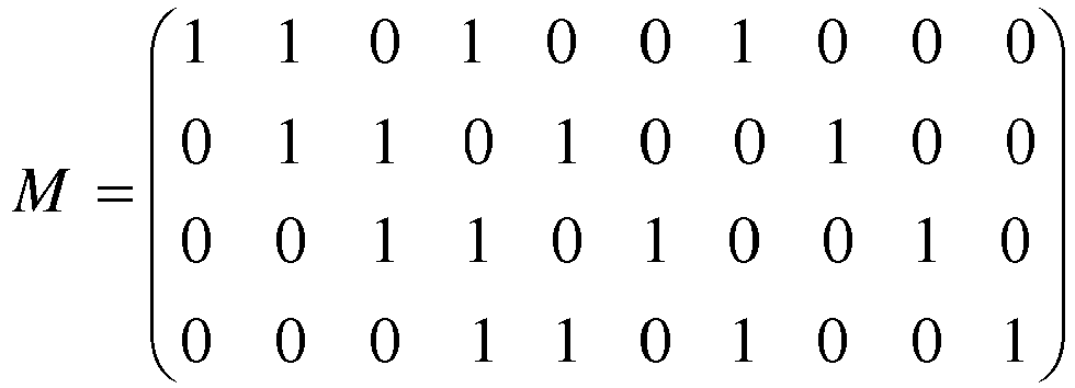
![]()
![]()
![]()
![]()
![]()
![]()
On constate alors que la corrélation entre le signal reçu S et le signal retardé ![]()
![]()
![]()
![]()
![]()
![]()
![]()
![]()
![]()
![]()
Il apparait aussi sur cet exemple que la corrélation entre le signal S et des signaux retardés ![]()
![]()
![]()
![]()
![]()
![]()
![]()
![]()
Notons que ce mode préféré de mise en œuvre trouve une application particulièrement avantageuse dans une configuration où on ne connait pas, à l'émission, l'emplacement des impulsions dans le signal mais où on dispose tout de même de l'information relative audit nombre Nm de données, ce qui est typiquement le cas lorsque les données sont générées par le dispositif émetteur 11 en modulant une séquence d'étalement.Note that this preferred embodiment finds a particularly advantageous application in a configuration where the location of the pulses in the signal is not known, on transmission, but where information relating to said number is still available. N m of data, which is typically the case when the data is generated by the sending
De manière plus générale, il est à noter que les modes de mise en œuvre et de réalisation considérés ci-dessus ont été décrits à titre d'exemples non limitatifs, et que d'autres variantes sont par conséquent envisageables.More generally, it should be noted that the methods of work and embodiment considered above have been described by way of nonlimiting examples, and that other variants are therefore possible.
Notamment, l'invention a été décrite en considérant un système de localisation sans fil UWB. Rien n'exclut cependant, suivant d'autres exemples, de considérer d'autres types de systèmes de communication. L'invention trouve cependant une application particulièrement avantageuse dans les systèmes de communication sans fil à bande ultra large, c'est-à-dire dont la bande passante absolue (à -10 dB par rapport à la puissance mesurée sur la fréquence centrale) est supérieure à 500 mégahertz.In particular, the invention has been described by considering a UWB wireless location system. However, according to other examples, nothing excludes considering other types of communication systems. The invention however finds a particularly advantageous application in ultra-wideband wireless communication systems, that is to say in which the absolute bandwidth (at -10 dB with respect to the power measured on the central frequency) is greater than 500 megahertz.
Claims (14)
- Method for the detection, by a receiver device (12), of a pulse of a signal received by said receiver device (12), said received signal corresponding to data emitted with a predetermined period Tc, each piece of data being encoded by a presence or an absence of a pulse, characterized in that said method comprises:- A step (100) of temporally offsetting of the received signal according to a predetermined number Ns of delays corresponding to different multiples of Tc, in such a way as to generate Ns delayed signals,- A step (200) of correlating, at a time that is a candidate for the detection of a pulse, the received signal with each of the delayed signals, in such a way as to obtain Ns correlation values associated with said candidate time,- A step (300) of calculating a maximum correlation value among the Ns correlation values associated with the candidate time,- A step (400) of detecting a pulse of the received signal according to said maximum correlation value.
- The method according to claim 1, wherein the number of pieces of data is equal to Nc and wherein two pieces of data respectively encoding presences of pulses are separated by at most Nm pieces of data respectively encoding absences of pulses, the number Ns of delayed signals is comprised in the interval [Nm+1,Nc-1] and the respective delays of said delayed signals are determined by

- P The method according to claim 2, wherein the number Ns of delayed signals is equal to Nm+1.
- The method according any of claims 1 to 3, wherein the step (400) of detection of pulses of the received signal comprises a comparison of the maximum correlation value associated with said candidate time to a predetermined threshold value, in such a way that a pulse is detected at said candidate time when the maximum correlation value of said candidate time is greater than said predetermined threshold value.
- The method according any of claims 1 to 4, wherein:- the received signal is correlated with each of the delayed signals at a plurality of candidate times in such a way as to obtain Ns correlation values associated with each candidate time,- the maximum correlation value is calculated among the correlation values associated with said candidate times.
- The method according any of claims 1 to 4, wherein:- the received signal is correlated with each of the delayed signals at a plurality of candidate times in such a way as to obtain Ns correlation values associated with each candidate time,- the maximum correlation value is calculated for each candidate time, among Ns the correlation values associated with said candidate times.- A pulse is detected according to said maximum correlation values.
- The method according any of claims 5 to 6, wherein the candidate times considered comprise an initial time and a final time, and the difference between the final time and the initial time is between Tc/2 and 3×Tc/2.
- A receiver device (12) for the detection of a pulse of a signal received by said receiver device (12), said received signal corresponding to data emitted with a predetermined period Tc, each piece of data being encoded by a presence or an absence of a pulse, characterized in that said receiver device (12) comprises:- means configured to temporally offset the received signal according to a predetermined number Ns de retards of delays corresponding to different multiples of Tc, in such a way as to generate Ns delayed signals,- means configured to correlate, at a time that is a candidate for the detection of a pulse, the received signal with each of the delayed signals, in such a way as to obtain Ns correlation values associated with said candidate time,- means configured to calculate a maximum correlation value among the Ns correlation values associated with the candidate time,- means configured to detect a pulse of the received signal according to said maximum correlation value.
- The receiver device (12) according to claim 8, wherein the number of pieces of data is equal to Nc and wherein two pieces of data respectively encoding a presence of a pulse are separated by at most Nm pieces of data respectively encoding an absence of a pulse, the number Ns of delayed signals is comprised in the interval [Nm+1,Nc-1] and the respective delays of said delayed signals are determined by

- The receiver device (12) according to claim 9, wherein the number Ns of delayed signals is equal to Nm+1.
- The receiver device (12) according to claim 8 to 10, further comprising means configured to compare the maximum correlation value associated with said candidate time to a predetermined threshold value, in such a way that a pulse is detected at said candidate time when the maximum correlation value of said candidate time is greater than said predetermined threshold value.
- The receiver device (12) according to claim 8 to 11, further comprising:- means configured to correlate the received signal with each of the delayed signals at a plurality of candidate times in such a way as to obtain Ns correlation values associated with each candidate time,- means configured to calculate the maximum correlation value among the correlation values associated with said candidate times.
- The receiver device (12) according to claim 8 to 11, further comprising:- means configured to correlate the received signal with each of the delayed signals at a plurality of candidate times in such a way as to obtain Ns correlation values associated with each candidate time,- means configured to calculate a maximum correlation value for each candidate time, among the Ns correlation values associated with said candidate time considered,- means configured to detect a pulse according to said maximum correlation values.
- The receiver device (12) according to claim 12 or claim 13, wherein the candidate times considered comprise an initial time and a final time, and the difference between the final time and the initial time is between Tc/2 et 3×Tc/2.
Applications Claiming Priority (2)
| Application Number | Priority Date | Filing Date | Title |
|---|---|---|---|
| FR1662287A FR3060245B1 (en) | 2016-12-12 | 2016-12-12 | METHOD AND DEVICE FOR DETECTING A PULSE OF A SIGNAL |
| PCT/EP2017/082278 WO2018108837A1 (en) | 2016-12-12 | 2017-12-11 | Method and device for the detection of a pulse of a signal |
Publications (2)
| Publication Number | Publication Date |
|---|---|
| EP3552316A1 EP3552316A1 (en) | 2019-10-16 |
| EP3552316B1 true EP3552316B1 (en) | 2021-11-10 |
Family
ID=58547586
Family Applications (1)
| Application Number | Title | Priority Date | Filing Date |
|---|---|---|---|
| EP17821519.0A Active EP3552316B1 (en) | 2016-12-12 | 2017-12-11 | Method and device for the detection of a pulse of a signal |
Country Status (4)
| Country | Link |
|---|---|
| US (1) | US10651889B2 (en) |
| EP (1) | EP3552316B1 (en) |
| FR (1) | FR3060245B1 (en) |
| WO (1) | WO2018108837A1 (en) |
Families Citing this family (2)
| Publication number | Priority date | Publication date | Assignee | Title |
|---|---|---|---|---|
| GB201613219D0 (en) | 2016-08-01 | 2016-09-14 | Mitraltech Ltd | Minimally-invasive delivery systems |
| GB201720803D0 (en) | 2017-12-13 | 2018-01-24 | Mitraltech Ltd | Prosthetic Valve and delivery tool therefor |
Family Cites Families (6)
| Publication number | Priority date | Publication date | Assignee | Title |
|---|---|---|---|---|
| US6810087B2 (en) * | 2000-01-04 | 2004-10-26 | General Electric Company | Ultra-wideband communications system |
| KR20050066562A (en) * | 2003-12-26 | 2005-06-30 | 삼성전자주식회사 | Method for embodying frame preamble in wireless communication based on ofdm, and method for acquiring frame synchronization and searching cells using the preamble |
| KR100759514B1 (en) * | 2006-07-10 | 2007-09-18 | 삼성전기주식회사 | Demodulator for wpan and mathod thereof |
| JP4911220B2 (en) * | 2009-11-30 | 2012-04-04 | セイコーエプソン株式会社 | Satellite signal capturing method and satellite signal receiving apparatus |
| FR3003357B1 (en) * | 2013-03-15 | 2015-03-20 | Thales Sa | METHOD AND DEVICE FOR COMPRESSING A BROADBAND RADIO NAVIGATION SIGNAL, METHOD AND APPARATUS THEREFOR FOR CALCULATING THE CORRELATION FUNCTION OF THE SPREADING CODE OF THE COMPRESSED SIGNAL |
| WO2015158296A1 (en) * | 2014-04-16 | 2015-10-22 | 上海数字电视国家工程研究中心有限公司 | Method and apparatus for receiving preamble symbol |
-
2016
- 2016-12-12 FR FR1662287A patent/FR3060245B1/en not_active Expired - Fee Related
-
2017
- 2017-12-11 WO PCT/EP2017/082278 patent/WO2018108837A1/en unknown
- 2017-12-11 EP EP17821519.0A patent/EP3552316B1/en active Active
- 2017-12-11 US US16/468,504 patent/US10651889B2/en active Active
Also Published As
| Publication number | Publication date |
|---|---|
| US20200091956A1 (en) | 2020-03-19 |
| FR3060245A1 (en) | 2018-06-15 |
| FR3060245B1 (en) | 2019-05-17 |
| US10651889B2 (en) | 2020-05-12 |
| EP3552316A1 (en) | 2019-10-16 |
| WO2018108837A1 (en) | 2018-06-21 |
Similar Documents
| Publication | Publication Date | Title |
|---|---|---|
| EP2929364B1 (en) | Method for the passive localization of radar transmitters | |
| EP3552316B1 (en) | Method and device for the detection of a pulse of a signal | |
| WO2018083070A1 (en) | Method and receiver device for estimating the instant of arrival of a radio signal, locating method and system | |
| EP3171195A2 (en) | Method for locating a beacon | |
| EP3803452B1 (en) | Method for determining a characteristic of a receiver in a medium and system implementing this method | |
| EP2587691A1 (en) | Method for the coordinated processing of signals transmitted by beacons | |
| WO2016184806A1 (en) | Radio frequency signal transmission in a real-time locating system | |
| EP2909945B1 (en) | Method for the determination of the time of arrival of an uwb pulse and corresponding receiver | |
| FR2946482A1 (en) | METHOD FOR DETECTING A MESSAGE ISSUED BY A S MODE INTERROGATOR OR ANSWERING MACHINE | |
| EP2908154B1 (en) | Method for correlating a received satellite radio-navigation signal and correlation device implementing the method | |
| EP2607915B1 (en) | Method for locating emitting sources by using the mutual coupling of a small-base antenna array and slow-switching single-channel receiving system implementing the method | |
| FR3011086A1 (en) | METHOD FOR JOINTLY SYNCHRONIZING, IDENTIFYING, MEASURING, ESTIMATING THE PROPAGATION FILTER AND LOCATING USEFUL AND INTERFERING TRANSMITTERS | |
| CA2830604A1 (en) | Detection process and system for broadcasting signals emitted by terrestrial sources and received by a satellite | |
| WO2020127496A1 (en) | Methods and devices for transmitting a bit sequence and estimating the arrival time of same | |
| EP4009068A1 (en) | System and method for intercepting non-discursive electromagnetic signals emitted in a wide frequency band | |
| FR3104735A1 (en) | PROCESS FOR PASSIVE LOCATION OF TRANSMITTERS BY MEASURING DIFFERENTIAL TIME OF ARRIVAL (TDOA) | |
| EP3377914B1 (en) | Method for locating a beacon by angles of arrival | |
| FR3135371A1 (en) | METHOD FOR ENCODING AND DECODING A UWB MESSAGE USING MODULATION GENERATING A TIME SHIFT OF THE DATA BITS | |
| FR2973615A1 (en) | METHOD OF INTEGRATION OF SIGNALS ISSUED FROM A TRANSMITTER TO AT LEAST ONE ULTRA-BAND-WIDE RECEIVER (ULB) AND DEVICE FOR IMPLEMENTING THE METHOD | |
| FR2902195A1 (en) | Radio frequency signal arrival time determining method for geographic localization of mobile telephone, involves crosscorrelating useful signals with reference signal, where arrival time is determined by summing time and time-based position | |
| WO2020245325A1 (en) | Method and device for estimating the time of arrival of a message | |
| WO2023057729A1 (en) | Method and device for detecting satellite signal decoying | |
| WO2011000660A1 (en) | Method for detecting substantially periodic series of bursts of substantially sinusoidal signals | |
| FR3080461A1 (en) | METHOD FOR GEOLOCATING A TRANSMITTER, GEOLOCATION SYSTEM AND COMPUTER PROGRAM PRODUCT THEREOF | |
| EP3306350A1 (en) | Detection module of a disturbance signal while initial receiving by a receiver of navigation information, receiver comprising such module, associated method and computer program product |
Legal Events
| Date | Code | Title | Description |
|---|---|---|---|
| STAA | Information on the status of an ep patent application or granted ep patent |
Free format text: STATUS: UNKNOWN |
|
| STAA | Information on the status of an ep patent application or granted ep patent |
Free format text: STATUS: THE INTERNATIONAL PUBLICATION HAS BEEN MADE |
|
| PUAI | Public reference made under article 153(3) epc to a published international application that has entered the european phase |
Free format text: ORIGINAL CODE: 0009012 |
|
| STAA | Information on the status of an ep patent application or granted ep patent |
Free format text: STATUS: REQUEST FOR EXAMINATION WAS MADE |
|
| 17P | Request for examination filed |
Effective date: 20190712 |
|
| AK | Designated contracting states |
Kind code of ref document: A1 Designated state(s): AL AT BE BG CH CY CZ DE DK EE ES FI FR GB GR HR HU IE IS IT LI LT LU LV MC MK MT NL NO PL PT RO RS SE SI SK SM TR |
|
| AX | Request for extension of the european patent |
Extension state: BA ME |
|
| DAV | Request for validation of the european patent (deleted) | ||
| DAX | Request for extension of the european patent (deleted) | ||
| RAP1 | Party data changed (applicant data changed or rights of an application transferred) |
Owner name: UWINLOC |
|
| GRAP | Despatch of communication of intention to grant a patent |
Free format text: ORIGINAL CODE: EPIDOSNIGR1 |
|
| STAA | Information on the status of an ep patent application or granted ep patent |
Free format text: STATUS: GRANT OF PATENT IS INTENDED |
|
| INTG | Intention to grant announced |
Effective date: 20210602 |
|
| GRAS | Grant fee paid |
Free format text: ORIGINAL CODE: EPIDOSNIGR3 |
|
| GRAA | (expected) grant |
Free format text: ORIGINAL CODE: 0009210 |
|
| STAA | Information on the status of an ep patent application or granted ep patent |
Free format text: STATUS: THE PATENT HAS BEEN GRANTED |
|
| AK | Designated contracting states |
Kind code of ref document: B1 Designated state(s): AL AT BE BG CH CY CZ DE DK EE ES FI FR GB GR HR HU IE IS IT LI LT LU LV MC MK MT NL NO PL PT RO RS SE SI SK SM TR |
|
| REG | Reference to a national code |
Ref country code: GB Ref legal event code: FG4D Free format text: NOT ENGLISH |
|
| RIN1 | Information on inventor provided before grant (corrected) |
Inventor name: MENNEKENS, JAN |
|
| REG | Reference to a national code |
Ref country code: AT Ref legal event code: REF Ref document number: 1447025 Country of ref document: AT Kind code of ref document: T Effective date: 20211115 Ref country code: CH Ref legal event code: EP |
|
| REG | Reference to a national code |
Ref country code: DE Ref legal event code: R096 Ref document number: 602017049201 Country of ref document: DE |
|
| REG | Reference to a national code |
Ref country code: IE Ref legal event code: FG4D Free format text: LANGUAGE OF EP DOCUMENT: FRENCH |
|
| REG | Reference to a national code |
Ref country code: LT Ref legal event code: MG9D |
|
| REG | Reference to a national code |
Ref country code: NL Ref legal event code: MP Effective date: 20211110 |
|
| REG | Reference to a national code |
Ref country code: AT Ref legal event code: MK05 Ref document number: 1447025 Country of ref document: AT Kind code of ref document: T Effective date: 20211110 |
|
| PG25 | Lapsed in a contracting state [announced via postgrant information from national office to epo] |
Ref country code: RS Free format text: LAPSE BECAUSE OF FAILURE TO SUBMIT A TRANSLATION OF THE DESCRIPTION OR TO PAY THE FEE WITHIN THE PRESCRIBED TIME-LIMIT Effective date: 20211110 Ref country code: LT Free format text: LAPSE BECAUSE OF FAILURE TO SUBMIT A TRANSLATION OF THE DESCRIPTION OR TO PAY THE FEE WITHIN THE PRESCRIBED TIME-LIMIT Effective date: 20211110 Ref country code: FI Free format text: LAPSE BECAUSE OF FAILURE TO SUBMIT A TRANSLATION OF THE DESCRIPTION OR TO PAY THE FEE WITHIN THE PRESCRIBED TIME-LIMIT Effective date: 20211110 Ref country code: BG Free format text: LAPSE BECAUSE OF FAILURE TO SUBMIT A TRANSLATION OF THE DESCRIPTION OR TO PAY THE FEE WITHIN THE PRESCRIBED TIME-LIMIT Effective date: 20220210 Ref country code: AT Free format text: LAPSE BECAUSE OF FAILURE TO SUBMIT A TRANSLATION OF THE DESCRIPTION OR TO PAY THE FEE WITHIN THE PRESCRIBED TIME-LIMIT Effective date: 20211110 |
|
| PG25 | Lapsed in a contracting state [announced via postgrant information from national office to epo] |
Ref country code: IS Free format text: LAPSE BECAUSE OF FAILURE TO SUBMIT A TRANSLATION OF THE DESCRIPTION OR TO PAY THE FEE WITHIN THE PRESCRIBED TIME-LIMIT Effective date: 20220310 Ref country code: SE Free format text: LAPSE BECAUSE OF FAILURE TO SUBMIT A TRANSLATION OF THE DESCRIPTION OR TO PAY THE FEE WITHIN THE PRESCRIBED TIME-LIMIT Effective date: 20211110 Ref country code: PT Free format text: LAPSE BECAUSE OF FAILURE TO SUBMIT A TRANSLATION OF THE DESCRIPTION OR TO PAY THE FEE WITHIN THE PRESCRIBED TIME-LIMIT Effective date: 20220310 Ref country code: PL Free format text: LAPSE BECAUSE OF FAILURE TO SUBMIT A TRANSLATION OF THE DESCRIPTION OR TO PAY THE FEE WITHIN THE PRESCRIBED TIME-LIMIT Effective date: 20211110 Ref country code: NO Free format text: LAPSE BECAUSE OF FAILURE TO SUBMIT A TRANSLATION OF THE DESCRIPTION OR TO PAY THE FEE WITHIN THE PRESCRIBED TIME-LIMIT Effective date: 20220210 Ref country code: NL Free format text: LAPSE BECAUSE OF FAILURE TO SUBMIT A TRANSLATION OF THE DESCRIPTION OR TO PAY THE FEE WITHIN THE PRESCRIBED TIME-LIMIT Effective date: 20211110 Ref country code: LV Free format text: LAPSE BECAUSE OF FAILURE TO SUBMIT A TRANSLATION OF THE DESCRIPTION OR TO PAY THE FEE WITHIN THE PRESCRIBED TIME-LIMIT Effective date: 20211110 Ref country code: HR Free format text: LAPSE BECAUSE OF FAILURE TO SUBMIT A TRANSLATION OF THE DESCRIPTION OR TO PAY THE FEE WITHIN THE PRESCRIBED TIME-LIMIT Effective date: 20211110 Ref country code: GR Free format text: LAPSE BECAUSE OF FAILURE TO SUBMIT A TRANSLATION OF THE DESCRIPTION OR TO PAY THE FEE WITHIN THE PRESCRIBED TIME-LIMIT Effective date: 20220211 Ref country code: ES Free format text: LAPSE BECAUSE OF FAILURE TO SUBMIT A TRANSLATION OF THE DESCRIPTION OR TO PAY THE FEE WITHIN THE PRESCRIBED TIME-LIMIT Effective date: 20211110 |
|
| PG25 | Lapsed in a contracting state [announced via postgrant information from national office to epo] |
Ref country code: SM Free format text: LAPSE BECAUSE OF FAILURE TO SUBMIT A TRANSLATION OF THE DESCRIPTION OR TO PAY THE FEE WITHIN THE PRESCRIBED TIME-LIMIT Effective date: 20211110 Ref country code: SK Free format text: LAPSE BECAUSE OF FAILURE TO SUBMIT A TRANSLATION OF THE DESCRIPTION OR TO PAY THE FEE WITHIN THE PRESCRIBED TIME-LIMIT Effective date: 20211110 Ref country code: RO Free format text: LAPSE BECAUSE OF FAILURE TO SUBMIT A TRANSLATION OF THE DESCRIPTION OR TO PAY THE FEE WITHIN THE PRESCRIBED TIME-LIMIT Effective date: 20211110 Ref country code: EE Free format text: LAPSE BECAUSE OF FAILURE TO SUBMIT A TRANSLATION OF THE DESCRIPTION OR TO PAY THE FEE WITHIN THE PRESCRIBED TIME-LIMIT Effective date: 20211110 Ref country code: DK Free format text: LAPSE BECAUSE OF FAILURE TO SUBMIT A TRANSLATION OF THE DESCRIPTION OR TO PAY THE FEE WITHIN THE PRESCRIBED TIME-LIMIT Effective date: 20211110 Ref country code: CZ Free format text: LAPSE BECAUSE OF FAILURE TO SUBMIT A TRANSLATION OF THE DESCRIPTION OR TO PAY THE FEE WITHIN THE PRESCRIBED TIME-LIMIT Effective date: 20211110 |
|
| REG | Reference to a national code |
Ref country code: CH Ref legal event code: PL |
|
| REG | Reference to a national code |
Ref country code: DE Ref legal event code: R097 Ref document number: 602017049201 Country of ref document: DE |
|
| PG25 | Lapsed in a contracting state [announced via postgrant information from national office to epo] |
Ref country code: MC Free format text: LAPSE BECAUSE OF FAILURE TO SUBMIT A TRANSLATION OF THE DESCRIPTION OR TO PAY THE FEE WITHIN THE PRESCRIBED TIME-LIMIT Effective date: 20211110 |
|
| PLBE | No opposition filed within time limit |
Free format text: ORIGINAL CODE: 0009261 |
|
| STAA | Information on the status of an ep patent application or granted ep patent |
Free format text: STATUS: NO OPPOSITION FILED WITHIN TIME LIMIT |
|
| REG | Reference to a national code |
Ref country code: BE Ref legal event code: MM Effective date: 20211231 |
|
| 26N | No opposition filed |
Effective date: 20220811 |
|
| PG25 | Lapsed in a contracting state [announced via postgrant information from national office to epo] |
Ref country code: LU Free format text: LAPSE BECAUSE OF NON-PAYMENT OF DUE FEES Effective date: 20211211 Ref country code: IE Free format text: LAPSE BECAUSE OF NON-PAYMENT OF DUE FEES Effective date: 20211211 Ref country code: AL Free format text: LAPSE BECAUSE OF FAILURE TO SUBMIT A TRANSLATION OF THE DESCRIPTION OR TO PAY THE FEE WITHIN THE PRESCRIBED TIME-LIMIT Effective date: 20211110 |
|
| PG25 | Lapsed in a contracting state [announced via postgrant information from national office to epo] |
Ref country code: SI Free format text: LAPSE BECAUSE OF FAILURE TO SUBMIT A TRANSLATION OF THE DESCRIPTION OR TO PAY THE FEE WITHIN THE PRESCRIBED TIME-LIMIT Effective date: 20211110 Ref country code: BE Free format text: LAPSE BECAUSE OF NON-PAYMENT OF DUE FEES Effective date: 20211231 |
|
| PG25 | Lapsed in a contracting state [announced via postgrant information from national office to epo] |
Ref country code: LI Free format text: LAPSE BECAUSE OF NON-PAYMENT OF DUE FEES Effective date: 20211231 Ref country code: CH Free format text: LAPSE BECAUSE OF NON-PAYMENT OF DUE FEES Effective date: 20211231 |
|
| PG25 | Lapsed in a contracting state [announced via postgrant information from national office to epo] |
Ref country code: IT Free format text: LAPSE BECAUSE OF FAILURE TO SUBMIT A TRANSLATION OF THE DESCRIPTION OR TO PAY THE FEE WITHIN THE PRESCRIBED TIME-LIMIT Effective date: 20211110 |
|
| PG25 | Lapsed in a contracting state [announced via postgrant information from national office to epo] |
Ref country code: CY Free format text: LAPSE BECAUSE OF FAILURE TO SUBMIT A TRANSLATION OF THE DESCRIPTION OR TO PAY THE FEE WITHIN THE PRESCRIBED TIME-LIMIT Effective date: 20211110 |
|
| PG25 | Lapsed in a contracting state [announced via postgrant information from national office to epo] |
Ref country code: HU Free format text: LAPSE BECAUSE OF FAILURE TO SUBMIT A TRANSLATION OF THE DESCRIPTION OR TO PAY THE FEE WITHIN THE PRESCRIBED TIME-LIMIT; INVALID AB INITIO Effective date: 20171211 |
|
| PGFP | Annual fee paid to national office [announced via postgrant information from national office to epo] |
Ref country code: GB Payment date: 20231221 Year of fee payment: 7 |
|
| PGFP | Annual fee paid to national office [announced via postgrant information from national office to epo] |
Ref country code: FR Payment date: 20231220 Year of fee payment: 7 Ref country code: DE Payment date: 20231208 Year of fee payment: 7 |