EP3552293B1 - Leistungssteuerung von wechselrichtern einer fotovoltaikanlage zur teilnahme an der frequenzregulation des elektrischen versorgungsnetzes - Google Patents
Leistungssteuerung von wechselrichtern einer fotovoltaikanlage zur teilnahme an der frequenzregulation des elektrischen versorgungsnetzes Download PDFInfo
- Publication number
- EP3552293B1 EP3552293B1 EP17811499.7A EP17811499A EP3552293B1 EP 3552293 B1 EP3552293 B1 EP 3552293B1 EP 17811499 A EP17811499 A EP 17811499A EP 3552293 B1 EP3552293 B1 EP 3552293B1
- Authority
- EP
- European Patent Office
- Prior art keywords
- inverters
- power
- mpp
- reserve
- setpoint
- Prior art date
- Legal status (The legal status is an assumption and is not a legal conclusion. Google has not performed a legal analysis and makes no representation as to the accuracy of the status listed.)
- Active
Links
Images



Classifications
-
- H—ELECTRICITY
- H02—GENERATION; CONVERSION OR DISTRIBUTION OF ELECTRIC POWER
- H02J—ELECTRIC POWER NETWORKS; CIRCUIT ARRANGEMENTS OR SYSTEMS FOR SUPPLYING OR DISTRIBUTING ELECTRIC POWER; SYSTEMS FOR STORING ELECTRIC ENERGY
- H02J3/00—Circuit arrangements for AC mains or AC distribution networks
- H02J3/38—Arrangements for feeding a single network from two or more generators or sources in parallel; Arrangements for feeding already energised networks from additional generators or sources in parallel
- H02J3/381—Dispersed generators
-
- G—PHYSICS
- G05—CONTROLLING; REGULATING
- G05F—SYSTEMS FOR REGULATING ELECTRIC OR MAGNETIC VARIABLES
- G05F1/00—Automatic systems in which deviations of an electric quantity from one or more predetermined values are detected at the output of the system and fed back to a device within the system to restore the detected quantity to its predetermined value or values, i.e. retroactive systems
- G05F1/66—Regulating electric power
- G05F1/67—Regulating electric power to the maximum power available from a generator, e.g. from solar cell
-
- H—ELECTRICITY
- H02—GENERATION; CONVERSION OR DISTRIBUTION OF ELECTRIC POWER
- H02J—ELECTRIC POWER NETWORKS; CIRCUIT ARRANGEMENTS OR SYSTEMS FOR SUPPLYING OR DISTRIBUTING ELECTRIC POWER; SYSTEMS FOR STORING ELECTRIC ENERGY
- H02J3/00—Circuit arrangements for AC mains or AC distribution networks
- H02J3/38—Arrangements for feeding a single network from two or more generators or sources in parallel; Arrangements for feeding already energised networks from additional generators or sources in parallel
-
- H—ELECTRICITY
- H02—GENERATION; CONVERSION OR DISTRIBUTION OF ELECTRIC POWER
- H02J—ELECTRIC POWER NETWORKS; CIRCUIT ARRANGEMENTS OR SYSTEMS FOR SUPPLYING OR DISTRIBUTING ELECTRIC POWER; SYSTEMS FOR STORING ELECTRIC ENERGY
- H02J3/00—Circuit arrangements for AC mains or AC distribution networks
- H02J3/38—Arrangements for feeding a single network from two or more generators or sources in parallel; Arrangements for feeding already energised networks from additional generators or sources in parallel
- H02J3/46—Controlling the sharing of generated power between the generators, sources or networks
-
- H—ELECTRICITY
- H02—GENERATION; CONVERSION OR DISTRIBUTION OF ELECTRIC POWER
- H02J—ELECTRIC POWER NETWORKS; CIRCUIT ARRANGEMENTS OR SYSTEMS FOR SUPPLYING OR DISTRIBUTING ELECTRIC POWER; SYSTEMS FOR STORING ELECTRIC ENERGY
- H02J2101/00—Supply or distribution of decentralised, dispersed or local electric power generation
- H02J2101/20—Dispersed power generation using renewable energy sources
- H02J2101/22—Solar energy
- H02J2101/24—Photovoltaics
-
- H—ELECTRICITY
- H02—GENERATION; CONVERSION OR DISTRIBUTION OF ELECTRIC POWER
- H02J—ELECTRIC POWER NETWORKS; CIRCUIT ARRANGEMENTS OR SYSTEMS FOR SUPPLYING OR DISTRIBUTING ELECTRIC POWER; SYSTEMS FOR STORING ELECTRIC ENERGY
- H02J2101/00—Supply or distribution of decentralised, dispersed or local electric power generation
- H02J2101/20—Dispersed power generation using renewable energy sources
- H02J2101/22—Solar energy
- H02J2101/24—Photovoltaics
- H02J2101/25—Photovoltaics involving maximum power point tracking control for photovoltaic sources
-
- H—ELECTRICITY
- H02—GENERATION; CONVERSION OR DISTRIBUTION OF ELECTRIC POWER
- H02J—ELECTRIC POWER NETWORKS; CIRCUIT ARRANGEMENTS OR SYSTEMS FOR SUPPLYING OR DISTRIBUTING ELECTRIC POWER; SYSTEMS FOR STORING ELECTRIC ENERGY
- H02J3/00—Circuit arrangements for AC mains or AC distribution networks
- H02J3/04—Arrangements for connecting networks of the same frequency but supplied from different sources
-
- Y—GENERAL TAGGING OF NEW TECHNOLOGICAL DEVELOPMENTS; GENERAL TAGGING OF CROSS-SECTIONAL TECHNOLOGIES SPANNING OVER SEVERAL SECTIONS OF THE IPC; TECHNICAL SUBJECTS COVERED BY FORMER USPC CROSS-REFERENCE ART COLLECTIONS [XRACs] AND DIGESTS
- Y02—TECHNOLOGIES OR APPLICATIONS FOR MITIGATION OR ADAPTATION AGAINST CLIMATE CHANGE
- Y02E—REDUCTION OF GREENHOUSE GAS [GHG] EMISSIONS, RELATED TO ENERGY GENERATION, TRANSMISSION OR DISTRIBUTION
- Y02E10/00—Energy generation through renewable energy sources
- Y02E10/50—Photovoltaic [PV] energy
- Y02E10/56—Power conversion systems, e.g. maximum power point trackers
-
- Y—GENERAL TAGGING OF NEW TECHNOLOGICAL DEVELOPMENTS; GENERAL TAGGING OF CROSS-SECTIONAL TECHNOLOGIES SPANNING OVER SEVERAL SECTIONS OF THE IPC; TECHNICAL SUBJECTS COVERED BY FORMER USPC CROSS-REFERENCE ART COLLECTIONS [XRACs] AND DIGESTS
- Y02—TECHNOLOGIES OR APPLICATIONS FOR MITIGATION OR ADAPTATION AGAINST CLIMATE CHANGE
- Y02P—CLIMATE CHANGE MITIGATION TECHNOLOGIES IN THE PRODUCTION OR PROCESSING OF GOODS
- Y02P80/00—Climate change mitigation technologies for sector-wide applications
- Y02P80/20—Climate change mitigation technologies for sector-wide applications using renewable energy
Definitions
- the present invention relates to the management of a photovoltaic installation for the production of electricity, comprising a plurality of inverters ensuring the connection between the photovoltaic panels of the installation and an electricity distribution network.
- a conventional generator can do this by setting the nominal frequency set point of his installation below the maximum power of the installation. So for example, if the frequency is below its nominal value of 50 Hz, for example 49.8 Hz, then it is desired that the installation produce more electrical energy (more precisely active power) to compensate for the lack of production and to ensure that the network frequency returns to its nominal value of 50 Hz. Conversely, producers may be asked to temporarily reduce their production in the event of an over-frequency on the network (frequency higher than the nominal frequency, for example 50.2 Hz instead of 50 Hz in France, symptomatic of an overproduction of electrical energy in the system).
- dynamic frequency support by very rapid release of the reserve, improves the quality of supply in sensitive networks, such as island systems, by intervening very quickly following a disturbance.
- photovoltaic installations are usually controlled so that the photovoltaic panels extract the maximum available solar power at all times.
- This control is done by the internal control of each inverter, with algorithms which make it possible to find the optimal operating point of the solar panel (current, voltage) in order to extract a maximum of power.
- the type of algorithm usually used to perform this control is called “Maximum Power Point Tracking” (“MPPT” hereafter) and consists of finding the maximum power supplied by each panel, as a function of the voltage applied to its terminals. .
- MPP Maximum Power Point
- the power produced can be reduced by deviating from the voltage corresponding to the MPP operating point of the panels supplying it.
- Such an achievement is proposed in the document FR 15 59128 on behalf of the plaintiff.
- this strategy involves the internal control of the inverter connected to a panel or group of photovoltaic panels.
- the inverter is generally locked by the manufacturer so that it can only be used as a “black box” by the operator.
- the present invention improves this situation.
- the present invention simply uses the current ability of known inverters to determine their operating point making it possible to deliver a maximum power, which thus makes it possible to determine the possible power reserve of the installation, by cyclical determinations of the maximum powers of all inverters. Some of these inverters (k inverters) are then controlled in order to reach this maximum power while the other inverters (N-k inverters) can participate in the constitution of reserve, and this successively (for example by circular permutation). The invention therefore only requires a computer device communicating with the inverters to control their operation according to such a method.
- a time delay is applied between the transmission of the instructions to the k inverters and the obtaining of the maximum power measurements of the k inverters, in order to take into account a search latency by each inverter for the maximum power that can be obtained. produced.
- This search can typically be a pre-existing routine (called “MPPT”) and described in more detail below.
- each setpoint for the k inverters to reach the maximum power comprises a time ramp setpoint to be respected, for a progressive increase in the power produced by each of the k inverters.
- the setpoint of target power to this given inverter comprises a time ramp setpoint to be observed for a progressive reduction in the power produced by this given inverter down to the target power.
- the increase and decrease ramps are advantageously chosen to conserve on all the N inverters an overall power produced corresponding to said overall power to be produced. This precaution makes it possible to smooth the overall power produced by making it conform to the calculated global setpoint, as will be seen in particular on the figure 4B discussed below.
- each target power setpoint is determined so as to respect the same difference between the target power and the maximum power for all the N-k complementary inverters. Such an embodiment makes it possible to distribute the reserve to be constituted over the N-k inverters which are not at their maximum produced power.
- the aforementioned power reserve of the installation is constituted with a view to releasing all or part of said reserve as a function of a frequency deviation from a nominal frequency of an electricity distribution network to which the inverters are connected.
- the aforementioned information relating to a quantity of reserve power to be constituted can be a directly measured value of the frequency of the distribution network, on the basis of which said quantity of reserve power to be constituted is calculated.
- this information relating to a quantity of reserve power to be constituted may be a reserve constitution instruction received from a managing entity of the distribution network.
- k following inverters to replace k previous inverters from a previous iteration (thus respecting the same number k from one iteration to the next).
- the present invention also relates to a computer program (and its memory medium) comprising instructions for the implementation of the above method, when this program is executed by a processor.
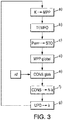
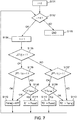
- the figures 3 and 5 are possible flowcharts of the general algorithm of such a program.
- the figures 6 and 7 are possible flow charts of particular subroutines of this general algorithm.
- This process allows pre-existing photovoltaic installations to be adapted, without replacing current inverters or providing new sensors, to participate in frequency adjustment.
- the present invention relates to the management of an installation of photovoltaic panels as illustrated in figure 1 .
- the installation comprises several photovoltaic panels connected by PV1, PV2, ..., PVN groups to respective inverters OND1, OND2, ..., ONDN.
- the panels produce electricity by photovoltaic effect and each inverter to which they are connected can be controlled in power produced Pp1, Pp2, PpN at the output of each inverter, by a computer device (computer type) DIS.
- the device DIS can send a setpoint CONS1, CONS2, ..., CONSN, for each inverter OND1, OND2, ..., ONDN.
- this setpoint for an inverter can be to reach a maximum produced power P MPP .
- this power value P MPP has been reached by an inverter, the latter usually transmits to the device DIS the maximum power reached P MPP .
- the device DIS can know at any time a measurement of this maximum attainable power P MPP .
- This P MPP value is variable and of course depends on the sunshine conditions (it is higher the more sunshine is).
- the value P MPP that each inverter transmits to the DIS device represents a measurement (arrows MES1, MES2, ..., MESN) at a current instant of the maximum power that can be reached and that this inverter can deliver (and thus depending on the degree of sunshine at this current moment).
- the invention therefore proposes to take advantage of these possible modes of operation to constitute a reserve of electrical power generated by the panels and thus contribute to the balance of the frequency of the electrical distribution network (as the aim described in the document FR 15 59128 ).
- a nominal frequency in France of 50 Hz.
- the higher the frequency ( ⁇ ⁇ > 0) the more the power produced should be reduced.
- the lower the frequency ( ⁇ ⁇ ⁇ 0) the more the power reserve produced should be released.
- the inverters can be controlled so as to deliver the maximum power P MPP of all the inverters.
- the device obtains a current value of the network frequency, or a deviation from its nominal value ⁇ ⁇ .
- the DIS device can receive (or alternatively directly measure) the value ⁇ ⁇ via a communication interface COM.
- the device further comprises a processor PROC and a permanent memory MEM.
- This memory MEM can typically store computer program instruction codes within the meaning of the invention. These instruction codes can be read by the processor PROC for executing the method according to the invention (described in detail below).
- the device may also include an STO work memory for storing temporary data, in particular the maximum powers P MPP sent by the inverters to the device via the communication interface with the INT inverters, which can also be used to send the set points. power to be produced to inverters.
- the memories MEM and STO can be the same memory unit of the device.
- the device may include an internal clock HOR.
- the aim is in particular to constitute the power reserve on the photovoltaic installation and to optimize its constitution, so as to limit the lost producible and to maximize the availability of the reserve.
- the invention is therefore aimed at a method, implemented by computer means (typically the DIS device), for controlling the power production of photovoltaic panels by sending precisely calculated active power instructions to the individual inverters of an installation (called “ plant ”below), in order to have at any time an estimate of the maximum available power of the plant (called“ overall MPP ”of the plant) and to be able to achieve a global power setpoint, less than or equal to the global MPP .
- This process does not involve any modification of the internal controllers of the inverters (algorithm factitiously shifting the MPP for example, as described in the document FR 15 59128 ), which can be considered as “black box” type systems with a power setpoint at the input and a realized and measured power at the output.
- the method can be compatible with existing installations using commercially available inverters, provided that the inverters can receive power setpoints from an external device (for example a PLC, a computer, etc.), and that their time response to these instructions is sufficiently short (typically less than 5 seconds).
- a global reserve is constituted at the plant level by placing at each instant a selected number Nk of inverters at a power less than or equal to their MPP, by sending them power instructions less than or equal to the estimates of their respective MPP .
- the MPP estimates are updated cyclically to ensure rotation between the inverters that are at the MPP and those that perform the reserve function.
- an estimate of the overall MPP of the plant can be known at any time (by taking all the MPP values measured and recorded one after the other on all the N inverters).
- the overall power can then be controlled to ensure reserve and adjust the frequency of the network, without requiring any sensors other than the usual power sensors for inverters (commercial inverters already being equipped with these sensors).
- a network frequency sensor at the central connection point or simply a communication module to receive an external adjustment signal (for example a signal from a network manager). . No changes to internal controllers inverters or a priori knowledge of the signs of behavior is necessary.
- MPP est_total 18 kW.
- the OND2 inverter now operates at the MPP (instead of the OND1 inverter), and the reserve is now placed on the OND1 and OND3 inverters.
- the estimated MPP and the measured power of the inverter OND2: its MPP has changed and has become 6.5kW.
- the new MPP value of the OND2 inverter is then recorded at the end of this phase to update the overall MPP and correct the setpoints for the next phase in order to maintain the 4 kW reserve.
- the OND3 inverter switches to MPP. We see that his MPP is unchanged.
- the inverter OND1 is then returned to its MPP again to restart the cycle, and to update the MPP of the inverter OND1 in the typical case where it has changed since its last measurement.
- FIGS. 4A and 4B show a test of the process in real conditions on an installation made up of three inverters (each with a maximum power of 15 kW), controlled in power by a DIS computer (PLC) which sends active power instructions to the inverters according to the measurements power received from inverters.
- PLC DIS computer
- a synthetic frequency profile of the network f is used ( figure 4A ) to test the response of the installation (Pp1 + Pp2 + Pp3 corresponding to the sum of the powers produced by all three inverters) to variations in network frequency.
- the figure 4B validates correct multi-inverter operation according to the method of the invention.
- the power plant is set to MPP), and the total power obtained (Pp1 + Pp2 + Pp3) is indeed that expected and corresponding to the overall CONSglobal setpoint, with very little error except at the maximum power requested since it cannot exceed the sum of the P MPPs of the three inverters.
- the frequency adjustment is functioning correctly: the overall power responds well to variations in frequency.
- the frequency increases, the power decreases, and conversely when the frequency decreases, the power of the plant increases to support the network.
- the curve (Pp1 + Pp2 + Pp3) representing the variation in the overall power produced as a function of these network frequency variations follows the setpoint well and thus shows that it is indeed possible to carry out a quality adjustment.
- the power control of the inverters is based on the principle of the cyclic process presented previously with reference to the figure 3 .
- a cyclic sweep of one inverter among three inverters is shown.
- Other scanning strategies are possible to improve the estimation of the MPP or to have available the maximum controllable power at any time. Some of these strategies may be based, for example, on measuring the direct voltage (DC) at the terminals of the panels.
- DC direct voltage
- one inverter can (can) be placed at its (their) MPP, while the other (both others) follows (follow) an imposed power setpoint.
- each inverter can have its own MPP, different from the MPP of another inverter (due to the number of panels to which it is connected, or their own degradation).
- the figure 5 illustrates the algorithm corresponding to an embodiment detail integrating the first initialization step S1, presented above.
- T init the inverters are all controlled by the MPP.
- the time T init must be long enough for the MPPs to stabilize (time necessary for the internal MPPT algorithm of each inverter to converge). This value depends on the inverter model and the manufacturer's indications, but is in the order of 10-20 seconds for a commercial inverter today. No reserves are guaranteed during this phase.
- the initialization ends as soon as the initialization time has elapsed, and the frequency tuning can actually start at the following steps.
- the estimated values of the MPPs of each inverter are stored in the memory of the control device DIS.
- step S3 These values are updated in step S3 as soon as each "phase" of the cycle is completed (arrow OK at the output of test S2), and a certain number k of inverters have been commanded to the MPP to obtain a value. update their MPP.
- the principle diagram for this step S3 of updating the MPP estimates is presented on the figure 6 commented below, for a number N of inverters.
- test S32 as long as the counter i is less than the total number of inverters N (arrow OK), it is possible to update the values of MPP stored with measurements obtained in the last cycle carried out.
- step S33 this MPP update routine may stop. Otherwise, in step S34, the counter i is first incremented (to designate a next inverter), then in step S35, a test is carried out to determine whether this inverter i is currently placed at its MPP, at which case (arrow OK-S35) the output power measured on this inverter Pmes (i) corresponds to its estimated MPP (MPPest (i)) and can be stored in memory at step S36. Otherwise (arrow KO-S35), the estimated MPP of the current inverter i remains unchanged, as it is currently stored in the memory of the device DIS (step S37).
- this overall MPP value _ is compared to a threshold THR for activating the reserve procedure according to the invention (independently of the frequency balance of the network). If the maximum power MPP global_est is lower than this threshold THR (arrow KO at the output of test S8), then all the inverters are simply forced to operate at the MPP in step S9.
- a global power setpoint P (f) is calculated which may be less than the maximum MPP global_est and depend on the frequency of the network f, in step S10.
- MPP is _ total - 2 R 0 ⁇ Pcons total ⁇ MPP global _ is
- Such an embodiment makes it possible to ensure that the power which can effectively be produced at the maximum by the power plant cannot be lower than the power setpoint given (situation of the figure 4B at 90s, 400s, etc.) and thus maintain consistency between the power setpoint and the power actually produced.
- the adjustment of the value of H defines the “normalized” energy of the central unit for the frequency adjustment.
- the overall power setpoint may increase to respond effectively to a decrease in frequency and decrease to respond to an increase in frequency.
- the overall setpoint can also be calculated as a function of an external signal originating, for example, from a management entity of the network asking to release more or less reserve at each instant.
- step S12 the individual power setpoints CONS (i) are calculated and sent to the inverters, as follows, in step S12 , here preferably with a search for power distribution of the setpoint outside MPP. Otherwise (arrow KO at the output of test S11), all the inverters are forced to operate at the MPP in step S13.
- step S12 the individual powers are calculated so that the overall power actually delivered is equal to the global power reference. They are also calculated so that the inverters which go from a restricted setpoint to the MPP can gradually rise to the MPP (while respecting a smoothing ramp for the power transitions), and so that the inverters which "go down” from their MPP can also descend gradually to avoid power surges. This realization makes it possible to smooth the power transitions. This functionality is detailed below.
- each inverter which goes up to the MPP receives a ramp setpoint before reaching its MPP, and the inverters which go down receive a setpoint which gradually decreases from the MPP to a restricted setpoint for the reserve.
- the setpoints are calculated in order to respect the overall power of the plant.
- the estimated values of the MPPs are used to calculate the setpoints.
- the sum of the individual powers does indeed give the overall power setpoint.
- the setpoint of the inverters which “go down” must be adapted, so that at each moment the sum of the individual setpoints gives the overall setpoint.
- Pcons j t Pcons _ overall - ⁇ inverters at MPP MPP is i MPP is _ total - ⁇ inverters at MPP MPP is i ⁇ MPP is j - t end _ ramp - t - t ech ⁇ P _ ramp _ early Number ' inverters who descend of MPP where t ech is a given sampling time.
- step S141 the inverter i to respect the ramp up to its MPP with its power setpoint Pcons (i) calculated according to relation R1. In this case, however, once the time delay t ramp has ended, step S140 is applied by forcing the inverter i to reach its MPP.
- inverter i should be “lowered” from its MPP and a time delay is applied until ramp t.
- the power setpoint Pcons (i) of this inverter i is determined by the relation R3 given previously and which depends on the ramp imposed, in step S142. Then, once the time delay is over, the power reference no longer depends on the imposed ramp and is determined by the relationship R2.
- step S143 If the current token of the inverter i is equal to 0 and if the previous token of the inverter i was also equal to 0, then in step S143, its power setpoint Pcons (i) remains lower than the MPP and is determined by the relation R2 given previously.
- a photovoltaic farm composed of several inverters can participate in dynamic frequency support without adding storage, or additional sensors, and without modifying the internal controllers of photovoltaic inverters currently available on the market.
- the cyclical estimation algorithm of the inverters MPP makes it possible to dynamically estimate the overall MPP of the plant, and to follow the variations of MPP, while producing an overall power lower than the MPP of the plant, and thus precisely maintain a volume of reserve (in particular if the dynamics of sunshine variation remains slow). Such a result is achieved without knowledge model, sensor, or modification of the internal controllers of commercially available PV inverters. Knowing the MPP at any time allows the electricity distribution network manager to know the reserve volume available to meet the distribution need.
- a simple computer means comprising adapted communication buses (to communicate with the inverters, such as the INT interface of the figure 2 ) allows the implementation of the invention on existing photovoltaic farms, the inverters already having the capacity to receive active power instructions and send back their active power measurements.
- some existing photovoltaic power plants having inverters capable of receiving instructions from an external device
- the method of the invention can easily be adapted to operate with any number of inverters (greater than two), and to operate with inverters having different dynamic characteristics, different powers (by simply adjusting the parameters of the algorithm. ).
- the algorithm can be used for the implementation of other services requiring control of the photovoltaic production (other than the contribution to the balance of the frequency of the network).
Landscapes
- Engineering & Computer Science (AREA)
- Power Engineering (AREA)
- Life Sciences & Earth Sciences (AREA)
- Sustainable Development (AREA)
- Sustainable Energy (AREA)
- Physics & Mathematics (AREA)
- Electromagnetism (AREA)
- General Physics & Mathematics (AREA)
- Radar, Positioning & Navigation (AREA)
- Automation & Control Theory (AREA)
- Inverter Devices (AREA)
- Supply And Distribution Of Alternating Current (AREA)
Claims (12)
- Verfahren, implementiert durch Datenverarbeitungsmittel (DIS), zur Steuerung/Regelung der elektrischen Leistung, die durch eine Installation von Photovoltaikmodulen (PV1, PV2, ...PVN) erzeugt wird, um eine Leistungsreserve zu bilden, wobei die Installation einen Satz von N Wechselrichtern (OND1, OND2, ..., ONDN) zum Steuern der von den Photovoltaikmodulen erzeugten Leistung (Pp1, Pp2, ..., PpN) umfasst, wobei das Verfahren, das iterativ an aufeinanderfolgenden Wechselrichtern aus dem Satz von N Wechselrichtern durchgeführt wird, umfasst:- Ausgeben entsprechender Anweisungen (CONS1, CONS2, ..., CONSN) an eine Anzahl k von Wechselrichtern aus dem Satz von N Wechselrichtern, um jeweils eine maximale Leistung zu erzeugen (a), wobei die Anzahl k kleiner als die Anzahl N ist und die k Wechselrichter für eine gegebene Iteration des Verfahrens bestimmt werden,- Erhalten von Messungen maximaler Leistungen (MES1, MES2, ..., MESN), die jeweils von den k Wechselrichtern erzeugt werden, von den k Wechselrichtern, und Aufzeichnen der Messungen für die k Wechselrichter im Speicher (c), wobei der Speicher auch N-k Messungen speichert, die von N-k komplementären Wechselrichtern während wenigstens einer vorherigen Iteration des Verfahrens erhalten wurden,- Schätzen einer maximalen Totalleistung, die von dem Satz der N Wechselrichter der Installation erzeugt werden kann (d), durch Auslesen des Inhalts des Speichers (MEM).- Einholen einer Information in Bezug auf eine zu bildende Reserveleistungsmenge und Bestimmen einer zu erzeugenden Gesamtleistung, so dass die Differenz zwischen der Gesamtleistung und der maximalen Totalleistung der zu bildenden Reserveleistungsmenge entspricht (e),- Beibehalten der Anweisungen für die k Wechselrichter, eine maximale Leistung zu erzeugen, und jeweils Ausgeben von Anweisungen an N-k komplementäre Wechselrichter, um eine Zielleistung zu erzeugen, die niedriger als eine maximale Leistung ist, so dass die Summe der N-k Zielleistungen und der k maximalen Leistungen der zu erzeugenden Gesamtleistung entspricht (f),- Auswählen von einem oder mehreren folgenden Wechselrichtern aus den N Wechselrichtern, um die k Wechselrichter in einer folgenden Iteration des Verfahrens zu ersetzen.
- Verfahren nach Anspruch 1, wobei eine Zeitverzögerung (b) zwischen der Ausgabe der Anweisungen an die k Wechselrichter und dem Erhalt der Messungen der maximalen Leistungen der k Wechselrichter implementiert wird, um für jeden Wechselrichter eine Latenz der Suche nach dem Maximum der erzeugbaren Leistung zu berücksichtigen.
- Verfahren nach einem der vorhergehenden Ansprüche, wobei jede Anweisung an die k Wechselrichter zum Erreichen der maximalen Leistung eine Anweisung für eine zu beachtende Zeitrampe umfasst, für eine fortschreitende Erhöhung der von jedem der k Wechselrichter erzeugten Leistung.
- Verfahren nach einem der vorhergehenden Ansprüche, wobei vor der Ausgabe einer Anweisung für eine Zielleistung an einen gegebenen Wechselrichter geprüft wird, ob der gegebene Wechselrichter bei der vorherigen Iteration des Verfahrens eine Anweisung zur Erzeugung einer maximalen Leistung erhalten hat, und wobei gegebenenfalls die Anweisung für die Zielleistung für diesen gegebenen Wechselrichter eine Anweisung für eine zu beachtende Zeitrampe für eine fortschreitende Verringerung der von diesem gegebenen Wechselrichter erzeugten Leistung bis zur Zielleistung umfasst.
- Verfahren nach Anspruch 4 in Kombination mit Anspruch 3, wobei die Rampen zur Erhöhung und Verringerung gewählt werden, um an dem Satz von N Wechselrichtern eine Gesamtleistung beizubehalten, die entsprechend der zu erzeugenden Gesamtleistung erzeugt wird.
- Verfahren gemäß einem der vorhergehenden Ansprüche, wobei jede Anweisung für eine Zielleistung bestimmt wird, um eine gleiche Differenz zwischen der Zielleistung und der maximalen Leistung für alle N-k komplementären Wechselrichter zu beachten.
- Verfahren nach einem der vorhergehenden Ansprüche, wobei die Leistungsreserve der Installation gebildet wird, um die gesamte Reserve oder einen Teil davon freizugeben, in Abhängigkeit von einer Frequenzabweichung (Δƒ) in Bezug auf eine nominale Frequenz eines Stromverteilungsnetzes, an das die Wechselrichter angeschlossen sind.
- Verfahren nach Anspruch 7, wobei die Information, die sich auf eine Menge der zu bildenden Reserveleistung bezieht, ein gemessener Wert der Frequenz des Verteilungsnetzes ist, in Abhängigkeit von dem die Menge der zu bildenden Reserveleistung berechnet wird.
- Verfahren nach Anspruch 7, wobei die Information, die sich auf eine Menge der zu bildenden Reserveleistung bezieht, eine Anweisung zur Reservebildung ist, die von einer das Verteilungsnetz verwaltenden Stelle erhalten wurde.
- Verfahren nach einem der vorhergehenden Ansprüche, wobei in einer folgenden Iteration des Verfahrens aus den N Wechselrichtern k folgende Wechselrichter ausgewählt werden, um k vorherige Wechselrichter einer vorherigen Iteration zu ersetzen, indem bei jeder Iteration eine zyklische Permutation von k Wechselrichtern durchgeführt wird.
- Computerprogramm, dadurch gekennzeichnet, dass es Anweisungen umfasst, um das Verfahren gemäß einem der Ansprüche 1 bis 10 durchzuführen, wenn dieses Programm von einem Prozessor ausgeführt wird.
- Datenverarbeitungseinrichtung (DIS) mit einer Verarbeitungsschaltung, umfassend einen Prozessor zum Durchführen des Verfahrens nach einem der Ansprüche 1 bis 10, wobei die Verarbeitungsschaltung ferner wenigstens umfasst:- eine Schnittstelle (INT) zur Kommunikation mit den Wechselrichtern und- einen Speicher (STO) zur Aufzeichnung der Messungen von maximalen Leistungen, die von den Wechselrichtern nacheinander erzeugt werden.
Applications Claiming Priority (2)
| Application Number | Priority Date | Filing Date | Title |
|---|---|---|---|
| FR1662323A FR3060229B1 (fr) | 2016-12-12 | 2016-12-12 | Commande en puissance d'onduleurs d'une installation photovoltaique pour la participation au reglage en frequence du reseau de distribution electrique |
| PCT/EP2017/080320 WO2018108481A1 (fr) | 2016-12-12 | 2017-11-24 | Commande en puissance d'onduleurs d'une installation photovoltaïque pour la participation au réglage en fréquence du réseau de distribution électrique |
Publications (2)
| Publication Number | Publication Date |
|---|---|
| EP3552293A1 EP3552293A1 (de) | 2019-10-16 |
| EP3552293B1 true EP3552293B1 (de) | 2020-09-02 |
Family
ID=58501505
Family Applications (1)
| Application Number | Title | Priority Date | Filing Date |
|---|---|---|---|
| EP17811499.7A Active EP3552293B1 (de) | 2016-12-12 | 2017-11-24 | Leistungssteuerung von wechselrichtern einer fotovoltaikanlage zur teilnahme an der frequenzregulation des elektrischen versorgungsnetzes |
Country Status (5)
| Country | Link |
|---|---|
| US (1) | US10790673B2 (de) |
| EP (1) | EP3552293B1 (de) |
| CN (1) | CN110291694B (de) |
| FR (1) | FR3060229B1 (de) |
| WO (1) | WO2018108481A1 (de) |
Families Citing this family (7)
| Publication number | Priority date | Publication date | Assignee | Title |
|---|---|---|---|---|
| CN112288285B (zh) * | 2020-10-30 | 2023-04-07 | 西安热工研究院有限公司 | 一种基于广义极值分布的光伏发电站组串衰减率评估方法 |
| CN112366758B (zh) * | 2020-11-09 | 2022-12-20 | 华北电力科学研究院有限责任公司 | 电网调频控制方法及装置 |
| US11411403B2 (en) * | 2020-12-14 | 2022-08-09 | Vestas Wind Systems A/S | Controlling power distribution at deadband states |
| CN113708423B (zh) * | 2021-09-27 | 2024-08-13 | 阳光电源股份有限公司 | 一种光伏系统的有功功率调度方法及系统 |
| FR3142633B1 (fr) | 2022-11-29 | 2024-11-15 | Commissariat Energie Atomique | Procédé et système de réglage et de mesure pour centrale photovoltaïque |
| FR3146552B1 (fr) | 2023-03-07 | 2025-03-07 | Electricite De France | Fonction avancée d’une couche de contrôle-commande intermédiaire d’une centrale virtuelle |
| JP2025082890A (ja) * | 2023-11-20 | 2025-05-30 | 株式会社村田製作所 | 電力供給システム |
Family Cites Families (16)
| Publication number | Priority date | Publication date | Assignee | Title |
|---|---|---|---|---|
| GB1174344A (en) | 1967-02-13 | 1969-12-17 | Ciba Ltd | Epoxide-Containing Compositions |
| EP2162978B1 (de) * | 2007-06-06 | 2018-04-04 | ABB Schweiz AG | Elektrische energieversorgung mittels einer vielzahl von parallel geschalteten wechselrichtern und eines auf der maximalleistungsübertragung basierenden regelungsverfahrens |
| FR2923653B1 (fr) * | 2007-11-08 | 2009-11-27 | Harald Hauf | Procede de fonctionnement et dispositif de commande d'une installation energetique a modules photovoltaiques. |
| US8295989B2 (en) * | 2009-02-03 | 2012-10-23 | ETM Electromatic, Inc. | Local power tracking for dynamic power management in weather-sensitive power systems |
| CA2777873C (en) * | 2009-10-14 | 2017-02-07 | Acciona Energia, S.A. | Solar generation method and system |
| US8914158B2 (en) * | 2010-03-11 | 2014-12-16 | Aes Corporation, The | Regulation of contribution of secondary energy sources to power grid |
| EP2431832B1 (de) * | 2010-09-21 | 2013-05-15 | ABB Research Ltd | Verfahren und Anordnung zur Verfolgung des maximalen Leistungspunkts eines photovoltaischen Moduls |
| CN102566645B (zh) * | 2010-12-15 | 2014-08-27 | 上海电科电器科技有限公司 | 光伏并网逆变器的最大功率控制方法 |
| US20130093250A1 (en) * | 2011-10-17 | 2013-04-18 | General Electric Company | System and method for operating a power conversion system in a curtailed mode |
| DE102012108164A1 (de) * | 2012-09-03 | 2014-03-06 | Woodward Kempen Gmbh | Verfahren und Vorrichtung zum Betreiben eines Wechselrichters einer Stromerzeugungseinrichtung |
| CN103236803B (zh) * | 2013-04-11 | 2015-04-08 | 深圳晶福源科技股份有限公司 | 光伏逆变器的mppt控制方法 |
| WO2014182818A1 (en) * | 2013-05-07 | 2014-11-13 | University Of Central Florida Research Foundation, Inc. | Variable frequency iteration mppt for resonant power converters |
| DE102014101809B4 (de) * | 2014-02-13 | 2020-02-20 | Skytron Energy Gmbh | Verfahren zur Steuerung einer regenerativen Energieerzeugungsanlage und Regenerative Energieerzeugungsanlage |
| CN104578857B (zh) * | 2015-01-12 | 2017-07-28 | 阳光电源股份有限公司 | 光伏发电系统的控制方法、控制装置及光伏发电系统 |
| CN105262096B (zh) * | 2015-08-06 | 2017-11-03 | 国家电网公司 | 计及光伏最大功率跟踪的主动配电网电压频率调整方法 |
| FR3041836B1 (fr) | 2015-09-28 | 2017-10-13 | Electricite De France | Commande en puissance, perfectionnee, d'un ensemble de panneaux photovoltaiques pour la participation au reglage de frequence sans recours a un moyen de stockage |
-
2016
- 2016-12-12 FR FR1662323A patent/FR3060229B1/fr not_active Expired - Fee Related
-
2017
- 2017-11-24 US US16/468,426 patent/US10790673B2/en active Active
- 2017-11-24 WO PCT/EP2017/080320 patent/WO2018108481A1/fr not_active Ceased
- 2017-11-24 EP EP17811499.7A patent/EP3552293B1/de active Active
- 2017-11-24 CN CN201780086273.4A patent/CN110291694B/zh active Active
Also Published As
| Publication number | Publication date |
|---|---|
| US20190305561A1 (en) | 2019-10-03 |
| CN110291694B (zh) | 2023-03-14 |
| US10790673B2 (en) | 2020-09-29 |
| FR3060229A1 (fr) | 2018-06-15 |
| WO2018108481A1 (fr) | 2018-06-21 |
| EP3552293A1 (de) | 2019-10-16 |
| FR3060229B1 (fr) | 2019-01-25 |
| CN110291694A (zh) | 2019-09-27 |
Similar Documents
| Publication | Publication Date | Title |
|---|---|---|
| WO2018108481A1 (fr) | Commande en puissance d'onduleurs d'une installation photovoltaïque pour la participation au réglage en fréquence du réseau de distribution électrique | |
| EP3438448A1 (de) | Steuerung eines windparks | |
| WO2014049269A1 (fr) | Procede de determination d'une prevision de la puissance electrique fournie par une installation de fourniture d'energie electrique | |
| WO2017055701A1 (fr) | Commande en puissance, perfectionnée, d'un ensemble de panneaux photovoltaïques pour la participation au réglage de fréquence sans recours à un moyen de stockage | |
| FR3055417A1 (fr) | Determination de la frequence d'un signal alternatif | |
| FR2996695A1 (fr) | Centrale de pilotage d'une batterie de stockage d'energie | |
| FR3071110B1 (fr) | Procede de surveillance et de controle d'un reseau electrique | |
| FR3036005B1 (fr) | Procede et dispositif de fourniture d'offre agregee d'energie electrique | |
| EP3293847A1 (de) | Kontrollverfahren eines stromerzeugungskraftwerks | |
| EP3109967A1 (de) | Verfahren zur verwaltung der energieproduktion eines energiesystems, und entsprechende verwaltungsvorrichtung | |
| FR3104842A1 (fr) | Procédé et dispositif de pilotage d’un ensemble de production d’électricité, et ensemble de production associé | |
| FR3072794A1 (fr) | Procede de determination des parametres d'un modele simplifie d'un systeme de stockage de l'energie, procede de pilotage utilisant un tel modele et dispositif associe | |
| EP4677710A1 (de) | Erweiterte funktion einer zwischenüberwachungssteuerungsschicht für ein virtuelles kraftwerk | |
| EP4206705B1 (de) | Bestimmung der effizienz eines elektrischen akkumulators durch umwandlung | |
| EP3979163B1 (de) | Optimierung der in einem mini-netz verfügbaren energie | |
| EP4206710A1 (de) | Bestimmung des gesundheitszustandes eines elektrischen akkumulators durch umwandlung | |
| FR3074975A1 (fr) | Procede de regulation de puissance generee par une ferme eolienne | |
| FR3110297A3 (fr) | Procédé, système et dispositif d’équilibrage de puissance dans un réseau électrique | |
| FR3028602A1 (fr) | Systeme de production d'eau chaude comprenant un champ photovoltaique alimentant de maniere optimisee la resistance d'une pluralite de ballons electriques de production d'eau chaude | |
| EP4603663A1 (de) | System und verfahren zur steuerung eines badebeckens, wie schwimmbecken oder spa | |
| EP4380042A1 (de) | Verfahren und system zur einstellung und messung für ein photovoltaikkraftwerk | |
| WO2024146913A1 (fr) | Installation électrique | |
| FR3140716A1 (fr) | Procédé d’alimentation d’un réseau énergétique | |
| FR3030923A1 (fr) | Procede de fonctionnement d'une centrale de pilotage d'une batterie | |
| EP4600080A1 (de) | Verfahren zur bestimmung eines vorhersageszenarios zum betrieb eines ladestationssystems für elektrofahrzeuge, steuerungsverfahren und ladestationssystem dafür |
Legal Events
| Date | Code | Title | Description |
|---|---|---|---|
| STAA | Information on the status of an ep patent application or granted ep patent |
Free format text: STATUS: UNKNOWN |
|
| STAA | Information on the status of an ep patent application or granted ep patent |
Free format text: STATUS: THE INTERNATIONAL PUBLICATION HAS BEEN MADE |
|
| PUAI | Public reference made under article 153(3) epc to a published international application that has entered the european phase |
Free format text: ORIGINAL CODE: 0009012 |
|
| STAA | Information on the status of an ep patent application or granted ep patent |
Free format text: STATUS: REQUEST FOR EXAMINATION WAS MADE |
|
| 17P | Request for examination filed |
Effective date: 20190613 |
|
| AK | Designated contracting states |
Kind code of ref document: A1 Designated state(s): AL AT BE BG CH CY CZ DE DK EE ES FI FR GB GR HR HU IE IS IT LI LT LU LV MC MK MT NL NO PL PT RO RS SE SI SK SM TR |
|
| AX | Request for extension of the european patent |
Extension state: BA ME |
|
| DAV | Request for validation of the european patent (deleted) | ||
| DAX | Request for extension of the european patent (deleted) | ||
| GRAP | Despatch of communication of intention to grant a patent |
Free format text: ORIGINAL CODE: EPIDOSNIGR1 |
|
| STAA | Information on the status of an ep patent application or granted ep patent |
Free format text: STATUS: GRANT OF PATENT IS INTENDED |
|
| INTG | Intention to grant announced |
Effective date: 20200414 |
|
| GRAS | Grant fee paid |
Free format text: ORIGINAL CODE: EPIDOSNIGR3 |
|
| GRAA | (expected) grant |
Free format text: ORIGINAL CODE: 0009210 |
|
| STAA | Information on the status of an ep patent application or granted ep patent |
Free format text: STATUS: THE PATENT HAS BEEN GRANTED |
|
| AK | Designated contracting states |
Kind code of ref document: B1 Designated state(s): AL AT BE BG CH CY CZ DE DK EE ES FI FR GB GR HR HU IE IS IT LI LT LU LV MC MK MT NL NO PL PT RO RS SE SI SK SM TR |
|
| REG | Reference to a national code |
Ref country code: GB Ref legal event code: FG4D Free format text: NOT ENGLISH |
|
| REG | Reference to a national code |
Ref country code: AT Ref legal event code: REF Ref document number: 1309923 Country of ref document: AT Kind code of ref document: T Effective date: 20200915 Ref country code: CH Ref legal event code: EP |
|
| REG | Reference to a national code |
Ref country code: DE Ref legal event code: R096 Ref document number: 602017022993 Country of ref document: DE |
|
| REG | Reference to a national code |
Ref country code: IE Ref legal event code: FG4D Free format text: LANGUAGE OF EP DOCUMENT: FRENCH |
|
| REG | Reference to a national code |
Ref country code: LT Ref legal event code: MG4D |
|
| PG25 | Lapsed in a contracting state [announced via postgrant information from national office to epo] |
Ref country code: HR Free format text: LAPSE BECAUSE OF FAILURE TO SUBMIT A TRANSLATION OF THE DESCRIPTION OR TO PAY THE FEE WITHIN THE PRESCRIBED TIME-LIMIT Effective date: 20200902 Ref country code: LT Free format text: LAPSE BECAUSE OF FAILURE TO SUBMIT A TRANSLATION OF THE DESCRIPTION OR TO PAY THE FEE WITHIN THE PRESCRIBED TIME-LIMIT Effective date: 20200902 Ref country code: NO Free format text: LAPSE BECAUSE OF FAILURE TO SUBMIT A TRANSLATION OF THE DESCRIPTION OR TO PAY THE FEE WITHIN THE PRESCRIBED TIME-LIMIT Effective date: 20201202 Ref country code: BG Free format text: LAPSE BECAUSE OF FAILURE TO SUBMIT A TRANSLATION OF THE DESCRIPTION OR TO PAY THE FEE WITHIN THE PRESCRIBED TIME-LIMIT Effective date: 20201202 Ref country code: FI Free format text: LAPSE BECAUSE OF FAILURE TO SUBMIT A TRANSLATION OF THE DESCRIPTION OR TO PAY THE FEE WITHIN THE PRESCRIBED TIME-LIMIT Effective date: 20200902 Ref country code: GR Free format text: LAPSE BECAUSE OF FAILURE TO SUBMIT A TRANSLATION OF THE DESCRIPTION OR TO PAY THE FEE WITHIN THE PRESCRIBED TIME-LIMIT Effective date: 20201203 Ref country code: SE Free format text: LAPSE BECAUSE OF FAILURE TO SUBMIT A TRANSLATION OF THE DESCRIPTION OR TO PAY THE FEE WITHIN THE PRESCRIBED TIME-LIMIT Effective date: 20200902 |
|
| REG | Reference to a national code |
Ref country code: NL Ref legal event code: MP Effective date: 20200902 |
|
| REG | Reference to a national code |
Ref country code: AT Ref legal event code: MK05 Ref document number: 1309923 Country of ref document: AT Kind code of ref document: T Effective date: 20200902 |
|
| PG25 | Lapsed in a contracting state [announced via postgrant information from national office to epo] |
Ref country code: LV Free format text: LAPSE BECAUSE OF FAILURE TO SUBMIT A TRANSLATION OF THE DESCRIPTION OR TO PAY THE FEE WITHIN THE PRESCRIBED TIME-LIMIT Effective date: 20200902 Ref country code: RS Free format text: LAPSE BECAUSE OF FAILURE TO SUBMIT A TRANSLATION OF THE DESCRIPTION OR TO PAY THE FEE WITHIN THE PRESCRIBED TIME-LIMIT Effective date: 20200902 Ref country code: PL Free format text: LAPSE BECAUSE OF FAILURE TO SUBMIT A TRANSLATION OF THE DESCRIPTION OR TO PAY THE FEE WITHIN THE PRESCRIBED TIME-LIMIT Effective date: 20200902 |
|
| PG25 | Lapsed in a contracting state [announced via postgrant information from national office to epo] |
Ref country code: CZ Free format text: LAPSE BECAUSE OF FAILURE TO SUBMIT A TRANSLATION OF THE DESCRIPTION OR TO PAY THE FEE WITHIN THE PRESCRIBED TIME-LIMIT Effective date: 20200902 Ref country code: RO Free format text: LAPSE BECAUSE OF FAILURE TO SUBMIT A TRANSLATION OF THE DESCRIPTION OR TO PAY THE FEE WITHIN THE PRESCRIBED TIME-LIMIT Effective date: 20200902 Ref country code: PT Free format text: LAPSE BECAUSE OF FAILURE TO SUBMIT A TRANSLATION OF THE DESCRIPTION OR TO PAY THE FEE WITHIN THE PRESCRIBED TIME-LIMIT Effective date: 20210104 Ref country code: EE Free format text: LAPSE BECAUSE OF FAILURE TO SUBMIT A TRANSLATION OF THE DESCRIPTION OR TO PAY THE FEE WITHIN THE PRESCRIBED TIME-LIMIT Effective date: 20200902 Ref country code: SM Free format text: LAPSE BECAUSE OF FAILURE TO SUBMIT A TRANSLATION OF THE DESCRIPTION OR TO PAY THE FEE WITHIN THE PRESCRIBED TIME-LIMIT Effective date: 20200902 |
|
| PG25 | Lapsed in a contracting state [announced via postgrant information from national office to epo] |
Ref country code: AT Free format text: LAPSE BECAUSE OF FAILURE TO SUBMIT A TRANSLATION OF THE DESCRIPTION OR TO PAY THE FEE WITHIN THE PRESCRIBED TIME-LIMIT Effective date: 20200902 Ref country code: AL Free format text: LAPSE BECAUSE OF FAILURE TO SUBMIT A TRANSLATION OF THE DESCRIPTION OR TO PAY THE FEE WITHIN THE PRESCRIBED TIME-LIMIT Effective date: 20200902 Ref country code: ES Free format text: LAPSE BECAUSE OF FAILURE TO SUBMIT A TRANSLATION OF THE DESCRIPTION OR TO PAY THE FEE WITHIN THE PRESCRIBED TIME-LIMIT Effective date: 20200902 Ref country code: IS Free format text: LAPSE BECAUSE OF FAILURE TO SUBMIT A TRANSLATION OF THE DESCRIPTION OR TO PAY THE FEE WITHIN THE PRESCRIBED TIME-LIMIT Effective date: 20210102 |
|
| REG | Reference to a national code |
Ref country code: DE Ref legal event code: R097 Ref document number: 602017022993 Country of ref document: DE |
|
| PG25 | Lapsed in a contracting state [announced via postgrant information from national office to epo] |
Ref country code: SK Free format text: LAPSE BECAUSE OF FAILURE TO SUBMIT A TRANSLATION OF THE DESCRIPTION OR TO PAY THE FEE WITHIN THE PRESCRIBED TIME-LIMIT Effective date: 20200902 Ref country code: MC Free format text: LAPSE BECAUSE OF FAILURE TO SUBMIT A TRANSLATION OF THE DESCRIPTION OR TO PAY THE FEE WITHIN THE PRESCRIBED TIME-LIMIT Effective date: 20200902 |
|
| REG | Reference to a national code |
Ref country code: CH Ref legal event code: PL |
|
| PLBE | No opposition filed within time limit |
Free format text: ORIGINAL CODE: 0009261 |
|
| STAA | Information on the status of an ep patent application or granted ep patent |
Free format text: STATUS: NO OPPOSITION FILED WITHIN TIME LIMIT |
|
| PG25 | Lapsed in a contracting state [announced via postgrant information from national office to epo] |
Ref country code: LU Free format text: LAPSE BECAUSE OF NON-PAYMENT OF DUE FEES Effective date: 20201124 |
|
| 26N | No opposition filed |
Effective date: 20210603 |
|
| REG | Reference to a national code |
Ref country code: BE Ref legal event code: MM Effective date: 20201130 |
|
| PG25 | Lapsed in a contracting state [announced via postgrant information from national office to epo] |
Ref country code: CH Free format text: LAPSE BECAUSE OF NON-PAYMENT OF DUE FEES Effective date: 20201130 Ref country code: LI Free format text: LAPSE BECAUSE OF NON-PAYMENT OF DUE FEES Effective date: 20201130 Ref country code: DK Free format text: LAPSE BECAUSE OF FAILURE TO SUBMIT A TRANSLATION OF THE DESCRIPTION OR TO PAY THE FEE WITHIN THE PRESCRIBED TIME-LIMIT Effective date: 20200902 Ref country code: SI Free format text: LAPSE BECAUSE OF FAILURE TO SUBMIT A TRANSLATION OF THE DESCRIPTION OR TO PAY THE FEE WITHIN THE PRESCRIBED TIME-LIMIT Effective date: 20200902 |
|
| PG25 | Lapsed in a contracting state [announced via postgrant information from national office to epo] |
Ref country code: IE Free format text: LAPSE BECAUSE OF NON-PAYMENT OF DUE FEES Effective date: 20201124 |
|
| PG25 | Lapsed in a contracting state [announced via postgrant information from national office to epo] |
Ref country code: TR Free format text: LAPSE BECAUSE OF FAILURE TO SUBMIT A TRANSLATION OF THE DESCRIPTION OR TO PAY THE FEE WITHIN THE PRESCRIBED TIME-LIMIT Effective date: 20200902 Ref country code: MT Free format text: LAPSE BECAUSE OF FAILURE TO SUBMIT A TRANSLATION OF THE DESCRIPTION OR TO PAY THE FEE WITHIN THE PRESCRIBED TIME-LIMIT Effective date: 20200902 Ref country code: CY Free format text: LAPSE BECAUSE OF FAILURE TO SUBMIT A TRANSLATION OF THE DESCRIPTION OR TO PAY THE FEE WITHIN THE PRESCRIBED TIME-LIMIT Effective date: 20200902 |
|
| PG25 | Lapsed in a contracting state [announced via postgrant information from national office to epo] |
Ref country code: MK Free format text: LAPSE BECAUSE OF FAILURE TO SUBMIT A TRANSLATION OF THE DESCRIPTION OR TO PAY THE FEE WITHIN THE PRESCRIBED TIME-LIMIT Effective date: 20200902 |
|
| PG25 | Lapsed in a contracting state [announced via postgrant information from national office to epo] |
Ref country code: BE Free format text: LAPSE BECAUSE OF NON-PAYMENT OF DUE FEES Effective date: 20201130 |
|
| PG25 | Lapsed in a contracting state [announced via postgrant information from national office to epo] |
Ref country code: NL Free format text: LAPSE BECAUSE OF NON-PAYMENT OF DUE FEES Effective date: 20200923 |
|
| P01 | Opt-out of the competence of the unified patent court (upc) registered |
Effective date: 20231024 |
|
| PGFP | Annual fee paid to national office [announced via postgrant information from national office to epo] |
Ref country code: DE Payment date: 20251117 Year of fee payment: 9 |
|
| PGFP | Annual fee paid to national office [announced via postgrant information from national office to epo] |
Ref country code: GB Payment date: 20251126 Year of fee payment: 9 |
|
| PGFP | Annual fee paid to national office [announced via postgrant information from national office to epo] |
Ref country code: IT Payment date: 20251110 Year of fee payment: 9 |
|
| PGFP | Annual fee paid to national office [announced via postgrant information from national office to epo] |
Ref country code: FR Payment date: 20251021 Year of fee payment: 9 |