EP3552265B1 - Process of manufacturing a membrane-electrode assembly for a fuel cell - Google Patents
Process of manufacturing a membrane-electrode assembly for a fuel cell Download PDFInfo
- Publication number
- EP3552265B1 EP3552265B1 EP17821695.8A EP17821695A EP3552265B1 EP 3552265 B1 EP3552265 B1 EP 3552265B1 EP 17821695 A EP17821695 A EP 17821695A EP 3552265 B1 EP3552265 B1 EP 3552265B1
- Authority
- EP
- European Patent Office
- Prior art keywords
- membrane
- cutting
- fuel cell
- electrode assembly
- seal
- Prior art date
- Legal status (The legal status is an assumption and is not a legal conclusion. Google has not performed a legal analysis and makes no representation as to the accuracy of the status listed.)
- Active
Links
- 238000000034 method Methods 0.000 title claims description 29
- 239000000446 fuel Substances 0.000 title claims description 18
- 238000004519 manufacturing process Methods 0.000 title claims description 7
- 239000012528 membrane Substances 0.000 claims description 47
- 238000000151 deposition Methods 0.000 claims description 14
- 230000002787 reinforcement Effects 0.000 claims description 12
- 238000005520 cutting process Methods 0.000 claims description 10
- 238000009792 diffusion process Methods 0.000 claims description 8
- 239000003054 catalyst Substances 0.000 claims description 7
- 230000003014 reinforcing effect Effects 0.000 claims description 7
- 238000007650 screen-printing Methods 0.000 claims description 7
- 238000007647 flexography Methods 0.000 claims description 6
- BASFCYQUMIYNBI-UHFFFAOYSA-N platinum Chemical compound [Pt] BASFCYQUMIYNBI-UHFFFAOYSA-N 0.000 claims description 6
- 239000000463 material Substances 0.000 claims description 4
- 239000000126 substance Substances 0.000 claims description 4
- 239000002699 waste material Substances 0.000 claims description 4
- 229910052697 platinum Inorganic materials 0.000 claims description 3
- 239000004033 plastic Substances 0.000 claims description 2
- 229920003023 plastic Polymers 0.000 claims description 2
- 239000002904 solvent Substances 0.000 claims description 2
- 238000005507 spraying Methods 0.000 claims description 2
- XLYOFNOQVPJJNP-UHFFFAOYSA-N water Substances O XLYOFNOQVPJJNP-UHFFFAOYSA-N 0.000 claims description 2
- 238000005342 ion exchange Methods 0.000 claims 2
- 238000006555 catalytic reaction Methods 0.000 description 18
- 239000007789 gas Substances 0.000 description 7
- 230000008021 deposition Effects 0.000 description 6
- 239000003014 ion exchange membrane Substances 0.000 description 5
- 239000007784 solid electrolyte Substances 0.000 description 3
- 239000004744 fabric Substances 0.000 description 2
- 150000002500 ions Chemical class 0.000 description 2
- 239000007800 oxidant agent Substances 0.000 description 2
- 229920000049 Carbon (fiber) Polymers 0.000 description 1
- QVGXLLKOCUKJST-UHFFFAOYSA-N atomic oxygen Chemical compound [O] QVGXLLKOCUKJST-UHFFFAOYSA-N 0.000 description 1
- 230000015572 biosynthetic process Effects 0.000 description 1
- 229910052729 chemical element Inorganic materials 0.000 description 1
- 238000006243 chemical reaction Methods 0.000 description 1
- 230000007547 defect Effects 0.000 description 1
- 238000003487 electrochemical reaction Methods 0.000 description 1
- 239000000839 emulsion Substances 0.000 description 1
- 229910052739 hydrogen Inorganic materials 0.000 description 1
- 239000001257 hydrogen Substances 0.000 description 1
- 125000004435 hydrogen atom Chemical class [H]* 0.000 description 1
- 238000009434 installation Methods 0.000 description 1
- 229910052751 metal Inorganic materials 0.000 description 1
- 239000002184 metal Substances 0.000 description 1
- VNWKTOKETHGBQD-UHFFFAOYSA-N methane Chemical compound C VNWKTOKETHGBQD-UHFFFAOYSA-N 0.000 description 1
- 229910052760 oxygen Inorganic materials 0.000 description 1
- 239000001301 oxygen Substances 0.000 description 1
- 229920006254 polymer film Polymers 0.000 description 1
- 239000002861 polymer material Substances 0.000 description 1
- 229920005597 polymer membrane Polymers 0.000 description 1
- 238000006116 polymerization reaction Methods 0.000 description 1
- 229920002635 polyurethane Polymers 0.000 description 1
- 239000004814 polyurethane Substances 0.000 description 1
- 238000003825 pressing Methods 0.000 description 1
- 238000002791 soaking Methods 0.000 description 1
Images
Classifications
-
- H—ELECTRICITY
- H01—ELECTRIC ELEMENTS
- H01M—PROCESSES OR MEANS, e.g. BATTERIES, FOR THE DIRECT CONVERSION OF CHEMICAL ENERGY INTO ELECTRICAL ENERGY
- H01M8/00—Fuel cells; Manufacture thereof
- H01M8/02—Details
- H01M8/0271—Sealing or supporting means around electrodes, matrices or membranes
- H01M8/0286—Processes for forming seals
-
- H—ELECTRICITY
- H01—ELECTRIC ELEMENTS
- H01M—PROCESSES OR MEANS, e.g. BATTERIES, FOR THE DIRECT CONVERSION OF CHEMICAL ENERGY INTO ELECTRICAL ENERGY
- H01M8/00—Fuel cells; Manufacture thereof
- H01M8/10—Fuel cells with solid electrolytes
- H01M8/1004—Fuel cells with solid electrolytes characterised by membrane-electrode assemblies [MEA]
-
- H—ELECTRICITY
- H01—ELECTRIC ELEMENTS
- H01M—PROCESSES OR MEANS, e.g. BATTERIES, FOR THE DIRECT CONVERSION OF CHEMICAL ENERGY INTO ELECTRICAL ENERGY
- H01M4/00—Electrodes
- H01M4/86—Inert electrodes with catalytic activity, e.g. for fuel cells
- H01M4/88—Processes of manufacture
- H01M4/8825—Methods for deposition of the catalytic active composition
- H01M4/8828—Coating with slurry or ink
- H01M4/8835—Screen printing
-
- H—ELECTRICITY
- H01—ELECTRIC ELEMENTS
- H01M—PROCESSES OR MEANS, e.g. BATTERIES, FOR THE DIRECT CONVERSION OF CHEMICAL ENERGY INTO ELECTRICAL ENERGY
- H01M4/00—Electrodes
- H01M4/86—Inert electrodes with catalytic activity, e.g. for fuel cells
- H01M4/90—Selection of catalytic material
- H01M4/92—Metals of platinum group
-
- H—ELECTRICITY
- H01—ELECTRIC ELEMENTS
- H01M—PROCESSES OR MEANS, e.g. BATTERIES, FOR THE DIRECT CONVERSION OF CHEMICAL ENERGY INTO ELECTRICAL ENERGY
- H01M8/00—Fuel cells; Manufacture thereof
- H01M8/02—Details
- H01M8/0271—Sealing or supporting means around electrodes, matrices or membranes
- H01M8/0273—Sealing or supporting means around electrodes, matrices or membranes with sealing or supporting means in the form of a frame
-
- H—ELECTRICITY
- H01—ELECTRIC ELEMENTS
- H01M—PROCESSES OR MEANS, e.g. BATTERIES, FOR THE DIRECT CONVERSION OF CHEMICAL ENERGY INTO ELECTRICAL ENERGY
- H01M8/00—Fuel cells; Manufacture thereof
- H01M8/10—Fuel cells with solid electrolytes
- H01M2008/1095—Fuel cells with polymeric electrolytes
-
- H—ELECTRICITY
- H01—ELECTRIC ELEMENTS
- H01M—PROCESSES OR MEANS, e.g. BATTERIES, FOR THE DIRECT CONVERSION OF CHEMICAL ENERGY INTO ELECTRICAL ENERGY
- H01M4/00—Electrodes
- H01M4/86—Inert electrodes with catalytic activity, e.g. for fuel cells
- H01M4/90—Selection of catalytic material
- H01M4/9041—Metals or alloys
- H01M4/905—Metals or alloys specially used in fuel cell operating at high temperature, e.g. SOFC
- H01M4/9058—Metals or alloys specially used in fuel cell operating at high temperature, e.g. SOFC of noble metals or noble-metal based alloys
-
- H—ELECTRICITY
- H01—ELECTRIC ELEMENTS
- H01M—PROCESSES OR MEANS, e.g. BATTERIES, FOR THE DIRECT CONVERSION OF CHEMICAL ENERGY INTO ELECTRICAL ENERGY
- H01M8/00—Fuel cells; Manufacture thereof
- H01M8/24—Grouping of fuel cells, e.g. stacking of fuel cells
- H01M8/241—Grouping of fuel cells, e.g. stacking of fuel cells with solid or matrix-supported electrolytes
-
- Y—GENERAL TAGGING OF NEW TECHNOLOGICAL DEVELOPMENTS; GENERAL TAGGING OF CROSS-SECTIONAL TECHNOLOGIES SPANNING OVER SEVERAL SECTIONS OF THE IPC; TECHNICAL SUBJECTS COVERED BY FORMER USPC CROSS-REFERENCE ART COLLECTIONS [XRACs] AND DIGESTS
- Y02—TECHNOLOGIES OR APPLICATIONS FOR MITIGATION OR ADAPTATION AGAINST CLIMATE CHANGE
- Y02E—REDUCTION OF GREENHOUSE GAS [GHG] EMISSIONS, RELATED TO ENERGY GENERATION, TRANSMISSION OR DISTRIBUTION
- Y02E60/00—Enabling technologies; Technologies with a potential or indirect contribution to GHG emissions mitigation
- Y02E60/30—Hydrogen technology
- Y02E60/50—Fuel cells
-
- Y—GENERAL TAGGING OF NEW TECHNOLOGICAL DEVELOPMENTS; GENERAL TAGGING OF CROSS-SECTIONAL TECHNOLOGIES SPANNING OVER SEVERAL SECTIONS OF THE IPC; TECHNICAL SUBJECTS COVERED BY FORMER USPC CROSS-REFERENCE ART COLLECTIONS [XRACs] AND DIGESTS
- Y02—TECHNOLOGIES OR APPLICATIONS FOR MITIGATION OR ADAPTATION AGAINST CLIMATE CHANGE
- Y02P—CLIMATE CHANGE MITIGATION TECHNOLOGIES IN THE PRODUCTION OR PROCESSING OF GOODS
- Y02P70/00—Climate change mitigation technologies in the production process for final industrial or consumer products
- Y02P70/50—Manufacturing or production processes characterised by the final manufactured product
Definitions
- the present invention relates to the field of fuel cells, and more particularly to the field of the manufacture and assembly of fuel cells.
- a fuel cell allows the generation of electrical energy by an electrochemical reaction from a fuel, generally hydrogen, and an oxidizer, generally oxygen.
- a fuel cell of the solid electrolyte proton exchange membrane (PEMFC) type usually comprises a stack of elementary cells, in the form of plates, constituting electrochemical generators, each of the cells being separated from the adjacent cells by bipolar plates.
- Each cell comprises an anode element and a cathode element, separated by a solid electrolyte in the form of an ion exchange membrane, made for example of a sulfurized perfluorinated polymer material.
- each bipolar plate provides on one side the supply of fuel to the cell adjacent to this side and on the other side the supply of oxidizer to the cell adjacent to this other side, the supplies provided. by the bipolar plates being done in parallel.
- Gas diffusion layers for example made of carbon fabric, are installed on either side of the MEAs to ensure electrical conduction and the homogeneous arrival of the reactive gases supplied via the bipolar plates.
- a catalyst usually platinum, is used in the stack. This catalyst can be positioned either on the membrane or on the gas diffusion layer.
- the present invention thus aims to provide a process for depositing catalysis on a polymer membrane for a fuel cell which makes it possible to remedy the aforementioned drawbacks.
- catalyst chemical element may be replaced by the term “catalysis” for the sake of simplification of the description.
- This chemical catalyst element is preferably an ink comprising platinum, water and solvents.
- This invention thus makes it possible to overcome the aforementioned drawbacks by proposing a method in which the membrane is maintained during the two stages of catalysis deposition, which prevents it from shrinking.
- the membrane is held on its periphery by the reinforcing elements which will have been installed beforehand.
- the reinforcing elements are polymer films which are positioned so as to sandwich the border of the membrane over its entire periphery, and which leave a central part of the membrane free.
- the catalysis must then be deposited not on the reinforcing elements, but only on the central part of the membrane left free.
- the fourth step is advantageously implemented by a method making it possible to produce a pattern rather that a continuous deposit.
- this fourth step is advantageously carried out by a process included in the group comprising: flexography, screen printing, spraying.
- the seals are installed beforehand on the reinforcing elements, before the membrane is inserted.
- Such an embodiment has two advantages: firstly, since the seals are installed before the membrane is inserted, the oven polymerization steps of the seal are not undergone by the membrane; furthermore, in the event of a defect during the manufacture of the seal, only a reinforcement is lost, and not the membrane.
- the presence of an extra thickness due to the joints could be a drawback.
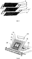
- the figure 1 shows a membrane-electrode assembly for a fuel cell.
- This assembly comprises an ion exchange membrane 1, reinforcing elements 2 and 2 ', gaskets 3 and 3', and gas diffusion layers 4 and 4 '.
- the present invention relates to the first possibility, namely the deposition of the catalysis on the membrane 1.
- the figure 2 shows a system allowing the implementation of a screen printing process.
- This system comprises a screen or frame 20, formed of a PET fabric 21, also called a mesh, whose meshes and wire diameter can be adapted to different uses.
- the fabric is coated with a photosensitive product called an emulsion on which is deposited a stencil corresponding to the pattern to be produced.
- the pattern to be produced corresponds to the central part of an ion exchange membrane, left free after installation of the reinforcements.
- the photosensitive product After being exposed to a UV lamp, the photosensitive product hardens except for the area masked by the template. The surplus is then cleaned up. Thus, the mesh then comprises open meshes 22, forming the pattern, and closed meshes 23.
- the doctor blade 27 will then force the mesh 21 to deform, bringing it into contact with the support 32.
- the catalysis is then forced when the doctor blade passes through the mesh to come and be deposited on the membrane 24.
- doctor blade also makes it possible to scrape the excess catalysis from the surface of the screen, the latter therefore being ready for a second removal.
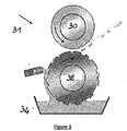
- the figure 3 illustrates another process for performing this deposition in the form of a pattern, namely a flexography process, also called “ink pad”.
- the system shown in FIG. 4 comprises a support roll 30, on which is installed the membrane 31 to be catalyzed.
- the system also comprises an ink roller 32 on which the pattern to be deposited is formed in excess thickness.
- the system further comprises a roller 33 intended to remove, after soaking in the tank, the ink present on the parts of the inking roller which do not form the pattern.
- the pattern drawn on the ink roller 32 is transferred to the membrane 31.
- the gaskets are flat gaskets deposited on the reinforcement-catalyzed membrane - reinforcement assembly.
Description
La présente invention concerne le domaine des piles à combustibles, et plus particulièrement le domaine de la fabrication et de l'assemblage de piles à combustible.The present invention relates to the field of fuel cells, and more particularly to the field of the manufacture and assembly of fuel cells.
Une pile à combustible permet la génération d'énergie électrique par une réaction électrochimique à partir d'un carburant, généralement de l'hydrogène, et d'un comburant, généralement de l'oxygène.A fuel cell allows the generation of electrical energy by an electrochemical reaction from a fuel, generally hydrogen, and an oxidizer, generally oxygen.
Une pile à combustible du type à membrane échangeuse de protons à électrolyte solide (PEMFC) comprend habituellement un empilement de cellules élémentaires, en forme de plaques, constituant des générateurs électrochimiques, chacune des cellules étant séparée des cellules adjacentes par des plaques bipolaires. Chaque cellule comprend un élément anodique et un élément cathodique, séparés par un électrolyte solide sous la forme d'une membrane échangeuse d'ions, réalisée par exemple en un matériau polymère perfluoré sulfuré.A fuel cell of the solid electrolyte proton exchange membrane (PEMFC) type usually comprises a stack of elementary cells, in the form of plates, constituting electrochemical generators, each of the cells being separated from the adjacent cells by bipolar plates. Each cell comprises an anode element and a cathode element, separated by a solid electrolyte in the form of an ion exchange membrane, made for example of a sulfurized perfluorinated polymer material.
Cet ensemble comprenant l'élément cathodique, l'élément anodique et l'électrolyte solide forme un assemblage membrane-électrode, également appelé AME. Selon une variante de réalisation habituelle, chaque plaque bipolaire assure d'un côté l'alimentation en carburant de la cellule adjacente à ce côté et de l'autre côté l'alimentation en comburant de la cellule adjacente à cet autre côté, les alimentations assurées par les plaques bipolaires se faisant en parallèle. Des couches de diffusion de gaz, par exemple réalisées en tissu de carbone, sont installées de part et d'autre des AME pour assurer la conduction électrique et l'arrivée homogène des gaz réactifs fournis via les plaques bipolaires.This assembly comprising the cathode element, the anode element and the solid electrolyte forms a membrane-electrode assembly, also called AME. According to a usual variant embodiment, each bipolar plate provides on one side the supply of fuel to the cell adjacent to this side and on the other side the supply of oxidizer to the cell adjacent to this other side, the supplies provided. by the bipolar plates being done in parallel. Gas diffusion layers, for example made of carbon fabric, are installed on either side of the MEAs to ensure electrical conduction and the homogeneous arrival of the reactive gases supplied via the bipolar plates.
Pour améliorer l'efficacité des réactions chimiques à l'anode et à la cathode, un catalyseur, généralement du platine, est utilisé dans l'empilement. Ce catalyseur peut être positionné soit sur la membrane, soit sur la couche de diffusion gazeuse.To improve the efficiency of chemical reactions at the anode and cathode, a catalyst, usually platinum, is used in the stack. This catalyst can be positioned either on the membrane or on the gas diffusion layer.
Les techniques existantes de dépôt de catalyse sur une membrane ne sont pas satisfaisantes, car la membrane étant très sensible à l'humidité, elle a tendance à se rétracter lors d'un dépôt de catalyse sur une première face, ce qui rend difficile le dépôt de catalyse sur la seconde face de la membrane. Les documents
La présente invention vise propose ainsi un procédé de dépôt de catalyse sur une membrane polymère pour pile à combustible permettant de remédier aux inconvénients précités.The present invention thus aims to provide a process for depositing catalysis on a polymer membrane for a fuel cell which makes it possible to remedy the aforementioned drawbacks.
Ainsi, l'invention concerne un procédé de fabrication d'un assemblage membrane-électrode pour pile à combustible, le procédé comprenant les étapes suivantes :
- Une première étape au cours de laquelle on dépose un renfort sur une première face d'une membrane échangeuse d'ions, la membrane étant maintenue sur un film support,
- Une deuxième étape au cours de laquelle on décolle la membrane du film support,
- Une troisième étape au cours de laquelle on dépose un renfort sur la seconde face de la membrane échangeuse d'ions, et
- Une quatrième étape au cours de laquelle on dépose un élément chimique catalyseur sur les parties laissées libres de la première et seconde faces de la membrane, la membrane étant maintenue sur sa périphérie par les éléments de renfort.
- A first step during which a reinforcement is deposited on a first face of an ion exchange membrane, the membrane being held on a support film,
- A second step during which the membrane is peeled off the support film,
- A third step during which a reinforcement is deposited on the second face of the ion exchange membrane, and
- A fourth step during which a chemical catalyst element is deposited on the parts left free of the first and second faces of the membrane, the membrane being held on its periphery by the reinforcing elements.
On précise ici que dans la suite de la description, l'expression « élément chimique catalyseur » pourra être remplacée par le terme « catalyse » par souci de simplification de l'exposé. Cet élément chimique catalyseur est préférentiellement une encre comprenant du platine, de l'eau et des solvants.It is specified here that in the remainder of the description, the expression “catalyst chemical element” may be replaced by the term “catalysis” for the sake of simplification of the description. This chemical catalyst element is preferably an ink comprising platinum, water and solvents.
Cette invention permet ainsi de remédier aux inconvénients précités en proposant un procédé dans lequel la membrane est maintenue pendant les deux étapes de dépôt de catalyse, ce qui évite qu'elle se rétracte. En effet, lors de l'étape de dépôt de la catalyse, la membrane est maintenue sur sa périphérie par les éléments de renfort qui auront été installés au préalable. En effet, les éléments de renforts sont des films polymères qui viennent se positionner de manière à prendre en sandwich la bordure de la membrane sur toute sa périphérie, et qui laissent libre une partie centrale de la membraneThis invention thus makes it possible to overcome the aforementioned drawbacks by proposing a method in which the membrane is maintained during the two stages of catalysis deposition, which prevents it from shrinking. Indeed, during the step of depositing the catalysis, the membrane is held on its periphery by the reinforcing elements which will have been installed beforehand. Indeed, the reinforcing elements are polymer films which are positioned so as to sandwich the border of the membrane over its entire periphery, and which leave a central part of the membrane free.
Ainsi, la catalyse doit ensuite être déposée non pas sur les éléments de renforts, mais uniquement sur la partie centrale de la membrane laissée libre. Pour ce faire, la quatrième étape est avantageusement mise en œuvre par un procédé permettant de réaliser un motif plutôt qu'une dépose en continue. Ainsi, cette quatrième étape est avantageusement effectuée par un procédé compris dans le groupe comprenant : la flexographie, la sérigraphie, le sprayage. Ces différents procédés seront ultérieurement détaillés à l'aide de figures.Thus, the catalysis must then be deposited not on the reinforcing elements, but only on the central part of the membrane left free. To do this, the fourth step is advantageously implemented by a method making it possible to produce a pattern rather that a continuous deposit. Thus, this fourth step is advantageously carried out by a process included in the group comprising: flexography, screen printing, spraying. These different processes will be detailed later with the help of figures.
On sait que dans un empilement de pile à combustible, il est nécessaire de positionner des joints de part et d'autre de chaque cellule élémentaire, et ce afin d'assurer une étanchéité de l'ensemble lors de l'empilement final. Dans un mode de réalisation de l'invention, les joints sont installés au préalable sur les éléments de renforts, avant l'insertion de la membrane. Un tel mode de réalisation présente deux avantages : tout d'abord, les joints étant installés avant l'insertion de la membrane, les étapes de polymérisation au four du joint ne sont pas subies par la membrane ; en outre, en cas de défaut lors de la fabrication du joint, on perd seulement un renfort, et pas la membrane. Toutefois, on a constaté que, selon le procédé employé pour la dépose de la catalyse, la présence d'une surépaisseur due aux joints pouvait être un inconvénient.It is known that in a fuel cell stack, it is necessary to position gaskets on either side of each elementary cell, in order to ensure tightness of the assembly during the final stack. In one embodiment of the invention, the seals are installed beforehand on the reinforcing elements, before the membrane is inserted. Such an embodiment has two advantages: firstly, since the seals are installed before the membrane is inserted, the oven polymerization steps of the seal are not undergone by the membrane; furthermore, in the event of a defect during the manufacture of the seal, only a reinforcement is lost, and not the membrane. However, it has been found that, depending on the method used for the removal of the catalysis, the presence of an extra thickness due to the joints could be a drawback.
Pour remédier à cela, l'invention concerne également un procédé de fabrication d'une cellule élémentaire pour pile à combustible comprenant deux plaques bipolaires identiques, entourant un assemblage membrane électrode et deux couches de diffusion gazeuse, le procédé comprenant les étapes suivantes :
- On dépose, sur une enclume de découpe, une feuille d'un matériau utilisé pour la formation de joints pour pile à combustible,
- On installe deux pinces pour positionner la feuille sur la presse de découpe,
- On effectue une première découpe avec un outil dont le gabarit dépend de la forme des plaques bipolaires de la cellule élémentaire, cette première découpe visant à délimiter la forme intérieure du joint,
- On élimine les déchets de la première découpe tout en maintenant en place le joint grâce aux pinces,
- On installe un assemblage membrane-électrode fabriquée selon un procédé selon l'invention sur le joint,
- On effectue une seconde découpe avec un outil permettant de délimiter la forme extérieure du joint, et
- On élimine les déchets de la seconde découpe.
- A sheet of a material used for forming fuel cell seals is deposited on a cutting anvil,
- We install two clamps to position the sheet on the cutting press,
- A first cut is made with a tool whose template depends on the shape of the bipolar plates of the elementary cell, this first cut aimed at delimiting the internal shape of the seal,
- Waste from the first cut is eliminated while maintaining the seal in place with the pliers,
- A membrane-electrode assembly manufactured according to a method according to the invention is installed on the seal,
- A second cut is made with a tool making it possible to delimit the external shape of the seal, and
- Waste from the second cut is eliminated.
D'autres objectifs et avantages de l'invention apparaîtront clairement dans la description qui va suivre d'un mode de réalisation préféré mais non limitatif, illustré par les figures suivantes dans lesquelles :
- la
figure 1 présente un assemblage membrane-électrode pour pile à combustible, - la
figure 2 illustre un procédé de sérigraphie mis en œuvre dans un mode de réalisation de l'invention, - la
figure 3 illustre un procédé de flexographie mis en œuvre dans un mode de réalisation de l'invention,
- the
figure 1 has a membrane-electrode assembly for a fuel cell, - the
figure 2 illustrates a screen printing process implemented in one embodiment of the invention, - the
figure 3 illustrates a flexography process implemented in one embodiment of the invention,
La
Ainsi qu'indiqué en préambule de la présente demande, dans une pile à combustible on peut choisir de déposer la catalyse sur la membrane 1 ou sur les couches de diffusion gazeuse 4 et 4'. La présente invention concerne la première possibilité, à savoir le dépôt de la catalyse sur la membrane 1.As indicated in the preamble of the present application, in a fuel cell it is possible to choose to deposit the catalysis on the membrane 1 or on the gas diffusion layers 4 and 4 '. The present invention relates to the first possibility, namely the deposition of the catalysis on the membrane 1.
Ainsi, un procédé selon l'invention se déroule de la façon suivante :
- La membrane 1 est livrée sur un film support en un matériau plastique, par exemple du PET, et on vient apposer les renforts 2 et 2' de part et d'autre de la membrane,
- La membrane 1, portant les renforts, est ensuite catalysée sur chacune des faces ; Pour ce faire, on utilise un procédé permettant d'effectuer un dépôt sous forme de motifs, tel que la sérigraphie, qui sera décrit à l'aide de la
figure 3 , ou la flexographie qui sera décrit à l'aide de la figure 4, - Les joints 3 et 3' sont ensuite installés en utilisant un procédé selon l'invention,
- Enfin, les couches de diffusion gazeuse 4 et 4' sont installées.
- The membrane 1 is delivered on a support film made of a plastic material, for example PET, and the
reinforcements 2 and 2 'are affixed on either side of the membrane, - The membrane 1, carrying the reinforcements, is then catalyzed on each of the faces; To do this, a method is used which makes it possible to carry out a deposition in the form of patterns, such as screen printing, which will be described using the
figure 3 , or flexography which will be described with the aid of FIG. 4, -
Seals 3 and 3 'are then installed using a method according to the invention, - Finally, the gas diffusion layers 4 and 4 'are installed.
La
Pour la création du motif à réaliser, le tissu est enduit d'un produit photosensible appelé émulsion sur lequel est déposé un chablon correspondant au motif à réaliser. Dans le cas présent, le motif à réaliser correspond à la partie centrale d'une membrane échangeuse d'ions, laissée libre après l'installation des renforts.To create the pattern to be produced, the fabric is coated with a photosensitive product called an emulsion on which is deposited a stencil corresponding to the pattern to be produced. In the present case, the pattern to be produced corresponds to the central part of an ion exchange membrane, left free after installation of the reinforcements.
Après avoir subi une exposition à une lampe UV, le produit photosensible durcit à l'exception de la zone masquée par le chablon. Le surplus est ensuite nettoyé. Ainsi, le treillis comporte alors des mailles ouvertes 22, formant le motif, et des mailles obturées 23.After being exposed to a UV lamp, the photosensitive product hardens except for the area masked by the template. The surplus is then cleaned up. Thus, the mesh then comprises
Une fois ce cadre, ou écran, fabriqué, il est alors possible d'effectuer un dépôt de catalyse par sérigraphie. Pour ce faire, la membrane 24, catalysée sur une face, et portant les renforts, est installée sur le support 25, la face non catalysée étant installée vers le haut. L'écran 20 est alors positionné sur le support 25, au-dessus de la membrane 24. Une quantité suffisante de catalyse 26 est alors déposée sur le cadre, et étalé de façon régulière sur le motif mais sans appuyer trop fort pour éviter de lui faire traverser le treillis. Cette opération est appelée « le nappage ».Once this frame, or screen, has been manufactured, it is then possible to carry out a deposition of catalysis by screen printing. To do this, the
Puis, une racle 27 formée d'un profil de polyuréthane ou métallique dont la dureté et la raideur peuvent être adaptées, est passée tout le long du profil avec un angle variable proche de 45°. On précise ici que le cadre 20 est installé un peu au-dessus du support 25 de manière à éviter un contact entre les deux avant le passage de la racle.Then, a
La racle 27 va alors forcer le treillis 21 à se déformer, l'amenant au contact du support 32. La catalyse est ensuite forcée au passage de la racle à traverser le treillis pour venir se déposer sur la membrane 24.The
La racle permet aussi de racler le surplus de catalyse à la surface de l'écran, celle-ci étant dès lors près pour une deuxième dépose.The doctor blade also makes it possible to scrape the excess catalysis from the surface of the screen, the latter therefore being ready for a second removal.
La
Ainsi, lors du contact entre le rouleau de support 30 et le rouleau encreur 32, le motif dessiné sur le rouleau encreur 32 est transféré sur la membrane 31.Thus, upon contact between the
On constate, dans la description de procédés tels que la sérigraphie ou la flexographie, que la présence d'une surépaisseur sur la membrane pourrait poser des problèmes pour le dépôt de la catalyse. Ainsi, il apparaît judicieux d'effectuer le dépôt de catalyse avant l'installation des joints de chaque côté de la membrane.It is noted, in the description of processes such as screen printing or flexography, that the presence of an extra thickness on the membrane could pose problems for the deposition of the catalysis. Thus, it appears judicious to carry out the catalysis deposit before installing the seals on each side of the membrane.
Ainsi, dans un mode de réalisation particulier, les joints sont des joints plats déposés sur l'ensemble renfort-membrane catalysée - renfort. Nous allons décrire ci-après, un exemple de procédé de découpe et de dépôt de joints pouvant être mis en œuvre à cet effet.Thus, in a particular embodiment, the gaskets are flat gaskets deposited on the reinforcement-catalyzed membrane - reinforcement assembly. We will describe below an example of a process for cutting and depositing seals that can be implemented for this purpose.
Claims (6)
- Method for manufacturing a membrane-electrode assembly for a fuel cell, the method comprising the following steps:- A first step during which a reinforcement (2) is deposited on a first face of an ion-exchanging membrane (1), the membrane being held on a support film,- A second step during which the membrane is unglued from the support film,- A third step during which a reinforcement (2') is deposited on the second face of the ion-exchanging membrane, and- A fourth step during which a chemical catalyst element is deposited on the parts left free of the first and second faces of the membrane, the membrane being held on its periphery by the reinforcing elements (2,2').
- Deposition method according to Claim 1, wherein the chemical catalyst element is an ink comprising platinum, water and solvents.
- Deposition method according to Claim 1 or 2, wherein the support film is a film made of plastic material, for example of PET.
- Deposition method according to one of the preceding claims, wherein the fourth step is performed by a method included in the group comprising: flexography, screenprinting and spraying.
- Method according to one of the preceding claims, wherein the seals (3, 3') are present on the reinforcements.
- Method for manufacturing an elementary cell for a fuel cell comprising two identical bipolar plates, surrounding a membrane-electrode assembly and two gas diffusion layers, the method comprising the following steps:- A sheet of a material used for forming seals for a fuel cell is placed on a cutting anvil,- Two clamps are installed for positioning the sheet on the cutting press,- A first cutting is performed with a tool whose template depends on the form of the bipolar plates of the elementary cell, the purpose of this first cutting being to delimit the internal form of the seal,- The waste from the first cutting is eliminated while keeping the seal in place by virtue of the clamps,- A membrane-electrode assembly manufactured according to a method according to one of Claims 1 to 5 is installed on the seal,- A second cutting is performed with a tool making it possible to delimit the outer form of the seal,- The waste from the second cutting is eliminated.
Applications Claiming Priority (2)
| Application Number | Priority Date | Filing Date | Title |
|---|---|---|---|
| FR1662300A FR3060210A1 (en) | 2016-12-12 | 2016-12-12 | PROCESS FOR MANUFACTURING MEMBRANE-ELECTRODE ASSEMBLY FOR FUEL CELL |
| PCT/FR2017/053465 WO2018109334A1 (en) | 2016-12-12 | 2017-12-08 | Method for producing a membrane electrode assembly for a fuel cell |
Publications (2)
| Publication Number | Publication Date |
|---|---|
| EP3552265A1 EP3552265A1 (en) | 2019-10-16 |
| EP3552265B1 true EP3552265B1 (en) | 2021-02-03 |
Family
ID=57965976
Family Applications (1)
| Application Number | Title | Priority Date | Filing Date |
|---|---|---|---|
| EP17821695.8A Active EP3552265B1 (en) | 2016-12-12 | 2017-12-08 | Process of manufacturing a membrane-electrode assembly for a fuel cell |
Country Status (5)
| Country | Link |
|---|---|
| US (1) | US11271224B2 (en) |
| EP (1) | EP3552265B1 (en) |
| CN (1) | CN110088961A (en) |
| FR (1) | FR3060210A1 (en) |
| WO (1) | WO2018109334A1 (en) |
Families Citing this family (3)
| Publication number | Priority date | Publication date | Assignee | Title |
|---|---|---|---|---|
| FR3060209A1 (en) | 2016-12-12 | 2018-06-15 | Compagnie Generale Des Etablissements Michelin | PROCESS FOR MANUFACTURING MEMBRANE-ELECTRODE ASSEMBLY FOR FUEL CELL |
| CN112993350A (en) * | 2019-12-14 | 2021-06-18 | 中国科学院大连化学物理研究所 | Continuous batch production method and device for fuel cell membrane electrode |
| SE2050394A1 (en) * | 2020-04-07 | 2021-10-08 | Powercell Sweden Ab | Cutting device for membrane electrode assembly |
Family Cites Families (14)
| Publication number | Priority date | Publication date | Assignee | Title |
|---|---|---|---|---|
| CN1558461A (en) | 2000-07-06 | 2004-12-29 | ���µ�����ҵ��ʽ���� | Method for producing an electrolyte film-electrode joint |
| KR100443107B1 (en) | 2001-03-15 | 2004-08-04 | 마쯔시다덴기산교 가부시키가이샤 | Method of manufacturing elect rolytic film electrode connection body for fuel cell |
| US8097112B2 (en) * | 2005-06-20 | 2012-01-17 | Panasonic Corporation | Method for manufacturing membrane-electrode assembly |
| CN101268575B (en) * | 2005-09-15 | 2010-05-26 | 松下电器产业株式会社 | Membrane-membrane stiffening member union, membrane-catalyst layer union, membrane-electrode union, and polymer electrolyte type fuel cell |
| JP4959253B2 (en) * | 2006-08-17 | 2012-06-20 | 本田技研工業株式会社 | MANUFACTURING SHEET FOR FUEL CELL MEMBRANE ELECTRODE STRUCTURE AND METHOD FOR PRODUCING FUEL CELL MEMBRANE ELECTRODE STRUCTURE |
| JP2009193860A (en) * | 2008-02-15 | 2009-08-27 | Asahi Glass Co Ltd | Membrane-electrode assembly for polymer electrolyte fuel cell and method of manufacturing the same |
| JP5366469B2 (en) | 2008-08-04 | 2013-12-11 | 本田技研工業株式会社 | Electrolyte membrane / electrode structure |
| FR2995145B1 (en) | 2012-09-03 | 2014-12-26 | Commissariat Energie Atomique | METHOD FOR MANUFACTURING A FUEL CELL INCLUDING ELECTRODE / MEMBRANE ASSEMBLY |
| EP2842620A1 (en) * | 2013-08-26 | 2015-03-04 | Agfa-Gevaert | A method for preparing a composite membrane |
| FR3036537A1 (en) | 2015-05-22 | 2016-11-25 | Michelin & Cie | FUEL CELL |
| FR3036539A1 (en) | 2015-05-22 | 2016-11-25 | Michelin & Cie | PROCESS FOR PROCESSING A BIPOLAR PLATE FOR A FUEL CELL |
| FR3039931B1 (en) | 2015-08-07 | 2017-08-25 | Michelin & Cie | STACK FOR THE MANUFACTURE OF BIPOLAR PLATES FOR FUEL CELLS |
| FR3045949A1 (en) | 2015-12-16 | 2017-06-23 | Michelin & Cie | PROCESS FOR MANUFACTURING FUEL CELL WITH SERIGRAPHY SEAL |
| FR3060209A1 (en) | 2016-12-12 | 2018-06-15 | Compagnie Generale Des Etablissements Michelin | PROCESS FOR MANUFACTURING MEMBRANE-ELECTRODE ASSEMBLY FOR FUEL CELL |
-
2016
- 2016-12-12 FR FR1662300A patent/FR3060210A1/en not_active Withdrawn
-
2017
- 2017-12-08 EP EP17821695.8A patent/EP3552265B1/en active Active
- 2017-12-08 WO PCT/FR2017/053465 patent/WO2018109334A1/en active Application Filing
- 2017-12-08 CN CN201780076217.2A patent/CN110088961A/en active Pending
- 2017-12-08 US US16/468,866 patent/US11271224B2/en active Active
Non-Patent Citations (1)
| Title |
|---|
| None * |
Also Published As
| Publication number | Publication date |
|---|---|
| WO2018109334A1 (en) | 2018-06-21 |
| FR3060210A1 (en) | 2018-06-15 |
| US11271224B2 (en) | 2022-03-08 |
| CN110088961A (en) | 2019-08-02 |
| US20200075970A1 (en) | 2020-03-05 |
| EP3552265A1 (en) | 2019-10-16 |
Similar Documents
| Publication | Publication Date | Title |
|---|---|---|
| EP3391444B1 (en) | Method for producing a fuel cell with a screen-printed seal | |
| EP3552265B1 (en) | Process of manufacturing a membrane-electrode assembly for a fuel cell | |
| EP3552264B1 (en) | Process of manufacturing a membrane-electrode assembly for a fuel cell | |
| EP3560019B1 (en) | Process of manufacturing a membrane-electrode assembly for a fuel cell | |
| FR2995145A1 (en) | METHOD FOR MANUFACTURING A FUEL CELL INCLUDING ELECTRODE / MEMBRANE ASSEMBLY | |
| CA2787317A1 (en) | Five-layer membrane electrode assembly with attached border and method of making same | |
| EP2782175B1 (en) | Method for manufacturing a membrane-electrode assembly | |
| WO2010079184A1 (en) | Method for making a high-temperature electrolyser or a high-temperature fuel cell including a stack of elementary cells | |
| EP3560018B1 (en) | Process of manufacturing an membrane-electrode assembly for a fuel cell | |
| WO2020115450A1 (en) | Method for producing a membrane electrode assembly for a fuel cell | |
| EP3836267B1 (en) | Process of manufacturing a component constituting an interconnect of electrolyzer soec or a fuel cell sofc | |
| EP2867947A1 (en) | Method for manufacturing an electrode/proton-exchange membrane assembly | |
| EP3891827A1 (en) | Method for producing a membrane electrode assembly for a fuel cell | |
| FR2846797A1 (en) | Basic module for a miniature fuel cell incorporates a porous gas-permeable substrate with a relief holding a three layer stack forming the anode, electrolyte and cathode | |
| EP4203117A1 (en) | Seal for electrochemical reactor and method for manufacturing same | |
| EP3843185B1 (en) | Method and device for manufacturing an active layer membrane assembly of a fuel cell or an electrolyser | |
| CA3062030A1 (en) | Fuel cell assembly process | |
| WO2018109332A1 (en) | Method for producing an elementary cell for a fuel cell | |
| EP4203116A1 (en) | Method for manufacturing a flow guide for an electrochemical reactor | |
| FR3131458A1 (en) | Method for manufacturing a flow guide for an electrochemical reactor | |
| FR3065903A1 (en) | METHOD FOR ASSEMBLING MEMBRANE / ELECTRODES |
Legal Events
| Date | Code | Title | Description |
|---|---|---|---|
| STAA | Information on the status of an ep patent application or granted ep patent |
Free format text: STATUS: UNKNOWN |
|
| STAA | Information on the status of an ep patent application or granted ep patent |
Free format text: STATUS: THE INTERNATIONAL PUBLICATION HAS BEEN MADE |
|
| PUAI | Public reference made under article 153(3) epc to a published international application that has entered the european phase |
Free format text: ORIGINAL CODE: 0009012 |
|
| STAA | Information on the status of an ep patent application or granted ep patent |
Free format text: STATUS: REQUEST FOR EXAMINATION WAS MADE |
|
| 17P | Request for examination filed |
Effective date: 20190712 |
|
| AK | Designated contracting states |
Kind code of ref document: A1 Designated state(s): AL AT BE BG CH CY CZ DE DK EE ES FI FR GB GR HR HU IE IS IT LI LT LU LV MC MK MT NL NO PL PT RO RS SE SI SK SM TR |
|
| AX | Request for extension of the european patent |
Extension state: BA ME |
|
| DAV | Request for validation of the european patent (deleted) | ||
| DAX | Request for extension of the european patent (deleted) | ||
| GRAP | Despatch of communication of intention to grant a patent |
Free format text: ORIGINAL CODE: EPIDOSNIGR1 |
|
| STAA | Information on the status of an ep patent application or granted ep patent |
Free format text: STATUS: GRANT OF PATENT IS INTENDED |
|
| INTG | Intention to grant announced |
Effective date: 20200806 |
|
| GRAS | Grant fee paid |
Free format text: ORIGINAL CODE: EPIDOSNIGR3 |
|
| GRAA | (expected) grant |
Free format text: ORIGINAL CODE: 0009210 |
|
| STAA | Information on the status of an ep patent application or granted ep patent |
Free format text: STATUS: THE PATENT HAS BEEN GRANTED |
|
| AK | Designated contracting states |
Kind code of ref document: B1 Designated state(s): AL AT BE BG CH CY CZ DE DK EE ES FI FR GB GR HR HU IE IS IT LI LT LU LV MC MK MT NL NO PL PT RO RS SE SI SK SM TR |
|
| REG | Reference to a national code |
Ref country code: GB Ref legal event code: FG4D Free format text: NOT ENGLISH |
|
| REG | Reference to a national code |
Ref country code: AT Ref legal event code: REF Ref document number: 1359893 Country of ref document: AT Kind code of ref document: T Effective date: 20210215 Ref country code: CH Ref legal event code: EP |
|
| REG | Reference to a national code |
Ref country code: DE Ref legal event code: R096 Ref document number: 602017032371 Country of ref document: DE |
|
| REG | Reference to a national code |
Ref country code: IE Ref legal event code: FG4D Free format text: LANGUAGE OF EP DOCUMENT: FRENCH |
|
| REG | Reference to a national code |
Ref country code: NL Ref legal event code: MP Effective date: 20210203 |
|
| REG | Reference to a national code |
Ref country code: LT Ref legal event code: MG9D |
|
| REG | Reference to a national code |
Ref country code: AT Ref legal event code: MK05 Ref document number: 1359893 Country of ref document: AT Kind code of ref document: T Effective date: 20210203 |
|
| PG25 | Lapsed in a contracting state [announced via postgrant information from national office to epo] |
Ref country code: LT Free format text: LAPSE BECAUSE OF FAILURE TO SUBMIT A TRANSLATION OF THE DESCRIPTION OR TO PAY THE FEE WITHIN THE PRESCRIBED TIME-LIMIT Effective date: 20210203 Ref country code: BG Free format text: LAPSE BECAUSE OF FAILURE TO SUBMIT A TRANSLATION OF THE DESCRIPTION OR TO PAY THE FEE WITHIN THE PRESCRIBED TIME-LIMIT Effective date: 20210503 Ref country code: PT Free format text: LAPSE BECAUSE OF FAILURE TO SUBMIT A TRANSLATION OF THE DESCRIPTION OR TO PAY THE FEE WITHIN THE PRESCRIBED TIME-LIMIT Effective date: 20210604 Ref country code: NO Free format text: LAPSE BECAUSE OF FAILURE TO SUBMIT A TRANSLATION OF THE DESCRIPTION OR TO PAY THE FEE WITHIN THE PRESCRIBED TIME-LIMIT Effective date: 20210503 Ref country code: GR Free format text: LAPSE BECAUSE OF FAILURE TO SUBMIT A TRANSLATION OF THE DESCRIPTION OR TO PAY THE FEE WITHIN THE PRESCRIBED TIME-LIMIT Effective date: 20210504 Ref country code: HR Free format text: LAPSE BECAUSE OF FAILURE TO SUBMIT A TRANSLATION OF THE DESCRIPTION OR TO PAY THE FEE WITHIN THE PRESCRIBED TIME-LIMIT Effective date: 20210203 Ref country code: FI Free format text: LAPSE BECAUSE OF FAILURE TO SUBMIT A TRANSLATION OF THE DESCRIPTION OR TO PAY THE FEE WITHIN THE PRESCRIBED TIME-LIMIT Effective date: 20210203 |
|
| PG25 | Lapsed in a contracting state [announced via postgrant information from national office to epo] |
Ref country code: AT Free format text: LAPSE BECAUSE OF FAILURE TO SUBMIT A TRANSLATION OF THE DESCRIPTION OR TO PAY THE FEE WITHIN THE PRESCRIBED TIME-LIMIT Effective date: 20210203 Ref country code: RS Free format text: LAPSE BECAUSE OF FAILURE TO SUBMIT A TRANSLATION OF THE DESCRIPTION OR TO PAY THE FEE WITHIN THE PRESCRIBED TIME-LIMIT Effective date: 20210203 Ref country code: NL Free format text: LAPSE BECAUSE OF FAILURE TO SUBMIT A TRANSLATION OF THE DESCRIPTION OR TO PAY THE FEE WITHIN THE PRESCRIBED TIME-LIMIT Effective date: 20210203 Ref country code: LV Free format text: LAPSE BECAUSE OF FAILURE TO SUBMIT A TRANSLATION OF THE DESCRIPTION OR TO PAY THE FEE WITHIN THE PRESCRIBED TIME-LIMIT Effective date: 20210203 Ref country code: PL Free format text: LAPSE BECAUSE OF FAILURE TO SUBMIT A TRANSLATION OF THE DESCRIPTION OR TO PAY THE FEE WITHIN THE PRESCRIBED TIME-LIMIT Effective date: 20210203 Ref country code: SE Free format text: LAPSE BECAUSE OF FAILURE TO SUBMIT A TRANSLATION OF THE DESCRIPTION OR TO PAY THE FEE WITHIN THE PRESCRIBED TIME-LIMIT Effective date: 20210203 |
|
| PG25 | Lapsed in a contracting state [announced via postgrant information from national office to epo] |
Ref country code: IS Free format text: LAPSE BECAUSE OF FAILURE TO SUBMIT A TRANSLATION OF THE DESCRIPTION OR TO PAY THE FEE WITHIN THE PRESCRIBED TIME-LIMIT Effective date: 20210603 |
|
| PG25 | Lapsed in a contracting state [announced via postgrant information from national office to epo] |
Ref country code: CZ Free format text: LAPSE BECAUSE OF FAILURE TO SUBMIT A TRANSLATION OF THE DESCRIPTION OR TO PAY THE FEE WITHIN THE PRESCRIBED TIME-LIMIT Effective date: 20210203 Ref country code: EE Free format text: LAPSE BECAUSE OF FAILURE TO SUBMIT A TRANSLATION OF THE DESCRIPTION OR TO PAY THE FEE WITHIN THE PRESCRIBED TIME-LIMIT Effective date: 20210203 Ref country code: SM Free format text: LAPSE BECAUSE OF FAILURE TO SUBMIT A TRANSLATION OF THE DESCRIPTION OR TO PAY THE FEE WITHIN THE PRESCRIBED TIME-LIMIT Effective date: 20210203 |
|
| REG | Reference to a national code |
Ref country code: DE Ref legal event code: R097 Ref document number: 602017032371 Country of ref document: DE |
|
| PG25 | Lapsed in a contracting state [announced via postgrant information from national office to epo] |
Ref country code: DK Free format text: LAPSE BECAUSE OF FAILURE TO SUBMIT A TRANSLATION OF THE DESCRIPTION OR TO PAY THE FEE WITHIN THE PRESCRIBED TIME-LIMIT Effective date: 20210203 Ref country code: SK Free format text: LAPSE BECAUSE OF FAILURE TO SUBMIT A TRANSLATION OF THE DESCRIPTION OR TO PAY THE FEE WITHIN THE PRESCRIBED TIME-LIMIT Effective date: 20210203 Ref country code: RO Free format text: LAPSE BECAUSE OF FAILURE TO SUBMIT A TRANSLATION OF THE DESCRIPTION OR TO PAY THE FEE WITHIN THE PRESCRIBED TIME-LIMIT Effective date: 20210203 |
|
| PLBE | No opposition filed within time limit |
Free format text: ORIGINAL CODE: 0009261 |
|
| STAA | Information on the status of an ep patent application or granted ep patent |
Free format text: STATUS: NO OPPOSITION FILED WITHIN TIME LIMIT |
|
| 26N | No opposition filed |
Effective date: 20211104 |
|
| PG25 | Lapsed in a contracting state [announced via postgrant information from national office to epo] |
Ref country code: ES Free format text: LAPSE BECAUSE OF FAILURE TO SUBMIT A TRANSLATION OF THE DESCRIPTION OR TO PAY THE FEE WITHIN THE PRESCRIBED TIME-LIMIT Effective date: 20210203 Ref country code: AL Free format text: LAPSE BECAUSE OF FAILURE TO SUBMIT A TRANSLATION OF THE DESCRIPTION OR TO PAY THE FEE WITHIN THE PRESCRIBED TIME-LIMIT Effective date: 20210203 |
|
| PG25 | Lapsed in a contracting state [announced via postgrant information from national office to epo] |
Ref country code: SI Free format text: LAPSE BECAUSE OF FAILURE TO SUBMIT A TRANSLATION OF THE DESCRIPTION OR TO PAY THE FEE WITHIN THE PRESCRIBED TIME-LIMIT Effective date: 20210203 |
|
| PG25 | Lapsed in a contracting state [announced via postgrant information from national office to epo] |
Ref country code: IS Free format text: LAPSE BECAUSE OF FAILURE TO SUBMIT A TRANSLATION OF THE DESCRIPTION OR TO PAY THE FEE WITHIN THE PRESCRIBED TIME-LIMIT Effective date: 20210603 |
|
| PG25 | Lapsed in a contracting state [announced via postgrant information from national office to epo] |
Ref country code: MC Free format text: LAPSE BECAUSE OF FAILURE TO SUBMIT A TRANSLATION OF THE DESCRIPTION OR TO PAY THE FEE WITHIN THE PRESCRIBED TIME-LIMIT Effective date: 20210203 |
|
| REG | Reference to a national code |
Ref country code: CH Ref legal event code: PL |
|
| GBPC | Gb: european patent ceased through non-payment of renewal fee |
Effective date: 20211208 |
|
| REG | Reference to a national code |
Ref country code: BE Ref legal event code: MM Effective date: 20211231 |
|
| PG25 | Lapsed in a contracting state [announced via postgrant information from national office to epo] |
Ref country code: LU Free format text: LAPSE BECAUSE OF NON-PAYMENT OF DUE FEES Effective date: 20211208 Ref country code: IE Free format text: LAPSE BECAUSE OF NON-PAYMENT OF DUE FEES Effective date: 20211208 Ref country code: GB Free format text: LAPSE BECAUSE OF NON-PAYMENT OF DUE FEES Effective date: 20211208 |
|
| PG25 | Lapsed in a contracting state [announced via postgrant information from national office to epo] |
Ref country code: BE Free format text: LAPSE BECAUSE OF NON-PAYMENT OF DUE FEES Effective date: 20211231 |
|
| PG25 | Lapsed in a contracting state [announced via postgrant information from national office to epo] |
Ref country code: LI Free format text: LAPSE BECAUSE OF NON-PAYMENT OF DUE FEES Effective date: 20211231 Ref country code: CH Free format text: LAPSE BECAUSE OF NON-PAYMENT OF DUE FEES Effective date: 20211231 |
|
| PG25 | Lapsed in a contracting state [announced via postgrant information from national office to epo] |
Ref country code: CY Free format text: LAPSE BECAUSE OF FAILURE TO SUBMIT A TRANSLATION OF THE DESCRIPTION OR TO PAY THE FEE WITHIN THE PRESCRIBED TIME-LIMIT Effective date: 20210203 |
|
| PG25 | Lapsed in a contracting state [announced via postgrant information from national office to epo] |
Ref country code: HU Free format text: LAPSE BECAUSE OF FAILURE TO SUBMIT A TRANSLATION OF THE DESCRIPTION OR TO PAY THE FEE WITHIN THE PRESCRIBED TIME-LIMIT; INVALID AB INITIO Effective date: 20171208 |
|
| PGFP | Annual fee paid to national office [announced via postgrant information from national office to epo] |
Ref country code: IT Payment date: 20231228 Year of fee payment: 7 Ref country code: FR Payment date: 20231222 Year of fee payment: 7 Ref country code: DE Payment date: 20231214 Year of fee payment: 7 |