EP3552262B1 - Fuel cell - Google Patents
Fuel cell Download PDFInfo
- Publication number
- EP3552262B1 EP3552262B1 EP17805216.3A EP17805216A EP3552262B1 EP 3552262 B1 EP3552262 B1 EP 3552262B1 EP 17805216 A EP17805216 A EP 17805216A EP 3552262 B1 EP3552262 B1 EP 3552262B1
- Authority
- EP
- European Patent Office
- Prior art keywords
- membrane
- fuel cell
- electrode
- region
- edge
- Prior art date
- Legal status (The legal status is an assumption and is not a legal conclusion. Google has not performed a legal analysis and makes no representation as to the accuracy of the status listed.)
- Active
Links
- 239000000446 fuel Substances 0.000 title claims description 85
- 239000012528 membrane Substances 0.000 claims description 95
- 238000009826 distribution Methods 0.000 claims description 77
- XLYOFNOQVPJJNP-UHFFFAOYSA-N water Substances O XLYOFNOQVPJJNP-UHFFFAOYSA-N 0.000 claims description 25
- 239000007800 oxidant agent Substances 0.000 claims description 22
- 230000001590 oxidative effect Effects 0.000 claims 2
- 239000001257 hydrogen Substances 0.000 description 7
- 229910052739 hydrogen Inorganic materials 0.000 description 7
- 238000006243 chemical reaction Methods 0.000 description 6
- 239000002826 coolant Substances 0.000 description 5
- 238000009792 diffusion process Methods 0.000 description 5
- 238000007599 discharging Methods 0.000 description 5
- QVGXLLKOCUKJST-UHFFFAOYSA-N atomic oxygen Chemical compound [O] QVGXLLKOCUKJST-UHFFFAOYSA-N 0.000 description 4
- 239000001301 oxygen Substances 0.000 description 4
- 229910052760 oxygen Inorganic materials 0.000 description 4
- UFHFLCQGNIYNRP-UHFFFAOYSA-N Hydrogen Chemical compound [H][H] UFHFLCQGNIYNRP-UHFFFAOYSA-N 0.000 description 3
- OKKJLVBELUTLKV-UHFFFAOYSA-N Methanol Chemical compound OC OKKJLVBELUTLKV-UHFFFAOYSA-N 0.000 description 3
- 239000003570 air Substances 0.000 description 3
- 150000002431 hydrogen Chemical class 0.000 description 3
- -1 hydrogen ions Chemical class 0.000 description 2
- VNWKTOKETHGBQD-UHFFFAOYSA-N methane Chemical compound C VNWKTOKETHGBQD-UHFFFAOYSA-N 0.000 description 2
- 238000009827 uniform distribution Methods 0.000 description 2
- 238000010521 absorption reaction Methods 0.000 description 1
- 239000012080 ambient air Substances 0.000 description 1
- 239000000110 cooling liquid Substances 0.000 description 1
- 238000001035 drying Methods 0.000 description 1
- 239000007789 gas Substances 0.000 description 1
- 150000002500 ions Chemical class 0.000 description 1
- 238000000034 method Methods 0.000 description 1
- 238000012986 modification Methods 0.000 description 1
- 230000004048 modification Effects 0.000 description 1
- 239000005518 polymer electrolyte Substances 0.000 description 1
Images

Classifications
-
- H—ELECTRICITY
- H01—ELECTRIC ELEMENTS
- H01M—PROCESSES OR MEANS, e.g. BATTERIES, FOR THE DIRECT CONVERSION OF CHEMICAL ENERGY INTO ELECTRICAL ENERGY
- H01M8/00—Fuel cells; Manufacture thereof
- H01M8/02—Details
- H01M8/0202—Collectors; Separators, e.g. bipolar separators; Interconnectors
- H01M8/0258—Collectors; Separators, e.g. bipolar separators; Interconnectors characterised by the configuration of channels, e.g. by the flow field of the reactant or coolant
-
- H—ELECTRICITY
- H01—ELECTRIC ELEMENTS
- H01M—PROCESSES OR MEANS, e.g. BATTERIES, FOR THE DIRECT CONVERSION OF CHEMICAL ENERGY INTO ELECTRICAL ENERGY
- H01M8/00—Fuel cells; Manufacture thereof
- H01M8/04—Auxiliary arrangements, e.g. for control of pressure or for circulation of fluids
- H01M8/04082—Arrangements for control of reactant parameters, e.g. pressure or concentration
- H01M8/04089—Arrangements for control of reactant parameters, e.g. pressure or concentration of gaseous reactants
- H01M8/04119—Arrangements for control of reactant parameters, e.g. pressure or concentration of gaseous reactants with simultaneous supply or evacuation of electrolyte; Humidifying or dehumidifying
- H01M8/04126—Humidifying
-
- H—ELECTRICITY
- H01—ELECTRIC ELEMENTS
- H01M—PROCESSES OR MEANS, e.g. BATTERIES, FOR THE DIRECT CONVERSION OF CHEMICAL ENERGY INTO ELECTRICAL ENERGY
- H01M8/00—Fuel cells; Manufacture thereof
- H01M8/24—Grouping of fuel cells, e.g. stacking of fuel cells
- H01M8/2465—Details of groupings of fuel cells
- H01M8/2483—Details of groupings of fuel cells characterised by internal manifolds
-
- H—ELECTRICITY
- H01—ELECTRIC ELEMENTS
- H01M—PROCESSES OR MEANS, e.g. BATTERIES, FOR THE DIRECT CONVERSION OF CHEMICAL ENERGY INTO ELECTRICAL ENERGY
- H01M8/00—Fuel cells; Manufacture thereof
- H01M8/10—Fuel cells with solid electrolytes
- H01M2008/1095—Fuel cells with polymeric electrolytes
-
- H—ELECTRICITY
- H01—ELECTRIC ELEMENTS
- H01M—PROCESSES OR MEANS, e.g. BATTERIES, FOR THE DIRECT CONVERSION OF CHEMICAL ENERGY INTO ELECTRICAL ENERGY
- H01M2250/00—Fuel cells for particular applications; Specific features of fuel cell system
- H01M2250/20—Fuel cells in motive systems, e.g. vehicle, ship, plane
-
- Y—GENERAL TAGGING OF NEW TECHNOLOGICAL DEVELOPMENTS; GENERAL TAGGING OF CROSS-SECTIONAL TECHNOLOGIES SPANNING OVER SEVERAL SECTIONS OF THE IPC; TECHNICAL SUBJECTS COVERED BY FORMER USPC CROSS-REFERENCE ART COLLECTIONS [XRACs] AND DIGESTS
- Y02—TECHNOLOGIES OR APPLICATIONS FOR MITIGATION OR ADAPTATION AGAINST CLIMATE CHANGE
- Y02E—REDUCTION OF GREENHOUSE GAS [GHG] EMISSIONS, RELATED TO ENERGY GENERATION, TRANSMISSION OR DISTRIBUTION
- Y02E60/00—Enabling technologies; Technologies with a potential or indirect contribution to GHG emissions mitigation
- Y02E60/30—Hydrogen technology
- Y02E60/50—Fuel cells
-
- Y—GENERAL TAGGING OF NEW TECHNOLOGICAL DEVELOPMENTS; GENERAL TAGGING OF CROSS-SECTIONAL TECHNOLOGIES SPANNING OVER SEVERAL SECTIONS OF THE IPC; TECHNICAL SUBJECTS COVERED BY FORMER USPC CROSS-REFERENCE ART COLLECTIONS [XRACs] AND DIGESTS
- Y02—TECHNOLOGIES OR APPLICATIONS FOR MITIGATION OR ADAPTATION AGAINST CLIMATE CHANGE
- Y02T—CLIMATE CHANGE MITIGATION TECHNOLOGIES RELATED TO TRANSPORTATION
- Y02T90/00—Enabling technologies or technologies with a potential or indirect contribution to GHG emissions mitigation
- Y02T90/40—Application of hydrogen technology to transportation, e.g. using fuel cells
Definitions
- the invention relates to a fuel cell which comprises at least one membrane-electrode unit with a first electrode and a second electrode, which are separated from one another by a membrane, and at least two bipolar plates, which adjoin the membrane-electrode unit on both sides.
- the bipolar plates are broken through by a first supply channel for supplying a fuel and by a second supply channel for supplying an oxidizing agent.
- a fuel cell is a galvanic cell that converts the chemical reaction energy of a continuously supplied fuel and an oxidizing agent into electrical energy.
- a fuel cell is therefore an electrochemical energy converter.
- hydrogen (H2) and oxygen (O2) in particular are converted into water (H2O), electrical energy and heat.
- H2O water
- electrical energy and heat but there are also known fuel cells which work with methanol or methane.
- Proton exchange membrane fuel cells have a centrally arranged membrane that is permeable to protons, i.e. hydrogen ions.
- the oxidizing agent in particular atmospheric oxygen, is thereby spatially separated from the fuel, in particular hydrogen.
- Proton exchange membrane fuel cells also have an anode and a cathode.
- the fuel is fed to the anode of the fuel cell and is catalytically oxidized to protons, releasing electrons.
- the protons pass through the membrane to the cathode.
- the released electrons are derived from the fuel cell and flow to the cathode via an external circuit.
- the oxidizing agent is fed to the fuel cell's cathode and it reacts to water by absorbing electrons from the external circuit and protons that have passed through the membrane to the cathode. The resulting water is drained from the fuel cell.
- the gross response is: O 2 + 4H + + 4e - ⁇ 2H 2 O
- a voltage is applied between the anode and the cathode of the fuel cell.
- several fuel cells can be mechanically arranged one behind the other to form a fuel cell stack and electrically connected in series.
- Distributor plates which are also referred to as bipolar plates, are provided for uniform distribution of the fuel on the anode and for uniform distribution of the oxidizing agent on the cathode.
- the bipolar plates have, for example, channel-like structures for distributing the fuel and the oxidizing agent.
- the bipolar plates can also have structures for conducting a cooling liquid through the fuel cell in order to dissipate heat.
- a fuel cell is known with a membrane electrode unit arranged between two bipolar plates.
- the bipolar plates each have distribution structures for distributing the reaction gases to the electrodes.
- the DE 11 2013 001654 T5 discloses another such fuel cell.
- the membrane of the membrane electrode unit must be kept moist so that the fuel cell works properly. Particularly when the fuel cell is operated at a relatively high temperature, the membrane can dry out due to the increased water absorption capacity of the air, which can impair the function of the fuel cell.
- a fuel cell which comprises at least one membrane electrode unit with a first electrode and a second electrode, which are separated from one another by a membrane, and at least two bipolar plates which are connected to the membrane electrode unit on both sides.
- the bipolar plates are broken through by a first supply channel for supplying a fuel and by a second supply channel for supplying an oxidizing agent.
- the first electrode is also called the anode and the second electrode is also called the cathode.
- the fuel is, for example, hydrogen and the oxidizing agent is, for example, oxygen, in particular oxygen contained in the ambient air.
- the first electrode extends along the membrane in an area which is spaced apart from the first edge of the first supply channel and the second electrode extends along the membrane in an area which is spaced apart from the second edge of the second supply channel.
- the centrally arranged membrane therefore protrudes beyond the electrodes applied on both sides.
- the membrane thus has on both sides areas which are located adjacent to the first supply channel and the second supply channel, which directly adjoin the first distribution structure or the second distribution structure and are free of the electrodes.
- Fuel that is conducted to the first electrode via the first supply channel and the first distribution structure thus also flows over regions of the membrane and can thus transport moisture in the form of water vapor directly to the membrane.
- Oxidizing agent via the second supply channel and the second distribution structure is passed to the second electrode, thus also flows over areas of the membrane and can thus transport moisture in the form of water vapor directly to the membrane.
- the membrane is preferably also permeable to water vapor. Moisture in the form of water vapor can thus be transported from the first distribution structure through the membrane to the second distribution structure and also from the second distribution structure through the membrane to the first distribution structure.
- the bipolar plates are pierced by a first discharge channel for discharging the fuel, the first distribution structure being connected to a first edge of the first discharge channel.
- the first discharge channel serves to discharge unused fuel from the first distribution structure.
- the first electrode extends along the membrane in an area which is also spaced apart from the first edge of the first discharge channel.
- the membrane thus also has an area which is located adjacent to the first discharge channel, which directly adjoins the first distribution structure and is free of the first electrode.
- the first distribution structure preferably has a first inflow area adjoining the first edge of the first supply channel and a first outflow area adjoining the first edge of the first discharge channel.
- a first main distribution area which has a rectangular cross section, is arranged between the first inflow area and the first outflow area.
- the first electrode preferably extends along the membrane in an area which is spaced apart from the first inflow area and from the first outflow area. The first electrode therefore only adjoins the first main distribution area of the first distribution structure.
- the bipolar plates are pierced by a second discharge channel for discharging the oxidizing agent, wherein the second distribution structure adjoins a second edge of the second discharge channel.
- the second discharge channel serves to discharge unused oxidizing agent from the second distribution structure.
- the second electrode extends along the membrane in an area which is also spaced apart from the second edge of the second discharge channel.
- the membrane thus also has an area which is located adjacent to the second discharge channel, which directly adjoins the second distribution structure and is free of the second electrode.
- the second distribution structure preferably has a second inflow area adjoining the second edge of the second supply channel and a second outflow area adjoining the second edge of the second discharge channel.
- a second main distribution area which has a rectangular cross section, is arranged between the second inflow area and the second outflow area.
- the second electrode preferably extends along the membrane in an area which is spaced apart from the second inflow area and from the second outflow area. The second electrode thus only adjoins the second main distribution area of the second distribution structure.
- the electrodes are preferably arranged congruently on the membrane.
- the first electrode and the second electrode therefore have a similar cross section and are attached to opposite regions of the membrane.
- the membrane electrode unit is thus designed to be mirror-symmetrical.
- a fuel cell according to the invention is advantageously used in an electric vehicle (EV).
- EV electric vehicle
- the configuration of the fuel cell according to the invention creates areas on the membrane which directly adjoin the distribution structures and which are free of electrodes. This allows the membrane of the membrane electrode unit always be sufficiently moistened. Even when the fuel cell is operated at a relatively high temperature, the membrane can be prevented from drying out.
- An external humidifier for humidifying the membrane can be designed to be smaller, or the membrane does not need to be humidified by an external humidifier, which saves space and costs.
- Air flowing into the second distribution structure is heated before it reaches the cathode.
- water is transferred from the first distribution structure through the membrane into the second distribution structure through a vapor pressure gradient before the cathode.
- This process takes place in the first distribution structure behind the anode.
- the air enriched with reaction water behind the cathode has an additional path and time to transfer water through the membrane into the first distribution structure.
- the inflowing hydrogen is heated before the anode and has an additional path and time to absorb water from the second distribution structure.
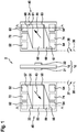
- Fig. 1 an exploded view of a fuel cell 2 according to the invention is shown.
- the fuel cell 2 has a membrane electrode unit 10, which comprises a first electrode 21, a second electrode 22 and a membrane 18.
- the two electrodes 21, 22 are arranged on opposite sides of the membrane 18 and are thus separated from one another by the membrane 18.
- the first electrode 21 is also referred to below as the anode 21 and the second electrode 22 is also referred to as the cathode 22 below.
- the electrodes 21, 22 are arranged congruently on the membrane 18.
- the anode 21 and the cathode 22 have a similar cross section and are attached to opposite regions of the membrane 18.
- the membrane electrode unit 10 is thus designed to be mirror-symmetrical.
- the centrally arranged membrane 18 protrudes beyond the electrodes 21, 22 applied on both sides.
- the membrane 18 is designed as a polymer electrolyte membrane.
- the membrane 18 is permeable to hydrogen ions, that is to say H + ions.
- the membrane 18 is also permeable to water vapor.
- water of reaction that arises at the cathode 22 during the reaction taking place in the fuel cell 2 can thus diffuse into the membrane 18 and through the membrane 18 to the anode 21.
- the fuel cell 2 also has two bipolar plates 40, which are connected to the membrane electrode unit 10 on both sides.
- the bipolar plates 40 are each shown here in a plan view.
- a first surface 33 of a bipolar plate 40 is shown here, which in the assembled state of the Fuel cell 2 facing the anode 21.
- a second surface 34 of the other bipolar plate 40 is shown, which surface faces the cathode 22 in the assembled state of the fuel cell 2.
- the one bipolar plate 40 When assembling the fuel cell 2, the one bipolar plate 40, the first surface 33 of which is shown, must therefore be rotated by 90 ° about a first axis 35 in a first direction of rotation 37.
- the other bipolar plate 40, the second surface 34 of which is shown, must be rotated through 90 ° in a second direction of rotation 38 about a second axis 36 when the fuel cell 2 is being assembled.
- the two bipolar plates 40 are pierced by a first supply channel 52 for supplying a fuel and by a second supply channel 64 for supplying an oxidizing agent. Furthermore, the two bipolar plates 40 are broken through by a first discharge channel 54 for discharging unused fuel and by a second discharge channel 62 for discharging unused oxidizing agent and water. The two bipolar plates 40 are also pierced by a third supply channel 74 for supplying a coolant and by a third discharge channel 72 for discharging the coolant. The coolant is used to cool the fuel cell 2 during operation.
- the first supply channel 52, the second discharge channel 62 and the third discharge channel 72 are introduced on a head side of the bipolar plates 40.
- the second supply channel 64, the first discharge channel 54 and the third supply channel 74 are introduced on an opposite foot side.
- the fuel thus flows from the head side to the foot side and the oxidizing agent and the coolant flow in the opposite direction from the foot side to the head side.
- the bipolar plates 40 each comprise a first distribution structure 50 for distributing the fuel, which is arranged on the first surface 33 and faces the anode 21.
- the first distribution structure 50 extends from a first edge 57 of the first supply channel 52 to a first edge 58 of the first discharge channel 54.
- the fuel flows from the fuel cell 2 during operation the first supply channel 52 to the first discharge channel 54 in a first flow direction 43.
- the first distribution structure 50 has a first inflow area 51, which adjoins the first edge 57 of the first feed channel 52, and a first outflow area 59, which adjoins the first edge 58 of the first discharge channel 54.
- a first main distribution area 53 which has a rectangular cross section, is arranged between the first inflow area 51 and the first outflow area 59.
- the bipolar plates 40 each include a second distribution structure 60 for distributing the oxidizing agent, which is arranged on the second surface 34 and faces the cathode 22.
- the second distribution structure 60 extends from a second edge 67 of the second supply channel 64 to a second edge 68 of the second discharge channel 62.
- the oxidizing agent flows from the second supply channel 64 to the second discharge channel 62 in a second flow direction 44.
- the second distribution structure 60 has a second inflow area 69, which adjoins the second edge 67 of the second feed channel 64, and a second outflow area 61, which adjoins the second edge 68 of the second discharge channel 62.
- a second main distribution area 63 which has a rectangular cross section, is arranged between the second inflow area 69 and the second outflow area 61.
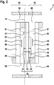
- FIG. 14 is a section through the assembled fuel cell 2 along the section lines A - A from FIG Figure 1 shown.
- the fuel cell 2 is part of a fuel cell stack which is composed of alternately arranged bipolar plates 40 and membrane electrode units 10.
- the bipolar plates 40 and the membrane electrode unit 10 are arranged in such a way that the anode 21 of the first distribution structure 50 faces the one bipolar plate 40 and that the cathode 22 of the second distribution structure 60 faces the other bipolar plate 40.
- the bipolar plates 40 comprise a third distribution structure 70, which extends from the third supply channel 74, not visible here, to the third discharge channel 72, also not visible here.
- the third distribution structure 70 is in each case arranged between the first distribution structure 50 and the second distribution structure 60 and serves to convey the coolant through the bipolar plate 40 and through the fuel cell 2.
- the anode 21 extends along the membrane 18 in a region which is spaced apart from the first edge 57 of the first feed channel 52, which is not visible here, and from the first edge 58 of the first discharge channel 54.
- the anode 21 extends along the membrane 18 in a region which is spaced apart from the first inflow region 51 and from the first outflow region 59.
- the anode 21 thus only adjoins the first main distribution area 53 of the first distribution structure 50 and protrudes into it.
- the membrane 18 thus has on the side of the anode 21 a region which is located adjacent to the first supply channel 52 and is free of the anode 21.
- the membrane 18 thus also has an area which is located adjacent to the first discharge channel 54 and is free of the anode 21. These two areas, which are free of the anode 21, directly adjoin the first distribution structure 50.
- the cathode 22 extends along the membrane 18 in a region which is spaced apart from the second edge 67 of the second supply channel 64, which is not visible here, and from the second edge 68 of the second discharge channel 62.
- the cathode 22 extends along the membrane 18 in a region which is spaced apart from the second inflow region 69 and from the second outflow region 61.
- the cathode 22 thus only adjoins the second main distribution area 63 of the second distribution structure 60 and protrudes into it.
- the membrane 18 thus has an area on the cathode 22 side which is located adjacent to the second supply channel 64 and is free of the cathode 22.
- the membrane 18 thus also has a region which is located adjacent to the second discharge channel 62 and is free of the cathode 22. These two areas, which are free of the cathode 22, directly adjoin the second distribution structure 60.
- fuel is conducted via the first supply channel 52 and the first distribution structure 50 to the anode 21 and further to the first discharge channel 54.
- the fuel also flows in the first flow direction 43 over the areas of the membrane 18 which are free of the anode 21.
- oxidizing agent is conducted via the second supply channel 64 and the second distribution structure 60 to the cathode 22 and further to the second discharge channel 62.
- the oxidizing agent thereby also flows in the second flow direction 44 over the regions of the membrane 18 which are free of the cathode 22.
- the fuel in this case hydrogen, is catalytically oxidized at the anode 21 with the release of electrons into protons.
- the protons pass through the membrane 18 to the cathode 22.
- the electrons released are diverted from the fuel cell 2 and flow to the cathode 22 via an external circuit. which have passed through the membrane 18 to the cathode 22, to water.
- the water that is produced at the cathode 22 during the reaction taking place in the fuel cell 2 can partially flow from the second distribution structure 60 in a first diffusion direction 47 into the membrane 18 and through the membrane 18 into the first distribution structure 50 and to the anode 21 diffuse.
- the water diffused in the first diffusion direction 47 is absorbed by the fuel flowing in the first distribution structure 50.
- the water absorbed by the fuel can then diffuse from the first distribution structure 50 in a second diffusion direction 48 into the membrane 18 and through the membrane 18 into the second distribution structure 60 and to the cathode 22. That diffused in the second diffusion direction 48 Water is taken up by the oxidizing agent flowing in the second distribution structure 60.
- the regions of the membrane 18 which are free of electrodes 21, 22 and adjoin the distribution structures 50, 60 thus enable constant diffusion of water into the membrane 18 and through the membrane 18.
- the membrane 18 is constantly moistened. Excess water is diverted from the fuel cell 2, in particular from the second distribution structure 60 via the second discharge channel 62.
- FIG. 11 shows a section through the assembled fuel cell 2 along the section line BB from FIG Figure 2 .
- the membrane 18 has a centrally located area on which the anode 21 is arranged.
- the membrane 18 also has a region which extends over part of the first main distribution region 53 and over the first inflow region 51 and which is free of the anode 21.
- the membrane 18 also has a region which extends over part of the first main distribution region 53 and over the first outflow region 59 and which is free from the anode 21.
Description
Die Erfindung betrifft eine Brennstoffzelle, welche mindestens eine Membran-Elektrodeneinheit mit einer ersten Elektrode und einer zweiten Elektrode, welche voneinander durch eine Membran getrennt sind, und mindestens zwei Bipolarplatten, die sich beidseitig an die Membran-Elektrodeneinheit anschließen, umfasst. Dabei sind die Bipolarplatten von einem ersten Zufuhrkanal zur Zufuhr eines Brennstoffs und von einem zweiten Zufuhrkanal zur Zufuhr eines Oxidationsmittels durchbrochen.The invention relates to a fuel cell which comprises at least one membrane-electrode unit with a first electrode and a second electrode, which are separated from one another by a membrane, and at least two bipolar plates, which adjoin the membrane-electrode unit on both sides. The bipolar plates are broken through by a first supply channel for supplying a fuel and by a second supply channel for supplying an oxidizing agent.
Eine Brennstoffzelle ist eine galvanische Zelle, welche die chemische Reaktionsenergie eines kontinuierlich zugeführten Brennstoffes und eines Oxidationsmittels in elektrische Energie wandelt. Eine Brennstoffzelle ist also ein elektrochemischer Energiewandler. Bei bekannten Brennstoffzellen werden insbesondere Wasserstoff (H2) und Sauerstoff (O2) in Wasser (H2O), elektrische Energie und Wärme gewandelt. Es sind aber auch Brennstoffzellen bekannt, welche mit Methanol oder Methan arbeiten.A fuel cell is a galvanic cell that converts the chemical reaction energy of a continuously supplied fuel and an oxidizing agent into electrical energy. A fuel cell is therefore an electrochemical energy converter. In known fuel cells, hydrogen (H2) and oxygen (O2) in particular are converted into water (H2O), electrical energy and heat. But there are also known fuel cells which work with methanol or methane.
Unter anderem sind Protonenaustauschmembran (Proton-Exchange-Membran = PEM) -Brennstoffzellen bekannt. Protonenaustauschmembran-Brennstoffzellen weisen eine zentral angeordnete Membran auf, die für Protonen, also für Wasserstoffionen, durchlässig ist. Das Oxidationsmittel, insbesondere Luftsauerstoff, ist dadurch räumlich von dem Brennstoff, insbesondere Wasserstoff, getrennt.Among other things, proton exchange membrane (PEM) fuel cells are known. Proton exchange membrane fuel cells have a centrally arranged membrane that is permeable to protons, i.e. hydrogen ions. The oxidizing agent, in particular atmospheric oxygen, is thereby spatially separated from the fuel, in particular hydrogen.
Protonenaustauschmembran-Brennstoffzellen weisen ferner eine Anode und eine Kathode auf. Der Brennstoff wird an der Anode der Brennstoffzelle zugeführt und katalytisch unter Abgabe von Elektronen zu Protonen oxidiert. Die Protonen gelangen durch die Membran zu der Kathode. Die abgegebenen Elektronen werden aus der Brennstoffzelle abgeleitet und fließen über einen externen Stromkreis zu der Kathode.Proton exchange membrane fuel cells also have an anode and a cathode. The fuel is fed to the anode of the fuel cell and is catalytically oxidized to protons, releasing electrons. The protons pass through the membrane to the cathode. The released electrons are derived from the fuel cell and flow to the cathode via an external circuit.
Das Oxidationsmittel wird an der Kathode der Brennstoffzelle zugeführt und es reagiert durch Aufnahme der Elektronen aus dem externen Stromkreis und Protonen, die durch die Membran zur Kathode gelangt sind, zu Wasser. Das so entstandene Wasser wird aus der Brennstoffzelle abgeleitet. Die Bruttoreaktion lautet:
O2 + 4H+ + 4e- → 2H2O
The oxidizing agent is fed to the fuel cell's cathode and it reacts to water by absorbing electrons from the external circuit and protons that have passed through the membrane to the cathode. The resulting water is drained from the fuel cell. The gross response is:
O 2 + 4H + + 4e - → 2H 2 O
Zwischen der Anode und der Kathode der Brennstoffzelle liegt dabei eine Spannung an. Zur Erhöhung der Spannung können mehrere Brennstoffzellen mechanisch hintereinander zu einem Brennstoffzellenstapel angeordnet und elektrisch in Reihe geschaltet werden.A voltage is applied between the anode and the cathode of the fuel cell. To increase the voltage, several fuel cells can be mechanically arranged one behind the other to form a fuel cell stack and electrically connected in series.
Zur gleichmäßigen Verteilung des Brennstoffs an der Anode sowie zur gleichmäßigen Verteilung des Oxidationsmittels an der Kathode sind Verteilerplatten vorgesehen, welche auch als Bipolarplatten bezeichnet werden. Die Bipolarplatten weisen beispielsweise kanalartige Strukturen zur Verteilung des Brennstoffs sowie des Oxidationsmittels auf. Die Bipolarplatten können ferner Strukturen zur Durchleitung einer Kühlflüssigkeit durch die Brennstoffzelle zur Abführung von Wärme aufweisen.Distributor plates, which are also referred to as bipolar plates, are provided for uniform distribution of the fuel on the anode and for uniform distribution of the oxidizing agent on the cathode. The bipolar plates have, for example, channel-like structures for distributing the fuel and the oxidizing agent. The bipolar plates can also have structures for conducting a cooling liquid through the fuel cell in order to dissipate heat.
Aus der
Die Membran der Membran-Elektrodeneinheit muss dabei feucht gehalten werden damit die Brennstoffzelle ordnungsgemäß funktioniert. Insbesondere bei Betrieb der Brennstoffzelle bei verhältnismäßig hoher Temperatur kann die Membran aufgrund der erhöhten Wasseraufnahmefähigkeit der Luft austrocknen, wodurch die Funktion der Brennstoffzelle beeinträchtigt werden kann.The membrane of the membrane electrode unit must be kept moist so that the fuel cell works properly. Particularly when the fuel cell is operated at a relatively high temperature, the membrane can dry out due to the increased water absorption capacity of the air, which can impair the function of the fuel cell.
Es wird eine Brennstoffzelle vorgeschlagen, welche mindestens eine Membran-Elektrodeneinheit mit einer ersten Elektrode und einer zweiten Elektrode, welche voneinander durch eine Membran getrennt sind, und mindestens zwei Bipolarplatten umfasst, die sich beidseitig an die Membran-Elektrodeneinheit anschließen. Dabei sind die Bipolarplatten von einem ersten Zufuhrkanal zur Zufuhr eines Brennstoffs und von einem zweiten Zufuhrkanal zur Zufuhr eines Oxidationsmittels durchbrochen. Eine erste Verteilstruktur zur Verteilung des Brennstoffs, die der ersten Elektrode zugewandt ist, schließt sich an eine erste Kante des ersten Zufuhrkanals an und eine zweite Verteilstruktur zur Verteilung des Oxidationsmittels, die der zweiten Elektrode zugewandt ist, schließt sich an eine zweite Kante des zweiten Zufuhrkanals an.A fuel cell is proposed which comprises at least one membrane electrode unit with a first electrode and a second electrode, which are separated from one another by a membrane, and at least two bipolar plates which are connected to the membrane electrode unit on both sides. The bipolar plates are broken through by a first supply channel for supplying a fuel and by a second supply channel for supplying an oxidizing agent. A first distribution structure for distributing the fuel, which faces the first electrode, adjoins a first edge of the first feed channel and a second distribution structure for distributing the oxidizing agent, which faces the second electrode, adjoins a second edge of the second feed channel at.
Die erste Elektrode wird auch als Anode bezeichnet und die zweite Elektrode wird auch als Kathode bezeichnet. Bei dem Brennstoff handelt es sich beispielsweise um Wasserstoff und das Oxidationsmittel ist beispielsweise Sauerstoff, insbesondere in der Umgebungsluft enthaltener Sauerstoff.The first electrode is also called the anode and the second electrode is also called the cathode. The fuel is, for example, hydrogen and the oxidizing agent is, for example, oxygen, in particular oxygen contained in the ambient air.
Erfindungsgemäß erstreckt die erste Elektrode sich an der Membran entlang in einem Bereich, welcher von der ersten Kante des ersten Zufuhrkanals beabstandet ist und die zweite Elektrode erstreckt sich an der Membran entlang in einem Bereich, welcher von der zweiten Kante des zweiten Zufuhrkanals beabstandet ist.According to the invention, the first electrode extends along the membrane in an area which is spaced apart from the first edge of the first supply channel and the second electrode extends along the membrane in an area which is spaced apart from the second edge of the second supply channel.
Die zentral angeordnete Membran überragt also die beidseitig aufgebrachten Elektroden. Die Membran weist somit beidseitig Bereiche auf, welche dem ersten Zufuhrkanal sowie dem zweiten Zufuhrkanal benachbart gelegen sind, die unmittelbar an die erste Verteilstruktur oder an die zweite Verteilstruktur angrenzen und dabei frei von den Elektroden sind.The centrally arranged membrane therefore protrudes beyond the electrodes applied on both sides. The membrane thus has on both sides areas which are located adjacent to the first supply channel and the second supply channel, which directly adjoin the first distribution structure or the second distribution structure and are free of the electrodes.
Brennstoff, der über den ersten Zufuhrkanal und die erste Verteilstruktur zu der ersten Elektrode geleitet wird, strömt somit auch über Bereiche der Membran und kann somit Feuchtigkeit in Form von Wasserdampf unmittelbar zu der Membran transportieren. Oxidationsmittel, das über den zweiten Zufuhrkanal und die zweite Verteilstruktur zu der zweiten Elektrode geleitet wird, strömt somit auch über Bereiche der Membran und kann somit Feuchtigkeit in Form von Wasserdampf unmittelbar zu der Membran transportieren.Fuel that is conducted to the first electrode via the first supply channel and the first distribution structure thus also flows over regions of the membrane and can thus transport moisture in the form of water vapor directly to the membrane. Oxidizing agent via the second supply channel and the second distribution structure is passed to the second electrode, thus also flows over areas of the membrane and can thus transport moisture in the form of water vapor directly to the membrane.
Bevorzugt ist die Membran auch für Wasserdampf durchlässig. Damit kann Feuchtigkeit in Form von Wasserdampf von der ersten Verteilstruktur durch die Membran hindurch zu der zweiten Verteilstruktur und auch von der zweiten Verteilstruktur durch die Membran hindurch zu der ersten Verteilstruktur transportiert werden.The membrane is preferably also permeable to water vapor. Moisture in the form of water vapor can thus be transported from the first distribution structure through the membrane to the second distribution structure and also from the second distribution structure through the membrane to the first distribution structure.
Gemäß einer vorteilhaften Ausgestaltung der Erfindung sind die Bipolarplatten von einem ersten Abfuhrkanal zur Abfuhr des Brennstoffs durchbrochen, wobei die erste Verteilstruktur sich an eine erste Kante des ersten Abfuhrkanals anschließt. Der erste Abfuhrkanal dient zur Abfuhr von nicht verbrauchtem Brennstoff aus der ersten Verteilstruktur. Dabei erstreckt die erste Elektrode sich an der Membran entlang in einem Bereich, welcher auch von der ersten Kante des ersten Abfuhrkanals beabstandet ist. Die Membran weist somit auch einen Bereich auf, welcher dem ersten Abfuhrkanal benachbart gelegen ist, der unmittelbar an die erste Verteilstruktur angrenzt und dabei frei von der ersten Elektrode ist.According to an advantageous embodiment of the invention, the bipolar plates are pierced by a first discharge channel for discharging the fuel, the first distribution structure being connected to a first edge of the first discharge channel. The first discharge channel serves to discharge unused fuel from the first distribution structure. The first electrode extends along the membrane in an area which is also spaced apart from the first edge of the first discharge channel. The membrane thus also has an area which is located adjacent to the first discharge channel, which directly adjoins the first distribution structure and is free of the first electrode.
Die erste Verteilstruktur weist vorzugsweise einen an die erste Kante des ersten Zufuhrkanals anschließenden ersten Einströmbereich und einen an die erste Kante des ersten Abfuhrkanals anschließenden ersten Ausströmbereich auf. Dabei ist zwischen dem ersten Einströmbereich und dem ersten Ausströmbereich ein erster Hauptverteilbereich angeordnet, welcher einen rechteckigen Querschnitt aufweist.The first distribution structure preferably has a first inflow area adjoining the first edge of the first supply channel and a first outflow area adjoining the first edge of the first discharge channel. A first main distribution area, which has a rectangular cross section, is arranged between the first inflow area and the first outflow area.
Bevorzugt erstreckt die erste Elektrode sich an der Membran entlang in einem Bereich, welcher von dem ersten Einströmbereich und von dem ersten Ausströmbereich beabstandet ist. Die erste Elektrode grenzt somit nur an den ersten Hauptverteilbereich der ersten Verteilstruktur an.The first electrode preferably extends along the membrane in an area which is spaced apart from the first inflow area and from the first outflow area. The first electrode therefore only adjoins the first main distribution area of the first distribution structure.
Gemäß einer vorteilhaften Ausgestaltung der Erfindung sind die Bipolarplatten von einem zweiten Abfuhrkanal zur Abfuhr des Oxidationsmittels durchbrochen, wobei die zweite Verteilstruktur sich an eine zweite Kante des zweiten Abfuhrkanals anschließt. Der zweite Abfuhrkanal dient zur Abfuhr von nicht verbrauchtem Oxidationsmittel aus der zweiten Verteilstruktur. Dabei erstreckt die zweite Elektrode sich an der Membran entlang in einem Bereich, welcher auch von der zweiten Kante des zweiten Abfuhrkanals beabstandet ist. Die Membran weist somit auch einen Bereich auf, welcher dem zweiten Abfuhrkanal benachbart gelegen ist, der unmittelbar an die zweite Verteilstruktur angrenzt und dabei frei von der zweiten Elektrode ist.According to an advantageous embodiment of the invention, the bipolar plates are pierced by a second discharge channel for discharging the oxidizing agent, wherein the second distribution structure adjoins a second edge of the second discharge channel. The second discharge channel serves to discharge unused oxidizing agent from the second distribution structure. The second electrode extends along the membrane in an area which is also spaced apart from the second edge of the second discharge channel. The membrane thus also has an area which is located adjacent to the second discharge channel, which directly adjoins the second distribution structure and is free of the second electrode.
Die zweite Verteilstruktur weist vorzugsweise einen an die zweite Kante des zweiten Zufuhrkanals anschließenden zweiten Einströmbereich und einen an die zweite Kante des zweiten Abfuhrkanals anschließenden zweiten Ausströmbereich auf. Dabei ist zwischen dem zweiten Einströmbereich und dem zweiten Ausströmbereich ein zweiter Hauptverteilbereich angeordnet, welcher einen rechteckigen Querschnitt aufweist.The second distribution structure preferably has a second inflow area adjoining the second edge of the second supply channel and a second outflow area adjoining the second edge of the second discharge channel. A second main distribution area, which has a rectangular cross section, is arranged between the second inflow area and the second outflow area.
Bevorzugt erstreckt die zweite Elektrode sich an der Membran entlang in einem Bereich, welcher von dem zweiten Einströmbereich und von dem zweiten Ausströmbereich beabstandet ist. Die zweite Elektrode grenzt somit nur an den zweiten Hauptverteilbereich der zweiten Verteilstruktur an.The second electrode preferably extends along the membrane in an area which is spaced apart from the second inflow area and from the second outflow area. The second electrode thus only adjoins the second main distribution area of the second distribution structure.
Vorzugsweise sind die Elektroden deckungsgleich an der Membran angeordnet. Die erste Elektrode und die zweite Elektrode weisen also einen gleichartigen Querschnitt auf und sind an gegenüberliegenden Bereichen der Membran angebracht. Die Membran-Elektrodeneinheit ist somit spiegelsymmetrisch ausgestaltet.The electrodes are preferably arranged congruently on the membrane. The first electrode and the second electrode therefore have a similar cross section and are attached to opposite regions of the membrane. The membrane electrode unit is thus designed to be mirror-symmetrical.
Eine erfindungsgemäße Brennstoffzelle findet vorteilhaft Verwendung in einem Elektrofahrzeug (EV).A fuel cell according to the invention is advantageously used in an electric vehicle (EV).
Durch die erfindungsgemäße Ausgestaltung der Brennstoffzelle werden Bereiche auf der Membran erzeugt, die unmittelbar an die Verteilstrukturen angrenzen und die frei von Elektroden sind. Dadurch kann die Membran der Membran-Elektrodeneinheit stets ausreichend befeuchtet werden. Auch bei Betrieb der Brennstoffzelle bei verhältnismäßig hoher Temperatur kann eine Austrocknung der Membran vermieden werden. Dabei kann ein externer Befeuchter zur Befeuchtung der Membran kleiner ausgelegt werden oder es ist keine Befeuchtung der Membran durch einen externen Befeuchter erforderlich, wodurch Platz und Kosten eingespart werden.The configuration of the fuel cell according to the invention creates areas on the membrane which directly adjoin the distribution structures and which are free of electrodes. This allows the membrane of the membrane electrode unit always be sufficiently moistened. Even when the fuel cell is operated at a relatively high temperature, the membrane can be prevented from drying out. An external humidifier for humidifying the membrane can be designed to be smaller, or the membrane does not need to be humidified by an external humidifier, which saves space and costs.
In die zweite Verteilstruktur einströmende Luft wird bereits vor Erreichen der Kathode erwärmt. Dadurch wird bereits vor der Kathode durch ein Dampfdruckgefälle Wasser von der ersten Verteilstruktur durch die Membran in die zweite Verteilstruktur übertragen. Dieser Vorgang findet in der ersten Verteilstruktur hinter der Anode statt. In der ersten Verteilstruktur bleibt daher mehr Weg sowie Zeit, um Wasser durch die Membran in die zweite Verteilstruktur abzugeben. Die hinter der Kathode mit Reaktionswasser angereicherte Luft hat zusätzlichen Weg sowie Zeit, um Wasser durch die Membran in die erste Verteilstruktur zu übertragen. In der ersten Verteilstruktur wird bereits vor der Anode, der einströmende Wasserstoff erwärmt und hat zusätzlichen Weg sowie Zeit, um Wasser von der zweiten Verteilstruktur aufzunehmen.Air flowing into the second distribution structure is heated before it reaches the cathode. As a result, water is transferred from the first distribution structure through the membrane into the second distribution structure through a vapor pressure gradient before the cathode. This process takes place in the first distribution structure behind the anode. In the first distribution structure, there is therefore more distance and time to deliver water through the membrane into the second distribution structure. The air enriched with reaction water behind the cathode has an additional path and time to transfer water through the membrane into the first distribution structure. In the first distribution structure, the inflowing hydrogen is heated before the anode and has an additional path and time to absorb water from the second distribution structure.
Ausführungsformen der Erfindung werden anhand der Zeichnungen und der nachfolgenden Beschreibung näher erläutert.Embodiments of the invention are explained in more detail with reference to the drawings and the following description.
Es zeigen:
- Figur 1
- eine Explosionsdarstellung einer Brennstoffzelle,
Figur 2- einen Schnitt durch die zusammengesetzte Brennstoffzelle entlang den Schnittlinien A - A aus
Figur 1 und - Figur 3
- einen Schnitt durch die zusammengesetzte Brennstoffzelle entlang der Schnittlinie B -
B aus Figur 2 .
- Figure 1
- an exploded view of a fuel cell,
- Figure 2
- a section through the assembled fuel cell along the section lines A - A
Figure 1 and - Figure 3
- a section through the assembled fuel cell along the section line B - B
Figure 2 .
In der nachfolgenden Beschreibung der Ausführungsformen der Erfindung werden gleiche oder ähnliche Elemente mit gleichen Bezugszeichen bezeichnet, wobei auf eine wiederholte Beschreibung dieser Elemente in Einzelfällen verzichtet wird. Die Figuren stellen den Gegenstand der Erfindung nur schematisch dar.In the following description of the embodiments of the invention, the same or similar elements are denoted by the same reference numerals, a repeated description of these elements being dispensed with in individual cases. The figures represent the subject matter of the invention only schematically.
In
Die Elektroden 21, 22 sind vorliegend deckungsgleich an der Membran 18 angeordnet. Die Anode 21 und die Kathode 22 weisen dabei einen gleichartigen Querschnitt auf und sind an gegenüberliegenden Bereichen der Membran 18 angebracht. Die Membran-Elektrodeneinheit 10 ist somit spiegelsymmetrisch ausgestaltet. Die zentral angeordnete Membran 18 überragt dabei die beidseitig aufgebrachten Elektroden 21, 22.In the present case, the
Die Membran 18 ist vorliegend als Polymerelektrolytmembran ausgebildet. Die Membran 18 ist für Wasserstoffionen, also H+-Ionen, durchlässig. Ebenso ist die Membran 18 auch für Wasserdampf durchlässig. Insbesondere Reaktionswasser, das bei der in der Brennstoffzelle 2 stattfindenden Reaktion an der Kathode 22 entsteht, kann somit in die Membran 18 und durch die Membran 18 hindurch zu der Anode 21 diffundieren.In the present case, the
Die Brennstoffzelle 2 weist ferner zwei Bipolarplatten 40 auf, die sich beidseitig an die Membran-Elektrodeneinheit 10 anschließen. Die Bipolarplatten 40 sind hier jeweils in einer Draufsicht dargestellt. Dabei ist von einer Bipolarplatte 40 eine erste Oberfläche 33 dargestellt, welche im zusammengebauten Zustand der Brennstoffzelle 2 der Anode 21 zugewandt ist. Von der anderen Bipolarplatte 40 ist eine zweite Oberfläche 34 dargestellt, welche im zusammengebauten Zustand der Brennstoffzelle 2 der Kathode 22 zugewandt ist.The
Beim Zusammenbau der Brennstoffzelle 2 muss die eine Bipolarplatte 40, deren erste Oberfläche 33 dargestellt ist, somit um eine erste Achse 35 in eine erste Drehrichtung 37 um 90° gedreht werden. Die andere Bipolarplatte 40, deren zweite Oberfläche 34 dargestellt ist, muss beim Zusammenbau der Brennstoffzelle 2 um eine zweite Achse 36 in eine zweite Drehrichtung 38 um 90° gedreht werden.When assembling the
Die beiden Bipolarplatten 40 sind von einem ersten Zufuhrkanal 52 zur Zufuhr eines Brennstoffs und von einem zweiten Zufuhrkanal 64 zur Zufuhr eines Oxidationsmittels durchbrochen. Ferner sind die beiden Bipolarplatten 40 von einem ersten Abfuhrkanal 54 zur Abfuhr von nicht verbrauchtem Brennstoff und von einem zweiten Abfuhrkanal 62 zur Abfuhr von nicht verbrauchtem Oxidationsmittel sowie von Wasser durchbrochen. Die beiden Bipolarplatten 40 sind auch von einem dritten Zufuhrkanal 74 zur Zufuhr eines Kühlmittels und von einem dritten Abfuhrkanal 72 zur Abfuhr des Kühlmittels durchbrochen sind. Das Kühlmittel dient zum Kühlen der Brennstoffzelle 2 im Betrieb.The two
Der erste Zufuhrkanal 52, der zweite Abfuhrkanal 62 und der dritten Abfuhrkanal 72 sind dabei an einer Kopfseite der Bipolarplatten 40 eingebracht. Der zweite Zufuhrkanal 64, der erste Abfuhrkanal 54 und der dritte Zufuhrkanal 74 sind an einer gegenüberliegenden Fußseite eingebracht. Im Betrieb der Brennstoffzelle 2 fließt der Brennstoff somit von der Kopfseite zu der Fußseite und das Oxidationsmittel sowie das Kühlmittel fließen in die entgegengesetzte Richtung von der Fußseite zu der Kopfseite.The
Die Bipolarplatten 40 umfassen jeweils eine erste Verteilstruktur 50 zur Verteilung des Brennstoffs, die auf der ersten Oberfläche 33 angeordnet und der Anode 21 zugewandt ist. Die erste Verteilstruktur 50 erstreckt sich von einer ersten Kante 57 des ersten Zufuhrkanals 52 bis zu einer ersten Kante 58 des ersten Abfuhrkanals 54. Der Brennstoff fließt in Betrieb der Brennstoffzelle 2 von dem ersten Zufuhrkanal 52 zu dem ersten Abfuhrkanal 54 in eine erste Strömungsrichtung 43.The
Die erste Verteilstruktur 50 weist einen ersten Einströmbereich 51, welcher an die erste Kante 57 des ersten Zufuhrkanals 52 anschließt, und einen ersten Ausströmbereich 59, welcher an die erste Kante 58 des ersten Abfuhrkanals 54 anschließt, auf. Zwischen dem ersten Einströmbereich 51 und dem ersten Ausströmbereich 59 ein erster Hauptverteilbereich 53 angeordnet, welcher einen rechteckigen Querschnitt aufweist.The
Die Bipolarplatten 40 umfassen jeweils eine zweite Verteilstruktur 60 zur Verteilung des Oxidationsmittels, die auf der zweiten Oberfläche 34 angeordnet und der Kathode 22 zugewandt ist. Die zweite Verteilstruktur 60 erstreckt sich von einer zweiten Kante 67 des zweiten Zufuhrkanals 64 bis zu einer zweiten Kante 68 des zweiten Abfuhrkanals 62. Das Oxidationsmittel fließt in Betrieb der Brennstoffzelle 2 von dem zweiten Zufuhrkanal 64 zu dem zweiten Abfuhrkanal 62 in eine zweite Strömungsrichtung 44.The
Die zweite Verteilstruktur 60 weist einen zweiten Einströmbereich 69, welcher an die zweite Kante 67 des zweiten Zufuhrkanals 64 anschließt, und einen zweiten Ausströmbereich 61, welcher an die zweite Kante 68 des zweiten Abfuhrkanals 62 anschließt, auf. Zwischen dem zweiten Einströmbereich 69 und dem zweiten Ausströmbereich 61 ein zweiter Hauptverteilbereich 63 angeordnet, welcher einen rechteckigen Querschnitt aufweist.The
In
Die Bipolarplatten 40 umfassen eine dritte Verteilstruktur 70, welche sich von dem hier nicht sichtbaren dritten Zufuhrkanal 74 zu dem hier ebenfalls nicht sichtbaren dritten Abfuhrkanal 72 erstreckt. Die dritte Verteilstruktur 70 ist dabei jeweils zwischen der ersten Verteilstruktur 50 und der zweiten Verteilstruktur 60 angeordnet und dient zur Durchleitung des Kühlmittels durch die Bipolarplatte 40 und durch die Brennstoffzelle 2.The
Die Anode 21 erstreckt sich an der Membran 18 entlang in einem Bereich, welcher von der hier nicht sichtbaren ersten Kante 57 des ersten Zufuhrkanals 52 und von der ersten Kante 58 des ersten Abfuhrkanals 54 beabstandet ist. Insbesondere erstreckt die Anode 21 an der Membran 18 entlang in einem Bereich, welcher von dem ersten Einströmbereich 51 und von dem ersten Ausströmbereich 59 beabstandet ist. Die Anode 21 grenzt somit nur an den ersten Hauptverteilbereich 53 der ersten Verteilstruktur 50 an und ragt in diesen hinein.The
Die Membran 18 weist somit auf der Seite der Anode 21 einen Bereich auf, welcher dem ersten Zufuhrkanal 52 benachbart gelegen ist und dabei frei von der Anode 21 ist. Die Membran 18 weist somit auch einen Bereich auf, welcher dem ersten Abfuhrkanal 54 benachbart gelegen ist und dabei frei von der Anode 21 ist. Diese beiden Bereiche, die frei von der Anode 21 sind, grenzen unmittelbar an die erste Verteilstruktur 50 an.The
Die Kathode 22 erstreckt sich an der Membran 18 entlang in einem Bereich, welcher und von der hier nicht sichtbaren zweiten Kante 67 des zweiten Zufuhrkanals 64 und von der zweiten Kante 68 des zweiten Abfuhrkanals 62 beabstandet ist. Insbesondere erstreckt sich die Kathode 22 an der Membran 18 entlang in einem Bereich, welcher von dem zweiten Einströmbereich 69 und von dem zweiten Ausströmbereich 61 beabstandet ist. Die Kathode 22 grenzt somit nur an den zweiten Hauptverteilbereich 63 der zweiten Verteilstruktur 60 an und ragt in diesen hinein.The
Die Membran 18 weist somit auf der Seite der Kathode 22 einen Bereich auf, welcher dem zweiten Zufuhrkanal 64 benachbart gelegen ist und dabei frei von der Kathode 22 ist. Die Membran 18 weist somit auch einen Bereich auf, welcher dem zweiten Abfuhrkanal 62 benachbart gelegen ist und dabei frei von der Kathode 22 ist. Diese beiden Bereiche, die frei von der Kathode 22 sind, grenzen unmittelbar an die zweite Verteilstruktur 60 an.The
Im Betrieb der Brennstoffzelle 2 wird Brennstoff über den ersten Zufuhrkanal 52 und die erste Verteilstruktur 50 zu der Anode 21 und weiter zu dem ersten Abfuhrkanal 54 geleitet. Dabei strömt der Brennstoff in der ersten Strömungsrichtung 43 auch über die Bereiche der Membran 18, welche frei von der Anode 21 sind.When the
Im Betrieb der Brennstoffzelle 2 wird Oxidationsmittel über den zweiten Zufuhrkanal 64 und die zweite Verteilstruktur 60 zu der Kathode 22 und weiter zu dem zweiten Abfuhrkanal 62 geleitet. Dabei strömt das Oxidationsmittel in der zweiten Strömungsrichtung 44 auch über die Bereiche der Membran 18, welche frei von der Kathode 22 sind.When the
Der Brennstoff, vorliegend Wasserstoff, wird an der Anode 21 katalytisch unter Abgabe von Elektronen zu Protonen oxidiert. Die Protonen gelangen durch die Membran 18 zu der Kathode 22. Die abgegebenen Elektronen werden aus der Brennstoffzelle 2 abgeleitet und fließen über einen externen Stromkreis zu der Kathode 22. Das Oxidationsmittel, vorliegend Luftsauerstoff, reagiert durch Aufnahme der Elektronen aus dem externen Stromkreis und Protonen, die durch die Membran 18 zu der Kathode 22 gelangt sind, zu Wasser.The fuel, in this case hydrogen, is catalytically oxidized at the
Das Wasser, das bei der in der Brennstoffzelle 2 stattfindenden Reaktion an der Kathode 22 entsteht, kann teilweise von der zweiten Verteilstruktur 60 in eine erste Diffusionsrichtung 47 in die Membran 18 und durch die Membran 18 hindurch in die erste Verteilstruktur 50 und zu der Anode 21 diffundieren. Das in die erste Diffusionsrichtung 47 diffundierte Wasser wird dabei von dem in der ersten Verteilstruktur 50 fließenden Brennstoff aufgenommen.The water that is produced at the
Das von dem Brennstoff aufgenommene Wasser kann anschließend von der ersten Verteilstruktur 50 in eine zweite Diffusionsrichtung 48 in die Membran 18 und durch die Membran 18 hindurch in die zweite Verteilstruktur 60 und zu der Kathode 22 diffundieren. Das in die zweite Diffusionsrichtung 48 diffundierte Wasser wird dabei von dem in der zweiten Verteilstruktur 60 fließenden Oxidationsmittel aufgenommen.The water absorbed by the fuel can then diffuse from the
Die Bereiche der Membran 18, welche frei von Elektroden 21, 22 sind und an die Verteilstrukturen 50, 60 angrenzen, ermöglichen somit eine ständige Diffusion von Wasser in die Membran 18 hinein und durch die Membran 18 hindurch. Dadurch wird die Membran 18 ständig befeuchtet. Überschüssiges Wasser wird, insbesondere aus der zweiten Verteilstruktur 60 über den zweiten Abfuhrkanal 62, aus der Brennstoffzelle 2 abgeleitet.The regions of the
Die Erfindung ist nicht auf die hier beschriebenen Ausführungsbeispiele und die darin hervorgehobenen Aspekte beschränkt. Vielmehr ist innerhalb des durch die Ansprüche angegebenen Bereichs eine Vielzahl von Abwandlungen möglich, die im Rahmen fachmännischen Handelns liegen.The invention is not restricted to the exemplary embodiments described here and the aspects emphasized therein. Rather, within the range specified by the claims, a large number of modifications are possible that are within the scope of expert knowledge.
Claims (10)
- Fuel cell (2) comprising
at least one membrane electrode unit (10) having a first electrode (21) and a second electrode (22), separated from one another by a membrane (18), and
at least two bipolar plates (40) that adjoin the membrane electrode unit (10) on either side, wherein the bipolar plates (40) are interrupted by a first feed conduit (52) for supply of a fuel and by a second feed conduit (64) for supply of an oxidant, wherein a first distribution structure (50) facing the first electrode (21) adjoins a first edge (57) of the first feed conduit (52), and
a second distribution structure (60) facing the second electrode (22) adjoins a second edge (67) of the second feed conduit (64), wherein
the first electrode (21) extends along the membrane (18) in a region spaced apart from the first edge (57) of the first feed conduit (52), and in that
the second electrode (22) extends along the membrane (18) in a region spaced apart from the second edge (67) of the second feed conduit (64),
characterized in that
the membrane (18) has regions on both sides which are adjacent to the first feed channel (52) and the second feed channel (64) and which directly adjoin the first distribution structure (50) or the second distribution structure (60) and are free of the electrodes (21, 22). - Fuel cell (2) according to Claim 1, characterized in that the membrane (18) is permeable to water vapour.
- Fuel cell (2) according to either of the preceding claims, characterized in that
the bipolar plates (40) are interrupted by a first drain conduit (54) for draining of the fuel, wherein the first distribution structure (50) adjoins a first edge (58) of the first drain conduit (54), and
the first electrode (21) extends along the membrane (18) in a region spaced apart from the first edge (58) of the first drain conduit (54). - Fuel cell (2) according to Claim 3, characterized in that
the first distribution structure (50) has
a first inflow region (51) that adjoins the first edge (57) of the first feed conduit (52) and
a first outflow region (59) that adjoins the first edge (58) of the first drain conduit (54), wherein
a first main distribution region (53) having a rectangular cross section is disposed between the first inflow region (51) and the first outflow region (59) . - Fuel cell (2) according to Claim 4, characterized in that
the first electrode (21) extends along the membrane (18) in a region spaced apart from the first inflow region (51) and from the first outflow region (59). - Fuel cell (2) according to any of the preceding claims, characterized in that
the bipolar plates (40) are interrupted by a second drain conduit (62) for draining of the oxidant, where the second distribution structure (60) adjoins a second edge (68) of the second drain conduit (62), and
the second electrode (22) extends along the membrane (18) in a region spaced apart from the second edge (68) of the second drain conduit (62). - Fuel cell (2) according to Claim 6, characterized in that
the second distribution structure (60) has
a second inflow region (69) that adjoins the second edge (67) of the second feed conduit (64) and
a second outflow region (61) that adjoins the second edge (68) of the second drain conduit (62), where
a second main distribution region (63) having a rectangular cross section is disposed between the second inflow region (69) and the second outflow region (61). - Fuel cell (2) according to Claim 7, characterized in that
the second electrode (22) extends along the membrane (18) in a region spaced apart from the second inflow region (69) and from the second outflow region (61). - Fuel cell (2) according to any of the preceding claims, characterized in that
the electrodes (21, 22) are in a congruent arrangement with the membrane (18). - Use of a fuel cell (2) according to any of the preceding claims in an electrical vehicle (EV).
Applications Claiming Priority (2)
| Application Number | Priority Date | Filing Date | Title |
|---|---|---|---|
| DE102016224676.3A DE102016224676A1 (en) | 2016-12-12 | 2016-12-12 | fuel cell |
| PCT/EP2017/080965 WO2018108547A1 (en) | 2016-12-12 | 2017-11-30 | Fuel cell |
Publications (2)
| Publication Number | Publication Date |
|---|---|
| EP3552262A1 EP3552262A1 (en) | 2019-10-16 |
| EP3552262B1 true EP3552262B1 (en) | 2021-01-06 |
Family
ID=60484394
Family Applications (1)
| Application Number | Title | Priority Date | Filing Date |
|---|---|---|---|
| EP17805216.3A Active EP3552262B1 (en) | 2016-12-12 | 2017-11-30 | Fuel cell |
Country Status (7)
| Country | Link |
|---|---|
| US (1) | US11081707B2 (en) |
| EP (1) | EP3552262B1 (en) |
| JP (1) | JP7171571B2 (en) |
| KR (1) | KR102469253B1 (en) |
| CN (1) | CN110268565B (en) |
| DE (1) | DE102016224676A1 (en) |
| WO (1) | WO2018108547A1 (en) |
Families Citing this family (1)
| Publication number | Priority date | Publication date | Assignee | Title |
|---|---|---|---|---|
| CN117334946B (en) * | 2023-12-01 | 2024-03-29 | 北京氢璞创能科技有限公司 | Proton exchange membrane fuel cell unit cell with optimized flow field |
Family Cites Families (7)
| Publication number | Priority date | Publication date | Assignee | Title |
|---|---|---|---|---|
| JP2000323159A (en) * | 1999-05-11 | 2000-11-24 | Fuji Electric Co Ltd | Solid polymer type fuel cell |
| JP4981400B2 (en) | 2006-05-01 | 2012-07-18 | 本田技研工業株式会社 | Fuel cell |
| US8475972B2 (en) * | 2006-05-01 | 2013-07-02 | Honda Motor Co., Ltd. | Fuel cell |
| JP5217284B2 (en) * | 2007-08-01 | 2013-06-19 | 日産自動車株式会社 | Fuel cell |
| CN104170147B (en) * | 2012-03-23 | 2016-10-12 | 本田技研工业株式会社 | Fuel cell |
| DE102013226815A1 (en) | 2013-12-20 | 2015-06-25 | Robert Bosch Gmbh | fuel cell |
| FR3026232B1 (en) | 2014-09-19 | 2021-04-02 | Commissariat Energie Atomique | FLUID FLUID GUIDE PLATE FOR ELECTROCHEMICAL REACTOR AND ASSEMBLY CONTAINING THIS PLATE |
-
2016
- 2016-12-12 DE DE102016224676.3A patent/DE102016224676A1/en not_active Withdrawn
-
2017
- 2017-11-30 CN CN201780086235.9A patent/CN110268565B/en active Active
- 2017-11-30 JP JP2019530748A patent/JP7171571B2/en active Active
- 2017-11-30 US US16/468,382 patent/US11081707B2/en active Active
- 2017-11-30 WO PCT/EP2017/080965 patent/WO2018108547A1/en active Application Filing
- 2017-11-30 EP EP17805216.3A patent/EP3552262B1/en active Active
- 2017-11-30 KR KR1020197019983A patent/KR102469253B1/en active IP Right Grant
Non-Patent Citations (1)
| Title |
|---|
| None * |
Also Published As
| Publication number | Publication date |
|---|---|
| DE102016224676A1 (en) | 2018-06-14 |
| JP7171571B2 (en) | 2022-11-15 |
| KR102469253B1 (en) | 2022-11-21 |
| US20190334181A1 (en) | 2019-10-31 |
| US11081707B2 (en) | 2021-08-03 |
| WO2018108547A1 (en) | 2018-06-21 |
| CN110268565B (en) | 2022-08-12 |
| KR20190090007A (en) | 2019-07-31 |
| JP2020513665A (en) | 2020-05-14 |
| CN110268565A (en) | 2019-09-20 |
| EP3552262A1 (en) | 2019-10-16 |
Similar Documents
| Publication | Publication Date | Title |
|---|---|---|
| EP3884535B1 (en) | Fuel cell plate, bipolar plate and fuel cell device | |
| DE102019204240A1 (en) | Bipolar plate for a fuel cell stack and a fuel cell stack | |
| DE10220183A1 (en) | Polymer electrolyte fuel cell has stacked unit cells comprising water electrolysis and fuel cell portions within single plane of unit cell and water passage in interconnector to feed water to water electrolysis portion | |
| EP3552262B1 (en) | Fuel cell | |
| DE102019218380A1 (en) | Fuel cell assembly and method for manufacturing a fuel cell assembly | |
| DE10233982B4 (en) | Bipolar plate for a fuel cell and fuel cell stack | |
| WO2022111922A1 (en) | Bipolar plate for an electrochemical cell, arrangement of electrochemical cells, and method for operating said arrangement of electrochemical cells | |
| EP1833112B1 (en) | Electrode membrane unit and fuel cell | |
| WO2003090301A2 (en) | Electrode plate comprising a humidification region | |
| WO2022111924A1 (en) | Bipolar plate for an electrochemical cell, arrangement of electrochemical cells, and method for operating an arrangement of electrochemical cells | |
| DE102009043208A1 (en) | Material design to allow fuel cell performance at high center temperature with ultrathin electrodes | |
| DE102019206117A1 (en) | Fuel cell stacks comprising variable biopolar plates | |
| DE102019205069A1 (en) | Bipolar plate for fuel cells, fuel cell stacks with such bipolar plates and vehicles with such a fuel cell stack | |
| DE102014219164A1 (en) | Fuel cell stack with integrated humidifier and vehicle with such | |
| WO2020152084A1 (en) | Bipolar plate for a fuel cell, and fuel cell | |
| DE102018201056A1 (en) | Fuel cell and fuel cell stack | |
| DE102020128436A1 (en) | Fabric structure with integrated humidification and dehumidification function for a bipolar plate and for a fuel cell stack | |
| DE102022205235A1 (en) | Method for operating at least one electrochemical cell | |
| DE102022200797A1 (en) | Membrane-electrode assembly, arrangement of electrochemical cells and method for producing a membrane-electrode assembly | |
| DE102020128562A1 (en) | Bipolar plate with insertable screen and fuel cell stack | |
| DE102019220604A1 (en) | Bipolar plate for a fuel cell and method for media distribution in a bipolar plate | |
| DE102020215014A1 (en) | Bipolar plate for an electrochemical cell and electrochemical cell | |
| WO2022090125A1 (en) | Flow field plate and fuel cell stack | |
| DE102020101528A1 (en) | Fuel cell device and motor vehicle with a fuel cell device | |
| DE102020203683A1 (en) | Device for media feed-through and method of production |
Legal Events
| Date | Code | Title | Description |
|---|---|---|---|
| STAA | Information on the status of an ep patent application or granted ep patent |
Free format text: STATUS: UNKNOWN |
|
| STAA | Information on the status of an ep patent application or granted ep patent |
Free format text: STATUS: THE INTERNATIONAL PUBLICATION HAS BEEN MADE |
|
| PUAI | Public reference made under article 153(3) epc to a published international application that has entered the european phase |
Free format text: ORIGINAL CODE: 0009012 |
|
| STAA | Information on the status of an ep patent application or granted ep patent |
Free format text: STATUS: REQUEST FOR EXAMINATION WAS MADE |
|
| 17P | Request for examination filed |
Effective date: 20190712 |
|
| AK | Designated contracting states |
Kind code of ref document: A1 Designated state(s): AL AT BE BG CH CY CZ DE DK EE ES FI FR GB GR HR HU IE IS IT LI LT LU LV MC MK MT NL NO PL PT RO RS SE SI SK SM TR |
|
| AX | Request for extension of the european patent |
Extension state: BA ME |
|
| DAV | Request for validation of the european patent (deleted) | ||
| DAX | Request for extension of the european patent (deleted) | ||
| RAP1 | Party data changed (applicant data changed or rights of an application transferred) |
Owner name: ROBERT BOSCH GMBH |
|
| REG | Reference to a national code |
Ref country code: DE Ref legal event code: R079 Ref document number: 502017009007 Country of ref document: DE Free format text: PREVIOUS MAIN CLASS: H01M0008025800 Ipc: H01M0008041190 |
|
| GRAP | Despatch of communication of intention to grant a patent |
Free format text: ORIGINAL CODE: EPIDOSNIGR1 |
|
| STAA | Information on the status of an ep patent application or granted ep patent |
Free format text: STATUS: GRANT OF PATENT IS INTENDED |
|
| RIC1 | Information provided on ipc code assigned before grant |
Ipc: H01M 8/0258 20160101ALI20200528BHEP Ipc: H01M 8/04119 20160101AFI20200528BHEP Ipc: H01M 8/1018 20160101ALN20200528BHEP Ipc: H01M 8/2483 20160101ALI20200528BHEP |
|
| INTG | Intention to grant announced |
Effective date: 20200619 |
|
| GRAS | Grant fee paid |
Free format text: ORIGINAL CODE: EPIDOSNIGR3 |
|
| GRAA | (expected) grant |
Free format text: ORIGINAL CODE: 0009210 |
|
| STAA | Information on the status of an ep patent application or granted ep patent |
Free format text: STATUS: THE PATENT HAS BEEN GRANTED |
|
| AK | Designated contracting states |
Kind code of ref document: B1 Designated state(s): AL AT BE BG CH CY CZ DE DK EE ES FI FR GB GR HR HU IE IS IT LI LT LU LV MC MK MT NL NO PL PT RO RS SE SI SK SM TR |
|
| REG | Reference to a national code |
Ref country code: GB Ref legal event code: FG4D Free format text: NOT ENGLISH |
|
| REG | Reference to a national code |
Ref country code: AT Ref legal event code: REF Ref document number: 1353345 Country of ref document: AT Kind code of ref document: T Effective date: 20210115 Ref country code: CH Ref legal event code: EP |
|
| REG | Reference to a national code |
Ref country code: DE Ref legal event code: R096 Ref document number: 502017009007 Country of ref document: DE |
|
| REG | Reference to a national code |
Ref country code: IE Ref legal event code: FG4D Free format text: LANGUAGE OF EP DOCUMENT: GERMAN |
|
| REG | Reference to a national code |
Ref country code: NL Ref legal event code: MP Effective date: 20210106 |
|
| REG | Reference to a national code |
Ref country code: LT Ref legal event code: MG9D |
|
| PG25 | Lapsed in a contracting state [announced via postgrant information from national office to epo] |
Ref country code: NO Free format text: LAPSE BECAUSE OF FAILURE TO SUBMIT A TRANSLATION OF THE DESCRIPTION OR TO PAY THE FEE WITHIN THE PRESCRIBED TIME-LIMIT Effective date: 20210406 Ref country code: PT Free format text: LAPSE BECAUSE OF FAILURE TO SUBMIT A TRANSLATION OF THE DESCRIPTION OR TO PAY THE FEE WITHIN THE PRESCRIBED TIME-LIMIT Effective date: 20210506 Ref country code: FI Free format text: LAPSE BECAUSE OF FAILURE TO SUBMIT A TRANSLATION OF THE DESCRIPTION OR TO PAY THE FEE WITHIN THE PRESCRIBED TIME-LIMIT Effective date: 20210106 Ref country code: HR Free format text: LAPSE BECAUSE OF FAILURE TO SUBMIT A TRANSLATION OF THE DESCRIPTION OR TO PAY THE FEE WITHIN THE PRESCRIBED TIME-LIMIT Effective date: 20210106 Ref country code: GR Free format text: LAPSE BECAUSE OF FAILURE TO SUBMIT A TRANSLATION OF THE DESCRIPTION OR TO PAY THE FEE WITHIN THE PRESCRIBED TIME-LIMIT Effective date: 20210407 Ref country code: BG Free format text: LAPSE BECAUSE OF FAILURE TO SUBMIT A TRANSLATION OF THE DESCRIPTION OR TO PAY THE FEE WITHIN THE PRESCRIBED TIME-LIMIT Effective date: 20210406 Ref country code: LT Free format text: LAPSE BECAUSE OF FAILURE TO SUBMIT A TRANSLATION OF THE DESCRIPTION OR TO PAY THE FEE WITHIN THE PRESCRIBED TIME-LIMIT Effective date: 20210106 |
|
| PG25 | Lapsed in a contracting state [announced via postgrant information from national office to epo] |
Ref country code: SE Free format text: LAPSE BECAUSE OF FAILURE TO SUBMIT A TRANSLATION OF THE DESCRIPTION OR TO PAY THE FEE WITHIN THE PRESCRIBED TIME-LIMIT Effective date: 20210106 Ref country code: RS Free format text: LAPSE BECAUSE OF FAILURE TO SUBMIT A TRANSLATION OF THE DESCRIPTION OR TO PAY THE FEE WITHIN THE PRESCRIBED TIME-LIMIT Effective date: 20210106 Ref country code: PL Free format text: LAPSE BECAUSE OF FAILURE TO SUBMIT A TRANSLATION OF THE DESCRIPTION OR TO PAY THE FEE WITHIN THE PRESCRIBED TIME-LIMIT Effective date: 20210106 Ref country code: LV Free format text: LAPSE BECAUSE OF FAILURE TO SUBMIT A TRANSLATION OF THE DESCRIPTION OR TO PAY THE FEE WITHIN THE PRESCRIBED TIME-LIMIT Effective date: 20210106 |
|
| PG25 | Lapsed in a contracting state [announced via postgrant information from national office to epo] |
Ref country code: IS Free format text: LAPSE BECAUSE OF FAILURE TO SUBMIT A TRANSLATION OF THE DESCRIPTION OR TO PAY THE FEE WITHIN THE PRESCRIBED TIME-LIMIT Effective date: 20210506 |
|
| REG | Reference to a national code |
Ref country code: DE Ref legal event code: R097 Ref document number: 502017009007 Country of ref document: DE |
|
| PG25 | Lapsed in a contracting state [announced via postgrant information from national office to epo] |
Ref country code: SM Free format text: LAPSE BECAUSE OF FAILURE TO SUBMIT A TRANSLATION OF THE DESCRIPTION OR TO PAY THE FEE WITHIN THE PRESCRIBED TIME-LIMIT Effective date: 20210106 Ref country code: CZ Free format text: LAPSE BECAUSE OF FAILURE TO SUBMIT A TRANSLATION OF THE DESCRIPTION OR TO PAY THE FEE WITHIN THE PRESCRIBED TIME-LIMIT Effective date: 20210106 Ref country code: EE Free format text: LAPSE BECAUSE OF FAILURE TO SUBMIT A TRANSLATION OF THE DESCRIPTION OR TO PAY THE FEE WITHIN THE PRESCRIBED TIME-LIMIT Effective date: 20210106 |
|
| PLBE | No opposition filed within time limit |
Free format text: ORIGINAL CODE: 0009261 |
|
| STAA | Information on the status of an ep patent application or granted ep patent |
Free format text: STATUS: NO OPPOSITION FILED WITHIN TIME LIMIT |
|
| PG25 | Lapsed in a contracting state [announced via postgrant information from national office to epo] |
Ref country code: DK Free format text: LAPSE BECAUSE OF FAILURE TO SUBMIT A TRANSLATION OF THE DESCRIPTION OR TO PAY THE FEE WITHIN THE PRESCRIBED TIME-LIMIT Effective date: 20210106 Ref country code: SK Free format text: LAPSE BECAUSE OF FAILURE TO SUBMIT A TRANSLATION OF THE DESCRIPTION OR TO PAY THE FEE WITHIN THE PRESCRIBED TIME-LIMIT Effective date: 20210106 Ref country code: RO Free format text: LAPSE BECAUSE OF FAILURE TO SUBMIT A TRANSLATION OF THE DESCRIPTION OR TO PAY THE FEE WITHIN THE PRESCRIBED TIME-LIMIT Effective date: 20210106 |
|
| 26N | No opposition filed |
Effective date: 20211007 |
|
| PG25 | Lapsed in a contracting state [announced via postgrant information from national office to epo] |
Ref country code: ES Free format text: LAPSE BECAUSE OF FAILURE TO SUBMIT A TRANSLATION OF THE DESCRIPTION OR TO PAY THE FEE WITHIN THE PRESCRIBED TIME-LIMIT Effective date: 20210106 Ref country code: AL Free format text: LAPSE BECAUSE OF FAILURE TO SUBMIT A TRANSLATION OF THE DESCRIPTION OR TO PAY THE FEE WITHIN THE PRESCRIBED TIME-LIMIT Effective date: 20210106 |
|
| PG25 | Lapsed in a contracting state [announced via postgrant information from national office to epo] |
Ref country code: SI Free format text: LAPSE BECAUSE OF FAILURE TO SUBMIT A TRANSLATION OF THE DESCRIPTION OR TO PAY THE FEE WITHIN THE PRESCRIBED TIME-LIMIT Effective date: 20210106 |
|
| PG25 | Lapsed in a contracting state [announced via postgrant information from national office to epo] |
Ref country code: IS Free format text: LAPSE BECAUSE OF FAILURE TO SUBMIT A TRANSLATION OF THE DESCRIPTION OR TO PAY THE FEE WITHIN THE PRESCRIBED TIME-LIMIT Effective date: 20210506 |
|
| PG25 | Lapsed in a contracting state [announced via postgrant information from national office to epo] |
Ref country code: MC Free format text: LAPSE BECAUSE OF FAILURE TO SUBMIT A TRANSLATION OF THE DESCRIPTION OR TO PAY THE FEE WITHIN THE PRESCRIBED TIME-LIMIT Effective date: 20210106 |
|
| REG | Reference to a national code |
Ref country code: CH Ref legal event code: PL |
|
| PG25 | Lapsed in a contracting state [announced via postgrant information from national office to epo] |
Ref country code: LU Free format text: LAPSE BECAUSE OF NON-PAYMENT OF DUE FEES Effective date: 20211130 Ref country code: BE Free format text: LAPSE BECAUSE OF NON-PAYMENT OF DUE FEES Effective date: 20211130 |
|
| REG | Reference to a national code |
Ref country code: BE Ref legal event code: MM Effective date: 20211130 |
|
| PG25 | Lapsed in a contracting state [announced via postgrant information from national office to epo] |
Ref country code: LI Free format text: LAPSE BECAUSE OF NON-PAYMENT OF DUE FEES Effective date: 20211130 Ref country code: CH Free format text: LAPSE BECAUSE OF NON-PAYMENT OF DUE FEES Effective date: 20211130 |
|
| PG25 | Lapsed in a contracting state [announced via postgrant information from national office to epo] |
Ref country code: IE Free format text: LAPSE BECAUSE OF NON-PAYMENT OF DUE FEES Effective date: 20211130 |
|
| PGFP | Annual fee paid to national office [announced via postgrant information from national office to epo] |
Ref country code: DE Payment date: 20230124 Year of fee payment: 6 |
|
| PG25 | Lapsed in a contracting state [announced via postgrant information from national office to epo] |
Ref country code: NL Free format text: LAPSE BECAUSE OF NON-PAYMENT OF DUE FEES Effective date: 20210206 Ref country code: CY Free format text: LAPSE BECAUSE OF FAILURE TO SUBMIT A TRANSLATION OF THE DESCRIPTION OR TO PAY THE FEE WITHIN THE PRESCRIBED TIME-LIMIT Effective date: 20210106 |
|
| PG25 | Lapsed in a contracting state [announced via postgrant information from national office to epo] |
Ref country code: HU Free format text: LAPSE BECAUSE OF FAILURE TO SUBMIT A TRANSLATION OF THE DESCRIPTION OR TO PAY THE FEE WITHIN THE PRESCRIBED TIME-LIMIT; INVALID AB INITIO Effective date: 20171130 |
|
| REG | Reference to a national code |
Ref country code: AT Ref legal event code: MM01 Ref document number: 1353345 Country of ref document: AT Kind code of ref document: T Effective date: 20221130 |
|
| PGFP | Annual fee paid to national office [announced via postgrant information from national office to epo] |
Ref country code: GB Payment date: 20231123 Year of fee payment: 7 |
|
| PG25 | Lapsed in a contracting state [announced via postgrant information from national office to epo] |
Ref country code: AT Free format text: LAPSE BECAUSE OF NON-PAYMENT OF DUE FEES Effective date: 20221130 |
|
| PGFP | Annual fee paid to national office [announced via postgrant information from national office to epo] |
Ref country code: IT Payment date: 20231130 Year of fee payment: 7 Ref country code: FR Payment date: 20231122 Year of fee payment: 7 |