EP3552213B1 - System und verfahren zur inspektion einer maschine - Google Patents
System und verfahren zur inspektion einer maschine Download PDFInfo
- Publication number
- EP3552213B1 EP3552213B1 EP17844604.3A EP17844604A EP3552213B1 EP 3552213 B1 EP3552213 B1 EP 3552213B1 EP 17844604 A EP17844604 A EP 17844604A EP 3552213 B1 EP3552213 B1 EP 3552213B1
- Authority
- EP
- European Patent Office
- Prior art keywords
- inspection
- inspection vehicle
- transformer
- operative
- interrogation systems
- Prior art date
- Legal status (The legal status is an assumption and is not a legal conclusion. Google has not performed a legal analysis and makes no representation as to the accuracy of the status listed.)
- Active
Links
Images


Classifications
-
- G—PHYSICS
- G21—NUCLEAR PHYSICS; NUCLEAR ENGINEERING
- G21C—NUCLEAR REACTORS
- G21C17/00—Monitoring; Testing ; Maintaining
- G21C17/003—Remote inspection of vessels, e.g. pressure vessels
- G21C17/013—Inspection vehicles
-
- G—PHYSICS
- G01—MEASURING; TESTING
- G01B—MEASURING LENGTH, THICKNESS OR SIMILAR LINEAR DIMENSIONS; MEASURING ANGLES; MEASURING AREAS; MEASURING IRREGULARITIES OF SURFACES OR CONTOURS
- G01B17/00—Measuring arrangements characterised by the use of infrasonic, sonic or ultrasonic vibrations
- G01B17/02—Measuring arrangements characterised by the use of infrasonic, sonic or ultrasonic vibrations for measuring thickness
-
- G—PHYSICS
- G01—MEASURING; TESTING
- G01J—MEASUREMENT OF INTENSITY, VELOCITY, SPECTRAL CONTENT, POLARISATION, PHASE OR PULSE CHARACTERISTICS OF INFRARED, VISIBLE OR ULTRAVIOLET LIGHT; COLORIMETRY; RADIATION PYROMETRY
- G01J3/00—Spectrometry; Spectrophotometry; Monochromators; Measuring colours
- G01J3/02—Details
- G01J3/10—Arrangements of light sources specially adapted for spectrometry or colorimetry
- G01J3/108—Arrangements of light sources specially adapted for spectrometry or colorimetry for measurement in the infrared range
-
- G—PHYSICS
- G01—MEASURING; TESTING
- G01N—INVESTIGATING OR ANALYSING MATERIALS BY DETERMINING THEIR CHEMICAL OR PHYSICAL PROPERTIES
- G01N33/00—Investigating or analysing materials by specific methods not covered by groups G01N1/00 - G01N31/00
- G01N33/26—Oils; Viscous liquids; Paints; Inks
- G01N33/28—Oils, i.e. hydrocarbon liquids
-
- G—PHYSICS
- G01—MEASURING; TESTING
- G01R—MEASURING ELECTRIC VARIABLES; MEASURING MAGNETIC VARIABLES
- G01R33/00—Arrangements or instruments for measuring magnetic variables
- G01R33/12—Measuring magnetic properties of articles or specimens of solids or fluids
- G01R33/1215—Measuring magnetisation; Particular magnetometers therefor
-
- H—ELECTRICITY
- H01—ELECTRIC ELEMENTS
- H01F—MAGNETS; INDUCTANCES; TRANSFORMERS; SELECTION OF MATERIALS FOR THEIR MAGNETIC PROPERTIES
- H01F27/00—Details of transformers or inductances, in general
- H01F27/08—Cooling; Ventilating
- H01F27/10—Liquid cooling
- H01F27/12—Oil cooling
-
- G—PHYSICS
- G01—MEASURING; TESTING
- G01N—INVESTIGATING OR ANALYSING MATERIALS BY DETERMINING THEIR CHEMICAL OR PHYSICAL PROPERTIES
- G01N1/00—Sampling; Preparing specimens for investigation
- G01N1/02—Devices for withdrawing samples
- G01N1/10—Devices for withdrawing samples in the liquid or fluent state
- G01N2001/1031—Sampling from special places
-
- G—PHYSICS
- G01—MEASURING; TESTING
- G01S—RADIO DIRECTION-FINDING; RADIO NAVIGATION; DETERMINING DISTANCE OR VELOCITY BY USE OF RADIO WAVES; LOCATING OR PRESENCE-DETECTING BY USE OF THE REFLECTION OR RERADIATION OF RADIO WAVES; ANALOGOUS ARRANGEMENTS USING OTHER WAVES
- G01S15/00—Systems using the reflection or reradiation of acoustic waves, e.g. sonar systems
- G01S15/02—Systems using the reflection or reradiation of acoustic waves, e.g. sonar systems using reflection of acoustic waves
- G01S15/06—Systems determining the position data of a target
- G01S15/46—Indirect determination of position data
- G01S2015/465—Indirect determination of position data by Trilateration, i.e. two transducers determine separately the distance to a target, whereby with the knowledge of the baseline length, i.e. the distance between the transducers, the position data of the target is determined
-
- G—PHYSICS
- G05—CONTROLLING; REGULATING
- G05D—SYSTEMS FOR CONTROLLING OR REGULATING NON-ELECTRIC VARIABLES
- G05D1/00—Control of position, course, altitude or attitude of land, water, air or space vehicles, e.g. using automatic pilots
- G05D1/0011—Control of position, course, altitude or attitude of land, water, air or space vehicles, e.g. using automatic pilots associated with a remote control arrangement
- G05D1/0038—Control of position, course, altitude or attitude of land, water, air or space vehicles, e.g. using automatic pilots associated with a remote control arrangement by providing the operator with simple or augmented images from one or more cameras located onboard the vehicle, e.g. tele-operation
-
- G—PHYSICS
- G05—CONTROLLING; REGULATING
- G05D—SYSTEMS FOR CONTROLLING OR REGULATING NON-ELECTRIC VARIABLES
- G05D1/00—Control of position, course, altitude or attitude of land, water, air or space vehicles, e.g. using automatic pilots
- G05D1/20—Control system inputs
- G05D1/22—Command input arrangements
- G05D1/221—Remote-control arrangements
- G05D1/222—Remote-control arrangements operated by humans
- G05D1/224—Output arrangements on the remote controller, e.g. displays, haptics or speakers
-
- G—PHYSICS
- G21—NUCLEAR PHYSICS; NUCLEAR ENGINEERING
- G21C—NUCLEAR REACTORS
- G21C17/00—Monitoring; Testing ; Maintaining
- G21C17/003—Remote inspection of vessels, e.g. pressure vessels
- G21C17/01—Inspection of the inner surfaces of vessels
-
- Y—GENERAL TAGGING OF NEW TECHNOLOGICAL DEVELOPMENTS; GENERAL TAGGING OF CROSS-SECTIONAL TECHNOLOGIES SPANNING OVER SEVERAL SECTIONS OF THE IPC; TECHNICAL SUBJECTS COVERED BY FORMER USPC CROSS-REFERENCE ART COLLECTIONS [XRACs] AND DIGESTS
- Y02—TECHNOLOGIES OR APPLICATIONS FOR MITIGATION OR ADAPTATION AGAINST CLIMATE CHANGE
- Y02E—REDUCTION OF GREENHOUSE GAS [GHG] EMISSIONS, RELATED TO ENERGY GENERATION, TRANSMISSION OR DISTRIBUTION
- Y02E30/00—Energy generation of nuclear origin
- Y02E30/30—Nuclear fission reactors
Definitions
- the present application generally relates to systems and methods for inspecting liquid filled transformers.
- Inspection systems for inspecting machines remain an area of interest.
- Some existing systems have various shortcomings, drawbacks and disadvantages relative to certain applications.
- some inspection systems require undesirable disassembly of the machine and/or undesirable draining of fluids, e.g., coolant oil, from the machine. Accordingly, there remains a need for further contributions in this area of technology.
- WO 2014/120568 A1 relates to a device and method for transformer in-situ inspection.
- US 6, 104, 970 A relates to a crawler inspection vehicle with precise mapping capability.
- the invention provides a unique inspection system for inspecting a liquid filled transformer, as claimed in claim 1. Further, the invention provides a unique method for performing an inspection of a liquid filled transformer, as claimed in claim 10. Preferred embodiments are specified in the dependent claims.
- a system for in-situ inspection of a liquid filled transformer designated generally by the numeral 10 is illustrated.
- liquid filled electrical transformers are described and referenced in this application, the systems and methods described herein are not limited to liquid filled transformers, but on the contrary can be used with any liquid filled housing, structure or container wherein physical inspection, data collection, data transmittal and repair procedures or the like are desired without prior draining of the liquid from the housing.
- in-situ inspection may be performed on/in potions of ship hulls, electrical interrupters, high voltage switch gears, nuclear reactors, fuel tanks, food processing equipment, floating roof storage system, chemical storage tank-- or other apparatus of similar nature.
- the system 10 can be used for inspection, data transmittal and/or maintenance of a transformer 12.
- the transformer 12 contains high-voltage electrical components immersed in a dielectric cooling liquid 14 such as oil. Skilled artisans will appreciate that the inspection typically, but not necessarily, occurs when the transformer is offline or not in use.
- the transformer 12 utilizes the cooling liquid 14 to maintain temperature and disburse heat generated by the internal components during operation of the transformer 12.
- the cooling liquid 14 may have dielectric properties such that electrical conduction is reduced or entirely eliminated in the fluid.
- the transformer 12 can be maintained in a sealed configuration so as to prevent contaminants or other foreign matter from entering therein.
- a "sealed configuration" of the tank or housing 13 allows for conduit ducts or other hardware associated with the transformer 12 to extend through a wall via a sealed joint formed with the housing 13 to allow for connection to electrical components and/or monitoring devices maintained in the housing 13.
- the housing 13 includes at least one opening to allow for ingress into and egress out of the housing 13.
- An inspection vehicle 16, sometimes referred to as a "robot” is insertable into the housing 13 of the transformer 12 and is controlled by an un-tethered wireless remote control connection.
- a computational device 18, such as a laptop computer or other appropriate computing device communicates with the inspection vehicle 16 wirelessly.
- the computer 18 may maintain a virtual transformer image 20 of the internal construction of the transformer 12.
- this virtual image can be a computer-aided-design (CAD) image generated in construction or design of the transformer.
- CAD computer-aided-design
- images such as photographs or actual real time video generated by sensors and cameras associated with the inspection vehicle 16 may be utilized.
- the computer 18 may utilize the virtual transformer image 20 in conjunction with a virtual inspection vehicle 22, to represent the actual inspection vehicle 16, so as to monitor the positioning of the inspection vehicle 16 within the transformer 12.
- a motion control input device such as a joystick 24 can be connected to the computer 18 and/or directly to the inspection vehicle 16 to allow an operator to control movement of the inspection vehicle 16 inside the transformer 12.
- Control of the inspection vehicle 16 can be aided by observations of the virtual inspection vehicle 22 as it moves about the virtual transformer image 20. In other words, an operator can control movement of the inspection vehicle 16 based on the observed position of the inspection vehicle 16 within the transformer 12.
- Other types of motion control input devices such as those used with video games, handheld computer tablets, computer touch screens or the like may be employed without deviating from the teachings herein. It should be understood that in some applications the operator may be located on site or near the apparatus to be inspected. However, in other applications the operator may be located off-site and indeed anywhere in the world and may communicate via an Internet or other network connection.
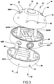
- the inspection vehicle 16 includes a vehicle housing 30 that is substantially cylindrical or spherical in construction with no significant protrusions or extensions that might otherwise be entangled with the internal components within the transformer 12.
- the vehicle housing 30 of the inspection vehicle 16 includes an upper cover 32 having a minimally extending nub 33, a middle section 34 and a lower cover 36.
- the nub 33 is sized so as to allow for grasping of the inspection vehicle 16 from within the transformer 12 by a tool or by an operator's hand.
- the nub 33 could have other shapes, such as a loop, to facilitate easy grasping, depending on the type of tool used to grasp the inspection vehicle 16.
- the cover 32, the middle section 34 and the cover 36 can be secured to one another with fastener apertures 40 that extend through at least the covers 32 and 36 so as to receive fasteners 42 to allow for attachment to the middle section 34.
- the fasteners 42 are maintained flush with the surface of the cover so as to minimize drag and prevent entanglement with internal components of the transformer 12.
- Other forms of mechanical fastening may be used, such as threaded engagement, press-fit, or mechanical clip or the like.
- the inspection vehicle 16 may only include two sections and in other embodiments the inspection vehicle 16 may include four or more sections.
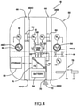
- Extending through the vehicle housing 30 are at least two pump flow channels designated generally by the numeral 44. These channels extend vertically and horizontally through the vehicle housing 30 and are configured so as to be sealed from the internal components of the vehicle housing 30.
- Each flow channel 44 provides a pair of ports 46. As shown in the drawings, numeric and alphabetic designations are provided so as to identify particular ports. For example, port 46A1 is at one end or side of the vehicle housing 30 while the opposite end of the flow channel 44 is designated by port 46A2. As such, the fluid maintained within the transformer can flow from one port 46A1 through and exit out port 46A2. In a similar manner, the oil may flow through port 46B1 and out through port 46B2.
- At least one sensor 48 is carried by the vehicle housing 30 and in some embodiments the sensor 48 is a camera.
- Other sensors can be used in some embodiments such as, by way of non-limiting examples, proximity sensors, acoustic sensors, electromagnetic sensors, voltage sensors, amperage sensors, pressure sensors and temperature sensors.
- the camera 48 is configured to receive and transmit images through a plurality of wavelength images of the internal components of the transformer 12. The wavelengths can include visible, infrared, or others as desired. These images allow an operator to monitor and inspect various components within the transformer 12.
- the vehicle housing 30 can include one or more light sources 52 which facilitate illumination of the area surrounding the inspection vehicle 16.
- the lights 52 can be light emitting diodes, but it will be appreciated that other illumination devices can be used.
- one or more of the lights 52 can include ultraviolet (UV) frequencies that may be used to cure UV hardened adhesives or the like.
- UV ultraviolet
- the illumination devices are oriented so as to illuminate the viewing area of the camera 48.
- the operator can control the intensity and wavelength of the light.
- a battery pack 54 is maintained within the inspection vehicle 16 so as to power the internal components such as the sensor 48, the lights 52 and a controller 60.
- the controller 60 operates the sensor 48 and lights 52 and also controls operation of a motor 62 and a pump 64 which are used in combination with each of the provided pump flow channels 44.
- the controller 60 maintains the necessary hardware and software to control operation of the connected components and maintain the ability to communicate with the computer 18 as well as with other devices.
- the controller 60 provides functionality in addition to controlling the motion of the inspection vehicle 16. For example, the controller 60 can provide for a data recording function so that a high-resolution, high speed video of the entire inspection area generated by the sensor 48 can be recorded and stored onboard by the storage device 68.
- On board storage may be used in instances where wireless streaming of the video is interrupted or the antenna transmission of the wireless signals has a lower than desired bandwidth.
- the sensor 48 may also be a thermal camera, a sonar sensor, a radar sensor, a three-dimensional vision sensor, or any combination of sensors.
- Each motor 62 is reversible so as to control the flow of fluid through the flow channels by the pump 64.
- each motor is operated independently of one another so as to control operation of the associated thruster pump 64 such that rotation of the pump 64 in one direction causes the fluid to flow through the flow channel 44 in a specified direction and thus assist in propelling the vehicle housing 30 in a desired direction.
- the pump 64 which may also be referred to as a thruster pump, is shown as being a propeller type configuration, but other configurations such as a paddle-type pump or gear pump could be utilized.
- a single motor may be used to generate a flow of fluid through more than one channel.
- the vehicle housing 30 could provide a single inlet and two or more outlets. Valves maintained within the vehicle housing 30 could be used to control and re-direct the internal flow of the fluid and, as a result, control movement of the vehicle housing 30 within the transformer tank or housing 13.
- the inspection vehicle 16 can traverse all areas of having sufficient space within the transformer 12.
- the inspection vehicle 16 is able to maintain an orientational stability while maneuvering in the transformer tank or housing 13. In other words, the inspection vehicle 16 is stable such that it will not move end-over-end while moving within the transformer tank or housing 13.
- the vehicle housing 30 of the inspection vehicle 16 provides for a center of gravity designated by the capital letter G.
- the inspection vehicle 16 components are designed so that the center of gravity G is lower than the center of the buoyant force of the inspection vehicle 16 designated by the capital letter F. As skilled artisans will appreciate, this enables the inspection vehicle 16 to be provided with stability during traversal motion.
- the vehicle housing 30 also carries a data storage device 68 which collects the data from the sensor 48 and is adequately sized to provide for storage of video or still images taken by a camera.
- the storage device 68 is connected to the controller 60 so as to provide for reliable transfer of the data from the sensor/camera 48 to the storage device 68. It will be appreciated that in some embodiments the storage device 68 is connected directly to the sensor 48 and the controller receives the data directly from the storage device 68.
- An antenna 70 is connected to the controller 60 for the purpose of transmitting data collected from the sensor 48 and also for sending and receiving control signals for controlling the motion and/or direction of the inspection vehicle 16 within the transformer 12. The antenna generates a wireless signal 72 that can be detected by the computer 18 or any intermediate device.
- a failure detection module 74 (designated as FD in Fig. 4 ) may be included in the controller so as to shut down the internal components within the inspection vehicle 16 if a system failure is detected. For example, if a low battery level is detected by the controller 60, the module 74 and the controller 60 can begin a controlled shutdown of the inspection vehicle 16 which would cause the inspection vehicle 16 to float to the surface due to its positive buoyancy. In another example, a loss of connection to the remote system could also trigger a shutdown.
- a borescope 76 may also be carried by the vehicle housing 30.
- One end of the borescope provides a camera 77 or other sensor connected to a retractable fiber-optic cable 78 which is connected at its opposite end to the controller 60.
- the camera 77 When in a retracted position the camera 77 is flush with the surface of the vehicle housing 30 so as to prevent entanglement with the components inside the transformer 12.
- the cable 78 When inspection of hard to view items is needed, such as the windings of the transformer 12, the cable 78 is extended while the inspection vehicle 16 is maintained in a stationary position. After images and other data are collected by the camera 77, the cable is retracted. As a result, the borescope 76 allows further detailed inspection of the transformer 12.
- the inspection vehicle 16 is configured so as to easily move around the obstacles within the transformer 12.
- the vehicle housing 30 is a cylindrical-shaped with sphere ends or sphere shaped configuration and is provided with a buoyant design so as to allow the inspection vehicle 16 to float to the top of the oil when it is powered off purposefully or accidentally.
- the inspection vehicle 16 is configured so as to allow for the thruster pumps 64 to move the inspection vehicle 16 around by selective actuation of each pump.
- the inspection vehicle 16 has four degrees of freedom or motion: X, Y, Z and rotation around Z. As a result, by controlling the direction of the pump thrusters 64, the inspection vehicle 16 can be easily moved.
- the transformer 12 has at least one transformer hole 80.
- the oil is inserted through any number of holes located in the top of the tank. Holes 80 may also be provided at the bottom of the tank to allow for the fluid to be drained.
- the holes 80 are provided with the appropriate plugs or caps. Accordingly, it will be appreciated that the size of the inspection vehicle 16 must be such that it can fit within the hole 80.
- the transformer 12 may be configured with a plurality of transmit signal receivers 82 mounted on the upper corners, edges or other areas of the transformer 12, or in nearby proximity to the transformer 12.
- the transmit signal receivers 82 receive the wireless signal 72 from the inspection vehicle 16 to determine the position of the inspection vehicle 16 in the transformer tank or housing 13.
- the receivers 82 use triangulation, based on the signals 72 received or other methodology, to determine a position of the inspection vehicle 16 in the transformer tank or housing 13.
- This position information is then transmitted by a signal 84 wirelessly, to the computer 18.
- the information collected by the sensor 48 such as the visual data, is transferred to the computer or other visual receiving device separately. In other words, the informational data generated by the sensor 48 is transmitted to the computer 18 through the fluid and the tank wall with the openings 80.
- a transceiver 85 may be inserted into the cooling oil tank through the service opening on the top of the transformer 12.
- the transceiver 85 is used to exchange data information from the sensor 48 and the camera 77, via the controller 60 to the computer 18; and motion control or maneuvering signals from the joystick 24 via the computer 18 to the controller 60 so as to operate the motors 62 and thrusters 64.
- the signal 84, transmitted by the receiver 82 is used by the computer 18 to provide a separate confirmation of the position of the inspection vehicle 16 within the transformer tank or housing 13.
- Wireless signals transmitted between inspection vehicle 16 and computer 18, and the respective transmitters, receivers and transceivers for the various purposes described herein can occur in a variety of manners, including electronic wireless signals of various frequencies, powers, and protocols.
- the communication between the inspection vehicle 16 and the base station (computer 18) can be supplemented with a repeater or relay station, but not all embodiments need include such devices.
- the manners of transmission between devices need not be identical in all embodiments.
- the transmitter and/or receiver used for broadcast of signals from the base station (computer 18) can transmit in power that ranges from 1W to 5W. Other power output levels may be employed in other embodiments.
- the base station transmitter can also transmit in frequencies that that range from about 300MHz to about 5GHz, and in some forms are at any of 300MHz, 400MHz, 433MHz, 2.4GHz, and 5GHz. Other frequencies may be employed in other embodiments. Transmission can occur using any variety of protocols/formats/modulation/etc. In one example, transmission from the base station can use digital radio communications such as that used for RC model cars/boats/airplanes/helicopters. The transmission can also occur as TCP/IP or UDP, it can occur over WiFi radios, serial communication over Bluetooth radios, etc. In one particular form, video transmissions can occur as streaming for a Wi-Fi camera over 2.4GHz.
- the transmitter and/or receiver of the inspection vehicle can transmit in power that ranges from 250mW to 3W. Other power output levels may be employed in other embodiments.
- the inspection vehicle can also transmit in frequencies that that range from about 300MHz to about 5GHz, and in some forms are at any of 300MHz, 400MHz, 433MHz, 2.4GHz, and 5GHz. Other frequencies may be employed in other embodiments. Transmission can occur using any variety of protocols/formats/modulation/etc. In one example, transmission from the inspection vehicle can use digital radio communications such as that used for RC model cars/boats/airplanes/helicopters. The transmission could be video over IP, and one embodiment of IP could be Wi-Fi/WLAN.
- the transmission can therefore occur as TCP/IP or UDP, it can occur over WiFi radios, serial communication over Bluetooth radios, etc.
- video transmissions can occur as streaming for a Wi-Fi camera over 4.2GHz.
- transmission techniques/approaches/protocols/frequencies/etc are contemplated herein.
- the computer 18 receives the position signals 84 and information signals 72 and in conjunction with the virtual image 20 correlates the received signals to the virtual image so as to allow an operator to monitor and control movement of the inspection vehicle 16. This allows the operator to inspect the internal components of the transformer 12 and pay particular attention to certain areas within the transformer 12 if needed.
- the image obtained can be matched with the corresponding site inside the actual transformer tank or housing 13. Based on the visual representation of the transformer image 20 and the virtual inspection vehicle 22 in relation to the image, an operator can manipulate the joystick 24 response.
- the computer 18 receives the movement signals from the joystick 24 and transmits those wirelessly to the antenna 72, whereupon the controller 60 implements internally maintained subroutines to control the pump thrusters 64 to generate the desired movement. This movement is monitored in real-time by the operator who can re-adjust the position of the inspection vehicle 16 as appropriate.
- the computer 18 can be connected to a network 86, such as the internet, so as to allow for the images or sensor data to be transferred to experts, who may be remotely located, designated by the block 88 so that their input can be provided to the operator so as to determine the nature and extent of the condition within the transformer 12 and then provide corrective action as needed.
- control of the inspection vehicle 16 can also be transferred to an expert, who may be remotely located.
- the expert would have another computer that can send control signals via a network to the local computer 18 that in turn sends signals to control the inspection vehicle 16 as described above.
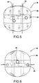
- Fig. 5 shows the utilization of two pumps under one control so as to move the inspection vehicle 16 in a Z direction.
- the Z axis thrusters have to run continuously.
- the Z thruster action can be controlled either manually by the operator or automatically by the controller.
- one control refers to operating two pumps to operate in conjunction with one another so that the fluid flow is uniformly in one direction or the other.
- FIG. 6 it can be seen that an X direction can be obtained by utilizing two pumps under two controls so as to allow for movement in an X direction.
- operation of "two pumps under two controls” means that the controller operates the pumps separately from one another.
- Fig. 7 it can be seen that the inspection vehicle 16 is movable along the Y direction wherein one pump is utilized under one control. It will be appreciated that Fig. 7 is a side view of Fig. 6 and at a slightly different elevation with respect to the X directional flow channels. As mentioned above, other embodiments could use different combinations of channels. For example, the three or four channels could exist in the Z direction.
- inventions could have one inlet port and two outlet ports for a channel, or vice versa, or even use a different number of inlets and outlets.
- the number of pumps could also vary. For example, one pump could be used to control the flow of fluid from one inlet port which is then output through four outlet ports.
- FIGs. 8A and 8B it can be seen that two pumps under one control allow for rotation of the inspection vehicle 16.
- Fig. 8A by directing the fluid flow in one direction through one channel and an opposite direction in another channel, counter-clockwise rotation can be obtained. By reversing the flows in both channels, clockwise rotation can be obtained as seen in Fig. 8B .
- Figs. 9A and 9B show rotation of the inspection vehicle 16 utilizing one pump under one control wherein the flow is directed from one side of the inspection vehicle 16 into the inspection vehicle 16 and then back out the same side. A corresponding flow is provided by the opposite side of the inspection vehicle 16 so as to provide for rotation about the Z axis. Reversing the flow provides a corresponding reversal of the rotation of the inspection vehicle 16 along the Z axis.
- the inspection vehicle 16 allows for visual and other inspection without draining transformer oil. This is accomplished by being able to drive the inspection vehicle 16 in the oil and perform visual or other inspection through the oil.
- the inspection vehicle 16 is constructed to be resistant to an oil environment and is properly sealed. Additionally, the inspection vehicle 16 is small enough to be put inside a transformer tank or housing 13 using existing service holes, e.g. those used for filling the transformer oil. As a result, it is not needed to unseal the transformer tank top completely.
- Another aspect is that the inspection vehicle 16 can be controlled from the outside of the transformer using a joystick 24 and computing device 18 which may also be used for presenting visual data from the sensor(s).
- the senor 48 utilizes a supporting light source carried by the inspection vehicle 16.
- Various wavelengths of light may be used (visible and/or non-visible light) for detailed inspection of the transformer 12 components inside.
- a remotely controlled arm that guides a thin fiber-optic camera head inside the transformer 12 winding block may also be used.
- Still another aspect of the inspection vehicle 16 is that all materials employed in the construction of the inspection vehicle 16 are oil compatible. This is to avoid any type of contamination introduced by the inspection vehicle 16, so that the transformer 12 can directly return to operation after the inspection of inspection vehicle 16 without oil treatment.
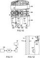
- Inspection vehicle 216 may be used in conjunction with in-situ inspection system 10 in addition to or in place of inspection vehicle 16.
- Inspection vehicle 216 includes a status interrogation system in the form of an ultrasound sensor 218.
- a status interrogation system is a system operative to capture data for contemporaneously or subsequently determining the status of a component, feature, system, subsystem or other aspect of the machine being inspected, e.g., of transformer 12, tank or housing 13, cooling liquid 14 and/or related components or features.
- Inspection vehicle 216 also includes many or most features described above with respect to inspection vehicle 16 in order to perform inspections, and performs most or all of the same functions as described above with respect to inspection vehicle 16.
- the features include but not limited to sensor 48, e.g., a camera; light sources 52; battery pack 54; controller 60; storage device 68; antenna 70 and other components and features for transmitting and receiving wireless signals, e.g., signals 72 and other wireless signals, to and from computer 18 through dielectric coolant liquid 14, and other components and features for wirelessly self-propelling around transformer 12, and performing inspection, data transmittal and/or maintenance of transformer 12 immersed in dielectric cooling liquid inside tank or housing 13.
- Computer 18 serves as a base station for wirelessly transmitting data, e.g., commands, to the inspection vehicle, e.g., for directing the actions of the inspection vehicle while immersed within dielectric cooling liquid 14, including propulsion and inspection activities; and for wirelessly receiving data transmitted from the inspection vehicle, e.g., position data, and sensor and status interrogation system data.
- the inspection vehicle 216 is constructed for wireless remote-controlled operation. In place of pumps 64, inspection vehicle 216 employs shrouded propellers 264, which provide, at least in part, propulsion for inspection vehicle 216 while immersed within cooling liquid 14.
- ultrasound sensor 218 is communicatively coupled to controller 60, and wirelessly to computer 18 via controller 60, e.g., and antenna 70.
- Ultrasound sensor 218 is operative to generate and detect ultrasound pulses, e.g., through a couplant, such as dielectric cooling liquid 14 in transformer tank or housing 13, and to record the echo time of each transmitted ultrasound pulse to determine wall thickness of structures associated with transformer 12 and/or tank or housing 13, e.g., when directed by controller 60, for example, in response to commands received from computer 18 via antenna 70.
- a couplant such as dielectric cooling liquid 14 in transformer tank or housing 13
- ultrasound sensor 218 is also operative to determine thicknesses of other materials and structures, including paint or other protective coating thickness, insulation thickness for one or more insulated structures or devices, and the thickness of any sediment build-up, e.g., at the bottom of tank or housing 13.
- ultrasound sensor 218 is a smart sensor operative to determine thickness based on echo time, and to transmit the thickness data to controller 60.
- controller 60 and/or computer 18 may be operative to determine the wall thickness of structures, features and sediment based on echo return time, e.g., based on the time between the sending of each ultrasound pulse and the receipt of the ultrasound pulse as reported by ultrasound sensor 218.
- echo return time e.g., based on the time between the sending of each ultrasound pulse and the receipt of the ultrasound pulse as reported by ultrasound sensor 218.
- inspection vehicle 216 in order to measure the local thickness T13 of the tank or housing 13 wall, inspection vehicle 216 propels itself toward the wall until ultrasound sensor 218 is touching the wall, after which time it emits the ultrasound pulses, detects the echoes and determines pulse return time to determine thickness. Likewise when measuring the thickness of other structures or features: inspection vehicle 216 propels itself toward the feature until ultrasound sensor 218 is touching the feature, at which time the interrogative pulses are sent and their echoes subsequently received in order to determine thickness based on the echo time.
- ultrasound sensor 218 and/or controller 60 and/or computer 18 may include and employ or access lookup tables, equations or other reference materials in order to determine thickness based on echo return time.
- the raw sensor data and/or thickness data may be wirelessly transmitted from inspection vehicle 216 to computer 18 via antenna 70.
- Camera 48 and light sources 52 may be employed to further investigate regions found using ultrasound sensor 218 to have an undesirable thickness, e.g., a reduced insulation thickness, a reduced wall thickness or an undesirable concentration of sediment.
- inspection vehicle 216 includes a status interrogation system in the form of microphones 220 constructed to detect partial discharge and potential breakdown of insulation within transformer 12.
- Microphones 220 are communicatively coupled to controller 60 and hence to base station or computer 18 via antenna 70.
- Partial discharge e.g., a partial discharge event, is a localized dielectric breakdown of a solid or fluid electrical insulation that may not, at least in the initial stages of failure, be visible.
- the partial discharge may be intermittent or may be continuous. The continued or repeated occurrence of partial discharge(s) over some duration typically leads to visibly apparent breakdown of insulation and damage to other structures, conductive or otherwise. If caught in the early stages, partial discharge can be addressed by remedial action prior to significant or substantial damage being done to the transformer.
- Inspection vehicle 216 includes eight (8) microphones 220 disposed about the surface of inspection vehicle 216, equally spaced apart circumferentially from each other. In other embodiments, other orientations and/or numbers of microphones may be employed. Preferably, at least three (3) microphones are employed, although some embodiments may have fewer than three microphones, and as few as one. More preferably, approximately seven (7) to eight (8) microphones are employed, although the number of microphones may vary with the needs of the particular application. In some embodiments, one or more acoustic cameras may be employed in addition to or in place of microphones 220.
- System 10 is constructed to triangulate the location of the partial discharge.
- a high voltage may be supplied to transformer 12, such as a normal or a peak operating voltage, but at low current, while inspection vehicle 216 is deployed within tank or housing 13, with microphones 220 immersed within dielectric liquid 14.
- the high voltage is selected to be representative of actual operating voltage so as to simulate normal operating conditions and to stimulate partial discharge at sites which would otherwise experience the partial discharge during normal operating conditions, whereas the reduced current reduces the damage caused by the partial discharges, and reduces the likelihood of damage to inspection vehicle 216. While the voltage is supplied to transformer 12, inspection vehicle 216 is directed past various portions of transformer 12, while "listening" for partial discharges using microphones 220.
- the "listening" may be performed while inspection vehicle 216 is in transit, whereas in other embodiments, inspection vehicle 216 may be paused at desired locations to listen for partial discharges.
- the location of the partial discharge is triangulated, e.g., based on the timing of the partial discharge induced sound waves reaching the locations of the different microphones 220 spaced apart around the circumference of inspection vehicle 216 (phase offset of the received signal as between the different microphones 220), as well as based on the amplitude difference as between the different microphones.
- the triangulation calculations are performed by controller 60.
- some or all of the microphone data may be wirelessly transmitted to computer 18, and the triangulation calculations may be performed by computer 18 in addition to or in place of controller 60. In some embodiments, only the triangulation results may be transmitted wirelessly to computer 18.
- inspection vehicle 216 may be maneuvered adjacent to the location of the partial discharge, and a single microphone 220 may be employed to confirm the exact location of the partial discharge if desired.
- a single microphone 220 may be employed to confirm the exact location of the partial discharge if desired.
- Once adjacent the partial discharge camera 48 and or one or more other status interrogation systems described herein may be employed to more closely observe or inspect the site for any damage or other physical signs of the partial discharge, e.g., in order to help decide upon remedial action.
- the power supplied to transformer 12 may be terminated, and then ultrasound sensor 218 may be employed to verify the thickness of insulation at the partial discharge site, or confirm other structural thickness parameters, or the presence and thickness of sediment that may be a contributing cause for the partial discharge.
- inspection vehicle 216 includes a status interrogation system in the form a magnetometer 222 (illustrated schematically).
- Magnetometer 222 is disposed inside of the nonmetallic inspection vehicle 216.
- magnetometer 222 is a multiaxis magnetometer. In other embodiments, magnetometer 222 may take other forms.
- magnetometer 222 is operative to sense magnetic field lines 224 along X, Y and Z axes, e.g., the X, Y and Z axes illustrated in FIG. 15 , and to detect variations in the magnetic field generated by transformer 12.
- magnetometer 222 is an orientation independent magnetometer, operative to obtain orientation independent measurement of magnetic fields within tank or housing 13, e.g., emanating from transformer 12.
- the sampling rate of magnetometer 222 may vary with the needs of the application.
- Measurement of the magnetic field, coupled with location information provided by inspection vehicle 216 can allow users to form a spatial map of the magnetic field profile within tank or housing 13 and transformer 12, e.g., by wirelessly transmitting the sensed magnetic field data to computer 18 and combining the data with a computer-aided design model of transformer 12 to form the spatial map. Any anomalous magnetic field measurements can be used to trigger an alert, potentially preventing damage or further damage within transformer 12.
- Magnetometer 222 is coupled to controller 60 and to base station computer 18 via antenna 70.
- Controller 60 is operative to direct magnetometer 222 to obtain magnetic field data at a desired sample rate.
- controller 60 is operative to wirelessly transmit via antenna 70 the magnetic field information to computer 18, which in some embodiments creates a spatial map of the magnetic field profile for visual comparison against a standard or baseline map.
- analysis of the magnetic flux lines measured by magnetometer may be performed in other manners.
- inspection vehicle 216 includes a status interrogation system in the form an aliquot collection system 228.
- Aliquot collection system 228 includes a compartmentalized bank of aliquot collection syringes 230 and a syringe plunger drive mechanism 232.
- Plunger drive mechanism 232 is communicatively coupled to controller 60, and hence to base station computer 18 via antenna 70. Plunger drive mechanism is operative to operate the aliquot collection syringes to obtain aliquot samples at desired locations, e.g., at the direction of controller 60 and/or computer 18.
- Aliquot collection system 228 allows inspection vehicle 216 to collect aliquots from different locations around transformer 12 in tank or housing 13, e.g., samples of dielectric cooling liquid 14. The aliquot samples obtained may be analyzed subsequently after removal of the aliquot collection syringes from inspection vehicle 216, allowing the use of sophisticated lab and analysis equipment that, for example, may not be locally available.
- sampling at different heights within tank or housing 13 and transformer 12 may aid in the analysis of particulate/sludge sedimentation.
- Guidance of inspection vehicle to obtain the aliquot samples may be performed manually or in conjunction with a computer aided design model of tank or housing 13 and transformer 12, allowing collection at desired locations.
- aliquot collection syringes 230 are clean, gas-tight and moisture-free syringes, which may prevent contamination of samples once taken.
- aliquot collection syringes 230 may be disposable. The type and nature of aliquot collection syringes 230 may vary with the needs of the application.
- Different forms or types of analytics may be employed, e.g., at an external laboratory, which may aid in assessing transformer health and in assessing the severity of various problems.
- paper (cellulose) insulation deterioration may be locally assessed in different locations around tank or housing 13 based on the use of the aliquot samples.
- liquid insulation overheating problems can be examined, and the level of severity can be estimated based on the use of the aliquot samples.
- suspected corona detection can be linked to its location of discharge, for example, if one or more aliquot samples indicates unusually elevated hydrogen levels.
- Dielectric breakdown tests, interfacial tension and neutralization numbers tests, among others, may be performed on the aliquot samples to indicated the presence of water, cellulose fibers or other particulate contaminants, e.g., which are known to vary at different depths. Also, localized aliquot collection can aid in locating arcing problems when used in conjunction with metals-in-oil analysis.
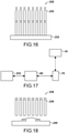
- inspection vehicle 216 includes a status interrogation system in the form a mechanical sampling system 236.
- Mechanical sampling system 236 is operative to extract mechanical samples from desired locations within tank or housing 13 and around transformer 12, and store the samples within sample collection bottles 238.
- Mechanical sampling system 236 includes a sample collection mechanism 240 schematically illustrated in FIG. 18 , which is operative to obtain samples, e.g., scrapings or scooping, from desired locations or features of transformer 12 or otherwise within tank or housing 13, for example, grit and sediment samples from the bottom of tank or housing 13, portions of insulation material, carbonization, coking, corrosion or other materials that may warrant further investigation.
- Sample collection mechanism 240 is communicatively coupled to controller 60, and hence to base station computer 18 via antenna 70. In one form, sample collection mechanism 240 is operative to perform mechanical sampling under the direction of computer 18, e.g., based on user input. In other embodiments, sample collection mechanism 240 is operative to perform mechanical sampling under the direction of controller 60 in addition to the direction of computer 18.
- inspection vehicle 216 includes a status interrogation system in the form a high sample rate chemical sensor 244.
- Chemical sensor 244 is operative to chemically analyze dielectric cooling liquid 14.
- chemical sensor 244 is operative to sense dissolved gaseous species, for example and without limitation, hydrogen, carbon dioxide and/or carbon monoxide.
- chemical sensor 244 may be operative to sense other dissolved gas species.
- chemical sensor 244 is also or alternatively operative to test for moisture level or other contaminant levels.
- a plurality of chemical sensors 244 may be employed, e.g., to test for different contaminant species.
- Chemical sensor 244 may be, for example, an optical sensor, an optical fiber sensor, or any other chemical sensor type.
- Chemical sensor 244 is communicatively coupled to controller 60, and hence to base station computer 18 via antenna 70. Inspection vehicle 216 is operative to wirelessly transmit chemical sensor 244 output to computer 18 via antenna 70. In one form, chemical sensor 244 is operative to test or sense for contaminants in cooling liquid 14 under the direction of computer 18, e.g., based on user input. In some embodiments, chemical sensor 244 may also or alternatively be operative to test or sense for contaminants automatically based on the location of inspection vehicle 216, e.g., under the direction of controller 60 and/or computer 18 with the aid of a computer-aided design model of transformer 12 and tank or housing 13.
- inspection vehicle 216 may be operated to perform more minute inspections around this location using chemical sensor 244 to "home in” on the source of the contamination, after which additional inspection procedures may be performed using camera 48 and/or other status interrogation systems, e.g., such as those disclosed herein.
- additional inspection procedures may be performed using camera 48 and/or other status interrogation systems, e.g., such as those disclosed herein.
- subsequent inspections using chemical sensor 244 may be performed, e.g., over the course of time.
- the sensor readings for each inspection may be stored in a memory, e.g., storage device 68 or within computer 18 to record the changes in sensor readings over time.
- controller 60 and/or computer 18 may send system alerts indicating abnormal readings, which in some embodiments may include the locations at which the abnormal readings were found. In some embodiments, a location-based mapping of regions within tank or housing 13 that have shown abnormal sensor reading may be generated, which may provide valuable information for use in determining the timing for the next transformer maintenance.
- inspection vehicle 216 includes a status interrogation system in the form an infrared sensor 248, e.g., an infrared thermometry sensor.
- Infrared sensor 248 is operative to sense the temperature within tank or housing 13, e.g., the temperature of transformer 12 and/or dielectric cooling liquid 14, at desired locations within tank or housing 13.
- Infrared sensor 248 is communicatively coupled to controller 60, and hence to base station computer 18 via antenna 70.
- Inspection vehicle 216 is operative to wirelessly transmit infrared sensor 248 data to computer 18 via antenna 70.
- infrared sensor 248 is operative to sense temperature, e.g., of cooling liquid 14, under the direction of computer 18, e.g., based on user input. In some embodiments, infrared sensor 248 may also or alternatively be operative to sense temperature automatically based on the location of inspection vehicle 216, e.g., under the direction of controller 60 and/or computer 18 with the aid of a computer-aided design model of transformer 12 and tank or housing 13.
- inspection vehicle 216 is operative to perform infrared thermometry mapping within tank or housing 13 using infrared sensor 248.
- inspection vehicle 216 may be maneuvered to desired locations, and the temperature sensed using infrared sensor 248.
- the sensor readings for each inspection may be stored in a memory, e.g., storage device 68 or within computer 18, and in some embodiments may be used to generate a heat profile within transformer 12 and tank or housing 13, allowing monitoring of excessive heating and fluctuations in heat profile that can lead to oil decomposition or degradation of paper insulation.
- Storage device 68 and/or computer 18 may record the changes in sensor readings over time. A heat map may thus be generated in some embodiments.
- Variation in the heat map over time may be used to provide an informative analysis of transformer health, particularly when used in conjunction with data from other status interrogation systems, e.g., described herein, such as aliquot collection system 228, mechanical sampling system 238 and chemical sensor 244.
- inspection vehicle 216 is autonomously guided using controller 60, for example, based on waypoints or other data stored in storage device 68, e.g., a computer-aided design model of transformer 12 and tank or housing 13, and/or that the actions of the status interrogation systems are autonomously operated and controlled by controller 60, e.g., based on the waypoint or other data stored in storage device 68.
Landscapes
- Physics & Mathematics (AREA)
- Engineering & Computer Science (AREA)
- General Physics & Mathematics (AREA)
- Power Engineering (AREA)
- Chemical & Material Sciences (AREA)
- Spectroscopy & Molecular Physics (AREA)
- Life Sciences & Earth Sciences (AREA)
- Health & Medical Sciences (AREA)
- High Energy & Nuclear Physics (AREA)
- General Engineering & Computer Science (AREA)
- Plasma & Fusion (AREA)
- Biochemistry (AREA)
- Pathology (AREA)
- General Chemical & Material Sciences (AREA)
- Food Science & Technology (AREA)
- Medicinal Chemistry (AREA)
- Analytical Chemistry (AREA)
- Chemical Kinetics & Catalysis (AREA)
- General Health & Medical Sciences (AREA)
- Immunology (AREA)
- Oil, Petroleum & Natural Gas (AREA)
- Condensed Matter Physics & Semiconductors (AREA)
- Arrangements For Transmission Of Measured Signals (AREA)
- Radiation Pyrometers (AREA)
- Testing Relating To Insulation (AREA)
- Testing Electric Properties And Detecting Electric Faults (AREA)
- Investigating Or Analyzing Materials By The Use Of Ultrasonic Waves (AREA)
- Testing Of Devices, Machine Parts, Or Other Structures Thereof (AREA)
Claims (16)
- Inspektionssystem zum Inspizieren eines flüssigkeitsgefüllten Transformators, aufweisend:ein Inspektionsfahrzeug (216), konstruiert zum drahtlosen ferngesteuerten Betrieb, wenn untergetaucht in einem dielektrischen flüssigen Medium (14), wobei das Inspektionsfahrzeug (216) selbst angetrieben ist;ein Steuergerät (60), das operativ ist zum Lenken von Aktivitäten des Inspektionsfahrzeugs (216); undmehrere Statusabfragesysteme, an dem Inspektionsfahrzeug (216) angeordnet, wobei die mehreren Statusabfragesysteme (218) operativ sind zum Erfassen von Inspektionsdaten bezüglich mehrerer an dem Transformator durchgeführter Inspektionsprozeduren;dadurch gekennzeichnet, dassdie mehreren Statusabfragesysteme ein Aliquot-Sammelsystem (228) enthalten, operativ zum Sammeln von Aliquot-Proben des dielektrischen flüssigen Mediums.
- Inspektionssystem nach Anspruch 1, wobei die mehreren Statusabfragesysteme weiter ein mechanisches Probennahmesystem (236) enthalten, operativ zum mechanischen Erhalten von Proben innerhalb des Transformators.
- Inspektionssystem nach Anspruch 1, wobei die mehreren Statusabfragesysteme weiter mindestens eines der Folgenden enthalten:i) einen chemischen Sensor (244), operativ zum Erfassen von Verunreinigungen in dem dielektrischen flüssigen Medium,ii) einen Infrarotsensor (248), operativ zum Erfassen einer Temperatur, undiii) einen Ultraschallsensor (218), operativ zum Messen einer Dicke,iv) ein Mikrofon, operativ zum Erfassen von mit einer Teilentladung assoziierten Schallwellen, undv) ein Magnetometer, operativ zum Quantifizieren eines Magnetfelds des Transformators.
- Inspektionssystem nach Anspruch 3, Option iv), wobei das Mikrofon mehrere an das Steuergerät gekoppelte Mikrofone ist, wobei das Steuergerät operativ ist zum Triangulieren eines Orts der Teilentladung.
- Inspektionssystem nach Anspruch 3, Option v), wobei das Magnetometer ein Mehrachsen-Magnetometer ist.
- Inspektionssystem nach einem vorhergehenden Anspruch, wobei das Steuergerät (60) ein Teil des Inspektionsfahrzeugs (216) ist und operativ zum autonomen Betreiben des Inspektionsfahrzeugs (216) und/oder der mehreren Statusabfragesysteme.
- Inspektionssystem nach einem der Ansprüche 1 bis 5, weiter aufweisend eine Basisstation, operativ zum drahtlosen Lenken der Aktivitäten der Inspektion, wobei das Steuergerät ein Teil der Basisstation ist.
- Inspektionssystem nach Anspruch 1 bis 6, weiter aufweisend eine Basisstation (18),
wobei das Steuergerät (60) an mindestens eines der Statusabfragesysteme gekoppelt ist und operativ zum drahtlosen Übertragen der erfassten Daten zu der Basisstation (18). - Inspektionssystem nach Anspruch 1 bis 8, wobei das Aliquot-Sammelsystem (228) eine aufgeteilte Bank von Aliquot-Sammelspritzen (230) und einen Spritzenkolben-Antriebsmechanismus (232) enthält.
- Verfahren zum Durchführen einer Inspektion eines Transformators, aufweisend:Bereitstellen mehrerer Statusabfragesysteme an einem Inspektionsfahrzeug (216), wobei die mehreren Statusabfragesysteme ein Aliquot-Sammelsystem (228) enthalten, operativ zum Sammeln von Aliquot-Proben eines dielektrischen flüssigen Mediums, während das Inspektionsfahrzeug in das dielektrische flüssige Medium eingetaucht ist, und wobei die mehreren Statusabfragesysteme operativ sind zum Erfassen von Inspektionsdaten bezüglich mehrerer an dem Transformator durchzuführender Inspektionsprozeduren;Eintauchen des Inspektionsfahrzeugs (216) in ein dielektrisches flüssiges Medium innerhalb eines Gehäuses des Transformators;Betreiben einer Basisstation (18) zum drahtlosen Lenken eines Manövrierens des Inspektionsfahrzeugs (216) innerhalb des Transformators und zum drahtlosen Lenken der mehreren Inspektionsprozeduren des Inspektionsfahrzeugs (216) unter Verwendung der mehreren Statusabfragesysteme, wenn in das dielektrische Medium eingetaucht.
- Das Verfahren nach Anspruch 10, wobei die mehreren Statusabfragesysteme einen Ultraschallsensor enthalten, weiter aufweisend das Messen einer Dicke, während das Inspektionsfahrzeug (216) in das dielektrische flüssige Medium eingetaucht ist, unter Verwendung des Ultraschallsensors.
- Verfahren nach Ansprüchen 10 oder 11, wobei die mehreren Statusabfragesysteme weiter ein Mikrofon enthalten, operativ zum Erfassen von mit einem Teilentladeereignis assoziierten Schallwellen, weiter aufweisend das Bestimmen eines Orts eines Teilentladeereignisses innerhalb des Gehäuses unter Verwendung des Mikrofons, während das Inspektionsfahrzeug in das dielektrische flüssige Medium eingetaucht ist.
- Verfahren nach einem der Ansprüche 10-12, wobei die mehreren Statusabfragesysteme weiter ein Magnetometer enthalten, weiter aufweisend das Erfassen einer Magnetfeldstärke in dem Transformator unter Verwendung des Magnetometers, während das Inspektionsfahrzeug in das dielektrische flüssige Medium eingetaucht ist.
- Verfahren nach einem der Ansprüche 10-13, wobei die mehreren Statusabfragesysteme weiter ein mechanisches Probennahmesystem enthalten, operativ zum mechanischen Sammeln von Proben innerhalb des Transformators, während das Inspektionsfahrzeug in das dielektrische flüssige Medium eingetaucht ist.
- Verfahren nach einem der Ansprüche 10-14, wobei die mehreren Statusabfragesysteme weiter einen chemischen Sensor enthalten, weiter aufweisend das Erfassen auf Verunreinigungen in dem dielektrischen flüssigen Medium unter Verwendung des chemischen Sensors, während das Inspektionsfahrzeug in das dielektrische flüssige Medium eingetaucht ist.
- Verfahren nach einem der Ansprüche 10-15, wobei die mehreren Statusabfragesysteme weiter einen Infrarotthermometriesensor enthalten, weiter aufweisend das Erfassen einer Temperatur unter Verwendung des Infrarotthermometriesensors, während das Inspektionsfahrzeug in das dielektrische flüssige Medium eingetaucht ist.
Applications Claiming Priority (2)
| Application Number | Priority Date | Filing Date | Title |
|---|---|---|---|
| US201662431323P | 2016-12-07 | 2016-12-07 | |
| PCT/IB2017/001628 WO2018104783A2 (en) | 2016-12-07 | 2017-12-06 | Systems and method for inspecting a machine |
Publications (2)
| Publication Number | Publication Date |
|---|---|
| EP3552213A2 EP3552213A2 (de) | 2019-10-16 |
| EP3552213B1 true EP3552213B1 (de) | 2022-02-09 |
Family
ID=61258563
Family Applications (1)
| Application Number | Title | Priority Date | Filing Date |
|---|---|---|---|
| EP17844604.3A Active EP3552213B1 (de) | 2016-12-07 | 2017-12-06 | System und verfahren zur inspektion einer maschine |
Country Status (5)
| Country | Link |
|---|---|
| US (1) | US11923096B2 (de) |
| EP (1) | EP3552213B1 (de) |
| JP (1) | JP6834002B2 (de) |
| CN (1) | CN110402468B (de) |
| WO (1) | WO2018104783A2 (de) |
Families Citing this family (3)
| Publication number | Priority date | Publication date | Assignee | Title |
|---|---|---|---|---|
| JP7357566B2 (ja) * | 2020-02-13 | 2023-10-06 | 三菱電機株式会社 | 部分放電検出システム |
| KR102296521B1 (ko) * | 2021-04-21 | 2021-09-10 | 박순세 | 합성수지관 제조장치 |
| CN114055495A (zh) * | 2021-11-30 | 2022-02-18 | 国网重庆市电力公司电力科学研究院 | 功能重构型变压器内部检测智能机器人 |
Citations (6)
| Publication number | Priority date | Publication date | Assignee | Title |
|---|---|---|---|---|
| US6104970A (en) * | 1998-02-17 | 2000-08-15 | Raytheon Company | Crawler inspection vehicle with precise mapping capability |
| US20060290779A1 (en) * | 2005-01-18 | 2006-12-28 | Reverte Carlos F | Autonomous inspector mobile platform |
| US20070125289A1 (en) * | 2005-10-12 | 2007-06-07 | Asfar Khaled R | Unmanned autonomous submarine |
| WO2014120568A1 (en) * | 2013-02-01 | 2014-08-07 | Abb Technology Ag | Device and method for transformer in-situ inspection |
| CN204359759U (zh) * | 2015-01-30 | 2015-05-27 | 杭州美卓自动化技术有限公司 | 一种油色谱混油装置 |
| JP5872127B1 (ja) * | 2015-07-17 | 2016-03-01 | 三菱電機株式会社 | 油入電気機器の異常診断方法 |
Family Cites Families (22)
| Publication number | Priority date | Publication date | Assignee | Title |
|---|---|---|---|---|
| US3505597A (en) * | 1967-12-13 | 1970-04-07 | Westinghouse Electric Corp | Corona testing apparatus including an oscilloscope and mechanical to electrical transducers having signal isolating means therebetween |
| BE756811A (fr) * | 1969-12-04 | 1971-03-01 | Ver Deutsche Metallwerke Ag | Procede de controle du diametre interieur de tubes |
| US3707673A (en) * | 1971-03-29 | 1972-12-26 | Westinghouse Electric Corp | Corona discharge detecting apparatus including gatable amplifiers controlled by flip-flop means |
| US3731752A (en) * | 1971-06-25 | 1973-05-08 | Kalium Chemicals Ltd | Magnetic detection and magnetometer system therefor |
| US3915646A (en) * | 1974-09-30 | 1975-10-28 | Cabot Corp | Method and means for quantitative analysis of sulfuric acid-containing gases |
| JPS6347678A (ja) * | 1986-08-18 | 1988-02-29 | Toshiba Corp | 部分放電検出装置 |
| JPH11326429A (ja) * | 1998-05-20 | 1999-11-26 | Toshiba Corp | 乾式絶縁機器の絶縁診断方法及びその装置 |
| AUPQ260599A0 (en) * | 1999-09-02 | 1999-09-23 | Transgrid | Partial discharge monitoring system for transformers |
| US6840121B2 (en) * | 2002-07-18 | 2005-01-11 | University Of Florida Reasearch Foundation, Inc. | Self-powered fluid sampler |
| US8532730B2 (en) * | 2006-10-04 | 2013-09-10 | Dexcom, Inc. | Analyte sensor |
| CN100545622C (zh) * | 2005-12-09 | 2009-09-30 | 国家海洋局第二海洋研究所 | 一种可控深海采水装置 |
| CN201382868Y (zh) * | 2009-02-17 | 2010-01-13 | 吴天尧 | 油罐全程定位采样装置 |
| CA2757715A1 (en) * | 2009-04-15 | 2010-10-21 | Dietmar Oberhoff | Ultrasonic testing system |
| CN101551434B (zh) * | 2009-05-13 | 2012-08-22 | 中南大学 | 基于超高频检测技术的变压器局部放电定位方法 |
| US20120256640A1 (en) * | 2011-04-07 | 2012-10-11 | Boris Leonid Sheikman | Apparatus and methods for use in determining the presence of materials entrained within a medium |
| CN102520324A (zh) * | 2011-12-27 | 2012-06-27 | 镇江市诚翔电器有限责任公司 | 一种中压智能开关柜绝缘在线监测系统与监测方法 |
| CN104316362A (zh) * | 2014-11-14 | 2015-01-28 | 成都蓝宇科维科技有限公司 | 一种旋转推注式水样采集器 |
| JP6246751B2 (ja) * | 2015-02-12 | 2017-12-13 | 株式会社日立製作所 | 絶縁劣化検出システム、絶縁劣化検出方法および絶縁劣化検出用センサ |
| CN204439417U (zh) * | 2015-03-13 | 2015-07-01 | 宁夏环境科学研究院(有限责任公司) | 一种多功能定深水位水质采样装置 |
| CN104931300B (zh) * | 2015-07-08 | 2018-01-09 | 浙江大学 | 定时海水采样装置 |
| US11877087B2 (en) * | 2015-08-19 | 2024-01-16 | NeoGenesys, Inc. | Methods and systems for remote monitoring of electrical equipment |
| CN105182141A (zh) * | 2015-09-30 | 2015-12-23 | 广州供电局有限公司电力试验研究院 | 变压器故障检测方法及系统 |
-
2017
- 2017-12-06 EP EP17844604.3A patent/EP3552213B1/de active Active
- 2017-12-06 WO PCT/IB2017/001628 patent/WO2018104783A2/en not_active Ceased
- 2017-12-06 CN CN201780086222.1A patent/CN110402468B/zh active Active
- 2017-12-06 JP JP2019530655A patent/JP6834002B2/ja active Active
-
2019
- 2019-06-07 US US16/434,682 patent/US11923096B2/en active Active
Patent Citations (6)
| Publication number | Priority date | Publication date | Assignee | Title |
|---|---|---|---|---|
| US6104970A (en) * | 1998-02-17 | 2000-08-15 | Raytheon Company | Crawler inspection vehicle with precise mapping capability |
| US20060290779A1 (en) * | 2005-01-18 | 2006-12-28 | Reverte Carlos F | Autonomous inspector mobile platform |
| US20070125289A1 (en) * | 2005-10-12 | 2007-06-07 | Asfar Khaled R | Unmanned autonomous submarine |
| WO2014120568A1 (en) * | 2013-02-01 | 2014-08-07 | Abb Technology Ag | Device and method for transformer in-situ inspection |
| CN204359759U (zh) * | 2015-01-30 | 2015-05-27 | 杭州美卓自动化技术有限公司 | 一种油色谱混油装置 |
| JP5872127B1 (ja) * | 2015-07-17 | 2016-03-01 | 三菱電機株式会社 | 油入電気機器の異常診断方法 |
Non-Patent Citations (1)
| Title |
|---|
| REFEREX, 1 January 2008 (2008-01-01), XP040426153 * |
Also Published As
| Publication number | Publication date |
|---|---|
| EP3552213A2 (de) | 2019-10-16 |
| JP6834002B2 (ja) | 2021-02-24 |
| JP2020504812A (ja) | 2020-02-13 |
| WO2018104783A2 (en) | 2018-06-14 |
| CN110402468B (zh) | 2024-03-22 |
| US11923096B2 (en) | 2024-03-05 |
| WO2018104783A3 (en) | 2018-08-16 |
| US20190287689A1 (en) | 2019-09-19 |
| CN110402468A (zh) | 2019-11-01 |
Similar Documents
| Publication | Publication Date | Title |
|---|---|---|
| US12163896B2 (en) | Device and method for transformer in-situ inspection | |
| US10844562B2 (en) | Deployment apparatus having a tether arm for an inspection vehicle | |
| US20190325668A1 (en) | Submersible inspection system | |
| US12066403B2 (en) | Systems, methods and apparatus for in-service tank inspections | |
| US10611447B2 (en) | Autonomous underwater system for a 4D environmental monitoring | |
| US11923096B2 (en) | Systems and methods for inspecting a machine | |
| US8417188B1 (en) | Systems and methods for inspection and communication in liquid petroleum product | |
| US20250060065A1 (en) | Inspection robot | |
| US11087895B2 (en) | Liquid tank inspection including device for launching submersible | |
| EP3552212B1 (de) | Inspektionsfahrzeug mit wartungswerkzeugen | |
| US20200218285A1 (en) | Tether for an inspection vehicle | |
| US11360120B2 (en) | System and method for handling and charting data obtained by an inspection vehicle | |
| US10017864B2 (en) | Automated tank cathodic protection/corrosion monitoring system | |
| CN120161122B (zh) | 一种基于管道机器人的管道探伤检测方法及系统 |
Legal Events
| Date | Code | Title | Description |
|---|---|---|---|
| STAA | Information on the status of an ep patent application or granted ep patent |
Free format text: STATUS: UNKNOWN |
|
| STAA | Information on the status of an ep patent application or granted ep patent |
Free format text: STATUS: THE INTERNATIONAL PUBLICATION HAS BEEN MADE |
|
| PUAI | Public reference made under article 153(3) epc to a published international application that has entered the european phase |
Free format text: ORIGINAL CODE: 0009012 |
|
| STAA | Information on the status of an ep patent application or granted ep patent |
Free format text: STATUS: REQUEST FOR EXAMINATION WAS MADE |
|
| 17P | Request for examination filed |
Effective date: 20190708 |
|
| AK | Designated contracting states |
Kind code of ref document: A2 Designated state(s): AL AT BE BG CH CY CZ DE DK EE ES FI FR GB GR HR HU IE IS IT LI LT LU LV MC MK MT NL NO PL PT RO RS SE SI SK SM TR |
|
| AX | Request for extension of the european patent |
Extension state: BA ME |
|
| RIN1 | Information on inventor provided before grant (corrected) |
Inventor name: RAKUFF, STEFAN Inventor name: ROSSANO, GREGORY, F. Inventor name: ZHANG, BIAO Inventor name: NICHOLAS, NOLAN, W. Inventor name: CHEIM, LUIZ, V. Inventor name: PATEL, POORVI Inventor name: LASKO, DANIEL Inventor name: SHAH, HARSHANG Inventor name: SHARMA, SAUMYA Inventor name: EAKINS, WILLIAM, JOHN Inventor name: COLE, GREGORY Inventor name: FUHLBRIGGE, THOMAS, A. Inventor name: MORATO, CARLOS Inventor name: CHOI, SANGUEN |
|
| DAV | Request for validation of the european patent (deleted) | ||
| DAX | Request for extension of the european patent (deleted) | ||
| STAA | Information on the status of an ep patent application or granted ep patent |
Free format text: STATUS: EXAMINATION IS IN PROGRESS |
|
| PUAG | Search results despatched under rule 164(2) epc together with communication from examining division |
Free format text: ORIGINAL CODE: 0009017 |
|
| 17Q | First examination report despatched |
Effective date: 20200618 |
|
| B565 | Issuance of search results under rule 164(2) epc |
Effective date: 20200618 |
|
| RIC1 | Information provided on ipc code assigned before grant |
Ipc: H01F 27/12 20060101ALI20200616BHEP Ipc: G21C 17/013 20060101AFI20200616BHEP Ipc: B62D 55/32 20060101ALI20200616BHEP |
|
| RAP1 | Party data changed (applicant data changed or rights of an application transferred) |
Owner name: ABB POWER GRIDS SWITZERLAND AG |
|
| GRAP | Despatch of communication of intention to grant a patent |
Free format text: ORIGINAL CODE: EPIDOSNIGR1 |
|
| STAA | Information on the status of an ep patent application or granted ep patent |
Free format text: STATUS: GRANT OF PATENT IS INTENDED |
|
| INTG | Intention to grant announced |
Effective date: 20211011 |
|
| GRAS | Grant fee paid |
Free format text: ORIGINAL CODE: EPIDOSNIGR3 |
|
| GRAA | (expected) grant |
Free format text: ORIGINAL CODE: 0009210 |
|
| STAA | Information on the status of an ep patent application or granted ep patent |
Free format text: STATUS: THE PATENT HAS BEEN GRANTED |
|
| RAP3 | Party data changed (applicant data changed or rights of an application transferred) |
Owner name: HITACHI ENERGY SWITZERLAND AG |
|
| RIN1 | Information on inventor provided before grant (corrected) |
Inventor name: CHOI, SANGUEN Inventor name: ROSSANO, GREGORY, F. Inventor name: NICHOLAS, NOLAN, W. Inventor name: SHARMA, SAUMYA Inventor name: RAKUFF, STEFAN Inventor name: PATEL, POORVI Inventor name: CHEIM, LUIZ, V. Inventor name: ZHANG, BIAO Inventor name: MORATO, CARLOS Inventor name: FUHLBRIGGE, THOMAS, A. Inventor name: SHAH, HARSHANG Inventor name: LASKO, DANIEL Inventor name: EAKINS, WILLIAM, JOHN Inventor name: COLE, GREGORY |
|
| AK | Designated contracting states |
Kind code of ref document: B1 Designated state(s): AL AT BE BG CH CY CZ DE DK EE ES FI FR GB GR HR HU IE IS IT LI LT LU LV MC MK MT NL NO PL PT RO RS SE SI SK SM TR |
|
| REG | Reference to a national code |
Ref country code: GB Ref legal event code: FG4D |
|
| REG | Reference to a national code |
Ref country code: CH Ref legal event code: EP Ref country code: AT Ref legal event code: REF Ref document number: 1468011 Country of ref document: AT Kind code of ref document: T Effective date: 20220215 |
|
| REG | Reference to a national code |
Ref country code: IE Ref legal event code: FG4D |
|
| REG | Reference to a national code |
Ref country code: DE Ref legal event code: R096 Ref document number: 602017053259 Country of ref document: DE |
|
| REG | Reference to a national code |
Ref country code: LT Ref legal event code: MG9D |
|
| REG | Reference to a national code |
Ref country code: NL Ref legal event code: MP Effective date: 20220209 |
|
| REG | Reference to a national code |
Ref country code: AT Ref legal event code: MK05 Ref document number: 1468011 Country of ref document: AT Kind code of ref document: T Effective date: 20220209 |
|
| PG25 | Lapsed in a contracting state [announced via postgrant information from national office to epo] |
Ref country code: SE Free format text: LAPSE BECAUSE OF FAILURE TO SUBMIT A TRANSLATION OF THE DESCRIPTION OR TO PAY THE FEE WITHIN THE PRESCRIBED TIME-LIMIT Effective date: 20220209 Ref country code: RS Free format text: LAPSE BECAUSE OF FAILURE TO SUBMIT A TRANSLATION OF THE DESCRIPTION OR TO PAY THE FEE WITHIN THE PRESCRIBED TIME-LIMIT Effective date: 20220209 Ref country code: PT Free format text: LAPSE BECAUSE OF FAILURE TO SUBMIT A TRANSLATION OF THE DESCRIPTION OR TO PAY THE FEE WITHIN THE PRESCRIBED TIME-LIMIT Effective date: 20220609 Ref country code: NO Free format text: LAPSE BECAUSE OF FAILURE TO SUBMIT A TRANSLATION OF THE DESCRIPTION OR TO PAY THE FEE WITHIN THE PRESCRIBED TIME-LIMIT Effective date: 20220509 Ref country code: NL Free format text: LAPSE BECAUSE OF FAILURE TO SUBMIT A TRANSLATION OF THE DESCRIPTION OR TO PAY THE FEE WITHIN THE PRESCRIBED TIME-LIMIT Effective date: 20220209 Ref country code: LT Free format text: LAPSE BECAUSE OF FAILURE TO SUBMIT A TRANSLATION OF THE DESCRIPTION OR TO PAY THE FEE WITHIN THE PRESCRIBED TIME-LIMIT Effective date: 20220209 Ref country code: HR Free format text: LAPSE BECAUSE OF FAILURE TO SUBMIT A TRANSLATION OF THE DESCRIPTION OR TO PAY THE FEE WITHIN THE PRESCRIBED TIME-LIMIT Effective date: 20220209 Ref country code: ES Free format text: LAPSE BECAUSE OF FAILURE TO SUBMIT A TRANSLATION OF THE DESCRIPTION OR TO PAY THE FEE WITHIN THE PRESCRIBED TIME-LIMIT Effective date: 20220209 Ref country code: BG Free format text: LAPSE BECAUSE OF FAILURE TO SUBMIT A TRANSLATION OF THE DESCRIPTION OR TO PAY THE FEE WITHIN THE PRESCRIBED TIME-LIMIT Effective date: 20220509 |
|
| PG25 | Lapsed in a contracting state [announced via postgrant information from national office to epo] |
Ref country code: PL Free format text: LAPSE BECAUSE OF FAILURE TO SUBMIT A TRANSLATION OF THE DESCRIPTION OR TO PAY THE FEE WITHIN THE PRESCRIBED TIME-LIMIT Effective date: 20220209 Ref country code: LV Free format text: LAPSE BECAUSE OF FAILURE TO SUBMIT A TRANSLATION OF THE DESCRIPTION OR TO PAY THE FEE WITHIN THE PRESCRIBED TIME-LIMIT Effective date: 20220209 Ref country code: GR Free format text: LAPSE BECAUSE OF FAILURE TO SUBMIT A TRANSLATION OF THE DESCRIPTION OR TO PAY THE FEE WITHIN THE PRESCRIBED TIME-LIMIT Effective date: 20220510 Ref country code: FI Free format text: LAPSE BECAUSE OF FAILURE TO SUBMIT A TRANSLATION OF THE DESCRIPTION OR TO PAY THE FEE WITHIN THE PRESCRIBED TIME-LIMIT Effective date: 20220209 Ref country code: AT Free format text: LAPSE BECAUSE OF FAILURE TO SUBMIT A TRANSLATION OF THE DESCRIPTION OR TO PAY THE FEE WITHIN THE PRESCRIBED TIME-LIMIT Effective date: 20220209 |
|
| PG25 | Lapsed in a contracting state [announced via postgrant information from national office to epo] |
Ref country code: IS Free format text: LAPSE BECAUSE OF FAILURE TO SUBMIT A TRANSLATION OF THE DESCRIPTION OR TO PAY THE FEE WITHIN THE PRESCRIBED TIME-LIMIT Effective date: 20220609 |
|
| PG25 | Lapsed in a contracting state [announced via postgrant information from national office to epo] |
Ref country code: SM Free format text: LAPSE BECAUSE OF FAILURE TO SUBMIT A TRANSLATION OF THE DESCRIPTION OR TO PAY THE FEE WITHIN THE PRESCRIBED TIME-LIMIT Effective date: 20220209 Ref country code: SK Free format text: LAPSE BECAUSE OF FAILURE TO SUBMIT A TRANSLATION OF THE DESCRIPTION OR TO PAY THE FEE WITHIN THE PRESCRIBED TIME-LIMIT Effective date: 20220209 Ref country code: RO Free format text: LAPSE BECAUSE OF FAILURE TO SUBMIT A TRANSLATION OF THE DESCRIPTION OR TO PAY THE FEE WITHIN THE PRESCRIBED TIME-LIMIT Effective date: 20220209 Ref country code: EE Free format text: LAPSE BECAUSE OF FAILURE TO SUBMIT A TRANSLATION OF THE DESCRIPTION OR TO PAY THE FEE WITHIN THE PRESCRIBED TIME-LIMIT Effective date: 20220209 Ref country code: DK Free format text: LAPSE BECAUSE OF FAILURE TO SUBMIT A TRANSLATION OF THE DESCRIPTION OR TO PAY THE FEE WITHIN THE PRESCRIBED TIME-LIMIT Effective date: 20220209 Ref country code: CZ Free format text: LAPSE BECAUSE OF FAILURE TO SUBMIT A TRANSLATION OF THE DESCRIPTION OR TO PAY THE FEE WITHIN THE PRESCRIBED TIME-LIMIT Effective date: 20220209 |
|
| REG | Reference to a national code |
Ref country code: DE Ref legal event code: R097 Ref document number: 602017053259 Country of ref document: DE |
|
| PG25 | Lapsed in a contracting state [announced via postgrant information from national office to epo] |
Ref country code: AL Free format text: LAPSE BECAUSE OF FAILURE TO SUBMIT A TRANSLATION OF THE DESCRIPTION OR TO PAY THE FEE WITHIN THE PRESCRIBED TIME-LIMIT Effective date: 20220209 |
|
| PLBE | No opposition filed within time limit |
Free format text: ORIGINAL CODE: 0009261 |
|
| STAA | Information on the status of an ep patent application or granted ep patent |
Free format text: STATUS: NO OPPOSITION FILED WITHIN TIME LIMIT |
|
| 26N | No opposition filed |
Effective date: 20221110 |
|
| PG25 | Lapsed in a contracting state [announced via postgrant information from national office to epo] |
Ref country code: SI Free format text: LAPSE BECAUSE OF FAILURE TO SUBMIT A TRANSLATION OF THE DESCRIPTION OR TO PAY THE FEE WITHIN THE PRESCRIBED TIME-LIMIT Effective date: 20220209 |
|
| P01 | Opt-out of the competence of the unified patent court (upc) registered |
Effective date: 20230527 |
|
| PG25 | Lapsed in a contracting state [announced via postgrant information from national office to epo] |
Ref country code: IT Free format text: LAPSE BECAUSE OF FAILURE TO SUBMIT A TRANSLATION OF THE DESCRIPTION OR TO PAY THE FEE WITHIN THE PRESCRIBED TIME-LIMIT Effective date: 20220209 |
|
| REG | Reference to a national code |
Ref country code: CH Ref legal event code: PL |
|
| REG | Reference to a national code |
Ref country code: BE Ref legal event code: MM Effective date: 20221231 |
|
| PG25 | Lapsed in a contracting state [announced via postgrant information from national office to epo] |
Ref country code: LU Free format text: LAPSE BECAUSE OF NON-PAYMENT OF DUE FEES Effective date: 20221206 |
|
| PG25 | Lapsed in a contracting state [announced via postgrant information from national office to epo] |
Ref country code: LI Free format text: LAPSE BECAUSE OF NON-PAYMENT OF DUE FEES Effective date: 20221231 Ref country code: IE Free format text: LAPSE BECAUSE OF NON-PAYMENT OF DUE FEES Effective date: 20221206 Ref country code: CH Free format text: LAPSE BECAUSE OF NON-PAYMENT OF DUE FEES Effective date: 20221231 |
|
| PG25 | Lapsed in a contracting state [announced via postgrant information from national office to epo] |
Ref country code: BE Free format text: LAPSE BECAUSE OF NON-PAYMENT OF DUE FEES Effective date: 20221231 |
|
| PG25 | Lapsed in a contracting state [announced via postgrant information from national office to epo] |
Ref country code: HU Free format text: LAPSE BECAUSE OF FAILURE TO SUBMIT A TRANSLATION OF THE DESCRIPTION OR TO PAY THE FEE WITHIN THE PRESCRIBED TIME-LIMIT; INVALID AB INITIO Effective date: 20171206 |
|
| REG | Reference to a national code |
Ref country code: DE Ref legal event code: R081 Ref document number: 602017053259 Country of ref document: DE Owner name: HITACHI ENERGY LTD, CH Free format text: FORMER OWNER: HITACHI ENERGY SWITZERLAND AG, BADEN, CH |
|
| PG25 | Lapsed in a contracting state [announced via postgrant information from national office to epo] |
Ref country code: CY Free format text: LAPSE BECAUSE OF FAILURE TO SUBMIT A TRANSLATION OF THE DESCRIPTION OR TO PAY THE FEE WITHIN THE PRESCRIBED TIME-LIMIT Effective date: 20220209 |
|
| PG25 | Lapsed in a contracting state [announced via postgrant information from national office to epo] |
Ref country code: MK Free format text: LAPSE BECAUSE OF FAILURE TO SUBMIT A TRANSLATION OF THE DESCRIPTION OR TO PAY THE FEE WITHIN THE PRESCRIBED TIME-LIMIT Effective date: 20220209 |
|
| PG25 | Lapsed in a contracting state [announced via postgrant information from national office to epo] |
Ref country code: MC Free format text: LAPSE BECAUSE OF FAILURE TO SUBMIT A TRANSLATION OF THE DESCRIPTION OR TO PAY THE FEE WITHIN THE PRESCRIBED TIME-LIMIT Effective date: 20220209 |
|
| PG25 | Lapsed in a contracting state [announced via postgrant information from national office to epo] |
Ref country code: MC Free format text: LAPSE BECAUSE OF FAILURE TO SUBMIT A TRANSLATION OF THE DESCRIPTION OR TO PAY THE FEE WITHIN THE PRESCRIBED TIME-LIMIT Effective date: 20220209 |
|
| REG | Reference to a national code |
Ref country code: GB Ref legal event code: 732E Free format text: REGISTERED BETWEEN 20240718 AND 20240724 |
|
| PG25 | Lapsed in a contracting state [announced via postgrant information from national office to epo] |
Ref country code: MT Free format text: LAPSE BECAUSE OF FAILURE TO SUBMIT A TRANSLATION OF THE DESCRIPTION OR TO PAY THE FEE WITHIN THE PRESCRIBED TIME-LIMIT Effective date: 20220209 |
|
| REG | Reference to a national code |
Ref country code: DE Ref legal event code: R082 Ref document number: 602017053259 Country of ref document: DE Representative=s name: DENNEMEYER & ASSOCIATES RECHTSANWALTSGESELLSCH, DE |
|
| PG25 | Lapsed in a contracting state [announced via postgrant information from national office to epo] |
Ref country code: TR Free format text: LAPSE BECAUSE OF FAILURE TO SUBMIT A TRANSLATION OF THE DESCRIPTION OR TO PAY THE FEE WITHIN THE PRESCRIBED TIME-LIMIT Effective date: 20220209 |
|
| PGFP | Annual fee paid to national office [announced via postgrant information from national office to epo] |
Ref country code: DE Payment date: 20251211 Year of fee payment: 9 |
|
| PGFP | Annual fee paid to national office [announced via postgrant information from national office to epo] |
Ref country code: GB Payment date: 20251219 Year of fee payment: 9 |
|
| PGFP | Annual fee paid to national office [announced via postgrant information from national office to epo] |
Ref country code: FR Payment date: 20251229 Year of fee payment: 9 |