EP3551835B1 - Wellhead systems and methods - Google Patents
Wellhead systems and methods Download PDFInfo
- Publication number
- EP3551835B1 EP3551835B1 EP17879820.3A EP17879820A EP3551835B1 EP 3551835 B1 EP3551835 B1 EP 3551835B1 EP 17879820 A EP17879820 A EP 17879820A EP 3551835 B1 EP3551835 B1 EP 3551835B1
- Authority
- EP
- European Patent Office
- Prior art keywords
- wellhead
- sensor
- component
- signal
- hanger
- Prior art date
- Legal status (The legal status is an assumption and is not a legal conclusion. Google has not performed a legal analysis and makes no representation as to the accuracy of the status listed.)
- Active
Links
Images


Classifications
-
- E—FIXED CONSTRUCTIONS
- E21—EARTH OR ROCK DRILLING; MINING
- E21B—EARTH OR ROCK DRILLING; OBTAINING OIL, GAS, WATER, SOLUBLE OR MELTABLE MATERIALS OR A SLURRY OF MINERALS FROM WELLS
- E21B43/00—Methods or apparatus for obtaining oil, gas, water, soluble or meltable materials or a slurry of minerals from wells
- E21B43/02—Subsoil filtering
- E21B43/10—Setting of casings, screens, liners or the like in wells
-
- E—FIXED CONSTRUCTIONS
- E21—EARTH OR ROCK DRILLING; MINING
- E21B—EARTH OR ROCK DRILLING; OBTAINING OIL, GAS, WATER, SOLUBLE OR MELTABLE MATERIALS OR A SLURRY OF MINERALS FROM WELLS
- E21B33/00—Sealing or packing boreholes or wells
- E21B33/02—Surface sealing or packing
- E21B33/03—Well heads; Setting-up thereof
- E21B33/035—Well heads; Setting-up thereof specially adapted for underwater installations
- E21B33/0355—Control systems, e.g. hydraulic, pneumatic, electric, acoustic, for submerged well heads
-
- E—FIXED CONSTRUCTIONS
- E21—EARTH OR ROCK DRILLING; MINING
- E21B—EARTH OR ROCK DRILLING; OBTAINING OIL, GAS, WATER, SOLUBLE OR MELTABLE MATERIALS OR A SLURRY OF MINERALS FROM WELLS
- E21B33/00—Sealing or packing boreholes or wells
- E21B33/02—Surface sealing or packing
- E21B33/03—Well heads; Setting-up thereof
- E21B33/04—Casing heads; Suspending casings or tubings in well heads
-
- E—FIXED CONSTRUCTIONS
- E21—EARTH OR ROCK DRILLING; MINING
- E21B—EARTH OR ROCK DRILLING; OBTAINING OIL, GAS, WATER, SOLUBLE OR MELTABLE MATERIALS OR A SLURRY OF MINERALS FROM WELLS
- E21B47/00—Survey of boreholes or wells
- E21B47/09—Locating or determining the position of objects in boreholes or wells, e.g. the position of an extending arm; Identifying the free or blocked portions of pipes
- E21B47/092—Locating or determining the position of objects in boreholes or wells, e.g. the position of an extending arm; Identifying the free or blocked portions of pipes by detecting magnetic anomalies
-
- E—FIXED CONSTRUCTIONS
- E21—EARTH OR ROCK DRILLING; MINING
- E21B—EARTH OR ROCK DRILLING; OBTAINING OIL, GAS, WATER, SOLUBLE OR MELTABLE MATERIALS OR A SLURRY OF MINERALS FROM WELLS
- E21B47/00—Survey of boreholes or wells
- E21B47/09—Locating or determining the position of objects in boreholes or wells, e.g. the position of an extending arm; Identifying the free or blocked portions of pipes
- E21B47/095—Locating or determining the position of objects in boreholes or wells, e.g. the position of an extending arm; Identifying the free or blocked portions of pipes by detecting an acoustic anomalies, e.g. using mud-pressure pulses
Definitions
- Hydrocarbon drilling and production systems require various components to access and extract hydrocarbons from subterranean earthen formations.
- Such systems generally include a wellhead assembly through which the hydrocarbons, such as oil and natural gas, are extracted.
- the wellhead assembly may include a variety of components, such as valves, fluid conduits, controls, casings, hangers, and the like to control drilling and/or extraction operations.
- hangers such as tubing or casing hangers, may be used to suspend strings (e.g., piping for various fluid flows into and out of the well) in the well.
- Such hangers may be disposed or received in a housing, spool, or bowl.
- the hangers provide sealing to seal the interior of the wellhead assembly and strings from pressure inside the wellhead assembly.
- an initial or calibrating run i.e., a "dummy run" of equipment into the wellhead must be made where a mark is placed on a landing joint corresponding to the landing position of the equipment run into the wellhead. Subsequently, the wellhead is rerun into the wellhead and the mark made on the landing joint is used to determine if the equipment is properly landed within the wellhead.
- US2007/0039738 shows a wellhead with a set of circumferential grooves in an internal surface.
- a tubing hanger to be inserted in the wellhead carries suspension dogs which can be pushed outwards to engage the grooves and hold the tubing hanger in place.
- An axial position transmitter on a running tool is detected by a receiver on a riser above the well head.
- an electrical circuit supplied by a controller at the surface is completed when a conductor carried by the tubing attached to the tubing hanger comes into contact with the wellhead and casing extending down from the wellhead.
- US 2016/0090802 shows a tool carrying a light source which indicates position when the light shines through an aperture in a wellhead component.
- US2011/02533889 describes a landing assembly which can be placed in a wellhead by means of a tool
- a wellhead system comprises a wellhead with a landing shoulder therein and a wellhead component to be installed in the wellhead at a predetermined aligned position in the wellhead, the wellhead component comprising a position indicator disposed in an outer surface of the wellhead component, and the wellhead comprising a position sensor configured to transmit a position signal in response to the position indicator contacting the landing shoulder of the wellhead as the wellhead component enters into a predetermined aligned position in the wellhead.
- the wellhead component comprises a tubing or casing hanger.
- the predetermined aligned position of the tubing or casing hanger comprises a position where a landing shoulder of the tubing or casing hanger physically engages a landing shoulder of the wellhead.
- the wellhead component comprises a bowl and a locking ring configured to releasably couple the bowl to the wellhead, wherein the bowl comprises a landing shoulder.
- the predetermined aligned position of the bowl comprises a position where the locking ring is aligned with a locking groove disposed in the inner surface of the wellhead.
- the position indicator comprises a magnetic member and the position sensor comprises a magnetic sensor.
- the position indicator comprises an acoustic signal generator and the position sensor comprises an acoustic sensor.
- the acoustic signal generator comprises a shear pin configured to a shear a terminal end thereof in response to the wellhead component entering into the predetermined aligned position.
- the wellhead system further comprises a signal transmitter in signal communication with the position sensor, wherein the signal transmitter is configured to transmit the position signal in real-time from the position sensor to a location distal the wellhead system.
- An embodiment of a wellhead system comprises a wellhead comprising a bore, and a wellbore monitoring assembly coupled to the wellhead, wherein the wellbore monitoring assembly comprises a sensor package disposed in a sensor housing, and a window disposed in a receptacle of the wellhead.
- the sensor package is configured to monitor conditions in the bore of the wellhead via the window disposed in the wellhead.
- the window comprises a sapphire glass material.
- the wellhead system further comprises a sealing interface disposed between the window and the receptacle of the wellhead, wherein the sealing interface comprises a primary seal between the bore of the wellhead and the surrounding environment, a gasket disposed between the sensor housing and an outer surface of the wellhead, wherein the gasket comprises a secondary seal between the bore of the wellhead and the surrounding environment.
- the sensor package comprises a temperature sensor and a pressure sensor.
- the wellhead system further comprises a signal transmitter in signal communication with the sensor package, wherein the signal transmitter is configured to transmit a sensor signal from the sensor package in real-time to a location distal the wellhead system.
- a method of landing a wellhead component in a wellhead with a landing shoulder therein, wherein the wellhead component comprises a position indicator comprises disposing the wellhead component in a bore of the wellhead, disposing the wellhead component in a predetermined aligned position in the bore of the wellhead, wherein the position indicator is disposed in an outer surface of the wellhead component and contacts the landing shoulder of the wellhead as the wellhead component enters into the predetermined aligned position in the wellhead, the wellhead comprises a position sensor and the method comprises transmitting a position signal from a position sensor in response to the position indicator contacting the landing shoulder of the wellhead on disposing the wellhead component in the predetermined aligned position.
- the method further comprises transmitting the position signal in response to physically engaging a landing shoulder of the wellhead component with a landing shoulder of the wellhead. In some embodiments, the method further comprises transmitting the position signal in response to aligning a locking ring with a locking groove disposed in an inner surface of the wellhead. In certain embodiments, the method further comprises transmitting the position signal in response to an acoustic signal generator coupled to the wellhead component generating an acoustic position signal. In certain embodiments, the method further comprises transmitting the position signal in response to aligning a magnetic member of the wellhead component with the position sensor.
- Figure 1 is a schematic diagram showing an embodiment of a well system 10 having a central or longitudinal axis 15.
- the well system 10 can be configured to extract various minerals and natural resources, including hydrocarbons (e.g., oil and/or natural gas), or configured to inject substances into an earthen surface 4 and an earthen formation 6 via a well or wellbore 8.
- the well system 10 is land-based, such that the surface 4 is land surface, or subsea, such that the surface 4 is the seal floor.
- the system 10 includes a wellhead system 100 including a wellhead 102 that can receive a tool or tubular string conveyance 20.
- the wellhead 102 of wellhead system 100 is coupled to a wellbore 8 via a wellhead connector or hub 30.
- Wellhead 102 typically includes multiple components that control and regulate activities and conditions associated with the wellbore 8.
- the wellhead 102 generally includes bodies, valves and seals that route produced fluids from the wellbore 8, provide for regulating pressure in the wellbore 8, and provide for the injection of substances or chemicals downhole into the wellbore 8.
- wellhead system 100 forms a part of well system 10
- wellhead system 100 may be used in other well systems.
- well system 10 includes a Christmas tree or tree 40 coupled to the wellhead 102 of wellhead system 100 and a blowout preventer (BOP) stack 50 coupled to the tree 40.
- BOP stack 50 may include a variety of valves, fittings, and controls to prevent oil, gas, or other fluid from exiting the wellbore 8 in the event of an unintentional release of pressure or an overpressure condition.
- wellhead system 100 includes a wellhead component 150 that is disposed within the wellhead 102 of wellhead system 100.
- wellhead component 150 comprises a tubing and/or casing spool or housing.
- tubing shall include casing and other tubulars associated with wellheads.
- spool may also be referred to as "housing,” "receptacle,” or "bowl.”
- the system 10 may include other devices that are coupled to the wellhead 102 of wellhead system 100, and devices that are used to assemble and control various components of the wellhead 102.
- well system 10 includes tool conveyance 20 including a tool 24 suspended from a tool or string 22.
- tool 24 comprises a running tool that is lowered (e.g., run) from an offshore vessel (not shown) to the wellbore 8 and/or the wellhead 102.
- string 22 may comprise a drill string lowered from the offshore vessel.
- tool 24 may include a device suspended over and/or lowered into the wellhead 102 via a crane or other supporting device.
- the tree 40 generally includes a variety of flow paths, bores, valves, fittings, and controls for operating the wellbore 8.
- the tree 40 may provide fluid communication with the wellbore 8.
- the tree 40 includes a tree bore 42.
- the tree bore 42 provides for completion and workover procedures, such as the insertion of tools into the wellbore 8, the injection of various substances into the wellbore 8, and the like.
- fluids extracted from the wellbore 8, such as oil and natural gas may be regulated and routed via the tree 40.
- the tree bore 42 may fluidly couple and communicate with a BOP bore 52 of the BOP stack 50.
- wellhead 102 of wellhead system 100 provides a base for the tree 40 and BOP stack 50.
- wellhead component 150 includes a wellhead component bore 152 that fluidly couples with and enables fluid communication between the tree bore 42 and the wellbore 8.
- bores 52, 42, and 152 provide access to the wellbore 8 for various completion and workover procedures.
- components can be run down to the wellhead 102 and disposed in the wellhead component bore 152 to seal off the wellbore 8, to inject fluids downhole, to suspend tools downhole, to retrieve tools downhole, and the like.
- additional casing and/or tubing hangers may be installed within wellhead component 150 via the access provided by bores 52, 42, and 152.
- wellhead component 150 is conveyed to the wellhead 102 via tool conveyance 20 for installation within a wellhead bore 104 of wellhead 102.
- additional casing and/or tubing hangers may be conveyed to the wellhead 102 via tool conveyance 20 for installation within bore 152 of wellhead component 150.
- associated components of the casing and/or tubing hangers such as seal or packoff assemblies, are installed within either wellhead bore 104 of wellhead 102 and/or wellhead component bore 152 of wellhead component 150 via tool 24 of conveyance tool 20.
- the tool 24 is configured to install wellhead component 150 and accessary components thereof within wellhead 102.
- the wellbore 8 may contain elevated pressures.
- the wellbore 8 may include pressures that exceed 69MPa (10,000 pounds per square inch (PSI)).
- well system 10 employs various mechanisms, such as mandrels, seals, plugs and valves, to control and regulate the wellbore 8.
- the wellhead component 150 may be disposed within the wellhead 102 to secure tubing and casing suspended in the wellbore 8, and to provide a path for hydraulic control fluid, chemical injections, and the like.
- wellhead component bore 152 of wellhead component 150 is in fluid communication with the wellbore 8.
- wellhead system 100 includes a central or longitudinal axis 105 that is disposed coaxial with the central axis 15 of well system 10.
- wellhead system 100 is shown in Figure 2A as only including wellhead 102 and hanger 150, in other embodiments, wellhead system 100 may include additional components not shown in Figure 2A .
- Wellhead 102 includes a first or upper end 102A and a generally cylindrical inner surface 106 extending from upper end 102A, where inner surface 106 defines bore 104 of wellhead 102.
- Wellhead 102 is coupled to tree 40 via a plurality of radially actuatable locking members or dogs 108 disposed in the inner surface 106 of wellhead 102.
- each dog 108 is radially actuatable via a corresponding pin 110 between a radially outer position out of engagement with tree 40, and a radially inner position where each dog 108 engages a groove disposed in an outer surface of tree 40.
- wellhead 102 may be directly coupled with BOP stack 50.
- well system 10 may include tree 40.
- the inner surface 106 of wellhead 102 additionally includes an annular landing or engagement shoulder 112 extending radially inwards into bore 104. Landing shoulder 112 is configured to receive and physically engage wellhead component 150, as will be described further herein.
- inner surface 106 includes a plurality of axially spaced annular seal assemblies 114 disposed therein and configured to sealingly engage an outer surface of tree 40 to isolate or seal bore 104 of wellhead 102 from the surrounding environment.
- wellhead component 150 comprises a tubing or casing hanger 150 including a first or upper end 150A and a generally cylindrical outer surface 154 extending axially from upper end 150A.
- Outer surface 154 includes a pair of axially spaced seal assemblies 156 for sealingly engaging the inner surface 106 of wellhead 102 once hanger 150 has been installed within wellhead 102.
- Outer surface 154 of hanger 150 additionally includes an annular groove 158 that receives an annular locking member or ring 160 that is configured to releasably couple hanger 150 with a lower end 24A of tool 24.
- hanger 150 may be displaced from a surface vessel disposed at a waterline to the wellhead 102 via tool 24, installed within wellhead 102, and released from tool 24 to allow tool 24 to be retracted to the surface vessel via string 22.
- the outer surface 154 of hanger 150 includes an annular landing or engagement shoulder 162 configured to matingly engage with the landing shoulder 112 of wellhead 102. Specifically, physical engagement or contact between landing shoulder 162 of hanger 150 and landing shoulder 112 of wellhead 102 axially locates hanger 150 within wellhead 102. Thus, in some embodiments, once landing shoulder 162 of hanger 150 engages landing shoulder 112 of wellhead 102, hanger 150 may be installed within or locked to wellhead 102 and tool 24 may be disconnected from hanger 150 and retracted from wellhead system 100.
- Wellhead system 100 additionally includes a position indication system 200 that is configured to provide a positive indication of proper axial location of hanger 150 within wellhead 102.
- position indication system 200 is configured to provide a signal or indication of the proper landing of hanger 150 within wellhead 102 or full physical engagement between landing shoulder 162 of hanger 150 and the landing shoulder 112 of wellhead 102.
- position indication system 200 generally includes a position sensor 202 comprising an acoustic sensor 202 coupled to an outer surface 116 of wellhead 102, where acoustic sensor 202 is in signal communication with a signal transmitter 204 via a cable or data link 206.
- Signal transmitter 204 is configured to provide real-time or near real-time transmission of data provided by acoustic sensor 202 to a location distal wellhead system 100.
- signal transmitter 204 comprises a wireless transmitter configured to transmit a wireless data signal to a signal receiver, such as a receiver disposed on a surface vessel above wellhead system 100 at the waterline.
- signal transmitter 204 comprises a hardwired connection between the acoustic sensor 202 and the signal receiver.
- transmitter 204 may comprise a hardwired connection routed along a marine riser extending between wellhead 102 and a surface vessel.
- position indication system 200 additionally comprises a plurality of circumferentially spaced acoustic signal generators or position indicators 210 coupled to hanger 150.
- position indication system 200 includes a plurality of acoustic signal generators 210, in other embodiments, position indication system 200 may only include a single acoustic signal generator 210.
- acoustic sensor 202 and signal transmitter 204 are coupled to wellhead 102 while acoustic signal generators 210 are coupled to hanger 150
- signal generators 210 may be coupled to wellhead 102 at or near landing shoulder 112 while acoustic sensor 202 and signal transmitter 204 are coupled to hanger 150.
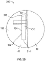
- Acoustic signal generators 210 are configured to provide or transmit an acoustic position signal to acoustic sensor 202 when hanger 150 enters a predetermined aligned position corresponding within wellhead 102. Particularly, in this embodiment, acoustic signal generators 210 are configured to transmit an acoustic position signal to acoustic sensor 202 in response to physical engagement between landing shoulder 162 of hanger 150 and landing shoulder 112 of wellhead 102. As shown particularly in Figure 2B , in this embodiment each acoustic signal generator 210 comprises a shear pin or member 212 received within an aperture 164 extending into hanger 150.
- shear pin 212 projects axially downwards (i.e., parallel with central axis 105) from landing shoulder 162 of hanger 150.
- Shear pin 212 of each acoustic signal generator 210 is positioned proximal a radially outer end of landing shoulder 162 such that shear pin 212 is disposed axially between landing shoulder 162 of hanger 150 of landing shoulder 112 of wellhead 102.
- figures 2A and 2B illustrate wellhead system 100 in a first or initial run-in position during the installation of wellhead component 150 within wellhead 102 via tool 24.
- landing shoulder 162 of hanger 150 is disposed distal landing shoulder 112 of wellhead 102.
- Tool 24 and string 22 axially convey hanger 150 downwards through the bore 104 towards the landing shoulder 112 of wellhead 102.
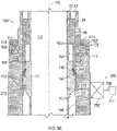
- Figures 3A and 3B illustrate hanger 150 once it has been conveyed to a position proximal to, but spaced from, landing shoulder 112 of wellhead 102.
- the terminal end 214 of the shear pin 212 of each acoustic signal generator 210 is disposed directly adjacent or contacts the landing shoulder 112 of wellhead 102.
- a small axial gap 216 extends between landing shoulder 162 of hanger 150 and the landing shoulder 112 of wellhead 102, where axial gap 216 corresponds to or comprises the axial projection of shear pin 212 from the landing shoulder 162 of hanger 150.
- the terminal end 214 of the shear pin 212 of each acoustic signal generator 210 has yet to shear, and thus, has not transmitted an acoustic position signal to the acoustic sensor 202 of position indication system 200.
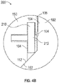
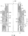
- Figures 4A and 4B illustrate hanger 150 in a third or predetermined aligned position corresponding to a fully landed position of hanger 150 within the bore 104 of wellhead 102.
- landing shoulder 162 of hanger 150 fully physically engages the landing shoulder 112 of wellhead 102, properly axially locating hanger 150 within bore 104 of wellhead 102.
- the terminal end 214 of the shear pin 212 of each acoustic signal generator 210 has been sheared off via physical engagement between shear pin 212 and the landing shoulder 112 of wellhead 102.
- shear pins 212 generates an acoustic position signal that is transmitted to and received by the acoustic sensor 202.
- shear pins 212 are configured to emit an acoustic position signal in response to the shearing of terminal end 214 that differs in acoustic frequency than the acoustic frequencies generated during normal operations of well system 10.
- acoustic sensor 202 is configured to filter the acoustic frequencies commonly generated during normal operations of well system 10 such that sensor 202 is configured to sense the unique or different frequency comprising the acoustic position signal emitted by shear pins 212 in response to the shearing of terminal ends 214.
- acoustic sensor 202 is configured to transmit a position signal to signal transmitter 204 corresponding to the received acoustic position signal when hanger 150 enters the predetermined aligned position in wellhead 102.
- signal transmitter 204 transmits the position signal to a location distal wellhead system 100, such as a surface vessel, where the position signal may be indicated to personnel of well system 10.
- the indication of the position signal provides a positive or direct indication of the proper landing of hanger 150 within the bore 104 of wellhead 102.
- the indication of the position signal provides a positive or direct indication of physical engagement between landing shoulder 162 of hanger 150 and the landing shoulder 112 of wellhead 102.
- position indication system 200 Having received the indication of proper landing of hanger 150 within wellhead 102, personnel of well system 10 may finish the installation of hanger 150 within wellhead 102, decouple tool 24 from hanger 150, and retract string 22 and tool 24 coupled thereto from wellhead system 100.
- a positive or direct indication of proper landing of hanger 150 within wellhead 102 may be provided via position indication system 200, obviating the need for a "dummy run” or other preliminary conveyance of hanger 150 (or other component installed in wellhead 102) into wellhead 102 in order to calibrate or indirectly determine the length of string 22 necessary to properly land hanger 150 within wellhead 102.
- the positive or direct positioning indication provided by position indication system 200 reduces the risk of improperly or incompletely landing hanger 150 within wellhead 102 (i.e., a "false positive" landing) of which indirect positioning systems and methods are susceptible.
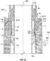
- wellhead system 300 has a central or longitudinal axis 305 that is disposed coaxial with the central axis 15 of well system 10 and generally includes a wellhead 302 and a wellhead component 320 comprising a tubing or casing hanger 320.
- wellhead system 300 is shown in Figure 5A as only including wellhead 302 and hanger 320, in other embodiments, wellhead system 300 may include additional components not shown in Figure 5A .
- Wellhead system 300 additionally includes a position indication system 350, as will be discussed further herein.
- Wellhead system 300 may comprise a component of well system 10 described above and shown in Figure 1 , or other well systems.
- Wellhead 302 and hanger 320 include features in common with wellhead 102 and hanger 150 of the wellhead system 100 described above, and shared features are labeled similarly.
- Wellhead 302 includes a bore 304 and a generally cylindrical inner surface 306 that extends axially from a first or upper end 302A of wellhead 302.
- Hanger 320 includes a bore 322 and a generally cylindrical outer surface 324 that extends axially from a first or upper end 320A of hanger 320.
- the inner surface 306 of wellhead 302 includes landing shoulder 112 and the outer surface 324 of hanger 320 includes landing shoulder 162.
- position indication system 350 generally includes an indicator member 352 disposed in the outer surface 324 of hanger 320 and an sensor 354 disposed in the inner surface 306 of wellhead 302.
- indicator member 352 comprises a magnetic member 352
- sensor 354 comprises an annular magnetic sensor 354.
- Magnetic sensor 354 is configured to sense a magnetic field produced by the magnetic member 352 and transmit a position signal to a signal transmitter 356 via a cable or data link 358 when magnetic member 352 is disposed directly adjacent or in close proximity with magnetic sensor 354.
- magnetic sensor 354 comprises a Hall effect sensor; however, in other embodiments, magnetic sensor 354 may comprise other sensors known in the art that are configured to respond to a magnetic field.
- indicator member 352 may comprise a visual indicator while sensor 354 comprises an optical sensor configured to sense the presence of indicator member 352 when indicator member 352 enters the field of view of the sensor 354.
- sensor 354 may comprise other proximity sensors known in the art configured to output a signal in response to the disposition of an indicator within close proximity of sensor 354.
- magnetic member 352 is positioned at an outer radial end 162O (shown in Figure 5B ) of the landing shoulder 162 of hanger 320 while magnetic sensor 354 is positioned at an outer radial end 112O (shown in Figure 5B ) of the landing shoulder 112 of wellhead 302.
- magnetic sensor 354 is configured to transmit the position signal to signal transmitter 356 in response to hanger 320 landing in wellhead 302 with landing shoulder 162 of hanger 320 in physical engagement or contacting landing shoulder 112 of wellhead 302.
- Signal transmitter 356 is configured similarly to signal transmitter 204 of position indication system 200 described above, and thus, is configured to transmit in real-time or near real-time the position signal provided by magnetic sensor 354 to a location remote wellhead system 300, such as a surface vessel disposed above wellhead system 300.
- a location remote wellhead system 300 such as a surface vessel disposed above wellhead system 300.
- magnetic sensor 354 is described as an annular sensor, in other embodiments, magnetic sensor 354 may comprise other shapes and geometries, including non-annular geometries.
- figures 5A and 5B illustrate wellhead component or hanger 320 of wellhead system 300 in a first position during the installation of wellhead component or hanger 320 within wellhead 302 via tool 24. In this position, landing shoulder 162 of hanger 320 is positioned proximal to, but axially spaced from, landing shoulder 112 of wellhead 302.
- an axial gap or misalignment 360 extends between magnetic member 352 of hanger 320 and the magnetic sensor 354 of wellhead 302 when hanger 320 is disposed in the first position shown in Figures 5A and 5B , where axial gap 360 corresponds to the axial gap or distance extending between landing shoulder 162 of hanger 320 and the landing shoulder 112 of wellhead 302.
- magnetic sensor 354 does not transmit the position signal to signal transmitter 356.
- Figures 6A and 6B illustrate hanger 320 in a second or predetermined aligned position corresponding to a fully landed position of hanger 320 within the bore 304 of wellhead 302.
- the magnetic member 352 In this position of hanger 320, the magnetic member 352 is axially aligned with magnetic sensor 354, as shown particularly in Figure 6B .
- magnetic sensor 354 in response to sensing the magnetic field produced by magnetic member 352 when magnetic member 352 is in axial alignment with sensor 354, transmits the position signal to signal transmitter 356 via cable 358.
- signal transmitter 356 transmits the position signal to a location distal wellhead system 300, such as a surface vessel, where the position signal may be indicated to personnel of well system 10.
- the indication of the position signal provides a positive or direct indication of the proper landing of hanger 320 within the bore 304 of wellhead 302.
- the indication of the position signal provides a positive or direct indication of physical engagement between landing shoulder 162 of hanger 320 and the landing shoulder 112 of wellhead 302, similar to the operation of signal transmitter 204 discussed above.
- magnetic sensor 354 may output a position signal that varies in power or voltage as magnetic member 352 approaches the axial alignment with magnetic sensor 354 shown in Figure 6B .
- signal transmitter 356 may be configured to only transmit the position signal upon receiving a threshold voltage from magnetic sensor 354 that corresponds with axial alignment between magnetic member 352 and magnetic sensor 354.
- wellhead system 400 has a central or longitudinal axis 405 that is disposed coaxial with central axis 15 of well system 10 and generally includes a wellhead 302 and a wellhead component 430 comprising a bowl or spool 430.
- wellhead system 400 is shown in Figure 7A as only including wellhead 402 and bowl 430, in other embodiments, wellhead system 400 may include additional components not shown in Figure 7A .
- Wellhead system 400 includes a position indication system 500, as will be discussed further herein.
- Wellhead system 400 may comprise a component of well system 10 described above and shown in Figure 1 , or other well systems.
- Wellhead 402 of wellhead system 400 includes a bore 404 and a generally cylindrical inner surface 406 that extends axially from a first or upper end 402A of wellhead 402.
- wellhead 402 comprises a "full bore” wellhead that does not include an internal landing shoulder, contra to wellheads 102 and 302 described above, each of which included landing shoulder 112.
- Full bore wellhead 402 provides greater inner diameter therein for more convenient access to wellbore 8.
- the inner surface 406 of wellhead 402 includes an annular locking groove 408 extending radially therein and positioned proximal upper end 402A.
- Bowl 430 of wellhead system 400 may be releasably coupled with wellhead 402 via locking groove 408 and is configured to provide a landing shoulder for additional components installed within wellhead 402, such as casing or tubing hangers.
- bowl 430 includes a bore 432 extending between a first or upper end 430A and a second or lower end 430B of bowl 430.
- Bowl 430 additionally includes a generally cylindrical outer surface 434 that extends between ends 430A and 430B and includes an annular, radially outwards extending shoulder 436 that is positioned proximal lower end 430B.
- bowl 430 includes a generally cylindrical inner surface 438 extending between ends 430A and 430B and including an annular landing shoulder 440 extending from upper end 430A.
- Landing shoulder 440 is configured to physically engage a corresponding landing shoulder of a wellhead component to be landed within wellhead 402.
- landing shoulder 440 of bowl 430 may be used to land hanger 150 or hanger 320 within wellhead 402 of wellhead system 400.
- Wellhead system 400 additionally includes an annular locking ring 450 and an annular engagement ring 470 releasably coupled with tool 24.
- Locking ring 450 is configured to releasably lock bowl 430 to wellhead 402 via physical engagement with the inner surface 406 of wellhead 402.
- locking ring 450 includes a radially inner or unlocked position (shown in Figure 7A ) where locking ring 450 is clear of locking groove 408 of wellhead 402, and a radially outer or locked position (not shown) where locking ring 450 is at least partially disposed within locking groove 408.
- Engagement ring 470 is configured to actuate locking ring 450 between unlocked and locked positions in response to actuation from tool 24, such as the application of a torque to engagement ring 470 from tool 24.
- engagement ring 470 is coupled with bowl 430 via a connecting member 480 extending radially therebetween.
- an upper end of locking ring 450 includes an engagement shoulder 452 while a lower end of engagement ring 470 includes a corresponding engagement shoulder 472.
- Position indication system 500 of wellhead system 400 is configured to provide an indication when bowl 430 and locking ring 450 are axially aligned with locking groove 408 of wellhead 402.
- position indication system 500 generally includes an indicator member 502 and a sensor 504.
- indicator member 502 is positioned on an outer surface 474 of engagement member 470 and comprises a magnetic member 502 similar in configuration to magnetic member 352 of position indication system 350.
- magnetic member 502 may be positioned on an outer surface 454 of locking ring 450 or the outer surface 343 of bowl 430.
- magnetic member 502 may comprise another form of indicator member, such as a visual indicator.
- sensor 504 is positioned on the inner surface 406 of wellhead 402 and comprises a magnetic sensor 504 similar in configuration to magnetic sensor 354 of position indication system 350.
- sensor 504 may comprise other proximity sensors known in the art, including optical sensors for detecting a visual indicator.
- indicator member 502 could comprise a shear pin configured to emit an acoustic positioning signal when locking ring 450 achieves axial alignment with locking groove 408 of wellhead 402, which could be received by sensor 504 with sensor 504 comprising an acoustic sensor.
- position indication system 500 additionally comprises signal transmitter 506 and cable or data link 508, which are similar in configuration to signal transmitter 356 and cable 358 of position indication system 350 described above.
- figures 7A and 7B illustrate wellhead component or bowl 430 of wellhead system 400 in a first position during the installation of wellhead component or bowl 430 within wellhead 402 via tool 24.
- locking ring 450 is positioned proximal to, but axially spaced from, an axially aligned position with locking groove 408 of wellhead 402.
- an axial gap or misalignment 510 extends between magnetic member 502 of bowl 430 and the magnetic sensor 504 of wellhead 402 when bowl 430 is disposed in the first position shown in Figures 7A and 7B , where axial gap 510 corresponds to the axial gap or distance extending between the position of locking ring 450 when bowl 430 is disposed in the first position and the axial position of locking ring 450 when locking ring 450 is axially aligned with locking groove 408 of wellhead 402.
- magnetic sensor 504 does not transmit the position signal to signal transmitter 506.
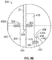
- FIGs 8A and 8B illustrate bowl 430 in a second or predetermined aligned position corresponding to an axial position of locking ring 450 where locking 450 is axially aligned with locking groove 408 of wellhead 402.
- magnetic member 502 In the second position of bowl 430, magnetic member 502 is axially aligned with magnetic sensor 504, as shown particularly in Figure 8B .
- magnetic sensor 504 in response to sensing the magnetic field produced by magnetic member 502 when magnetic member 502 is in axial alignment with magnetic sensor 504, transmits the position signal to signal transmitter 506 via cable 508.
- signal transmitter 506 transmits the position signal to a location distal wellhead system 400, such as a surface vessel, where the position signal may be indicated to personnel of well system 10.
- the indication of the position signal provides a positive or direct indication of axial alignment between locking ring 450 and locking groove 408 of wellhead 402.
- magnetic sensor 504 may output a position signal that varies in power or voltage as magnetic member 502 approaches the axial alignment with magnetic member 504 shown in Figure 8B .
- signal transmitter 506 may be configured to only transmit the position signal upon receiving a threshold voltage from magnetic sensor 504 that corresponds with axial alignment between magnetic member 502 and magnetic sensor 504. Following the transmission of the position signal to a position distal wellhead system 400, such as a surface vessel, the engagement ring 470 may be actuated by tool 24 to actuate locking ring 450 into the locked position to lock bowl 430 to wellhead 402.
- wellhead system 600 has a central or longitudinal axis 605 that is disposed coaxial with central axis 15 of well system 10 and generally includes a wellhead 602.
- wellhead system 600 may include additional wellhead components, such as casing or tubing hangers and/or bowls.
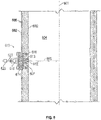
- wellhead 602 includes a bore 604 defined by a generally cylindrical inner surface 606.
- Wellhead 602 additionally includes a generally cylindrical outer surface 608.
- Wellhead 602 further includes a wellbore monitoring assembly 610 configured to provide for nonintrusive monitoring of conditions, such as pressure, temperature, fluid composition, position of wellhead components, etc., within wellbore 8 and bore 604 of wellhead 602.
- wellbore monitoring assembly 610 has a central or longitudinal axis 615 that is disposed orthogonal central axis 605 of wellhead system 600 and includes a pressure window 612 disposed in a receptacle 607 of wellhead 602 and extending between outer surface 608 and inner surface 606 of wellhead 602.
- Wellbore monitoring assembly 610 also includes a sensor housing 614 mounted to the outer surface 608 of wellhead 602 and including a sensor package 616 disposed therein (shown schematically in Figure 9 ).
- Pressure window 612 is configured to provide access to bore 604 of wellhead 602 while sealing bore 604 from the surrounding environment. Specifically, pressure window 612 allows sensor(s) of sensor package 616 to actively and non-intrusively monitor conditions within wellbore 8 and bore 604 of wellhead 602.
- sensor package 616 comprises a pressure sensor and a temperature sensor, where pressure window 612 allows the pressure and temperature sensors of sensor package 616 to actively monitor and measure pressure and temperature within wellbore 8 and bore 604 of wellhead 602.
- sensor package 616 comprises a pressure sensor and a temperature sensor
- sensor package 616 may comprise a single sensor or multiple sensors including sensors configured to measure other parameters beyond pressure and temperature, such as fluid composition or the physical position (e.g., a magnetic sensor and/or an optical sensor) of components disposed in bore 604 of wellhead 602.
- pressure window 612 comprises a sapphire glass material sealed to the material comprising wellhead 602, such as sapphire glass produced by Rayotek Scientific Inc.
- pressure window 612 may comprise other materials configured to provide non-intrusive sensor access to bore 604 of wellhead 602 while sealing bore 604 from the surrounding environment.
- a seal or gasket 618 is disposed between sensor housing 614 and the outer surface 608 of wellhead 602 to provide a dual-barrier sealing arrangement between the bore 604 of wellhead 602 and the surrounding environment.
- a sealing interface 613 formed between pressure window 612 and the receptacle 607 of wellhead 602 comprises a primary seal while seal 618 forms a secondary seal between bore 604 and the surrounding environment.
- the material comprising pressure window 612 e.g., sapphire glass, etc.
- wellbore monitoring assembly 610 further comprises a signal transmitter 620 in signal communication with sensor package 616 of sensor housing 614 via a cable or data link 622 extending therebetween.
- Signal transmitter 620 is configured provide real-time or near real-time transmission of sensor signals (e.g., signals corresponding to pressure measurements, temperature measurements, etc.) outputted by sensor package 616 to signal transmitter 620.
- signal transmitter 620 comprises a wireless transmitter configured to transmit a wireless data signal to a signal receiver, such as a receiver disposed on a surface vessel above wellhead system 600 at the waterline.
- signal transmitter 620 comprises a hardwired connection between the sensor package 616 and the signal receiver.
- transmitter 620 may comprise a hardwired connection routed along a marine riser extending between wellhead 602 and a surface vessel. In this manner, conditions within wellbore 8 and bore 604 of wellhead 602 may be monitored in real-time.
- sensor package 616 may be used to assist in positioning components within wellhead 602 via real-time optical or visual monitoring of bore 604.
- wellbore monitoring assembly 610 may not include signal transmitter 620, and instead, may comprise a data storage and processing unit configured to store data provided by sensor package 616 for later retrieval.
- a wellhead component e.g., wellhead component 150 of wellhead system 100
- a wellhead e.g., wellhead 102 of wellhead system 100
- the wellhead component is disposed in a predetermined aligned position (e.g., the position of wellhead component 150 shown in Figures 4A and 4B ) in the bore of the wellhead.
- a position signal is transmitted from a position sensor (e.g., position or acoustic sensor 202 of position indication system 200) in response to disposing the wellhead component in the predetermined aligned position.
- the position signal is transmitted in response to physically engaging a landing shoulder of the wellhead component (e.g., landing shoulder 162 of wellhead component 150) with a landing shoulder of a wellhead (e.g., landing shoulder 112 of wellhead 102).
- the position signal is transmitted in response to aligning a locking ring (e.g., locking ring 450 of wellhead system 400) with a locking groove (e.g., locking groove 408 of wellhead 402 of wellhead system 400) disposed in an inner surface of the wellhead (e.g., wellhead 402).
- the position signal is transmitted in response to an acoustic signal generator (e.g., acoustic signal generator 210 of position 200) coupled to the wellhead component generating an acoustic position signal.
- the position signal is transmitted in response to aligning a magnetic member (e.g., magnetic member 352 of position indication system 350) of the wellhead component with the position sensor (e.g., position or magnetic sensor 354 of position indication system 350).
Landscapes
- Geology (AREA)
- Life Sciences & Earth Sciences (AREA)
- Engineering & Computer Science (AREA)
- Mining & Mineral Resources (AREA)
- Physics & Mathematics (AREA)
- Environmental & Geological Engineering (AREA)
- Fluid Mechanics (AREA)
- General Life Sciences & Earth Sciences (AREA)
- Geochemistry & Mineralogy (AREA)
- Geophysics (AREA)
- Acoustics & Sound (AREA)
- Geophysics And Detection Of Objects (AREA)
- Excavating Of Shafts Or Tunnels (AREA)
Description
- The present application claims benefit of
U.S. provisional patent application No. 62/432,808 filed December 12, 2016 - Hydrocarbon drilling and production systems require various components to access and extract hydrocarbons from subterranean earthen formations. Such systems generally include a wellhead assembly through which the hydrocarbons, such as oil and natural gas, are extracted. The wellhead assembly may include a variety of components, such as valves, fluid conduits, controls, casings, hangers, and the like to control drilling and/or extraction operations. In some operations, hangers, such as tubing or casing hangers, may be used to suspend strings (e.g., piping for various fluid flows into and out of the well) in the well. Such hangers may be disposed or received in a housing, spool, or bowl. In addition to suspending strings inside the wellhead assembly, the hangers provide sealing to seal the interior of the wellhead assembly and strings from pressure inside the wellhead assembly.
- In some applications, an initial or calibrating run (i.e., a "dummy run") of equipment into the wellhead must be made where a mark is placed on a landing joint corresponding to the landing position of the equipment run into the wellhead. Subsequently, the wellhead is rerun into the wellhead and the mark made on the landing joint is used to determine if the equipment is properly landed within the wellhead. Besides requiring two separate operations of running the equipment into the wellhead, because the landing of the equipment within the wellhead may only be determined indirectly, via the use of the mark made on the landing joint, such a landing operation provides no means for verifying if the equipment is properly landed within the wellhead, creating a risk of improperly landing or misaligning the equipment that is landed and installed within the wellhead.
-
US2007/0039738 shows a wellhead with a set of circumferential grooves in an internal surface. A tubing hanger to be inserted in the wellhead carries suspension dogs which can be pushed outwards to engage the grooves and hold the tubing hanger in place. An axial position transmitter on a running tool is detected by a receiver on a riser above the well head. Also, an electrical circuit supplied by a controller at the surface is completed when a conductor carried by the tubing attached to the tubing hanger comes into contact with the wellhead and casing extending down from the wellhead.US 2016/0090802 shows a tool carrying a light source which indicates position when the light shines through an aperture in a wellhead component.US2011/02533889 - A wellhead system comprises a wellhead with a landing shoulder therein and a wellhead component to be installed in the wellhead at a predetermined aligned position in the wellhead, the wellhead component comprising a position indicator disposed in an outer surface of the wellhead component, and the wellhead comprising a position sensor configured to transmit a position signal in response to the position indicator contacting the landing shoulder of the wellhead as the wellhead component enters into a predetermined aligned position in the wellhead. In some embodiments, the wellhead component comprises a tubing or casing hanger. In some embodiments, the predetermined aligned position of the tubing or casing hanger comprises a position where a landing shoulder of the tubing or casing hanger physically engages a landing shoulder of the wellhead. In certain embodiments, the wellhead component comprises a bowl and a locking ring configured to releasably couple the bowl to the wellhead, wherein the bowl comprises a landing shoulder. In certain embodiments, the predetermined aligned position of the bowl comprises a position where the locking ring is aligned with a locking groove disposed in the inner surface of the wellhead. In some embodiments, the position indicator comprises a magnetic member and the position sensor comprises a magnetic sensor. In some embodiments, the position indicator comprises an acoustic signal generator and the position sensor comprises an acoustic sensor. In certain embodiments, the acoustic signal generator comprises a shear pin configured to a shear a terminal end thereof in response to the wellhead component entering into the predetermined aligned position. In certain embodiments, the wellhead system further comprises a signal transmitter in signal communication with the position sensor, wherein the signal transmitter is configured to transmit the position signal in real-time from the position sensor to a location distal the wellhead system.
- An embodiment of a wellhead system comprises a wellhead comprising a bore, and a wellbore monitoring assembly coupled to the wellhead, wherein the wellbore monitoring assembly comprises a sensor package disposed in a sensor housing, and a window disposed in a receptacle of the wellhead. In some embodiments, the sensor package is configured to monitor conditions in the bore of the wellhead via the window disposed in the wellhead. In some embodiments, the window comprises a sapphire glass material. In certain embodiments, the wellhead system further comprises a sealing interface disposed between the window and the receptacle of the wellhead, wherein the sealing interface comprises a primary seal between the bore of the wellhead and the surrounding environment, a gasket disposed between the sensor housing and an outer surface of the wellhead, wherein the gasket comprises a secondary seal between the bore of the wellhead and the surrounding environment. In certain embodiments, the sensor package comprises a temperature sensor and a pressure sensor. In some embodiments, the wellhead system further comprises a signal transmitter in signal communication with the sensor package, wherein the signal transmitter is configured to transmit a sensor signal from the sensor package in real-time to a location distal the wellhead system.
- A method of landing a wellhead component in a wellhead with a landing shoulder therein, wherein the wellhead component comprises a position indicator, comprises disposing the wellhead component in a bore of the wellhead, disposing the wellhead component in a predetermined aligned position in the bore of the wellhead, wherein the position indicator is disposed in an outer surface of the wellhead component and contacts the landing shoulder of the wellhead as the wellhead component enters into the predetermined aligned position in the wellhead, the wellhead comprises a position sensor and the method comprises transmitting a position signal from a position sensor in response to the position indicator contacting the landing shoulder of the wellhead on disposing the wellhead component in the predetermined aligned position. In some embodiments, the method further comprises transmitting the position signal in response to physically engaging a landing shoulder of the wellhead component with a landing shoulder of the wellhead. In some embodiments, the method further comprises transmitting the position signal in response to aligning a locking ring with a locking groove disposed in an inner surface of the wellhead. In certain embodiments, the method further comprises transmitting the position signal in response to an acoustic signal generator coupled to the wellhead component generating an acoustic position signal. In certain embodiments, the method further comprises transmitting the position signal in response to aligning a magnetic member of the wellhead component with the position sensor.
- For a detailed description of exemplary embodiments, reference will now be made to the accompanying drawings in which:
-
Figure 1 is a schematic view of an embodiment of a well system in accordance with principles disclosed herein; -
Figure 2A is a schematic cross-sectional view of an embodiment of a wellhead system of the well system ofFigure 1 , shown in a first position, in accordance with principles disclosed herein, -
Figure 2B is a zoomed-in, schematic view of an embodiment of a shear member of the wellhead system ofFigure 2A , shown in a first position, in accordance with principles disclosed herein; -
Figure 3A is a schematic cross-sectional view of the wellhead system ofFigure 2A shown in a second position; -
Figure 3B is a zoomed-in schematic view of the shear member ofFigure 2B shown in a second position; -
Figure 4A is a schematic cross-sectional view of the wellhead system ofFigure 2A shown in a third position; -
Figure 4B is a zoomed-in schematic view of the shear member ofFigure 2B shown in a third position; -
Figure 5A is a schematic cross-sectional view of another embodiment of a wellhead system of the well system ofFigure 1 , shown in a first position, in accordance with principles disclosed herein, -
Figure 5B is a zoomed-in, schematic view of an embodiment of a position indication system of the wellhead system ofFigure 5A , shown in a first position, in accordance with principles disclosed herein; -
Figure 6A is a schematic cross-sectional view of the wellhead system ofFigure 5A shown in a second position; -
Figure 6B is a zoomed-in schematic view of the position indication system ofFigure 5B shown in a second position; -
Figure 7A is a schematic cross-sectional view of another embodiment of a wellhead system of the well system ofFigure 1 , shown in a first position, in accordance with principles disclosed herein, -
Figure 7B is a zoomed-in, schematic view of an embodiment of a position indication system of the wellhead system ofFigure 5A , shown in a first position, in accordance with principles disclosed herein; -
Figure 8A is a schematic cross-sectional view of the wellhead system ofFigure 5A shown in a second position; -
Figure 8B is a zoomed-in schematic view of the position indication system ofFigure 5B shown in a second position; -
Figure 9 is a schematic cross-sectional view of another embodiment of a wellhead system of the well system ofFigure 1 in accordance with principles disclosed herein; and -
Figure 10 is a flowchart of an embodiment of a method of landing a wellhead component in a wellhead is shown in accordance with principles disclosed herein. - In the drawings and description that follow, like parts are typically marked throughout the specification and drawings with the same reference numerals. The drawing figures are not necessarily to scale. Certain features of the disclosed embodiments may be shown exaggerated in scale or in somewhat schematic form and some details of conventional elements may not be shown in the interest of clarity and conciseness. The present disclosure is susceptible to embodiments of different forms. Specific embodiments are described in detail and are shown in the drawings, with the understanding that the present disclosure is to be considered an exemplification of the principles of the disclosure, and is not intended to limit the disclosure to that illustrated and described herein. It is to be fully recognized that the different teachings of the embodiments discussed below may be employed separately or in any suitable combination to produce desired results.
- Unless otherwise specified, in the following discussion and in the claims, the terms "including" and "comprising" are used in an open-ended fashion, and thus should be interpreted to mean "including, but not limited to ... ". Any use of any form of the terms "connect", "engage", "couple", "attach", or any other term describing an interaction between elements is not meant to limit the interaction to direct interaction between the elements and may also include indirect interaction between the elements described. The various characteristics mentioned above, as well as other features and characteristics described in more detail below, will be readily apparent to those skilled in the art upon reading the following detailed description of the embodiments, and by referring to the accompanying drawings.
-
Figure 1 is a schematic diagram showing an embodiment of awell system 10 having a central orlongitudinal axis 15. Thewell system 10 can be configured to extract various minerals and natural resources, including hydrocarbons (e.g., oil and/or natural gas), or configured to inject substances into an earthen surface 4 and an earthen formation 6 via a well or wellbore 8. In some embodiments, thewell system 10 is land-based, such that the surface 4 is land surface, or subsea, such that the surface 4 is the seal floor. Thesystem 10 includes awellhead system 100 including awellhead 102 that can receive a tool ortubular string conveyance 20. Thewellhead 102 ofwellhead system 100 is coupled to a wellbore 8 via a wellhead connector orhub 30.Wellhead 102 typically includes multiple components that control and regulate activities and conditions associated with the wellbore 8. For example, thewellhead 102 generally includes bodies, valves and seals that route produced fluids from the wellbore 8, provide for regulating pressure in the wellbore 8, and provide for the injection of substances or chemicals downhole into the wellbore 8. Although in the embodiment shown inFigure 1 wellhead system 100 forms a part ofwell system 10, in other embodiments,wellhead system 100 may be used in other well systems. - In the embodiment shown in
Figure 1 , wellsystem 10 includes a Christmas tree ortree 40 coupled to thewellhead 102 ofwellhead system 100 and a blowout preventer (BOP) stack 50 coupled to thetree 40.BOP stack 50 may include a variety of valves, fittings, and controls to prevent oil, gas, or other fluid from exiting the wellbore 8 in the event of an unintentional release of pressure or an overpressure condition. Additionally, in thisembodiment wellhead system 100 includes awellhead component 150 that is disposed within thewellhead 102 ofwellhead system 100. In this embodiment,wellhead component 150 comprises a tubing and/or casing spool or housing. For ease of description below, reference to "tubing" shall include casing and other tubulars associated with wellheads. Further, "spool" may also be referred to as "housing," "receptacle," or "bowl." - The
system 10 may include other devices that are coupled to thewellhead 102 ofwellhead system 100, and devices that are used to assemble and control various components of thewellhead 102. For example, in the illustrated embodiment, wellsystem 10 includestool conveyance 20 including atool 24 suspended from a tool orstring 22. In certain embodiments,tool 24 comprises a running tool that is lowered (e.g., run) from an offshore vessel (not shown) to the wellbore 8 and/or thewellhead 102. In this embodiment,string 22 may comprise a drill string lowered from the offshore vessel. In other embodiments, such as land surface systems,tool 24 may include a device suspended over and/or lowered into thewellhead 102 via a crane or other supporting device. - The
tree 40 generally includes a variety of flow paths, bores, valves, fittings, and controls for operating the wellbore 8. Thetree 40 may provide fluid communication with the wellbore 8. For example, thetree 40 includes atree bore 42. The tree bore 42 provides for completion and workover procedures, such as the insertion of tools into the wellbore 8, the injection of various substances into the wellbore 8, and the like. Further, fluids extracted from the wellbore 8, such as oil and natural gas, may be regulated and routed via thetree 40. As is shown in thesystem 10, the tree bore 42 may fluidly couple and communicate with a BOP bore 52 of theBOP stack 50. - In the embodiment shown in
Figure 1 ,wellhead 102 ofwellhead system 100 provides a base for thetree 40 andBOP stack 50. In this embodiment,wellhead component 150 includes a wellhead component bore 152 that fluidly couples with and enables fluid communication between the tree bore 42 and the wellbore 8. Thus, bores 52, 42, and 152 provide access to the wellbore 8 for various completion and workover procedures. For example, components can be run down to thewellhead 102 and disposed in the wellhead component bore 152 to seal off the wellbore 8, to inject fluids downhole, to suspend tools downhole, to retrieve tools downhole, and the like. For instance, additional casing and/or tubing hangers may be installed withinwellhead component 150 via the access provided bybores wellhead component 150 is conveyed to thewellhead 102 viatool conveyance 20 for installation within awellhead bore 104 ofwellhead 102. Similarly, additional casing and/or tubing hangers may be conveyed to thewellhead 102 viatool conveyance 20 for installation withinbore 152 ofwellhead component 150. In certain embodiments, associated components of the casing and/or tubing hangers, such as seal or packoff assemblies, are installed within either wellhead bore 104 ofwellhead 102 and/or wellhead component bore 152 ofwellhead component 150 viatool 24 ofconveyance tool 20. As will be described further herein, in some embodiments thetool 24 is configured to installwellhead component 150 and accessary components thereof withinwellhead 102. - As one of ordinary skill in the art understands, the wellbore 8 may contain elevated pressures. For example, the wellbore 8 may include pressures that exceed 69MPa (10,000 pounds per square inch (PSI)). Accordingly, well
system 10 employs various mechanisms, such as mandrels, seals, plugs and valves, to control and regulate the wellbore 8. For example, thewellhead component 150 may be disposed within thewellhead 102 to secure tubing and casing suspended in the wellbore 8, and to provide a path for hydraulic control fluid, chemical injections, and the like. In this embodiment, wellhead component bore 152 ofwellhead component 150 is in fluid communication with the wellbore 8. - Referring to
Figures 2A and2B , in the embodiment shownwellhead system 100 includes a central orlongitudinal axis 105 that is disposed coaxial with thecentral axis 15 ofwell system 10. Althoughwellhead system 100 is shown inFigure 2A as only includingwellhead 102 andhanger 150, in other embodiments,wellhead system 100 may include additional components not shown inFigure 2A .Wellhead 102 includes a first orupper end 102A and a generally cylindricalinner surface 106 extending fromupper end 102A, whereinner surface 106 defines bore 104 ofwellhead 102.Wellhead 102 is coupled totree 40 via a plurality of radially actuatable locking members ordogs 108 disposed in theinner surface 106 ofwellhead 102. Particularly, eachdog 108 is radially actuatable via acorresponding pin 110 between a radially outer position out of engagement withtree 40, and a radially inner position where eachdog 108 engages a groove disposed in an outer surface oftree 40. Although in thisembodiment wellhead 102 is coupled withtree 40, in other embodiments,wellhead 102 may be directly coupled withBOP stack 50. In such embodiments, wellsystem 10 may includetree 40. Theinner surface 106 ofwellhead 102 additionally includes an annular landing orengagement shoulder 112 extending radially inwards intobore 104. Landingshoulder 112 is configured to receive and physically engagewellhead component 150, as will be described further herein. Further,inner surface 106 includes a plurality of axially spacedannular seal assemblies 114 disposed therein and configured to sealingly engage an outer surface oftree 40 to isolate or seal bore 104 ofwellhead 102 from the surrounding environment. - In the embodiment shown in
Figures 2A and2B ,wellhead component 150 comprises a tubing orcasing hanger 150 including a first orupper end 150A and a generally cylindricalouter surface 154 extending axially fromupper end 150A.Outer surface 154 includes a pair of axially spacedseal assemblies 156 for sealingly engaging theinner surface 106 ofwellhead 102 oncehanger 150 has been installed withinwellhead 102.Outer surface 154 ofhanger 150 additionally includes anannular groove 158 that receives an annular locking member orring 160 that is configured to releasablycouple hanger 150 with alower end 24A oftool 24. In this arrangement,hanger 150 may be displaced from a surface vessel disposed at a waterline to thewellhead 102 viatool 24, installed withinwellhead 102, and released fromtool 24 to allowtool 24 to be retracted to the surface vessel viastring 22. - The
outer surface 154 ofhanger 150 includes an annular landing orengagement shoulder 162 configured to matingly engage with thelanding shoulder 112 ofwellhead 102. Specifically, physical engagement or contact between landingshoulder 162 ofhanger 150 and landingshoulder 112 ofwellhead 102 axially locateshanger 150 withinwellhead 102. Thus, in some embodiments, once landingshoulder 162 ofhanger 150 engages landingshoulder 112 ofwellhead 102,hanger 150 may be installed within or locked towellhead 102 andtool 24 may be disconnected fromhanger 150 and retracted fromwellhead system 100. -
Wellhead system 100 additionally includes aposition indication system 200 that is configured to provide a positive indication of proper axial location ofhanger 150 withinwellhead 102. In other words,position indication system 200 is configured to provide a signal or indication of the proper landing ofhanger 150 withinwellhead 102 or full physical engagement betweenlanding shoulder 162 ofhanger 150 and thelanding shoulder 112 ofwellhead 102. In the embodiment shown inFigure 2A and2B ,position indication system 200 generally includes aposition sensor 202 comprising anacoustic sensor 202 coupled to an outer surface 116 ofwellhead 102, whereacoustic sensor 202 is in signal communication with asignal transmitter 204 via a cable ordata link 206.Signal transmitter 204 is configured to provide real-time or near real-time transmission of data provided byacoustic sensor 202 to a locationdistal wellhead system 100. In some embodiments,signal transmitter 204 comprises a wireless transmitter configured to transmit a wireless data signal to a signal receiver, such as a receiver disposed on a surface vessel abovewellhead system 100 at the waterline. In other embodiments,signal transmitter 204 comprises a hardwired connection between theacoustic sensor 202 and the signal receiver. For instance, in someembodiments transmitter 204 may comprise a hardwired connection routed along a marine riser extending betweenwellhead 102 and a surface vessel. - In this embodiment,
position indication system 200 additionally comprises a plurality of circumferentially spaced acoustic signal generators orposition indicators 210 coupled tohanger 150. Although in this embodimentposition indication system 200 includes a plurality ofacoustic signal generators 210, in other embodiments,position indication system 200 may only include a singleacoustic signal generator 210. Further, although in this embodimentacoustic sensor 202 andsignal transmitter 204 are coupled towellhead 102 whileacoustic signal generators 210 are coupled tohanger 150, in other embodiments, signalgenerators 210 may be coupled towellhead 102 at or near landingshoulder 112 whileacoustic sensor 202 andsignal transmitter 204 are coupled tohanger 150. -
Acoustic signal generators 210 are configured to provide or transmit an acoustic position signal toacoustic sensor 202 whenhanger 150 enters a predetermined aligned position corresponding withinwellhead 102. Particularly, in this embodiment,acoustic signal generators 210 are configured to transmit an acoustic position signal toacoustic sensor 202 in response to physical engagement betweenlanding shoulder 162 ofhanger 150 and landingshoulder 112 ofwellhead 102. As shown particularly inFigure 2B , in this embodiment eachacoustic signal generator 210 comprises a shear pin ormember 212 received within anaperture 164 extending intohanger 150. In this configuration, an outerterminal end 214 ofshear pin 212 projects axially downwards (i.e., parallel with central axis 105) from landingshoulder 162 ofhanger 150.Shear pin 212 of eachacoustic signal generator 210 is positioned proximal a radially outer end of landingshoulder 162 such thatshear pin 212 is disposed axially between landingshoulder 162 ofhanger 150 of landingshoulder 112 ofwellhead 102. - Referring to
Figures 2A-4B ,figures 2A and2B illustratewellhead system 100 in a first or initial run-in position during the installation ofwellhead component 150 withinwellhead 102 viatool 24. In this position, landingshoulder 162 ofhanger 150 is disposeddistal landing shoulder 112 ofwellhead 102.Tool 24 andstring 22 axially conveyhanger 150 downwards through thebore 104 towards the landingshoulder 112 ofwellhead 102.Figures 3A and3B illustratehanger 150 once it has been conveyed to a position proximal to, but spaced from, landingshoulder 112 ofwellhead 102. Particularly, in this second position ofhanger 150, theterminal end 214 of theshear pin 212 of eachacoustic signal generator 210 is disposed directly adjacent or contacts thelanding shoulder 112 ofwellhead 102. In the second position ofhanger 150, a smallaxial gap 216 extends between landingshoulder 162 ofhanger 150 and thelanding shoulder 112 ofwellhead 102, whereaxial gap 216 corresponds to or comprises the axial projection ofshear pin 212 from thelanding shoulder 162 ofhanger 150. In this position, theterminal end 214 of theshear pin 212 of eachacoustic signal generator 210 has yet to shear, and thus, has not transmitted an acoustic position signal to theacoustic sensor 202 ofposition indication system 200. -
Figures 4A and4B illustratehanger 150 in a third or predetermined aligned position corresponding to a fully landed position ofhanger 150 within thebore 104 ofwellhead 102. In the third position ofhanger 150, landingshoulder 162 ofhanger 150 fully physically engages thelanding shoulder 112 ofwellhead 102, properly axially locatinghanger 150 withinbore 104 ofwellhead 102. In the third position, theterminal end 214 of theshear pin 212 of eachacoustic signal generator 210 has been sheared off via physical engagement betweenshear pin 212 and thelanding shoulder 112 ofwellhead 102. The shearing of theterminal end 214 of shear pins 212 generates an acoustic position signal that is transmitted to and received by theacoustic sensor 202. In this embodiment, shear pins 212 are configured to emit an acoustic position signal in response to the shearing ofterminal end 214 that differs in acoustic frequency than the acoustic frequencies generated during normal operations ofwell system 10. Additionally, in this embodiment,acoustic sensor 202 is configured to filter the acoustic frequencies commonly generated during normal operations ofwell system 10 such thatsensor 202 is configured to sense the unique or different frequency comprising the acoustic position signal emitted byshear pins 212 in response to the shearing of terminal ends 214. - When the acoustic position signal is transmitted from
acoustic signal generators 210 in response to the shearing of theterminal end 214 of eachshear pin 212, the acoustic position signal is received or sensed by theacoustic sensor 202. In this embodiment,acoustic sensor 202 is configured to transmit a position signal to signaltransmitter 204 corresponding to the received acoustic position signal whenhanger 150 enters the predetermined aligned position inwellhead 102. In response to receiving the position signal fromacoustic sensor 202,signal transmitter 204 transmits the position signal to a locationdistal wellhead system 100, such as a surface vessel, where the position signal may be indicated to personnel ofwell system 10. The indication of the position signal provides a positive or direct indication of the proper landing ofhanger 150 within thebore 104 ofwellhead 102. For instance, in some embodiments, the indication of the position signal provides a positive or direct indication of physical engagement betweenlanding shoulder 162 ofhanger 150 and thelanding shoulder 112 ofwellhead 102. - Having received the indication of proper landing of
hanger 150 withinwellhead 102, personnel ofwell system 10 may finish the installation ofhanger 150 withinwellhead 102, decoupletool 24 fromhanger 150, and retractstring 22 andtool 24 coupled thereto fromwellhead system 100. In this manner, a positive or direct indication of proper landing ofhanger 150 withinwellhead 102 may be provided viaposition indication system 200, obviating the need for a "dummy run" or other preliminary conveyance of hanger 150 (or other component installed in wellhead 102) intowellhead 102 in order to calibrate or indirectly determine the length ofstring 22 necessary to properly landhanger 150 withinwellhead 102. Additionally, the positive or direct positioning indication provided byposition indication system 200 reduces the risk of improperly or incompletely landinghanger 150 within wellhead 102 (i.e., a "false positive" landing) of which indirect positioning systems and methods are susceptible. - Referring to
Figures 5A and5B , another embodiment of awellhead system 300 is shown. In this embodiment,wellhead system 300 has a central orlongitudinal axis 305 that is disposed coaxial with thecentral axis 15 ofwell system 10 and generally includes awellhead 302 and awellhead component 320 comprising a tubing orcasing hanger 320. Althoughwellhead system 300 is shown inFigure 5A as only includingwellhead 302 andhanger 320, in other embodiments,wellhead system 300 may include additional components not shown inFigure 5A .Wellhead system 300 additionally includes aposition indication system 350, as will be discussed further herein.Wellhead system 300 may comprise a component ofwell system 10 described above and shown inFigure 1 , or other well systems.Wellhead 302 andhanger 320 include features in common withwellhead 102 andhanger 150 of thewellhead system 100 described above, and shared features are labeled similarly.Wellhead 302 includes abore 304 and a generally cylindricalinner surface 306 that extends axially from a first orupper end 302A ofwellhead 302.Hanger 320 includes a bore 322 and a generally cylindricalouter surface 324 that extends axially from a first orupper end 320A ofhanger 320. In this embodiment, theinner surface 306 ofwellhead 302 includes landingshoulder 112 and theouter surface 324 ofhanger 320 includes landingshoulder 162. - In the embodiment shown in
Figures 5A and5B ,position indication system 350 generally includes anindicator member 352 disposed in theouter surface 324 ofhanger 320 and ansensor 354 disposed in theinner surface 306 ofwellhead 302. In this embodiment,indicator member 352 comprises amagnetic member 352 andsensor 354 comprises an annularmagnetic sensor 354.Magnetic sensor 354 is configured to sense a magnetic field produced by themagnetic member 352 and transmit a position signal to asignal transmitter 356 via a cable ordata link 358 whenmagnetic member 352 is disposed directly adjacent or in close proximity withmagnetic sensor 354. In this embodiment,magnetic sensor 354 comprises a Hall effect sensor; however, in other embodiments,magnetic sensor 354 may comprise other sensors known in the art that are configured to respond to a magnetic field. In other embodiments,indicator member 352 may comprise a visual indicator whilesensor 354 comprises an optical sensor configured to sense the presence ofindicator member 352 whenindicator member 352 enters the field of view of thesensor 354. In still further embodiments,sensor 354 may comprise other proximity sensors known in the art configured to output a signal in response to the disposition of an indicator within close proximity ofsensor 354. - In the embodiment shown,
magnetic member 352 is positioned at an outer radial end 162O (shown inFigure 5B ) of thelanding shoulder 162 ofhanger 320 whilemagnetic sensor 354 is positioned at an outer radial end 112O (shown inFigure 5B ) of thelanding shoulder 112 ofwellhead 302. In this arrangement,magnetic sensor 354 is configured to transmit the position signal to signaltransmitter 356 in response tohanger 320 landing inwellhead 302 with landingshoulder 162 ofhanger 320 in physical engagement or contactinglanding shoulder 112 ofwellhead 302.Signal transmitter 356 is configured similarly to signaltransmitter 204 ofposition indication system 200 described above, and thus, is configured to transmit in real-time or near real-time the position signal provided bymagnetic sensor 354 to a locationremote wellhead system 300, such as a surface vessel disposed abovewellhead system 300. Although in this embodimentmagnetic sensor 354 is described as an annular sensor, in other embodiments,magnetic sensor 354 may comprise other shapes and geometries, including non-annular geometries. - Referring to
Figures 5A-6B ,figures 5A and5B illustrate wellhead component orhanger 320 ofwellhead system 300 in a first position during the installation of wellhead component orhanger 320 withinwellhead 302 viatool 24. In this position, landingshoulder 162 ofhanger 320 is positioned proximal to, but axially spaced from, landingshoulder 112 ofwellhead 302. As shown particularly inFigure 5B , an axial gap ormisalignment 360 extends betweenmagnetic member 352 ofhanger 320 and themagnetic sensor 354 ofwellhead 302 whenhanger 320 is disposed in the first position shown inFigures 5A and5B , whereaxial gap 360 corresponds to the axial gap or distance extending between landingshoulder 162 ofhanger 320 and thelanding shoulder 112 ofwellhead 302. In this embodiment, due to the existence ofaxial gap 360 betweenmagnetic member 352 andmagnetic sensor 354,magnetic sensor 354 does not transmit the position signal to signaltransmitter 356. -
Figures 6A and6B illustratehanger 320 in a second or predetermined aligned position corresponding to a fully landed position ofhanger 320 within thebore 304 ofwellhead 302. In the second position ofhanger 302, landingshoulder 162 ofhanger 302 physically engages thelanding shoulder 112 ofwellhead 302, axially locatinghanger 320 within thebore 304 ofwellhead 302. In this position ofhanger 320, themagnetic member 352 is axially aligned withmagnetic sensor 354, as shown particularly inFigure 6B . In this arrangement,magnetic sensor 354, in response to sensing the magnetic field produced bymagnetic member 352 whenmagnetic member 352 is in axial alignment withsensor 354, transmits the position signal to signaltransmitter 356 viacable 358. Having received the position signal frommagnetic sensor 354,signal transmitter 356 transmits the position signal to a locationdistal wellhead system 300, such as a surface vessel, where the position signal may be indicated to personnel ofwell system 10. The indication of the position signal provides a positive or direct indication of the proper landing ofhanger 320 within thebore 304 ofwellhead 302. - In some embodiments, the indication of the position signal provides a positive or direct indication of physical engagement between
landing shoulder 162 ofhanger 320 and thelanding shoulder 112 ofwellhead 302, similar to the operation ofsignal transmitter 204 discussed above. Although in this embodimentmagnetic sensor 354 does not transmit the position signal until axial alignment is achieved betweenmagnetic member 352 andmagnetic sensor 354, in other embodiments,magnetic sensor 354 may output a position signal that varies in power or voltage asmagnetic member 352 approaches the axial alignment withmagnetic sensor 354 shown inFigure 6B . In such an embodiment,signal transmitter 356 may be configured to only transmit the position signal upon receiving a threshold voltage frommagnetic sensor 354 that corresponds with axial alignment betweenmagnetic member 352 andmagnetic sensor 354. - Referring to
Figures 7A and7B , another embodiment of awellhead system 400 is shown. In this embodiment,wellhead system 400 has a central orlongitudinal axis 405 that is disposed coaxial withcentral axis 15 ofwell system 10 and generally includes awellhead 302 and awellhead component 430 comprising a bowl orspool 430. Althoughwellhead system 400 is shown inFigure 7A as only includingwellhead 402 andbowl 430, in other embodiments,wellhead system 400 may include additional components not shown inFigure 7A .Wellhead system 400 includes aposition indication system 500, as will be discussed further herein.Wellhead system 400 may comprise a component ofwell system 10 described above and shown inFigure 1 , or other well systems.Wellhead 402 ofwellhead system 400 includes abore 404 and a generally cylindricalinner surface 406 that extends axially from a first orupper end 402A ofwellhead 402. In this embodiment,wellhead 402 comprises a "full bore" wellhead that does not include an internal landing shoulder, contra towellheads landing shoulder 112.Full bore wellhead 402 provides greater inner diameter therein for more convenient access to wellbore 8. In this embodiment, theinner surface 406 ofwellhead 402 includes anannular locking groove 408 extending radially therein and positioned proximalupper end 402A. -
Bowl 430 ofwellhead system 400 may be releasably coupled withwellhead 402 via lockinggroove 408 and is configured to provide a landing shoulder for additional components installed withinwellhead 402, such as casing or tubing hangers. In the embodiment shown inFigures 7A and7B ,bowl 430 includes abore 432 extending between a first orupper end 430A and a second orlower end 430B ofbowl 430.Bowl 430 additionally includes a generally cylindricalouter surface 434 that extends between ends 430A and 430B and includes an annular, radially outwards extendingshoulder 436 that is positioned proximallower end 430B. Further,bowl 430 includes a generally cylindricalinner surface 438 extending betweenends annular landing shoulder 440 extending fromupper end 430A. Landingshoulder 440 is configured to physically engage a corresponding landing shoulder of a wellhead component to be landed withinwellhead 402. For instance, in some embodiments, landingshoulder 440 ofbowl 430 may be used to landhanger 150 orhanger 320 withinwellhead 402 ofwellhead system 400. -
Wellhead system 400 additionally includes anannular locking ring 450 and anannular engagement ring 470 releasably coupled withtool 24. Lockingring 450 is configured to releasablylock bowl 430 towellhead 402 via physical engagement with theinner surface 406 ofwellhead 402. Particularly, lockingring 450 includes a radially inner or unlocked position (shown inFigure 7A ) where lockingring 450 is clear of lockinggroove 408 ofwellhead 402, and a radially outer or locked position (not shown) where lockingring 450 is at least partially disposed within lockinggroove 408. In the locked position, relative axial movement between lockingring 450 andwellhead 402 is restricted via interfering engagement provided byshoulder 436 ofbowl 430 andengagement ring 470, thereby lockingbowl 430 towellhead 402.Engagement ring 470 is configured to actuate lockingring 450 between unlocked and locked positions in response to actuation fromtool 24, such as the application of a torque toengagement ring 470 fromtool 24. In this embodiment,engagement ring 470 is coupled withbowl 430 via a connectingmember 480 extending radially therebetween. Particularly, in this embodiment an upper end of lockingring 450 includes anengagement shoulder 452 while a lower end ofengagement ring 470 includes acorresponding engagement shoulder 472. In this arrangement, relative axial movement betweenengagement ring 470 and locking ring 450 (via actuation of tool 24) actuates locking ring radially between the unlocked and locked positions. -
Position indication system 500 ofwellhead system 400 is configured to provide an indication whenbowl 430 and lockingring 450 are axially aligned with lockinggroove 408 ofwellhead 402. In the embodiment shown inFigure 7A and7B ,position indication system 500 generally includes anindicator member 502 and asensor 504. In this embodiment,indicator member 502 is positioned on anouter surface 474 ofengagement member 470 and comprises amagnetic member 502 similar in configuration tomagnetic member 352 ofposition indication system 350. However, in other embodiments,magnetic member 502 may be positioned on anouter surface 454 of lockingring 450 or the outer surface 343 ofbowl 430. Additionally, in other embodiments,magnetic member 502 may comprise another form of indicator member, such as a visual indicator. In the embodiment shown,sensor 504 is positioned on theinner surface 406 ofwellhead 402 and comprises amagnetic sensor 504 similar in configuration tomagnetic sensor 354 ofposition indication system 350. However, in other embodiments,sensor 504 may comprise other proximity sensors known in the art, including optical sensors for detecting a visual indicator. For instance,indicator member 502 could comprise a shear pin configured to emit an acoustic positioning signal when lockingring 450 achieves axial alignment with lockinggroove 408 ofwellhead 402, which could be received bysensor 504 withsensor 504 comprising an acoustic sensor. In this embodiment,position indication system 500 additionally comprisessignal transmitter 506 and cable ordata link 508, which are similar in configuration to signaltransmitter 356 andcable 358 ofposition indication system 350 described above. - Referring to
Figures 7A-8B ,figures 7A and7B illustrate wellhead component orbowl 430 ofwellhead system 400 in a first position during the installation of wellhead component orbowl 430 withinwellhead 402 viatool 24. In this position, lockingring 450 is positioned proximal to, but axially spaced from, an axially aligned position with lockinggroove 408 ofwellhead 402. As shown particularly inFigure 7B , an axial gap or misalignment 510 extends betweenmagnetic member 502 ofbowl 430 and themagnetic sensor 504 ofwellhead 402 whenbowl 430 is disposed in the first position shown inFigures 7A and7B , where axial gap 510 corresponds to the axial gap or distance extending between the position of lockingring 450 whenbowl 430 is disposed in the first position and the axial position of lockingring 450 when lockingring 450 is axially aligned with lockinggroove 408 ofwellhead 402. In this embodiment, due to the existence of axial gap 510 betweenmagnetic member 502 andmagnetic sensor 504,magnetic sensor 504 does not transmit the position signal to signaltransmitter 506. -
Figures 8A and8B illustratebowl 430 in a second or predetermined aligned position corresponding to an axial position of lockingring 450 where locking 450 is axially aligned with lockinggroove 408 ofwellhead 402. In the second position ofbowl 430,magnetic member 502 is axially aligned withmagnetic sensor 504, as shown particularly inFigure 8B . In this arrangement,magnetic sensor 504, in response to sensing the magnetic field produced bymagnetic member 502 whenmagnetic member 502 is in axial alignment withmagnetic sensor 504, transmits the position signal to signaltransmitter 506 viacable 508. - Having received the position signal from
magnetic sensor 504,signal transmitter 506 transmits the position signal to a locationdistal wellhead system 400, such as a surface vessel, where the position signal may be indicated to personnel ofwell system 10. The indication of the position signal provides a positive or direct indication of axial alignment between lockingring 450 and lockinggroove 408 ofwellhead 402. Although in this embodimentmagnetic sensor 504 does not transmit the position signal until axial alignment is achieved betweenmagnetic member 502 andmagnetic sensor 504, in other embodiments,magnetic sensor 504 may output a position signal that varies in power or voltage asmagnetic member 502 approaches the axial alignment withmagnetic member 504 shown inFigure 8B . In such an embodiment,signal transmitter 506 may be configured to only transmit the position signal upon receiving a threshold voltage frommagnetic sensor 504 that corresponds with axial alignment betweenmagnetic member 502 andmagnetic sensor 504. Following the transmission of the position signal to a positiondistal wellhead system 400, such as a surface vessel, theengagement ring 470 may be actuated bytool 24 to actuate lockingring 450 into the locked position to lockbowl 430 towellhead 402. - Referring to 9, another embodiment of a wellhead system 600 is shown. In this embodiment, wellhead system 600 has a central or
longitudinal axis 605 that is disposed coaxial withcentral axis 15 ofwell system 10 and generally includes awellhead 602. Although wellhead system 600 is shown inFigure 9 as only includingwellhead 602, in other embodiments, wellhead system 600 may include additional wellhead components, such as casing or tubing hangers and/or bowls. In the embodiment shown inFigure 9 ,wellhead 602 includes abore 604 defined by a generally cylindricalinner surface 606.Wellhead 602 additionally includes a generally cylindricalouter surface 608.Wellhead 602 further includes awellbore monitoring assembly 610 configured to provide for nonintrusive monitoring of conditions, such as pressure, temperature, fluid composition, position of wellhead components, etc., within wellbore 8 and bore 604 ofwellhead 602. - In the embodiment shown,
wellbore monitoring assembly 610 has a central orlongitudinal axis 615 that is disposed orthogonalcentral axis 605 of wellhead system 600 and includes apressure window 612 disposed in areceptacle 607 ofwellhead 602 and extending betweenouter surface 608 andinner surface 606 ofwellhead 602.Wellbore monitoring assembly 610 also includes asensor housing 614 mounted to theouter surface 608 ofwellhead 602 and including asensor package 616 disposed therein (shown schematically inFigure 9 ).Pressure window 612 is configured to provide access to bore 604 ofwellhead 602 while sealing bore 604 from the surrounding environment. Specifically,pressure window 612 allows sensor(s) ofsensor package 616 to actively and non-intrusively monitor conditions within wellbore 8 and bore 604 ofwellhead 602. - In this embodiment,
sensor package 616 comprises a pressure sensor and a temperature sensor, wherepressure window 612 allows the pressure and temperature sensors ofsensor package 616 to actively monitor and measure pressure and temperature within wellbore 8 and bore 604 ofwellhead 602. Although in thisembodiment sensor package 616 comprises a pressure sensor and a temperature sensor, in other embodiments,sensor package 616 may comprise a single sensor or multiple sensors including sensors configured to measure other parameters beyond pressure and temperature, such as fluid composition or the physical position (e.g., a magnetic sensor and/or an optical sensor) of components disposed inbore 604 ofwellhead 602. In this embodiment,pressure window 612 comprises a sapphire glass material sealed to thematerial comprising wellhead 602, such as sapphire glass produced by Rayotek Scientific Inc. located at 11499 Sorrento Valley Road, San Diego, CA 92121. However, in other embodiments,pressure window 612 may comprise other materials configured to provide non-intrusive sensor access to bore 604 ofwellhead 602 while sealing bore 604 from the surrounding environment. A seal orgasket 618 is disposed betweensensor housing 614 and theouter surface 608 ofwellhead 602 to provide a dual-barrier sealing arrangement between thebore 604 ofwellhead 602 and the surrounding environment. Particularly, a sealinginterface 613 formed betweenpressure window 612 and thereceptacle 607 ofwellhead 602 comprises a primary seal whileseal 618 forms a secondary seal betweenbore 604 and the surrounding environment. In this embodiment, the material comprising pressure window 612 (e.g., sapphire glass, etc.) seals againstaperture 607 ofwellhead 602 at sealinginterface 613 to form the primary seal. - In the embodiment shown,
wellbore monitoring assembly 610 further comprises asignal transmitter 620 in signal communication withsensor package 616 ofsensor housing 614 via a cable ordata link 622 extending therebetween.Signal transmitter 620 is configured provide real-time or near real-time transmission of sensor signals (e.g., signals corresponding to pressure measurements, temperature measurements, etc.) outputted bysensor package 616 to signaltransmitter 620. In some embodiments,signal transmitter 620 comprises a wireless transmitter configured to transmit a wireless data signal to a signal receiver, such as a receiver disposed on a surface vessel above wellhead system 600 at the waterline. In other embodiments,signal transmitter 620 comprises a hardwired connection between thesensor package 616 and the signal receiver. For instance, in someembodiments transmitter 620 may comprise a hardwired connection routed along a marine riser extending betweenwellhead 602 and a surface vessel. In this manner, conditions within wellbore 8 and bore 604 ofwellhead 602 may be monitored in real-time. For instance,sensor package 616 may be used to assist in positioning components withinwellhead 602 via real-time optical or visual monitoring ofbore 604. In other embodiments,wellbore monitoring assembly 610 may not includesignal transmitter 620, and instead, may comprise a data storage and processing unit configured to store data provided bysensor package 616 for later retrieval. - Referring to
Figure 10 , an embodiment of a method 700 of landing a wellhead component in a wellhead is shown. Beginning at block 702 of method 700, a wellhead component (e.g.,wellhead component 150 of wellhead system 100) is disposed in a bore of a wellhead (e.g.,wellhead 102 of wellhead system 100). At block 704 of method 700, the wellhead component is disposed in a predetermined aligned position (e.g., the position ofwellhead component 150 shown inFigures 4A and4B ) in the bore of the wellhead. At block 706 of method 700, a position signal is transmitted from a position sensor (e.g., position oracoustic sensor 202 of position indication system 200) in response to disposing the wellhead component in the predetermined aligned position. In some embodiments, the position signal is transmitted in response to physically engaging a landing shoulder of the wellhead component (e.g., landingshoulder 162 of wellhead component 150) with a landing shoulder of a wellhead (e.g., landingshoulder 112 of wellhead 102). - In some embodiments, the position signal is transmitted in response to aligning a locking ring (e.g., locking
ring 450 of wellhead system 400) with a locking groove (e.g., lockinggroove 408 ofwellhead 402 of wellhead system 400) disposed in an inner surface of the wellhead (e.g., wellhead 402). In certain embodiments, the position signal is transmitted in response to an acoustic signal generator (e.g.,acoustic signal generator 210 of position 200) coupled to the wellhead component generating an acoustic position signal. In certain embodiments, the position signal is transmitted in response to aligning a magnetic member (e.g.,magnetic member 352 of position indication system 350) of the wellhead component with the position sensor (e.g., position ormagnetic sensor 354 of position indication system 350).
Claims (12)
- A wellhead system (100), comprising:a wellhead (102) with a landing shoulder (112) therein; anda wellhead component (150) to be installed in the wellhead (102) at a predetermined aligned position in the wellhead (102);wherein the wellhead component (150) comprises a position indicator (210);characterized in thatthe position indicator (210) is disposed in an outer surface (116) of the wellhead component (150);and the wellhead (102) comprises a position sensor (202) configured to transmit a position signal in response to the position indicator (210) contacting the landing shoulder (112) of the wellhead (102) as the wellhead component (150) enters into a predetermined aligned position in the wellhead.
- The wellhead system of claim 1, wherein the wellhead component comprises a tubing or casing hanger (150).
- The wellhead system of claim 2, wherein the predetermined aligned position of the tubing or casing hanger (150) comprises a position where a landing shoulder (162) of the tubing or casing hanger (150) physically engages a landing shoulder (112) of the wellhead.
- The wellhead system of claim 1, claim 2 or claim 3, wherein the position indicator (210) comprises a magnetic member (352, 502) and the position sensor (202) comprises a magnetic sensor (354, 504).
- The wellhead system of claim 1, claim 2 or claim 3, wherein the position indicator (210) comprises an acoustic signal generator and the position sensor (202) comprises an acoustic sensor.
- The wellhead system of claim 5, wherein the acoustic signal generator (210) comprises a shear pin (212) configured to a shear a terminal end (214) thereof in response to the wellhead component (150) entering into the predetermined aligned position.
- The wellhead system of any preceding claim, further comprising a signal transmitter (204) in signal communication with the position sensor (202), wherein the signal transmitter (204) is configured to transmit the position signal in real-time from the position sensor (202) to a location distal the wellhead system (100).
- A method (700) of landing a wellhead component (150) in a wellhead (102), with a landing shoulder (112) therein, wherein the wellhead component (150) comprises a position indicator (210);
the method comprising:disposing the wellhead component (150) in a bore of the wellhead (102);disposing the wellhead component (150) in a predetermined aligned position in the bore of the wellhead (102);characterized in thatthe position indicator (210) is disposed in an outer surface (116) of the wellhead component (150) and contacts the landing shoulder (112) of the wellhead (102) as the wellhead component (150) enters into the predetermined aligned position in the wellhead (102);the wellhead (102) comprises a position sensor;and the method comprises transmitting a position signal from a position sensor (202) in response to the position indicator (210) contacting the landing shoulder (112) of the wellhead (102) on disposing the wellhead component (150) in the predetermined aligned position. - The method of claim 8 wherein the wellhead component comprises a tubing or casing hanger (150).
- The method of claim 8 further comprising transmitting the position signal in response to physically engaging a landing shoulder (162) of the wellhead component (150) with the landing shoulder (112) of the wellhead (102).
- The method of claim 8, claim 9 or claim 10, wherein the position indicator (210) is an acoustic signal generator and the method comprises transmitting the position signal in response to the acoustic signal generator (210) coupled to the wellhead component (150) generating an acoustic position signal.
- The method of claim 8, claim 9 or claim 10, wherein the position indicator (210) is a magnetic member (352, 502) of the wellhead component (450) and the method comprises transmitting the position signal in response to aligning the magnetic member (352, 502) with the position sensor (504).
Applications Claiming Priority (2)
| Application Number | Priority Date | Filing Date | Title |
|---|---|---|---|
| US201662432808P | 2016-12-12 | 2016-12-12 | |
| PCT/US2017/065831 WO2018111882A1 (en) | 2016-12-12 | 2017-12-12 | Wellhead systems and methods |
Publications (3)
| Publication Number | Publication Date |
|---|---|
| EP3551835A1 EP3551835A1 (en) | 2019-10-16 |
| EP3551835A4 EP3551835A4 (en) | 2020-07-08 |
| EP3551835B1 true EP3551835B1 (en) | 2022-12-28 |
Family
ID=62488983
Family Applications (1)
| Application Number | Title | Priority Date | Filing Date |
|---|---|---|---|
| EP17879820.3A Active EP3551835B1 (en) | 2016-12-12 | 2017-12-12 | Wellhead systems and methods |
Country Status (4)
| Country | Link |
|---|---|
| US (3) | US10871056B2 (en) |
| EP (1) | EP3551835B1 (en) |
| CA (2) | CA3046956C (en) |
| WO (1) | WO2018111882A1 (en) |
Families Citing this family (20)
| Publication number | Priority date | Publication date | Assignee | Title |
|---|---|---|---|---|
| WO2018111909A1 (en) * | 2016-12-12 | 2018-06-21 | Cameron International Corporation | Systems and methods for assembling a wellhead |
| CA3046956C (en) | 2016-12-12 | 2025-05-27 | Cameron Technologies Limited | Wellhead system and methods with contact positional indication |
| US10612366B2 (en) * | 2017-12-04 | 2020-04-07 | Saudi Arabian Oil Company | Detecting landing of a tubular hanger |
| US12252949B2 (en) | 2018-03-28 | 2025-03-18 | Fhe Usa Llc | Fluid connection assembly with adapter release |
| US20190301260A1 (en) | 2018-03-28 | 2019-10-03 | Fhe Usa Llc | Remotely operated fluid connection |
| US11834918B2 (en) * | 2018-04-27 | 2023-12-05 | Dril-Quip, Inc. | Tubing hanger orientation spool adaptor |
| EP3902973A4 (en) * | 2018-12-27 | 2022-10-19 | Cameron Technologies Limited | Smart wellhead |
| US11846177B2 (en) * | 2020-09-18 | 2023-12-19 | Halliburton Energy Services, Inc. | Adjustable length sensor assembly for wellhead |
| CA3203134A1 (en) * | 2020-12-22 | 2022-06-30 | Stream-Flo Industries Ltd. | Wellhead system, assembly and method for monitoring landing of a wellhead component |
| EP4295013B1 (en) * | 2021-02-16 | 2025-11-12 | Cameron Technologies Limited | Hanger systems and methods |
| CA3149170A1 (en) * | 2021-02-16 | 2022-08-16 | Schlumberger Canada Limited | Zero-gap hanger systems and methods |
| WO2022235481A1 (en) * | 2021-05-06 | 2022-11-10 | Schlumberger Technology Corporation | Acoustic signal connection system |
| US12037866B2 (en) | 2021-11-18 | 2024-07-16 | Conocophillips Company | Method and apparatus for aligning a subsea tubing hanger |
| CN114320207B (en) * | 2022-02-18 | 2024-06-25 | 胜利油田胜机石油装备有限公司 | Christmas tree with petroleum filtering function for explosion-proof wellhead of oil field |
| US11954840B2 (en) | 2022-04-19 | 2024-04-09 | Cameron International Corporation | Wellhead alignment systems and methods |
| US11905824B2 (en) | 2022-05-06 | 2024-02-20 | Cameron International Corporation | Land and lock monitoring system for hanger |
| US20230358108A1 (en) * | 2022-05-06 | 2023-11-09 | Cameron International Corporation | Lock monitoring system for hanger |
| US12546208B2 (en) | 2022-11-18 | 2026-02-10 | Walter Phillips | Apparatus for affixing a rotation sensor to a rod lift system |
| WO2025240374A1 (en) * | 2024-05-13 | 2025-11-20 | Cameron International Corporation | Systems and methods for well head installation |
| US12546178B2 (en) * | 2024-05-31 | 2026-02-10 | Cameron International Corporation | Split housing connector assembly for a wellhead |
Family Cites Families (24)
| Publication number | Priority date | Publication date | Assignee | Title |
|---|---|---|---|---|
| US4138144A (en) | 1977-04-26 | 1979-02-06 | Nl Industries, Inc. | Wellhead sealing assembly |
| US5666050A (en) | 1995-11-20 | 1997-09-09 | Pes, Inc. | Downhole magnetic position sensor |
| WO1999042699A2 (en) * | 1998-02-18 | 1999-08-26 | Camco International Inc. | Well lock with multiple shear planes |
| CA2399079C (en) * | 2000-02-02 | 2007-01-02 | Fmc Technologies, Inc. | Non-intrusive pressure measurement device for subsea well casing annuli |
| US7762338B2 (en) * | 2005-08-19 | 2010-07-27 | Vetco Gray Inc. | Orientation-less ultra-slim well and completion system |
| SG171900A1 (en) * | 2009-01-09 | 2011-07-28 | Cameron Int Corp | Single trip positive lock adjustable hanger landing shoulder device |
| US9359853B2 (en) * | 2009-01-15 | 2016-06-07 | Weatherford Technology Holdings, Llc | Acoustically controlled subsea latching and sealing system and method for an oilfield device |
| US8322428B2 (en) * | 2009-10-09 | 2012-12-04 | Vetco Gray Inc. | Casing hanger nesting indicator |
| JP5596402B2 (en) | 2010-04-19 | 2014-09-24 | 株式会社日立ハイテクノロジーズ | Analysis device, ionization device, and analysis method |
| US8511389B2 (en) * | 2010-10-20 | 2013-08-20 | Vetco Gray Inc. | System and method for inductive signal and power transfer from ROV to in riser tools |
| US10077622B2 (en) * | 2011-05-19 | 2018-09-18 | Vetco Gray, LLC | Tubing hanger setting confirmation system |
| NO20111436A1 (en) * | 2011-10-21 | 2013-04-22 | Petroleum Technology Co As | Plug sensor for temperature and pressure monitoring in an oil / gas well |
| US8955583B2 (en) | 2012-03-26 | 2015-02-17 | Vetco Gray Inc. | Subsea multiple annulus sensor |
| US8950483B2 (en) * | 2012-07-13 | 2015-02-10 | Vetco Gray U.K. Limited | System and method for umbilical-less positional feedback of a subsea wellhead member disposed in a subsea wellhead assembly |
| EP2877691B1 (en) | 2012-07-24 | 2019-09-11 | FMC Technologies, Inc. | Wireless downhole feedthrough system |
| BR112015015322B1 (en) * | 2012-12-27 | 2020-06-02 | Halliburton Energy Services, Inc. | METHOD AND ASSEMBLY TO DETERMINE THE PLACEMENT OF A SUBMARINE CHRISTMAS TREE FOR TESTING TRAINING WITHIN A SAFETY VALVE |
| GB201306838D0 (en) | 2013-04-15 | 2013-05-29 | Isletools Ltd | Downhole apparatus |
| GB201407801D0 (en) * | 2014-05-02 | 2014-06-18 | Sentergy Ltd | Apparatus and method |
| US10077620B2 (en) | 2014-09-26 | 2018-09-18 | Cameron International Corporation | Load shoulder system |
| US9970252B2 (en) * | 2014-10-14 | 2018-05-15 | Cameron International Corporation | Dual lock system |
| US10138699B2 (en) * | 2014-12-31 | 2018-11-27 | Cameron International Corporation | Hanger lock system |
| US9869174B2 (en) * | 2015-04-28 | 2018-01-16 | Vetco Gray Inc. | System and method for monitoring tool orientation in a well |
| US10107061B2 (en) * | 2016-06-21 | 2018-10-23 | Onesubsea Ip Uk Limited | Systems and methods for monitoring a running tool |
| CA3046956C (en) | 2016-12-12 | 2025-05-27 | Cameron Technologies Limited | Wellhead system and methods with contact positional indication |
-
2017
- 2017-12-12 CA CA3046956A patent/CA3046956C/en active Active
- 2017-12-12 WO PCT/US2017/065831 patent/WO2018111882A1/en not_active Ceased
- 2017-12-12 US US15/839,306 patent/US10871056B2/en active Active
- 2017-12-12 EP EP17879820.3A patent/EP3551835B1/en active Active
- 2017-12-12 CA CA3233214A patent/CA3233214A1/en active Pending
-
2020
- 2020-12-15 US US17/122,045 patent/US11585191B2/en active Active
-
2023
- 2023-02-17 US US18/170,853 patent/US12152470B2/en active Active
Also Published As
| Publication number | Publication date |
|---|---|
| US12152470B2 (en) | 2024-11-26 |
| WO2018111882A1 (en) | 2018-06-21 |
| US20230193726A1 (en) | 2023-06-22 |
| US11585191B2 (en) | 2023-02-21 |
| US10871056B2 (en) | 2020-12-22 |
| CA3046956C (en) | 2025-05-27 |
| US20210095548A1 (en) | 2021-04-01 |
| US20180163520A1 (en) | 2018-06-14 |
| CA3046956A1 (en) | 2018-06-21 |
| CA3233214A1 (en) | 2018-06-21 |
| EP3551835A4 (en) | 2020-07-08 |
| EP3551835A1 (en) | 2019-10-16 |
Similar Documents
| Publication | Publication Date | Title |
|---|---|---|
| US12152470B2 (en) | Wellhead systems and methods | |
| US10689936B2 (en) | Tubing hanger setting confirmation system | |
| US7762338B2 (en) | Orientation-less ultra-slim well and completion system | |
| US7062960B2 (en) | Blow out preventer testing apparatus | |
| EP1255912B1 (en) | Non-intrusive pressure measurement device for subsea well casing annuli | |
| US11072987B2 (en) | Running tool assemblies and methods | |
| US8695713B2 (en) | Function spool | |
| US11834918B2 (en) | Tubing hanger orientation spool adaptor | |
| US6186237B1 (en) | Annulus check valve with tubing plug back-up | |
| US10145236B2 (en) | Methods and systems for monitoring a blowout preventor | |
| US20180320470A1 (en) | Power feedthrough system for in-riser equipment | |
| NO20210442A1 (en) | Non-orientating tubing hanger and tree | |
| US8360147B2 (en) | Location-and-rotation feedback tool for subsea wellheads and method of operating same | |
| GB2342368A (en) | Annulus check valve with tubing plug back-up |
Legal Events
| Date | Code | Title | Description |
|---|---|---|---|
| STAA | Information on the status of an ep patent application or granted ep patent |
Free format text: STATUS: THE INTERNATIONAL PUBLICATION HAS BEEN MADE |
|
| PUAI | Public reference made under article 153(3) epc to a published international application that has entered the european phase |
Free format text: ORIGINAL CODE: 0009012 |
|
| STAA | Information on the status of an ep patent application or granted ep patent |
Free format text: STATUS: REQUEST FOR EXAMINATION WAS MADE |
|
| 17P | Request for examination filed |
Effective date: 20190709 |
|
| AK | Designated contracting states |
Kind code of ref document: A1 Designated state(s): AL AT BE BG CH CY CZ DE DK EE ES FI FR GB GR HR HU IE IS IT LI LT LU LV MC MK MT NL NO PL PT RO RS SE SI SK SM TR |
|
| AX | Request for extension of the european patent |
Extension state: BA ME |
|
| DAV | Request for validation of the european patent (deleted) | ||
| DAX | Request for extension of the european patent (deleted) | ||
| A4 | Supplementary search report drawn up and despatched |
Effective date: 20200609 |
|
| RIC1 | Information provided on ipc code assigned before grant |
Ipc: E21B 33/03 20060101AFI20200604BHEP Ipc: E21B 33/068 20060101ALI20200604BHEP |
|
| STAA | Information on the status of an ep patent application or granted ep patent |
Free format text: STATUS: EXAMINATION IS IN PROGRESS |
|
| 17Q | First examination report despatched |
Effective date: 20210422 |
|
| GRAP | Despatch of communication of intention to grant a patent |
Free format text: ORIGINAL CODE: EPIDOSNIGR1 |
|
| STAA | Information on the status of an ep patent application or granted ep patent |
Free format text: STATUS: GRANT OF PATENT IS INTENDED |
|
| INTG | Intention to grant announced |
Effective date: 20220722 |
|
| GRAS | Grant fee paid |
Free format text: ORIGINAL CODE: EPIDOSNIGR3 |
|
| GRAA | (expected) grant |
Free format text: ORIGINAL CODE: 0009210 |
|
| STAA | Information on the status of an ep patent application or granted ep patent |
Free format text: STATUS: THE PATENT HAS BEEN GRANTED |
|
| AK | Designated contracting states |
Kind code of ref document: B1 Designated state(s): AL AT BE BG CH CY CZ DE DK EE ES FI FR GB GR HR HU IE IS IT LI LT LU LV MC MK MT NL NO PL PT RO RS SE SI SK SM TR |
|
| RAP3 | Party data changed (applicant data changed or rights of an application transferred) |
Owner name: CAMERON TECHNOLOGIES LIMITED |
|
| REG | Reference to a national code |
Ref country code: GB Ref legal event code: FG4D |
|
| REG | Reference to a national code |
Ref country code: CH Ref legal event code: EP |
|
| REG | Reference to a national code |
Ref country code: DE Ref legal event code: R096 Ref document number: 602017065120 Country of ref document: DE |
|
| REG | Reference to a national code |
Ref country code: AT Ref legal event code: REF Ref document number: 1540596 Country of ref document: AT Kind code of ref document: T Effective date: 20230115 |
|
| REG | Reference to a national code |
Ref country code: IE Ref legal event code: FG4D |
|
| REG | Reference to a national code |
Ref country code: LT Ref legal event code: MG9D |
|
| PG25 | Lapsed in a contracting state [announced via postgrant information from national office to epo] |
Ref country code: SE Free format text: LAPSE BECAUSE OF FAILURE TO SUBMIT A TRANSLATION OF THE DESCRIPTION OR TO PAY THE FEE WITHIN THE PRESCRIBED TIME-LIMIT Effective date: 20221228 Ref country code: LT Free format text: LAPSE BECAUSE OF FAILURE TO SUBMIT A TRANSLATION OF THE DESCRIPTION OR TO PAY THE FEE WITHIN THE PRESCRIBED TIME-LIMIT Effective date: 20221228 Ref country code: FI Free format text: LAPSE BECAUSE OF FAILURE TO SUBMIT A TRANSLATION OF THE DESCRIPTION OR TO PAY THE FEE WITHIN THE PRESCRIBED TIME-LIMIT Effective date: 20221228 |
|
| REG | Reference to a national code |
Ref country code: NL Ref legal event code: MP Effective date: 20221228 |
|
| REG | Reference to a national code |
Ref country code: NO Ref legal event code: T2 Effective date: 20221228 Ref country code: AT Ref legal event code: MK05 Ref document number: 1540596 Country of ref document: AT Kind code of ref document: T Effective date: 20221228 |
|
| PG25 | Lapsed in a contracting state [announced via postgrant information from national office to epo] |
Ref country code: RS Free format text: LAPSE BECAUSE OF FAILURE TO SUBMIT A TRANSLATION OF THE DESCRIPTION OR TO PAY THE FEE WITHIN THE PRESCRIBED TIME-LIMIT Effective date: 20221228 Ref country code: LV Free format text: LAPSE BECAUSE OF FAILURE TO SUBMIT A TRANSLATION OF THE DESCRIPTION OR TO PAY THE FEE WITHIN THE PRESCRIBED TIME-LIMIT Effective date: 20221228 Ref country code: HR Free format text: LAPSE BECAUSE OF FAILURE TO SUBMIT A TRANSLATION OF THE DESCRIPTION OR TO PAY THE FEE WITHIN THE PRESCRIBED TIME-LIMIT Effective date: 20221228 Ref country code: GR Free format text: LAPSE BECAUSE OF FAILURE TO SUBMIT A TRANSLATION OF THE DESCRIPTION OR TO PAY THE FEE WITHIN THE PRESCRIBED TIME-LIMIT Effective date: 20230329 |
|
| PG25 | Lapsed in a contracting state [announced via postgrant information from national office to epo] |
Ref country code: NL Free format text: LAPSE BECAUSE OF FAILURE TO SUBMIT A TRANSLATION OF THE DESCRIPTION OR TO PAY THE FEE WITHIN THE PRESCRIBED TIME-LIMIT Effective date: 20221228 |
|
| PG25 | Lapsed in a contracting state [announced via postgrant information from national office to epo] |
Ref country code: SM Free format text: LAPSE BECAUSE OF FAILURE TO SUBMIT A TRANSLATION OF THE DESCRIPTION OR TO PAY THE FEE WITHIN THE PRESCRIBED TIME-LIMIT Effective date: 20221228 Ref country code: RO Free format text: LAPSE BECAUSE OF FAILURE TO SUBMIT A TRANSLATION OF THE DESCRIPTION OR TO PAY THE FEE WITHIN THE PRESCRIBED TIME-LIMIT Effective date: 20221228 Ref country code: PT Free format text: LAPSE BECAUSE OF FAILURE TO SUBMIT A TRANSLATION OF THE DESCRIPTION OR TO PAY THE FEE WITHIN THE PRESCRIBED TIME-LIMIT Effective date: 20230428 Ref country code: ES Free format text: LAPSE BECAUSE OF FAILURE TO SUBMIT A TRANSLATION OF THE DESCRIPTION OR TO PAY THE FEE WITHIN THE PRESCRIBED TIME-LIMIT Effective date: 20221228 Ref country code: EE Free format text: LAPSE BECAUSE OF FAILURE TO SUBMIT A TRANSLATION OF THE DESCRIPTION OR TO PAY THE FEE WITHIN THE PRESCRIBED TIME-LIMIT Effective date: 20221228 Ref country code: CZ Free format text: LAPSE BECAUSE OF FAILURE TO SUBMIT A TRANSLATION OF THE DESCRIPTION OR TO PAY THE FEE WITHIN THE PRESCRIBED TIME-LIMIT Effective date: 20221228 Ref country code: AT Free format text: LAPSE BECAUSE OF FAILURE TO SUBMIT A TRANSLATION OF THE DESCRIPTION OR TO PAY THE FEE WITHIN THE PRESCRIBED TIME-LIMIT Effective date: 20221228 |
|
| PG25 | Lapsed in a contracting state [announced via postgrant information from national office to epo] |
Ref country code: SK Free format text: LAPSE BECAUSE OF FAILURE TO SUBMIT A TRANSLATION OF THE DESCRIPTION OR TO PAY THE FEE WITHIN THE PRESCRIBED TIME-LIMIT Effective date: 20221228 Ref country code: PL Free format text: LAPSE BECAUSE OF FAILURE TO SUBMIT A TRANSLATION OF THE DESCRIPTION OR TO PAY THE FEE WITHIN THE PRESCRIBED TIME-LIMIT Effective date: 20221228 Ref country code: IS Free format text: LAPSE BECAUSE OF FAILURE TO SUBMIT A TRANSLATION OF THE DESCRIPTION OR TO PAY THE FEE WITHIN THE PRESCRIBED TIME-LIMIT Effective date: 20230428 Ref country code: AL Free format text: LAPSE BECAUSE OF FAILURE TO SUBMIT A TRANSLATION OF THE DESCRIPTION OR TO PAY THE FEE WITHIN THE PRESCRIBED TIME-LIMIT Effective date: 20221228 |
|
| REG | Reference to a national code |
Ref country code: DE Ref legal event code: R097 Ref document number: 602017065120 Country of ref document: DE |
|
| PG25 | Lapsed in a contracting state [announced via postgrant information from national office to epo] |
Ref country code: DK Free format text: LAPSE BECAUSE OF FAILURE TO SUBMIT A TRANSLATION OF THE DESCRIPTION OR TO PAY THE FEE WITHIN THE PRESCRIBED TIME-LIMIT Effective date: 20221228 |
|
| PLBE | No opposition filed within time limit |
Free format text: ORIGINAL CODE: 0009261 |
|
| STAA | Information on the status of an ep patent application or granted ep patent |
Free format text: STATUS: NO OPPOSITION FILED WITHIN TIME LIMIT |
|
| 26N | No opposition filed |
Effective date: 20230929 |
|
| P01 | Opt-out of the competence of the unified patent court (upc) registered |
Effective date: 20231208 |
|
| PG25 | Lapsed in a contracting state [announced via postgrant information from national office to epo] |
Ref country code: SI Free format text: LAPSE BECAUSE OF FAILURE TO SUBMIT A TRANSLATION OF THE DESCRIPTION OR TO PAY THE FEE WITHIN THE PRESCRIBED TIME-LIMIT Effective date: 20221228 |
|
| PG25 | Lapsed in a contracting state [announced via postgrant information from national office to epo] |
Ref country code: IT Free format text: LAPSE BECAUSE OF FAILURE TO SUBMIT A TRANSLATION OF THE DESCRIPTION OR TO PAY THE FEE WITHIN THE PRESCRIBED TIME-LIMIT Effective date: 20221228 |
|
| REG | Reference to a national code |
Ref country code: DE Ref legal event code: R119 Ref document number: 602017065120 Country of ref document: DE |
|
| REG | Reference to a national code |
Ref country code: CH Ref legal event code: PL |
|
| PG25 | Lapsed in a contracting state [announced via postgrant information from national office to epo] |
Ref country code: LU Free format text: LAPSE BECAUSE OF NON-PAYMENT OF DUE FEES Effective date: 20231212 |
|
| PG25 | Lapsed in a contracting state [announced via postgrant information from national office to epo] |
Ref country code: MC Free format text: LAPSE BECAUSE OF FAILURE TO SUBMIT A TRANSLATION OF THE DESCRIPTION OR TO PAY THE FEE WITHIN THE PRESCRIBED TIME-LIMIT Effective date: 20221228 |
|
| REG | Reference to a national code |
Ref country code: BE Ref legal event code: MM Effective date: 20231231 |
|
| PG25 | Lapsed in a contracting state [announced via postgrant information from national office to epo] |
Ref country code: MC Free format text: LAPSE BECAUSE OF FAILURE TO SUBMIT A TRANSLATION OF THE DESCRIPTION OR TO PAY THE FEE WITHIN THE PRESCRIBED TIME-LIMIT Effective date: 20221228 Ref country code: LU Free format text: LAPSE BECAUSE OF NON-PAYMENT OF DUE FEES Effective date: 20231212 |
|
| REG | Reference to a national code |
Ref country code: IE Ref legal event code: MM4A |
|
| PG25 | Lapsed in a contracting state [announced via postgrant information from national office to epo] |
Ref country code: DE Free format text: LAPSE BECAUSE OF NON-PAYMENT OF DUE FEES Effective date: 20240702 Ref country code: IE Free format text: LAPSE BECAUSE OF NON-PAYMENT OF DUE FEES Effective date: 20231212 |
|
| PG25 | Lapsed in a contracting state [announced via postgrant information from national office to epo] |
Ref country code: BE Free format text: LAPSE BECAUSE OF NON-PAYMENT OF DUE FEES Effective date: 20231231 |
|
| PG25 | Lapsed in a contracting state [announced via postgrant information from national office to epo] |
Ref country code: FR Free format text: LAPSE BECAUSE OF NON-PAYMENT OF DUE FEES Effective date: 20231231 |
|
| PG25 | Lapsed in a contracting state [announced via postgrant information from national office to epo] |
Ref country code: CH Free format text: LAPSE BECAUSE OF NON-PAYMENT OF DUE FEES Effective date: 20231231 |
|
| PG25 | Lapsed in a contracting state [announced via postgrant information from national office to epo] |
Ref country code: IE Free format text: LAPSE BECAUSE OF NON-PAYMENT OF DUE FEES Effective date: 20231212 Ref country code: FR Free format text: LAPSE BECAUSE OF NON-PAYMENT OF DUE FEES Effective date: 20231231 Ref country code: DE Free format text: LAPSE BECAUSE OF NON-PAYMENT OF DUE FEES Effective date: 20240702 Ref country code: CH Free format text: LAPSE BECAUSE OF NON-PAYMENT OF DUE FEES Effective date: 20231231 Ref country code: BE Free format text: LAPSE BECAUSE OF NON-PAYMENT OF DUE FEES Effective date: 20231231 |
|
| PG25 | Lapsed in a contracting state [announced via postgrant information from national office to epo] |
Ref country code: BG Free format text: LAPSE BECAUSE OF FAILURE TO SUBMIT A TRANSLATION OF THE DESCRIPTION OR TO PAY THE FEE WITHIN THE PRESCRIBED TIME-LIMIT Effective date: 20221228 |
|
| PG25 | Lapsed in a contracting state [announced via postgrant information from national office to epo] |
Ref country code: BG Free format text: LAPSE BECAUSE OF FAILURE TO SUBMIT A TRANSLATION OF THE DESCRIPTION OR TO PAY THE FEE WITHIN THE PRESCRIBED TIME-LIMIT Effective date: 20221228 |
|
| PG25 | Lapsed in a contracting state [announced via postgrant information from national office to epo] |
Ref country code: CY Free format text: LAPSE BECAUSE OF FAILURE TO SUBMIT A TRANSLATION OF THE DESCRIPTION OR TO PAY THE FEE WITHIN THE PRESCRIBED TIME-LIMIT; INVALID AB INITIO Effective date: 20171212 |
|
| PG25 | Lapsed in a contracting state [announced via postgrant information from national office to epo] |
Ref country code: HU Free format text: LAPSE BECAUSE OF FAILURE TO SUBMIT A TRANSLATION OF THE DESCRIPTION OR TO PAY THE FEE WITHIN THE PRESCRIBED TIME-LIMIT; INVALID AB INITIO Effective date: 20171212 |
|
| PG25 | Lapsed in a contracting state [announced via postgrant information from national office to epo] |
Ref country code: TR Free format text: LAPSE BECAUSE OF FAILURE TO SUBMIT A TRANSLATION OF THE DESCRIPTION OR TO PAY THE FEE WITHIN THE PRESCRIBED TIME-LIMIT Effective date: 20221228 |
|
| PGFP | Annual fee paid to national office [announced via postgrant information from national office to epo] |
Ref country code: GB Payment date: 20251001 Year of fee payment: 9 |
|
| PGFP | Annual fee paid to national office [announced via postgrant information from national office to epo] |
Ref country code: NO Payment date: 20251210 Year of fee payment: 9 |