EP3551544B1 - Dichtungsfreisetzende verschlussanordnung - Google Patents
Dichtungsfreisetzende verschlussanordnung Download PDFInfo
- Publication number
- EP3551544B1 EP3551544B1 EP17878896.4A EP17878896A EP3551544B1 EP 3551544 B1 EP3551544 B1 EP 3551544B1 EP 17878896 A EP17878896 A EP 17878896A EP 3551544 B1 EP3551544 B1 EP 3551544B1
- Authority
- EP
- European Patent Office
- Prior art keywords
- lid
- release
- ring
- retaining
- container
- Prior art date
- Legal status (The legal status is an assumption and is not a legal conclusion. Google has not performed a legal analysis and makes no representation as to the accuracy of the status listed.)
- Active
Links
Images


Classifications
-
- B—PERFORMING OPERATIONS; TRANSPORTING
- B65—CONVEYING; PACKING; STORING; HANDLING THIN OR FILAMENTARY MATERIAL
- B65D—CONTAINERS FOR STORAGE OR TRANSPORT OF ARTICLES OR MATERIALS, e.g. BAGS, BARRELS, BOTTLES, BOXES, CANS, CARTONS, CRATES, DRUMS, JARS, TANKS, HOPPERS, FORWARDING CONTAINERS; ACCESSORIES, CLOSURES, OR FITTINGS THEREFOR; PACKAGING ELEMENTS; PACKAGES
- B65D51/00—Closures not otherwise provided for
- B65D51/14—Rigid discs or spherical members adapted to be held in sealing engagement with mouth of container, e.g. closure plates for preserving jars
- B65D51/145—Rigid discs or spherical members adapted to be held in sealing engagement with mouth of container, e.g. closure plates for preserving jars by means of an additional element connected directly to the container
-
- B—PERFORMING OPERATIONS; TRANSPORTING
- B65—CONVEYING; PACKING; STORING; HANDLING THIN OR FILAMENTARY MATERIAL
- B65D—CONTAINERS FOR STORAGE OR TRANSPORT OF ARTICLES OR MATERIALS, e.g. BAGS, BARRELS, BOTTLES, BOXES, CANS, CARTONS, CRATES, DRUMS, JARS, TANKS, HOPPERS, FORWARDING CONTAINERS; ACCESSORIES, CLOSURES, OR FITTINGS THEREFOR; PACKAGING ELEMENTS; PACKAGES
- B65D39/00—Closures arranged within necks or pouring openings or in discharge apertures, e.g. stoppers
- B65D39/08—Threaded or like closure members secured by rotation; Bushes therefor
-
- B—PERFORMING OPERATIONS; TRANSPORTING
- B65—CONVEYING; PACKING; STORING; HANDLING THIN OR FILAMENTARY MATERIAL
- B65D—CONTAINERS FOR STORAGE OR TRANSPORT OF ARTICLES OR MATERIALS, e.g. BAGS, BARRELS, BOTTLES, BOXES, CANS, CARTONS, CRATES, DRUMS, JARS, TANKS, HOPPERS, FORWARDING CONTAINERS; ACCESSORIES, CLOSURES, OR FITTINGS THEREFOR; PACKAGING ELEMENTS; PACKAGES
- B65D43/00—Lids or covers for rigid or semi-rigid containers
- B65D43/02—Removable lids or covers
- B65D43/0202—Removable lids or covers without integral tamper element
- B65D43/0225—Removable lids or covers without integral tamper element secured by rotation
- B65D43/0231—Removable lids or covers without integral tamper element secured by rotation only on the outside, or a part turned to the outside, of the mouth of the container
-
- B—PERFORMING OPERATIONS; TRANSPORTING
- B65—CONVEYING; PACKING; STORING; HANDLING THIN OR FILAMENTARY MATERIAL
- B65D—CONTAINERS FOR STORAGE OR TRANSPORT OF ARTICLES OR MATERIALS, e.g. BAGS, BARRELS, BOTTLES, BOXES, CANS, CARTONS, CRATES, DRUMS, JARS, TANKS, HOPPERS, FORWARDING CONTAINERS; ACCESSORIES, CLOSURES, OR FITTINGS THEREFOR; PACKAGING ELEMENTS; PACKAGES
- B65D45/00—Clamping or other pressure-applying devices for securing or retaining closure members
- B65D45/02—Clamping or other pressure-applying devices for securing or retaining closure members for applying axial pressure to engage closure with sealing surface
- B65D45/30—Annular members, e.g. with snap-over action or screw-threaded
-
- B—PERFORMING OPERATIONS; TRANSPORTING
- B65—CONVEYING; PACKING; STORING; HANDLING THIN OR FILAMENTARY MATERIAL
- B65D—CONTAINERS FOR STORAGE OR TRANSPORT OF ARTICLES OR MATERIALS, e.g. BAGS, BARRELS, BOTTLES, BOXES, CANS, CARTONS, CRATES, DRUMS, JARS, TANKS, HOPPERS, FORWARDING CONTAINERS; ACCESSORIES, CLOSURES, OR FITTINGS THEREFOR; PACKAGING ELEMENTS; PACKAGES
- B65D51/00—Closures not otherwise provided for
- B65D51/14—Rigid discs or spherical members adapted to be held in sealing engagement with mouth of container, e.g. closure plates for preserving jars
-
- B—PERFORMING OPERATIONS; TRANSPORTING
- B65—CONVEYING; PACKING; STORING; HANDLING THIN OR FILAMENTARY MATERIAL
- B65D—CONTAINERS FOR STORAGE OR TRANSPORT OF ARTICLES OR MATERIALS, e.g. BAGS, BARRELS, BOTTLES, BOXES, CANS, CARTONS, CRATES, DRUMS, JARS, TANKS, HOPPERS, FORWARDING CONTAINERS; ACCESSORIES, CLOSURES, OR FITTINGS THEREFOR; PACKAGING ELEMENTS; PACKAGES
- B65D79/00—Kinds or details of packages, not otherwise provided for
-
- B—PERFORMING OPERATIONS; TRANSPORTING
- B65—CONVEYING; PACKING; STORING; HANDLING THIN OR FILAMENTARY MATERIAL
- B65D—CONTAINERS FOR STORAGE OR TRANSPORT OF ARTICLES OR MATERIALS, e.g. BAGS, BARRELS, BOTTLES, BOXES, CANS, CARTONS, CRATES, DRUMS, JARS, TANKS, HOPPERS, FORWARDING CONTAINERS; ACCESSORIES, CLOSURES, OR FITTINGS THEREFOR; PACKAGING ELEMENTS; PACKAGES
- B65D2251/00—Details relating to container closures
- B65D2251/20—Sealing means
Definitions
- This document pertains generally, but not by way of limitation, to closures used with containers, vessels or the like.
- Containers are filled with and store contents including fluids such as perishable foods and drinks, cleaning fluids, gases or the like.
- the containers store their contents with a relative negative pressure (e.g., a vacuum) to affirmatively engage a lid with the container and prevent the ingress of bacteria, contaminants or the like.
- the lid is pried away from the container, for instance with a knife or other instrument, to open the container.
- the container includes a disk captured within a skirt surrounding the disk.
- the skirt includes a lug within the portion of the skirt that captures the disk (between two curls). Rotation of the skirt engages the lug with the lid and biases the lid away from the container.
- Document US 4,694,969 A discusses a seal releasing closure assembly comprising a lid configured for coupling across a container opening of a container, the lid including a lid surface, a lid wall extending from the lid surface, the lid wall includes a lid edge and a slidable coupling surface between the lid edge and the lid surface.
- a problem to be solved can include decoupling between a release ring and a lid coupled with a container.
- a disk is captured within a skirt and the assembly of both is retained with a container until opening of the container is desired. Accordingly, the skirt remains with the disk and the container after sealing of the disk, during storage, and until the assembly is decoupled from the container.
- the present subject matter can help provide a solution to this problem, such as by providing a seal releasing lid assembly including a lid and a retaining and release ring configured for coupling and decoupling from the lid while at the same time assisting with opening of the lid.
- the retaining and releasing ring includes a ring wall and a release ridge.
- the release ridge is slidably coupled along a lid wall of the lid from a lid surface to a lid edge in a decoupling configuration. Passage of the release ridge beneath the lid edge seats the release ridge beneath the lid edge in a release ready configuration. Thereafter, movement of the retaining and releasing ring (e.g., rotation in an opening direction, such as counter clockwise) engages the release ridge with the lid edge and biases the lid away from the container to break the seal.
- the ring is unscrewed while the lid is held on the container, for instance with finger pressure.
- the release ridge of the ring readily slides over the lid edge and onto the lid wall (transitions the ring to the decoupling configuration).
- Continued movement of the release ridge moves the release ridge past the lid wall and decouples the retaining release ring from the lid while leaving the lid sealed to the container.
- a single retaining and release ring is optionally used to open a plurality of containers with sealed lids.
- the ring is coupled around the lid on a container with the release ridge slidably coupling along the lid wall and the ridge is then seated beneath the lid edge (and slidably disengaged from the lid wall). Movement of the retaining and releasing ring relative to the container and the lid (e.g., rotation in an opening direction) engages the release ridge with the lid edge and biases the lid away from the container and breaks the seal.
- the retaining and release ring remains coupled with the lid sealing the container (e.g., the ring is not decoupled). Instead, the retaining and releasing ring remains with the lid to facilitate reuse of the lid, for instance, after opening and removing of some of the contents of the container.
- the retaining and releasing ring is used as described herein to bias the lid away from the container. The retaining and releasing ring is then used in combination with the lid to reclose and store the remainder of the contents.
- Figure 1 illustrates a container 100 with a seal releasing closure assembly 110.
- the container 100 includes a cavity and a container opening 105.
- the container 100 is optionally filled with a product, such as perishable foods and drinks, cleaning fluids, gases or the like.
- the seal releasing closure assembly 110 includes a lid 120 coupled to the container 100.
- the seal releasing closure assembly 110 further includes a retaining and releasing ring 130 coupled to the container 100 and the lid 120 in the configuration shown in Figure 1 .
- the retaining and releasing ring 130 receives the lid 120.
- the lid 120 is retained (e.g., held in position over the container opening) with the retaining and releasing ring 130.
- the seal releasing closure assembly 110 described herein is removably coupled with the container 100.
- the lid 120 is applied to, or mated (e.g., coupled) with the container 100, for instance across the container opening. When coupled, the lid 120 covers or closes the container opening.
- the retaining and releasing ring 130 can be coupled with the container 100.
- the retaining and releasing ring 130 can be coupled with the lid 120. Coupling the retaining and releasing ring 130 with the container 100 can prevent the lid 120 from separating (e.g., de-mating) from the container 100.
- the container 100 can is with a foodstuff or other perishable product.
- the container 100 including the seal releasing closure assembly 110 enclosing a perishable product therein is optionally placed in a cooking vessel (e.g., a stock pot, a canning pot, or the like) and heated for a period of time. After heating, the container 100 cools. The cooling of the container 100, and the perishable product such as food enclosed within the container 100 with the seal releasing closure assembly 110 creates a vacuum (low pressure relative to ambient) within the container 100. The pressure difference between interior and exterior of the container generates a vacuum seal between the lid 120 and the container 100.
- a cooking vessel e.g., a stock pot, a canning pot, or the like
- FIG. 2 illustrates a perspective view of one example of the seal releasing lid assembly 110.
- the seal releasing lid assembly 110 in an example includes the lid 120.
- the seal releasing lid assembly 110 separately provided from the lid 120.
- the lid 120 includes a lid surface 200 and a lid wall 210 extending from the lid surface 200.
- a lid edge 220 is provided along the lid wall 210, for instance proximate an end of the lid wall 210 opposite the lid surface 200.
- the lid edge 220 is part of the lid wall 210 and is located at a periphery of the remainder of the lid wall 210.
- the lid 120 includes a slidable coupling surface 215.
- the slidable coupling surface 215 is included with the lid wall 210. The slidable coupling surface can be positioned between the lid edge 220 and the lid surface 200.
- the seal releasing lid assembly 110 includes the retaining and releasing ring 130.
- the retaining and releasing ring 130 includes a ring flange 230 in the example shown.
- a ring wall 240 extends from the ring flange 230, and a threading bead 250 is provided along the ring wall 240.
- the retaining and releasing ring 130 includes a release ridge 260.
- the ring flange 230 couples with (e.g., mates with, is in communication with, engages with, extends over, or the like) a portion of the lid surface 200. In another example, at least a portion of the ring flange 230 couples along the lid wall 210 of the lid 120.
- the ring wall 240 of the retaining and releasing ring 130 extends from the ring flange 230 to the release ridge 260. As further shown in Figure 2 , the ring wall 240 extends from the ring flange 230 to the threading bead 250.
- the ring wall 240 positions the release ridge 260 in an intercepting position relative to the lid 120, for instance the lid edge 220
- the elasticity, or Young's Modulus, of the ring wall 240 biases the release ridge 260 inwardly toward the lid wall 210 of the lid 120.
- the release ridge 260 is positioned between the ring flange 230 and the threading bead 250.
- the retaining and releasing ring 130 includes a flange end 270 and a trumpet end 280.
- the flange end 270 optionally includes a first dimension, such as a first diameter
- the trumpet end 280 includes a second dimension, such as a second diameter greater than the first diameter.
- the ring wall 240 also includes one or more of the first or second dimensions (e.g., the ring wall 240 transitions between the first and second dimensions).
- the threading bead 250 is optionally formed in the retaining and releasing ring 130.
- the threading bead 250 engages with corresponding threads on the container 100 (shown herein in Figure 5 ).
- the trumpet end 280 of the retaining and releasing ring 130 optionally assists threading of the threading bead 250 with the corresponding threads on the container 100.
- the retaining and releasing ring 130 includes one or more of decoupled and release ready configurations.
- the decoupled configuration is exaggerated in Figure 2 (e.g., exploded) and includes the release ridge 260 above the lid surface 200.
- the decoupled configuration includes that the release ridge 260 slidably disengaged from the lid wall 210.
- the lid 120 is optionally separated from the retaining and release ring 130.
- Figure 3 illustrates a top view of one example of the seal releasing lid assembly 110.
- the retaining and releasing ring 130 includes an aperture.
- the aperture allows for the lid surface 200 to be exposed (e.g., visible) when the lid 120 is coupled to the container 100.
- the aperture allows the lid surface 200 to be exposed when the retaining and releasing ring 130 is coupled to the container 100.
- Configuring the lid surface 122 to be exposed allows an individual to interact with (e.g., apply a force to, or write upon) the lid 120 independently from the retaining and releasing ring 130.
- Figure 4 illustrates a cross-sectional view of one example of the seal releasing lid assembly 110 at the line 4-4. shown in Figure 3 .
- the seal releasing lid assembly 110 includes a decoupling configuration including the release ridge 260 engaged along the lid wall 210.
- the decoupling configuration includes slidably coupling the release ridge 260 with the lid wall 210.
- the retaining and releasing ring 130 is configured to deflect, such that engagement of the retaining and releasing ring 130 with the lid 120 causes a portion of the retaining and releasing ring 130 to deflect outward as the ridge 260 slides along the lid wall 210.
- the deflection of the retaining and releasing ring 130 facilitates the reception of the lid 120 within the retaining and releasing ring 130. Additionally, the deflection of the retaining and releasing ring 130 facilitates the slidable coupling of the release ridge 260 with the lid wall 210, for instance as the releasing ring 130 is coupled with the container 100.
- the seal releasing lid assembly 110 includes a release-ready configuration including the release ridge 260 seated beneath the lid edge 220, as shown in Figure 4 .
- An inner dimension of the release ridge 260 e.g., its diameter, profile or the like
- the outer dimension of the lid edge 220 also a diameter, profile or the like.
- the inner dimension of the release ridge 260 is equal to 2.670 inches (6,7818 cm).
- the outer dimension of the lid edge 220 ranges from 2.672 inches (6,7869 cm) to 2.682 inches (6,8123 cm).
- the retaining and releasing ring 130 is configured to allow the release ridge 260 to slide over, or along, the slidable coupling surface 215, for instance with coupling of the retaining and releasing ring 130 over the container 100 including the lid 120. After passing of the release ridge 260 over the lid edge 220 the release ridge 260 deflects inwardly and is seated proximate to the lid edge 220, for instance, beneath the lid edge 220. In the example release-ready configuration, shown in Figure 4 , the lid 120 is retained within the retaining and releasing ring 130.
- Figure 5 illustrates a detailed cross-sectional view of one example of the container 100 with the seal releasing lid assembly 110 in the release-ready configuration.
- the lid 120 optionally includes a gasket material 510 shown in broken lines in Figure 5 .
- the gasket material 510 is optionally a pliable material, and includes, but is not limited to, a plastisol.
- the gasket material 510 is coupled with the lid 120 with an adhesive or the like.
- the gasket material 510 is applied to the container 100, or the lid 120, prior to coupling the lid 120 with the container 100.
- the gasket material 510 enhances the seal between the lid 120 and the container 100.
- the container 100 optionally includes container threading 500.
- the container threading 500 corresponds to, or is compatible with, the threading bead 250 of the retaining and releasing ring 130 (shown in Figure 2 ).
- engagement of the threading bead 250 with the container threading 500 and movement therebetween facilitates the coupling of the releasing and retaining ring 130 with the container 100 and is also used with the release ridge 260 to decouple the lid 120 from the container 100 (e.g., overcome the seal).
- the release ridge 260 is seated beneath the lid edge 220 in the release-ready configuration.
- the engagement of the release ridge 260 with the lid edge 220 biases the lid surface 200 away from the container 100.
- the release ridge 260 of the retaining and releasing ring 130 engages with the lid 120 during unscrewing of the retaining and releasing ring 130 from the container 100.
- the retaining and releasing ring 130 and the release ridge 260 of the ring move upward relative to the container 100.
- biasing the lid 120 away from the container 100 includes separating the lid 120 from the container 100. In another example, biasing the lid 120 away from the container 100 includes breaking the seal (e.g., a vacuum seal) between the lid 120 and the container 100.
- the biasing of the lid 120 away from the container 100 by the release ridge 260 eases the removal of the lid 120 from the container 100.
- the decoupling of the retaining and releasing ring 130 from the container is used to also break the seal and decouple the lid 120. Breaking the seal between the lid 120 and the container 100 reduces the effort required to separate the lid 120 from the container 100.
- the retaining and releasing ring 130 includes the decoupling configuration and the release-ready configuration.
- Decoupling of the retaining and releasing ring 130 is, in one example, used to decouple the lid 120 from the container 100, for instance by overcoming a seal through engagement and bias between the release ridge 260 and the lid (e.g., the lid edge 220).
- the release ridge 260 is optionally configured to slide over the lid edge 220 as the retaining and releasing ring 130 transitions from the release-ready configuration to the decoupling configuration. This allows for removal of the retaining and releasing ring 130 from the lid 120 and the container 100 while the seal between lid and the container are maintained.
- the release ridge 260 slides along the lid wall 210, such as along the slidable coupling surface 215 without breaking the seal between the lid 120 and the container 100.
- interaction with the lid 120 e.g., the application of a force to the lid surface 200, such as by hand
- the release ridge 260 transitions from the release-ready configuration to the decoupling configuration prevents the release ridge 260 from biasing the lid surface 200 away from the container 100 (e.g., breaking the seal).
- the release ridge 260 is biased away from the lid edge 220 with decoupling of the ring 130 (e.g., relative rotation between threading) and deflection of the ring wall 240.
- the release ridge 260 slides over the lid edge 220 it is unseated from the lid edge and decoupling of the lid 120 from the container 100 is prevented.
- the retaining and releasing ring 130 is then readily used with other lids 120 and containers 100 in the manner of a tool.
- the ring 130 is selectively coupled with a container 100 and lid 120, and then transitioned from the decoupling configuration (with the release ridge 260 slid along the slidable coupling surface 215 of the lid) to the release-ready configuration (with the ridge 260 seated relative to the lid edge 220). Operation of the retaining and releasing ring 130 from the release-ready configuration is used to decouple the lid 120.
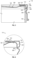
- FIG. 6 illustrates a detailed view of one example of the seal releasing assembly 110 of FIG. 4 at the line B.
- the lid 120 includes a lid peak 600 such as at the transition from the lid wall 210 to the lid edge 220.
- the lid peak 600 is aligned with the lid wall 210.
- the lid peak 600 is produced by beveling the lid edge 220.
- the lid peak 600 prevents slipping between the release ridge 260 and the lid edge 220 and accordingly assists in biasing the lid 120 away from the container 100.
- the release ridge 260 is configured for engagement with the lid peak 600 to bias the lid surface 200 away from the container 100.
- the lid peak 600 and the release ridge 260 include complementary surfaces (e.g., knurled, surface to surface engagement opposed to a slipping direction or the like) that promote engagement of the ridge to the lid peak 600 to ensure bias of the lid 120 away from the container 100 is provided by the ring 130.
- the release ridge 260 is optionally configured to slide over the lid peak 600 (even with engagement promoting complementary surfaces), for instance, with pressure applied to the lid 120 and toward the container 100 by hand, as the retaining and releasing ring 130 transitions from the release-ready configuration to the decoupling configuration.
- Figure 7 illustrates one example of a method 700 for releasing a container seal.
- the reference numerals provided are exemplary and are not exclusive.
- components, features, functions, operations and the like described in the method 1000 include, but are not limited to, the corresponding numbered elements provided herein and other corresponding elements described herein (both numbered and unnumbered) as well as their equivalents.
- a release ridge 260 of a retaining and releasing ring 130 is slid along a lid wall 210 of a lid 120.
- the release ridge is seated beneath a lid edge 220 of the lid.
- the lid edge 220 is optionally configured to slidably disengage from the release ridge 260 (e.g., during coupling of the ring 130 with the lid and container or during decoupling of the ring 130 from the lid and container).
- the retaining and release ring is moved relative to the lid coupled with a container 100 at a seal (e.g., a portion of the container 100 that surrounds the container opening 105).
- the seal is released according to movement of the retaining and release ring.
- Release of the seal includes engaging the retaining and releasing ring 130 with the lid 120 and biasing the lid away from the container 100 using the ring.
- a release ridge 260 of the retaining and release ring 130 is engaged and presses against a lid edge 220 of the lid 120.
- Release of the seal optionally includes biasing the lid away from the container with movement of the retaining and release ring relative to the container. For instance, relative movement between threading of the ring 130 and the container 100 moves the ring 130 and its release ridge 260 into engagement with the lid edge 220, and continued movement biases the lid 120 from the container to release the seal.
- the method 700 includes decoupling the retaining and releasing ring from the lid.
- decoupling the retaining and releasing ring includes sliding the release ridge of the retaining and releasing ring along the lid wall 210 toward a lid surface (e.g., the lid surface 200 of Figures 2-5 ) opposed to the lid edge.
- decoupling the retaining and releasing ring 130 includes disengaging the release ridge 260 from the lid wall with the release ridge above the lid surface.
- sliding the release ridge along the lid wall and seating the release ridge beneath the lid edge include biasing the release ridge 260 toward the lid wall with a ring wall (e.g., the ring wall 240 of Figures 1-2 and 4-6 ) of the retaining and releasing ring.
- sliding the release ridge of the retaining and releasing ring along the lid wall includes sliding the release ridge of the retaining and releasing ring along the lid wall with the lid coupled with the container at the seal.
- the lid remains coupled to the container at the seal while the release ridge is slid along the lid wall, for instance with pressure applied to the lid 120 by hand, tool or the like toward the container 100.
- Geometric terms such as “parallel”, “perpendicular”, “round”, or “square”, are not intended to require absolute mathematical precision, unless the context indicates otherwise. Instead, such geometric terms allow for variations due to manufacturing or equivalent functions. For example, if an element is described as “round” or “generally round,” a component that is not precisely circular (e.g., one that is slightly oblong or is a many-sided polygon) is still encompassed by this description.
Landscapes
- Engineering & Computer Science (AREA)
- Mechanical Engineering (AREA)
- Closures For Containers (AREA)
Claims (12)
- Dichtungsfreigebende Verschlussanordnung (110), umfassend:einen Deckel (120), der eingerichtet ist, über eine Behälteröffnung (105) eines Behälters (100) gekoppelt zu sein, wobei der Deckel (120) aufweist:eine Deckeloberfläche (200),eine Deckelwand (210), die sich von der Deckeloberfläche (200) aus erstreckt, wobei die Deckelwand (210) einen Deckelrand (220) und eine verschiebbare Kopplungsoberfläche (215) zwischen dem Deckelrand (220) und der Deckeloberfläche (200) aufweist, und eine Deckelspitze (600), die mit der Deckelwand (210) ausgerichtet ist;einen Halte- und Freigabering (130), der zur Verbindung mit dem Behälter (100) und dem Deckel (120) eingerichtet ist, wobei der Halte- und Freigabering (130) aufweist:einen Ringflansch (230), der sich über mindestens einen Teil der Deckeloberfläche (200) erstreckt,eine Freigaberippe (260), undeine Ringwand (240), die sich von dem Ringflansch (230) zur Freigaberippe (260) erstreckt und die Freigaberippe (260) nach innen in Richtung der Deckelwand (210) vorspannt,dadurch gekennzeichnet, dassder Halte- und Freigabering (130) Entkopplungs- und freigabebereite Konfigurationen aufweist, wobeiin der Entkopplungskonfiguration der Freigaberippe (260) gleitend entlang der Deckelwand (210) gekoppelt ist, undin der freigabebereiten Konfiguration die Freigaberippe (260) unter dem Deckelrand (220) sitzt und gleitend von der Deckelwand (210) gelöst ist, undwobei die Freigaberippe (260) eingerichtet ist, über die Deckelspitze (600) zu gleiten, wenn der Halte- und Freigabering (130) von der freigabebereiten Konfiguration in die Entkopplungskonfiguration übergeht.
- Anordnung (110) nach Anspruch 1, wobei in der freigabebereiten Konfiguration der Eingriff der Freigaberippe (260) mit dem Deckelrand (220) so eingerichtet ist, dass die Deckeloberfläche (200) vom Behälter (100) weg vorgespannt wird.
- Anordnung (110) nach Anspruch 1, wobei der Halte- und Freigaberings (130) einen Gewindesicke (250) aufweist und die Ringwand (240) sich von dem Ringflansch (230) zu der Gewindesicke (250) erstreckt.
- Anordnung (110) nach Anspruch 3, wobei sich die Freigaberippe (260) zwischen dem Ringflansch (230) und der Gewindesicke (250) befindet.
- Anordnung (110) nach Anspruch 1, wobei die Freigaberippe (260) für einen Eingriff mit der Deckelspitze (600) eingerichtet ist, um die Deckeloberfläche (200) vom Behälter (100) weg vorzuspannen.
- Anordnung (110) nach Anspruch 1, wobei die Freigaberippe (260) eingerichtet ist, über den Deckelrand (220) zu gleiten, wenn der Halte- und Freigabering (130) von der freigabebereiten Konfiguration in die Entkopplungskonfiguration übergeht.
- Anordnung (110) nach Anspruch 1, wobei der Halte- und Freigaberings (130) eine entkoppelte Konfiguration aufweist und in der entkoppelten Konfiguration die Freigaberippe (260) über der Deckeloberfläche (200) liegt und gleitend von der Deckelwand (210) gelöst ist.
- Anordnung (110) nach Anspruch 1, wobei die Ringwand (240) die Freigaberippe (260) in der Entkopplungskonfiguration in Richtung der Deckelwand (210) vorspannt und die Ringwand (240) eingerichtet ist, die Freigaberippe (260) so vorzuspannen, dass sie unter dem Deckelrand (220) sitzt, wenn die Freigaberippe (260) von der Entkopplungskonfiguration in die freigabebereite Konfiguration übergeht.
- Verfahren zur Verwendung der dichtungsfreigebenden Verschlussanordnung nach Anspruch 1, wobei das Verfahren umfasst:- Bereitstellen eines Behälters, der mit dem Deckel (120) an einer Dichtung verbunden ist,- Koppeln des Halte- und Freigaberings (130) mit dem Deckel (120) und dem Behälter (100) durch Schieben der Freigaberippe (260) des Halte- und Freigaberings (130) entlang der Deckelwand (210) des Deckels (120),
Setzen der Freigaberippe (260) unter den Deckelrand (220) des Deckels (120), wobei die Freigaberippe (260) gleitend von der Deckelwand (210) gelöst wird, und Bewegen des Halte- und Freigabesrings relativ zum Deckel (120);- Entkoppeln des Halte- und Freigaberings (130) von dem Deckel (120), wobei das Entkoppeln das Gleiten der Freigaberippe (260) über die Deckelspitze (600) des Deckels (120) einschließt. - Verfahren nach Anspruch 9, umfassend:- Freigeben der Dichtung zwischen dem Deckel (120) und dem Behälter (100) entsprechend der Bewegung des Halte- und Freigaberings (130), wobei das Freigeben umfasst:Einrücken der Freigaberippe (260) des Halte- und Freigaberings (130) mit dem Deckelrand (220) des Deckels (120), undWegdrücken des Deckels (120) vom Behälter (100) durch Bewegung des Halte- und Freigaberings (130) relativ zum Behälter (100), wobei die Freigaberippe (260) mit dem Deckelrand (220) in Eingriff steht.
- Verfahren nach Anspruch 9 oder 10, wobei das Entkoppeln des Halte- und Freigaberings (130) umfasst:Gleiten der Freigaberippe (260) des Halte- und Freigaberings (130) entlang der Deckelwand (210) in Richtung einer dem Deckelrand (220) gegenüberliegenden Deckeloberfläche (200), undLösen der Freigaberippe (260) von der Deckelwand (210), wobei sich die Freigaberippe (260) über der Deckeloberfläche (200) befindet.
- Verfahren nach Anspruch 9 oder 10, wobei das Gleiten der Freigaberippe (260) entlang der Deckelwand (210) und das Setzen der Freigaberippe (260) unter den Deckelrand (220) das Vorspannen der Freigaberippe (260) in Richtung der Deckelwand (210) mit der Ringwand (240) des Halte- und Freigaberings (130) umfasst.
Applications Claiming Priority (2)
| Application Number | Priority Date | Filing Date | Title |
|---|---|---|---|
| US201662431117P | 2016-12-07 | 2016-12-07 | |
| PCT/US2017/065179 WO2018106960A1 (en) | 2016-12-07 | 2017-12-07 | Seal releasing closure assembly |
Publications (4)
| Publication Number | Publication Date |
|---|---|
| EP3551544A1 EP3551544A1 (de) | 2019-10-16 |
| EP3551544A4 EP3551544A4 (de) | 2020-09-09 |
| EP3551544C0 EP3551544C0 (de) | 2024-03-06 |
| EP3551544B1 true EP3551544B1 (de) | 2024-03-06 |
Family
ID=62491370
Family Applications (1)
| Application Number | Title | Priority Date | Filing Date |
|---|---|---|---|
| EP17878896.4A Active EP3551544B1 (de) | 2016-12-07 | 2017-12-07 | Dichtungsfreisetzende verschlussanordnung |
Country Status (6)
| Country | Link |
|---|---|
| US (1) | US11365035B2 (de) |
| EP (1) | EP3551544B1 (de) |
| AU (1) | AU2017370714B2 (de) |
| MX (1) | MX2019006521A (de) |
| WO (1) | WO2018106960A1 (de) |
| ZA (1) | ZA201902889B (de) |
Families Citing this family (2)
| Publication number | Priority date | Publication date | Assignee | Title |
|---|---|---|---|---|
| GB0909189D0 (en) * | 2009-05-29 | 2009-07-15 | Crown Packaging Technology Inc | Closure assembly |
| MX2019006521A (es) | 2016-12-07 | 2019-12-16 | Tecnocap Llc | Montaje de cierre de liberacion de sello. |
Family Cites Families (13)
| Publication number | Priority date | Publication date | Assignee | Title |
|---|---|---|---|---|
| IT953394B (it) * | 1972-03-23 | 1973-08-10 | Podesta A | Capsula metallica a vite od a baionetta con fondello separato per la chiusura dei recipienti |
| US4694969A (en) * | 1983-11-17 | 1987-09-22 | Aci Australia Limited | Container closure |
| EP0269920A1 (de) * | 1986-11-20 | 1988-06-08 | Anchor Hocking Corporation | Zusammengesetzter Verschluss und Behälter |
| US5443853A (en) * | 1991-05-01 | 1995-08-22 | Anchor Hocking Packaging Co. | Press-on, pry-off closure for microwavable vacuum sealed container |
| US5803298A (en) * | 1995-01-10 | 1998-09-08 | Hausmann; Donald H. | Container and container lid assembly with retaining ring |
| US6276543B1 (en) | 1999-05-19 | 2001-08-21 | Crown Cork & Seal Technologies Corporation | Vented composite closure |
| US7134565B1 (en) * | 2001-02-22 | 2006-11-14 | Crown Cork & Seal Technologies | Closure having band with internal thread formed by impression |
| US7014060B2 (en) | 2002-07-19 | 2006-03-21 | Ball Corporation | Twist opening sealing container |
| EP1686070A1 (de) * | 2005-01-26 | 2006-08-02 | Plato product consultants V.O.F. | Leicht zu öffnender Verschluss |
| CN101977821B (zh) | 2008-03-20 | 2014-10-29 | 皇冠包装技术公司 | 封闭件 |
| US9487358B2 (en) | 2008-09-22 | 2016-11-08 | The Cincinnati Mine Machinery Company | Conveyor chain |
| US9315306B2 (en) | 2013-11-01 | 2016-04-19 | Silgan White Cap LLC | Composite closure |
| MX2019006521A (es) | 2016-12-07 | 2019-12-16 | Tecnocap Llc | Montaje de cierre de liberacion de sello. |
-
2017
- 2017-12-07 MX MX2019006521A patent/MX2019006521A/es unknown
- 2017-12-07 WO PCT/US2017/065179 patent/WO2018106960A1/en not_active Ceased
- 2017-12-07 US US16/466,578 patent/US11365035B2/en active Active
- 2017-12-07 EP EP17878896.4A patent/EP3551544B1/de active Active
- 2017-12-07 AU AU2017370714A patent/AU2017370714B2/en active Active
-
2019
- 2019-05-09 ZA ZA2019/02889A patent/ZA201902889B/en unknown
Also Published As
| Publication number | Publication date |
|---|---|
| EP3551544A1 (de) | 2019-10-16 |
| MX2019006521A (es) | 2019-12-16 |
| BR112019010293A2 (pt) | 2019-09-03 |
| ZA201902889B (en) | 2021-10-27 |
| AU2017370714B2 (en) | 2020-02-27 |
| EP3551544C0 (de) | 2024-03-06 |
| NZ753298A (en) | 2020-10-30 |
| EP3551544A4 (de) | 2020-09-09 |
| AU2017370714A1 (en) | 2019-05-30 |
| US20190344941A1 (en) | 2019-11-14 |
| WO2018106960A1 (en) | 2018-06-14 |
| US11365035B2 (en) | 2022-06-21 |
Similar Documents
| Publication | Publication Date | Title |
|---|---|---|
| EP1365972B1 (de) | Einweg-getränkebehälter mit einem deckel | |
| EP3403943B1 (de) | Kombination aus metalldeckel und dichtung zur bewahrung der form eines kunststoffbehälterhalses | |
| US10934060B2 (en) | Multi-chamber tube container and cap | |
| EP1951583A1 (de) | Behälter | |
| US7568586B2 (en) | Easy open container closure | |
| EP3551544B1 (de) | Dichtungsfreisetzende verschlussanordnung | |
| US7832581B2 (en) | Closure and methods for placing and removing such a closure | |
| AU2010286317B2 (en) | Closure with obliquely angled cam surfaces on inner and outer parts | |
| CN107000903A (zh) | 用于容器的盖子和包括此类盖子的包装 | |
| US7628288B2 (en) | Resilient and deformable container lid | |
| US4595111A (en) | Device for removing a flexible cap from a cylindrical neck | |
| CA3111606A1 (en) | Tethered plastic stopper | |
| EP3296222A1 (de) | Deckel für eine lebensmittelverpackung | |
| EP0958194B1 (de) | Originalitätssicherung eines mehrwegverschlussystems | |
| US9725215B2 (en) | Container that prevents illegal operation and can be easily identified after being illegally operated | |
| EP4371901A1 (de) | Originalitätsverschlusssystem mit metallischem behälter und kunststoffverschluss | |
| BR112019010293B1 (pt) | Conjunto de encerramento de liberação de vedação | |
| GB2441327A (en) | Container lid for persons of limited strength and/or manual motor skills | |
| NZ753298B2 (en) | Seal releasing closure assembly | |
| AU2017100889A4 (en) | A closure for a vessel | |
| CA2479825C (en) | Crimp top seal for vials | |
| GB2517205A (en) | Closure Assembly |
Legal Events
| Date | Code | Title | Description |
|---|---|---|---|
| STAA | Information on the status of an ep patent application or granted ep patent |
Free format text: STATUS: THE INTERNATIONAL PUBLICATION HAS BEEN MADE |
|
| PUAI | Public reference made under article 153(3) epc to a published international application that has entered the european phase |
Free format text: ORIGINAL CODE: 0009012 |
|
| STAA | Information on the status of an ep patent application or granted ep patent |
Free format text: STATUS: REQUEST FOR EXAMINATION WAS MADE |
|
| 17P | Request for examination filed |
Effective date: 20190628 |
|
| AK | Designated contracting states |
Kind code of ref document: A1 Designated state(s): AL AT BE BG CH CY CZ DE DK EE ES FI FR GB GR HR HU IE IS IT LI LT LU LV MC MK MT NL NO PL PT RO RS SE SI SK SM TR |
|
| AX | Request for extension of the european patent |
Extension state: BA ME |
|
| DAV | Request for validation of the european patent (deleted) | ||
| DAX | Request for extension of the european patent (deleted) | ||
| A4 | Supplementary search report drawn up and despatched |
Effective date: 20200807 |
|
| RIC1 | Information provided on ipc code assigned before grant |
Ipc: B65D 79/00 20060101ALI20200803BHEP Ipc: B65D 45/30 20060101ALI20200803BHEP Ipc: B65D 43/02 20060101AFI20200803BHEP Ipc: B65D 51/14 20060101ALI20200803BHEP Ipc: B65D 39/08 20060101ALI20200803BHEP |
|
| STAA | Information on the status of an ep patent application or granted ep patent |
Free format text: STATUS: EXAMINATION IS IN PROGRESS |
|
| 17Q | First examination report despatched |
Effective date: 20210826 |
|
| GRAP | Despatch of communication of intention to grant a patent |
Free format text: ORIGINAL CODE: EPIDOSNIGR1 |
|
| STAA | Information on the status of an ep patent application or granted ep patent |
Free format text: STATUS: GRANT OF PATENT IS INTENDED |
|
| INTG | Intention to grant announced |
Effective date: 20230929 |
|
| GRAS | Grant fee paid |
Free format text: ORIGINAL CODE: EPIDOSNIGR3 |
|
| GRAA | (expected) grant |
Free format text: ORIGINAL CODE: 0009210 |
|
| STAA | Information on the status of an ep patent application or granted ep patent |
Free format text: STATUS: THE PATENT HAS BEEN GRANTED |
|
| AK | Designated contracting states |
Kind code of ref document: B1 Designated state(s): AL AT BE BG CH CY CZ DE DK EE ES FI FR GB GR HR HU IE IS IT LI LT LU LV MC MK MT NL NO PL PT RO RS SE SI SK SM TR |
|
| REG | Reference to a national code |
Ref country code: GB Ref legal event code: FG4D |
|
| REG | Reference to a national code |
Ref country code: CH Ref legal event code: EP |
|
| REG | Reference to a national code |
Ref country code: IE Ref legal event code: FG4D |
|
| REG | Reference to a national code |
Ref country code: DE Ref legal event code: R096 Ref document number: 602017079868 Country of ref document: DE |
|
| U01 | Request for unitary effect filed |
Effective date: 20240403 |
|
| U07 | Unitary effect registered |
Designated state(s): AT BE BG DE DK EE FI FR IT LT LU LV MT NL PT SE SI Effective date: 20240411 |
|
| PG25 | Lapsed in a contracting state [announced via postgrant information from national office to epo] |
Ref country code: GR Free format text: LAPSE BECAUSE OF FAILURE TO SUBMIT A TRANSLATION OF THE DESCRIPTION OR TO PAY THE FEE WITHIN THE PRESCRIBED TIME-LIMIT Effective date: 20240607 |
|
| PG25 | Lapsed in a contracting state [announced via postgrant information from national office to epo] |
Ref country code: RS Free format text: LAPSE BECAUSE OF FAILURE TO SUBMIT A TRANSLATION OF THE DESCRIPTION OR TO PAY THE FEE WITHIN THE PRESCRIBED TIME-LIMIT Effective date: 20240606 Ref country code: HR Free format text: LAPSE BECAUSE OF FAILURE TO SUBMIT A TRANSLATION OF THE DESCRIPTION OR TO PAY THE FEE WITHIN THE PRESCRIBED TIME-LIMIT Effective date: 20240306 |
|
| PG25 | Lapsed in a contracting state [announced via postgrant information from national office to epo] |
Ref country code: ES Free format text: LAPSE BECAUSE OF FAILURE TO SUBMIT A TRANSLATION OF THE DESCRIPTION OR TO PAY THE FEE WITHIN THE PRESCRIBED TIME-LIMIT Effective date: 20240306 |
|
| PG25 | Lapsed in a contracting state [announced via postgrant information from national office to epo] |
Ref country code: RS Free format text: LAPSE BECAUSE OF FAILURE TO SUBMIT A TRANSLATION OF THE DESCRIPTION OR TO PAY THE FEE WITHIN THE PRESCRIBED TIME-LIMIT Effective date: 20240606 Ref country code: NO Free format text: LAPSE BECAUSE OF FAILURE TO SUBMIT A TRANSLATION OF THE DESCRIPTION OR TO PAY THE FEE WITHIN THE PRESCRIBED TIME-LIMIT Effective date: 20240606 Ref country code: HR Free format text: LAPSE BECAUSE OF FAILURE TO SUBMIT A TRANSLATION OF THE DESCRIPTION OR TO PAY THE FEE WITHIN THE PRESCRIBED TIME-LIMIT Effective date: 20240306 Ref country code: GR Free format text: LAPSE BECAUSE OF FAILURE TO SUBMIT A TRANSLATION OF THE DESCRIPTION OR TO PAY THE FEE WITHIN THE PRESCRIBED TIME-LIMIT Effective date: 20240607 Ref country code: ES Free format text: LAPSE BECAUSE OF FAILURE TO SUBMIT A TRANSLATION OF THE DESCRIPTION OR TO PAY THE FEE WITHIN THE PRESCRIBED TIME-LIMIT Effective date: 20240306 |
|
| PG25 | Lapsed in a contracting state [announced via postgrant information from national office to epo] |
Ref country code: IS Free format text: LAPSE BECAUSE OF FAILURE TO SUBMIT A TRANSLATION OF THE DESCRIPTION OR TO PAY THE FEE WITHIN THE PRESCRIBED TIME-LIMIT Effective date: 20240706 |
|
| PG25 | Lapsed in a contracting state [announced via postgrant information from national office to epo] |
Ref country code: SM Free format text: LAPSE BECAUSE OF FAILURE TO SUBMIT A TRANSLATION OF THE DESCRIPTION OR TO PAY THE FEE WITHIN THE PRESCRIBED TIME-LIMIT Effective date: 20240306 |
|
| PG25 | Lapsed in a contracting state [announced via postgrant information from national office to epo] |
Ref country code: PL Free format text: LAPSE BECAUSE OF FAILURE TO SUBMIT A TRANSLATION OF THE DESCRIPTION OR TO PAY THE FEE WITHIN THE PRESCRIBED TIME-LIMIT Effective date: 20240306 |
|
| PG25 | Lapsed in a contracting state [announced via postgrant information from national office to epo] |
Ref country code: SK Free format text: LAPSE BECAUSE OF FAILURE TO SUBMIT A TRANSLATION OF THE DESCRIPTION OR TO PAY THE FEE WITHIN THE PRESCRIBED TIME-LIMIT Effective date: 20240306 |
|
| PG25 | Lapsed in a contracting state [announced via postgrant information from national office to epo] |
Ref country code: SM Free format text: LAPSE BECAUSE OF FAILURE TO SUBMIT A TRANSLATION OF THE DESCRIPTION OR TO PAY THE FEE WITHIN THE PRESCRIBED TIME-LIMIT Effective date: 20240306 Ref country code: SK Free format text: LAPSE BECAUSE OF FAILURE TO SUBMIT A TRANSLATION OF THE DESCRIPTION OR TO PAY THE FEE WITHIN THE PRESCRIBED TIME-LIMIT Effective date: 20240306 Ref country code: RO Free format text: LAPSE BECAUSE OF FAILURE TO SUBMIT A TRANSLATION OF THE DESCRIPTION OR TO PAY THE FEE WITHIN THE PRESCRIBED TIME-LIMIT Effective date: 20240306 Ref country code: PL Free format text: LAPSE BECAUSE OF FAILURE TO SUBMIT A TRANSLATION OF THE DESCRIPTION OR TO PAY THE FEE WITHIN THE PRESCRIBED TIME-LIMIT Effective date: 20240306 Ref country code: IS Free format text: LAPSE BECAUSE OF FAILURE TO SUBMIT A TRANSLATION OF THE DESCRIPTION OR TO PAY THE FEE WITHIN THE PRESCRIBED TIME-LIMIT Effective date: 20240706 |
|
| REG | Reference to a national code |
Ref country code: DE Ref legal event code: R097 Ref document number: 602017079868 Country of ref document: DE |
|
| PLBE | No opposition filed within time limit |
Free format text: ORIGINAL CODE: 0009261 |
|
| STAA | Information on the status of an ep patent application or granted ep patent |
Free format text: STATUS: NO OPPOSITION FILED WITHIN TIME LIMIT |
|
| U20 | Renewal fee for the european patent with unitary effect paid |
Year of fee payment: 8 Effective date: 20241211 |
|
| 26N | No opposition filed |
Effective date: 20241209 |
|
| PG25 | Lapsed in a contracting state [announced via postgrant information from national office to epo] |
Ref country code: MC Free format text: LAPSE BECAUSE OF FAILURE TO SUBMIT A TRANSLATION OF THE DESCRIPTION OR TO PAY THE FEE WITHIN THE PRESCRIBED TIME-LIMIT Effective date: 20240306 |
|
| REG | Reference to a national code |
Ref country code: CH Ref legal event code: PL |
|
| PG25 | Lapsed in a contracting state [announced via postgrant information from national office to epo] |
Ref country code: CH Free format text: LAPSE BECAUSE OF NON-PAYMENT OF DUE FEES Effective date: 20241231 |
|
| PG25 | Lapsed in a contracting state [announced via postgrant information from national office to epo] |
Ref country code: IE Free format text: LAPSE BECAUSE OF NON-PAYMENT OF DUE FEES Effective date: 20241207 |
|
| U20 | Renewal fee for the european patent with unitary effect paid |
Year of fee payment: 9 Effective date: 20251127 |
|
| PGFP | Annual fee paid to national office [announced via postgrant information from national office to epo] |
Ref country code: GB Payment date: 20251126 Year of fee payment: 9 |
|
| PGFP | Annual fee paid to national office [announced via postgrant information from national office to epo] |
Ref country code: CZ Payment date: 20251126 Year of fee payment: 9 |
|
| PG25 | Lapsed in a contracting state [announced via postgrant information from national office to epo] |
Ref country code: CY Free format text: LAPSE BECAUSE OF FAILURE TO SUBMIT A TRANSLATION OF THE DESCRIPTION OR TO PAY THE FEE WITHIN THE PRESCRIBED TIME-LIMIT; INVALID AB INITIO Effective date: 20171207 |