EP3551515B1 - Pneumatischer bremskraftverstärker mit einem abdichtelement - Google Patents
Pneumatischer bremskraftverstärker mit einem abdichtelement Download PDFInfo
- Publication number
- EP3551515B1 EP3551515B1 EP17801439.5A EP17801439A EP3551515B1 EP 3551515 B1 EP3551515 B1 EP 3551515B1 EP 17801439 A EP17801439 A EP 17801439A EP 3551515 B1 EP3551515 B1 EP 3551515B1
- Authority
- EP
- European Patent Office
- Prior art keywords
- brake booster
- shell
- clamping space
- wall
- shell elements
- Prior art date
- Legal status (The legal status is an assumption and is not a legal conclusion. Google has not performed a legal analysis and makes no representation as to the accuracy of the status listed.)
- Active
Links
Images

Classifications
-
- B—PERFORMING OPERATIONS; TRANSPORTING
- B60—VEHICLES IN GENERAL
- B60T—VEHICLE BRAKE CONTROL SYSTEMS OR PARTS THEREOF; BRAKE CONTROL SYSTEMS OR PARTS THEREOF, IN GENERAL; ARRANGEMENT OF BRAKING ELEMENTS ON VEHICLES IN GENERAL; PORTABLE DEVICES FOR PREVENTING UNWANTED MOVEMENT OF VEHICLES; VEHICLE MODIFICATIONS TO FACILITATE COOLING OF BRAKES
- B60T11/00—Transmitting braking action from initiating means to ultimate brake actuator without power assistance or drive or where such assistance or drive is irrelevant
- B60T11/10—Transmitting braking action from initiating means to ultimate brake actuator without power assistance or drive or where such assistance or drive is irrelevant transmitting by fluid means, e.g. hydraulic
- B60T11/16—Master control, e.g. master cylinders
-
- B—PERFORMING OPERATIONS; TRANSPORTING
- B60—VEHICLES IN GENERAL
- B60T—VEHICLE BRAKE CONTROL SYSTEMS OR PARTS THEREOF; BRAKE CONTROL SYSTEMS OR PARTS THEREOF, IN GENERAL; ARRANGEMENT OF BRAKING ELEMENTS ON VEHICLES IN GENERAL; PORTABLE DEVICES FOR PREVENTING UNWANTED MOVEMENT OF VEHICLES; VEHICLE MODIFICATIONS TO FACILITATE COOLING OF BRAKES
- B60T11/00—Transmitting braking action from initiating means to ultimate brake actuator without power assistance or drive or where such assistance or drive is irrelevant
- B60T11/10—Transmitting braking action from initiating means to ultimate brake actuator without power assistance or drive or where such assistance or drive is irrelevant transmitting by fluid means, e.g. hydraulic
- B60T11/16—Master control, e.g. master cylinders
- B60T11/18—Connection thereof to initiating means
-
- B—PERFORMING OPERATIONS; TRANSPORTING
- B60—VEHICLES IN GENERAL
- B60T—VEHICLE BRAKE CONTROL SYSTEMS OR PARTS THEREOF; BRAKE CONTROL SYSTEMS OR PARTS THEREOF, IN GENERAL; ARRANGEMENT OF BRAKING ELEMENTS ON VEHICLES IN GENERAL; PORTABLE DEVICES FOR PREVENTING UNWANTED MOVEMENT OF VEHICLES; VEHICLE MODIFICATIONS TO FACILITATE COOLING OF BRAKES
- B60T13/00—Transmitting braking action from initiating means to ultimate brake actuator with power assistance or drive; Brake systems incorporating such transmitting means, e.g. air-pressure brake systems
- B60T13/10—Transmitting braking action from initiating means to ultimate brake actuator with power assistance or drive; Brake systems incorporating such transmitting means, e.g. air-pressure brake systems with fluid assistance, drive, or release
- B60T13/12—Transmitting braking action from initiating means to ultimate brake actuator with power assistance or drive; Brake systems incorporating such transmitting means, e.g. air-pressure brake systems with fluid assistance, drive, or release the fluid being liquid
- B60T13/14—Transmitting braking action from initiating means to ultimate brake actuator with power assistance or drive; Brake systems incorporating such transmitting means, e.g. air-pressure brake systems with fluid assistance, drive, or release the fluid being liquid using accumulators or reservoirs fed by pumps
- B60T13/142—Systems with master cylinder
- B60T13/143—Master cylinder mechanically coupled with booster
-
- B—PERFORMING OPERATIONS; TRANSPORTING
- B60—VEHICLES IN GENERAL
- B60T—VEHICLE BRAKE CONTROL SYSTEMS OR PARTS THEREOF; BRAKE CONTROL SYSTEMS OR PARTS THEREOF, IN GENERAL; ARRANGEMENT OF BRAKING ELEMENTS ON VEHICLES IN GENERAL; PORTABLE DEVICES FOR PREVENTING UNWANTED MOVEMENT OF VEHICLES; VEHICLE MODIFICATIONS TO FACILITATE COOLING OF BRAKES
- B60T13/00—Transmitting braking action from initiating means to ultimate brake actuator with power assistance or drive; Brake systems incorporating such transmitting means, e.g. air-pressure brake systems
- B60T13/10—Transmitting braking action from initiating means to ultimate brake actuator with power assistance or drive; Brake systems incorporating such transmitting means, e.g. air-pressure brake systems with fluid assistance, drive, or release
- B60T13/12—Transmitting braking action from initiating means to ultimate brake actuator with power assistance or drive; Brake systems incorporating such transmitting means, e.g. air-pressure brake systems with fluid assistance, drive, or release the fluid being liquid
- B60T13/14—Transmitting braking action from initiating means to ultimate brake actuator with power assistance or drive; Brake systems incorporating such transmitting means, e.g. air-pressure brake systems with fluid assistance, drive, or release the fluid being liquid using accumulators or reservoirs fed by pumps
- B60T13/142—Systems with master cylinder
- B60T13/143—Master cylinder mechanically coupled with booster
- B60T13/144—Pilot valve provided inside booster piston
-
- B—PERFORMING OPERATIONS; TRANSPORTING
- B60—VEHICLES IN GENERAL
- B60T—VEHICLE BRAKE CONTROL SYSTEMS OR PARTS THEREOF; BRAKE CONTROL SYSTEMS OR PARTS THEREOF, IN GENERAL; ARRANGEMENT OF BRAKING ELEMENTS ON VEHICLES IN GENERAL; PORTABLE DEVICES FOR PREVENTING UNWANTED MOVEMENT OF VEHICLES; VEHICLE MODIFICATIONS TO FACILITATE COOLING OF BRAKES
- B60T13/00—Transmitting braking action from initiating means to ultimate brake actuator with power assistance or drive; Brake systems incorporating such transmitting means, e.g. air-pressure brake systems
- B60T13/10—Transmitting braking action from initiating means to ultimate brake actuator with power assistance or drive; Brake systems incorporating such transmitting means, e.g. air-pressure brake systems with fluid assistance, drive, or release
- B60T13/12—Transmitting braking action from initiating means to ultimate brake actuator with power assistance or drive; Brake systems incorporating such transmitting means, e.g. air-pressure brake systems with fluid assistance, drive, or release the fluid being liquid
- B60T13/14—Transmitting braking action from initiating means to ultimate brake actuator with power assistance or drive; Brake systems incorporating such transmitting means, e.g. air-pressure brake systems with fluid assistance, drive, or release the fluid being liquid using accumulators or reservoirs fed by pumps
- B60T13/142—Systems with master cylinder
- B60T13/145—Master cylinder integrated or hydraulically coupled with booster
-
- B—PERFORMING OPERATIONS; TRANSPORTING
- B60—VEHICLES IN GENERAL
- B60T—VEHICLE BRAKE CONTROL SYSTEMS OR PARTS THEREOF; BRAKE CONTROL SYSTEMS OR PARTS THEREOF, IN GENERAL; ARRANGEMENT OF BRAKING ELEMENTS ON VEHICLES IN GENERAL; PORTABLE DEVICES FOR PREVENTING UNWANTED MOVEMENT OF VEHICLES; VEHICLE MODIFICATIONS TO FACILITATE COOLING OF BRAKES
- B60T13/00—Transmitting braking action from initiating means to ultimate brake actuator with power assistance or drive; Brake systems incorporating such transmitting means, e.g. air-pressure brake systems
- B60T13/10—Transmitting braking action from initiating means to ultimate brake actuator with power assistance or drive; Brake systems incorporating such transmitting means, e.g. air-pressure brake systems with fluid assistance, drive, or release
- B60T13/12—Transmitting braking action from initiating means to ultimate brake actuator with power assistance or drive; Brake systems incorporating such transmitting means, e.g. air-pressure brake systems with fluid assistance, drive, or release the fluid being liquid
- B60T13/16—Transmitting braking action from initiating means to ultimate brake actuator with power assistance or drive; Brake systems incorporating such transmitting means, e.g. air-pressure brake systems with fluid assistance, drive, or release the fluid being liquid using pumps directly, i.e. without interposition of accumulators or reservoirs
- B60T13/161—Systems with master cylinder
- B60T13/162—Master cylinder mechanically coupled with booster
-
- B—PERFORMING OPERATIONS; TRANSPORTING
- B60—VEHICLES IN GENERAL
- B60T—VEHICLE BRAKE CONTROL SYSTEMS OR PARTS THEREOF; BRAKE CONTROL SYSTEMS OR PARTS THEREOF, IN GENERAL; ARRANGEMENT OF BRAKING ELEMENTS ON VEHICLES IN GENERAL; PORTABLE DEVICES FOR PREVENTING UNWANTED MOVEMENT OF VEHICLES; VEHICLE MODIFICATIONS TO FACILITATE COOLING OF BRAKES
- B60T13/00—Transmitting braking action from initiating means to ultimate brake actuator with power assistance or drive; Brake systems incorporating such transmitting means, e.g. air-pressure brake systems
- B60T13/10—Transmitting braking action from initiating means to ultimate brake actuator with power assistance or drive; Brake systems incorporating such transmitting means, e.g. air-pressure brake systems with fluid assistance, drive, or release
- B60T13/12—Transmitting braking action from initiating means to ultimate brake actuator with power assistance or drive; Brake systems incorporating such transmitting means, e.g. air-pressure brake systems with fluid assistance, drive, or release the fluid being liquid
- B60T13/16—Transmitting braking action from initiating means to ultimate brake actuator with power assistance or drive; Brake systems incorporating such transmitting means, e.g. air-pressure brake systems with fluid assistance, drive, or release the fluid being liquid using pumps directly, i.e. without interposition of accumulators or reservoirs
- B60T13/161—Systems with master cylinder
- B60T13/165—Master cylinder integrated or hydraulically coupled with booster
-
- B—PERFORMING OPERATIONS; TRANSPORTING
- B60—VEHICLES IN GENERAL
- B60T—VEHICLE BRAKE CONTROL SYSTEMS OR PARTS THEREOF; BRAKE CONTROL SYSTEMS OR PARTS THEREOF, IN GENERAL; ARRANGEMENT OF BRAKING ELEMENTS ON VEHICLES IN GENERAL; PORTABLE DEVICES FOR PREVENTING UNWANTED MOVEMENT OF VEHICLES; VEHICLE MODIFICATIONS TO FACILITATE COOLING OF BRAKES
- B60T13/00—Transmitting braking action from initiating means to ultimate brake actuator with power assistance or drive; Brake systems incorporating such transmitting means, e.g. air-pressure brake systems
- B60T13/10—Transmitting braking action from initiating means to ultimate brake actuator with power assistance or drive; Brake systems incorporating such transmitting means, e.g. air-pressure brake systems with fluid assistance, drive, or release
- B60T13/24—Transmitting braking action from initiating means to ultimate brake actuator with power assistance or drive; Brake systems incorporating such transmitting means, e.g. air-pressure brake systems with fluid assistance, drive, or release the fluid being gaseous
- B60T13/26—Compressed-air systems
- B60T13/40—Compressed-air systems indirect, i.e. compressed air booster units indirect systems
- B60T13/44—Compressed-air systems indirect, i.e. compressed air booster units indirect systems with two-chamber booster units
-
- B—PERFORMING OPERATIONS; TRANSPORTING
- B60—VEHICLES IN GENERAL
- B60T—VEHICLE BRAKE CONTROL SYSTEMS OR PARTS THEREOF; BRAKE CONTROL SYSTEMS OR PARTS THEREOF, IN GENERAL; ARRANGEMENT OF BRAKING ELEMENTS ON VEHICLES IN GENERAL; PORTABLE DEVICES FOR PREVENTING UNWANTED MOVEMENT OF VEHICLES; VEHICLE MODIFICATIONS TO FACILITATE COOLING OF BRAKES
- B60T13/00—Transmitting braking action from initiating means to ultimate brake actuator with power assistance or drive; Brake systems incorporating such transmitting means, e.g. air-pressure brake systems
- B60T13/10—Transmitting braking action from initiating means to ultimate brake actuator with power assistance or drive; Brake systems incorporating such transmitting means, e.g. air-pressure brake systems with fluid assistance, drive, or release
- B60T13/24—Transmitting braking action from initiating means to ultimate brake actuator with power assistance or drive; Brake systems incorporating such transmitting means, e.g. air-pressure brake systems with fluid assistance, drive, or release the fluid being gaseous
- B60T13/26—Compressed-air systems
- B60T13/40—Compressed-air systems indirect, i.e. compressed air booster units indirect systems
- B60T13/45—Compressed-air systems indirect, i.e. compressed air booster units indirect systems with multiple booster units, e.g. tandem booster units
-
- B—PERFORMING OPERATIONS; TRANSPORTING
- B60—VEHICLES IN GENERAL
- B60T—VEHICLE BRAKE CONTROL SYSTEMS OR PARTS THEREOF; BRAKE CONTROL SYSTEMS OR PARTS THEREOF, IN GENERAL; ARRANGEMENT OF BRAKING ELEMENTS ON VEHICLES IN GENERAL; PORTABLE DEVICES FOR PREVENTING UNWANTED MOVEMENT OF VEHICLES; VEHICLE MODIFICATIONS TO FACILITATE COOLING OF BRAKES
- B60T13/00—Transmitting braking action from initiating means to ultimate brake actuator with power assistance or drive; Brake systems incorporating such transmitting means, e.g. air-pressure brake systems
- B60T13/10—Transmitting braking action from initiating means to ultimate brake actuator with power assistance or drive; Brake systems incorporating such transmitting means, e.g. air-pressure brake systems with fluid assistance, drive, or release
- B60T13/24—Transmitting braking action from initiating means to ultimate brake actuator with power assistance or drive; Brake systems incorporating such transmitting means, e.g. air-pressure brake systems with fluid assistance, drive, or release the fluid being gaseous
- B60T13/46—Vacuum systems
- B60T13/52—Vacuum systems indirect, i.e. vacuum booster units
-
- B—PERFORMING OPERATIONS; TRANSPORTING
- B60—VEHICLES IN GENERAL
- B60T—VEHICLE BRAKE CONTROL SYSTEMS OR PARTS THEREOF; BRAKE CONTROL SYSTEMS OR PARTS THEREOF, IN GENERAL; ARRANGEMENT OF BRAKING ELEMENTS ON VEHICLES IN GENERAL; PORTABLE DEVICES FOR PREVENTING UNWANTED MOVEMENT OF VEHICLES; VEHICLE MODIFICATIONS TO FACILITATE COOLING OF BRAKES
- B60T13/00—Transmitting braking action from initiating means to ultimate brake actuator with power assistance or drive; Brake systems incorporating such transmitting means, e.g. air-pressure brake systems
- B60T13/10—Transmitting braking action from initiating means to ultimate brake actuator with power assistance or drive; Brake systems incorporating such transmitting means, e.g. air-pressure brake systems with fluid assistance, drive, or release
- B60T13/24—Transmitting braking action from initiating means to ultimate brake actuator with power assistance or drive; Brake systems incorporating such transmitting means, e.g. air-pressure brake systems with fluid assistance, drive, or release the fluid being gaseous
- B60T13/46—Vacuum systems
- B60T13/52—Vacuum systems indirect, i.e. vacuum booster units
- B60T13/56—Vacuum systems indirect, i.e. vacuum booster units with two-chamber booster units
-
- B—PERFORMING OPERATIONS; TRANSPORTING
- B60—VEHICLES IN GENERAL
- B60T—VEHICLE BRAKE CONTROL SYSTEMS OR PARTS THEREOF; BRAKE CONTROL SYSTEMS OR PARTS THEREOF, IN GENERAL; ARRANGEMENT OF BRAKING ELEMENTS ON VEHICLES IN GENERAL; PORTABLE DEVICES FOR PREVENTING UNWANTED MOVEMENT OF VEHICLES; VEHICLE MODIFICATIONS TO FACILITATE COOLING OF BRAKES
- B60T13/00—Transmitting braking action from initiating means to ultimate brake actuator with power assistance or drive; Brake systems incorporating such transmitting means, e.g. air-pressure brake systems
- B60T13/10—Transmitting braking action from initiating means to ultimate brake actuator with power assistance or drive; Brake systems incorporating such transmitting means, e.g. air-pressure brake systems with fluid assistance, drive, or release
- B60T13/24—Transmitting braking action from initiating means to ultimate brake actuator with power assistance or drive; Brake systems incorporating such transmitting means, e.g. air-pressure brake systems with fluid assistance, drive, or release the fluid being gaseous
- B60T13/46—Vacuum systems
- B60T13/52—Vacuum systems indirect, i.e. vacuum booster units
- B60T13/567—Vacuum systems indirect, i.e. vacuum booster units characterised by constructional features of the casing or by its strengthening or mounting arrangements
-
- B—PERFORMING OPERATIONS; TRANSPORTING
- B60—VEHICLES IN GENERAL
- B60T—VEHICLE BRAKE CONTROL SYSTEMS OR PARTS THEREOF; BRAKE CONTROL SYSTEMS OR PARTS THEREOF, IN GENERAL; ARRANGEMENT OF BRAKING ELEMENTS ON VEHICLES IN GENERAL; PORTABLE DEVICES FOR PREVENTING UNWANTED MOVEMENT OF VEHICLES; VEHICLE MODIFICATIONS TO FACILITATE COOLING OF BRAKES
- B60T13/00—Transmitting braking action from initiating means to ultimate brake actuator with power assistance or drive; Brake systems incorporating such transmitting means, e.g. air-pressure brake systems
- B60T13/10—Transmitting braking action from initiating means to ultimate brake actuator with power assistance or drive; Brake systems incorporating such transmitting means, e.g. air-pressure brake systems with fluid assistance, drive, or release
- B60T13/24—Transmitting braking action from initiating means to ultimate brake actuator with power assistance or drive; Brake systems incorporating such transmitting means, e.g. air-pressure brake systems with fluid assistance, drive, or release the fluid being gaseous
- B60T13/46—Vacuum systems
- B60T13/52—Vacuum systems indirect, i.e. vacuum booster units
- B60T13/569—Vacuum systems indirect, i.e. vacuum booster units characterised by piston details, e.g. construction, mounting of diaphragm
-
- B—PERFORMING OPERATIONS; TRANSPORTING
- B60—VEHICLES IN GENERAL
- B60T—VEHICLE BRAKE CONTROL SYSTEMS OR PARTS THEREOF; BRAKE CONTROL SYSTEMS OR PARTS THEREOF, IN GENERAL; ARRANGEMENT OF BRAKING ELEMENTS ON VEHICLES IN GENERAL; PORTABLE DEVICES FOR PREVENTING UNWANTED MOVEMENT OF VEHICLES; VEHICLE MODIFICATIONS TO FACILITATE COOLING OF BRAKES
- B60T17/00—Component parts, details, or accessories of power brake systems not covered by groups B60T8/00, B60T13/00 or B60T15/00, or presenting other characteristic features
- B60T17/18—Safety devices; Monitoring
- B60T17/22—Devices for monitoring or checking brake systems; Signal devices
- B60T17/221—Procedure or apparatus for checking or keeping in a correct functioning condition of brake systems
- B60T17/222—Procedure or apparatus for checking or keeping in a correct functioning condition of brake systems by filling or bleeding of hydraulic systems
- B60T17/223—Devices for pressurising brake systems acting on pedal
-
- B—PERFORMING OPERATIONS; TRANSPORTING
- B60—VEHICLES IN GENERAL
- B60Y—INDEXING SCHEME RELATING TO ASPECTS CROSS-CUTTING VEHICLE TECHNOLOGY
- B60Y2400/00—Special features of vehicle units
- B60Y2400/81—Braking systems
Definitions
- the invention relates to a pneumatic brake booster, in particular for a hydraulic motor vehicle brake system, with features according to the preamble of claim 1.
- the booster housing of such a type of brake booster has at least two thin-walled shell elements which are connected to one another or fixed or coupled to one another.
- at least one vacuum chamber is pneumatically separated from a working chamber by a sealing element made of elastomer material. Because the sealing element is moved axially over longer distances during operation, it has a rolling diaphragm section, generally radially on the outside, on whose radial outer edge a sealing bead is formed. This sealing bead is clamped between the shell elements of the amplifier housing in a sealing seat - a kind of clamping space, the walls of which are formed by a separate shape of the shell elements.
- a generic brake booster is known.
- the radial inner wall of its clamping space is formed by a tubular projection of a shell element.
- the projection is folded on its front edge facing the rolling membrane section and is thus rounded, which provides reliable protection against cuts in the rolling membrane section.
- the connection of the shell elements is, however, realized with an elaborate multi-stage cascade of interlocking radial shoulders and collars on both shell elements, which increase the manufacturing effort, the weight and the material consumption.
- punched-out retaining claws are used to fix the shell elements, which is guaranteed to damage the corrosion protection layer.
- a brake booster in which the connection of the shell elements is realized by bending tabs which are formed on the rear shell element. After the two shell elements have been brought together, the bending tabs are bent radially inward behind a radially directed collar of the second shell element, thereby preventing the two shell elements from sliding apart.
- the task is thus to offer a brake booster that is optimized for manufacture and assembly and in which the sealing element can be received safely and reliably over the long term.
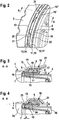
- a pneumatic brake booster 1 has a thin-walled booster housing 2.
- the booster housing 2 comprises shell elements 3 and 4, which are connected to one another in their radial outer area.
- the boosting force is generated in the pneumatic brake booster 1 by the pressure difference between a vacuum chamber 25 and a working chamber 26.
- the vacuum chamber 25 is pneumatically separated from the working chamber 26 by an elastomeric sealing element 5, which is moved axially in the booster housing 2 during operation. To compensate for the movement of the sealing element 5, it has a rolling diaphragm section 7, on which a circumferential sealing bead 6 is formed on its radial outer edge.
- the sealing bead 6 serves on the one hand to seal the interior of the amplifier housing 2 from the environment, and on the other hand to fasten the sealing element 5 to the amplifier housing 2.
- the sealing bead 6 is clamped in a clamping space 8 between the shell elements 3 and 4 in a pneumatically sealing manner.
- the clamping space 8 is created when the two shell elements 3 and 4 are placed against one another through their separate shaping produced by forming technology and is delimited by walls 9,10,11,12, on their nature below, in particular in the Fig. 3 is received.
- each form-fit section 18 a form fit is formed between the shell elements 3 and 4 in that a nose 19 is positioned in a corresponding recess 20.
- the form fit acts both in the circumferential direction and axially in the direction of the two shell elements 3 and 4 with respect to one another.
- the nose 19 is formed on a circumferential collar 17 which is formed on the shell element 4 and protrudes radially outward.
- the recess (20) is arranged in a tubular projection 14 which extends axially from a radial circumferential shoulder 13 on the shell element 3 essentially in the direction of the shell element 4.
- nose 19 and recess 20 are also permissible within the invention.
- the form-fit sections 18, 18 ', 18 ", ... can be distributed within the invention both regularly and irregularly on the circumference of the shell elements 3 and 4. With an irregular circumference distribution, a defined rotational position of the two shell elements 3 and 4 with respect to one another can be particularly simple coded and clearly produced without errors.
- axially pre-stretched flexible tabs 21 are provided on the projection 14. After the shell elements 3 and 4 have been joined together, the bending tabs 21 are folded over or bent around the radial outer edge 22 of the collar 17. In this case, the bending angle can be significantly less than 90 ° and possibly even less than 45 ° for operationally reliable fixation, so that tearing of a superficial anti-corrosion layer can be avoided.
- Fig. 3 is the structure of the terminal space 8 according to the embodiment Fig. 1 shown enlarged in a sectional view.
- the clamping space 8 is essentially delimited by four walls 9, 10, 11, 12, which in turn are formed by shaped elements of the shell elements 3 and 4.
- An end wall 9 of the clamping space 8 on the rolling diaphragm side is formed by a circumferential radial shoulder 13 of the shell element 3.
- a radial outer wall 10 is formed by a tubular projection 14 which extends from the shoulder 13 essentially in the axial direction and on which the bending tabs 21 are formed.
- a radial inner wall 11 is formed by a tubular, axially pre-stretched axial projection 15 of the second shell element 4.
- the projection 15 is designed to be folded at its front edge 16, so that the front edge 16 is rounded and the projection 15 has twice the wall thickness of the shell element 4.
- a bead-side rear wall 12 of the clamping space 8 is formed by a circumferential, radially outwardly projecting collar 17 which is formed on the second half-shell 4 and directly adjoins the projection 15.
- the rolling diaphragm section 7 is pulled by the pressure difference in the direction of the vacuum chamber 25, as a result of which the sealing bead 6 tends to slide out of the clamping space 8 into the interior of the booster housing 2.
- the rolling diaphragm section 7 is guided through a narrow annular gap 24, the radial gap dimension b of which is significantly narrower than the thickness of the sealing bead 6.
- the annular gap 24 is not parallel in cross-section, but approximately conical and spreads in the direction of the clamping space 8. In the embodiment shown, this is achieved by a wall area 23 of the shell element 3 directly in front of the shoulder 13 being essentially conical or is designed conical with the cone angle ⁇ > 1 °.
- the axial extension a of the annular gap 24 should be at least equal to and preferably at least twice as large as its radial gap dimension b measured at or before its confluence with the clamping space 8 or before the rounding at the transition to the shoulder 13.
- Such a conical or funnel-shaped cross-sectional profile of the annular gap 24 prevents the sealing element from being damaged during operation at the transition from the rolling diaphragm section 7 to the sealing bead 6, for example, because the load from the rolling diaphragm section 7 spreads more evenly over a larger volume of the sealing bead 6, on the other hand, the sealing bead 6 is prevented from being partially drawn into the annular gap 24 at particularly high loads on the rolling diaphragm section 7 and from remaining jammed there, because the present inclined wall geometry promotes the build-up of axially directed components of reaction forces when the sealing bead 6 is compressed and thus supports their decompression in the direction of the clamping chamber 8 after the load has dropped.
Landscapes
- Engineering & Computer Science (AREA)
- Transportation (AREA)
- Mechanical Engineering (AREA)
- Braking Systems And Boosters (AREA)
Description
- Die Erfindung betrifft einen pneumatischen Bremskraftverstärker insbesondere für eine hydraulische Kraftfahrzeugbremsanlage mit Merkmalen nach dem Oberbegriff des Anspruchs 1.
- Derartige Bremskraftverstärker sind weit verbreitet und bekannt. Das Verstärkergehäuse von einem derartigen Bremskraftverstärkerweise weist wenigstens zwei dünnwandige Schalenelemente auf, welche miteinander verbunden oder aneinander fixiert beziehungsweise gekoppelt sind. In dem Verstärkergehäuse ist dabei wenigstens eine Unterdruckkammer von einer Arbeitskammer durch ein Abdichtelement aus Elastomerwerkstoff pneumatisch getrennt. Weil das Abdichtelement im Betrieb axial über längere Strecken verfahren wird, verfügt es, meinst radial außen, über einen Rollmembranabschnitt, an dessen Radialen Außenrand eine Dichtwulst angeformt ist. Diese Dichtwulst wird zwischen den Schalenelementen des Verstärkergehäuses in einem Dichtsitz - einer Art Klemmraum eingeklemmt, dessen Wände durch eine gesonderte Formgebung der Schalenelemente gebildet werden.
- Für eine dauerhaft zuverlässige Abdichtung muss beispielsweise vorgesorgt werden, dass der sich bewegende Rollmembranabschnitt weder bei Montage noch im Betrieb an scharfen Kanten beschädigt wird, dass ein Herausrutschen der Dichtwulst im betrieb - sogenanntes Ausknöpfen - verhindert wird und die Schalenelemente zugleich möglichst einfach und sicher herstellbar und miteinander verbindbar sind. Zudem ist ein dauerhafter Korrosionsschutz von großer Bedeutung.
- Aus
JP 2013252787 A - Aus
US 7 048 342 B1 ist ein Bremskraftverstärker bekannt, bei dem die Verbindung der Schalenelemente durch Biegelaschen realisiert sind, welche an dem rückseitigen Schalenelement ausgebildet sind. Nach dem Zusammenführen der beiden Schalenelemente werden die Biegelaschen axial hinter einem radial gerichteten Kragen des zweiten Schalenelements nach radial innen umgebogen, wodurch ein Auseinanderschieben der beiden Schalenelemente verhindert wird. Hierdurch können jedoch weder eine definierte Positionierung der beiden Schalenelemente zueinander noch der Klemmgrad des Dichtwulstes exakt festgelegt werden, was den nachfolgenden Kalibrierungsaufwand signifikant erhöht. - Es stellt sich somit die Aufgabe, einen herstell- und montageoptimierten Bremskraftverstärker anzubieten, bei dem das Abdichtelement sicher und dauerhaft zuverlässig aufgenommen werden kann.
- Die Aufgabe wird erfindungsgemäß durch einen Bremskraftverstärker mit der Merkmalskombination nach dem Anspruch 1 gelöst. Unteransprüche zusammen mit Figuren und Beschreibungen geben weitere erfindungsgemäße Ausführungsformen und vorteilhafte Weiterbildungen an.
- Im Folgenden werden die Einzelheiten und Vorteile der Erfindung anhand Figurenbeschreibungen näher erläutert. Dabei wird auf die Beschreibung von allgemein bekannten Aspekten und Funktionen eines gattungsgemäßen Bremskraftverstärkers weitestgehend verzichtet und lediglich auf die erfindungsrelevanten Details eingegangen.
- Im Einzelnen zeigt die
-
Fig.1 beispielhaft eine Axialschnittdarstellung einer Ausführungsform des erfindungsgemäßen Bremskraftverstärkers. -
Fig.2 Teilansicht von zwei noch nicht miteinander verbundenen Schalenelementen in räumlicher Explosionsdarstellung. -
Fig.3 eine vergrößerte Schnittansicht des Klemmraums gemäß Ausführung nachFig.1 mit einer noch nicht umgelegten Biegelasche. -
Fig.4 eine vergrößerte Schnittansicht des Klemmraums gemäß Ausführung nachFig.1 nach der Endmontage, mit einer umgelegten Biegelasche. - Ein pneumatischer Bremskraftverstärker 1 verfügt über ein dünnwandiges Verstärkergehäuse 2. Das Verstärkergehäuse 2 umfasst Schalenelemente 3 und 4, die in ihrem radialen Außenbereich miteinander verbunden sind.
- Die Verstärkungskraft wird im pneumatischen Bremskraftverstärker 1 durch die Druckdifferenz zwischen einer Unterdruckkammer 25 und einer Arbeitskammer 26 erzeugt.
- Die Unterdruckkammer 25 ist von der Arbeitskammer 26 durch ein elastomeres Abdichtelement 5 pneumatisch abgegrenzt, welches beim Betrieb in dem Verstärkergehäuse 2 axial verfahren wird. Zur Ausgleich der Bewegung des Abdichtelements 5 verfügt dieses über einen Rollmembranabschnitt 7, an dem an seiner radialen Außenrand eine umlaufende Dichtwulst 6 angeformt ist.
- Die Dichtwulst 6 dient zum einem der Abdichtung des Innenraums des Verstärkergehäuses 2 gegen die Umgebung, zum anderen der Befestigung des Abdichtelements 5 am Verstärkergehäuse 2. Die Dichtwulst 6 ist in einem Klemmraum 8 zwischen den Schalenelementen 3 und 4 pneumatisch dichtend eingeklemmt. Der Klemmraum 8 entsteht beim Aneinanderlegen der beiden Schalenelemente 3 und 4 durch deren gesonderte, umformtechnisch erzeugte Formgebung und wird durch Wände 9,10,11,12 begrenzt, auf deren Beschaffenheit nachfolgend, insbesondere in der
Fig.3 eingegangen wird. - Um eine eindeutige definierte Stellung der Schalenelemente 3 und 4 für den Zusammenbau zuverlässig festzulegen, sind an Schalenelementen 3 und 4 mehrere am Umfang verteilt angeordneten Formschlussabschnitte 18 vorgesehen.
- In jedem Formschlussabschnitt 18 wird zwischen dem Schalenelemente 3 und 4 ein Formschluss gebildet, indem eine Nase 19 in einer korrespondierenden Aussparung 20 positioniert wird. Dadurch wirkt der Formschluss zugleich sowohl in Umfangsrichtung, als auch axial in Richtung der beiden Schalenelemente 3 und 4 zueinander.
- In dem gezeigten Ausführungsbeispiel ist die Nase 19 an einem, an dem Schalenelement 4 ausgeformten, radial nach außen ragenden umlaufenden Kragen 17 ausgebildet.
- Die Aussparung (20) ist in einem rohrförmigen Vorsprung 14 angeordnet, welcher sich von einem radialen umlaufenden Absatz 13 am Schalenelement 3 axial im Wesentlichen in Richtung Schalenelement 4 erstreckt.
- Eine umgekehrte oder wechselnde Anordnung von Nase 19 und Aussparung 20 sind innerhalb der Erfindung ebenso zulässig.
- Die Formschlussabschnitte 18,18′,18",... können innerhalb der Erfindung sowohl regelmäßig als auch unregelmäßig am Umfang der Schalenelemente 3 und 4 verteilt angeordnet werden. Bei einer unregelmäßigen Umfangsverteilung kann eine definierte Verdrehlage der beiden Schalenelemente 3 und 4 zueinander besonders einfach kodiert und fehlerfrei eindeutig hergestellt werden.
- Um die Schalenelemente 3 und 4 möglichst einfach aneinander zu fixieren und dabei eine gegebenenfalls vorhandene oberflächliche Korrosionsschutzschicht nicht zu beschädigen, sind am Vorsprung 14 axial vorgestreckt ausgebildeten Biegelaschen 21 vorgesehen. Die Biegelaschen 21 werden nach dem Zusammenfügen der Schalenelemente 3 und 4 um die radiale Außenkante 22 des Kragens 17 umgelegt beziehungsweise gebogen. Der Biegewinkel kann dabei für eine betriebssichere Fixierung deutlich geringer als 90° und gegebenenfalls sogar weniger als 45° betragen, womit ein Reißen einer oberflächlichen Korrosionsschutzschicht vermieden werden kann.
- In der
Fig.3 wird der Aufbau des Klemmraums 8 gemäß der Ausführungsform nachFig.1 in einer Schnittdarstellung vergrößert dargestellt. - Der Klemmraum 8 wird im Wesentlichen durch vier Wände 9,10,11,12 begrenzt, die ihrerseits durch Formelemente der Schalenelemente 3 und 4 gebildet sind.
- Eine rollmembranseitige Stirnwand 9 des Klemmraums 8 ist durch einen umlaufenden radialen Absatz 13 des Schalenelements 3 gebildet.
- Eine radiale Außenwand 10 ist durch einen rohrförmigen Vorsprung 14 gebildet, der sich von dem Absatz 13 im Wesentlichen in axiale Richtung erstreckt und an dem im Übrigen dir Biegelaschen 21 angeformt sind.
- Eine radiale Innenwand 11 ist durch einen rohrförmigen, axial vorgestreckten axialen Vorsprung 15 des zweiten Schalenelements 4 gebildet. Der Vorsprung 15 ist an seiner Vorderkante 16 gefaltet gestaltet, so dass die Vorderkante 16 verrundet ist und der Vorsprung 15 eine doppelte Wandstärke des Schalenelements 4 aufweist.
- Eine wulstseitige Rückwand 12 des Klemmraums 8 ist durch einen umlaufenden, radial nach außen ragenden Kragen 17 gebildet, der an der zweiten Halbschale 4 ausgeformt ist und unmittelbar an den Vorsprung 15 anschließt.
- Im Verstärkerbetrieb wird der Rollmembranabschnitt 7 durch die Druckdifferenz in Richtung Unterdruckkammer 25 gezogen, wodurch die Dichtwulst 6 sich aus dem Klemmraum 8 in das Innere des Verstärkergehäuses 2 herauszurutschen bestrebt ist.
- Um ein Herausrutschen des Dichtwulstes 6 zu verhindern ist der Rollmembranabschnitt 7 durch einen schmalen Ringspalt 24 geführt, dessen radialer Spaltmaß b deutlich schmaler als die Dicke des Dichtwulstes 6 ist.
- In der abgebildeten, bevorzugten Ausführung ist der Ringspalt 24 im Querschnitt nichtparallel, sondern annähernd konisch ausgebildet und verbreitet sich in Richtung Klemmraum 8. In der gezeigten Ausführung wird dies erreicht, indem ein dem Absatz 13 unmittelbar vorgelagerter Wandungsbereich 23 des Schalenelements 3 im Wesentlichen konisch beziehungsweise kegelig mit dem Kegelwinkel α > 1° gestaltet ist.
- Zudem sollte die axiale Streckung a des Ringspaltes 24 mindestens gleich und bevorzugt mindestens doppelt so groß wie sein radiales Spaltmaß b an beziehungsweise vor seiner Einmündung in den Klemmraum 8 beziehungsweise vor der Verrundung am Übergang zum Absatz 13 gemessen.
- Durch ein derartiges kegeliges beziehungsweise trichterförmiges Querschnittsprofil des Ringspaltes 24 wird zum einen verhindert, dass das Abdichtelement am Übergang vom Rollmembranabschnitt 7 in die Dichtwulst 6 im Betrieb beschädigt, beispielsweise angerissen wird, weil die Last aus dem Rollmembranabschnitt 7 sich gleichmäßiger über ein größeres Volumen des Dichtwulstes 6 verteilen kann, Zum anderen wird verhindert, dass die Dichtwulst 6 bei besonders hohen Lasten am Rollmembranabschnitt 7 in den Ringspalt 24 teilweise eingezogen und dort klemmen bleibt, denn die vorliegende schräge Wandgeometrie fördert den Aufbau von axial gerichteten Anteilen von Reaktionskräften bei Kompression des Dichtwulstes 6 und unterstütz somit ihre Dekompression in Richtung Klemmkammer 8 nach Lastabfall.
-
- 1
- Bremskraftverstärker
- 2
- Verstärkergehäuse
- 3
- Gehäuseschale
- 4
- Gehäuseschale
- 5
- Abdichtelement
- 6
- Dichtwulst
- 7
- Rollmembranabschnitt
- 8
- Klemmraum
- 9
- Stirnwand
- 10
- Außenwand
- 11
- Innenwand
- 12
- Rückwand
- 13
- Absatz
- 14
- Vorsprung
- 15
- Vorsprung
- 16
- Vorderkante
- 17
- Kragen
- 18
- Formschlussabschnitt
- 19
- Nase
- 20
- Aussparung
- 21
- Biegelasche
- 22
- Außenkante
- 23
- Wandungsbereich
- 24
- Ringspalt
- 25
- Unterdruckkammer
- 26
- Arbeitskammer
- a
- axiale Streckung
- b
- radiales Spaltmaß
- α
- Kegelwinkel
Claims (9)
- Pneumatischer Bremskraftverstärker (1) mit einem Verstärkergehäuse (2), wobei das Verstärkergehäuse (2) wenigstens zwei dünnwandige Schalenelemente (3,4) und ein elastomeres Abdichtelement (5) aufweist, wobei das Abdichtelement (5) eine radial außen umlaufend ausgebildete Dichtwulst (6) und wenigstens einen an die Dichtwulst (6) anschließenden Rollmembranabschnitt (7) aufweist und die Dichtwulst (6) in einem Klemmraum (8) zwischen den Schalenelementen (3,4) pneumatisch dichtend eingeklemmt ist, wobei der Klemmraum (8) durch Wände (9, 10, 11, 12) gebildet ist, die in den Schalenelementen (3,4) umformtechnisch erzeugt sind, wobei• eine rollmembranseitige Stirnwand (9) des Klemmraums (8) durch einen umlaufenden radialen Absatz (13) eines ersten Schalenelements (3) gebildet ist,• eine radiale Außenwand (10) durch einen rohrförmigen Vorsprung (14) gebildet ist, der sich von dem Absatz (13) im Wesentlichen in axiale Richtung erstreckt,• eine radiale Innenwand (11) durch einen rohrförmigen, axial vorgestreckten und an seiner Vorderkante (16) gefalteten Vorsprung (15) eines zweiten Schalenelements (4) gebildet ist, eine wulstseitige Rückwand (12) des Klemmraums (8) durch einen umlaufenden, radial nach außen ragenden Kragen (17) gebildet ist, welcher an dem zweiten Schalenelement (4) ausgeformt ist, dadurch gekennzeichnet, dass zwischen der Rückwand (12) und der Außenwand (10) des Klemmraums (8) wenigstens ein Formschlussabschnitt (18) vorgesehen ist, welcher in Umfangsrichtung sowie axial in Richtung Dichtwulst (6) wirkt.
- Bremskraftverstärker (1) nach Anspruch 1, dadurch gekennzeichnet, dass der Formschluss im Formschlussabschnitt (18) durch wenigstens eine Nase (19) an einem der Schalenelemente (3 oder 4) gebildet ist, die in eine korrespondierende Aussparung (20) in dem anderen Schalenelement (4 oder 3) eingreift.
- Bremskraftverstärker (1) nach Anspruch 2, dadurch gekennzeichnet, dass die Nase (19) am Kragen (17) und die Aussparung (20) am Vorsprung (14) ausgebildet sind.
- Bremskraftverstärker (1) nach wenigstens einem der vorstehenden Ansprüche, dadurch gekennzeichnet, dass mehrere Formschlussabschnitte (18,18′,18",...) am Umfang der Schalenelemente (3,4) verteilt angeordnet sind.
- Bremskraftverstärker (1) nach Anspruch 4, dadurch gekennzeichnet, dass die Formschlussabschnitte (18,18′,18",...) unregelmäßig am Umfang der Schalenelemente (3,4) verteilt angeordnet sind.
- Bremskraftverstärker (1) nach wenigstens einem der vorstehenden Ansprüche, dadurch gekennzeichnet, dass die Schalenelemente (3,4) durch Biegelaschen (21) aneinander fixiert sind, wobei die Biegelaschen (21) am Vorsprung (14) axial vorgestreckt ausgebildet und um eine radiale Außenkante (22) des Kragens (17) gebogen sind.
- Bremskraftverstärker (1) nach wenigstens einem der vorstehenden Ansprüche, dadurch gekennzeichnet, dass zwischen dem Vorsprung (15) und einem Wandungsbereich (23) des Schalenelements (3), der sich axial an den Absatz (13) anschließt, ein Ringspalt (24) angeordnet ist durch welchen ein Bereich des Rollmembranabschnitts (7) verläuft, wobei der Wandungsbereich (23) im Bereich des Ringspaltes (24) kegelig ausgebildet ist.
- Bremskraftverstärker (1) nach Anspruch 7, dadurch gekennzeichnet, dass eine axiale Streckung (a) des Ringspaltes (24) mindestens genauso groß ist wie sein radiales Spaltmaß (b) an der Einmündung in den Klemmraum (8).
- Bremskraftverstärker (1) nach Anspruch 7, dadurch gekennzeichnet, dass eine axiale Streckung (a) des Ringspaltes (24) mindestens doppelt so groß ist wie sein radiales Spaltmaß (b) an der Einmündung in den Klemmraum (8).
Applications Claiming Priority (2)
| Application Number | Priority Date | Filing Date | Title |
|---|---|---|---|
| DE102016224490.6A DE102016224490A1 (de) | 2016-12-08 | 2016-12-08 | Pneumatischer Bremskraftverstärker mit einem Abdichtelement |
| PCT/EP2017/079591 WO2018104031A1 (de) | 2016-12-08 | 2017-11-17 | Pneumatischer bremskraftverstärker mit einem abdichtelement |
Publications (2)
| Publication Number | Publication Date |
|---|---|
| EP3551515A1 EP3551515A1 (de) | 2019-10-16 |
| EP3551515B1 true EP3551515B1 (de) | 2021-10-06 |
Family
ID=60413195
Family Applications (1)
| Application Number | Title | Priority Date | Filing Date |
|---|---|---|---|
| EP17801439.5A Active EP3551515B1 (de) | 2016-12-08 | 2017-11-17 | Pneumatischer bremskraftverstärker mit einem abdichtelement |
Country Status (6)
| Country | Link |
|---|---|
| US (1) | US11148650B2 (de) |
| EP (1) | EP3551515B1 (de) |
| KR (1) | KR102230627B1 (de) |
| CN (1) | CN110049907B (de) |
| DE (1) | DE102016224490A1 (de) |
| WO (1) | WO2018104031A1 (de) |
Family Cites Families (21)
| Publication number | Priority date | Publication date | Assignee | Title |
|---|---|---|---|---|
| DE3031206A1 (de) | 1980-08-19 | 1982-04-01 | Alfred Teves Gmbh, 6000 Frankfurt | Unterdruckgehaeuse fuer einen bremskraftverstaerker |
| GB2112105B (en) | 1981-11-18 | 1985-09-11 | Aisin Seiki | Closing brake booster housing |
| JPS60157361U (ja) | 1984-03-23 | 1985-10-19 | アイシン精機株式会社 | タンデム型倍力装置 |
| JPH0437012Y2 (de) * | 1989-08-08 | 1992-09-01 | ||
| DE3942211A1 (de) | 1989-12-21 | 1991-06-27 | Teves Gmbh Alfred | Gehaeuse fuer einen pneumatischen kraftverstaerker und verfahren zu dessen herstellung |
| JP3489277B2 (ja) * | 1995-07-17 | 2004-01-19 | トヨタ自動車株式会社 | 車両用制動装置 |
| JPH09207759A (ja) | 1996-01-31 | 1997-08-12 | Aisin Seiki Co Ltd | タンデム型負圧式倍力装置 |
| GB2328991B (en) | 1997-09-04 | 2001-07-11 | Gen Motors Corp | Brake booster |
| US6003425A (en) * | 1998-03-27 | 1999-12-21 | Jidosha Kiki Co., Ltd. | Booster |
| US6390567B1 (en) * | 2001-08-20 | 2002-05-21 | Robert Bosch Corporation | Housing for a brake booster |
| DE10334457A1 (de) * | 2003-07-29 | 2005-02-17 | Continental Teves Ag & Co. Ohg | Bremskraftverstärker |
| US6895853B1 (en) | 2003-10-30 | 2005-05-24 | Robert Bosch Corporation | Tandem brake booster |
| JP4273931B2 (ja) | 2003-11-04 | 2009-06-03 | 株式会社アドヴィックス | 負圧式倍力装置 |
| US7048342B1 (en) | 2004-01-27 | 2006-05-23 | Robert Bosch Corporation | Housing for a brake booster |
| DE102006011414A1 (de) | 2005-05-11 | 2006-11-23 | Continental Teves Ag & Co. Ohg | Pneumatischer Bremskraftverstärker |
| DE102005061353A1 (de) | 2005-07-22 | 2007-01-25 | Continental Teves Ag & Co. Ohg | Pneumatischer Bremskraftverstärker |
| JP5321803B2 (ja) | 2008-11-28 | 2013-10-23 | 日立オートモティブシステムズ株式会社 | 気圧式倍力装置 |
| CN201553139U (zh) | 2009-11-06 | 2010-08-18 | 温州市东启汽车零部件制造有限公司 | 带电磁阀真空助力器 |
| DE102012208866A1 (de) * | 2011-05-27 | 2012-11-29 | Continental Teves Ag & Co. Ohg | Pneumatischer Bremskraftverstärker mit einer Sensorvorrichtung zur berührungslosen Überwachung von Position und Bewegung einer beweglichen Wand |
| JP5749686B2 (ja) | 2012-06-07 | 2015-07-15 | 日信工業株式会社 | 車両用負圧センサ付き負圧ブースタ |
| FR3021937B1 (fr) | 2014-06-06 | 2017-11-10 | Bosch Gmbh Robert | Servofrein a depression |
-
2016
- 2016-12-08 DE DE102016224490.6A patent/DE102016224490A1/de not_active Withdrawn
-
2017
- 2017-11-17 CN CN201780075002.9A patent/CN110049907B/zh active Active
- 2017-11-17 KR KR1020197016131A patent/KR102230627B1/ko active Active
- 2017-11-17 WO PCT/EP2017/079591 patent/WO2018104031A1/de not_active Ceased
- 2017-11-17 US US16/463,015 patent/US11148650B2/en active Active
- 2017-11-17 EP EP17801439.5A patent/EP3551515B1/de active Active
Also Published As
| Publication number | Publication date |
|---|---|
| WO2018104031A1 (de) | 2018-06-14 |
| US20190322260A1 (en) | 2019-10-24 |
| KR20190077505A (ko) | 2019-07-03 |
| KR102230627B1 (ko) | 2021-03-19 |
| US11148650B2 (en) | 2021-10-19 |
| CN110049907B (zh) | 2022-05-17 |
| CN110049907A (zh) | 2019-07-23 |
| DE102016224490A1 (de) | 2018-06-14 |
| EP3551515A1 (de) | 2019-10-16 |
Similar Documents
| Publication | Publication Date | Title |
|---|---|---|
| EP0465896B1 (de) | Verbindungselement für Wellrohre und Schläuche | |
| EP2762761B1 (de) | Abgasrohr sowie Abgasrohrsystem | |
| EP2082101B1 (de) | Rinne | |
| EP2044359A1 (de) | Hülse und kombination von hülse mit presswerkzeug | |
| EP3172465B1 (de) | Drehbare axial sichernde und druckfeste leitungsverbindung | |
| DE102014101795A1 (de) | Quetschverbindung mit entgegengesetzt gerichteten Zacken | |
| EP2278204B1 (de) | Wellrohranschlussverschraubung | |
| EP1175323B1 (de) | Pneumatischer bremskraftverstärker | |
| DE10347927B4 (de) | Verfahren und Vorrichtung zur Herstellung einer Rohrpressverbindung an einer Steckverbindung | |
| DE19740649B4 (de) | Steckverbindung für den Anschluß von Rohr- und Schlauchleitungen | |
| EP2019246A2 (de) | Anordnung zur Befestigung einer Leitung mit einem profilierten Aussendurchmesser und Montageverfahren | |
| EP3199772B1 (de) | Schalldämpfer für eine abgasanlage | |
| EP3551515B1 (de) | Pneumatischer bremskraftverstärker mit einem abdichtelement | |
| EP0405245A2 (de) | Schlauchanschlussarmatur für einen Hochdruckschlauch | |
| DE102017210844A1 (de) | Presshülse | |
| EP2196716B1 (de) | Schlauchkupplung | |
| CH701049B1 (de) | Spannschelle für Rohr- oder Schlauchverbindungen. | |
| DE102004016051B4 (de) | Bremskraftverstärker | |
| EP2038573B1 (de) | Rohrverbindung | |
| EP3313699A1 (de) | Pneumatischer bremskraftverstärker mit einem verbindungsbolzen | |
| DE102014217410A1 (de) | Fluidleitende Verbindungsanordnung sowie Klemmring | |
| DE102004050852B4 (de) | Rohrverbindung | |
| DE102005028564A1 (de) | Schlauchrollbalgluftfeder | |
| EP1611387B1 (de) | Rohrkupplung | |
| EP1722145B1 (de) | Rohrelement mit Schutzelement |
Legal Events
| Date | Code | Title | Description |
|---|---|---|---|
| STAA | Information on the status of an ep patent application or granted ep patent |
Free format text: STATUS: UNKNOWN |
|
| STAA | Information on the status of an ep patent application or granted ep patent |
Free format text: STATUS: THE INTERNATIONAL PUBLICATION HAS BEEN MADE |
|
| PUAI | Public reference made under article 153(3) epc to a published international application that has entered the european phase |
Free format text: ORIGINAL CODE: 0009012 |
|
| STAA | Information on the status of an ep patent application or granted ep patent |
Free format text: STATUS: REQUEST FOR EXAMINATION WAS MADE |
|
| 17P | Request for examination filed |
Effective date: 20190708 |
|
| AK | Designated contracting states |
Kind code of ref document: A1 Designated state(s): AL AT BE BG CH CY CZ DE DK EE ES FI FR GB GR HR HU IE IS IT LI LT LU LV MC MK MT NL NO PL PT RO RS SE SI SK SM TR |
|
| AX | Request for extension of the european patent |
Extension state: BA ME |
|
| DAV | Request for validation of the european patent (deleted) | ||
| DAX | Request for extension of the european patent (deleted) | ||
| GRAP | Despatch of communication of intention to grant a patent |
Free format text: ORIGINAL CODE: EPIDOSNIGR1 |
|
| STAA | Information on the status of an ep patent application or granted ep patent |
Free format text: STATUS: GRANT OF PATENT IS INTENDED |
|
| INTG | Intention to grant announced |
Effective date: 20210527 |
|
| GRAS | Grant fee paid |
Free format text: ORIGINAL CODE: EPIDOSNIGR3 |
|
| GRAA | (expected) grant |
Free format text: ORIGINAL CODE: 0009210 |
|
| STAA | Information on the status of an ep patent application or granted ep patent |
Free format text: STATUS: THE PATENT HAS BEEN GRANTED |
|
| AK | Designated contracting states |
Kind code of ref document: B1 Designated state(s): AL AT BE BG CH CY CZ DE DK EE ES FI FR GB GR HR HU IE IS IT LI LT LU LV MC MK MT NL NO PL PT RO RS SE SI SK SM TR |
|
| REG | Reference to a national code |
Ref country code: GB Ref legal event code: FG4D Free format text: NOT ENGLISH |
|
| REG | Reference to a national code |
Ref country code: CH Ref legal event code: EP Ref country code: AT Ref legal event code: REF Ref document number: 1435965 Country of ref document: AT Kind code of ref document: T Effective date: 20211015 |
|
| REG | Reference to a national code |
Ref country code: IE Ref legal event code: FG4D Free format text: LANGUAGE OF EP DOCUMENT: GERMAN |
|
| REG | Reference to a national code |
Ref country code: DE Ref legal event code: R096 Ref document number: 502017011689 Country of ref document: DE |
|
| REG | Reference to a national code |
Ref country code: LT Ref legal event code: MG9D |
|
| REG | Reference to a national code |
Ref country code: NL Ref legal event code: MP Effective date: 20211006 |
|
| PG25 | Lapsed in a contracting state [announced via postgrant information from national office to epo] |
Ref country code: RS Free format text: LAPSE BECAUSE OF FAILURE TO SUBMIT A TRANSLATION OF THE DESCRIPTION OR TO PAY THE FEE WITHIN THE PRESCRIBED TIME-LIMIT Effective date: 20211006 Ref country code: LT Free format text: LAPSE BECAUSE OF FAILURE TO SUBMIT A TRANSLATION OF THE DESCRIPTION OR TO PAY THE FEE WITHIN THE PRESCRIBED TIME-LIMIT Effective date: 20211006 Ref country code: FI Free format text: LAPSE BECAUSE OF FAILURE TO SUBMIT A TRANSLATION OF THE DESCRIPTION OR TO PAY THE FEE WITHIN THE PRESCRIBED TIME-LIMIT Effective date: 20211006 Ref country code: BG Free format text: LAPSE BECAUSE OF FAILURE TO SUBMIT A TRANSLATION OF THE DESCRIPTION OR TO PAY THE FEE WITHIN THE PRESCRIBED TIME-LIMIT Effective date: 20220106 |
|
| PG25 | Lapsed in a contracting state [announced via postgrant information from national office to epo] |
Ref country code: IS Free format text: LAPSE BECAUSE OF FAILURE TO SUBMIT A TRANSLATION OF THE DESCRIPTION OR TO PAY THE FEE WITHIN THE PRESCRIBED TIME-LIMIT Effective date: 20220206 Ref country code: SE Free format text: LAPSE BECAUSE OF FAILURE TO SUBMIT A TRANSLATION OF THE DESCRIPTION OR TO PAY THE FEE WITHIN THE PRESCRIBED TIME-LIMIT Effective date: 20211006 Ref country code: PT Free format text: LAPSE BECAUSE OF FAILURE TO SUBMIT A TRANSLATION OF THE DESCRIPTION OR TO PAY THE FEE WITHIN THE PRESCRIBED TIME-LIMIT Effective date: 20220207 Ref country code: PL Free format text: LAPSE BECAUSE OF FAILURE TO SUBMIT A TRANSLATION OF THE DESCRIPTION OR TO PAY THE FEE WITHIN THE PRESCRIBED TIME-LIMIT Effective date: 20211006 Ref country code: NO Free format text: LAPSE BECAUSE OF FAILURE TO SUBMIT A TRANSLATION OF THE DESCRIPTION OR TO PAY THE FEE WITHIN THE PRESCRIBED TIME-LIMIT Effective date: 20220106 Ref country code: NL Free format text: LAPSE BECAUSE OF FAILURE TO SUBMIT A TRANSLATION OF THE DESCRIPTION OR TO PAY THE FEE WITHIN THE PRESCRIBED TIME-LIMIT Effective date: 20211006 Ref country code: LV Free format text: LAPSE BECAUSE OF FAILURE TO SUBMIT A TRANSLATION OF THE DESCRIPTION OR TO PAY THE FEE WITHIN THE PRESCRIBED TIME-LIMIT Effective date: 20211006 Ref country code: HR Free format text: LAPSE BECAUSE OF FAILURE TO SUBMIT A TRANSLATION OF THE DESCRIPTION OR TO PAY THE FEE WITHIN THE PRESCRIBED TIME-LIMIT Effective date: 20211006 Ref country code: GR Free format text: LAPSE BECAUSE OF FAILURE TO SUBMIT A TRANSLATION OF THE DESCRIPTION OR TO PAY THE FEE WITHIN THE PRESCRIBED TIME-LIMIT Effective date: 20220107 Ref country code: ES Free format text: LAPSE BECAUSE OF FAILURE TO SUBMIT A TRANSLATION OF THE DESCRIPTION OR TO PAY THE FEE WITHIN THE PRESCRIBED TIME-LIMIT Effective date: 20211006 |
|
| REG | Reference to a national code |
Ref country code: DE Ref legal event code: R097 Ref document number: 502017011689 Country of ref document: DE |
|
| REG | Reference to a national code |
Ref country code: CH Ref legal event code: PL |
|
| PG25 | Lapsed in a contracting state [announced via postgrant information from national office to epo] |
Ref country code: SM Free format text: LAPSE BECAUSE OF FAILURE TO SUBMIT A TRANSLATION OF THE DESCRIPTION OR TO PAY THE FEE WITHIN THE PRESCRIBED TIME-LIMIT Effective date: 20211006 Ref country code: SK Free format text: LAPSE BECAUSE OF FAILURE TO SUBMIT A TRANSLATION OF THE DESCRIPTION OR TO PAY THE FEE WITHIN THE PRESCRIBED TIME-LIMIT Effective date: 20211006 Ref country code: RO Free format text: LAPSE BECAUSE OF FAILURE TO SUBMIT A TRANSLATION OF THE DESCRIPTION OR TO PAY THE FEE WITHIN THE PRESCRIBED TIME-LIMIT Effective date: 20211006 Ref country code: MC Free format text: LAPSE BECAUSE OF FAILURE TO SUBMIT A TRANSLATION OF THE DESCRIPTION OR TO PAY THE FEE WITHIN THE PRESCRIBED TIME-LIMIT Effective date: 20211006 Ref country code: LU Free format text: LAPSE BECAUSE OF NON-PAYMENT OF DUE FEES Effective date: 20211117 Ref country code: EE Free format text: LAPSE BECAUSE OF FAILURE TO SUBMIT A TRANSLATION OF THE DESCRIPTION OR TO PAY THE FEE WITHIN THE PRESCRIBED TIME-LIMIT Effective date: 20211006 Ref country code: DK Free format text: LAPSE BECAUSE OF FAILURE TO SUBMIT A TRANSLATION OF THE DESCRIPTION OR TO PAY THE FEE WITHIN THE PRESCRIBED TIME-LIMIT Effective date: 20211006 Ref country code: CZ Free format text: LAPSE BECAUSE OF FAILURE TO SUBMIT A TRANSLATION OF THE DESCRIPTION OR TO PAY THE FEE WITHIN THE PRESCRIBED TIME-LIMIT Effective date: 20211006 Ref country code: BE Free format text: LAPSE BECAUSE OF NON-PAYMENT OF DUE FEES Effective date: 20211130 |
|
| REG | Reference to a national code |
Ref country code: BE Ref legal event code: MM Effective date: 20211130 |
|
| PLBE | No opposition filed within time limit |
Free format text: ORIGINAL CODE: 0009261 |
|
| STAA | Information on the status of an ep patent application or granted ep patent |
Free format text: STATUS: NO OPPOSITION FILED WITHIN TIME LIMIT |
|
| 26N | No opposition filed |
Effective date: 20220707 |
|
| REG | Reference to a national code |
Ref country code: DE Ref legal event code: R081 Ref document number: 502017011689 Country of ref document: DE Owner name: CONTINENTAL AUTOMOTIVE TECHNOLOGIES GMBH, DE Free format text: FORMER OWNER: CONTINENTAL TEVES AG & CO. OHG, 60488 FRANKFURT, DE Ref country code: DE Ref legal event code: R081 Ref document number: 502017011689 Country of ref document: DE Owner name: AUMOVIO GERMANY GMBH, DE Free format text: FORMER OWNER: CONTINENTAL TEVES AG & CO. OHG, 60488 FRANKFURT, DE |
|
| GBPC | Gb: european patent ceased through non-payment of renewal fee |
Effective date: 20220106 |
|
| PG25 | Lapsed in a contracting state [announced via postgrant information from national office to epo] |
Ref country code: IE Free format text: LAPSE BECAUSE OF NON-PAYMENT OF DUE FEES Effective date: 20211117 Ref country code: GB Free format text: LAPSE BECAUSE OF NON-PAYMENT OF DUE FEES Effective date: 20220106 Ref country code: AL Free format text: LAPSE BECAUSE OF FAILURE TO SUBMIT A TRANSLATION OF THE DESCRIPTION OR TO PAY THE FEE WITHIN THE PRESCRIBED TIME-LIMIT Effective date: 20211006 |
|
| PG25 | Lapsed in a contracting state [announced via postgrant information from national office to epo] |
Ref country code: SI Free format text: LAPSE BECAUSE OF FAILURE TO SUBMIT A TRANSLATION OF THE DESCRIPTION OR TO PAY THE FEE WITHIN THE PRESCRIBED TIME-LIMIT Effective date: 20211006 Ref country code: FR Free format text: LAPSE BECAUSE OF NON-PAYMENT OF DUE FEES Effective date: 20211206 |
|
| PG25 | Lapsed in a contracting state [announced via postgrant information from national office to epo] |
Ref country code: IT Free format text: LAPSE BECAUSE OF FAILURE TO SUBMIT A TRANSLATION OF THE DESCRIPTION OR TO PAY THE FEE WITHIN THE PRESCRIBED TIME-LIMIT Effective date: 20211006 |
|
| PG25 | Lapsed in a contracting state [announced via postgrant information from national office to epo] |
Ref country code: CY Free format text: LAPSE BECAUSE OF FAILURE TO SUBMIT A TRANSLATION OF THE DESCRIPTION OR TO PAY THE FEE WITHIN THE PRESCRIBED TIME-LIMIT Effective date: 20211006 |
|
| PG25 | Lapsed in a contracting state [announced via postgrant information from national office to epo] |
Ref country code: LI Free format text: LAPSE BECAUSE OF NON-PAYMENT OF DUE FEES Effective date: 20220701 Ref country code: HU Free format text: LAPSE BECAUSE OF FAILURE TO SUBMIT A TRANSLATION OF THE DESCRIPTION OR TO PAY THE FEE WITHIN THE PRESCRIBED TIME-LIMIT; INVALID AB INITIO Effective date: 20171117 Ref country code: CH Free format text: LAPSE BECAUSE OF NON-PAYMENT OF DUE FEES Effective date: 20220701 |
|
| REG | Reference to a national code |
Ref country code: AT Ref legal event code: MM01 Ref document number: 1435965 Country of ref document: AT Kind code of ref document: T Effective date: 20221117 |
|
| PG25 | Lapsed in a contracting state [announced via postgrant information from national office to epo] |
Ref country code: AT Free format text: LAPSE BECAUSE OF NON-PAYMENT OF DUE FEES Effective date: 20221117 |
|
| REG | Reference to a national code |
Ref country code: DE Ref legal event code: R081 Ref document number: 502017011689 Country of ref document: DE Owner name: CONTINENTAL AUTOMOTIVE TECHNOLOGIES GMBH, DE Free format text: FORMER OWNER: CONTINENTAL AUTOMOTIVE TECHNOLOGIES GMBH, 30165 HANNOVER, DE Ref country code: DE Ref legal event code: R081 Ref document number: 502017011689 Country of ref document: DE Owner name: AUMOVIO GERMANY GMBH, DE Free format text: FORMER OWNER: CONTINENTAL AUTOMOTIVE TECHNOLOGIES GMBH, 30165 HANNOVER, DE |
|
| PG25 | Lapsed in a contracting state [announced via postgrant information from national office to epo] |
Ref country code: MK Free format text: LAPSE BECAUSE OF FAILURE TO SUBMIT A TRANSLATION OF THE DESCRIPTION OR TO PAY THE FEE WITHIN THE PRESCRIBED TIME-LIMIT Effective date: 20211006 |
|
| PG25 | Lapsed in a contracting state [announced via postgrant information from national office to epo] |
Ref country code: MT Free format text: LAPSE BECAUSE OF FAILURE TO SUBMIT A TRANSLATION OF THE DESCRIPTION OR TO PAY THE FEE WITHIN THE PRESCRIBED TIME-LIMIT Effective date: 20211006 |
|
| PG25 | Lapsed in a contracting state [announced via postgrant information from national office to epo] |
Ref country code: TR Free format text: LAPSE BECAUSE OF FAILURE TO SUBMIT A TRANSLATION OF THE DESCRIPTION OR TO PAY THE FEE WITHIN THE PRESCRIBED TIME-LIMIT Effective date: 20211006 |
|
| PGFP | Annual fee paid to national office [announced via postgrant information from national office to epo] |
Ref country code: DE Payment date: 20251130 Year of fee payment: 9 |
|
| REG | Reference to a national code |
Ref country code: DE Ref legal event code: R081 Ref document number: 502017011689 Country of ref document: DE Owner name: AUMOVIO GERMANY GMBH, DE Free format text: FORMER OWNER: CONTINENTAL AUTOMOTIVE TECHNOLOGIES GMBH, 30175 HANNOVER, DE |