EP3551499B1 - Remotely adjustable captive beam system - Google Patents
Remotely adjustable captive beam system Download PDFInfo
- Publication number
- EP3551499B1 EP3551499B1 EP19721507.2A EP19721507A EP3551499B1 EP 3551499 B1 EP3551499 B1 EP 3551499B1 EP 19721507 A EP19721507 A EP 19721507A EP 3551499 B1 EP3551499 B1 EP 3551499B1
- Authority
- EP
- European Patent Office
- Prior art keywords
- aperture
- bracket
- latch
- track
- rotating portion
- Prior art date
- Legal status (The legal status is an assumption and is not a legal conclusion. Google has not performed a legal analysis and makes no representation as to the accuracy of the status listed.)
- Active
Links
- 238000000034 method Methods 0.000 description 43
- 230000001154 acute effect Effects 0.000 description 7
- 230000000712 assembly Effects 0.000 description 6
- 238000000429 assembly Methods 0.000 description 6
- 230000005540 biological transmission Effects 0.000 description 6
- 238000005516 engineering process Methods 0.000 description 4
- 230000000284 resting effect Effects 0.000 description 3
- 239000011800 void material Substances 0.000 description 2
- 238000010276 construction Methods 0.000 description 1
- 238000012986 modification Methods 0.000 description 1
- 230000004048 modification Effects 0.000 description 1
- 230000008054 signal transmission Effects 0.000 description 1
Images


Classifications
-
- B—PERFORMING OPERATIONS; TRANSPORTING
- B60—VEHICLES IN GENERAL
- B60P—VEHICLES ADAPTED FOR LOAD TRANSPORTATION OR TO TRANSPORT, TO CARRY, OR TO COMPRISE SPECIAL LOADS OR OBJECTS
- B60P7/00—Securing or covering of load on vehicles
- B60P7/06—Securing of load
- B60P7/135—Securing or supporting by load bracing means
- B60P7/15—Securing or supporting by load bracing means the load bracing means comprising a movable bar
-
- B—PERFORMING OPERATIONS; TRANSPORTING
- B61—RAILWAYS
- B61D—BODY DETAILS OR KINDS OF RAILWAY VEHICLES
- B61D45/00—Means or devices for securing or supporting the cargo, including protection against shocks
- B61D45/001—Devices for fixing to walls or floors
Definitions
- Captive beam systems include decking beams with components that slide within vertical tracks fixed to opposite walls of a cargo compartment.
- the beam can be stowed close to the ceiling of the cargo compartment when not needed for use, and can be selectively lowered to a position for loading cargo or for shoring purposes.
- the ends of the beams slide within the track and include locking features that can selectively the ends of the beams with respect to the tracks at various heights along the track.
- the adjustment of height of captive beams is a manual process and often requires operators to load and unload a cargo compartment, a first operator to raise and lower the captive beams as desired and a second operator to drive a forklift to insert or remove the cargo from the cargo compartment.
- DE102010037753A1 discloses a loading bar for setting and adjusting in or on a rail in a cargo space. This document is considered to be the prior art closest to the subject-matter of claim 1.
- the claimed invention provides a remotely adjustable decking system.
- the system includes first and second vertical tracks that are configured to be installed upon opposing walls of cargo compartment, each of the first and second vertical tracks comprise a plurality of apertures disposed spacingly therealong, first and second brackets that each slide along the respective first and second tracks, and first and second motors that are disposed in conjunction with the respective first and second tracks, wherein each of the first and second motors are operatively engaged with each of the respective first and second brackets through one of belt drive, cable drive, lead screw, hydraulic cylinder, or pneumatic cylinder, wherein operation of each motor in a first direction causes the respective bracket to slide upwardly along the respective vertical track and operation of each motor in an opposite second direction causes the respective bracket to slide downwardly along the respective vertical track.
- a controller with user input capability is included, wherein the controller selectively controls the operation of the first and second motors to selectively raise or lower a vertical position one or both of the first and second brackets upon the respective first and second tracks in response to an input received from an input
- the latch for use with a remotely adjustable decking system to selectively position a bracket upon a track.
- the latch includes a rotating portion rotatably mounted upon the bracket and is biased by a first spring and a guide rotatably connected to the rotating portion and biased toward the rotating portion by a second spring.
- the method includes the steps of providing first and second vertical tracks on opposite walls of a cargo compartment, each of the first and second vertical tracks comprising a plurality of apertures disposed spacingly therealong, with first and second brackets slidably mounted upon the respective first and second vertical tracks, and first and second motors disposed in conjunction with the respective first and second tracks, wherein each of the first and second motors are operatively engaged with the respective first and second brackets with a transmission, wherein operation of each motor in a first direction causes the respective bracket to slide upwardly along the respective track and operation of each motor in an opposite second direction causes the respective bracket to slide downwardly along the respective track, and controlling the vertical position of the first and second brackets along the respective first and second tracks, based upon inputs from a user from an input device, by selectively controlling the operation of the first and second motors to selectively raise or lower a vertical position of one or both of the first and second brackets upon the respective first and second tracks.
- the above method may additionally include a method for lowering one of the first and second brackets along the respective vertical track from a position in registration with a first aperture of the plurality of apertures to a second position in registration with a second aperture below the first aperture. Then raising the bracket to a position where a latch rotatably mounted upon the bracket and biased by a spring is fully aligned with the first aperture, which causes the latch to rotate in a first rotational direction such that a portion of the latch extends into the first aperture and a finger of the latch extends outside of the first aperture due to a biasing force of the spring.
- the above method may additionally include another method for lowering one of the first and second brackets along the respective vertical track from a position in registration with a first aperture of the plurality of apertures to a second position in registration with a second aperture below the first aperture.
- the method includes raising the bracket to a position where a latch rotatably mounted upon the bracket and biased by a spring is fully aligned with the first aperture, which causes the latch to rotate in a first rotational direction such that a guide of the latch extends into the first aperture and contacts a rotating portion of the latch. Then lowering the bracket such that a sixth surface of the latch contacts a lower edge of the first aperture, and then lowering the bracket until the bracket is in registration with a third aperture that is below the second aperture.
- One or all of the above methods may include a method for raising one of the first and second brackets along the respective track from a position in registration with a first aperture of the plurality of apertures to a second position in registration with a second aperture above the first aperture.
- the method includes raising the bracket to a positon where a latch rotatably mounted upon the bracket and biased by a spring is fully aligned with the first aperture, which causes the latch to rotate in a first rotational direction such that a portion of the latch extends into the first aperture and a finger of the latch extends outside of the first aperture due a biasing force of the spring.
- One or all of the above methods may include another method for raising one of the first and second brackets along the respective track from a position in registration with a first aperture of the plurality of apertures to a second position in registration with a second aperture above the first aperture.
- the method includes raising the bracket to a position where a latch rotatably mounted upon the bracket and biased by a spring is fully aligned with the first aperture, which causes the latch to rotate in a first rotational direction such that a guide of the latch extends into the first aperture and contacts a rotating portion of the latch.
- FIGS. 1-18 a remotely operable system for controlling a captive beam 10 is shown.
- the system 10 allows for selectively raising and lowering a beam 130 that is operatively engaged between first and second tracks 20, 30 that are mounted upon opposite walls within a cargo container, such as the cargo compartment of a semi-trailer.
- the system 10 allows for a user to remotely set a height of the beam 130 with the cargo compartment, either with the beam substantially horizontal, or with the beam disposed at an angle.
- the system includes first and second tracks 20, 30 that are disposed upon opposite sides of the cargo compartment.
- Each of the first and second tracks 20, 30 has a plurality of apertures 22, 24, 26 (as depicted in the figures with each track preferably having significantly more than three spaced apertures, such as 20 or 30 along the length of the track).
- Each of the first and second tracks 20, 30 receives a bracket 40 slidable therealong.
- Each bracket 40 is slidable along the length of the respective track and selectively moved upward and downward with a motor 200, which when operating moves the position of the bracket 40 upon the respective track 20, 30 via a transmission 220 (which, in the claimed technology, is one of belt drive, cable drive, lead screw, hydraulic cylinder, or pneumatic cylinder).
- Each bracket 40 may include one or two or more fingers 42 that slide along corresponding 328 ( FIG. 17 ) of the corresponding track to maintain the connection between the bracket 40 and the track 20, 30 along the length of the track 20, 30 (i.e. when the beam assembly 100 is secured at a selected position corresponding to an aperture in the track 20, 30 and when the beam assembly 100 is stowed near the ceiling of the cargo compartment when not in use).
- each vertical track and bracket 40 is controlled by a dedicated motor 200 via a dedicated transmission 220 (as discussed above), for the sake of brevity the construction and operation of a single bracket system will be discussed herein.
- a dedicated motor 200 via a dedicated transmission 220 (as discussed above)
- the corresponding bracket 40 that is connected to the opposite end of the beam assembly 100 from the bracket 40 being discussed in detail herein is constructed and operates in the same manner.
- both brackets 40 that are connected to opposite ends of the same beam assembly 100 will be moved in exact same manner as discussed herein.
- the user may wish to move and/or retain the beam assembly 100 at an angle (i.e.
- the controller 400 (discussed below) will operate the motors corresponding to the opposite ends of the beam assembly 100 in different manners to align the beam assembly 100 at an angle as desired, i.e. to achieve a resting position where the first and second brackets 40 that are associated with opposite first and second tracks 20, 30 rest upon the lower edge of apertures at different heights on the opposite tracks.
- the beam assembly 100 may include an elongate beam 130, and two collars 140, which are telescopingly mounted to the beam 130 to allow the length of the beam to selectively extend (when the beam is at an angle) and shorten (when the beam is horizontal).
- Each collar 140 is connected to a bracket 40, such as with a pinned connection or other types of connections.
- the collar 140 may be pivotable with respect to the bracket 40.
- the bracket 40 is best shown in FIGs. 2 and 17 .
- the bracket 40 may include first and second walls 44, 45 that each support fingers 42 that ride within the track 20, 30 that the bracket 40 is slidably mounted to.
- one of the first or second walls 44, 45 supports a belt carrier 50 which includes a plurality of peaks 50a and valleys 50b that receive a drive belt thereupon such that teeth of a drive belt are received within the valleys 50b of the belt carrier.
- Retainer plates 52 (one shown and one removed) can be attached to the wall 44, 45 to prevent relative motion of the belt (shown in FIGs 1 and 1a ) with respect to the wall 44, 45, and therefore force upon the belt causes the bracket 40 to slide upwardly or downwardly upon the respective track 20, 30.
- the belt 610 may be wrapped around a lower pulley 624 proximate to the lower end 21a of the track and an upper pulley 622 proximate to the upper end 21b of the track, and around the shaft of a motor 605, such that rotation of the shaft of the motor 605 in a first direction causes the belt 610 to pull the bracket 40 upward, and operation of the motor 605 in the opposite direction causes the bracket 40 to be pulled downward along the track 20.
- a transmission (such as a second belt, or gears or the like) may be provided between the motor shaft and the upper pulley 622 to adjust the desired speed of the belt 610 with respect to the speed of the motor 605.
- the bracket 40 rotationally supports a latch 60, as best shown in FIG. 18 , with the latch 60 mounted, in some embodiments, between the walls 44, 45 of the bracket 40.
- the latch 60 is provided to engage with one of the plurality of apertures (e.g. 22, 24, 26) within the vertical track 20 to allow the weight of the beam assembly 100 (and including the significant load carried by the beam assembly 100 during use) to be supported by the vertical track, rather than the belt 610 (or other type of transmission to cause the bracket 40 to slide along the track 20, 30 supporting the weight of the beam assembly 100 and the load).
- the latch 60 includes a finger 62 that extends generally radially from the remaining body of the latch 60
- the finger 62 may include a flat 63 that is the surface that rests upon a lower edge (e.g. 22a, 24a, 26a) of an aperture to allow the track to support the latch 60.
- the finger further comprises a downwardly extending tip 64 that defines a void 65 below the flat 63, where the lower edge (e.g. 24a) and the track below the lower edge is received.
- the latch 60 further includes an outer circumferential edge 61 that defines first and second cam surfaces 66, 68, which depending upon the relative position of the latch 60 with respect to the track, contact the upper edge (e.g. 22b, 24b, 26b) of the track and urge the latch 60 to rotate upon the bracket 40 to properly position the latch 60 to engage the track with further motion of the bracket and latch.
- the fist cam surface 66 may be a flat surface that is below the finger 62 and extends along a wall that forms a portion of the void 65.
- the second cam surface 68 may be an arcuate surface that is further away from the finger 62 than the first cam surface 66.
- the latch 60 may be biased to rotate with respect to the bracket 40 with a spring 80.
- the latch 60 is biased to rotate in a direction away from engagement between the finger 62 and a lower edge (e.g. 22a) of the track when the latch is in position for engagement between the finger 62 and the track.
- the spring 80 biases the latch 60 in the counter-clock wise direction Z such that the finger 62 rotates out of contact with the lower edge (22a) once the bracket 40 is raised slightly with respect to the track.
- the weight of the beam assembly 100 (and when load is applied the weight of the load upon the beam assembly) is transferred from the bracket 40, to the latch 60, and ultimately to the track 20, 30 via the finger 62 resting upon the lower edge (e.g. 22a) of the aperture (e.g. 22) in the track 20.
- the weight of the beam assembly 100 (or more specifically generally one half of the weight of the beam assembly 100 when the beam assembly is horizontal) is high enough to overcome the biasing force of the spring 80 to maintain engagement between the finger 62 and the lower edge of the aperture.
- the belt 610 pulls the bracket 40 and therefore the latch 60 upward, which causes the finger 62 to disengage from the respective lower edge (24a).
- the biasing force of the spring 80 interacts with the latch 60 and causes the latch to rotate in the direction Z such that the finger 62 rotates away from and out of the aligned aperture.
- the rotation of the latch 60 is such that when biased in the direction Z by the spring, a lower portion 67 extends through the aperture (24) and the first cam surface 66 is directly below the upper edge (24b) of the aperture (24).
- the latch 60 is slidable with respect to the bracket 40.
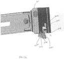
- the walls 44, 45 of the bracket 40 may have a slot 49 and the latch 60 may have a hole 79 for a fastener 900, such as a bolt, while in other embodiments ( FIG. 16 ) the walls 44, 45 of the bracket 40 include holes 49a and a slot 69 is formed in the latch 60.
- the slot 49/69 is sized to allow relative motion of the latch 60 with respect to the bracket 40 (which is fixed to the track 20, 30) to allow the latch 60 to slide away from the track 20, 30 (and against the biasing force of the spring 80) to provide for clearance between the latch and the central portions 29 of the track between adjacent apertures (e.g.
- the slot 49/69 may be disposed at an acute angle ⁇ with respect to an axis through the track, with an angle (when the finger 62 of the latch engages the lower edge (e.g. 22a) of the track 20.
- the acute angle may be about 45 degrees, or an angle within a range of about 30 to 60 degrees.
- the collar 140 may be pinned to the bracket 40 with the same fastener 500 that is used to pivotably mount the latch 60 to the bracket 40.
- the latch 60 has a second cam surface 68 which is an arcuate surface upon the circumferential surface of the latch 60.
- the second cam surface 68 may be disposed on an opposite side of the first cam surface 66 from the finger 62.
- the second cam surface is configured to contact a lower edge (e.g. 24a) of an aperture when the bracket 40 and the latch 60 are lowered within an aperture.
- the latch 60 is translated away from the track 20, 30 along the slot 49/69 such that the latch 60 clears the central portions 29 of the track 20, 30.
- a portion of the latch 60 extends into the next aperture.
- the bracket 40 and latch 60 may be further lowered to another lower aperture (and when the second cam surface 68 contacts the lower edge (e.g. 26a) of the aperture in registration with the latch, such contact again urges the latch 60 away from the track 20, 30 along the slot to provide clearance to travel downwardly past another central portion 29 of the track.
- the first cam surface 66 of the latch 60 contacts the upper edge (e.g. 26b) of the aperture, which causes the latch to rotate the second direction (Y, FIG. 8 ) against the biasing force of the spring 80 and urges the latch 60 away from the track 20, 30 to provide clearance to travel upwardly past a central portion 29 of the track 20, 30.
- the latch 60 may include a rotating portion 1002 and a guide 1004 that is rotatably connected to the rotating portion 1002 of the latch 60.
- the rotating portion 1002 may be rotatably mounted upon the bracket 40 and biased by a spring 1006, as discussed below.
- the rotating portion 1002 may include an upper portion 1008, a lower portion 1010 that extends generally perpendicularly from the upper portion 1008, and a bottom portion 1012 located below the lower portion 1010.
- the upper portion 1008 may include a hole 1030 through which the rotating portion 1002 is mounted on the bracket 40 such that the rotating portion 1002 is rotatable with respect to the bracket 40 about a rotating axis 1032 of the hole 1030 (and about a fastener, such as a pin, that mounts the latch 60 to the bracket 40).
- the lower portion 1010 may include an outer circumferential edge 1014 that defines third and fourth surfaces 1016 and 1018.
- the third surface 1016 may contact an upper edge (e.g. 22b, 24b, 26b) of an aperture in the track and urge the latch 60 to rotate upon the bracket 40 to properly position the latch 60 to engage the track with further motion of the bracket 40 and latch 60.
- the fourth surface 1018 may be a flat that rests upon a lower edge (e.g. 22a, 24a, 26a) of an aperture to allow the track to support the rotating portion 1002.
- the biasing force of the spring 1006 may interact with the rotating portion 1002 and cause the rotating portion 1002 to rotate in the direction Z ( FIG. 21 ), such that the lower portion 1010 (e.g. FIG. 28 ) or the lower portion 1010 together with the guide 1004 (e.g. FIG. 23 ) rotates towards and into the aligned aperture.
- the third surface 1016 contacts an upper edge (e.g.
- the rotating portion 1002 will be urged to rotate away from and out of the aligned aperture (and against the biasing force of the spring 1006) to provide for clearance between the rotating portion 1002 and the central portions 29 of the track between adjacent apertures (e.g. between apertures 22 and 24) to allow the rotating portion 1002 to slide upwardly and downwardly with respect to the tracks 20 and 30.
- the guide 1004 may include an outer circumferential edge 1026 that defines a fifth surface 1020, a sixth surface 1022, and a connecting surface 1024 connecting the fifth and sixth surfaces 1020 and 1022 together (which may be a surface or an edge).
- the guide 1004 may be rotatably connected to the bottom portion 1012 of the rotating portion 1002 (e.g. pin connection) and biased towards the rotating portion 1002 through a spring 1028.
- the fifth surface 1020 may be a flat that is biased by the spring 1028 to directly contact the fourth surface 1018 of the rotating portion 1002.
- the sixth surface 1022 may be an arcuate surface that is further away from the fourth surface 1018 than the fifth surface 1020.
- the sixth surface 1022 may be configured to contact a lower edge (e.g. 22a) of an aperture (e.g. 22) when the bracket 40 and the latch 60 are lowered within an aperture (e.g. 22).
- the latch 60 is urged to rotate away from the track such that the latch 60 clears the central portion 29 (e.g. between apertures 22 and 24) of the track (e.g. FIGs. 21-22 ).
- the latch 60 becomes aligned with the next aperture (e.g. 24), a portion of the latch 60 extends into the next aperture (e.g. 24, FIG. 23 ).
- the bracket 40 and latch 60 may be further lowered to another lower aperture (e.g. 26), and when the sixth surface 1022 contacts the lower edge (e.g. 24a) of the aperture (e.g. 24) in registration with the latch 60, such contact again urges the latch 60 away from the track to provide clearance to travel downwardly past another central portion 29 (e.g. between apertures 24 and 26) of the track (e.g. FIGs. 24-25 ).
- another central portion 29 e.g. between apertures 24 and 26
- the fifth surface 1020 may be longer than the fourth surface 1018, such that when the fourth and fifth surfaces 1018 and 1020 are contacting each other, a portion of the fifth surface 1020 may contact an upper edge (e.g. 22b, 24b, 26b) of an aperture in the track (e.g. FIG. 32 ), as the latch 60 has been rotated away from the track due to contact between the third surface 1016 and the upper edge of the aperture. If the final destination is an aperture (e.g. 22) above the current aperture (e.g. 24) in registration with the latch 60, the fifth surface 1020 of the guide 1004 contacts the upper edge (e.g. 24b) of the aperture (e.g. 24), which causes the guide 1004 to rotate in the direction Y (e.g. FIG.
- the bracket 40 When the bracket 40 is secured to the track through a desired aperture (e.g. 22) in the track, the lower portion 1010 of the rotating portion 1002 rests upon the lower edge (e.g., 22a) of the aperture (e.g. 22), and the connecting surface 1024 of the guide 1004 is biased against a central portion 29 below the aperture (e.g. 22) with the fifth surface 1020 of the guide 1004 extending at an acute angle ⁇ with respect to a longitudinal axis through the track (e.g. FIG. 20 ) and in some embodiments, the connecting surface 1024 contacting the central portion 29 of the track.
- the weight of the beam assembly 100 (and when load is applied the weight of the load upon the beam assembly) is transferred from the bracket 40, to the latch 60, and ultimately to the tracks 20 and 30 via a triangular supporting structure formed by the lower portion 1010 of the rotating portion 1002 resting upon the lower edge (e.g. 22a) of the aperture (e.g. 22) in the track 20, the guide 1004, and the central portion 29 of the track between the aperture (e.g. 22) and the aperture directly below (e.g. 24, FIG. 20 ).
- the triangular supporting structure provides a strong supporting force to the beam assembly 100, such that a strong loading strength can be achieved.
- the weight of the beam assembly 100 (or more specifically generally one half of the weight of the beam assembly 100 when the beam assembly is horizontal) is high enough to overcome the biasing force of springs 1006 and 1028 to maintain engagement between the lower portion 1010 of the rotating portion 1002 and the lower edge (e.g. 22a) of the aperture (e.g. 22) and the engagement between the connecting surface 1024 and the central portion 29 of the track between the aperture (e.g. 22) and the aperture directly below (e.g. 24).
- this embodiment of the latch 60 provides the ability to move the contacting point between the latch 60 and the track to a position lower than the rotating axis 1032 of the rotating portion 1002, which creates a compressive load path between the latch 60 and the track such that tensile loading may be reduced.
- this embodiment of the latch 60 may be incorporated into an automated decking system without the use of complicated electromechanical systems to release the latch 60 for moving the beam upwardly or downwardly.
- this embodiment of the latch 60 may provide substantial load-bearing properties, which improves the loading strength and increases the beam storage height (e.g. the beam can be stored higher toward the ceiling in a trailer thereby increasing clearance for cargo or forklift).
- the system 10 is controlled by an input device 2000, which receives instructions from the user regarding the desired height of the beam assembly 100, and in some embodiments, the desired heights of the opposite ends of the beam assembly 100.
- the input device 2000 may control each beam assembly separately and may also control all beam assemblies together as a single unit.
- the input device 2000 may include macros that can be selected by a user, such as to be programmed a certain group of beam assemblies 100 together to a certain height to receive certain cargo loads above, or below the certain beam assemblies.
- the input device 2000 may be a control box with inputs for all of the beam assemblies, which is positioned proximate to the open end of the cargo compartment such that a driver of a forklift could operate the input device in conjunction with loading or unloading a cargo compartment.
- the input device may be a smartphone, tablet or computer, and communicate with the control system via Bluetooth, Wi-Fi, the internet, or other mediums known in the art.
- the control system 2000a may communicate with each motor 605 in the system via a wired connection, or via Bluetooth, Wi-Fi, or other signal transmission processes known in the art.
- the input device 2000, the control system 2000a, and the motors 605 may be operated by batteries, such as rechargeable batteries.
- the system may be selectively powered by conventional AC power, which may charge the batteries and/or provide power to the system.
- control system (2000a, shown schematically with respect to the input device 2000) receives an input that is representative of the vertical position of the bracket 40 with respect to the track 20.
- the position input in some embodiments is with respect to the position of the apertures e.g. 22, 24, 26 along the track.
- the control system directs the operation of the motor in order to raise or lower the bracket 40 with respect to the track 20 and specifically with respect to the aperture that is desired for connection based upon the input into the input device 2000.
- the method includes the steps of controlling the vertical position of first and second brackets 40 that are connected to opposite first and second ends of a decking beam assembly 100, and which slide upwardly and downwardly along respective tracks 20, 30, based upon the operation of motors 605 that are connected to each bracket through a transmission, such as a drive belt 610 via a series of pulleys 622, 624, a lead screw drive, a cable drive, hydraulic cylinders, or pneumatic cylinders or the like.
- a transmission such as a drive belt 610 via a series of pulleys 622, 624, a lead screw drive, a cable drive, hydraulic cylinders, or pneumatic cylinders or the like.
- operation of the motor 605 in a first direction urges the bracket 40 (and therefore the end of the beam assembly 100 attached to the bracket 40) upwardly
- operation of the motor in the opposite second direction urges the bracket 40 (and end of the beam) downwardly along the track.
- a latch 60 that is pivotably and in some embodiments ( FIGs. 3-15 ) slidably mounted with respect to the bracket 40 rotates and translates as the latch is in sliding registration with apertures disposed along the track and the central portion 29 disposed between adjacent apertures.
- the methods include methods of lowering the end of the beam assembly 100, by lowering the bracket 40 slidably mounted to the first track 20, and is shown with reference to FIGs. (3-11 ) and (20-29).
- the methods described below will be a method of moving a vertical position of a bracket 40 upon a track 20, 30.
- this method will also result in the end of the beam assembly 100 attached to the bracket 40 moving with the bracket.
- the methods discussed below also explicitly refer to only moving one bracket along one track, but one of ordinary skill should understand that the method also may include the steps of moving the bracket fixed to the opposite end of the beam assembly along its track in the same manner (to maintain the beam assembly 100 in a horizontal orientation) or could entail moving the bracket fixed to the opposite end of the beam assembly in a differing manner (to result in the beam assembly 100 being in an angled orientation, such as may be desired for laterally shoring loads within a cargo compartment).
- the method of lowering an end of the beam assembly 100 begins with an initial condition with the finger 62 of the latch engaging the lower edge 22a of a first aperture 22 and ends with the finger 62 of the latch 60 engaging an aperture 24 directly below the aperture 22 ( FIG. 3 ).
- the same method can be used for lowering the bracket 40 to other apertures in the track that are lower than aperture 24 using the same steps as described herein.
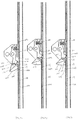
- the bracket 40 is raised vertically such that the finger 62 no longer contacts the lower edge 22a of the aperture 22, and with sufficient vertical motion, the body of the latch 60 clears the lower edge 22a and is free to rotate in the first direction Z due to the biasing force of the spring 80. In this position, a portion of the latch 60 including the second cam surface 68 extends through the aperture 22 and the finger 62 is outside of the aperture 22.
- the bracket 40 is lowered until the second cam surface 68 contacts the lower edge 22a of the aperture 22, which pushes the latch 60 away from the track 20 (via the slot 49 in the bracket 40, or the slot 69 in the latch 60 - see arrow T) to allow the bracket 40 and latch 60 to slide downwardly along the central portion 29 of the track between aperture 22 and aperture 24 ( FIG. 6 ), which is adjacent to and below aperture 22 (and in this method is where the bracket will be ultimately fixed to).
- the bracket 40 continues to slide past aperture 24.
- a portion of the latch, including the second cam surface 68 extends within the aperture (with the finger 62 extending outside of the aperture) (similar to the orientation depicted in FIG. 4 with respect to the aperture 22) until the latch reaches the bottom edge 24a, which slides the latch 60 away from the track 20 to allow the bracket 40 and latch 60 to slide past the central portion 29 between apertures 24 and adjacent lower aperture 26 (similar to the orientations depicted in FIGs. 5 and 6 ).
- a portion of the latch 60 when in registry with the aperture 26, as discussed above, extends through aperture 26, including the first cam surface 66 and the second cam surface 68, with the finger 62 outside of the aperture, as depicted in FIG. 7 .
- the bracket 40 is raised along the track 20 until the first cam surface 66 contacts the upper edge 26b of the aperture 26, which causes the latch 60 to rotate in the second direction Y ( FIG. 8 ) and also slide away from the track 20 (direction T) such that the latch 60 is free to slide vertically along the central portion 29 of the track toward the aperture 24 ( FIG. 9 ).
- the bracket is slid until the finger 62 is in registry with the aperture 24 and above the lower edge 24a, and the finger 62 is then urged through the aperture due to the biasing force of the spring 80 ( FIG. 10 ).
- the bracket is lowered slightly from the vertical position (distance P) where the finger 62 as extended into the aperture 24 so that the flat 63 of the finger 62 rests upon the lower edge 24a of the aperture 24 ( FIG. 11 ).
- the weight of the beam assembly 100 is carried by the track 20 via the latch and the bracket 40 and the beam assembly 100 can be loaded as desired.
- a method of raising the bracket 40 (and end of the beam assembly 100) the end of the beam assembly 100, by raising the bracket 40 slidably mounted to the first track 20 is discussed below, and is shown with reference to FIGs. 11-15 .
- the method describes raising the bracket 40 to an aperture directly above the aperture that the bracket is aligned with in the initial condition of the method, but one of ordinary skill will understand that the method is equally applicable to raising the bracket across multiple apertures.
- the finger 62 of the latch 60 rests upon the lower edge 24a of the aperture 24 and an input is received to raise the bracket 40 to the aperture 22 above aperture 24.
- the bracket 40 is raised until the latch 60 is clear of the lower edge 24a, and the spring 80 urges the latch to rotate in the direction Z until the first and second cam surfaces 66, 68 extend through the aperture 24 as depicted in FIG. 12 .
- the bracket 40 As the bracket 40 continues to raise, the first cam surface 66 contacts the upper edge 24b of the aperture 24 ( FIG. 12 ), which causes the latch 60 to rotate in the second direction Y and also slide away from the track 20 (direction T) such that the latch 60 is free to slide vertically along the central portion 29 of the track toward the aperture 24 ( FIG. 13 ).
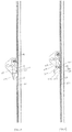
- the bracket is slid upwardly along the track until the finger 62 is in registry with the aperture 22 and above the lower edge 22a, and the finger 62 is then urged through the aperture due to the biasing force of the spring 80 ( FIG. 14 ).
- the bracket is lowered slightly from the vertical position where the finger 62 as extended into the aperture 22 (distance P) so that the flat 63 of the finger 62 rests upon the lower edge 22a of the aperture 22 ( FIG. 15 ).
- the weight of the beam assembly 100 is carried by the track 20 via the latch and the bracket 40 and the beam assembly 100 can be loaded as desired.
- FIGs. 20-35 another embodiment of the method of adjusting a decking system from one vertical position upon the vertical tracks 20 and 30 is described.
- the method includes a method of lowering the end of the beam assembly 100, by lowering the bracket 40 slidably mounted to the track 20, and is shown with reference to FIGs. 20-29 .
- the method of lowering an end of the beam assembly 100 begins with an initial condition with the rotating portion 1002 engaging the lower edge 22a of the aperture 22 ( FIG. 20 ) and ends with the rotating portion 1002 engaging the aperture 24 directly below the aperture 22 ( FIG. 29 ).
- One of ordinary skill will understand that the same method can be used for lowering the bracket 40 to other apertures in the track 20 that are lower than aperture 24 using the same steps as described herein.
- the bracket 40 is raised vertically such that the lower portion 1010 of the rotating portion 1002 no longer contacts the lower edge 22a of the aperture 22.
- the connecting surface 1024 clears the central portion 29 directly below the aperture 22, such that the guide 1004 rotates in the direction Z to contact the fourth surface 1018 of the rotating portion 1002 due to the biasing force of the spring 1028.
- a portion of the rotating portion 1002 and the guide 1004 extend through the aperture 22 with the sixth surface 1022 contacts the lower edge 22a of the aperture 22.
- the bracket 40 is lowered, which allows the contact between the sixth surface 1022 and the lower edge 22a of the aperture 22 to urge the latch 60 to rotate in the direction Y to allow the bracket 40 and latch 60 to slide downwardly along the central portion 29 of the track 20 between the apertures 22 and 24.
- the aperture 24 is adjacent to and below the aperture 22, and in this method is where the bracket 40 will be ultimately fixed to.
- the bracket 40 continues to slide past aperture 24 ( FIGs. 23-25 ).
- a portion of the rotating portion 1002 and guide 1004 extend within the aperture 24 ( FIG. 23 ), with the upper portion 1008 outside of the aperture 24, and the latch 60 is free to rotate in the direction Z until the sixth surface 1022 reaches the lower edge 24a.
- the bracket 40 is further lowered, which rotates the latch 60 in the direction Y to allow the bracket 40 and latch 60 to slide past the central portion 29 between the aperture 24 and adjacent lower aperture 26 ( FIGs. 24-25 ).
- the bracket 40 is raised along the track 20 until the fifth surface 1020 contacts the upper edge 26b of the aperture 26, which allows the contact between the third surface 1016 and the upper edge 26b of the aperture 26 to urge the latch 60 to rotate in the direction Y such that the latch 60 can be slid upwardly.
- the bracket 40 continues to slide upwardly, which causes the contact between the upper edge 26b of the aperture 26 and the fifth surface 1020 to urge the guide 1004 to rotate in the direction Y and out of contact with the fourth surface 1018, such that the latch 60 is free to slide vertically along the central portion 29 of the track 20 toward the aperture 24 ( FIG. 27 ).
- the connecting surface 1024 is biased against the aligned central portion 29 with the fifth surface 1020 extending at an acute angle ⁇ with respect to a longitudinal axis of the track 20 ( FIG. 27 ).
- the angle ⁇ may be larger than the angle a.
- the bracket 40 is slid until the lower portion 1010 of the rotating portion 1002 is in registry with the aperture 24 and above the lower edge 24a. The lower portion 1010 is then urged through the aperture 24 due to the biasing force of the spring 1006 ( FIG. 28 ). Then, the bracket 40 is lowered slightly from the vertical position (distance R) where the lower portion 1010 as extended into the aperture 24 so that the fourth surface 1018 of the rotating portion 1002 rests upon the lower edge 24a of the aperture 24 ( FIG. 29 ) and the connecting surface 1024 is biased against the central portion 29 between the apertures 24 and 26 with the fifth surface extending at the angle ⁇ with respect to the longitudinal axis of the track 20. In this configuration, the weight of the beam assembly 100 is carried by the track 20 via the latch 60 and the bracket 40, and the beam assembly 100 can be loaded as desired.
- a method of raising the end of the beam assembly 100, by raising the bracket 40 slidably mounted to the track 20 is discussed below, and is shown with reference to FIGs. 30-35 .
- the method describes raising the bracket 40 to an aperture directly above the aperture that the bracket is aligned with in the initial condition of the method, but one of ordinary skill will understand that the method is equally applicable to raising the bracket across multiple apertures.
- the fourth surface 1018 of the rotating portion 1002 rests upon the lower edge 24a of the aperture 24 and an input is received to raise the bracket 40 to the aperture 22 above the aperture 24.
- the bracket 40 is raised until the connecting surface 1024 is clear of the lower edge 24a, and the spring 1028 urges the guide 1004 to rotate in the direction Z until the fourth and fifth surfaces 1018 and 1020 contact each other.
- a portion of the lower portion 1010 of the rotating portion 1002 and the guide 1004 extend through the aperture 24 as depicted in FIG. 31 .
- the biasing force of the spring 1006 urges the latch 60 to rotate in the direction Z until the third surface 1016 contacts the upper edge 24b of the aperture 24 ( FIG. 31 ), which causes the rotating portion 1002 to rotate in the direction Y such that the rotating portion 1002 is free to slide vertically along the central portion 29 of the track 20 toward the aperture 22.
- the fifth surface 1020 contacts the upper edge 24b of the aperture 24, which causes the fifth surface 1020 to rotate in the direction Y and out of contact with the fourth surface 1018, such that the latch 60 is free to slide vertically along the central portion 29 of the track 20 toward the aperture 22.
- the connecting surface 1024 is biased against the aligned central portion 29 with the fifth surface 1020 extending at an acute angle ⁇ with respect to the longitudinal axis of the track 20 ( FIG. 33 ).
- the angle ⁇ may be larger than the angle a.
- the bracket 40 is slid upwardly along the track 20 until the lower portion 1010 of the rotating portion 1002 is in registry with the aperture 22 and above the lower edge 22a. The lower portion 1010 is then urged through the aperture 22 due to the biasing force of the spring 1006 ( FIG. 34 ). Then, the bracket 40 is lowered slightly from the vertical position (distance R) where the lower portion 1010 as extended into the aperture 22 so that the fourth surface 1018 of the rotating portion 1002 rests upon the lower edge 22a of the aperture 22 ( FIG. 35 ) and the connecting surface 1024 is biased against the central portion 29 of the track 20 between the apertures 22 and 24 with the fifth surface 1020 extending at the angle ⁇ with respect to the longitudinal axis of the track 20. In this configuration, the weight of the beam assembly 100 is carried by the track 20 via the latch 60 and the bracket 40, and the beam assembly 100 can be loaded as desired.
Description
- DELETED
- The disclosure relates to captive beam systems. Captive beam systems include decking beams with components that slide within vertical tracks fixed to opposite walls of a cargo compartment. The beam can be stowed close to the ceiling of the cargo compartment when not needed for use, and can be selectively lowered to a position for loading cargo or for shoring purposes. The ends of the beams slide within the track and include locking features that can selectively the ends of the beams with respect to the tracks at various heights along the track. The adjustment of height of captive beams is a manual process and often requires operators to load and unload a cargo compartment, a first operator to raise and lower the captive beams as desired and a second operator to drive a forklift to insert or remove the cargo from the cargo compartment. An automated method to raise and lower captive beams is desired to allow a single operator to efficiently load or unload a cargo compartment. Note that
DE102010037753A1 discloses a loading bar for setting and adjusting in or on a rail in a cargo space. This document is considered to be the prior art closest to the subject-matter of claim 1. - The claimed invention provides a remotely adjustable decking system. The system includes first and second vertical tracks that are configured to be installed upon opposing walls of cargo compartment, each of the first and second vertical tracks comprise a plurality of apertures disposed spacingly therealong, first and second brackets that each slide along the respective first and second tracks, and first and second motors that are disposed in conjunction with the respective first and second tracks, wherein each of the first and second motors are operatively engaged with each of the respective first and second brackets through one of belt drive, cable drive, lead screw, hydraulic cylinder, or pneumatic cylinder, wherein operation of each motor in a first direction causes the respective bracket to slide upwardly along the respective vertical track and operation of each motor in an opposite second direction causes the respective bracket to slide downwardly along the respective vertical track. A controller with user input capability is included, wherein the controller selectively controls the operation of the first and second motors to selectively raise or lower a vertical position one or both of the first and second brackets upon the respective first and second tracks in response to an input received from an input device.
- Herein, we also describe a latch for use with a remotely adjustable decking system to selectively position a bracket upon a track. The latch includes a rotating portion rotatably mounted upon the bracket and is biased by a first spring and a guide rotatably connected to the rotating portion and biased toward the rotating portion by a second spring.
- Herein, we also describe a method for adjusting a decking system. The method includes the steps of providing first and second vertical tracks on opposite walls of a cargo compartment, each of the first and second vertical tracks comprising a plurality of apertures disposed spacingly therealong, with first and second brackets slidably mounted upon the respective first and second vertical tracks, and first and second motors disposed in conjunction with the respective first and second tracks, wherein each of the first and second motors are operatively engaged with the respective first and second brackets with a transmission, wherein operation of each motor in a first direction causes the respective bracket to slide upwardly along the respective track and operation of each motor in an opposite second direction causes the respective bracket to slide downwardly along the respective track, and controlling the vertical position of the first and second brackets along the respective first and second tracks, based upon inputs from a user from an input device, by selectively controlling the operation of the first and second motors to selectively raise or lower a vertical position of one or both of the first and second brackets upon the respective first and second tracks.
- The above method may additionally include a method for lowering one of the first and second brackets along the respective vertical track from a position in registration with a first aperture of the plurality of apertures to a second position in registration with a second aperture below the first aperture. Then raising the bracket to a position where a latch rotatably mounted upon the bracket and biased by a spring is fully aligned with the first aperture, which causes the latch to rotate in a first rotational direction such that a portion of the latch extends into the first aperture and a finger of the latch extends outside of the first aperture due to a biasing force of the spring. Then lowering the bracket such that a cam surface contacts a lower edge of the first aperture, and then lowering the bracket until the bracket is in registration with a third aperture that is below the second aperture. Then raising the bracket such that a second cam surface of the latch contacts an upper edge of the third aperture, which urges the latch to rotate in a second direction, opposite to the first direction, such that the finger of the latch is aligned to extend into the second aperture when the bracket is further raised toward registration with the second aperture, stopping vertical motion of the bracket when reaching a position where the finger extends into the second aperture, such that the finger rests upon a lower edge of the second aperture.
- The above method may additionally include another method for lowering one of the first and second brackets along the respective vertical track from a position in registration with a first aperture of the plurality of apertures to a second position in registration with a second aperture below the first aperture. The method includes raising the bracket to a position where a latch rotatably mounted upon the bracket and biased by a spring is fully aligned with the first aperture, which causes the latch to rotate in a first rotational direction such that a guide of the latch extends into the first aperture and contacts a rotating portion of the latch. Then lowering the bracket such that a sixth surface of the latch contacts a lower edge of the first aperture, and then lowering the bracket until the bracket is in registration with a third aperture that is below the second aperture. Then raising the bracket such that a third surface and a fifth surface of the latch consecutively contacts an upper edge of the third aperture, which urges the latch to rotate in a second rotational direction opposite to the first rotational direction, such that a lower portion of the rotating portion of the latch is aligned to extend into the second aperture when the bracket is further raised toward registration with the second aperture. Then lowering the bracket such that a fourth surface of the latch rests upon a lower edge of the second aperture and the guide is biased against a track position between the second and third apertures.
- One or all of the above methods may include a method for raising one of the first and second brackets along the respective track from a position in registration with a first aperture of the plurality of apertures to a second position in registration with a second aperture above the first aperture. The method includes raising the bracket to a positon where a latch rotatably mounted upon the bracket and biased by a spring is fully aligned with the first aperture, which causes the latch to rotate in a first rotational direction such that a portion of the latch extends into the first aperture and a finger of the latch extends outside of the first aperture due a biasing force of the spring. Then continuing to raise the bracket until a flat cam surface of the latch contacts an upper edge of the first aperture, which causes the latch to rotate in a second direction opposite to the first direction, such that a finger of the latch is aligned to extend into the second aperture when the bracket is further raised toward registration with the second aperture. Then stopping vertical motion of the bracket when reaching a position where the finger extends into the second aperture, such that the finger rests upon a lower edge of the second aperture.
- One or all of the above methods may include another method for raising one of the first and second brackets along the respective track from a position in registration with a first aperture of the plurality of apertures to a second position in registration with a second aperture above the first aperture. The method includes raising the bracket to a position where a latch rotatably mounted upon the bracket and biased by a spring is fully aligned with the first aperture, which causes the latch to rotate in a first rotational direction such that a guide of the latch extends into the first aperture and contacts a rotating portion of the latch. Then continuing to raise the bracket such that a third surface and a fifth surface of the latch consecutively contact an upper edge of the first aperture, which urges the latch to rotate in a second rotational direction opposite to the first rotational direction, such that a lower portion of the rotating portion of the latch is aligned to extend into the second aperture when the bracket is further raised toward registration with the second aperture. Then lowering the bracket such that a fourth surface of the latch rests upon a lower edge of the second aperture and the guide is biased against a track position between the first and second apertures.
- Advantages of the present disclosure will become more apparent to those skilled in the art from the following description. The drawings and description are to be regarded as illustrative in nature and not as restrictive; the scope of the claimed invention is set out in the appended claims.
-
-
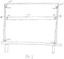
FIG. 1 is a schematic rear view of a captive beam system connected to opposite side walls of a cargo compartment, such as a trailer. -
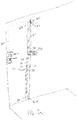
FIG. 1a is a schematic view of one track and a collar assembly (collar, bracket, latch) connected to an aperture in the track, schematically depicting a belt drive disposed between a set of pulleys and fixed with respect to the bracket. -
FIG. 2 is schematic view of the bracket upon the track with the belt removed but when installed the teeth of the belt are engageable with the peaks and valleys of the side wall of the bracket. -
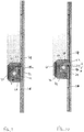
FIGs. 3-11 are side cross-sectional images of the bracket and latch with respect to the track as the alignment of the bracket is lowered from initial alignment withaperture 22 to final alignment withaperture 24. The images are depicted with the spring removed for simplicity, but the spring when provided bears against the bracket to urge the latch to rotate and slide with respect to the bracket and the track. -
FIGs. 12-15 are side cross-sectional images of the bracket and latch with respect to the track as the alignment of the bracket is raised from initial alignment withaperture 24 to final alignment withaperture 22. The images are depicted with the spring removed for simplicity, but the spring when provided bears against the bracket to urge the latch to rotate and slide with respect to the bracket and the track. -
FIG. 16 is the image ofFIG. 15 , depicting a slot disposed in the latch and a hole in the wall of the bracket to allow the latch to slide with respect to the bracket and the track. -
FIG. 17 is a top cross-sectional view depicting the latch in registry with a central portion of the track. -
FIG. 18 is a perspective view of the latch and the spring. -
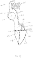
FIG. 19 is a side view of another version of the latch including a rotating portion and a guide. -
FIG. 19A is a perspective view of the latch ofFIG. 19 mounted on a bracket with the guide biased against the rotating portion. -
FIG. 19B is a perspective view of the latch ofFIG. 19 mounted on a bracket with the guide rotating out of contact with the rotating portion. -
FIGs. 20-29 are illustrations showing side cross-sectional views of the bracket and the latch ofFIG. 19 with respect to the track as the alignment of the bracket is lowered from initial alignment with theaperture 22 to final alignment with theaperture 24. -
FIGs. 30-35 are illustrations showing side cross-sectional views of the bracket and the latch ofFIG. 19 with respect to the track as the alignment of the bracket is raised from initial alignment with theaperture 24 to final alignment with theaperture 22. - Hereon in, "embodiment" can relate to an embodiment of the claimed invention (as per the appended claims) or to an embodiment that does not form part of the claimed invention but can represent background art useful for understanding the claimed invention.
Turning now toFIGS. 1-18 , a remotely operable system for controlling a captive beam 10 is shown. The system 10 allows for selectively raising and lowering abeam 130 that is operatively engaged between first andsecond tracks 20, 30 that are mounted upon opposite walls within a cargo container, such as the cargo compartment of a semi-trailer. The system 10 allows for a user to remotely set a height of thebeam 130 with the cargo compartment, either with the beam substantially horizontal, or with the beam disposed at an angle. - The system includes first and
second tracks 20, 30 that are disposed upon opposite sides of the cargo compartment. Each of the first andsecond tracks 20, 30 has a plurality ofapertures second tracks 20, 30 receives abracket 40 slidable therealong. Eachbracket 40 is slidable along the length of the respective track and selectively moved upward and downward with a motor 200, which when operating moves the position of thebracket 40 upon therespective track 20, 30 via a transmission 220 (which, in the claimed technology, is one of belt drive, cable drive, lead screw, hydraulic cylinder, or pneumatic cylinder). Eachbracket 40 may include one or two ormore fingers 42 that slide along corresponding 328 (FIG. 17 ) of the corresponding track to maintain the connection between thebracket 40 and thetrack 20, 30 along the length of thetrack 20, 30 (i.e. when the beam assembly 100 is secured at a selected position corresponding to an aperture in thetrack 20, 30 and when the beam assembly 100 is stowed near the ceiling of the cargo compartment when not in use). - While each vertical track and
bracket 40 is controlled by a dedicated motor 200 via a dedicated transmission 220 (as discussed above), for the sake of brevity the construction and operation of a single bracket system will be discussed herein. One of ordinary skill in the art will understand that thecorresponding bracket 40 that is connected to the opposite end of the beam assembly 100 from thebracket 40 being discussed in detail herein is constructed and operates in the same manner. In embodiments where the user desires to move thebeam 130 to another position but maintain the beam assembly 100 in a horizontal configuration, bothbrackets 40 that are connected to opposite ends of the same beam assembly 100 will be moved in exact same manner as discussed herein. In other embodiments, where the user may wish to move and/or retain the beam assembly 100 at an angle (i.e. not in a horizontal orientation) the controller 400 (discussed below) will operate the motors corresponding to the opposite ends of the beam assembly 100 in different manners to align the beam assembly 100 at an angle as desired, i.e. to achieve a resting position where the first andsecond brackets 40 that are associated with opposite first andsecond tracks 20, 30 rest upon the lower edge of apertures at different heights on the opposite tracks. - The beam assembly 100 may include an
elongate beam 130, and twocollars 140, which are telescopingly mounted to thebeam 130 to allow the length of the beam to selectively extend (when the beam is at an angle) and shorten (when the beam is horizontal). Eachcollar 140 is connected to abracket 40, such as with a pinned connection or other types of connections. Thecollar 140 may be pivotable with respect to thebracket 40. - The
bracket 40 is best shown inFIGs. 2 and17 . Thebracket 40 may include first andsecond walls support fingers 42 that ride within thetrack 20, 30 that thebracket 40 is slidably mounted to. In some embodiments, one of the first orsecond walls wall FIGs 1 and1a ) with respect to thewall bracket 40 to slide upwardly or downwardly upon therespective track 20, 30. As shown inFIG. 1a , the belt 610 may be wrapped around alower pulley 624 proximate to the lower end 21a of the track and anupper pulley 622 proximate to the upper end 21b of the track, and around the shaft of amotor 605, such that rotation of the shaft of themotor 605 in a first direction causes the belt 610 to pull thebracket 40 upward, and operation of themotor 605 in the opposite direction causes thebracket 40 to be pulled downward along thetrack 20. In some embodiments, a transmission (such as a second belt, or gears or the like) may be provided between the motor shaft and theupper pulley 622 to adjust the desired speed of the belt 610 with respect to the speed of themotor 605. - The
bracket 40 rotationally supports alatch 60, as best shown inFIG. 18 , with thelatch 60 mounted, in some embodiments, between thewalls bracket 40. Thelatch 60 is provided to engage with one of the plurality of apertures (e.g. 22, 24, 26) within thevertical track 20 to allow the weight of the beam assembly 100 (and including the significant load carried by the beam assembly 100 during use) to be supported by the vertical track, rather than the belt 610 (or other type of transmission to cause thebracket 40 to slide along thetrack 20, 30 supporting the weight of the beam assembly 100 and the load). - The
latch 60 includes afinger 62 that extends generally radially from the remaining body of thelatch 60 Thefinger 62 may include a flat 63 that is the surface that rests upon a lower edge (e.g. 22a, 24a, 26a) of an aperture to allow the track to support thelatch 60. In some embodiments, the finger further comprises a downwardly extendingtip 64 that defines a void 65 below the flat 63, where the lower edge (e.g. 24a) and the track below the lower edge is received. - The
latch 60 further includes an outercircumferential edge 61 that defines first and second cam surfaces 66, 68, which depending upon the relative position of thelatch 60 with respect to the track, contact the upper edge (e.g. 22b, 24b, 26b) of the track and urge thelatch 60 to rotate upon thebracket 40 to properly position thelatch 60 to engage the track with further motion of the bracket and latch. Thefist cam surface 66 may be a flat surface that is below thefinger 62 and extends along a wall that forms a portion of the void 65. Thesecond cam surface 68 may be an arcuate surface that is further away from thefinger 62 than thefirst cam surface 66. - The
latch 60 may be biased to rotate with respect to thebracket 40 with aspring 80. In some embodiments, thelatch 60 is biased to rotate in a direction away from engagement between thefinger 62 and a lower edge (e.g. 22a) of the track when the latch is in position for engagement between thefinger 62 and the track. As shown inFIGs. 3 and 4 , thespring 80 biases thelatch 60 in the counter-clock wise direction Z such that thefinger 62 rotates out of contact with the lower edge (22a) once thebracket 40 is raised slightly with respect to the track. As can be understood by one of ordinary skill with a thorough review of this specification and drawings, the weight of the beam assembly 100 (and when load is applied the weight of the load upon the beam assembly) is transferred from thebracket 40, to thelatch 60, and ultimately to thetrack 20, 30 via thefinger 62 resting upon the lower edge (e.g. 22a) of the aperture (e.g. 22) in thetrack 20. The weight of the beam assembly 100 (or more specifically generally one half of the weight of the beam assembly 100 when the beam assembly is horizontal) is high enough to overcome the biasing force of thespring 80 to maintain engagement between thefinger 62 and the lower edge of the aperture. - When the beam assembly 100 is unloaded (the system in some embodiments is configured for the beam assemblies 100 to be moved only when the beam assembly 100 is unloaded), the belt 610 pulls the
bracket 40 and therefore thelatch 60 upward, which causes thefinger 62 to disengage from the respective lower edge (24a). Upon the disengagement, the biasing force of thespring 80 interacts with thelatch 60 and causes the latch to rotate in the direction Z such that thefinger 62 rotates away from and out of the aligned aperture. In some embodiments, the rotation of thelatch 60 is such that when biased in the direction Z by the spring, alower portion 67 extends through the aperture (24) and thefirst cam surface 66 is directly below the upper edge (24b) of the aperture (24). - In some embodiments, the
latch 60 is slidable with respect to thebracket 40. In some embodiments (FIG. 3 ) thewalls bracket 40 may have aslot 49 and thelatch 60 may have ahole 79 for a fastener 900, such as a bolt, while in other embodiments (FIG. 16 ) thewalls bracket 40 include holes 49a and a slot 69 is formed in thelatch 60. Theslot 49/69 is sized to allow relative motion of thelatch 60 with respect to the bracket 40 (which is fixed to thetrack 20, 30) to allow thelatch 60 to slide away from thetrack 20, 30 (and against the biasing force of the spring 80) to provide for clearance between the latch and thecentral portions 29 of the track between adjacent apertures (e.g. betweenapertures 24 and 26) to allow the latch to slide upwardly and downwardly with respect to thetrack 20, 30. In some embodiments, theslot 49/69 may be disposed at an acute angle β with respect to an axis through the track, with an angle (when thefinger 62 of the latch engages the lower edge (e.g. 22a) of thetrack 20. The acute angle may be about 45 degrees, or an angle within a range of about 30 to 60 degrees. One of ordinary skill will understand with a thorough review of this specification that the value of the acute angle (if necessary at all) will be a function of the relative sizes and positions of the latch, bracket, and track, and one of ordinary skill in the art will be able to design a latch, bracket and track that move as disclosed herein without undue experimentation. In some embodiments, thecollar 140 may be pinned to thebracket 40 with the same fastener 500 that is used to pivotably mount thelatch 60 to thebracket 40. - As mentioned above, the
latch 60 has asecond cam surface 68 which is an arcuate surface upon the circumferential surface of thelatch 60. Thesecond cam surface 68 may be disposed on an opposite side of thefirst cam surface 66 from thefinger 62. The second cam surface is configured to contact a lower edge (e.g. 24a) of an aperture when thebracket 40 and thelatch 60 are lowered within an aperture. When thesecond cam surface 68 contacts the lower edge, thelatch 60 is translated away from thetrack 20, 30 along theslot 49/69 such that thelatch 60 clears thecentral portions 29 of thetrack 20, 30. Once thelatch 60 becomes aligned with the next aperture, a portion of thelatch 60 extends into the next aperture. Depending upon the final destination of thebracket 40 and latch 60 (based upon the final position of the beam assembly 100 as desired by the user, through the input device 2000) thebracket 40 andlatch 60 may be further lowered to another lower aperture (and when thesecond cam surface 68 contacts the lower edge (e.g. 26a) of the aperture in registration with the latch, such contact again urges thelatch 60 away from thetrack 20, 30 along the slot to provide clearance to travel downwardly past anothercentral portion 29 of the track. If the final destination is an aperture above the current aperture in registration with thelatch 60, thefirst cam surface 66 of thelatch 60 contacts the upper edge (e.g. 26b) of the aperture, which causes the latch to rotate the second direction (Y,FIG. 8 ) against the biasing force of thespring 80 and urges thelatch 60 away from thetrack 20, 30 to provide clearance to travel upwardly past acentral portion 29 of thetrack 20, 30. - Referring to
FIGs. 19-19B , in some embodiments, thelatch 60 may include arotating portion 1002 and aguide 1004 that is rotatably connected to therotating portion 1002 of thelatch 60. The rotatingportion 1002 may be rotatably mounted upon thebracket 40 and biased by aspring 1006, as discussed below. The rotatingportion 1002 may include anupper portion 1008, a lower portion 1010 that extends generally perpendicularly from theupper portion 1008, and a bottom portion 1012 located below the lower portion 1010. Theupper portion 1008 may include ahole 1030 through which therotating portion 1002 is mounted on thebracket 40 such that the rotatingportion 1002 is rotatable with respect to thebracket 40 about a rotating axis 1032 of the hole 1030 (and about a fastener, such as a pin, that mounts thelatch 60 to the bracket 40). The lower portion 1010 may include an outercircumferential edge 1014 that defines third andfourth surfaces latch 60 with respect to the track, thethird surface 1016 may contact an upper edge (e.g. 22b, 24b, 26b) of an aperture in the track and urge thelatch 60 to rotate upon thebracket 40 to properly position thelatch 60 to engage the track with further motion of thebracket 40 andlatch 60. Thefourth surface 1018 may be a flat that rests upon a lower edge (e.g. 22a, 24a, 26a) of an aperture to allow the track to support the rotatingportion 1002. - When the lower portion 1010 of the
rotating portion 1002 is in registry with an aperture in the track, the biasing force of thespring 1006 may interact with the rotatingportion 1002 and cause therotating portion 1002 to rotate in the direction Z (FIG. 21 ), such that the lower portion 1010 (e.g.FIG. 28 ) or the lower portion 1010 together with the guide 1004 (e.g.FIG. 23 ) rotates towards and into the aligned aperture. When thethird surface 1016 contacts an upper edge (e.g. 22b, 24b, 26b) of an aperture in the track, once thebracket 40 is raised slightly with respect to the track, the rotatingportion 1002 will be urged to rotate away from and out of the aligned aperture (and against the biasing force of the spring 1006) to provide for clearance between therotating portion 1002 and thecentral portions 29 of the track between adjacent apertures (e.g. betweenapertures 22 and 24) to allow therotating portion 1002 to slide upwardly and downwardly with respect to thetracks 20 and 30. - The
guide 1004 may include an outercircumferential edge 1026 that defines afifth surface 1020, asixth surface 1022, and a connectingsurface 1024 connecting the fifth andsixth surfaces guide 1004 may be rotatably connected to the bottom portion 1012 of the rotating portion 1002 (e.g. pin connection) and biased towards the rotatingportion 1002 through aspring 1028. Thefifth surface 1020 may be a flat that is biased by thespring 1028 to directly contact thefourth surface 1018 of therotating portion 1002. Thesixth surface 1022 may be an arcuate surface that is further away from thefourth surface 1018 than thefifth surface 1020. - The
sixth surface 1022 may be configured to contact a lower edge (e.g. 22a) of an aperture (e.g. 22) when thebracket 40 and thelatch 60 are lowered within an aperture (e.g. 22). When thesixth surface 1022 contacts the lower edge (e.g. 22a), thelatch 60 is urged to rotate away from the track such that thelatch 60 clears the central portion 29 (e.g. betweenapertures 22 and 24) of the track (e.g.FIGs. 21-22 ). Once thelatch 60 becomes aligned with the next aperture (e.g. 24), a portion of thelatch 60 extends into the next aperture (e.g. 24,FIG. 23 ). Depending upon the final destination of thebracket 40 and latch 60 (based upon the final position of the beam assembly 100 as desired by the user, through the input device 2000), thebracket 40 andlatch 60 may be further lowered to another lower aperture (e.g. 26), and when thesixth surface 1022 contacts the lower edge (e.g. 24a) of the aperture (e.g. 24) in registration with thelatch 60, such contact again urges thelatch 60 away from the track to provide clearance to travel downwardly past another central portion 29 (e.g. betweenapertures 24 and 26) of the track (e.g.FIGs. 24-25 ). - The
fifth surface 1020 may be longer than thefourth surface 1018, such that when the fourth andfifth surfaces fifth surface 1020 may contact an upper edge (e.g. 22b, 24b, 26b) of an aperture in the track (e.g.FIG. 32 ), as thelatch 60 has been rotated away from the track due to contact between thethird surface 1016 and the upper edge of the aperture. If the final destination is an aperture (e.g. 22) above the current aperture (e.g. 24) in registration with thelatch 60, thefifth surface 1020 of theguide 1004 contacts the upper edge (e.g. 24b) of the aperture (e.g. 24), which causes theguide 1004 to rotate in the direction Y (e.g.FIG. 33 ) and out of contact with the fourth surface 1018 (against the biasing force of the spring 1028) once thebracket 40 is raised slightly with respect to the track, so as to urge theguide 1004 away from the track to provide clearance to travel upwardly past a central portion 29 (e.g. betweenapertures 22 and 24) of the track (e.g.FIGs. 32-33 ). - When the
bracket 40 is secured to the track through a desired aperture (e.g. 22) in the track, the lower portion 1010 of therotating portion 1002 rests upon the lower edge (e.g., 22a) of the aperture (e.g. 22), and the connectingsurface 1024 of theguide 1004 is biased against acentral portion 29 below the aperture (e.g. 22) with thefifth surface 1020 of theguide 1004 extending at an acute angle α with respect to a longitudinal axis through the track (e.g.FIG. 20 ) and in some embodiments, the connectingsurface 1024 contacting thecentral portion 29 of the track. As can be understood by one of ordinary skill with a thorough review of this specification and drawings, the weight of the beam assembly 100 (and when load is applied the weight of the load upon the beam assembly) is transferred from thebracket 40, to thelatch 60, and ultimately to thetracks 20 and 30 via a triangular supporting structure formed by the lower portion 1010 of therotating portion 1002 resting upon the lower edge (e.g. 22a) of the aperture (e.g. 22) in thetrack 20, theguide 1004, and thecentral portion 29 of the track between the aperture (e.g. 22) and the aperture directly below (e.g. 24,FIG. 20 ). The triangular supporting structure provides a strong supporting force to the beam assembly 100, such that a strong loading strength can be achieved. The weight of the beam assembly 100 (or more specifically generally one half of the weight of the beam assembly 100 when the beam assembly is horizontal) is high enough to overcome the biasing force ofsprings rotating portion 1002 and the lower edge (e.g. 22a) of the aperture (e.g. 22) and the engagement between the connectingsurface 1024 and thecentral portion 29 of the track between the aperture (e.g. 22) and the aperture directly below (e.g. 24). - The configuration of this embodiment of the
latch 60 provides the ability to move the contacting point between thelatch 60 and the track to a position lower than the rotating axis 1032 of therotating portion 1002, which creates a compressive load path between thelatch 60 and the track such that tensile loading may be reduced. In addition, this embodiment of thelatch 60 may be incorporated into an automated decking system without the use of complicated electromechanical systems to release thelatch 60 for moving the beam upwardly or downwardly. As such, this embodiment of thelatch 60 may provide substantial load-bearing properties, which improves the loading strength and increases the beam storage height (e.g. the beam can be stored higher toward the ceiling in a trailer thereby increasing clearance for cargo or forklift). - The system 10 is controlled by an
input device 2000, which receives instructions from the user regarding the desired height of the beam assembly 100, and in some embodiments, the desired heights of the opposite ends of the beam assembly 100. In situations where a cargo compartment, for example, has multiple beam assemblies 100, theinput device 2000 may control each beam assembly separately and may also control all beam assemblies together as a single unit. In some embodiments, theinput device 2000 may include macros that can be selected by a user, such as to be programmed a certain group of beam assemblies 100 together to a certain height to receive certain cargo loads above, or below the certain beam assemblies. Theinput device 2000 may be a control box with inputs for all of the beam assemblies, which is positioned proximate to the open end of the cargo compartment such that a driver of a forklift could operate the input device in conjunction with loading or unloading a cargo compartment. In other embodiments, the input device may be a smartphone, tablet or computer, and communicate with the control system via Bluetooth, Wi-Fi, the internet, or other mediums known in the art. Further, the control system 2000a may communicate with eachmotor 605 in the system via a wired connection, or via Bluetooth, Wi-Fi, or other signal transmission processes known in the art. - In some embodiments, the
input device 2000, the control system 2000a, and themotors 605 may be operated by batteries, such as rechargeable batteries. In other embodiments, the system may be selectively powered by conventional AC power, which may charge the batteries and/or provide power to the system. - Further, the control system (2000a, shown schematically with respect to the input device 2000) receives an input that is representative of the vertical position of the
bracket 40 with respect to thetrack 20. The position input in some embodiments is with respect to the position of the apertures e.g. 22, 24, 26 along the track. The control system directs the operation of the motor in order to raise or lower thebracket 40 with respect to thetrack 20 and specifically with respect to the aperture that is desired for connection based upon the input into theinput device 2000. - Turning now to
FIGs, 3-15 and20-35 , methods of adjusting a decking system from one vertical position upon first and second vertical tracks are described. The method includes the steps of controlling the vertical position of first andsecond brackets 40 that are connected to opposite first and second ends of a decking beam assembly 100, and which slide upwardly and downwardly alongrespective tracks 20, 30, based upon the operation ofmotors 605 that are connected to each bracket through a transmission, such as a drive belt 610 via a series ofpulleys motor 605 in a first direction urges the bracket 40 (and therefore the end of the beam assembly 100 attached to the bracket 40) upwardly, and operation of the motor in the opposite second direction urges the bracket 40 (and end of the beam) downwardly along the track. With motion of thebracket 40 along the track, alatch 60 that is pivotably and in some embodiments (FIGs. 3-15 ) slidably mounted with respect to thebracket 40 rotates and translates as the latch is in sliding registration with apertures disposed along the track and thecentral portion 29 disposed between adjacent apertures. - The methods include methods of lowering the end of the beam assembly 100, by lowering the
bracket 40 slidably mounted to thefirst track 20, and is shown with reference toFIGs. (3-11 ) and (20-29). For the sake of brevity in this description, the methods described below will be a method of moving a vertical position of abracket 40 upon atrack 20, 30. One of ordinary skill in the art should understand that this method will also result in the end of the beam assembly 100 attached to thebracket 40 moving with the bracket. The methods discussed below also explicitly refer to only moving one bracket along one track, but one of ordinary skill should understand that the method also may include the steps of moving the bracket fixed to the opposite end of the beam assembly along its track in the same manner (to maintain the beam assembly 100 in a horizontal orientation) or could entail moving the bracket fixed to the opposite end of the beam assembly in a differing manner (to result in the beam assembly 100 being in an angled orientation, such as may be desired for laterally shoring loads within a cargo compartment). - In some embodiments, as shown in
FIGs. 3-15 , the method of lowering an end of the beam assembly 100 begins with an initial condition with thefinger 62 of the latch engaging thelower edge 22a of afirst aperture 22 and ends with thefinger 62 of thelatch 60 engaging anaperture 24 directly below the aperture 22 (FIG. 3 ). One of ordinary skill will understand that the same method can be used for lowering thebracket 40 to other apertures in the track that are lower thanaperture 24 using the same steps as described herein. - In a first step depicted in
FIG. 4 , thebracket 40 is raised vertically such that thefinger 62 no longer contacts thelower edge 22a of theaperture 22, and with sufficient vertical motion, the body of thelatch 60 clears thelower edge 22a and is free to rotate in the first direction Z due to the biasing force of thespring 80. In this position, a portion of thelatch 60 including thesecond cam surface 68 extends through theaperture 22 and thefinger 62 is outside of theaperture 22. - Next, as shown in
FIG. 5 , thebracket 40 is lowered until thesecond cam surface 68 contacts thelower edge 22a of theaperture 22, which pushes thelatch 60 away from the track 20 (via theslot 49 in thebracket 40, or the slot 69 in the latch 60 - see arrow T) to allow thebracket 40 and latch 60 to slide downwardly along thecentral portion 29 of the track betweenaperture 22 and aperture 24 (FIG. 6 ), which is adjacent to and below aperture 22 (and in this method is where the bracket will be ultimately fixed to). - The
bracket 40 continues to slidepast aperture 24. When the latch is in registry withaperture 24, a portion of the latch, including thesecond cam surface 68 extends within the aperture (with thefinger 62 extending outside of the aperture) (similar to the orientation depicted inFIG. 4 with respect to the aperture 22) until the latch reaches thebottom edge 24a, which slides thelatch 60 away from thetrack 20 to allow thebracket 40 and latch 60 to slide past thecentral portion 29 betweenapertures 24 and adjacent lower aperture 26 (similar to the orientations depicted inFIGs. 5 and 6 ). - When the
bracket 40reaches aperture 26, a portion of thelatch 60, when in registry with theaperture 26, as discussed above, extends throughaperture 26, including thefirst cam surface 66 and thesecond cam surface 68, with thefinger 62 outside of the aperture, as depicted inFIG. 7 . - Next, the
bracket 40 is raised along thetrack 20 until thefirst cam surface 66 contacts the upper edge 26b of theaperture 26, which causes thelatch 60 to rotate in the second direction Y (FIG. 8 ) and also slide away from the track 20 (direction T) such that thelatch 60 is free to slide vertically along thecentral portion 29 of the track toward the aperture 24 (FIG. 9 ). The bracket is slid until thefinger 62 is in registry with theaperture 24 and above thelower edge 24a, and thefinger 62 is then urged through the aperture due to the biasing force of the spring 80 (FIG. 10 ). In embodiments where the finger includes an extendingtip 64, the bracket is lowered slightly from the vertical position (distance P) where thefinger 62 as extended into theaperture 24 so that the flat 63 of thefinger 62 rests upon thelower edge 24a of the aperture 24 (FIG. 11 ). In this orientation, the weight of the beam assembly 100 is carried by thetrack 20 via the latch and thebracket 40 and the beam assembly 100 can be loaded as desired. - A method of raising the bracket 40 (and end of the beam assembly 100) the end of the beam assembly 100, by raising the
bracket 40 slidably mounted to thefirst track 20 is discussed below, and is shown with reference toFIGs. 11-15 . The method describes raising thebracket 40 to an aperture directly above the aperture that the bracket is aligned with in the initial condition of the method, but one of ordinary skill will understand that the method is equally applicable to raising the bracket across multiple apertures. - As depicted in
FIG. 11 , thefinger 62 of thelatch 60 rests upon thelower edge 24a of theaperture 24 and an input is received to raise thebracket 40 to theaperture 22 aboveaperture 24. Thebracket 40 is raised until thelatch 60 is clear of thelower edge 24a, and thespring 80 urges the latch to rotate in the direction Z until the first and second cam surfaces 66, 68 extend through theaperture 24 as depicted inFIG. 12 . - As the
bracket 40 continues to raise, thefirst cam surface 66 contacts the upper edge 24b of the aperture 24 (FIG. 12 ), which causes thelatch 60 to rotate in the second direction Y and also slide away from the track 20 (direction T) such that thelatch 60 is free to slide vertically along thecentral portion 29 of the track toward the aperture 24 (FIG. 13 ). The bracket is slid upwardly along the track until thefinger 62 is in registry with theaperture 22 and above thelower edge 22a, and thefinger 62 is then urged through the aperture due to the biasing force of the spring 80 (FIG. 14 ). In embodiments where the finger includes an extendingtip 64, the bracket is lowered slightly from the vertical position where thefinger 62 as extended into the aperture 22 (distance P) so that the flat 63 of thefinger 62 rests upon thelower edge 22a of the aperture 22 (FIG. 15 ). In this orientation, the weight of the beam assembly 100 is carried by thetrack 20 via the latch and thebracket 40 and the beam assembly 100 can be loaded as desired. - Turning now to
FIGs. 20-35 , another embodiment of the method of adjusting a decking system from one vertical position upon thevertical tracks 20 and 30 is described. The method includes a method of lowering the end of the beam assembly 100, by lowering thebracket 40 slidably mounted to thetrack 20, and is shown with reference toFIGs. 20-29 . - The method of lowering an end of the beam assembly 100 begins with an initial condition with the rotating
portion 1002 engaging thelower edge 22a of the aperture 22 (FIG. 20 ) and ends with the rotatingportion 1002 engaging theaperture 24 directly below the aperture 22 (FIG. 29 ). One of ordinary skill will understand that the same method can be used for lowering thebracket 40 to other apertures in thetrack 20 that are lower thanaperture 24 using the same steps as described herein. - As shown in
FIG. 20 , when the rotatingportion 1002 is engaging thelower edge 22a of theaperture 22, the lower portion 1010 of therotating portion 1002 rests upon thelower edge 22a of theaperture 22, and the connectingsurface 1024 of theguide 1004 is biased against acentral portion 29 directly below theaperture 22 with thefifth surface 1020 of theguide 1004 extending at an acute angle α with respect to a longitudinal axis through thetrack 20. - In a first step depicted in
FIG. 21 , thebracket 40 is raised vertically such that the lower portion 1010 of therotating portion 1002 no longer contacts thelower edge 22a of theaperture 22. With sufficient vertical motion (e.g. 0.5 - 1 inch), the connectingsurface 1024 clears thecentral portion 29 directly below theaperture 22, such that theguide 1004 rotates in the direction Z to contact thefourth surface 1018 of therotating portion 1002 due to the biasing force of thespring 1028. In this position, a portion of therotating portion 1002 and theguide 1004 extend through theaperture 22 with thesixth surface 1022 contacts thelower edge 22a of theaperture 22. - Next, as shown in
FIG. 22 , thebracket 40 is lowered, which allows the contact between thesixth surface 1022 and thelower edge 22a of theaperture 22 to urge thelatch 60 to rotate in the direction Y to allow thebracket 40 and latch 60 to slide downwardly along thecentral portion 29 of thetrack 20 between theapertures aperture 24 is adjacent to and below theaperture 22, and in this method is where thebracket 40 will be ultimately fixed to. - The
bracket 40 continues to slide past aperture 24 (FIGs. 23-25 ). When therotating portion 1002 is in registry withaperture 24, a portion of therotating portion 1002 and guide 1004 extend within the aperture 24 (FIG. 23 ), with theupper portion 1008 outside of theaperture 24, and thelatch 60 is free to rotate in the direction Z until thesixth surface 1022 reaches thelower edge 24a. Then thebracket 40 is further lowered, which rotates thelatch 60 in the direction Y to allow thebracket 40 and latch 60 to slide past thecentral portion 29 between theaperture 24 and adjacent lower aperture 26 (FIGs. 24-25 ). - When the
bracket 40 reaches theaperture 26, a portion of theguide 1004 extends through theaperture 26, with thethird surface 1016 contacting the upper edge 26b of theaperture 26 and theupper portion 1008 outside of theaperture 26, as depicted inFIG. 26 . - Next, the
bracket 40 is raised along thetrack 20 until thefifth surface 1020 contacts the upper edge 26b of theaperture 26, which allows the contact between thethird surface 1016 and the upper edge 26b of theaperture 26 to urge thelatch 60 to rotate in the direction Y such that thelatch 60 can be slid upwardly. Thebracket 40 continues to slide upwardly, which causes the contact between the upper edge 26b of theaperture 26 and thefifth surface 1020 to urge theguide 1004 to rotate in the direction Y and out of contact with thefourth surface 1018, such that thelatch 60 is free to slide vertically along thecentral portion 29 of thetrack 20 toward the aperture 24 (FIG. 27 ). When thelatch 60 is moving upwardly along thecentral portion 29 of thetrack 20 between theapertures fifth surface 1020 is longer than thefourth surface 1018, the connectingsurface 1024 is biased against the alignedcentral portion 29 with thefifth surface 1020 extending at an acute angle µ with respect to a longitudinal axis of the track 20 (FIG. 27 ). The angle µ may be larger than the angle a. - The
bracket 40 is slid until the lower portion 1010 of therotating portion 1002 is in registry with theaperture 24 and above thelower edge 24a. The lower portion 1010 is then urged through theaperture 24 due to the biasing force of the spring 1006 (FIG. 28 ). Then, thebracket 40 is lowered slightly from the vertical position (distance R) where the lower portion 1010 as extended into theaperture 24 so that thefourth surface 1018 of therotating portion 1002 rests upon thelower edge 24a of the aperture 24 (FIG. 29 ) and the connectingsurface 1024 is biased against thecentral portion 29 between theapertures track 20. In this configuration, the weight of the beam assembly 100 is carried by thetrack 20 via thelatch 60 and thebracket 40, and the beam assembly 100 can be loaded as desired. - A method of raising the end of the beam assembly 100, by raising the
bracket 40 slidably mounted to thetrack 20 is discussed below, and is shown with reference toFIGs. 30-35 . The method describes raising thebracket 40 to an aperture directly above the aperture that the bracket is aligned with in the initial condition of the method, but one of ordinary skill will understand that the method is equally applicable to raising the bracket across multiple apertures. - As depicted in
FIGs. 30-31 , thefourth surface 1018 of therotating portion 1002 rests upon thelower edge 24a of theaperture 24 and an input is received to raise thebracket 40 to theaperture 22 above theaperture 24. Thebracket 40 is raised until the connectingsurface 1024 is clear of thelower edge 24a, and thespring 1028 urges theguide 1004 to rotate in the direction Z until the fourth andfifth surfaces rotating portion 1002 and theguide 1004 extend through theaperture 24 as depicted inFIG. 31 . - As the
bracket 40 continues to raise, the biasing force of thespring 1006 urges thelatch 60 to rotate in the direction Z until thethird surface 1016 contacts the upper edge 24b of the aperture 24 (FIG. 31 ), which causes the rotatingportion 1002 to rotate in the direction Y such that the rotatingportion 1002 is free to slide vertically along thecentral portion 29 of thetrack 20 toward theaperture 22. Then thefifth surface 1020 contacts the upper edge 24b of theaperture 24, which causes thefifth surface 1020 to rotate in the direction Y and out of contact with thefourth surface 1018, such that thelatch 60 is free to slide vertically along thecentral portion 29 of thetrack 20 toward theaperture 22. When thelatch 60 is moving along thecentral portion 29 of thetrack 20 between theapertures fifth surface 1020 is longer than thefourth surface 1018, the connectingsurface 1024 is biased against the alignedcentral portion 29 with thefifth surface 1020 extending at an acute angle µ with respect to the longitudinal axis of the track 20 (FIG. 33 ). The angle µ may be larger than the angle a. - The
bracket 40 is slid upwardly along thetrack 20 until the lower portion 1010 of therotating portion 1002 is in registry with theaperture 22 and above thelower edge 22a. The lower portion 1010 is then urged through theaperture 22 due to the biasing force of the spring 1006 (FIG. 34 ). Then, thebracket 40 is lowered slightly from the vertical position (distance R) where the lower portion 1010 as extended into theaperture 22 so that thefourth surface 1018 of therotating portion 1002 rests upon thelower edge 22a of the aperture 22 (FIG. 35 ) and the connectingsurface 1024 is biased against thecentral portion 29 of thetrack 20 between theapertures fifth surface 1020 extending at the angle α with respect to the longitudinal axis of thetrack 20. In this configuration, the weight of the beam assembly 100 is carried by thetrack 20 via thelatch 60 and thebracket 40, and the beam assembly 100 can be loaded as desired. - While the preferred embodiments of the disclosed technology have been described, it should be understood that the disclosure is not so limited and modifications may be made without departing from the disclosure. For example, it is contemplated that the adjustable decking assembly according to the present disclosure may also be used outside vehicle compartments, such as in storage facilities. The scope of the claimed invention is defined by the appended claims.
Claims (15)
- A remotely adjustable decking system, comprising:first and second vertical tracks (20) that are configured to be installed upon opposing walls of a cargo compartment, each of the first and second vertical tracks (20) comprising a plurality of apertures (22, 24, 26) disposed spacingly therealong;first and second brackets (40) that each slide along the respective first and second tracks (20); andfirst and second motors (200) that are disposed in conjunction with the respective first and second tracks (20), wherein each of the first and second motors (200) is operatively engaged with each of the respective first and second brackets (40) through one of belt drive, cable drive, lead screw, hydraulic cylinder, or pneumatic cylinder,characterized in thatoperation of each motor (200) in a first direction causes the respective bracket (40) to slide upwardly along the respective vertical track (20) and operation of each motor (200) in an opposite second direction causes the respective bracket (40) to slide downwardly along the respective vertical track (20);and in that the system further comprisesa controller (400) with user input capability, wherein the controller (400) selectively controls the operation of the first and second motors (200) to selectively raise or lower a vertical position of one or both of the first and second brackets (40) upon the respective first and second tracks (20) in response to an input received from an input device (2000).
- The remotely adjustable decking system of claim 1, further comprising an elongate decking beam (130) disposed between and fixed to the first and second brackets (40).
- The remotely adjustable decking system of claim 1, wherein the first and second brackets (40) rotatably support a first latch (60) and a second latch (60) respectively, wherein each of the first and second latches (60) is biased toward the respective vertical track (20) with a spring (80).
- The remotely adjustable decking system of claim 3, wherein each of the first and second latches (60) comprises:a rotating portion (1002) rotatably mounted upon a respective bracket (40); anda guide (1004) rotatably connected to the rotating portion (1002) and biased toward the rotating portion (1002) through a second spring (1028).
- The remotely adjustable decking system of claim 4, wherein the rotating portion comprises:an upper portion (1008);a lower portion (1010) comprising a third surface (1016) and a fourth surface (1018); anda bottom portion (1012),wherein the lower portion (1010) is configured to rest upon a lower edge (22a, 24a, 26a) of a respective aperture (22, 24, 26) when the bracket (40) is horizontally aligned with the lower edge (22a, 24a, 26a), such that the lower edge (22a, 24a, 26a) supports the bracket (40).
- The remotely adjustable decking system of claim 5, wherein the guide comprises:a fifth surface (1020);a sixth surface (1022); anda connecting surface (1024) connecting the fifth and sixth surfaces (1020, 1022) together, wherein the fifth surface (1020) is biased such that it contacts the fourth surface (1018) of the rotating portion (1002) to allow the rotating portion (1002) and the guide (1004) of the latch (60) to be moved together within an aperture.
- The remotely adjustable decking system of claim 4, wherein when the respective bracket (40) is secured to the respective vertical track (20), a portion of the rotating portion (1002) rests upon a lower edge (22a, 24a, 26a) of a respective aperture (22, 24, 26), and a portion of the guide (1004) is biased against a central portion (29) of the respective vertical track (20), such that a triangular supporting structure is formed to support the respective bracket (40).
- The remotely adjustable decking system of claim 6, wherein when the respective bracket (40) is secured to the respective vertical track (20), the lower portion (1010) of the rotating portion (1002) of the latch (60) rests upon the lower edge of the respective aperture, and the connecting surface (1024) of the guide (1004) is biased against a central portion (29) of the respective vertical track below the respective aperture, with the fifth surface (1020) extending at a first angle (µ) with respect to a longitudinal axis through the respective vertical track (20).
- The remotely adjustable decking system of claim 8, wherein when the bracket (40) is raised vertically from the respective aperture such that the connecting surface (1024) is clear of the lower edge of the respective aperture, the guide (1004) is configured to rotate in a first rotational direction to contact the fourth surface (1018) of the rotating portion due to the biasing force of the second spring.
- The remotely adjustable decking system of claim 9, wherein when the bracket continues to raise, the biasing force of the spring urges the rotating portion (1002) and the guide to rotate in the first rotational direction until the third surface (1016) contacts an upper edge (22b, 24b, 26b) of the respective aperture (22, 24, 26).
- The remotely adjustable decking system of claim 10, wherein when the bracket (40) continues to raise, the contact between the third surface (1016) and the upper edge (22b, 24b, 26b) of the respective aperture (22, 24, 26) causes the rotating portion (1002) to rotate in a second rotational direction such that the rotating portion (1002) is free to slide vertically along the central portion (29) of the respective vertical track toward a higher aperture of the plurality of apertures (22, 24, 26).
- The remotely adjustable decking system of claim 11, wherein the fifth surface (1020) is longer than the fourth surface (1018), such that further vertical motion of the bracket (40) causes the fifth surface (1020) to contact the upper edge (22b, 24b, 26b) of the respective aperture (22, 24, 26), which urges the fifth surface (1020) to rotate in the second rotational direction and out of contact with the fourth surface (1018), such that the guide (1004) is free to slide vertically along the central portion (29) of the respective vertical track (20) toward the higher aperture of the plurality of apertures (22, 24, 26).
- The remotely adjustable decking system of claim 12, wherein still further vertical motion of the bracket (40) with respect to the respective vertical track (20) brings the latch (60) into alignment with the higher aperture of the plurality of apertures (22, 24, 26), wherein when the lower portion (1010) of the rotating portion (1002) extends above the lower edge of the higher aperture (22, 24, 26), the lower portion (1010) is urged through the higher aperture of the plurality of apertures (22, 24, 26) due to the biasing force of the spring, preferably wherein when the bracket (40) is lowered from a vertical position where the lower portion as extended into the higher aperture, the fourth surface (1018) of the rotating portion (1002) rests upon the lower edge of the higher aperture with the fifth surface (1020) of the guide (1004) extending at the first angle with respect to the longitudinal axis of the respective vertical track (20).
- The remotely adjustable decking system of claim 12, wherein the guide slides vertically along the central portion (29) of the respective vertical track (20) toward the higher aperture of the plurality of apertures (22, 24, 26) with the fifth surface (1020) extending at a second angle different from the first angle with respect to the longitudinal axis through the respective vertical track (20).
- The remotely adjustable decking system of claim 9, wherein the sixth surface (1022) of the guide (1004) contacts the lower edge of the respective aperture (22, 24, 26), and wherein when the bracket (40) is lowered vertically, the latch (60) is urged to rotate away from the respective vertical track (20) in a second rotational direction to allow the latch (60) to slide further downward with respect to the respective vertical track (20) past a track position between adjacent apertures (22, 24, 26), preferably wherein further vertical motion of the bracket (40) with respect to the respective vertical track (20) brings the latch (60) into alignment with a lower aperture of the plurality of apertures (22, 24, 26), wherein when the lower portion of the rotating portion (1002) extends below an upper edge (22b, 24b, 26b) of the lower aperture (22, 24, 26), the lower portion and the guide (1004) are urged through the lower aperture due to the biasing force of the spring, which causes the latch (60) to rotate in the first direction.
Priority Applications (1)
| Application Number | Priority Date | Filing Date | Title |
|---|---|---|---|
| EP20171592.7A EP3722150B1 (en) | 2018-03-02 | 2019-02-26 | A latch for use with a remotely adjustable decking system |
Applications Claiming Priority (2)
| Application Number | Priority Date | Filing Date | Title |
|---|---|---|---|
| US201862637687P | 2018-03-02 | 2018-03-02 | |
| PCT/US2019/019581 WO2019168846A1 (en) | 2018-03-02 | 2019-02-26 | Remotely adjustable captive beam system |
Related Child Applications (2)
| Application Number | Title | Priority Date | Filing Date |
|---|---|---|---|
| EP20171592.7A Division-Into EP3722150B1 (en) | 2018-03-02 | 2019-02-26 | A latch for use with a remotely adjustable decking system |
| EP20171592.7A Division EP3722150B1 (en) | 2018-03-02 | 2019-02-26 | A latch for use with a remotely adjustable decking system |
Publications (3)
| Publication Number | Publication Date |
|---|---|
| EP3551499A1 EP3551499A1 (en) | 2019-10-16 |
| EP3551499A4 EP3551499A4 (en) | 2019-11-27 |
| EP3551499B1 true EP3551499B1 (en) | 2020-06-17 |
Family
ID=67137881
Family Applications (2)
| Application Number | Title | Priority Date | Filing Date |
|---|---|---|---|
| EP20171592.7A Active EP3722150B1 (en) | 2018-03-02 | 2019-02-26 | A latch for use with a remotely adjustable decking system |
| EP19721507.2A Active EP3551499B1 (en) | 2018-03-02 | 2019-02-26 | Remotely adjustable captive beam system |
Family Applications Before (1)
| Application Number | Title | Priority Date | Filing Date |
|---|---|---|---|
| EP20171592.7A Active EP3722150B1 (en) | 2018-03-02 | 2019-02-26 | A latch for use with a remotely adjustable decking system |
Country Status (7)
| Country | Link |
|---|---|
| US (2) | US11208028B2 (en) |
| EP (2) | EP3722150B1 (en) |
| JP (1) | JP7241779B2 (en) |
| AU (1) | AU2019204046A1 (en) |
| CA (1) | CA3046445A1 (en) |
| MX (2) | MX2019007871A (en) |
| WO (1) | WO2019168846A1 (en) |
Families Citing this family (6)
| Publication number | Priority date | Publication date | Assignee | Title |
|---|---|---|---|---|
| US11199012B2 (en) * | 2019-10-10 | 2021-12-14 | Titan Formwork Systems, Llc | Adjustable beam |
| US11110851B2 (en) | 2019-11-21 | 2021-09-07 | B2B Casuals, Inc. | Cargo decking beam end |
| CN111098941B (en) * | 2020-01-09 | 2021-11-16 | 浙江双友物流器械股份有限公司 | Layering device for carriage |
| AU2021208465A1 (en) * | 2020-01-17 | 2022-08-25 | Ancra International Llc | Bushing and belt tension system for captive beam system |
| WO2022216385A2 (en) * | 2021-03-04 | 2022-10-13 | American Manifest, Inc. | Cargo decking elevation system |
| US20230027401A1 (en) * | 2021-07-21 | 2023-01-26 | Innovative Logistics, Inc. | Modular decking system with securement beams |
Family Cites Families (31)
| Publication number | Priority date | Publication date | Assignee | Title |
|---|---|---|---|---|
| US2513348A (en) | 1944-01-05 | 1950-07-04 | Evans Prod Co | Apparatus for loading freight or the like |
| US2575751A (en) | 1948-12-01 | 1951-11-20 | R R Donnelly & Sons | Adjustable dunnage apparatus |
| US3493263A (en) | 1967-10-09 | 1970-02-03 | Miller E J Trucking Co | Bulkhead for truck trailer or truck bed |
| US3575456A (en) | 1969-07-23 | 1971-04-20 | Therian E Austin | Modular shipping and storage units |
| GB2228453A (en) | 1989-02-22 | 1990-08-29 | Global Door | Stowable bulkhead for vehicle body |
| US5338137A (en) | 1992-02-28 | 1994-08-16 | Jensen Richard H | Adjustable decking system for use in supporting freight in a compartment |
| US5375534A (en) * | 1993-05-24 | 1994-12-27 | Adams; Thomas F. | Intermediate deck structure for vehicles |
| DE9413332U1 (en) | 1994-08-18 | 1994-11-17 | Ackermann Fruehauf | Double-decker coaches |
| FR2749630B1 (en) * | 1996-06-07 | 1998-10-09 | Lohr Ind | DEVICE FOR MANEUVERING A CARRIER STRUCTURE FROM A TORQUE OF SCREWS EACH CARRYING A TRANSLATION NUT |
| DE19706493A1 (en) | 1997-02-19 | 1998-08-20 | Sommer Fahrzeugbau Gmbh & Co | Goods vehicle with additional upper load platforms |
| US6074143A (en) | 1999-04-27 | 2000-06-13 | Ancra International Llc | Adjustable decking system for supporting freight |
| US6315346B1 (en) | 1999-05-24 | 2001-11-13 | Herbert Martin | Load and lock tailgate |
| JP4261025B2 (en) * | 2000-05-26 | 2009-04-30 | 新明和工業株式会社 | Cargo box lashing device for detachable vehicle |
| US6824341B2 (en) | 2001-07-10 | 2004-11-30 | Wabash National, L.P. | Integrated anchoring system and composite plate for a trailer side wall joint |
| US6702533B1 (en) | 2002-09-09 | 2004-03-09 | Illinois Tool Works Inc. | Safety sheet system for securing cargo loads in cargo containers |
| US6739811B1 (en) * | 2002-12-19 | 2004-05-25 | Aero-Kit Industries Inc. | Deck beam and support rail |
| EP1659023B1 (en) | 2004-11-23 | 2007-11-21 | Carrozzeria Pezzaioli S.r.l. | Vehicle for transporting goods and animals, having at least one loading platform with adjustable height |
| DE102006023672A1 (en) | 2006-05-18 | 2007-11-22 | Spanset Inter Ag | Structure for the loading area of a transport vehicle |
| US7648318B2 (en) * | 2006-12-04 | 2010-01-19 | International Business Machines Corporation | Load restraint apparatus and method for protecting products from damage during shipment |
| DE102008059254A1 (en) | 2008-11-27 | 2010-06-02 | GM Global Technology Operations, Inc., Detroit | Holding device and holding device for a loading space of a motor vehicle |
| US20110142564A1 (en) | 2009-12-10 | 2011-06-16 | Joshua Kaburick | Device for securing cargo load locks and a method of securing load locks |
| US8388287B2 (en) | 2010-06-10 | 2013-03-05 | Con-Way Transportation Services, Inc. | Single point release mechanism for adjustable decking |
| DE102010037753A1 (en) | 2010-09-23 | 2012-03-29 | Allsafe Jungfalk Gmbh & Co. Kg | Loading bar for fixing and adjusting in or on a rail in a loading space |
| US8757944B2 (en) | 2012-04-05 | 2014-06-24 | Ancra International, Llc | Adjustable decking system for supporting freight |
| US8979451B2 (en) | 2012-05-22 | 2015-03-17 | Steven E. Downing | Self-leveling lift-assisted decking system for use in a cargo trailer |
| CA2819086C (en) | 2013-06-13 | 2016-08-16 | Honda Motor Co., Ltd. | Load-bar assembly having actuatable latch assembly |
| US9090191B2 (en) | 2013-10-23 | 2015-07-28 | B2B Casuals, Inc. | Sliding decking beam end |
| US9566895B2 (en) | 2014-06-27 | 2017-02-14 | Ancra International Llc | System for movably supporting a separation member |
| US20160082875A1 (en) | 2014-09-24 | 2016-03-24 | B2B Casuals, Inc. | Adjustable Bulkhead for Dividing a Cargo Container into Multiple Compartments |
| US9505337B1 (en) | 2015-09-28 | 2016-11-29 | B2B Casuals, Inc. | Cargo decking beam system |
| US20180050630A1 (en) | 2016-08-17 | 2018-02-22 | Ancra International Llc | Captive beam system with rotating latch |
-
2019
- 2019-02-26 US US16/285,949 patent/US11208028B2/en active Active
- 2019-02-26 AU AU2019204046A patent/AU2019204046A1/en active Pending
- 2019-02-26 WO PCT/US2019/019581 patent/WO2019168846A1/en unknown
- 2019-02-26 EP EP20171592.7A patent/EP3722150B1/en active Active
- 2019-02-26 MX MX2019007871A patent/MX2019007871A/en unknown
- 2019-02-26 EP EP19721507.2A patent/EP3551499B1/en active Active
- 2019-02-26 CA CA3046445A patent/CA3046445A1/en active Pending
- 2019-02-26 JP JP2020568932A patent/JP7241779B2/en active Active
- 2019-06-28 MX MX2023002737A patent/MX2023002737A/en unknown
-
2021
- 2021-11-22 US US17/532,311 patent/US20220080877A1/en active Pending
Non-Patent Citations (1)
| Title |
|---|
| None * |
Also Published As
| Publication number | Publication date |
|---|---|
| US20220080877A1 (en) | 2022-03-17 |
| EP3722150B1 (en) | 2021-12-01 |
| EP3551499A1 (en) | 2019-10-16 |
| MX2019007871A (en) | 2019-10-09 |
| MX2023002737A (en) | 2023-04-03 |
| CA3046445A1 (en) | 2019-09-02 |
| AU2019204046A1 (en) | 2019-09-19 |
| EP3722150A1 (en) | 2020-10-14 |
| JP7241779B2 (en) | 2023-03-17 |
| US11208028B2 (en) | 2021-12-28 |
| US20190270400A1 (en) | 2019-09-05 |
| EP3551499A4 (en) | 2019-11-27 |
| JP2021515733A (en) | 2021-06-24 |
| WO2019168846A1 (en) | 2019-09-06 |
Similar Documents
| Publication | Publication Date | Title |
|---|---|---|
| EP3551499B1 (en) | Remotely adjustable captive beam system | |
| US11186327B2 (en) | Industrial cart comprising a mother or primary cart and a secondary or daughter cart | |
| EP3303054B1 (en) | Vehicle trailer system | |
| US11485428B2 (en) | Breakaway system for captive beam system | |
| KR101847831B1 (en) | A trailer for car transport | |
| AU2017203020B2 (en) | Platform lifting arrangement | |
| EP1378443A1 (en) | Cargo loading system | |
| US20220400849A1 (en) | Motorized horizontal support system | |
| US6971837B1 (en) | Stack handling and handwork table | |
| EP4159626A1 (en) | Movable cargo loading device for loading cargo containers in a cargo hold or cabin of an aircraft | |
| US11752914B1 (en) | Trailer system for transport of unit load devices | |
| US20220297587A1 (en) | Adjustable deck system for cargo compartment | |
| EP3034354B1 (en) | Lock apparatus and method of use thereof | |
| KR101506233B1 (en) | Lifting apparatus for upper layer plate of trailer | |
| DE102019212031A1 (en) | Method for loading a wheelchair into an interior of a motor vehicle, mobile lifting platform, motor vehicle and system | |
| GB2514411A (en) | Improvements in and relating to door assemblies for transporters | |
| JPH06286516A (en) | Vessel carrying vehicle |
Legal Events
| Date | Code | Title | Description |
|---|---|---|---|
| STAA | Information on the status of an ep patent application or granted ep patent |
Free format text: STATUS: UNKNOWN |
|
| STAA | Information on the status of an ep patent application or granted ep patent |
Free format text: STATUS: THE INTERNATIONAL PUBLICATION HAS BEEN MADE |
|
| PUAI | Public reference made under article 153(3) epc to a published international application that has entered the european phase |
Free format text: ORIGINAL CODE: 0009012 |
|
| STAA | Information on the status of an ep patent application or granted ep patent |
Free format text: STATUS: REQUEST FOR EXAMINATION WAS MADE |
|
| 17P | Request for examination filed |
Effective date: 20190514 |
|
| AK | Designated contracting states |
Kind code of ref document: A1 Designated state(s): AL AT BE BG CH CY CZ DE DK EE ES FI FR GB GR HR HU IE IS IT LI LT LU LV MC MK MT NL NO PL PT RO RS SE SI SK SM TR |
|
| AX | Request for extension of the european patent |
Extension state: BA ME |
|
| A4 | Supplementary search report drawn up and despatched |
Effective date: 20191025 |
|
| RIC1 | Information provided on ipc code assigned before grant |
Ipc: B60P 7/08 20060101ALI20191021BHEP Ipc: B60P 7/00 20060101ALI20191021BHEP Ipc: B61D 45/00 20060101ALI20191021BHEP Ipc: B60P 7/15 20060101AFI20191021BHEP Ipc: B60P 1/00 20060101ALI20191021BHEP Ipc: B60P 7/06 20060101ALI20191021BHEP |
|
| GRAP | Despatch of communication of intention to grant a patent |
Free format text: ORIGINAL CODE: EPIDOSNIGR1 |
|
| STAA | Information on the status of an ep patent application or granted ep patent |
Free format text: STATUS: GRANT OF PATENT IS INTENDED |
|
| DAV | Request for validation of the european patent (deleted) | ||
| DAX | Request for extension of the european patent (deleted) | ||
| INTG | Intention to grant announced |
Effective date: 20200115 |
|
| GRAS | Grant fee paid |
Free format text: ORIGINAL CODE: EPIDOSNIGR3 |
|
| GRAA | (expected) grant |
Free format text: ORIGINAL CODE: 0009210 |
|
| STAA | Information on the status of an ep patent application or granted ep patent |
Free format text: STATUS: THE PATENT HAS BEEN GRANTED |
|
| RIN1 | Information on inventor provided before grant (corrected) |
Inventor name: KAUFFMAN, GREGORY A. Inventor name: BETHEL, LAWRENCE CHARLES Inventor name: JONES, JEROME T. Inventor name: DA ROSA, JOAQUIM CARLOS |
|
| AK | Designated contracting states |
Kind code of ref document: B1 Designated state(s): AL AT BE BG CH CY CZ DE DK EE ES FI FR GB GR HR HU IE IS IT LI LT LU LV MC MK MT NL NO PL PT RO RS SE SI SK SM TR |
|
| REG | Reference to a national code |
Ref country code: GB Ref legal event code: FG4D |
|
| REG | Reference to a national code |
Ref country code: CH Ref legal event code: EP |
|
| REG | Reference to a national code |
Ref country code: IE Ref legal event code: FG4D |
|
| REG | Reference to a national code |
Ref country code: DE Ref legal event code: R096 Ref document number: 602019000193 Country of ref document: DE |
|
| REG | Reference to a national code |
Ref country code: AT Ref legal event code: REF Ref document number: 1280918 Country of ref document: AT Kind code of ref document: T Effective date: 20200715 |
|
| PG25 | Lapsed in a contracting state [announced via postgrant information from national office to epo] |
Ref country code: LT Free format text: LAPSE BECAUSE OF FAILURE TO SUBMIT A TRANSLATION OF THE DESCRIPTION OR TO PAY THE FEE WITHIN THE PRESCRIBED TIME-LIMIT Effective date: 20200617 Ref country code: FI Free format text: LAPSE BECAUSE OF FAILURE TO SUBMIT A TRANSLATION OF THE DESCRIPTION OR TO PAY THE FEE WITHIN THE PRESCRIBED TIME-LIMIT Effective date: 20200617 Ref country code: SE Free format text: LAPSE BECAUSE OF FAILURE TO SUBMIT A TRANSLATION OF THE DESCRIPTION OR TO PAY THE FEE WITHIN THE PRESCRIBED TIME-LIMIT Effective date: 20200617 Ref country code: GR Free format text: LAPSE BECAUSE OF FAILURE TO SUBMIT A TRANSLATION OF THE DESCRIPTION OR TO PAY THE FEE WITHIN THE PRESCRIBED TIME-LIMIT Effective date: 20200918 Ref country code: NO Free format text: LAPSE BECAUSE OF FAILURE TO SUBMIT A TRANSLATION OF THE DESCRIPTION OR TO PAY THE FEE WITHIN THE PRESCRIBED TIME-LIMIT Effective date: 20200917 |
|
| REG | Reference to a national code |
Ref country code: LT Ref legal event code: MG4D |
|
| REG | Reference to a national code |
Ref country code: NL Ref legal event code: MP Effective date: 20200617 |
|
| PG25 | Lapsed in a contracting state [announced via postgrant information from national office to epo] |
Ref country code: BG Free format text: LAPSE BECAUSE OF FAILURE TO SUBMIT A TRANSLATION OF THE DESCRIPTION OR TO PAY THE FEE WITHIN THE PRESCRIBED TIME-LIMIT Effective date: 20200917 Ref country code: RS Free format text: LAPSE BECAUSE OF FAILURE TO SUBMIT A TRANSLATION OF THE DESCRIPTION OR TO PAY THE FEE WITHIN THE PRESCRIBED TIME-LIMIT Effective date: 20200617 Ref country code: HR Free format text: LAPSE BECAUSE OF FAILURE TO SUBMIT A TRANSLATION OF THE DESCRIPTION OR TO PAY THE FEE WITHIN THE PRESCRIBED TIME-LIMIT Effective date: 20200617 Ref country code: LV Free format text: LAPSE BECAUSE OF FAILURE TO SUBMIT A TRANSLATION OF THE DESCRIPTION OR TO PAY THE FEE WITHIN THE PRESCRIBED TIME-LIMIT Effective date: 20200617 |
|
| REG | Reference to a national code |
Ref country code: AT Ref legal event code: MK05 Ref document number: 1280918 Country of ref document: AT Kind code of ref document: T Effective date: 20200617 |
|
| PG25 | Lapsed in a contracting state [announced via postgrant information from national office to epo] |
Ref country code: NL Free format text: LAPSE BECAUSE OF FAILURE TO SUBMIT A TRANSLATION OF THE DESCRIPTION OR TO PAY THE FEE WITHIN THE PRESCRIBED TIME-LIMIT Effective date: 20200617 Ref country code: AL Free format text: LAPSE BECAUSE OF FAILURE TO SUBMIT A TRANSLATION OF THE DESCRIPTION OR TO PAY THE FEE WITHIN THE PRESCRIBED TIME-LIMIT Effective date: 20200617 |
|
| PG25 | Lapsed in a contracting state [announced via postgrant information from national office to epo] |
Ref country code: AT Free format text: LAPSE BECAUSE OF FAILURE TO SUBMIT A TRANSLATION OF THE DESCRIPTION OR TO PAY THE FEE WITHIN THE PRESCRIBED TIME-LIMIT Effective date: 20200617 Ref country code: RO Free format text: LAPSE BECAUSE OF FAILURE TO SUBMIT A TRANSLATION OF THE DESCRIPTION OR TO PAY THE FEE WITHIN THE PRESCRIBED TIME-LIMIT Effective date: 20200617 Ref country code: SM Free format text: LAPSE BECAUSE OF FAILURE TO SUBMIT A TRANSLATION OF THE DESCRIPTION OR TO PAY THE FEE WITHIN THE PRESCRIBED TIME-LIMIT Effective date: 20200617 Ref country code: IT Free format text: LAPSE BECAUSE OF FAILURE TO SUBMIT A TRANSLATION OF THE DESCRIPTION OR TO PAY THE FEE WITHIN THE PRESCRIBED TIME-LIMIT Effective date: 20200617 Ref country code: PT Free format text: LAPSE BECAUSE OF FAILURE TO SUBMIT A TRANSLATION OF THE DESCRIPTION OR TO PAY THE FEE WITHIN THE PRESCRIBED TIME-LIMIT Effective date: 20201019 Ref country code: CZ Free format text: LAPSE BECAUSE OF FAILURE TO SUBMIT A TRANSLATION OF THE DESCRIPTION OR TO PAY THE FEE WITHIN THE PRESCRIBED TIME-LIMIT Effective date: 20200617 Ref country code: ES Free format text: LAPSE BECAUSE OF FAILURE TO SUBMIT A TRANSLATION OF THE DESCRIPTION OR TO PAY THE FEE WITHIN THE PRESCRIBED TIME-LIMIT Effective date: 20200617 Ref country code: EE Free format text: LAPSE BECAUSE OF FAILURE TO SUBMIT A TRANSLATION OF THE DESCRIPTION OR TO PAY THE FEE WITHIN THE PRESCRIBED TIME-LIMIT Effective date: 20200617 |
|
| PG25 | Lapsed in a contracting state [announced via postgrant information from national office to epo] |
Ref country code: PL Free format text: LAPSE BECAUSE OF FAILURE TO SUBMIT A TRANSLATION OF THE DESCRIPTION OR TO PAY THE FEE WITHIN THE PRESCRIBED TIME-LIMIT Effective date: 20200617 Ref country code: SK Free format text: LAPSE BECAUSE OF FAILURE TO SUBMIT A TRANSLATION OF THE DESCRIPTION OR TO PAY THE FEE WITHIN THE PRESCRIBED TIME-LIMIT Effective date: 20200617 Ref country code: IS Free format text: LAPSE BECAUSE OF FAILURE TO SUBMIT A TRANSLATION OF THE DESCRIPTION OR TO PAY THE FEE WITHIN THE PRESCRIBED TIME-LIMIT Effective date: 20201017 |
|
| REG | Reference to a national code |
Ref country code: DE Ref legal event code: R097 Ref document number: 602019000193 Country of ref document: DE |
|
| PLBE | No opposition filed within time limit |
Free format text: ORIGINAL CODE: 0009261 |
|
| STAA | Information on the status of an ep patent application or granted ep patent |
Free format text: STATUS: NO OPPOSITION FILED WITHIN TIME LIMIT |
|
| PG25 | Lapsed in a contracting state [announced via postgrant information from national office to epo] |
Ref country code: DK Free format text: LAPSE BECAUSE OF FAILURE TO SUBMIT A TRANSLATION OF THE DESCRIPTION OR TO PAY THE FEE WITHIN THE PRESCRIBED TIME-LIMIT Effective date: 20200617 |
|
| 26N | No opposition filed |
Effective date: 20210318 |
|
| PG25 | Lapsed in a contracting state [announced via postgrant information from national office to epo] |
Ref country code: MC Free format text: LAPSE BECAUSE OF FAILURE TO SUBMIT A TRANSLATION OF THE DESCRIPTION OR TO PAY THE FEE WITHIN THE PRESCRIBED TIME-LIMIT Effective date: 20200617 |
|
| REG | Reference to a national code |
Ref country code: BE Ref legal event code: MM Effective date: 20210228 |
|
| PG25 | Lapsed in a contracting state [announced via postgrant information from national office to epo] |
Ref country code: LU Free format text: LAPSE BECAUSE OF NON-PAYMENT OF DUE FEES Effective date: 20210226 |
|
| PG25 | Lapsed in a contracting state [announced via postgrant information from national office to epo] |
Ref country code: IE Free format text: LAPSE BECAUSE OF NON-PAYMENT OF DUE FEES Effective date: 20210226 |
|
| PG25 | Lapsed in a contracting state [announced via postgrant information from national office to epo] |
Ref country code: BE Free format text: LAPSE BECAUSE OF NON-PAYMENT OF DUE FEES Effective date: 20210228 |
|
| REG | Reference to a national code |
Ref country code: CH Ref legal event code: PL |
|
| PG25 | Lapsed in a contracting state [announced via postgrant information from national office to epo] |
Ref country code: LI Free format text: LAPSE BECAUSE OF NON-PAYMENT OF DUE FEES Effective date: 20220228 Ref country code: CH Free format text: LAPSE BECAUSE OF NON-PAYMENT OF DUE FEES Effective date: 20220228 |
|
| PGFP | Annual fee paid to national office [announced via postgrant information from national office to epo] |
Ref country code: FR Payment date: 20230124 Year of fee payment: 5 |
|
| PGFP | Annual fee paid to national office [announced via postgrant information from national office to epo] |
Ref country code: DE Payment date: 20230120 Year of fee payment: 5 |
|
| PG25 | Lapsed in a contracting state [announced via postgrant information from national office to epo] |
Ref country code: CY Free format text: LAPSE BECAUSE OF FAILURE TO SUBMIT A TRANSLATION OF THE DESCRIPTION OR TO PAY THE FEE WITHIN THE PRESCRIBED TIME-LIMIT Effective date: 20200617 |
|
| PG25 | Lapsed in a contracting state [announced via postgrant information from national office to epo] |
Ref country code: HU Free format text: LAPSE BECAUSE OF FAILURE TO SUBMIT A TRANSLATION OF THE DESCRIPTION OR TO PAY THE FEE WITHIN THE PRESCRIBED TIME-LIMIT; INVALID AB INITIO Effective date: 20190226 |
|
| PG25 | Lapsed in a contracting state [announced via postgrant information from national office to epo] |
Ref country code: SI Free format text: LAPSE BECAUSE OF FAILURE TO SUBMIT A TRANSLATION OF THE DESCRIPTION OR TO PAY THE FEE WITHIN THE PRESCRIBED TIME-LIMIT Effective date: 20200617 |
|
| GBPC | Gb: european patent ceased through non-payment of renewal fee |
Effective date: 20230226 |
|
| PG25 | Lapsed in a contracting state [announced via postgrant information from national office to epo] |
Ref country code: GB Free format text: LAPSE BECAUSE OF NON-PAYMENT OF DUE FEES Effective date: 20230226 |
|
| PG25 | Lapsed in a contracting state [announced via postgrant information from national office to epo] |
Ref country code: GB Free format text: LAPSE BECAUSE OF NON-PAYMENT OF DUE FEES Effective date: 20230226 |
|
| P01 | Opt-out of the competence of the unified patent court (upc) registered |
Effective date: 20231228 |