EP3551473B1 - Reifen mit einer erleichterten kronenverstärkung - Google Patents
Reifen mit einer erleichterten kronenverstärkung Download PDFInfo
- Publication number
- EP3551473B1 EP3551473B1 EP17821692.5A EP17821692A EP3551473B1 EP 3551473 B1 EP3551473 B1 EP 3551473B1 EP 17821692 A EP17821692 A EP 17821692A EP 3551473 B1 EP3551473 B1 EP 3551473B1
- Authority
- EP
- European Patent Office
- Prior art keywords
- layer
- reinforcing elements
- working crown
- radially
- radially outermost
- Prior art date
- Legal status (The legal status is an assumption and is not a legal conclusion. Google has not performed a legal analysis and makes no representation as to the accuracy of the status listed.)
- Active
Links
Images

Classifications
-
- B—PERFORMING OPERATIONS; TRANSPORTING
- B60—VEHICLES IN GENERAL
- B60C—VEHICLE TYRES; TYRE INFLATION; TYRE CHANGING; CONNECTING VALVES TO INFLATABLE ELASTIC BODIES IN GENERAL; DEVICES OR ARRANGEMENTS RELATED TO TYRES
- B60C9/00—Reinforcements or ply arrangement of pneumatic tyres
- B60C9/18—Structure or arrangement of belts or breakers, crown-reinforcing or cushioning layers
- B60C9/20—Structure or arrangement of belts or breakers, crown-reinforcing or cushioning layers built-up from rubberised plies each having all cords arranged substantially parallel
- B60C9/2003—Structure or arrangement of belts or breakers, crown-reinforcing or cushioning layers built-up from rubberised plies each having all cords arranged substantially parallel characterised by the materials of the belt cords
- B60C9/2006—Structure or arrangement of belts or breakers, crown-reinforcing or cushioning layers built-up from rubberised plies each having all cords arranged substantially parallel characterised by the materials of the belt cords consisting of steel cord plies only
-
- B—PERFORMING OPERATIONS; TRANSPORTING
- B60—VEHICLES IN GENERAL
- B60C—VEHICLE TYRES; TYRE INFLATION; TYRE CHANGING; CONNECTING VALVES TO INFLATABLE ELASTIC BODIES IN GENERAL; DEVICES OR ARRANGEMENTS RELATED TO TYRES
- B60C9/00—Reinforcements or ply arrangement of pneumatic tyres
- B60C9/18—Structure or arrangement of belts or breakers, crown-reinforcing or cushioning layers
- B60C9/20—Structure or arrangement of belts or breakers, crown-reinforcing or cushioning layers built-up from rubberised plies each having all cords arranged substantially parallel
- B60C2009/2012—Structure or arrangement of belts or breakers, crown-reinforcing or cushioning layers built-up from rubberised plies each having all cords arranged substantially parallel with particular configuration of the belt cords in the respective belt layers
- B60C2009/2016—Structure or arrangement of belts or breakers, crown-reinforcing or cushioning layers built-up from rubberised plies each having all cords arranged substantially parallel with particular configuration of the belt cords in the respective belt layers comprising cords at an angle of 10 to 30 degrees to the circumferential direction
-
- B—PERFORMING OPERATIONS; TRANSPORTING
- B60—VEHICLES IN GENERAL
- B60C—VEHICLE TYRES; TYRE INFLATION; TYRE CHANGING; CONNECTING VALVES TO INFLATABLE ELASTIC BODIES IN GENERAL; DEVICES OR ARRANGEMENTS RELATED TO TYRES
- B60C9/00—Reinforcements or ply arrangement of pneumatic tyres
- B60C9/18—Structure or arrangement of belts or breakers, crown-reinforcing or cushioning layers
- B60C9/20—Structure or arrangement of belts or breakers, crown-reinforcing or cushioning layers built-up from rubberised plies each having all cords arranged substantially parallel
- B60C2009/2061—Physical properties or dimensions of the belt coating rubber
- B60C2009/2067—Thickness
-
- B—PERFORMING OPERATIONS; TRANSPORTING
- B60—VEHICLES IN GENERAL
- B60C—VEHICLE TYRES; TYRE INFLATION; TYRE CHANGING; CONNECTING VALVES TO INFLATABLE ELASTIC BODIES IN GENERAL; DEVICES OR ARRANGEMENTS RELATED TO TYRES
- B60C9/00—Reinforcements or ply arrangement of pneumatic tyres
- B60C9/18—Structure or arrangement of belts or breakers, crown-reinforcing or cushioning layers
- B60C9/20—Structure or arrangement of belts or breakers, crown-reinforcing or cushioning layers built-up from rubberised plies each having all cords arranged substantially parallel
- B60C2009/2074—Physical properties or dimension of the belt cord
- B60C2009/2077—Diameters of the cords; Linear density thereof
-
- B—PERFORMING OPERATIONS; TRANSPORTING
- B60—VEHICLES IN GENERAL
- B60C—VEHICLE TYRES; TYRE INFLATION; TYRE CHANGING; CONNECTING VALVES TO INFLATABLE ELASTIC BODIES IN GENERAL; DEVICES OR ARRANGEMENTS RELATED TO TYRES
- B60C9/00—Reinforcements or ply arrangement of pneumatic tyres
- B60C9/18—Structure or arrangement of belts or breakers, crown-reinforcing or cushioning layers
- B60C9/20—Structure or arrangement of belts or breakers, crown-reinforcing or cushioning layers built-up from rubberised plies each having all cords arranged substantially parallel
- B60C2009/2074—Physical properties or dimension of the belt cord
- B60C2009/2083—Density in width direction
-
- B—PERFORMING OPERATIONS; TRANSPORTING
- B60—VEHICLES IN GENERAL
- B60C—VEHICLE TYRES; TYRE INFLATION; TYRE CHANGING; CONNECTING VALVES TO INFLATABLE ELASTIC BODIES IN GENERAL; DEVICES OR ARRANGEMENTS RELATED TO TYRES
- B60C9/00—Reinforcements or ply arrangement of pneumatic tyres
- B60C9/18—Structure or arrangement of belts or breakers, crown-reinforcing or cushioning layers
- B60C9/20—Structure or arrangement of belts or breakers, crown-reinforcing or cushioning layers built-up from rubberised plies each having all cords arranged substantially parallel
- B60C2009/2074—Physical properties or dimension of the belt cord
- B60C2009/2096—Twist structures
-
- B—PERFORMING OPERATIONS; TRANSPORTING
- B60—VEHICLES IN GENERAL
- B60C—VEHICLE TYRES; TYRE INFLATION; TYRE CHANGING; CONNECTING VALVES TO INFLATABLE ELASTIC BODIES IN GENERAL; DEVICES OR ARRANGEMENTS RELATED TO TYRES
- B60C2200/00—Tyres specially adapted for particular applications
- B60C2200/06—Tyres specially adapted for particular applications for heavy duty vehicles
Definitions
- the present invention relates to a tire with a radial carcass reinforcement and more particularly to a tire intended to be fitted to vehicles carrying heavy loads, such as, for example, trucks, tractors, trailers or road buses.
- the carcass reinforcement is anchored on both sides in the bead zone and is surmounted radially by a crown reinforcement made up of at least two superimposed layers. and formed of parallel wires or cables in each layer and crossed from one layer to the next making angles of between 10 ° and 45 ° with the circumferential direction.
- Said working layers, forming the working reinforcement may also be covered with at least one so-called protective layer and formed of reinforcing elements which are advantageously metallic and extensible, called elastic.
- the triangulation ply forms with at least said working ply a triangulated reinforcement, which presents, under the various stresses that it undergoes, little deformation, the triangulation ply having the essential role of taking up the transverse compressive forces of which is l 'object all the reinforcing elements in the region of the crown of the tire.
- Cables are said to be inextensible when said cables have, under a tensile force equal to 10% of the breaking force, a relative elongation at most equal to 0.2%.
- Cables are said to be elastic when said cables have, under a tensile force equal to the breaking load, a relative elongation at least equal to 3% with a maximum tangent modulus of less than 150 GPa.
- Circumferential reinforcing elements are reinforcing elements which form angles with the circumferential direction in the range + 2.5 °, - 2.5 ° around 0 °.
- the circumferential direction of the tire is the direction corresponding to the periphery of the tire and defined by the rolling direction of the tire.
- the transverse or axial direction of the tire is parallel to the axis of rotation of the tire.
- the radial direction is a direction intersecting the axis of rotation of the tire and perpendicular to it.
- the axis of rotation of the tire is the axis around which it rotates in normal use.
- a radial or meridian plane is a plane which contains the axis of rotation of the tire.
- the circumferential median plane is a plane perpendicular to the axis of rotation of the tire and which divides the tire into two halves.
- French demand FR 2 728 510 proposes to have, on the one hand between the carcass reinforcement and the crown reinforcement working ply, radially closest to the axis of rotation, an axially continuous ply, formed of inextensible metal cables forming with the steering circumferential an angle at least equal to 60 °, and whose axial width is at least equal to the axial width of the shortest working crown ply, and on the other hand between the two working crown plies an additional ply formed of metal elements, oriented substantially parallel to the circumferential direction.
- the French demand WO 99/24269 proposes in particular, on either side of the equatorial plane and in the immediate axial extension of the additional ply of reinforcing elements substantially parallel to the circumferential direction, to couple, over a certain axial distance, the two working crown plies formed of reinforcing elements crossed from one ply to the next in order then to decouple them by rubber mixture profiles at least over the remainder of the width common to said two working plies.
- the document FR 1,550,749 describes a tire comprising several working layers, the reinforcing elements of which are cables of small diameter.
- EP 3,028,873 describes a tire with a substantial thickness of rubber mixture between the protective ply and the radially outermost working ply.
- the lightening of the working crown plies can then be obtained for example by an increase in the distribution pitch of the cables or else by the use of reinforcing elements of smaller diameter and smaller section as is for example described in the document US-3240249 . It should be noted that very often this reduction in diameter and section of the reinforcing elements is accompanied by an increase in the toughness of the steel which limits or compensates for the penalty in terms of breaking force.
- An aim of the invention is thus to provide tires for “Heavy Duty” vehicles, the mass of which is reduced while retaining satisfactory endurance performance and resistance to road hazards.
- a tire for a heavy vehicle type vehicle as defined in claim 1, with a radial carcass reinforcement comprising a crown reinforcement formed from at least two working crown layers of elements. of reinforcement, said reinforcing elements of the radially outermost working crown layer being distributed with a pitch P, and of at least one protective layer of reinforcing elements radially external to said at least two working crown layers , itself radially capped with a tread, said tread being joined to two beads by means of two sidewalls, the reinforcing elements of the radially outermost working crown layer being radially separated from the elements of reinforcement of the protective layer radially closest to the radially outermost working crown layer by elastomeric mixtures of which the thickness E 1 is greater than 1 mm and radially separated from the reinforcing elements of the working crown layer radially closest to the radially outermost working crown layer by elastomeric mixtures having a thickness E 2 , the reinforcing elements of the working crown layers being metallic
- the invention is preferably aimed at tires of the heavy-duty type intended to be mounted on wheels whose diameter at the seat (“seat diameter”) of the rim is greater than or equal to 20 inches.
- the diameter of a reinforcing element is the diameter of the circle circumscribing the section of the reinforcing element, measured in a section of the tire perpendicular to the mean direction of the reinforcing element.
- the pitch P between two consecutive reinforcement elements is the distance measured between the centers of the circles circumscribed to the respective sections of the two consecutive reinforcement elements, measured in a section of the tire perpendicular to the mean direction of the elements of enhancement.
- the thicknesses E 1 and E 2 are measured in a radial direction in a meridian section of the tire at the level of the equatorial plane between the reinforcing elements of two layers.
- a “yarn of at least UHT grade” is a yarn exhibiting a mechanical strength at break R expressed in MPa such that R ⁇ 4180 - 2130 ⁇ D, D being the diameter of the yarn expressed in mm.
- the reinforcing elements of at least one working layer are cables comprising an internal layer of M internal thread (s) and an external layer of N external threads, the external layer being wrapped around the inner layer.
- At least one of the internal or external wires, and more preferably each internal and external wire, of each cable of at least one working layer has a mechanical resistance.
- R expressed in MPa such that R ⁇ 4180 - 2130xD, D being the diameter of the wire expressed in mm.
- At least one of the internal or external wires, preferably each internal and external wire, of each cable of at least one working layer has a mechanical resistance to rupture R expressed in MPa such that R ⁇ 4400 - 2000xD, D being the wire diameter expressed in mm
- the ratio of the thickness of elastomeric mixtures between the reinforcing elements of the radially outermost working crown layer and the reinforcing elements of the protective layer radially closest to the layer of radially outermost working crown over the distribution pitch of the reinforcing elements in the radially outermost working crown layer, E 1 / P is strictly greater than 0.57.
- the ratio of the thickness of elastomeric mixtures between the reinforcing elements of the radially outermost working crown layer and the reinforcing elements of the radially outermost working crown layer the radially outermost working crown layer over the distribution pitch of the reinforcing elements in the radially outermost working crown layer, E 2 / P is strictly greater than 0.33.
- the thickness E 1 is greater than 1.3 mm and more preferably less than 2.5 mm.
- the ratio of the thickness of elastomeric mixtures between the reinforcing elements of the radially outermost working crown layer and the reinforcing elements of the protective layer radially closest to the layer radially outermost working crown over the distribution pitch of the reinforcing elements in the radially outermost working crown layer, E 1 / P is less than 1.2.
- the ratio of the thickness of elastomeric mixtures between the reinforcing elements of the radially outermost working crown layer and the reinforcing elements of the radially closest working crown layer of the radially outermost working crown layer over the distribution pitch of the reinforcing elements in the radially outermost working crown layer, E 2 / P is less than 0.8.
- the tires according to the invention can be made lighter by reducing in particular the metal mass of the working crown layers while retaining the endurance properties of the crown of the tire, in particular with regard to shocks appearing on the tread, for example when driving on stony ground.
- the inventors interpret these results by a choice of distribution of the elastomeric mixtures on either side of the radially outermost working layer in combination with in particular the distribution pitch of the reinforcing elements in the radially outermost working crown layer. exterior which seem to allow a better distribution of the stresses supported by the reinforcing elements in each of the working layers. This better distribution of the stresses thus makes it possible to delay the appearance of any breaks in the reinforcing elements during heavy loads.
- the ratio E1 / E2 of the thickness of elastomeric mixtures between the reinforcing elements of the radially outermost working crown layer and the reinforcing elements of the protective layer radially closest to the working crown layer radially outermost on the thickness of elastomeric mixtures between the reinforcing elements of the radially outermost working crown layer and the reinforcing elements of the working crown layer radially closest to the working crown layer radially the outermost being strictly less than 1.8 favors the lightening of the tire.
- the thickness of elastomeric mixtures between the reinforcing elements of the radially outermost working crown layer and the reinforcing elements of the working crown layer radially closest to the radially outermost working crown layer. outside E2 is strictly less than 1 mm.
- the reinforcing elements of said at least two working crown layers are crossed from one layer to the other, forming angles of between 10 ° and 45 ° with the circumferential direction.
- the reinforcing elements of said at least two working crown layers are inextensible.
- the reinforcing elements of at least one protective layer are oriented relative to the circumferential direction with an angle of between 10 ° and 45 ° and in the same direction as the angle formed by the reinforcing elements of the working layer which is radially closest to it.
- the reinforcing elements of the protective layer are elastic.
- the protective layer may have an axial width less than the axial width of the narrowest working layer.
- Said protective layer may also have an axial width greater than the axial width of the narrowest working layer, such that it covers the edges of the narrower working layer.
- crown reinforcement can be completed between the carcass reinforcement and the radially inner working layer closest to said carcass reinforcement, by a triangulation layer of inextensible metallic reinforcement elements. made of steel making, with the circumferential direction, an angle greater than 45 ° and in the same direction as that of the angle formed by the reinforcing elements of the layer radially closest to the carcass reinforcement.
- said triangulation layer consists of two half-layers positioned axially on either side of the circumferential median plane.
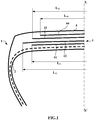
- the figure 1 only represents a half-view of a tire which is extended symmetrically with respect to the axis XX 'which represents the circumferential median plane, or equatorial plane, of the tire.
- the tire 1, of dimension 315/80 R 22.5 comprises a radial carcass reinforcement 2 anchored in two beads, not shown in the figure.
- the carcass reinforcement 2 is formed from a single layer of metal cables. They still have a tread 5.
- the reinforcing elements of the two working layers are metallic cables of formula 9.30, of the UHT type having a diameter equal to 1.23 mm. They are distributed in each of the working layers with a pitch P equal to 2 mm.
- the wires constituting the metallic cables have a mechanical tensile strength R equal to 3556 MPa and therefore satisfy the relationship R ⁇ 4180 - 2130xD.
- the figure 2 illustrates a partial view of part of the crown reinforcement in a meridian section of the tire.
- the thickness E 1 of the elastomeric mixtures measured radially between the reinforcing elements 431 of the radially outermost second working crown layer 43 and the reinforcing elements 441 of the protective layer 44 is equal to 1.39 mm.
- the ratio E 1 / P is equal to 0.70 and therefore in accordance with the invention strictly greater than 0.56.
- the thickness E 2 of the elastomeric mixtures measured radially between the reinforcing elements 431 of the second working crown layer 43 radially the outermost and the reinforcing elements 421 of the first working crown layer 42 is equal to 0.78 mm.
- the E 2 / P ratio is equal to 0.39 and therefore in accordance with the invention strictly greater than 0.30.
- the ratio E1 / E2 is equal to 1.78 and therefore in accordance with the invention strictly less than 1.8.
- the cumulative mass of the working layers, of the protective layer and of the triangulation layer of the reference tire, including the mass of the metallic cables and calendering mixtures, amounts to 11.2 kg.
- the tire according to the invention is compared with a reference tire of the same dimension which differs from the tire according to the invention by metallic cables of the two working layers which are cables of formula 11.35 of the SHT type, having a diameter equal to 1.48 mm. . They are distributed in each of the working layers with a pitch equal to 2.6 mm.
- the thickness E 1 of the elastomeric mixtures measured between the reinforcing elements of the second radially outermost working crown layer and the reinforcing elements of the protective layer of the reference tire is equal to 1.4 mm.
- the ratio E 1 / P is equal to 0.54.
- the thickness E 2 of the elastomeric mixtures measured between the reinforcing elements of the second radially outermost working crown layer and the reinforcing elements of the first working crown layer of the reference tire is equal to 0.8 mm.
- the ratio E 2 / P is equal to 0.31.
- the cumulative mass of the working layers, the protective layer and the triangulation layer of the reference tire, including the mass of the metallic cables and calendering mixtures, amounts to 12.7 kg.
- the first endurance tests were carried out on a test machine requiring each tire to run in a straight line at a speed equal to the maximum speed index prescribed for said tire (speed index) under an initial load of 4000 kg progressively increased to reduce test time.
- Tests aimed at characterizing the breaking strength of a tire crown reinforcement subjected to impacts have also been carried out. These tests consist of driving cylindrical polars into the tread of the inflated tire to a recommended pressure. The values express the energy necessary to obtain the rupture of the top block. The values are expressed from a base 100 corresponding to the value measured for the reference tire.
Landscapes
- Engineering & Computer Science (AREA)
- Mechanical Engineering (AREA)
- Tires In General (AREA)
- Ropes Or Cables (AREA)
Claims (10)
- Reifen (1) für ein Fahrzeug vom Typ Lastkraftwagen mit radialer Karkassenbewehrung (2), umfassend eine Scheitelbewehrung (4), die ausgebildet ist aus zumindest zwei Arbeitsscheitelschichten von Verstärkungselementen (42, 43), wobei die Verstärkungselemente der radial äußersten Arbeitsscheitelschicht (43) mit einem Abstand P verteilt sind, und aus zumindest einer Schutzschicht von Verstärkungselementen (44) radial außerhalb der zumindest zwei Arbeitsscheitelschichten (42, 43), wobei die Verstärkungselemente der Schutzschicht (44) relativ zur Umfangsrichtung mit einem Winkel zwischen 10° und 45° und von derselben Richtung wie der Winkel, der durch die Verstärkungselemente der ihr radial am nächsten liegenden Arbeitsschicht (43) ausgebildet ist, ausgerichtet sind, die ihrerseits radial von einem Laufstreifen (5) bedeckt ist, wobei der Laufstreifen (5) über zwei Seitenwände mit zwei Wülsten verbunden ist, wobei die Verstärkungselemente (431) der radial äußersten Arbeitsscheitelschicht (43) von den Verstärkungselementen (441) der Schutzschicht (44), die der radial äußersten Arbeitsscheitelschicht (43) radial am nächsten ist, durch Elastomermischungen radial getrennt sind, deren Dicke E1 mehr als 1 mm beträgt, und von den Verstärkungselementen (421) der Arbeitsscheitelschicht (42), die der radial äußersten Arbeitsscheitelschicht (43) radial am nächsten ist, durch Elastomermischungen mit einer Dicke E2 radial getrennt sind,
wobei die Verstärkungselemente (421, 431) der Arbeitsscheitelschichten (42, 43) Metallseile sind, von denen mindestens ein Draht jedes Metallseils mindestens einer Arbeitsscheitelschicht zumindest vom UHT-Grad ist,
wobei das Verhältnis der Dicke E1 von Elastomermischungen zwischen den Verstärkungselementen (431) der radial äußersten Arbeitsscheitelschicht (43) und den Verstärkungselementen (441) der Schutzschicht (44), die der radial äußersten Arbeitsscheitelschicht (43) radial am nächsten ist, zum Verteilungsabstand P der Verstärkungselemente (431) in der radial äußersten Arbeitsscheitelschicht (43), E1/P, streng größer als 0,56 ist,
wobei das Verhältnis der Dicke E2 von Elastomermischungen zwischen den Verstärkungselementen (431) der radial äußersten Arbeitsscheitelschicht (43) und den Verstärkungselementen (421) der Arbeitsscheitelschicht (42), die der radial äußersten Arbeitsscheitelschicht (43) radial am nächsten ist, zum Verteilungsabstand P der Verstärkungselemente (431) in der radial äußersten Arbeitsscheitelschicht (43), E2/P, streng größer als 0,30 ist,
dadurch gekennzeichnet, dass die Verstärkungselemente (421, 431) der Arbeitsscheitelschichten (42, 43) Metallseile mit einem Durchmesser von weniger als 1,3 mm sind, und dadurch, dass das Verhältnis der Dicke E1 von Elastomermischungen zwischen den Verstärkungselementen (431) der radial äußersten Arbeitsscheitelschicht (43) und den Verstärkungselementen (441) der Schutzschicht (44), die der radial äußersten Arbeitsscheitelschicht (43) radial am nächsten ist, zur Dicke E2 von Elastomermischungen zwischen den Verstärkungselementen (431) der radial äußersten Arbeitsscheitelschicht (43) und den Verstärkungselementen (421) der Arbeitsscheitelschicht (42), die der radial äußersten Arbeitsscheitelschicht radial am nächsten ist, E1/E2, streng kleiner als 1,8 ist. - Reifen (1) nach Anspruch 1, dadurch gekennzeichnet, dass er dazu bestimmt ist, auf Räder mit einem Sitzdurchmesser von 20 Zoll oder mehr montiert zu werden.
- Reifen (1) nach Anspruch 1 oder 2, dadurch gekennzeichnet, dass die Verstärkungselemente (421, 431) zumindest einer Arbeitsscheitelschicht (42, 43) Seile sind, die eine innere Schicht aus M inneren Drähten und eine äußere Schicht aus N äußeren Drähten umfassen, wobei die äußere Schicht um die innere Schicht gewickelt ist.
- Reifen (1) nach Anspruch 3, dadurch gekennzeichnet, dass M = 1 und N = 5 oder 6 oder M = 2 und N = 7, 8 oder 9.
- Reifen (1) nach einem der Ansprüche 3 oder 4, dadurch gekennzeichnet, dass die Verstärkungselemente (421, 431) der Arbeitsscheitelschichten (42, 43) Seile sind, die eine innere Schicht aus M inneren Drähten und eine äußere Schicht aus N äußeren Drähten umfassen, wobei die äußere Schicht um die innere Schicht gewickelt ist, wobei M = 1 oder 2 und N = 5, 6, 7, 8, wobei zumindest einer der inneren oder äußeren Drähte jedes Seils und vorzugsweise jeder innere und äußere Draht jedes Seils eine solche mechanische Bruchfestigkeit R, ausgedrückt in MPa, aufweist, dass R ≥ 4180 - 2130 x D ist, wobei D der Durchmesser des Drahtes, ausgedrückt in mm, ist.
- Reifen nach einem der Ansprüche 3 bis 5, dadurch gekennzeichnet, dass die Verstärkungselemente (421, 431) der zumindest zwei Arbeitsschichten (42, 43) Seile sind, die eine innere Schicht aus M inneren Drähten und eine äußere Schicht aus N äußeren Drähten umfassen, wobei die äußere Schicht um die innere Schicht gewickelt ist, wobei M = 1 oder 2 und N = 5, 6, 7, 8, wobei zumindest einer der inneren oder äußeren Drähte jedes Seils und vorzugsweise jeder innere und äußere Draht jedes Seils eine solche mechanische Bruchfestigkeit R, ausgedrückt in MPa, aufweist, dass R ≥ 4400 - 2000 x D ist, wobei D der Durchmesser des Drahtes, ausgedrückt in mm, ist.
- Reifen (1) nach einem der vorhergehenden Ansprüche, dadurch gekennzeichnet, dass sich die Verstärkungselemente (421, 431) der zumindest zwei Arbeitsscheitelschichten (42, 43) von einer Schicht zur anderen überkreuzen und dabei mit der Umfangsrichtung Winkel zwischen 10° und 45° ausbilden.
- Reifen (1) nach einem der vorhergehenden Ansprüche, dadurch gekennzeichnet, dass die Verstärkungselemente der mindestens zwei Arbeitsscheitelschichten (42, 43) nicht dehnbare Metallseile sind.
- Reifen (1) nach einem der vorhergehenden Ansprüche, dadurch gekennzeichnet, dass die Verstärkungselemente (441) der zumindest einen Schutzschicht (44) elastische Metallseile sind.
- Reifen (1) nach einem der vorhergehenden Ansprüche, dadurch gekennzeichnet, dass die Scheitelbewehrung (4) außerdem eine Triangulationsschicht (41) aufweist, die aus metallischen Verstärkungselementen ausgebildet ist, die mit der Umfangsrichtung Winkel von mehr als 45° bilden.
Applications Claiming Priority (2)
| Application Number | Priority Date | Filing Date | Title |
|---|---|---|---|
| FR1662053 | 2016-12-07 | ||
| PCT/FR2017/053427 WO2018104668A1 (fr) | 2016-12-07 | 2017-12-07 | Pneumatique comportant une armature de sommet allegee |
Publications (2)
| Publication Number | Publication Date |
|---|---|
| EP3551473A1 EP3551473A1 (de) | 2019-10-16 |
| EP3551473B1 true EP3551473B1 (de) | 2021-04-28 |
Family
ID=58054281
Family Applications (1)
| Application Number | Title | Priority Date | Filing Date |
|---|---|---|---|
| EP17821692.5A Active EP3551473B1 (de) | 2016-12-07 | 2017-12-07 | Reifen mit einer erleichterten kronenverstärkung |
Country Status (2)
| Country | Link |
|---|---|
| EP (1) | EP3551473B1 (de) |
| WO (1) | WO2018104668A1 (de) |
Family Cites Families (7)
| Publication number | Priority date | Publication date | Assignee | Title |
|---|---|---|---|---|
| NL300727A (de) | 1962-12-05 | |||
| NL6717027A (de) * | 1967-02-08 | 1968-08-09 | ||
| JP3045732B2 (ja) * | 1989-05-22 | 2000-05-29 | 株式会社ブリヂストン | ラジアルタイヤ |
| EP0551124B1 (de) * | 1992-01-09 | 1998-05-20 | Bridgestone Corporation | Stahlseil |
| FR2728510A1 (fr) | 1994-12-23 | 1996-06-28 | Michelin & Cie | Pneumatique de rapport de forme h/s inferieur ou egal a 0,6 |
| FR2770458B1 (fr) | 1997-11-05 | 1999-12-03 | Michelin & Cie | Armature de sommet pour pneumatique "poids-lours" |
| DE102014224497A1 (de) * | 2014-12-01 | 2016-06-02 | Continental Reifen Deutschland Gmbh | Nutzfahrzeugreifen mit Gürtel |
-
2017
- 2017-12-07 EP EP17821692.5A patent/EP3551473B1/de active Active
- 2017-12-07 WO PCT/FR2017/053427 patent/WO2018104668A1/fr not_active Ceased
Also Published As
| Publication number | Publication date |
|---|---|
| CA3042115A1 (fr) | 2018-06-14 |
| WO2018104668A1 (fr) | 2018-06-14 |
| EP3551473A1 (de) | 2019-10-16 |
Similar Documents
| Publication | Publication Date | Title |
|---|---|---|
| EP3423293B1 (de) | Gürtels eines luftreifens bestehend aus zwei geneigten gürtellagen und einer lage aus die umfangsrichtung umlaufenden verstärkungselementen | |
| EP3423292B1 (de) | Reifenkronenverstärkung aus zwei arbeitskronenschichten | |
| EP3423291B1 (de) | Reifenkronenverstärkung aus zwei arbeitskronenschichten | |
| EP3512720B1 (de) | Reifen mit drei arbeitsschichten | |
| EP3551472B1 (de) | Luftreifen mit leichterer gürtelverstärkung | |
| EP3317125B1 (de) | Reifen mit drei arbeitsschichten | |
| EP3946972B1 (de) | Reifenkronenverstärkung aus zwei arbeitskronenschichten | |
| EP3746313B1 (de) | Reifen mit drei arbeitsschichten | |
| EP3551473B1 (de) | Reifen mit einer erleichterten kronenverstärkung | |
| EP3980283B1 (de) | Reifen mit einer scheitelverstärkung, bestehend aus zwei arbeitsgürtel-scheitellagen und optimierten seitenwänden | |
| FR3064213B1 (fr) | Armature de sommet de pneumatique constituee d'une couche de sommet de travail et d'une couche d'elements circonferentiels | |
| EP3946971B1 (de) | Aus zwei arbeitenden gürtelschichten und einer schicht aus umlaufenden verstärkungselementen zusammengesetzte reifengürtelverstärkung | |
| CA3014453C (fr) | Armature de sommet de pneumatique constituee de deux couches de sommet de travail | |
| CA3042115C (fr) | Pneumatique comportant une armature de sommet allegee | |
| CA3014493C (fr) | Armature de sommet de pneumatique constituee de deux couches de sommet de travail et d'une couche d'elements de renforcement circonferentiels | |
| CA3041941C (fr) | Pneumatique comportant une armature de sommet allegee | |
| EP4065384A1 (de) | Luftreifen-bodenverstärkung, bestehend aus zwei arbeits-bodenlagen und einer lage aus umlaufenden verstärkungselementen |
Legal Events
| Date | Code | Title | Description |
|---|---|---|---|
| STAA | Information on the status of an ep patent application or granted ep patent |
Free format text: STATUS: UNKNOWN |
|
| STAA | Information on the status of an ep patent application or granted ep patent |
Free format text: STATUS: THE INTERNATIONAL PUBLICATION HAS BEEN MADE |
|
| PUAI | Public reference made under article 153(3) epc to a published international application that has entered the european phase |
Free format text: ORIGINAL CODE: 0009012 |
|
| STAA | Information on the status of an ep patent application or granted ep patent |
Free format text: STATUS: REQUEST FOR EXAMINATION WAS MADE |
|
| 17P | Request for examination filed |
Effective date: 20190708 |
|
| AK | Designated contracting states |
Kind code of ref document: A1 Designated state(s): AL AT BE BG CH CY CZ DE DK EE ES FI FR GB GR HR HU IE IS IT LI LT LU LV MC MK MT NL NO PL PT RO RS SE SI SK SM TR |
|
| AX | Request for extension of the european patent |
Extension state: BA ME |
|
| DAV | Request for validation of the european patent (deleted) | ||
| DAX | Request for extension of the european patent (deleted) | ||
| GRAP | Despatch of communication of intention to grant a patent |
Free format text: ORIGINAL CODE: EPIDOSNIGR1 |
|
| STAA | Information on the status of an ep patent application or granted ep patent |
Free format text: STATUS: GRANT OF PATENT IS INTENDED |
|
| INTG | Intention to grant announced |
Effective date: 20201215 |
|
| GRAS | Grant fee paid |
Free format text: ORIGINAL CODE: EPIDOSNIGR3 |
|
| GRAA | (expected) grant |
Free format text: ORIGINAL CODE: 0009210 |
|
| STAA | Information on the status of an ep patent application or granted ep patent |
Free format text: STATUS: THE PATENT HAS BEEN GRANTED |
|
| AK | Designated contracting states |
Kind code of ref document: B1 Designated state(s): AL AT BE BG CH CY CZ DE DK EE ES FI FR GB GR HR HU IE IS IT LI LT LU LV MC MK MT NL NO PL PT RO RS SE SI SK SM TR |
|
| REG | Reference to a national code |
Ref country code: GB Ref legal event code: FG4D Free format text: NOT ENGLISH |
|
| REG | Reference to a national code |
Ref country code: CH Ref legal event code: EP |
|
| REG | Reference to a national code |
Ref country code: AT Ref legal event code: REF Ref document number: 1386670 Country of ref document: AT Kind code of ref document: T Effective date: 20210515 |
|
| REG | Reference to a national code |
Ref country code: DE Ref legal event code: R096 Ref document number: 602017037753 Country of ref document: DE |
|
| REG | Reference to a national code |
Ref country code: IE Ref legal event code: FG4D Free format text: LANGUAGE OF EP DOCUMENT: FRENCH |
|
| REG | Reference to a national code |
Ref country code: LT Ref legal event code: MG9D |
|
| REG | Reference to a national code |
Ref country code: AT Ref legal event code: MK05 Ref document number: 1386670 Country of ref document: AT Kind code of ref document: T Effective date: 20210428 |
|
| PG25 | Lapsed in a contracting state [announced via postgrant information from national office to epo] |
Ref country code: NL Free format text: LAPSE BECAUSE OF FAILURE TO SUBMIT A TRANSLATION OF THE DESCRIPTION OR TO PAY THE FEE WITHIN THE PRESCRIBED TIME-LIMIT Effective date: 20210428 Ref country code: HR Free format text: LAPSE BECAUSE OF FAILURE TO SUBMIT A TRANSLATION OF THE DESCRIPTION OR TO PAY THE FEE WITHIN THE PRESCRIBED TIME-LIMIT Effective date: 20210428 Ref country code: AT Free format text: LAPSE BECAUSE OF FAILURE TO SUBMIT A TRANSLATION OF THE DESCRIPTION OR TO PAY THE FEE WITHIN THE PRESCRIBED TIME-LIMIT Effective date: 20210428 Ref country code: BG Free format text: LAPSE BECAUSE OF FAILURE TO SUBMIT A TRANSLATION OF THE DESCRIPTION OR TO PAY THE FEE WITHIN THE PRESCRIBED TIME-LIMIT Effective date: 20210728 Ref country code: LT Free format text: LAPSE BECAUSE OF FAILURE TO SUBMIT A TRANSLATION OF THE DESCRIPTION OR TO PAY THE FEE WITHIN THE PRESCRIBED TIME-LIMIT Effective date: 20210428 Ref country code: FI Free format text: LAPSE BECAUSE OF FAILURE TO SUBMIT A TRANSLATION OF THE DESCRIPTION OR TO PAY THE FEE WITHIN THE PRESCRIBED TIME-LIMIT Effective date: 20210428 |
|
| PG25 | Lapsed in a contracting state [announced via postgrant information from national office to epo] |
Ref country code: GR Free format text: LAPSE BECAUSE OF FAILURE TO SUBMIT A TRANSLATION OF THE DESCRIPTION OR TO PAY THE FEE WITHIN THE PRESCRIBED TIME-LIMIT Effective date: 20210729 Ref country code: IS Free format text: LAPSE BECAUSE OF FAILURE TO SUBMIT A TRANSLATION OF THE DESCRIPTION OR TO PAY THE FEE WITHIN THE PRESCRIBED TIME-LIMIT Effective date: 20210828 Ref country code: RS Free format text: LAPSE BECAUSE OF FAILURE TO SUBMIT A TRANSLATION OF THE DESCRIPTION OR TO PAY THE FEE WITHIN THE PRESCRIBED TIME-LIMIT Effective date: 20210428 Ref country code: SE Free format text: LAPSE BECAUSE OF FAILURE TO SUBMIT A TRANSLATION OF THE DESCRIPTION OR TO PAY THE FEE WITHIN THE PRESCRIBED TIME-LIMIT Effective date: 20210428 Ref country code: NO Free format text: LAPSE BECAUSE OF FAILURE TO SUBMIT A TRANSLATION OF THE DESCRIPTION OR TO PAY THE FEE WITHIN THE PRESCRIBED TIME-LIMIT Effective date: 20210728 Ref country code: PT Free format text: LAPSE BECAUSE OF FAILURE TO SUBMIT A TRANSLATION OF THE DESCRIPTION OR TO PAY THE FEE WITHIN THE PRESCRIBED TIME-LIMIT Effective date: 20210830 Ref country code: LV Free format text: LAPSE BECAUSE OF FAILURE TO SUBMIT A TRANSLATION OF THE DESCRIPTION OR TO PAY THE FEE WITHIN THE PRESCRIBED TIME-LIMIT Effective date: 20210428 Ref country code: PL Free format text: LAPSE BECAUSE OF FAILURE TO SUBMIT A TRANSLATION OF THE DESCRIPTION OR TO PAY THE FEE WITHIN THE PRESCRIBED TIME-LIMIT Effective date: 20210428 |
|
| REG | Reference to a national code |
Ref country code: NL Ref legal event code: MP Effective date: 20210428 |
|
| PG25 | Lapsed in a contracting state [announced via postgrant information from national office to epo] |
Ref country code: ES Free format text: LAPSE BECAUSE OF FAILURE TO SUBMIT A TRANSLATION OF THE DESCRIPTION OR TO PAY THE FEE WITHIN THE PRESCRIBED TIME-LIMIT Effective date: 20210428 Ref country code: SK Free format text: LAPSE BECAUSE OF FAILURE TO SUBMIT A TRANSLATION OF THE DESCRIPTION OR TO PAY THE FEE WITHIN THE PRESCRIBED TIME-LIMIT Effective date: 20210428 Ref country code: SM Free format text: LAPSE BECAUSE OF FAILURE TO SUBMIT A TRANSLATION OF THE DESCRIPTION OR TO PAY THE FEE WITHIN THE PRESCRIBED TIME-LIMIT Effective date: 20210428 Ref country code: RO Free format text: LAPSE BECAUSE OF FAILURE TO SUBMIT A TRANSLATION OF THE DESCRIPTION OR TO PAY THE FEE WITHIN THE PRESCRIBED TIME-LIMIT Effective date: 20210428 Ref country code: CZ Free format text: LAPSE BECAUSE OF FAILURE TO SUBMIT A TRANSLATION OF THE DESCRIPTION OR TO PAY THE FEE WITHIN THE PRESCRIBED TIME-LIMIT Effective date: 20210428 Ref country code: DK Free format text: LAPSE BECAUSE OF FAILURE TO SUBMIT A TRANSLATION OF THE DESCRIPTION OR TO PAY THE FEE WITHIN THE PRESCRIBED TIME-LIMIT Effective date: 20210428 Ref country code: EE Free format text: LAPSE BECAUSE OF FAILURE TO SUBMIT A TRANSLATION OF THE DESCRIPTION OR TO PAY THE FEE WITHIN THE PRESCRIBED TIME-LIMIT Effective date: 20210428 |
|
| REG | Reference to a national code |
Ref country code: DE Ref legal event code: R097 Ref document number: 602017037753 Country of ref document: DE |
|
| PLBE | No opposition filed within time limit |
Free format text: ORIGINAL CODE: 0009261 |
|
| STAA | Information on the status of an ep patent application or granted ep patent |
Free format text: STATUS: NO OPPOSITION FILED WITHIN TIME LIMIT |
|
| 26N | No opposition filed |
Effective date: 20220131 |
|
| PG25 | Lapsed in a contracting state [announced via postgrant information from national office to epo] |
Ref country code: IS Free format text: LAPSE BECAUSE OF FAILURE TO SUBMIT A TRANSLATION OF THE DESCRIPTION OR TO PAY THE FEE WITHIN THE PRESCRIBED TIME-LIMIT Effective date: 20210828 Ref country code: AL Free format text: LAPSE BECAUSE OF FAILURE TO SUBMIT A TRANSLATION OF THE DESCRIPTION OR TO PAY THE FEE WITHIN THE PRESCRIBED TIME-LIMIT Effective date: 20210428 |
|
| PG25 | Lapsed in a contracting state [announced via postgrant information from national office to epo] |
Ref country code: MC Free format text: LAPSE BECAUSE OF FAILURE TO SUBMIT A TRANSLATION OF THE DESCRIPTION OR TO PAY THE FEE WITHIN THE PRESCRIBED TIME-LIMIT Effective date: 20210428 Ref country code: IT Free format text: LAPSE BECAUSE OF FAILURE TO SUBMIT A TRANSLATION OF THE DESCRIPTION OR TO PAY THE FEE WITHIN THE PRESCRIBED TIME-LIMIT Effective date: 20210428 |
|
| REG | Reference to a national code |
Ref country code: CH Ref legal event code: PL |
|
| GBPC | Gb: european patent ceased through non-payment of renewal fee |
Effective date: 20211207 |
|
| REG | Reference to a national code |
Ref country code: BE Ref legal event code: MM Effective date: 20211231 |
|
| PG25 | Lapsed in a contracting state [announced via postgrant information from national office to epo] |
Ref country code: LU Free format text: LAPSE BECAUSE OF NON-PAYMENT OF DUE FEES Effective date: 20211207 Ref country code: IE Free format text: LAPSE BECAUSE OF NON-PAYMENT OF DUE FEES Effective date: 20211207 Ref country code: GB Free format text: LAPSE BECAUSE OF NON-PAYMENT OF DUE FEES Effective date: 20211207 |
|
| PG25 | Lapsed in a contracting state [announced via postgrant information from national office to epo] |
Ref country code: BE Free format text: LAPSE BECAUSE OF NON-PAYMENT OF DUE FEES Effective date: 20211231 |
|
| PG25 | Lapsed in a contracting state [announced via postgrant information from national office to epo] |
Ref country code: LI Free format text: LAPSE BECAUSE OF NON-PAYMENT OF DUE FEES Effective date: 20211231 Ref country code: CH Free format text: LAPSE BECAUSE OF NON-PAYMENT OF DUE FEES Effective date: 20211231 |
|
| PG25 | Lapsed in a contracting state [announced via postgrant information from national office to epo] |
Ref country code: CY Free format text: LAPSE BECAUSE OF FAILURE TO SUBMIT A TRANSLATION OF THE DESCRIPTION OR TO PAY THE FEE WITHIN THE PRESCRIBED TIME-LIMIT Effective date: 20210428 |
|
| PG25 | Lapsed in a contracting state [announced via postgrant information from national office to epo] |
Ref country code: HU Free format text: LAPSE BECAUSE OF FAILURE TO SUBMIT A TRANSLATION OF THE DESCRIPTION OR TO PAY THE FEE WITHIN THE PRESCRIBED TIME-LIMIT; INVALID AB INITIO Effective date: 20171207 |
|
| PG25 | Lapsed in a contracting state [announced via postgrant information from national office to epo] |
Ref country code: MK Free format text: LAPSE BECAUSE OF FAILURE TO SUBMIT A TRANSLATION OF THE DESCRIPTION OR TO PAY THE FEE WITHIN THE PRESCRIBED TIME-LIMIT Effective date: 20210428 |
|
| PG25 | Lapsed in a contracting state [announced via postgrant information from national office to epo] |
Ref country code: TR Free format text: LAPSE BECAUSE OF FAILURE TO SUBMIT A TRANSLATION OF THE DESCRIPTION OR TO PAY THE FEE WITHIN THE PRESCRIBED TIME-LIMIT Effective date: 20210428 |
|
| PG25 | Lapsed in a contracting state [announced via postgrant information from national office to epo] |
Ref country code: MT Free format text: LAPSE BECAUSE OF FAILURE TO SUBMIT A TRANSLATION OF THE DESCRIPTION OR TO PAY THE FEE WITHIN THE PRESCRIBED TIME-LIMIT Effective date: 20210428 |
|
| PGFP | Annual fee paid to national office [announced via postgrant information from national office to epo] |
Ref country code: DE Payment date: 20251211 Year of fee payment: 9 |
|
| PGFP | Annual fee paid to national office [announced via postgrant information from national office to epo] |
Ref country code: FR Payment date: 20251229 Year of fee payment: 9 |