EP3551429B1 - Color representation of a property of a 3d object - Google Patents
Color representation of a property of a 3d object Download PDFInfo
- Publication number
- EP3551429B1 EP3551429B1 EP17908061.9A EP17908061A EP3551429B1 EP 3551429 B1 EP3551429 B1 EP 3551429B1 EP 17908061 A EP17908061 A EP 17908061A EP 3551429 B1 EP3551429 B1 EP 3551429B1
- Authority
- EP
- European Patent Office
- Prior art keywords
- color
- examples
- material property
- color material
- dispenser
- Prior art date
- Legal status (The legal status is an assumption and is not a legal conclusion. Google has not performed a legal analysis and makes no representation as to the accuracy of the status listed.)
- Active
Links
- 239000000463 material Substances 0.000 claims description 336
- 239000012530 fluid Substances 0.000 claims description 131
- 239000003795 chemical substances by application Substances 0.000 claims description 96
- 238000004519 manufacturing process Methods 0.000 claims description 48
- 239000003086 colorant Substances 0.000 claims description 34
- 238000013507 mapping Methods 0.000 claims description 23
- 238000000034 method Methods 0.000 claims description 23
- 239000000126 substance Substances 0.000 claims description 15
- 230000001747 exhibiting effect Effects 0.000 claims description 12
- 230000006870 function Effects 0.000 description 57
- 238000010586 diagram Methods 0.000 description 29
- 239000000654 additive Substances 0.000 description 14
- 230000000996 additive effect Effects 0.000 description 13
- 230000015654 memory Effects 0.000 description 10
- 238000010276 construction Methods 0.000 description 9
- 239000000203 mixture Substances 0.000 description 6
- 238000004458 analytical method Methods 0.000 description 5
- 230000015572 biosynthetic process Effects 0.000 description 5
- 230000008859 change Effects 0.000 description 5
- 238000004891 communication Methods 0.000 description 5
- 238000009826 distribution Methods 0.000 description 4
- 238000007639 printing Methods 0.000 description 4
- 230000009471 action Effects 0.000 description 3
- 239000011248 coating agent Substances 0.000 description 3
- 238000000576 coating method Methods 0.000 description 3
- 230000000295 complement effect Effects 0.000 description 3
- 238000013461 design Methods 0.000 description 3
- 230000007246 mechanism Effects 0.000 description 3
- 238000002844 melting Methods 0.000 description 3
- 230000008018 melting Effects 0.000 description 3
- 239000002861 polymer material Substances 0.000 description 3
- 238000003860 storage Methods 0.000 description 3
- 230000007704 transition Effects 0.000 description 3
- 239000011230 binding agent Substances 0.000 description 2
- 238000000151 deposition Methods 0.000 description 2
- 238000005516 engineering process Methods 0.000 description 2
- 239000006260 foam Substances 0.000 description 2
- 239000007788 liquid Substances 0.000 description 2
- 230000003287 optical effect Effects 0.000 description 2
- 239000000843 powder Substances 0.000 description 2
- 230000008569 process Effects 0.000 description 2
- 238000012545 processing Methods 0.000 description 2
- 238000000110 selective laser sintering Methods 0.000 description 2
- 238000005245 sintering Methods 0.000 description 2
- 238000006467 substitution reaction Methods 0.000 description 2
- 230000000007 visual effect Effects 0.000 description 2
- 238000010146 3D printing Methods 0.000 description 1
- 241000295146 Gallionellaceae Species 0.000 description 1
- 241000282412 Homo Species 0.000 description 1
- 239000004952 Polyamide Substances 0.000 description 1
- 230000004913 activation Effects 0.000 description 1
- 239000000443 aerosol Substances 0.000 description 1
- 239000000919 ceramic Substances 0.000 description 1
- 229910010293 ceramic material Inorganic materials 0.000 description 1
- 230000007797 corrosion Effects 0.000 description 1
- 238000005260 corrosion Methods 0.000 description 1
- 230000003247 decreasing effect Effects 0.000 description 1
- 230000008021 deposition Effects 0.000 description 1
- 230000004907 flux Effects 0.000 description 1
- 230000004927 fusion Effects 0.000 description 1
- 230000014509 gene expression Effects 0.000 description 1
- 229910052736 halogen Inorganic materials 0.000 description 1
- 150000002367 halogens Chemical class 0.000 description 1
- 238000010438 heat treatment Methods 0.000 description 1
- 230000001678 irradiating effect Effects 0.000 description 1
- 230000005012 migration Effects 0.000 description 1
- 238000013508 migration Methods 0.000 description 1
- 230000003278 mimic effect Effects 0.000 description 1
- 239000002245 particle Substances 0.000 description 1
- 230000002085 persistent effect Effects 0.000 description 1
- 229920002647 polyamide Polymers 0.000 description 1
- 229920000642 polymer Polymers 0.000 description 1
- 230000009257 reactivity Effects 0.000 description 1
- 230000004044 response Effects 0.000 description 1
- 239000007787 solid Substances 0.000 description 1
- 238000003892 spreading Methods 0.000 description 1
- 230000007480 spreading Effects 0.000 description 1
- 230000003068 static effect Effects 0.000 description 1
- 238000011179 visual inspection Methods 0.000 description 1
Images


Classifications
-
- B—PERFORMING OPERATIONS; TRANSPORTING
- B29—WORKING OF PLASTICS; WORKING OF SUBSTANCES IN A PLASTIC STATE IN GENERAL
- B29C—SHAPING OR JOINING OF PLASTICS; SHAPING OF MATERIAL IN A PLASTIC STATE, NOT OTHERWISE PROVIDED FOR; AFTER-TREATMENT OF THE SHAPED PRODUCTS, e.g. REPAIRING
- B29C64/00—Additive manufacturing, i.e. manufacturing of three-dimensional [3D] objects by additive deposition, additive agglomeration or additive layering, e.g. by 3D printing, stereolithography or selective laser sintering
- B29C64/30—Auxiliary operations or equipment
- B29C64/386—Data acquisition or data processing for additive manufacturing
- B29C64/393—Data acquisition or data processing for additive manufacturing for controlling or regulating additive manufacturing processes
-
- B—PERFORMING OPERATIONS; TRANSPORTING
- B29—WORKING OF PLASTICS; WORKING OF SUBSTANCES IN A PLASTIC STATE IN GENERAL
- B29C—SHAPING OR JOINING OF PLASTICS; SHAPING OF MATERIAL IN A PLASTIC STATE, NOT OTHERWISE PROVIDED FOR; AFTER-TREATMENT OF THE SHAPED PRODUCTS, e.g. REPAIRING
- B29C64/00—Additive manufacturing, i.e. manufacturing of three-dimensional [3D] objects by additive deposition, additive agglomeration or additive layering, e.g. by 3D printing, stereolithography or selective laser sintering
- B29C64/30—Auxiliary operations or equipment
- B29C64/307—Handling of material to be used in additive manufacturing
- B29C64/321—Feeding
- B29C64/336—Feeding of two or more materials
-
- B—PERFORMING OPERATIONS; TRANSPORTING
- B29—WORKING OF PLASTICS; WORKING OF SUBSTANCES IN A PLASTIC STATE IN GENERAL
- B29C—SHAPING OR JOINING OF PLASTICS; SHAPING OF MATERIAL IN A PLASTIC STATE, NOT OTHERWISE PROVIDED FOR; AFTER-TREATMENT OF THE SHAPED PRODUCTS, e.g. REPAIRING
- B29C64/00—Additive manufacturing, i.e. manufacturing of three-dimensional [3D] objects by additive deposition, additive agglomeration or additive layering, e.g. by 3D printing, stereolithography or selective laser sintering
- B29C64/10—Processes of additive manufacturing
- B29C64/106—Processes of additive manufacturing using only liquids or viscous materials, e.g. depositing a continuous bead of viscous material
- B29C64/112—Processes of additive manufacturing using only liquids or viscous materials, e.g. depositing a continuous bead of viscous material using individual droplets, e.g. from jetting heads
-
- B—PERFORMING OPERATIONS; TRANSPORTING
- B29—WORKING OF PLASTICS; WORKING OF SUBSTANCES IN A PLASTIC STATE IN GENERAL
- B29C—SHAPING OR JOINING OF PLASTICS; SHAPING OF MATERIAL IN A PLASTIC STATE, NOT OTHERWISE PROVIDED FOR; AFTER-TREATMENT OF THE SHAPED PRODUCTS, e.g. REPAIRING
- B29C64/00—Additive manufacturing, i.e. manufacturing of three-dimensional [3D] objects by additive deposition, additive agglomeration or additive layering, e.g. by 3D printing, stereolithography or selective laser sintering
- B29C64/10—Processes of additive manufacturing
- B29C64/188—Processes of additive manufacturing involving additional operations performed on the added layers, e.g. smoothing, grinding or thickness control
- B29C64/194—Processes of additive manufacturing involving additional operations performed on the added layers, e.g. smoothing, grinding or thickness control during lay-up
-
- B—PERFORMING OPERATIONS; TRANSPORTING
- B29—WORKING OF PLASTICS; WORKING OF SUBSTANCES IN A PLASTIC STATE IN GENERAL
- B29C—SHAPING OR JOINING OF PLASTICS; SHAPING OF MATERIAL IN A PLASTIC STATE, NOT OTHERWISE PROVIDED FOR; AFTER-TREATMENT OF THE SHAPED PRODUCTS, e.g. REPAIRING
- B29C64/00—Additive manufacturing, i.e. manufacturing of three-dimensional [3D] objects by additive deposition, additive agglomeration or additive layering, e.g. by 3D printing, stereolithography or selective laser sintering
- B29C64/20—Apparatus for additive manufacturing; Details thereof or accessories therefor
- B29C64/205—Means for applying layers
- B29C64/209—Heads; Nozzles
-
- B—PERFORMING OPERATIONS; TRANSPORTING
- B33—ADDITIVE MANUFACTURING TECHNOLOGY
- B33Y—ADDITIVE MANUFACTURING, i.e. MANUFACTURING OF THREE-DIMENSIONAL [3-D] OBJECTS BY ADDITIVE DEPOSITION, ADDITIVE AGGLOMERATION OR ADDITIVE LAYERING, e.g. BY 3-D PRINTING, STEREOLITHOGRAPHY OR SELECTIVE LASER SINTERING
- B33Y10/00—Processes of additive manufacturing
-
- B—PERFORMING OPERATIONS; TRANSPORTING
- B33—ADDITIVE MANUFACTURING TECHNOLOGY
- B33Y—ADDITIVE MANUFACTURING, i.e. MANUFACTURING OF THREE-DIMENSIONAL [3-D] OBJECTS BY ADDITIVE DEPOSITION, ADDITIVE AGGLOMERATION OR ADDITIVE LAYERING, e.g. BY 3-D PRINTING, STEREOLITHOGRAPHY OR SELECTIVE LASER SINTERING
- B33Y30/00—Apparatus for additive manufacturing; Details thereof or accessories therefor
-
- B—PERFORMING OPERATIONS; TRANSPORTING
- B33—ADDITIVE MANUFACTURING TECHNOLOGY
- B33Y—ADDITIVE MANUFACTURING, i.e. MANUFACTURING OF THREE-DIMENSIONAL [3-D] OBJECTS BY ADDITIVE DEPOSITION, ADDITIVE AGGLOMERATION OR ADDITIVE LAYERING, e.g. BY 3-D PRINTING, STEREOLITHOGRAPHY OR SELECTIVE LASER SINTERING
- B33Y50/00—Data acquisition or data processing for additive manufacturing
- B33Y50/02—Data acquisition or data processing for additive manufacturing for controlling or regulating additive manufacturing processes
-
- B—PERFORMING OPERATIONS; TRANSPORTING
- B29—WORKING OF PLASTICS; WORKING OF SUBSTANCES IN A PLASTIC STATE IN GENERAL
- B29C—SHAPING OR JOINING OF PLASTICS; SHAPING OF MATERIAL IN A PLASTIC STATE, NOT OTHERWISE PROVIDED FOR; AFTER-TREATMENT OF THE SHAPED PRODUCTS, e.g. REPAIRING
- B29C64/00—Additive manufacturing, i.e. manufacturing of three-dimensional [3D] objects by additive deposition, additive agglomeration or additive layering, e.g. by 3D printing, stereolithography or selective laser sintering
- B29C64/10—Processes of additive manufacturing
- B29C64/165—Processes of additive manufacturing using a combination of solid and fluid materials, e.g. a powder selectively bound by a liquid binder, catalyst, inhibitor or energy absorber
-
- B—PERFORMING OPERATIONS; TRANSPORTING
- B29—WORKING OF PLASTICS; WORKING OF SUBSTANCES IN A PLASTIC STATE IN GENERAL
- B29K—INDEXING SCHEME ASSOCIATED WITH SUBCLASSES B29B, B29C OR B29D, RELATING TO MOULDING MATERIALS OR TO MATERIALS FOR MOULDS, REINFORCEMENTS, FILLERS OR PREFORMED PARTS, e.g. INSERTS
- B29K2995/00—Properties of moulding materials, reinforcements, fillers, preformed parts or moulds
- B29K2995/0018—Properties of moulding materials, reinforcements, fillers, preformed parts or moulds having particular optical properties, e.g. fluorescent or phosphorescent
- B29K2995/002—Coloured
- B29K2995/0021—Multi-coloured
-
- Y—GENERAL TAGGING OF NEW TECHNOLOGICAL DEVELOPMENTS; GENERAL TAGGING OF CROSS-SECTIONAL TECHNOLOGIES SPANNING OVER SEVERAL SECTIONS OF THE IPC; TECHNICAL SUBJECTS COVERED BY FORMER USPC CROSS-REFERENCE ART COLLECTIONS [XRACs] AND DIGESTS
- Y02—TECHNOLOGIES OR APPLICATIONS FOR MITIGATION OR ADAPTATION AGAINST CLIMATE CHANGE
- Y02P—CLIMATE CHANGE MITIGATION TECHNOLOGIES IN THE PRODUCTION OR PROCESSING OF GOODS
- Y02P10/00—Technologies related to metal processing
- Y02P10/25—Process efficiency
Definitions
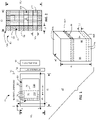
- the fluid dispenser 58 shown in FIG. 1 comprises a printing mechanism, such as an array of printheads, each including a plurality of individually addressable nozzles for selectively ejecting fluid agents onto a layer of build material. Accordingly, in some examples, the fluid dispenser 58 may sometimes be referred to as an addressable fluid ejection array. In some examples, the fluid dispenser 58 may eject individual droplets having a volume on the order of ones of picoliters or on the order of ones of nanoliters.
- fluid dispenser 58 may comprise, or be in fluid communication with, an array of reservoirs to contain various fluid agents 62.
- the array of reservoirs may comprise an ink supply 215, as shown in FIG. 3A .
- at least some of the fluid agents 62 may comprise a fusing agent, detailing agent, etc. to enhance formation of each layer 82A of build material.
- the respective fusing agent and/or detailing agent may diffuse, saturate, and/or blend into the respective layer of the build material at the selectable positions.
- the at least some selectable locations 72 may comprise selectable locations corresponding to an entire external surface of a 3D object or an entire component of a multi-component 3D object. In some examples, the at least some selected locations correspond to an entire region of a 3D object, such as but not limited to an end portion, middle, etc.
- FIG. 2 is an enlarged partial sectional view (e.g. a horizontal slice) which provides a further illustration of a portion of the example 3D object 80 in which a group 72 of exterior voxel locations 74 define the external surface 88 of 3D object 80 and a group 176 of interior voxel locations 177 define the interior 75 of a first portion 71A of the 3D object 80.
- each voxel location 74, 177 comprises a width W2 and length L2, which forms a portion of a width W3 and a length L3 of first portion 71A.
- the exterior voxel locations 74 exhibit an assigned first color on external surface 88 to represent at least a first non-color material property of the interior 75 of first portion 71A.
- a device 200 comprises at least substantially the same features and attributes as device 20 ( FIG. 1 ) except further comprising at least an energy source 210 for irradiating the deposited build materials, fluid agents (e.g. fusing agent), etc. to cause heating of the material, which in turn results in the fusing of particles of the material relative to each other, with such fusing occurring via melting, sintering, etc.
- a layer 82A e.g. FIG. 1
- additional layers 82A of build material may be formed in a similar manner as represented in FIG. 1 .
- device 20 manufactures 3D object 80 by forming a selectable number of layers 82A of a build material.
- This formation includes using material dispenser 50 to coat the build pad 42 (or a preceding layer 82A) with a layer 82A of the build material.
- a fluid agent 62 e.g. at least a fusing agent
- irradiation of these selectable portions by the energy source 210 results in fusing of the build material, fusing agents, detailing agents, etc.
- this cycle of coating, dispensing and fusing is repeated until a selected number of layers 82A of build material is formed into 3D object 80 as shown in at least FIG. 1 .
- the fluid dispenser 58 dispenses an assigned color at selectable exterior voxel locations 74 of at least some respective layers 82A, as shown in FIG. 1 .
- the assigned color(s) at these exterior voxel locations 74 will be visible upon completion of 3D object to enable recognition of the underlying non-color material property embodied in internal voxel locations (e.g. 177 in FIG. 2 ) of a 3D object.
- some of the selectable exterior voxel locations 74 may define the external surface 88 at sides 84 of 3D object 80.
- At least some selectable locations 74 at which an assigned first color may be dispensed may occur an uppermost layer of the 3D object which defines a top surface 86A ( FIG. 1 ) of the external surface 88 of the 3D object 80.
- the at least partially formed 3D object 80 comprises a first portion 71A and a second portion 71B with dashed line 73 representing a boundary between the first portion 71A.
- the first portion 71A corresponds to portions of the 3D object for which exterior voxel locations 74 are assigned a particular color to represent a particular non-color material property of the corresponding formed layer 82A of the 3D object at which the exterior voxel location is present.
- a 3D object with at least two different portions exhibiting different non-color material properties may sometimes be referred to as 3D object having a heterogeneous structure and the respective 3D color surface voxel representation (e.g. surface color map) may sometimes be referred to as exhibiting the heterogeneity material information.
- the at least some selectable voxel locations 74 are defined at any one of a top 86A, bottom 86B, sides 84 of the 3D object 80.
- at least some of the selectable voxel locations 74 may be contiguous over a transition between adjacent sides 84, from a bottom 86B to a side 84, etc. or any other change in orientation, angle, etc. which may present a discontinuity or change in surface topology.
- each of the various aspects described in association with at least FIGS. 4A-10 comprise at least some of substantially the same features and attributes as previously described for device 20, 200 in association with FIG. 1-3 .
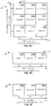
- FIG. 4A is a sectional view schematically representing an example 3D object 250.
- 3D object 250 may be formed via at least some of substantially the same features and attributes for additively manufacturing a 3D object (with an assigned 3D color surface voxel representation) as previously described in association with at least FIGS. 1-3 .
- 3D object 250 comprises a first portion 260 and a second portion 270.
- the first portion 260 comprises an interior portion 262 and exterior portion 264.
- the second portion 270 comprises an interior portion 272 and exterior portion 274.
- the exterior portion 264 of first portion 260 and the exterior portion 274 of second portion 270 define an external surface 288 for the entire 3D object 250.
- first portion 260 exhibits a first value of a first non-color material property
- interior portion 272 of second portion 270 exhibits a different second value of the same first non-color material property
- exterior portion 264 of first portion 260 exhibits the same value of the non-color material property as the interior portion 262
- exterior portion 274 of second portion 270 exhibits the same value of the non-color material property as interior portion 272.
- a first color is assigned and dispensed as a fluid agent at the group of first exterior voxel locations, which define exterior portion 264 of first portion 260, in order to represent a first value of the first non-color material property for the interior 262 of first portion 260.
- a second color is assigned and dispensed as a fluid agent at the group of second exterior voxel locations, which define exterior portion 274 of second portion 270, in order to represent a different, second value of the first non-color material property for the second portion 270 of the first 3D object.
- a selection of the respective first and second colors is independent of the characteristics of the respective first and second values of the first non-color material property.
- first color and the second color each may comprise a combination of different colors, such as but not limited to, when a given color (e.g. first color agent or second color agent) is defined in a RGB color space, CMYK color space etc.
- a given color e.g. first color agent or second color agent
- At least the interior portion 262 of first portion 260 exhibits a first non-color material property
- at least the interior portion 272 of second portion 270 exhibits a different second non-color material property.
- a first color is assigned and dispensed as a fluid agent at the group of first exterior voxel locations (which define portion 264 of first portion 260) in order to represent the first non-color material property for the interior 262 of first portion 260.
- a second color is assigned and dispensed as a fluid agent at the group of second voxel locations (which define exterior portion 274 of second portion 270) in order to represent a different, second non-color material property for the second portion 270 of the first 3D object.
- the selection of the respective first and second colors is independent of the characteristics of the respective first and second non-color material properties.
- the material dispenser 50 may build substantially the entire 3D object via layers using a single build material. As each layer is formed, the fluid dispenser 58 may dispense fluid agent(s) at interior voxel locations (e.g. 177 in FIG.
- first portion 260 of the 3D object may dispense different fluid agent(s) at interior voxel locations of the second portion 270 of the 3D object to produce the second non-color material property (or a second value of the first non-color material property) in the second portion of the 3D object.
- FIG. 4B is a table 300 schematically representing an example color map arranged in a sample format for illustrative simplicity.
- table 300 comprises one example implementation according to at least color mapping function 555 of at least color representation engine 540 of manufacturing engine 500 in FIG. 9 .
- table 300 demonstrates at least some aspects of color mapping for a 3D color surface voxel representation of a 3D object for a single non-color material property (MP-1).
- MP-1 non-color material property
- such color mapping establishes a one-to-one correspondence between assigned colors and the non-color material properties represented via such assigned colors.
- one voxel location for Group 1 has RGB values of (255, 0, 0) signifying a Red only color
- one voxel location for Group 2 has RGB values of (0, 0, 180) signifying a Blue only color.
- the Group 1 of voxel locations may correspond to the assignment of a first color (e.g. Red) to represent a first value of first non-color material property (e.g. MP-1) of interior voxel locations underlying the exterior voxel locations of Group 1.
- the Group 2 of voxel locations may correspond to the assignment of a different second color (e.g. Blue) to represent a second value of the same first non-color material property (e.g. MP-1) of interior voxel locations underlying the exterior voxel locations of Group 2.
- Rows 310A, 310B provide a similar example of a sample color mapping arrangement except with single voxel locations (1, 5, 10 and 1, 6, 10) instead of with groups of voxel locations.
- providing multiple assigned colors at a single exterior voxel location may be achieved via fluid dispenser 58 printing such multiple assigned colors independently and simultaneously at the selectable voxel location(s).
- fluid dispenser 58 printing such multiple assigned colors independently and simultaneously at the selectable voxel location(s).
- FIGS. 4D-4E are each a diagram schematically representing example color mapping.
- such color mapping may be used to implement at least some of the features and attributes of at least some of the examples previously described in association with at least FIGS. 1-3 and later described in association with at least FIGS. 5-10 .
- diagram 320 comprises an x-axis 324 and a y-axis 322, with the x-axis 324 representing a first material property (MP-1) and a first color channel (C-1) and with the y-axis 322 representing a second material property (MP-2) and a second color channel (C-2).
- first material property (MP-1) comprises a mechanical property, such as stress expressed in units of MegaPascals (MPa)
- MP-2 also comprises a mechanical property, such as elongation expressed in units of a percentage (%).
- some example values are provided for each of the respective first and second material properties.
- Diagram 320 also comprises a grid 325 expressing different colors assigned to a particular combination of the first and second material properties (MP-1, MP-2).
- Each block (e.g. 326A, 328B, etc.) within grid 325 represents a single color, which in turn is expressed via a particular combination of values of the first and second color channels, such as 0/255/0, 128/128/0, etc. in a R/G/B color space or other multi-dimensional color space.
- a single color may be expressed via three color channels (e.g. Red, Green, Blue or Cyan, Magenta, Yellow). While not shown explicitly in FIG. 4D , a single color may be expressed via four channels (e.g. Cyan, Magenta, Yellow, and Black). In later examples, a single color (representing a single non-color material property) may be expressed via a single color channel ( FIG. 4E ) or a single color (representing a non-color material property) may be expressed via at least two color channels ( FIG. 4F ).
- the first material property (MP-1) comprises stress
- the value of the first color channel (e.g. Red) increases from 0 to 255.
- the second material property (MP-2) comprises elongation
- the value of the second color channel (e.g. Green) increases from 0 to 255.
- this arrangement illustrates that a single color (e.g. the color represented via block 328B in grid 325) may simultaneously represent two non-color material properties (e.g. stress of 30 MPA and elongation of 20 %).
- the single color is expressed via two color channels (e.g. Red, Green) in a multi-dimensional color space (e.g. R/G/B).
- a single color (e.g. one of blocks 326A-329C in grid 325) may represent a combination of three different non-color material properties when the color space defines three color channels.
- a third axis would be further implemented such that grid 325 would comprise a three-dimensional grid of blocks with the third axis representing the third non-color material property.
- a single color (e.g. one of blocks 326A-329C in grid 325) may represent a combination of fourth different non-color material properties when the color space defines four color channels (e.g. C/M/Y/K).
- the values of the respective color channels in the grid 325 are representative and that values intermediate of those shown may be interpolated and/or expressed explicitly in a more comprehensive color map exhibiting a full range (e.g. O to 255) of numerical values of the color channels as they correspond to the values (of a full range) of the respective non-color material properties (represented by the respective colors in grid 325).
- FIG. 4E is a diagram 330 including a grid 335 schematically representing example color mapping.
- the color mapping represented via grid 335 comprises at least some of substantially the same features and attributes as previously described in association with at least FIG. 4D , except comprising a single color channel (C-1) mapped relative to a single non-color material property (MP-1) expressed along a single axis 334.
- different values of a single non-color material property (MP-1) may be represented via different colors (e.g. at blocks 336A, 336B, 336C) in which each different color is expressed via different values of a single color channel.
- FIG. 4F is a diagram 340 schematically representing example color mapping.
- the color mapping represented via diagram 340 comprises at least some of substantially the same features and attributes as previously described in association with at least FIG. 4D and/or 4E, except comprising two color channels (C-1, C-2) and a single non-color material property (MP-1).
- different values of a single non-color material property (MP-1) may be represented via different colors (e.g. at blocks 346A, 346B, 346C) in which each different color is expressed via two color channels (e.g. Red, Green) instead of via a single color channel ( FIG. 4E ).
- FIG. 5 is a diagram schematically representing a plurality of example 3D objects 382, 386 each including its own respective different 3D color surface color representation.
- 3D objects 382, 386 are formed via at least some of substantially the same features and attributes as previously described in association with at least FIGS. 1-4C .
- 3D object 382 comprises (at least) a first non-color material property and 3D object 386 comprises a different second non-color material property.
- the first 3D object 382 is formed from a first build material exhibiting the first non-color material property and the second 3D object 386 is formed from a different, second build material exhibiting the different second non-color material property.
- the respective different material properties may be achieved via applying fluid agent(s) to a single build material.
- an external surface 383 of first 3D object 382 comprises a first color (A) to represent a first non-color material property of the first 3D object while an external surface 387 of second 3D object comprises a second color (B) to represent a different, second non-color material property of the second 3D object 386.
- selection of the first and second colors is independent of characteristics of the respective first and second non-color material properties, where such characteristics may comprise intrinsic characteristics in some examples.
- each member of the family may exhibit different non-color material properties (or different values of the same non-color material property).
- a family of tools e.g. tweezers
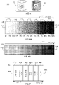
- FIG. 6A is a diagram schematically representing an example discrete color gradient representation 410 for at least a portion of an example 3D object.
- Representation 410 may be one implementation of a 3D color surface voxel representation which exhibits a monochromatic gradient and which may be specified via greyscale parameter (e.g. 552 in FIG. 9 ).
- greyscale parameter e.g. 552 in FIG. 9
- the gradient representation 410 may be expressed in full color via a color space parameter (e.g. 542 in FIG. 9 ) such as a RGB or CYMK color space, or other color spaces.
- each discrete portion 414 of the gradient representation 410 exhibits a different percentage of color with the percentage increasing in discrete steps (e.g. 5 or 10% in one example) from a first end 412A to an opposite second end 412B of the (color map) of the 3D object.
- these discrete steps in color change may facilitate human or machine vision recognition of a particular color which represents a particular portion of a 3D object and/or to readily distinguish different colors representing respective different portions of a 3D object which exhibit respectively different non-color material properties.
- the gradient representation may act as a color map when the values of a non-color material property (e.g. MP) or different non-color material properties are represented along a length of the gradient representation 410, as may be indicated in association with arrow 416.
- a non-color material property e.g. MP
- At least some aspects of the examples demonstrated via FIG. 6A are associated with and/or may comprise example implementations of at least the respective color, greyscale, discrete and gradient functions 541, 552, 546, 548 of the color representation engine 540 later described in association with at least FIG. 9 .
- a threshold is established (e.g. via discrete parameter 546 in FIG. 9 ) to ensure the adjacent discrete portions (e.g. 414) have differences in color which are of a sufficient magnitude to ensure their unique recognition relative to each other, as well as a well-defined boundary between the adjacent discrete portions.
- FIG. 6B is a diagram schematically representing an example continuous color gradient representation 430 for at least a portion of an example 3D object.
- the gradient representation 430 of FIG. 6B comprises at least some of substantially the same features and attributes as the discrete color gradient representation 410 in FIG. 6A .
- the change in color e.g. monochromatic in a greyscale example
- the change in color may be continuous instead of discrete.
- At least some aspects of the example implementations of FIG. 6B are associated with and/or may comprise an example implementation of the respective color, greyscale, continuous and gradient functions 541, 552, 547, and 548 of the color representation engine 540 later described in association with at least FIG. 9 .
- the gradient representations of FIGS. 6A, 6B may be appropriate when a value of a single non-color material property varies in an increasing manner, or in a decreasing manner, from a first end to an opposite second end of a 3D object. Such arrangements may enable quick visual recognition of a material property distribution throughout a 3D object.
- FIG. 7 is a diagram schematically represents an example non-gradient discrete color representation 440 (for at least a portion of an example 3D object), which may comprise one example implementation of a color 3D surface voxel representation.
- the non-gradient color representation 440 may be expressed in full color via a color space such as RGB or CYMK, as represented by the named colors (e.g. RED ONE, RED-ORANGE, etc.) in the respectively different discrete portions 442A-442F in FIG. 7 .
- these discrete steps in color change may facilitate human or machine vision recognition of a particular assigned color for a particular portion of a 3D object and/or to distinguish different assigned colors for different portions of a 3D object which exhibit respectively different non-color material properties (which may be mapped along arrow 416).
- the discrete non-gradient color representation 440 may be expressed monochromatically (instead of in full color) in which each discrete portion 442A-442F between opposite ends 444A, 444B may exhibit a different greyscale value.
- a threshold is established (e.g. via discrete parameter 546 in FIG. 9 ) to ensure the adjacent discrete portions (e.g. 442A, 442B, etc.) have differences in color which are of a sufficient magnitude to ensure their unique recognition relative to each other, as well as a well-defined boundary between the adjacent discrete portions.
- FIG. 7 At least some aspects of the examples regarding FIG. 7 are associated with and/or provide example implementations of at least the respective color, greyscale, and discrete functions 541, 552, and 548 of a color representation engine 540 later described in association with at least FIG. 9 .
- control portion 460 includes a controller 462 and a memory 470.
- controller 462 of control portion 460 comprises at least one processor 464 and associated memories.
- the controller 462 is electrically couplable to, and in communication with, memory 470 to generate control signals to direct operation of at least some the devices, material dispensers, fluid dispensers, energy sources, imagers, instructions, engines, functions, parameters, and/or methods, as described throughout examples of the present disclosure.
- these generated control signals include, but are not limited to, employing instructions 471 stored in memory 470 to at least direct and manage additive manufacturing of 3D objects in the manner described in at least some examples of the present disclosure.
- at least some instructions 471 are implemented via manufacturing engine 500 in FIG. 9 .
- the machine readable instructions may be loaded in a random access memory (RAM) for execution by the processor from their stored location in a read only memory (ROM), a mass storage device, or some other persistent storage (e.g., non-transitory tangible medium or non-volatile tangible medium), as represented by memory 470.
- memory 470 comprises a computer readable tangible medium providing non-volatile storage of the machine readable instructions executable by a process of controller 462.
- hard wired circuitry may be used in place of or in combination with machine readable instructions to implement the functions described.
- controller 462 may be embodied as part of at least one application-specific integrated circuit (ASIC). In at least some examples, the controller 462 is not limited to any specific combination of hardware circuitry and machine readable instructions, nor limited to any particular source for the machine readable instructions executed by the controller 462.
- ASIC application-specific integrated circuit
- control portion 460 is entirely implemented within or by a stand-alone device, which has at least some of substantially the same features and attributes as device 20 as previously described in association with at least FIGS. 1-7 and at least FIGS. 8B-10 .
- the control portion 460 is partially implemented in the device 20 and partially implemented in a computing resource separate from, and independent of, the device 20 but in communication with the device 20.
- control portion 460 includes, and/or is in communication with, a user interface 480 as shown in FIG. 8B .
- user interface 480 comprises a user interface or other display that provides for the simultaneous display, activation, and/or operation of at least some of the devices, components, material dispensers, fluid supply, fluid dispensers, energy sources, imagers, instructions, engines, functions, parameters, and/or methods, etc. as described in association with FIGS. 1-7 and 8B-10.
- at least some portions or aspects of the user interface 480 are provided via a graphical user interface (GUI), and may comprise a display 484 and input 482.
- GUI graphical user interface
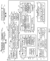
- FIG. 9 is a block diagram schematically representing an example manufacturing engine 500.
- the manufacturing engine 500 directs and manages additive manufacturing of a 3D object, including layering materials and/or dispensing fluid agents relative to a receiving surface to additively form a three-dimensional (3D) object.
- manufacturing engine 500 provides at least some example implementations of instructions 471 in memory 470 associated with control portion 460 ( FIG. 8A ).
- manufacturing engine 500 provides one example by which at least some examples previously described in association with at least FIGS. 1-8B may be implemented.
- manufacturing engine 500 comprises a material dispenser engine 510, fluid dispenser engine 520, color representation engine 540, material property engine 560, composition engine 580, energy function 590, and/or construction engine 600.
- the material dispenser engine 510 comprises a build material(s) function 512 to specify which build materials are used to form layers of a 3D object.
- a single build material may be used to form a 3D object.
- multiple different build materials may be used to form a 3D object.
- a single type of build material may be used to form a 3D object but different portions of the 3D object may be formed using variations of the single type of build material in which a first portion of the 3D object exhibits a first value of a non-color material property of the single type of build material and a second portion of the 3D object exhibits a different second value of the same non-color material property of the single type of build material.
- the material dispenser engine 510 enables the selection of materials to be deposited as a build material onto a receiving surface and/or previously formed layers of a partially formed 3D object.
- the material dispenser engine 510 comprises a material parameter 512. Via the material parameter 512, the manufacturing engine 500 specifies which material(s) and the quantity of such material which can be used to additively form a body of the 3D object. In some examples, these materials are deposited via material dispenser 50 of device 10 ( FIG. 1 ).
- the material controlled via material parameter 512 of material dispenser engine 510 may comprise polymers, ceramics, etc. having sufficient strength, formability, toughness, etc. for the intended use of the 3D object with at least some example materials being previously described in association with at least FIG. 1 .
- the fluid dispenser engine 520 may specify which fluid agents are to be selectively deposited onto a previously deposited layer of build material and/or in association with other agents. In some examples, such agents are deposited via fluid dispenser 58 ( FIG. 1 ). In some examples, the dispenser engine 520 comprises a first fluid agent engine 522 and a second fluid agent engine 530.
- the first fluid agent engine 522 controls dispensing via dispenser 58 of a first fluid agent (62 in FIG. 1 ) used as part of forming layers 82A ( FIGS. 1-7 ) of a build material in additively manufacturing a 3D object.
- the first fluid agent engine 522 and/or second fluid agent engine 530 may dispense fluid agents (via dispenser 58 in FIG. 1 ) according to a detailing parameter 526, a fusing parameter 528, and/or other parameter 529.
- the fusing parameter 528 controls dispensing of a fusing agent which may facilitate fusing of the layered first materials (e.g. a build material) into a monolithic structure, while the detailing parameter 526 controls dispensing of a detailing agent to complement fusing and/or otherwise modify an appearance of the layered build materials.
- other agents or additional agents are dispensed selectively as controlled via other parameter 528.
- the first fluid agent engine 522 comprises a colors parameter 524 to specify dispensing of colors via fluid dispenser 58 according to various color-related functions and parameters of the manufacturing engine 500 generally, and with particular respect to the color representation engine 540 ( FIG. 9 ).
- colors may comprise the assigned colors (applied to at least partially define an external surface) and which are intended to represent corresponding non-color material properties of interior portions of a 3D object.
- the second fluid agent engine 530 controls dispensing of a second fluid agent (e.g. 62 in FIG. 1 ), such as via a second fluid agent function 531 and/or a multiple fluid agent function 538.
- a second fluid agent e.g. 62 in FIG. 1
- the second fluid agent function 531 comprises a materials parameter 532 to control the type(s) and quantity of materials which may be incorporated with the dispensed second fluid agent, in some instances. These various materials exhibit different non-color material properties (e.g. electrical, mechanical, chemical, etc.) which may be infused into the various layers of the build material, as further described below.
- the materials parameter 532 may control a fraction (536) of solids (534) relative to the overall volume of second fluid agent dispensed. Accordingly, this control may indirectly determine a volume of ink flux (e.g. fluid components) in the overall volume of dispensed second fluid agent.
- fluid dispenser 58 ( FIG. 1 ) of device 20 may be configured with correspondingly separate reservoirs, delivery channels, etc. to enable such separate fluid agents and/or additives to be selectively dispensed as desired during the additive manufacturing of the 3D object.
- each different material may be contained in separate reservoir until deposited via material dispenser 50 ( FIG. 1 ).
- the color representation engine 540 at least partially controls and directs the manner in which various colors are assigned to represent various non-color material properties of various 3D objects (or portions thereof). In some examples, at least some examples of the present disclosure may be implemented via color representation engine 540.
- the color representation engine 540 comprises a color(s) function 541, color space function 542, an object function 543, a portion function 544, a value function 545, a discrete function 546, a continuous function 547, a gradient function 548, a half-toning function 550, a greyscale function 552, and a wavelength function 554, and/or a color map function 555, which includes a table parameter 556 and a rule parameter 557.
- the color map function 555 of color representation engine 540 implements a mapping of the colors (541) relative to objects (543) and/or portions (544) of 3D objects in association with non-color material properties (engine 560). In some examples, such mapping may be implemented in association with values 545 of non-color material properties per engine 560.
- the color map function 555 of color representation engine 540 implements such mapping according to a selectable color space (e.g. RGB, CYMK, etc.) per at least color space function 542.
- a selectable color space e.g. RGB, CYMK, etc.
- such color map(s) are at least partially implemented via a table per table parameter 556 and/or via a color mapping rule via rule parameter 557, as shown in FIG. 9 .
- At least some aspects of example implementations of the color map function 555 (and functions 541-552) were previously described in association with at least FIGS. 4B-4C and/or expressed in association with at least FIGS. 6A-7 .
- the color mapping may be implemented such that the one-to-one correspondence of the color-to-material property mapping can be expressed via any of a variety of rules provided that the color-to-material property relationship is monothonic.
- wavelength function 554 of color representation engine 540 at least some of the dispensed color (to represent a non-color material property) may be invisible to unaided human vision but otherwise visible via machine vision and/or with the assistance of ultraviolet (UV) light. In this way, the color information is retrievable when desired but is otherwise visually unobtrusive.
- UV ultraviolet
- the color representation engine 540 comprises a half-toning function 550 to cause the fluid dispenser 58 to dispense multiple different color agents via half-toning in at least selectable locations of an external surface 88 of a first portion (e.g. 71A in FIG. 1, 2 ) to simultaneously represent multiple, different non-color material properties or to simultaneously represent multiple, different values of a single non-color material property.
- a half-toning function 550 to cause the fluid dispenser 58 to dispense multiple different color agents via half-toning in at least selectable locations of an external surface 88 of a first portion (e.g. 71A in FIG. 1, 2 ) to simultaneously represent multiple, different non-color material properties or to simultaneously represent multiple, different values of a single non-color material property.
- the composition engine 580 of manufacturing engine 500 enables the selection of attributes by which the selected fluid agents are deposited via fluid dispenser engine 520.
- the composition engine 580 comprises a location parameter 581, a size parameter 582, a shape parameter 583, a quantity parameter 585, and a spacing parameter 586.
- the location parameter 581 can specify a location at which the various agents and/or a structural feature of the 3D object is located.
- the location parameter 581 can specify a location at which a color is to deposited at an external surface or at which a fusing agent is dispensed to cause fusing (e.g. via melting, via sintering, etc.) of a layer of material.
- the size parameter 582 can specify a size of the area over which the particular agent (e.g. color, detailing, etc.) is deposited.
- the size can be specified as an absolute quantity or as a relative quantity, i.e. a size relative to a size or volume of the surrounding material not receiving a particular agent.
- the shape parameter 583 enables specifying a shape over which a particular agent is deposited, which can be absolute or relative to the general shape of the 3D object.
- the quantity parameter 585 enables specifying a quantity of locations at which a particular agent is deposited on a layer of material.
- the spacing parameter 586 enables specifying a spacing between multiple locations at which a particular agent is deposited.
- manufacturing engine 500 may comprise a material property engine 560 to specify which material properties are already exhibited by a build material and/or to be exhibited by such build materials after dispensing fluid agents.
- At least some portions of at least some layers of the build material may already at least partially exhibit the material property (e.g. mechanical, electrical, chemical) specified for the selected/targeted locations without, or prior to, any operation or action by the fluid dispenser 58 and material property engine 560.
- various parameters of the materials property engine 560 track and/or reflect such already existing material properties of the 3D object.
- material property engine 560 comprises a mechanical parameter 561, electrical parameter 570, chemical parameter 577, multi-property parameter 578, and degree parameter 579.
- a material property of at least a portion of a 3D object may be at least partially specified and/or at least partially determined via an electrical property parameter 570.
- the material property may comprise electrically conductive properties (571), an electrically insulative properties (572), semi-conductive properties (574), and/or other electrical properties.
- electrically conductive properties 571
- electrically insulative properties 572
- semi-conductive properties 574
- Such material properties may be used to form various circuitry elements within and/or on the 3D object and/or may be used to form other non-circuitry features.
- any one of the properties (e.g. 561, 570, 577, 578, in FIG. 9 ) selectable via second fluid agent engine 530 also may be implemented via the first fluid agent in association with the other parameter 528 of first fluid engine 522 and/or also may be already incorporated with the build material deposited as one of the first layers (e.g. 82A) via the material dispenser 50 ( FIG. 1 ). Such implementation may complement the various properties (e.g. 561, 570, 577, 578 in FIG. 9 ) implemented via second fluid agent engine 530 ( FIG. 9 ) of dispenser 58 ( FIG. 1 ).
Applications Claiming Priority (1)
| Application Number | Priority Date | Filing Date | Title |
|---|---|---|---|
| PCT/US2017/029883 WO2018199960A1 (en) | 2017-04-27 | 2017-04-27 | Color representation of a property of a 3d object |
Publications (3)
| Publication Number | Publication Date |
|---|---|
| EP3551429A1 EP3551429A1 (en) | 2019-10-16 |
| EP3551429A4 EP3551429A4 (en) | 2020-08-05 |
| EP3551429B1 true EP3551429B1 (en) | 2022-07-27 |
Family
ID=63918635
Family Applications (1)
| Application Number | Title | Priority Date | Filing Date |
|---|---|---|---|
| EP17908061.9A Active EP3551429B1 (en) | 2017-04-27 | 2017-04-27 | Color representation of a property of a 3d object |
Country Status (4)
| Country | Link |
|---|---|
| US (1) | US11597154B2 (zh) |
| EP (1) | EP3551429B1 (zh) |
| CN (1) | CN110461576B (zh) |
| WO (1) | WO2018199960A1 (zh) |
Families Citing this family (2)
| Publication number | Priority date | Publication date | Assignee | Title |
|---|---|---|---|---|
| US11110648B2 (en) * | 2012-07-31 | 2021-09-07 | Makerbot Industries, Llc | Build material switching |
| WO2020214160A1 (en) * | 2019-04-17 | 2020-10-22 | Hewlett-Packard Development Company L.P. | Additive manufacturing process using colorant and laser fusion |
Family Cites Families (17)
| Publication number | Priority date | Publication date | Assignee | Title |
|---|---|---|---|---|
| US6612824B2 (en) | 1999-03-29 | 2003-09-02 | Minolta Co., Ltd. | Three-dimensional object molding apparatus |
| DE102006019963B4 (de) * | 2006-04-28 | 2023-12-07 | Envisiontec Gmbh | Vorrichtung und Verfahren zur Herstellung eines dreidimensionalen Objekts durch schichtweises Verfestigen eines unter Einwirkung von elektromagnetischer Strahlung verfestigbaren Materials mittels Maskenbelichtung |
| US20120065755A1 (en) | 2010-08-13 | 2012-03-15 | Sensable Technologies, Inc. | Fabrication of non-homogeneous articles via additive manufacturing using three-dimensional voxel-based models |
| US9999509B2 (en) | 2011-11-17 | 2018-06-19 | Stratasys Ltd. | System and method for fabricating a body part model using multi-material additive manufacturing |
| US20130287933A1 (en) * | 2012-04-25 | 2013-10-31 | Pierre J. Kaiser | Three-dimensional (3d) printing |
| EP2880638A1 (en) * | 2012-07-30 | 2015-06-10 | Materialise N.V. | Systems and methods for forming and utilizing bending maps for object design |
| EP2892708B1 (en) | 2012-09-05 | 2018-10-10 | Aprecia Pharmaceuticals LLC | Three-dimensional printing system and equipment assembly |
| FR2996160B1 (fr) * | 2012-09-28 | 2016-07-29 | Essilor Int | Procede de fabrication d'une lentille ophtalmique comportant une etape de marquage pour realiser des marques permanentes sur ladite lentille ophtalmique |
| US9643362B2 (en) * | 2013-03-15 | 2017-05-09 | Microsoft Technology Licensing, Llc | Full color three-dimensional object fabrication |
| US9305391B2 (en) | 2013-03-15 | 2016-04-05 | 3D Systems, Inc. | Apparatus and methods for detailing subdivision surfaces |
| EP3116961A1 (en) | 2014-03-11 | 2017-01-18 | 3D Systems, Incorporated | Inks for 3d printing |
| EP3132919B1 (en) * | 2014-04-14 | 2019-03-27 | Konica Minolta, Inc. | Three-dimensional fabricated object manufacturing apparatus and manufacturing method |
| CN106794633A (zh) | 2014-10-01 | 2017-05-31 | 惠普发展公司有限责任合伙企业 | 用于三维物体的生产的控制数据 |
| JP6524684B2 (ja) | 2015-02-09 | 2019-06-05 | セイコーエプソン株式会社 | 立体物造形装置、立体物造形方法、および立体物造形プログラム |
| US10678217B2 (en) | 2015-04-20 | 2020-06-09 | Hewlett-Packard Development Company, L.P. | Creating a voxel representation of a three dimensional (3-D) object |
| US20160311162A1 (en) * | 2015-04-24 | 2016-10-27 | Win-Hall Tech Sdn Bhd | Novel color 3d printer based on energy-curable color coating on transparent or translucent base material |
| KR102223993B1 (ko) | 2015-04-30 | 2021-03-05 | 휴렛-팩커드 디벨롭먼트 컴퍼니, 엘.피. | 다중-구조의 3d 물체의 프린팅 |
-
2017
- 2017-04-27 CN CN201780087469.5A patent/CN110461576B/zh active Active
- 2017-04-27 US US16/473,434 patent/US11597154B2/en active Active
- 2017-04-27 EP EP17908061.9A patent/EP3551429B1/en active Active
- 2017-04-27 WO PCT/US2017/029883 patent/WO2018199960A1/en unknown
Also Published As
| Publication number | Publication date |
|---|---|
| CN110461576B (zh) | 2023-02-03 |
| EP3551429A1 (en) | 2019-10-16 |
| EP3551429A4 (en) | 2020-08-05 |
| US20200147892A1 (en) | 2020-05-14 |
| WO2018199960A1 (en) | 2018-11-01 |
| US11597154B2 (en) | 2023-03-07 |
| CN110461576A (zh) | 2019-11-15 |
Similar Documents
| Publication | Publication Date | Title |
|---|---|---|
| JP6389554B2 (ja) | 印刷システムおよび印刷方法 | |
| CN105922748B (zh) | 一种用于产生三维(3d)打印零件的方法和系统 | |
| CN105916663A (zh) | 产生三维对象 | |
| US11260585B2 (en) | Indexing in 3D printing | |
| WO2016163391A1 (ja) | 三次元造形物の製造方法および製造装置 | |
| CN107211071B (zh) | 用于生成三维物体的装置、方法和可读介质 | |
| EP3551429B1 (en) | Color representation of a property of a 3d object | |
| JP2015221516A (ja) | 三次元構造物の形成装置および形成方法 | |
| TWI711531B (zh) | 立體列印裝置與其噴墨著色方法 | |
| JP6725361B2 (ja) | 立体物の造形方法および造形装置 | |
| CN109070462B (zh) | 在3d打印中形成微观结构 | |
| JP2017113986A (ja) | 立体物造形装置、立体物造形方法、及び、立体物造形装置の制御プログラム | |
| CN107211072B (zh) | 产生用于生产三维对象的控制数据的装置、方法和存储介质 | |
| CN110869192B (zh) | 用于制造三维物体的装置和方法以及三维打印机 | |
| US11724448B2 (en) | Disguising color in 3D object formation | |
| US20170190115A1 (en) | Direct dyeing type color fused deposition modeling three-dimensional printing apparatus and direct dyeing type color fused deposition modeling three-dimensional printing method | |
| US20230146931A1 (en) | Authentication surface feature in additive manufacturing | |
| WO2020141524A1 (en) | Method and system for improving color uniformity in inkjet printing | |
| JP2024514250A (ja) | 高スループット3次元印刷のためのシステム及び方法 | |
| JP2016221909A (ja) | 三次元造形方法 |
Legal Events
| Date | Code | Title | Description |
|---|---|---|---|
| STAA | Information on the status of an ep patent application or granted ep patent |
Free format text: STATUS: THE INTERNATIONAL PUBLICATION HAS BEEN MADE |
|
| PUAI | Public reference made under article 153(3) epc to a published international application that has entered the european phase |
Free format text: ORIGINAL CODE: 0009012 |
|
| STAA | Information on the status of an ep patent application or granted ep patent |
Free format text: STATUS: REQUEST FOR EXAMINATION WAS MADE |
|
| 17P | Request for examination filed |
Effective date: 20190708 |
|
| AK | Designated contracting states |
Kind code of ref document: A1 Designated state(s): AL AT BE BG CH CY CZ DE DK EE ES FI FR GB GR HR HU IE IS IT LI LT LU LV MC MK MT NL NO PL PT RO RS SE SI SK SM TR |
|
| AX | Request for extension of the european patent |
Extension state: BA ME |
|
| A4 | Supplementary search report drawn up and despatched |
Effective date: 20200703 |
|
| DAV | Request for validation of the european patent (deleted) | ||
| DAX | Request for extension of the european patent (deleted) | ||
| RIC1 | Information provided on ipc code assigned before grant |
Ipc: B29C 64/194 20170101AFI20200629BHEP Ipc: B29C 64/165 20170101ALN20200629BHEP Ipc: B29C 64/106 20170101ALI20200629BHEP Ipc: B33Y 40/00 20200101ALI20200629BHEP Ipc: B33Y 10/00 20150101ALI20200629BHEP Ipc: B29C 64/112 20170101ALI20200629BHEP Ipc: B29C 64/336 20170101ALI20200629BHEP |
|
| RIC1 | Information provided on ipc code assigned before grant |
Ipc: B29C 64/165 20170101ALN20220316BHEP Ipc: B33Y 10/00 20150101ALI20220316BHEP Ipc: B33Y 40/00 20150101ALI20220316BHEP Ipc: B29C 64/336 20170101ALI20220316BHEP Ipc: B29C 64/112 20170101ALI20220316BHEP Ipc: B29C 64/106 20170101ALI20220316BHEP Ipc: B29C 64/194 20170101AFI20220316BHEP |
|
| GRAP | Despatch of communication of intention to grant a patent |
Free format text: ORIGINAL CODE: EPIDOSNIGR1 |
|
| STAA | Information on the status of an ep patent application or granted ep patent |
Free format text: STATUS: GRANT OF PATENT IS INTENDED |
|
| RIC1 | Information provided on ipc code assigned before grant |
Ipc: B29C 64/165 20170101ALN20220328BHEP Ipc: B33Y 10/00 20150101ALI20220328BHEP Ipc: B33Y 40/00 20150101ALI20220328BHEP Ipc: B29C 64/336 20170101ALI20220328BHEP Ipc: B29C 64/112 20170101ALI20220328BHEP Ipc: B29C 64/106 20170101ALI20220328BHEP Ipc: B29C 64/194 20170101AFI20220328BHEP |
|
| INTG | Intention to grant announced |
Effective date: 20220425 |
|
| GRAS | Grant fee paid |
Free format text: ORIGINAL CODE: EPIDOSNIGR3 |
|
| GRAA | (expected) grant |
Free format text: ORIGINAL CODE: 0009210 |
|
| STAA | Information on the status of an ep patent application or granted ep patent |
Free format text: STATUS: THE PATENT HAS BEEN GRANTED |
|
| AK | Designated contracting states |
Kind code of ref document: B1 Designated state(s): AL AT BE BG CH CY CZ DE DK EE ES FI FR GB GR HR HU IE IS IT LI LT LU LV MC MK MT NL NO PL PT RO RS SE SI SK SM TR |
|
| REG | Reference to a national code |
Ref country code: CH Ref legal event code: EP |
|
| REG | Reference to a national code |
Ref country code: DE Ref legal event code: R096 Ref document number: 602017060049 Country of ref document: DE |
|
| REG | Reference to a national code |
Ref country code: AT Ref legal event code: REF Ref document number: 1506791 Country of ref document: AT Kind code of ref document: T Effective date: 20220815 |
|
| REG | Reference to a national code |
Ref country code: IE Ref legal event code: FG4D |
|
| REG | Reference to a national code |
Ref country code: LT Ref legal event code: MG9D |
|
| REG | Reference to a national code |
Ref country code: NL Ref legal event code: MP Effective date: 20220727 |
|
| PG25 | Lapsed in a contracting state [announced via postgrant information from national office to epo] |
Ref country code: SE Free format text: LAPSE BECAUSE OF FAILURE TO SUBMIT A TRANSLATION OF THE DESCRIPTION OR TO PAY THE FEE WITHIN THE PRESCRIBED TIME-LIMIT Effective date: 20220727 Ref country code: RS Free format text: LAPSE BECAUSE OF FAILURE TO SUBMIT A TRANSLATION OF THE DESCRIPTION OR TO PAY THE FEE WITHIN THE PRESCRIBED TIME-LIMIT Effective date: 20220727 Ref country code: PT Free format text: LAPSE BECAUSE OF FAILURE TO SUBMIT A TRANSLATION OF THE DESCRIPTION OR TO PAY THE FEE WITHIN THE PRESCRIBED TIME-LIMIT Effective date: 20221128 Ref country code: NO Free format text: LAPSE BECAUSE OF FAILURE TO SUBMIT A TRANSLATION OF THE DESCRIPTION OR TO PAY THE FEE WITHIN THE PRESCRIBED TIME-LIMIT Effective date: 20221027 Ref country code: NL Free format text: LAPSE BECAUSE OF FAILURE TO SUBMIT A TRANSLATION OF THE DESCRIPTION OR TO PAY THE FEE WITHIN THE PRESCRIBED TIME-LIMIT Effective date: 20220727 Ref country code: LV Free format text: LAPSE BECAUSE OF FAILURE TO SUBMIT A TRANSLATION OF THE DESCRIPTION OR TO PAY THE FEE WITHIN THE PRESCRIBED TIME-LIMIT Effective date: 20220727 Ref country code: LT Free format text: LAPSE BECAUSE OF FAILURE TO SUBMIT A TRANSLATION OF THE DESCRIPTION OR TO PAY THE FEE WITHIN THE PRESCRIBED TIME-LIMIT Effective date: 20220727 Ref country code: FI Free format text: LAPSE BECAUSE OF FAILURE TO SUBMIT A TRANSLATION OF THE DESCRIPTION OR TO PAY THE FEE WITHIN THE PRESCRIBED TIME-LIMIT Effective date: 20220727 Ref country code: ES Free format text: LAPSE BECAUSE OF FAILURE TO SUBMIT A TRANSLATION OF THE DESCRIPTION OR TO PAY THE FEE WITHIN THE PRESCRIBED TIME-LIMIT Effective date: 20220727 |
|
| REG | Reference to a national code |
Ref country code: AT Ref legal event code: MK05 Ref document number: 1506791 Country of ref document: AT Kind code of ref document: T Effective date: 20220727 |
|
| PG25 | Lapsed in a contracting state [announced via postgrant information from national office to epo] |
Ref country code: PL Free format text: LAPSE BECAUSE OF FAILURE TO SUBMIT A TRANSLATION OF THE DESCRIPTION OR TO PAY THE FEE WITHIN THE PRESCRIBED TIME-LIMIT Effective date: 20220727 Ref country code: IS Free format text: LAPSE BECAUSE OF FAILURE TO SUBMIT A TRANSLATION OF THE DESCRIPTION OR TO PAY THE FEE WITHIN THE PRESCRIBED TIME-LIMIT Effective date: 20221127 Ref country code: HR Free format text: LAPSE BECAUSE OF FAILURE TO SUBMIT A TRANSLATION OF THE DESCRIPTION OR TO PAY THE FEE WITHIN THE PRESCRIBED TIME-LIMIT Effective date: 20220727 Ref country code: GR Free format text: LAPSE BECAUSE OF FAILURE TO SUBMIT A TRANSLATION OF THE DESCRIPTION OR TO PAY THE FEE WITHIN THE PRESCRIBED TIME-LIMIT Effective date: 20221028 |
|
| PG25 | Lapsed in a contracting state [announced via postgrant information from national office to epo] |
Ref country code: SM Free format text: LAPSE BECAUSE OF FAILURE TO SUBMIT A TRANSLATION OF THE DESCRIPTION OR TO PAY THE FEE WITHIN THE PRESCRIBED TIME-LIMIT Effective date: 20220727 Ref country code: RO Free format text: LAPSE BECAUSE OF FAILURE TO SUBMIT A TRANSLATION OF THE DESCRIPTION OR TO PAY THE FEE WITHIN THE PRESCRIBED TIME-LIMIT Effective date: 20220727 Ref country code: DK Free format text: LAPSE BECAUSE OF FAILURE TO SUBMIT A TRANSLATION OF THE DESCRIPTION OR TO PAY THE FEE WITHIN THE PRESCRIBED TIME-LIMIT Effective date: 20220727 Ref country code: CZ Free format text: LAPSE BECAUSE OF FAILURE TO SUBMIT A TRANSLATION OF THE DESCRIPTION OR TO PAY THE FEE WITHIN THE PRESCRIBED TIME-LIMIT Effective date: 20220727 Ref country code: AT Free format text: LAPSE BECAUSE OF FAILURE TO SUBMIT A TRANSLATION OF THE DESCRIPTION OR TO PAY THE FEE WITHIN THE PRESCRIBED TIME-LIMIT Effective date: 20220727 |
|
| PGFP | Annual fee paid to national office [announced via postgrant information from national office to epo] |
Ref country code: FR Payment date: 20230321 Year of fee payment: 7 |
|
| REG | Reference to a national code |
Ref country code: DE Ref legal event code: R097 Ref document number: 602017060049 Country of ref document: DE |
|
| PG25 | Lapsed in a contracting state [announced via postgrant information from national office to epo] |
Ref country code: SK Free format text: LAPSE BECAUSE OF FAILURE TO SUBMIT A TRANSLATION OF THE DESCRIPTION OR TO PAY THE FEE WITHIN THE PRESCRIBED TIME-LIMIT Effective date: 20220727 Ref country code: EE Free format text: LAPSE BECAUSE OF FAILURE TO SUBMIT A TRANSLATION OF THE DESCRIPTION OR TO PAY THE FEE WITHIN THE PRESCRIBED TIME-LIMIT Effective date: 20220727 |
|
| PGFP | Annual fee paid to national office [announced via postgrant information from national office to epo] |
Ref country code: GB Payment date: 20230321 Year of fee payment: 7 |
|
| PLBE | No opposition filed within time limit |
Free format text: ORIGINAL CODE: 0009261 |
|
| STAA | Information on the status of an ep patent application or granted ep patent |
Free format text: STATUS: NO OPPOSITION FILED WITHIN TIME LIMIT |
|
| PG25 | Lapsed in a contracting state [announced via postgrant information from national office to epo] |
Ref country code: AL Free format text: LAPSE BECAUSE OF FAILURE TO SUBMIT A TRANSLATION OF THE DESCRIPTION OR TO PAY THE FEE WITHIN THE PRESCRIBED TIME-LIMIT Effective date: 20220727 |
|
| 26N | No opposition filed |
Effective date: 20230502 |
|
| PGFP | Annual fee paid to national office [announced via postgrant information from national office to epo] |
Ref country code: DE Payment date: 20230321 Year of fee payment: 7 |
|
| PG25 | Lapsed in a contracting state [announced via postgrant information from national office to epo] |
Ref country code: SI Free format text: LAPSE BECAUSE OF FAILURE TO SUBMIT A TRANSLATION OF THE DESCRIPTION OR TO PAY THE FEE WITHIN THE PRESCRIBED TIME-LIMIT Effective date: 20220727 |
|
| REG | Reference to a national code |
Ref country code: CH Ref legal event code: PL |
|
| PG25 | Lapsed in a contracting state [announced via postgrant information from national office to epo] |
Ref country code: LU Free format text: LAPSE BECAUSE OF NON-PAYMENT OF DUE FEES Effective date: 20230427 |
|
| REG | Reference to a national code |
Ref country code: BE Ref legal event code: MM Effective date: 20230430 |
|
| PG25 | Lapsed in a contracting state [announced via postgrant information from national office to epo] |
Ref country code: MC Free format text: LAPSE BECAUSE OF FAILURE TO SUBMIT A TRANSLATION OF THE DESCRIPTION OR TO PAY THE FEE WITHIN THE PRESCRIBED TIME-LIMIT Effective date: 20220727 |
|
| PG25 | Lapsed in a contracting state [announced via postgrant information from national office to epo] |
Ref country code: MC Free format text: LAPSE BECAUSE OF FAILURE TO SUBMIT A TRANSLATION OF THE DESCRIPTION OR TO PAY THE FEE WITHIN THE PRESCRIBED TIME-LIMIT Effective date: 20220727 Ref country code: LI Free format text: LAPSE BECAUSE OF NON-PAYMENT OF DUE FEES Effective date: 20230430 Ref country code: CH Free format text: LAPSE BECAUSE OF NON-PAYMENT OF DUE FEES Effective date: 20230430 |
|
| REG | Reference to a national code |
Ref country code: IE Ref legal event code: MM4A |
|
| PG25 | Lapsed in a contracting state [announced via postgrant information from national office to epo] |
Ref country code: BE Free format text: LAPSE BECAUSE OF NON-PAYMENT OF DUE FEES Effective date: 20230430 |
|
| PG25 | Lapsed in a contracting state [announced via postgrant information from national office to epo] |
Ref country code: IE Free format text: LAPSE BECAUSE OF NON-PAYMENT OF DUE FEES Effective date: 20230427 |
|
| PG25 | Lapsed in a contracting state [announced via postgrant information from national office to epo] |
Ref country code: IE Free format text: LAPSE BECAUSE OF NON-PAYMENT OF DUE FEES Effective date: 20230427 |