EP3551389B1 - Power tool and light unit - Google Patents
Power tool and light unit Download PDFInfo
- Publication number
- EP3551389B1 EP3551389B1 EP17878895.6A EP17878895A EP3551389B1 EP 3551389 B1 EP3551389 B1 EP 3551389B1 EP 17878895 A EP17878895 A EP 17878895A EP 3551389 B1 EP3551389 B1 EP 3551389B1
- Authority
- EP
- European Patent Office
- Prior art keywords
- light unit
- switch
- power tool
- housing
- light
- Prior art date
- Legal status (The legal status is an assumption and is not a legal conclusion. Google has not performed a legal analysis and makes no representation as to the accuracy of the status listed.)
- Active
Links
Images


Classifications
-
- B—PERFORMING OPERATIONS; TRANSPORTING
- B23—MACHINE TOOLS; METAL-WORKING NOT OTHERWISE PROVIDED FOR
- B23Q—DETAILS, COMPONENTS, OR ACCESSORIES FOR MACHINE TOOLS, e.g. ARRANGEMENTS FOR COPYING OR CONTROLLING; MACHINE TOOLS IN GENERAL CHARACTERISED BY THE CONSTRUCTION OF PARTICULAR DETAILS OR COMPONENTS; COMBINATIONS OR ASSOCIATIONS OF METAL-WORKING MACHINES, NOT DIRECTED TO A PARTICULAR RESULT
- B23Q17/00—Arrangements for observing, indicating or measuring on machine tools
- B23Q17/24—Arrangements for observing, indicating or measuring on machine tools using optics or electromagnetic waves
- B23Q17/2404—Arrangements for improving direct observation of the working space, e.g. using mirrors or lamps
-
- B—PERFORMING OPERATIONS; TRANSPORTING
- B23—MACHINE TOOLS; METAL-WORKING NOT OTHERWISE PROVIDED FOR
- B23Q—DETAILS, COMPONENTS, OR ACCESSORIES FOR MACHINE TOOLS, e.g. ARRANGEMENTS FOR COPYING OR CONTROLLING; MACHINE TOOLS IN GENERAL CHARACTERISED BY THE CONSTRUCTION OF PARTICULAR DETAILS OR COMPONENTS; COMBINATIONS OR ASSOCIATIONS OF METAL-WORKING MACHINES, NOT DIRECTED TO A PARTICULAR RESULT
- B23Q17/00—Arrangements for observing, indicating or measuring on machine tools
-
- B—PERFORMING OPERATIONS; TRANSPORTING
- B25—HAND TOOLS; PORTABLE POWER-DRIVEN TOOLS; MANIPULATORS
- B25B—TOOLS OR BENCH DEVICES NOT OTHERWISE PROVIDED FOR, FOR FASTENING, CONNECTING, DISENGAGING OR HOLDING
- B25B23/00—Details of, or accessories for, spanners, wrenches, screwdrivers
- B25B23/18—Devices for illuminating the head of the screw or the nut
-
- B—PERFORMING OPERATIONS; TRANSPORTING
- B25—HAND TOOLS; PORTABLE POWER-DRIVEN TOOLS; MANIPULATORS
- B25F—COMBINATION OR MULTI-PURPOSE TOOLS NOT OTHERWISE PROVIDED FOR; DETAILS OR COMPONENTS OF PORTABLE POWER-DRIVEN TOOLS NOT PARTICULARLY RELATED TO THE OPERATIONS PERFORMED AND NOT OTHERWISE PROVIDED FOR
- B25F5/00—Details or components of portable power-driven tools not particularly related to the operations performed and not otherwise provided for
- B25F5/02—Construction of casings, bodies or handles
- B25F5/021—Construction of casings, bodies or handles with guiding devices
-
- F—MECHANICAL ENGINEERING; LIGHTING; HEATING; WEAPONS; BLASTING
- F21—LIGHTING
- F21S—NON-PORTABLE LIGHTING DEVICES; SYSTEMS THEREOF; VEHICLE LIGHTING DEVICES SPECIALLY ADAPTED FOR VEHICLE EXTERIORS
- F21S9/00—Lighting devices with a built-in power supply; Systems employing lighting devices with a built-in power supply
- F21S9/02—Lighting devices with a built-in power supply; Systems employing lighting devices with a built-in power supply the power supply being a battery or accumulator
-
- F—MECHANICAL ENGINEERING; LIGHTING; HEATING; WEAPONS; BLASTING
- F21—LIGHTING
- F21V—FUNCTIONAL FEATURES OR DETAILS OF LIGHTING DEVICES OR SYSTEMS THEREOF; STRUCTURAL COMBINATIONS OF LIGHTING DEVICES WITH OTHER ARTICLES, NOT OTHERWISE PROVIDED FOR
- F21V21/00—Supporting, suspending, or attaching arrangements for lighting devices; Hand grips
-
- F—MECHANICAL ENGINEERING; LIGHTING; HEATING; WEAPONS; BLASTING
- F21—LIGHTING
- F21V—FUNCTIONAL FEATURES OR DETAILS OF LIGHTING DEVICES OR SYSTEMS THEREOF; STRUCTURAL COMBINATIONS OF LIGHTING DEVICES WITH OTHER ARTICLES, NOT OTHERWISE PROVIDED FOR
- F21V23/00—Arrangement of electric circuit elements in or on lighting devices
- F21V23/04—Arrangement of electric circuit elements in or on lighting devices the elements being switches
- F21V23/0442—Arrangement of electric circuit elements in or on lighting devices the elements being switches activated by means of a sensor, e.g. motion or photodetectors
- F21V23/0471—Arrangement of electric circuit elements in or on lighting devices the elements being switches activated by means of a sensor, e.g. motion or photodetectors the sensor detecting the proximity, the presence or the movement of an object or a person
-
- F—MECHANICAL ENGINEERING; LIGHTING; HEATING; WEAPONS; BLASTING
- F21—LIGHTING
- F21V—FUNCTIONAL FEATURES OR DETAILS OF LIGHTING DEVICES OR SYSTEMS THEREOF; STRUCTURAL COMBINATIONS OF LIGHTING DEVICES WITH OTHER ARTICLES, NOT OTHERWISE PROVIDED FOR
- F21V33/00—Structural combinations of lighting devices with other articles, not otherwise provided for
- F21V33/008—Leisure, hobby or sport articles, e.g. toys, games or first-aid kits; Hand tools; Toolboxes
Definitions
- This application relates to a power tool and a light unit, e.g., a pneumatic power tool with a removable light unit.
- Power tools may be used in areas where operation would be enhanced by additional lighting.
- Some power tools have integral light units for providing illumination.
- the integral light units may be powered by the same electrical power supply (e.g., a battery or an AC power supply) that powers the power tool. Operation of the light unit may be controlled by a switch that controls electrical power delivery to the power tool and/or by a separate switch.
- Pneumatic power tools are also used in many applications where additional lighting is desirable. Pneumatic power tools generally do not include an electrical power supply needed to power a light unit.
- EP Patent Application No. 1281486 A1 discloses and adaptor for use with an electric power tool.
- the disclosed adaptor includes a main body that has a light assembly and coupling portion having a configuration identical to a coupling portion of a battery pack that is attached to the electric power tool.
- US Patent Application No. 2011/00583356 A1 discloses a power tool with a light emitting assembly.
- the disclosed light emitting assembly is fixed to the power tool and includes wires to power the light.
- EP 2551062 A1 discloses a lighted power tool.
- Said tool includes a first coil affixed to the body of the power tool, and a second coil coupled to and configured to rotate with the output member.
- EP 1125698 A1 discloses a handheld power tool.
- US Patent Application 2016/0069548 A1 discloses a ring light for rotary spindle based machines. This document discloses the preamble of claim 1.
- a light unit for a tool comprises the features of claim 1.
- the light unit housing may be removably coupled to the tool housing by a bayonet connection so that the light unit housing is rotatable between an unlocked position and a locked position.
- the light unit housing further may include a locking mechanism configured to maintain the light unit housing in the locked position.
- the locking mechanism may include at least one of a leaf spring, a locking tab, and a button configured to be received in a recess.
- the light may include one or more LEDs.
- the sensor may include a Hall sensor configured to sense movement of a magnet coupled to the switch of a tool, a toggle switch or a pressure switch configured to sense movement of the switch of the tool.
- the controller may include a timer configured to keep the light ON for a predetermined time period after the switch has been actuated or deactivated.
- a USB port or one or more electrical contacts may be configured to provide power for recharging the battery.
- a power tool comprises the features of claim 9.
- the light unit housing may be removably coupled to the tool housing by a bayonet connection.
- the light unit housing further may include a locking mechanism configured to maintain the light unit housing in a locked position on the tool housing.
- the locking mechanism may include at least one of a leaf spring, a locking tab, and a button configured to be received in a recess.
- the light may include one or more LEDs.
- the sensor may include a Hall sensor and the sensor target may include a magnet. Alternatively, the sensor may include a toggle switch or a pressure switch and the sensor target comprises a portion of the switch on the tool that engages the toggle switch or the pressure switch.
- the controller may include a timer configured to keep the light ON for a predetermined time period after the switch has been actuated or deactivated.
- a USB port or one or more electrical contacts may be configured to provide power for recharging the battery.
- the light unit may be removable from a power tool.
- the light unit may have its own rechargeable battery so that it is usable with a pneumatic power tool.
- the light unit may turn on the light ON automatically when sensing when the tool is actuated by a user.
- FIGS. 1A and 1B illustrate an embodiment of a power tool 10 and a removable light unit 30.
- the power tool 10 is a pneumatic tool (in this case a pneumatic impact wrench) that is operable by compressed fluid, such as air.
- the power tool can comprise any one of numerous other types of power tools such as other pneumatic power tools (e.g., pneumatic drills, impact drivers, grinders, saws, hammers, etc.) or electric (e.g., battery or AC powered) power tools (e.g., drills, impact drivers, impact wrenches, impact drivers, saws, hammers, etc.).
- the power tool 10 includes a power tool housing 12 that includes a rear portion 14 containing a motor (not shown; in this case a pneumatic motor), a front portion 16 containing a transmission and/or impact mechanism (not shown), and a smaller diameter nose portion 17 extending forward from the front portion 16.
- An output member 19 (in this case a square drive shaft) is driven by the motor and the transmission and/or impact mechanism and extends outward from the nose portion 17 of the power tool housing 12 along an axis X.
- a handle 18 extends downward from the power tool housing 12 and includes a switch or trigger 20 configured to be depressed by a user to control delivery of fluid to the motor (or electric power in the case of an electric tool) to control operation of the tool 10.
- an air inlet 22 configured to receive input of compressed fluid, e.g., from a compressor.
- the light unit 30 includes a light unit housing 32 having an annular portion 34 with a central opening 36 that is concentric with the axis X.
- the light unit housing 32 also includes a flange portion 38 extending rearward from the annular portion 34 toward the tool housing, parallel to and offset from the axis X.
- the light unit housing 32 is removably coupleable to the tool housing 12 with the annular portion 34 receivable over the nose portion 17 and the flange portion 38 disposed below the front portion 16 and adjacent the switch 20, between the front portion 16 and the switch 20.
- the light unit housing 32 may be lockably coupled to the tool housing 12, e.g., according to one or more of the embodiments described below.
- an annular or partially annular printed circuit board (PCB) 40 is received in a groove 41 in the annular portion 34 of the light unit housing 32.
- a light 42 e.g., one or more LEDs.
- the LEDs are covered by a lens or transparent or translucent cover 44 to protect the light 42 from dust and debris.
- a controller 46 e.g., a processor, a microprocessor, and/or a digital or analog control circuit
- the PCB 40 may also include other electrical circuit components (e.g., a DC power supply, various resistors, capacitors, diodes, and transistors, etc.) for controlling the light 42 and other light unit components, as will be well known to one of ordinary skill in the art.
- the PCB 40 may be heat staked to the light unit housing 32 by heat meltable protrusions 48.
- the PCB may be attached to the light unit housing by one or more screws, snaps, or rivets.
- the battery 50 Received in a front pocket 49 in the flange portion 38 is a battery 50 that is configured to provide electrical power to the light 42.
- the battery 50 is a rechargeable lithium ion pouch battery.
- the battery 50 may be any type of rechargeable or non-rechargeable battery, such as a lithium-ion cylindrical cell, a nickel-cadmium battery, a coin cell, or an alkaline battery.
- a charging port 52 e.g., a USB or micro-USB port
- the PCB may include a charging circuit (not shown) configured to control the charging and discharging of the battery 50.
- a sensor 56 is received in a rear pocket 54 of the flange portion 38 for sensing movement of the switch or trigger 20.
- the sensor 56 comprises a Hall sensor 58 mounted to a Hall board 60.
- the switch 20 includes a sensor target 62, e.g., a permanent magnet.
- the sensor 56 is configured to sense the position of the sensor target 62 as the switch or trigger 20 is moved between a fully actuated position and a fully deactivated position.
- the sensor 56 may generate an output electrical signal to the controller 46 corresponding to a strength of a magnetic field generated by the sensor target 62. The strength of this magnetic field may correlate with a positon of the sensor target 62 (and thus of the switch or trigger 20) relative to the sensor 56.
- the magnet moves from position 1 to position 2 and then to position 3.
- the light is OFF and the tool is OFF (i.e., the valve that controls fluid delivery to the motor is closed).
- the switch or trigger 20 is actuated a small distance to position 2, the valve is either not yet open, so the tool remains OFF, or is only open by a small amount, while the Hall sensor 58 senses a change in the magnetic field and transmits a signal to the controller 46 indicating that the switch or trigger 20 has been actuated, and the controller 46 causes the light 42 to turn ON.
- the controller may have or be programmed with a timer that causes the light to remain ON for a predetermined period of time after the switch 20 has been actuated or deactivated. Examples of such timer features can be found in, e.g., U.S. Patent Nos. 6,511,200 and 9,225,275 .
- FIG. 5 illustrates another embodiment of a power tool 110, similar to the power tool 10, and a light unit 130, which may be integral with or removable from the power tool 110. This embodiment is not according to the claimed invention.
- the power tool 110 has a tool housing 112, a handle 118, and a switch or trigger 120 for actuating the tool.
- the light unit 130 includes a light unit housing 132 coupled to the top of the tool housing 112.
- the light unit housing 132 contains a light 142 (e.g., one or more LEDs) covered by a lens or transparent or translucent cover 144 to protect the light 142 from dust and debris.
- the light unit housing 132 also contains a controller 146 (e.g., a processor, a microprocessor, and/or a control circuit) that controls power delivery to and illumination of the light 142 and other electrical circuit components (e.g., a DC power supply, various resistors, capacitors, diodes, and transistors, etc.) for controlling the light 142 and other light unit components, as will be well known to one of ordinary skill in the art.
- a controller 146 e.g., a processor, a microprocessor, and/or a control circuit
- other electrical circuit components e.g., a DC power supply, various resistors, capacitors, diodes, and transistors, etc.
- Received in the light unit housing 142 is a battery 150 that is configured to provide electrical power to the light 142.
- the battery 150 is a rechargeable lithium ion battery.
- the battery 150 may be any type of rechargeable or non-rechargeable battery, such as a lithium-ion cylindrical cell, a nickel-cadmium battery, a coin cell, or an alkaline battery.
- a sensor 156 Received in the tool housing 112 and electrically in communication with the controller 146 is a sensor 156, e.g., a Hall sensor.
- the switch or trigger 120 includes a sensor target 162, e.g., a permanent magnet, the position of which is sensed by the sensor 156.
- the sensor 156 senses movement of the sensor target 162, and thus of the switch or trigger 120, and communicates with the controller 146 to cause the light 142 to turn ON or OFF based on movement of the switch or trigger 120 and the sensor target 162 relative to the sensor 156, e.g., in the manner described above with respect to FIG. 4 .
- FIG. 6 illustrates another embodiment of a power tool 210, similar to the power tools 10, 110, and a light unit 230, similar to light unit 130, which may be integral with or removable from the power tool 210.
- the power tool 210 has a tool housing 212, a handle 218, and a switch 220 for actuating the tool.
- the light unit 230 includes a light unit housing 232 coupled to the top of the tool housing 212.
- the light unit housing 232 contains a light 242 (e.g., one or more LEDs) covered by a lens or transparent or translucent cover 244 to protect the light 242 from dust and debris.
- a light 242 e.g., one or more LEDs
- the light unit housing 232 also contains a controller 246 (e.g., a processor, a microprocessor, and/or a control circuit) that controls power delivery to and illumination of the light 242 and other electrical circuit components (e.g., a DC power supply, various resistors, capacitors, diodes, and transistors, etc.) for controlling the light 242 and other light unit components, as will be well known to one of ordinary skill in the art.
- a controller 246 e.g., a processor, a microprocessor, and/or a control circuit
- other electrical circuit components e.g., a DC power supply, various resistors, capacitors, diodes, and transistors, etc.
- Received in the light unit housing 232 is a battery 250 that is configured to provide electrical power to the light 242.
- the battery 250 is a rechargeable lithium ion battery.
- the battery 250 may be any type of rechargeable or non-rechargeable battery, such as a lithium-ion cylindrical cell, a nickel-cadmium battery, a coin cell, or an alkaline battery.
- a sensor 256 Received in the tool housing 212 and electrically in communication with the controller 246 is a sensor 256, e.g., a Hall sensor.
- the switch 220 includes a sensor target 262, e.g., a permanent magnet, the position of which is sensed by the sensor 256.
- the sensor 256 and sensor target 262 differ from sensor 256 and sensor target 262 insofar as the sensor 256 is positioned behind the switch or trigger 210 and the sensor target 262 faces toward the sensor 256.
- the sensor 256 senses movement of the sensor target 262, and thus of the switch or trigger 220, and communicates with a controller to cause the light 242 to turn ON or OFF based on movement of the switch or trigger 220 and the sensor target 262 relative to the sensor 256, e.g., in the manner described above with respect to FIG. 4 .
- the light units 30, 130, 230 may additionally or alternatively be provided with a motion sensing circuit 300 for controlling operation of the lights 42, 142, 242.
- the motion sensing circuit 300 may include a motion sensor 302, e.g., a gyroscope and/or an accelerometer, which senses motion or vibration of the power tool 10, 110, 210.
- the motion sensor 302 may be powered by the battery 50, 150, 250 and provide a signal output to the controller 46, 146, 246 that corresponds to motion sensed by the motion sensor 302.
- the controller 46, 146, 246 can control power deliver to and illumination of the light 42, 142, 242.
- the controller 46, 146, 246 can causes the light 42, 142, 242 to turn ON until the motion has subsided, or until a predetermined time period has elapsed.
- this motion sensing circuit 300 for controlling illumination of the light unit could either supplement or replace the control of the light unit based on movement of the switch 20, 120, 220, as described above.
- a power tool 410 and a light unit 430 (similar to the power tools 10, 110, 210 and light units 30, 130, 230) provide an alternative way of charging a battery 450 in the light unit 430.
- the power tool 410 includes a power tool housing 412 that includes a rear portion 414 containing a motor, a front portion 416 containing a transmission and/or impact mechanism, and a handle 418 extending downward from the rear portion 414.
- Positioned at a front end 415 of the rear portion 414 of the tool housing 412 are charging terminals 453, which are electrically connected to a charging circuit 451 for charging the battery 450.
- a charger 455 includes a cradle 459, one or more charging terminals 457 and a plug 461 configured to electrically connect the charger 455 to a source of electrical power, e.g., AC mains.
- the power tool 410 is receivable in the charger 455 with the front portion 416 of the tool housing 412 received in the cradle 459 at an angle, such that the charging terminals 453 of the power tool 410 mate with the charging terminals 457 of the charger 455. This provides a convenient way to recharge the battery 450 while storing the power tool 410.
- a power tool 510 and a light unit 530 (similar to the power tools 10, 110, 210, 410 and light units 30, 130, 230, 430) provides an alternative way of charging a battery 550 in the light unit 530.
- the power tool 510 includes a power tool housing 512 that includes a rear portion 514 containing a motor, a front portion 516 containing a transmission and/or impact mechanism, and a handle 518 extending downward from the rear portion 514.
- the handle 518 includes a charging port 552 (e.g., a USB or micro-USB port) that is electrically connected to a charging circuit 551 in the light unit 550 for charging the battery 550.
- a charging port 552 e.g., a USB or micro-USB port
- the charging port 552 When not in use, the charging port 552 is covered by a door 553 to protect the charging port 552 from dust and debris.
- the battery 530 can be charged by connecting a charging terminal, cable or wire (e.g., a USB or micro-USB cable 555) to the charging port 552, which enables the charging circuit 551 to control charging of the battery 550.
- a power tool 610 and a light unit 630 (similar to the power tools 10, 110, 210, 410, 510 and light units 30, 130, 230, 430, 530) provides an alternative way of charging a battery 650 in the light unit 630.
- the power tool 610 includes a power tool housing 612 that includes a rear portion 614 containing a motor (not shown; in this case a pneumatic motor), a front portion 616 containing a transmission and/or impact mechanism (not shown), and a handle 618 extending downward from the rear portion 614.
- the handle includes an air inlet 622 and an air outlet 623.
- a charger 655 includes a cradle 659 configured to receive the base 625 of the handle 618.
- the charger 655 has one or more charging terminals 657 and a plug 661 configured to electrically connect the charger 655 to a source of electrical power, e.g., AC mains.
- the handle 618 of the power tool 610 is receivable in the cradle 659 with the charging terminals 652 of the power tool 610 mating with the charging terminals 657 of the charger 655. This provides a convenient way to recharge the battery 650 while storing the power tool 610.
- a power tool 710 and a light unit 730 (similar to the power tools 10, 110, 210, 410, 510, 610 and light units 30, 130, 230, 430, 530, 630) provides an alternative way of charging a battery 750 in the light unit 730.
- the power tool 710 includes a power tool housing 712 that includes a rear portion 714 containing a motor (not shown; in this case a pneumatic motor), a front portion 716 containing a transmission and/or impact mechanism (not shown), and a handle 718 extending downward from the rear portion 714.
- annular conductive band 752 Positioned at a front end 715 of the rear portion 714 of the tool housing 712 is an annular conductive band 752, which is electrically connected to one pole (e.g., positive) of the charging circuit 751 for charging the battery 750.
- the other pole (e.g., negative) of the charging circuit 751 is electrically connected to an air inlet 722, which is composed of a conductive material.
- a charger 755 includes a cradle 759, a first annular charging terminal 757 configured to mate with the conductive band 752, a second pad-shaped charging terminal 758 configured to mate with the air inlet 722, and a plug 761 configured to electrically connect the charger 755 to a source of electrical power, e.g., AC mains.
- the power tool 710 is receivable in the cradle 759 of the charger 755, such that the conductive band 752 mates with the annular charging terminal 757 and the air inlet 722 mates with the charging pad 758. This provides a convenient way to recharge the battery 750 while storing the power tool 710.
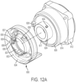
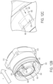
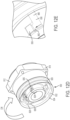
- FIGS. 12A-12E illustrate an embodiment of a locking mechanism for removably and securely coupling a housing 832 of a light unit 830 (similar to housing 32 of light unit 30) to a front portion 814 and nosepiece 817 of a power tool housing 812 (similar to a front portion 16 and nosepiece 17 of power tool housing 12) using a bayonet-style attachment.
- the nosepiece 817 includes a radial projection 824, an annular outer rib support 826, and a locking recess 828.
- the light unit housing 832 includes an annular wall portion 834, a central opening 835 defining an interior L-shaped slot 836, and a V-shaped leaf spring 838 having two legs 837 joined at a curved vertex 839.
- the annular wall portion 834 of the light unit housing 832 is received in an axial direction A over the outer rib support 826 with the radial projection 824 received in an axial portion 840 of the L-shaped slot 836.
- the light unit housing 832 is rotated in a clockwise direction CW relative to the power tool housing 812.
- the light unit housing 832 is rotatable in a counterclockwise direction CCW to an unlocked position where the leaf spring 838 is disengaged from the locking recess 840 and the radial projection 824 is aligned with the axial portion 840 of the L-shaped slot 836 to facilitate removing the light unit housing 832 from the power tool housing 812.
- FIGS. 13A-13G illustrate another embodiment of a locking mechanism for removably and securely coupling a housing 932 of a light unit 930 (similar to housing 32 of light unit 30) to a front portion 914 and nosepiece 917 of a power tool housing 912 (similar to a front portion 16 and nosepiece 17 of power tool housing 12) using a bayonet-style attachment.
- the nosepiece 917 includes a plurality of radial projections 924, an annular outer support rib 926, and a locking recess 928 defined in the support rib 926.
- the light unit housing 932 includes an annular wall portion 934 carrying a light 942 with a transparent cover 944.
- the annular wall portion 934 has an inner annular wall 940 that defines a central opening 935.
- a plurality of L-shaped slots 936 are also defined in the inner annular wall 940.
- Each L-shaped slot 936 includes an axial portion 937 and a circumferential portion 939.
- the annular wall portion 934 also has an outer annular wall 941 carries a locking button 946 that is biased radially outwardly by a compression spring 948.
- the locking button 946 includes a wide base portion 954, a narrow top portion 956, and a recessed portion 950 with a ramped surface 952 connecting the base portion 954 to the top portion 956.
- FIGS. 13C-13G illustrate installation and locking of the light unit 930 on the power tool housing 912.
- the light unit housing 932 is rotationally positioned relative to the power tool housing 912 so that the radial projections 924 on the nosepiece 917 are aligned with the axial portions 937 of the L-shaped slots 936 on the inner annular wall 940 of the light unit housing 932.
- the light unit housing 932 is moved in a direction A axially toward the power tool housing 912, so that the radial projections 924 are received in the axial portions 937 of the L-shaped slots 936 and the outer annular wall 941 is received around the support rib 926.
- the support rib 926 engages the ramped surface 952 in the locking button 946, which pushes the locking button in a radially inward direction RI against the force of the spring 948.
- the user then rotates the light unit housing 932 in a clockwise direction CW so that the radial projections 924 are received in the circumferential portions 939 of the L-shaped slots 936.
- the recessed portion 950 of the locking button 946 is aligned with the locking recess 928 in the support rib 926, removing the force that the support rib 926 exerts on the ramped surface 952 of the locking button 946.
- the biasing force of the spring 948 causes the locking button 946 to move in a radially outward direction RO so that the base portion 954 of the locking button 946 is caught in the locking recess 928 of the support rib 926, locking the light unit housing 932 on the power tool housing 912.
- the user depresses the locking button 946 in the radial inward direction RI against the force of the spring 948 and rotates the light unit housing 932 in a counterclockwise direction until the radial projections 924 are aligned with the axial portions 937 of the L-shaped slots 936.
- the user can then pull the light unit housing 932 axially away from the power tool housing 912 to remove the light unit housing 932 from the power tool housing 912.
- FIGS. 14A-14I illustrate another embodiment of a locking mechanism for removably and securely coupling a housing 1032 of a light unit 1030 (similar to housing 32 of light unit 30) to a front portion 1014 and nosepiece 1017 of a power tool housing 1012 (similar to a front portion 16 and nosepiece 17 of power tool housing 12) using a bayonet-style attachment.
- the nosepiece 1017 includes a plurality of radial projections 1024, an annular outer rib support 1026, and a plurality of locking features 1028 on the rib support 1026. As shown in FIG.
- each locking feature 1028 includes an elongated circumferential receiving recess 1040, a shorter circumferential locking recess 1042 and a tapered protrusion 1044 between the receiving recess 1040 and the locking recess 1042.
- the light unit housing 1032 includes an annular wall portion 1034 with a central opening 1035 defining a plurality of interior L-shaped slots 1036 defined in the central opening 1035 of the annular wall portion 1034.
- the interior of the annular wall portion 1034 also defines a plurality of resilient locking tabs 1038. As shown in FIGS.
- the annular wall portion 1034 of the light unit housing 1032 is received in an axial direction over the outer rib support 1026 with the radial projections 1024 received in axial portions 1037 of the L-shaped slots 1036 and with locking tabs 1038 received in the receiving recesses 1040.
- the light unit housing 1032 is rotated in a clockwise direction CW relative to the power tool housing 1012.
- the light unit housing 1032 is rotatable back to the unlocked position by rotating it in a counterclockwise direction CCW so that the locking tabs 1038 ride over the tapered protrusions 1044, causing the annular wall portion 1034 to deflect until the locking tabs 1038 are received in the receiving recesses 1040 and the radial projection 1024 is aligned with the axial portion 1037 of the L-shaped slot 1036.
- the light unit housing 1032 can be pulled axially off of the power tool housing 1012 to remove the light unit housing 1032 from the power tool housing 1012.
- FIGS. 15A-15G illustrate another embodiment of a power tool 1110 (e.g., a pneumatic or electric power tool) and a removable light unit 1130, similar to the previously described embodiments of power tools and light units.
- the power tool 1110 and light unit 1130 differs from the previously described embodiments in the design of a sensor and sensor target for causing the light unit 1130 to turn ON when the switch or trigger of the power tool 1110 is actuated.
- the power tool 1110 includes a power tool housing 1112 that includes a rear portion 1114 containing a motor (not shown), a front portion 1116 containing a transmission and/or impact mechanism (not shown), and a smaller diameter nose portion 1117 extending forward from the front portion 1116.
- An output member 1119 (in this case a square drive shaft) is driven by the motor and the transmission and/or impact mechanism and extends outward from the nose portion 1117 of the power tool housing 1112 along an axis X.
- a handle 1118 extends downward from the power tool housing 1112 and includes a switch or trigger 1120 configured to be depressed by a user to control the motor.
- the light unit 1130 includes a light unit housing 1132 having an annular portion 1134 with a central opening 1136 concentric with the axis X, and a flange portion 1138 extending rearward from the annular portion 1134 toward the tool housing 1112, parallel to and offset from the axis X.
- Received in the flange portion 1138 are a battery 1161 and a controller 1146 (e.g., a control circuit, a microprocessor, or a microcontroller).
- a controller 1146 e.g., a control circuit, a microprocessor, or a microcontroller.
- Received in the annular portion 1134 is a light 1142 that is electrically connected to the battery 1161 and the controller 1146.
- the light unit housing 1132 is removably coupleable to the tool housing 1112 with the annular portion 1134 receivable over the nose portion 1117 and the flange portion 1138 disposed below the front portion 1116 and adjacent the switch 1120, between the front portion 1116 and the switch or trigger 1120.
- the light unit housing 1132 may be lockably coupled to the tool housing 1112, e.g., according to one or more of the embodiments described above.
- a sensor in the form of a toggle or pressure switch 1156 is located in the flange portion 1138 and is coupled to the controller 1146.
- the toggle or pressure switch 1156 is configured to sense movement of the switch or trigger 1120 of the power tool 1110.
- the switch or trigger 1120 includes a sensor target in the form of a recess 1162 that receives an arm 1157 of the toggle or pressure switch 1156.
- the recess 1162 is open to one side of the switch or trigger 1120 to facilitate receiving the arm 1157 in the recess 1162 when the light unit housing 1132 is installed on the power tool housing 1112 using one of the bayonet-type connections described above. As shown in FIGS.
- the toggle or pressure switch 1156 is configured to sense the position of the switch or trigger 1120 by moving axially toward the tool housing 1112 as the switch or trigger 1120 is moved from a fully deactivated position to a partially or fully activated position. Depressing the switch or trigger 1120 causes the arm 1157 to pivot toward the power tool housing 1112, which causes the toggle or pressure switch 1156 to close. In one embodiment, when the switch or trigger 1120 is actuated a small distance, the power tool motor remains OFF or rotates at a very low speed, while the toggle or pressure switch 1156 closes, and the controller 1146 causes the light 1142 to turn ON.
- the toggle or pressure switch 1156 When the switch or trigger 1120 is actuated a larger distance, the toggle or pressure switch 1156 remains closed so that the light 1142 remains ON, while the motor is activated to run at a faster or full speed. The motor and the light remain ON until the switch or trigger 1120 is deactivated or released.
- the controller 1146 may have or be programmed with a timer that causes the light to remain ON for a predetermined period of time after the switch 1120 has been actuated or deactivated. Examples of such timer features can be found in, e.g., U.S. Patent Nos. 6,511,200 and 9,225,275 .
- FIGS. 16A-16B illustrate another embodiment of a power tool 1210 (e.g., a pneumatic or electric power tool) and a removable light unit 1230, similar to the previously described embodiments of power tools and light units.
- the power tool 1210 and light unit 1230 differ from the previously described embodiments in the design of a sensor and sensor target for causing the light unit 1230 to turn ON when the switch or trigger of the power tool 1210 is actuated.
- the power tool 1210 includes a power tool housing 1212 that includes a rear portion 1214 containing a motor (not shown), a front portion 1216 containing a transmission and/or impact mechanism (not shown), and a smaller diameter nose portion (not shown) extending forward from the front portion 1216.
- An output member (not shown, e.g., a square drive shaft) is driven by the motor and the transmission and/or impact mechanism and extends outward from the nose portion of the power tool housing 1212 along an axis X.
- a handle 1218 extends downward from the power tool housing 1212 and includes an inlet passageway 1219 for delivering compressed air to the motor.
- a switch or trigger 1220 is coupled to the handle 1218 and is linked to a valve 1221 in the inlet passageway 1219. As shown in FIG. 16B , the switch or trigger 1220 can be actuated or depressed, which opens the valve 1221 to deliver air to the motor.
- the light unit 1230 includes a light unit housing 1232 having an annular portion 1234 concentric with the axis X, and a flange portion 1238 extending rearward from the annular portion 1234 toward the tool housing 1212, parallel to and offset from the axis X.
- Received in the flange portion 1238 are a battery 1261, a controller 1246 (e.g., a control circuit, a microprocessor, or a microcontroller), and a make or break electrical switch 1247.
- Received in the annular portion 1234 is a light 1242 that is electrically connected to the battery 1261 and the controller 1246 via the make or break switch 1247.
- the light unit housing 1232 is removably coupleable to the tool housing 1212 with the annular portion 1234 receivable over the nose portion and the flange portion 1238 disposed below the front portion 1216 and adjacent the switch or trigger 1220.
- the light unit housing 1232 may be lockably coupled to the tool housing 1212, e.g., according to one or more of the embodiments described above.
- a sensor in the form of a toggle or pressure switch 1256 extends rearward from the flange portion 1238 and is biased in the rearward direction by a compression spring 1258.
- the toggle switch 1256 is coupled to the make or break switch 1247, such that rearward movement of the toggle or pressure switch 1256 causes the make or break switch 1247 to close.
- the switch or trigger 1220 includes a sensor target in the form of a protrusion 1262 on the front of the toggle or pressure switch 1256 that abuts the toggle or pressure switch 1256.
- the toggle or pressure switch 1256 is configured to sense the position of the switch or trigger 1220 by moving axially toward the tool housing 1212, under the biasing force of compression spring 1258, as the switch or trigger 1220 is moved from a deactivated position (shown in FIG. 16A ) to a partially or fully activated position (shown in FIG. 16B ). Depressing the switch or trigger 1220 allows the toggle or pressure switch 1256 to move axially toward the power tool housing 1212, which causes the make or break switch 1247 to close.
- the power tool motor when the switch or trigger 1220 is actuated a small distance, the power tool motor remains OFF or rotates at a very low speed, while the toggle or pressure switch 1256 moves enough to allow the make or break switch 1247 to close, and the controller 1246 causes the light 1242 to turn ON.
- the switch or trigger 1220 is actuated a larger distance, the toggle or pressure switch 1256 remains biased rearward so that the make or break switch 1247 is closed, and the light 1242 remains ON, while the motor is activated to run at a faster or full speed.
- the motor and the light 1242 remain ON until the switch or trigger 1220 is deactivated or released, pushing the toggle or pressure switch 1262 axially forward against the force of compression spring 1258, causing the make or break switch 1247 to open.
- the controller 1246 may have or be programmed with a timer that causes the light 1242 to remain ON for a predetermined period of time after the switch 1220 has been actuated or deactivated. Examples of such timer features can be found in, e.g., U.S. Patent Nos. 6,511,200 and 9,225,275 .
- Example embodiments have been provided so that this disclosure will be thorough, and to fully convey the scope to those who are skilled in the art. Numerous specific details are set forth such as examples of specific components, devices, and methods, to provide a thorough understanding of embodiments of the present disclosure. It will be apparent to those skilled in the art that specific details need not be employed, that example embodiments may be embodied in many different forms and that neither should be construed to limit the scope of the disclosure. In some example embodiments, well-known processes, well-known device structures, and well-known technologies are not described in detail.
- first, second, third, etc. may be used herein to describe various elements, components, regions, layers and/or sections, these elements, components, regions, layers and/or sections should not be limited by these terms. These terms may be only used to distinguish one element, component, region, layer or section from another region, layer or section. Terms such as “first,” “second,” and other numerical terms when used herein do not imply a sequence or order unless clearly indicated by the context. Thus, a first element, component, region, layer or section discussed below could be termed a second element, component, region, layer or section without departing from the teachings of the example embodiments.
Landscapes
- Engineering & Computer Science (AREA)
- Mechanical Engineering (AREA)
- General Engineering & Computer Science (AREA)
- Physics & Mathematics (AREA)
- Optics & Photonics (AREA)
- Details Of Spanners, Wrenches, And Screw Drivers And Accessories (AREA)
Description
- This application relates to a power tool and a light unit, e.g., a pneumatic power tool with a removable light unit.
- Power tools may be used in areas where operation would be enhanced by additional lighting. Some power tools have integral light units for providing illumination. The integral light units may be powered by the same electrical power supply (e.g., a battery or an AC power supply) that powers the power tool. Operation of the light unit may be controlled by a switch that controls electrical power delivery to the power tool and/or by a separate switch. Pneumatic power tools are also used in many applications where additional lighting is desirable. Pneumatic power tools generally do not include an electrical power supply needed to power a light unit.
- Lighting units used in conjunction with power tools are known. For example,
EP Patent Application No. 1281486 A1 discloses and adaptor for use with an electric power tool. The disclosed adaptor includes a main body that has a light assembly and coupling portion having a configuration identical to a coupling portion of a battery pack that is attached to the electric power tool.US Patent Application No. 2011/00583356 A1 EP 2551062 A1 discloses a lighted power tool. Said tool includes a first coil affixed to the body of the power tool, and a second coil coupled to and configured to rotate with the output member. Current flowing through the first coil creates a magnetic field that causes current to flow through the second coil and power a light source.EP 1125698 A1 discloses a handheld power tool.US Patent Application 2016/0069548 A1 discloses a ring light for rotary spindle based machines. This document discloses the preamble ofclaim 1. - In an aspect, a light unit for a tool comprises the features of
claim 1. - Implementations of this aspect may include one or more of the following features. The light unit housing may be removably coupled to the tool housing by a bayonet connection so that the light unit housing is rotatable between an unlocked position and a locked position. The light unit housing further may include a locking mechanism configured to maintain the light unit housing in the locked position. The locking mechanism may include at least one of a leaf spring, a locking tab, and a button configured to be received in a recess. The light may include one or more LEDs. The sensor may include a Hall sensor configured to sense movement of a magnet coupled to the switch of a tool, a toggle switch or a pressure switch configured to sense movement of the switch of the tool. The controller may include a timer configured to keep the light ON for a predetermined time period after the switch has been actuated or deactivated. A USB port or one or more electrical contacts may be configured to provide power for recharging the battery.
- In another aspect, a power tool comprises the features of claim 9.
- Implementations of this aspect may include one or more of the following features. The light unit housing may be removably coupled to the tool housing by a bayonet connection. The light unit housing further may include a locking mechanism configured to maintain the light unit housing in a locked position on the tool housing. The locking mechanism may include at least one of a leaf spring, a locking tab, and a button configured to be received in a recess. The light may include one or more LEDs. The sensor may include a Hall sensor and the sensor target may include a magnet. Alternatively, the sensor may include a toggle switch or a pressure switch and the sensor target comprises a portion of the switch on the tool that engages the toggle switch or the pressure switch. The controller may include a timer configured to keep the light ON for a predetermined time period after the switch has been actuated or deactivated. A USB port or one or more electrical contacts may be configured to provide power for recharging the battery.
- Advantages may include one or more of the following. The light unit may be removable from a power tool. The light unit may have its own rechargeable battery so that it is usable with a pneumatic power tool. The light unit may turn on the light ON automatically when sensing when the tool is actuated by a user. These and other advantages and features will be apparent from the description, the drawings, and the claims.
-
-
FIG. 1A is perspective view of an embodiment of a power tool and a light unit. -
FIG. 1B is a perspective view of the power tool and light unit ofFIG. 1 with the light unit removed. -
FIG. 2 is a perspective view of a rear side of the light unit ofFIG. 1 . -
FIG. 3 is a perspective view of a portion of the light unit and a switch of the power tool ofFIG. 1 . -
FIG. 4 is a schematic diagram illustrating operation of the switch ofFIG. 3 . -
FIG. 5 is a side view of another embodiment of a power tool and a light unit. This embodiment is not according to the claimed invention. -
FIG. 6 is a side view of another embodiment of a power tool and a light unit. This embodiment is not according to the claimed invention. -
FIG. 7A is a circuit diagram of an embodiment of a motion control circuit for a light unit. This embodiment is not according to the claimed invention. -
FIG. 7B is a graph illustrating operation of the motion control circuit ofFIG. 7A . -
FIGS. 8A and 8B are side views of an embodiment of a power tool, a light unit, and a charger. -
FIG. 9 is a side view of another embodiment of a power tool, a light unit, and a charger. -
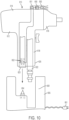
FIG. 10 is a side view of another embodiment of a power tool, a light unit, and a charger. -
FIG. 11 is a side view of another embodiment of a power tool, a light unit, and a charger. -
FIGS. 12A-12E are partially transparent, perspective views of an embodiment of a locking mechanism for a power tool and a light unit. -
FIGS. 12F and 12G are end views of the locking mechanism ofFIGS. 12A-12E . -
FIGS. 13A-13B are perspective views of another embodiment of a locking mechanism for a power tool and a light unit. -
FIGS. 13C-13G are cross-sectional views of the locking mechanism ofFIGS. 13A-13B . -
FIGS. 14A and14C are perspective views of another embodiment of a locking mechanism for a power tool and a light unit. -
FIGS. 14B and14D are end views of the locking mechanism ofFIGS. 14A and14C . -
FIG. 14E is a close up view of the locking mechanism ofFIG. 14D . -
FIGS. 14F and 14H are end views of the locking mechanism ofFIGS. 14A-14E . -
FIGS. 14G and 14I are close up views of the locking mechanism ofFIGS. 14F and 14H . -
FIGS. 15A-15H are front and side views of another embodiment of a power tool and a light unit. -
FIGS. 16A-16B are side views, partially in cross section, of another embodiment of a power tool and a light unit. -
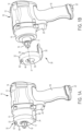
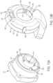
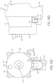
FIGS. 1A and 1B illustrate an embodiment of apower tool 10 and a removablelight unit 30. In this embodiment, thepower tool 10 is a pneumatic tool (in this case a pneumatic impact wrench) that is operable by compressed fluid, such as air. However, it should be understood that the power tool can comprise any one of numerous other types of power tools such as other pneumatic power tools (e.g., pneumatic drills, impact drivers, grinders, saws, hammers, etc.) or electric (e.g., battery or AC powered) power tools (e.g., drills, impact drivers, impact wrenches, impact drivers, saws, hammers, etc.). Thepower tool 10 includes apower tool housing 12 that includes arear portion 14 containing a motor (not shown; in this case a pneumatic motor), afront portion 16 containing a transmission and/or impact mechanism (not shown), and a smallerdiameter nose portion 17 extending forward from thefront portion 16. An output member 19 (in this case a square drive shaft) is driven by the motor and the transmission and/or impact mechanism and extends outward from thenose portion 17 of thepower tool housing 12 along an axis X. Ahandle 18 extends downward from thepower tool housing 12 and includes a switch or trigger 20 configured to be depressed by a user to control delivery of fluid to the motor (or electric power in the case of an electric tool) to control operation of thetool 10. At the bottom of thehandle 18 is anair inlet 22 configured to receive input of compressed fluid, e.g., from a compressor. - The
light unit 30 includes alight unit housing 32 having anannular portion 34 with acentral opening 36 that is concentric with the axis X. Thelight unit housing 32 also includes aflange portion 38 extending rearward from theannular portion 34 toward the tool housing, parallel to and offset from the axis X. Thelight unit housing 32 is removably coupleable to thetool housing 12 with theannular portion 34 receivable over thenose portion 17 and theflange portion 38 disposed below thefront portion 16 and adjacent theswitch 20, between thefront portion 16 and theswitch 20. Thelight unit housing 32 may be lockably coupled to thetool housing 12, e.g., according to one or more of the embodiments described below. - Referring also to
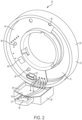
FIG. 2 , an annular or partially annular printed circuit board (PCB) 40 is received in agroove 41 in theannular portion 34 of thelight unit housing 32. As shown inFIGS. 1A and 1B , mounted to a front side of thePCB 40 is a light 42 (e.g., one or more LEDs). The LEDs are covered by a lens or transparent ortranslucent cover 44 to protect the light 42 from dust and debris. As shown inFIG. 2 , also mounted to thePCB 40 is a controller 46 (e.g., a processor, a microprocessor, and/or a digital or analog control circuit) that controls power delivery to and illumination of the light 42. ThePCB 40 may also include other electrical circuit components (e.g., a DC power supply, various resistors, capacitors, diodes, and transistors, etc.) for controlling the light 42 and other light unit components, as will be well known to one of ordinary skill in the art. ThePCB 40 may be heat staked to thelight unit housing 32 byheat meltable protrusions 48. In other embodiments, the PCB may be attached to the light unit housing by one or more screws, snaps, or rivets. - Received in a
front pocket 49 in theflange portion 38 is abattery 50 that is configured to provide electrical power to the light 42. In the illustrated embodiment, thebattery 50 is a rechargeable lithium ion pouch battery. However, it should be understood that thebattery 50 may be any type of rechargeable or non-rechargeable battery, such as a lithium-ion cylindrical cell, a nickel-cadmium battery, a coin cell, or an alkaline battery. Coupled to the PCB is a charging port 52 (e.g., a USB or micro-USB port) configured to receive a charger cable or input (e.g., a USB or micro-USB cable) for charging thebattery 50. The PCB may include a charging circuit (not shown) configured to control the charging and discharging of thebattery 50. - Referring also to
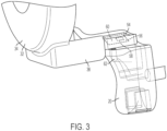
FIG. 3 , asensor 56 is received in arear pocket 54 of theflange portion 38 for sensing movement of the switch ortrigger 20. In this embodiment, thesensor 56 comprises aHall sensor 58 mounted to aHall board 60. Theswitch 20 includes a sensor target 62, e.g., a permanent magnet. Thesensor 56 is configured to sense the position of the sensor target 62 as the switch or trigger 20 is moved between a fully actuated position and a fully deactivated position. For example, thesensor 56 may generate an output electrical signal to the controller 46 corresponding to a strength of a magnetic field generated by the sensor target 62. The strength of this magnetic field may correlate with a positon of the sensor target 62 (and thus of the switch or trigger 20) relative to thesensor 56. - Referring also to
FIG. 4 , as the switch or trigger 20 is actuated or depressed, the magnet moves fromposition 1 toposition 2 and then toposition 3. Atposition 1, the light is OFF and the tool is OFF (i.e., the valve that controls fluid delivery to the motor is closed). When the switch or trigger 20 is actuated a small distance toposition 2, the valve is either not yet open, so the tool remains OFF, or is only open by a small amount, while theHall sensor 58 senses a change in the magnetic field and transmits a signal to the controller 46 indicating that the switch or trigger 20 has been actuated, and the controller 46 causes the light 42 to turn ON. When the switch is actuated a larger distance toposition 3, the light remains ON and the valve opens to deliver fluid to the motor so that the tool is also ON. The tool remains ON until the switch or trigger 20 is deactivated or released toposition 2. The light remains ON until the switch until the switch or trigger 20 is deactivated or released toposition 1. In an alternative embodiment, the controller may have or be programmed with a timer that causes the light to remain ON for a predetermined period of time after theswitch 20 has been actuated or deactivated. Examples of such timer features can be found in, e.g.,U.S. Patent Nos. 6,511,200 and9,225,275 -
FIG. 5 illustrates another embodiment of apower tool 110, similar to thepower tool 10, and alight unit 130, which may be integral with or removable from thepower tool 110. This embodiment is not according to the claimed invention. - The
power tool 110 has atool housing 112, ahandle 118, and a switch or trigger 120 for actuating the tool. Thelight unit 130 includes alight unit housing 132 coupled to the top of thetool housing 112. Thelight unit housing 132 contains a light 142 (e.g., one or more LEDs) covered by a lens or transparent ortranslucent cover 144 to protect the light 142 from dust and debris. Thelight unit housing 132 also contains a controller 146 (e.g., a processor, a microprocessor, and/or a control circuit) that controls power delivery to and illumination of the light 142 and other electrical circuit components (e.g., a DC power supply, various resistors, capacitors, diodes, and transistors, etc.) for controlling the light 142 and other light unit components, as will be well known to one of ordinary skill in the art. Received in thelight unit housing 142 is abattery 150 that is configured to provide electrical power to the light 142. In the illustrated embodiment, thebattery 150 is a rechargeable lithium ion battery. However, it should be understood that thebattery 150 may be any type of rechargeable or non-rechargeable battery, such as a lithium-ion cylindrical cell, a nickel-cadmium battery, a coin cell, or an alkaline battery. Received in thetool housing 112 and electrically in communication with thecontroller 146 is asensor 156, e.g., a Hall sensor. The switch or trigger 120 includes asensor target 162, e.g., a permanent magnet, the position of which is sensed by thesensor 156. Thesensor 156 senses movement of thesensor target 162, and thus of the switch or trigger 120, and communicates with thecontroller 146 to cause the light 142 to turn ON or OFF based on movement of the switch or trigger 120 and thesensor target 162 relative to thesensor 156, e.g., in the manner described above with respect toFIG. 4 . -
FIG. 6 illustrates another embodiment of apower tool 210, similar to thepower tools light unit 230, similar tolight unit 130, which may be integral with or removable from thepower tool 210. This embodiment is not according to the claimed invention. Thepower tool 210 has atool housing 212, ahandle 218, and aswitch 220 for actuating the tool. Thelight unit 230 includes alight unit housing 232 coupled to the top of thetool housing 212. Thelight unit housing 232 contains a light 242 (e.g., one or more LEDs) covered by a lens or transparent ortranslucent cover 244 to protect the light 242 from dust and debris. Thelight unit housing 232 also contains a controller 246 (e.g., a processor, a microprocessor, and/or a control circuit) that controls power delivery to and illumination of the light 242 and other electrical circuit components (e.g., a DC power supply, various resistors, capacitors, diodes, and transistors, etc.) for controlling the light 242 and other light unit components, as will be well known to one of ordinary skill in the art. Received in thelight unit housing 232 is abattery 250 that is configured to provide electrical power to the light 242. In the illustrated embodiment, thebattery 250 is a rechargeable lithium ion battery. However, it should be understood that thebattery 250 may be any type of rechargeable or non-rechargeable battery, such as a lithium-ion cylindrical cell, a nickel-cadmium battery, a coin cell, or an alkaline battery. Received in thetool housing 212 and electrically in communication with thecontroller 246 is asensor 256, e.g., a Hall sensor. Theswitch 220 includes asensor target 262, e.g., a permanent magnet, the position of which is sensed by thesensor 256. Thesensor 256 andsensor target 262 differ fromsensor 256 andsensor target 262 insofar as thesensor 256 is positioned behind the switch or trigger 210 and thesensor target 262 faces toward thesensor 256. Thesensor 256 senses movement of thesensor target 262, and thus of the switch or trigger 220, and communicates with a controller to cause the light 242 to turn ON or OFF based on movement of the switch or trigger 220 and thesensor target 262 relative to thesensor 256, e.g., in the manner described above with respect toFIG. 4 . - Referring to
FIGS. 7A and 7B , in another embodiment, thelight units motion sensing circuit 300 for controlling operation of thelights motion sensing circuit 300 may include amotion sensor 302, e.g., a gyroscope and/or an accelerometer, which senses motion or vibration of thepower tool motion sensor 302 may be powered by thebattery controller motion sensor 302. Via a power supply 51, 151, 251, thecontroller FIG. 7B , if themotion sensor 300 senses vibration of thetool controller motion sensing circuit 300 for controlling illumination of the light unit could either supplement or replace the control of the light unit based on movement of theswitch - Referring to
FIGS. 8A and 8B , in another embodiment, apower tool 410 and a light unit 430 (similar to thepower tools light units battery 450 in thelight unit 430. Thepower tool 410 includes apower tool housing 412 that includes arear portion 414 containing a motor, afront portion 416 containing a transmission and/or impact mechanism, and ahandle 418 extending downward from therear portion 414. Positioned at afront end 415 of therear portion 414 of thetool housing 412 are chargingterminals 453, which are electrically connected to acharging circuit 451 for charging thebattery 450. Acharger 455 includes acradle 459, one ormore charging terminals 457 and aplug 461 configured to electrically connect thecharger 455 to a source of electrical power, e.g., AC mains. Thepower tool 410 is receivable in thecharger 455 with thefront portion 416 of thetool housing 412 received in thecradle 459 at an angle, such that the chargingterminals 453 of thepower tool 410 mate with the chargingterminals 457 of thecharger 455. This provides a convenient way to recharge thebattery 450 while storing thepower tool 410. - Referring to
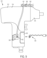
FIG. 9 , in another embodiment, apower tool 510 and a light unit 530 (similar to thepower tools light units battery 550 in thelight unit 530. Thepower tool 510 includes apower tool housing 512 that includes arear portion 514 containing a motor, afront portion 516 containing a transmission and/or impact mechanism, and ahandle 518 extending downward from therear portion 514. Thehandle 518 includes a charging port 552 (e.g., a USB or micro-USB port) that is electrically connected to acharging circuit 551 in thelight unit 550 for charging thebattery 550. When not in use, the chargingport 552 is covered by adoor 553 to protect the chargingport 552 from dust and debris. Thebattery 530 can be charged by connecting a charging terminal, cable or wire (e.g., a USB or micro-USB cable 555) to the chargingport 552, which enables the chargingcircuit 551 to control charging of thebattery 550. - Referring to
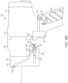
FIG. 10 , in another embodiment, apower tool 610 and a light unit 630 (similar to thepower tools light units battery 650 in thelight unit 630. Thepower tool 610 includes apower tool housing 612 that includes arear portion 614 containing a motor (not shown; in this case a pneumatic motor), afront portion 616 containing a transmission and/or impact mechanism (not shown), and ahandle 618 extending downward from therear portion 614. The handle includes anair inlet 622 and anair outlet 623. Adjacent the air outlet 623 (or the air inlet 622), at abase 625 of thehandle 618, are one ormore charging terminals 652 that are electrically connected to acharging circuit 651 for charging thebattery 650. Acharger 655 includes acradle 659 configured to receive thebase 625 of thehandle 618. Thecharger 655 has one or more charging terminals 657 and aplug 661 configured to electrically connect thecharger 655 to a source of electrical power, e.g., AC mains. Thehandle 618 of thepower tool 610 is receivable in thecradle 659 with the chargingterminals 652 of thepower tool 610 mating with the charging terminals 657 of thecharger 655. This provides a convenient way to recharge thebattery 650 while storing thepower tool 610. - Referring to
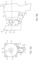
FIG. 11 , in another embodiment, apower tool 710 and a light unit 730 (similar to thepower tools light units battery 750 in thelight unit 730. Thepower tool 710 includes apower tool housing 712 that includes a rear portion 714 containing a motor (not shown; in this case a pneumatic motor), afront portion 716 containing a transmission and/or impact mechanism (not shown), and ahandle 718 extending downward from the rear portion 714. Positioned at afront end 715 of the rear portion 714 of thetool housing 712 is an annularconductive band 752, which is electrically connected to one pole (e.g., positive) of the chargingcircuit 751 for charging thebattery 750. The other pole (e.g., negative) of the chargingcircuit 751 is electrically connected to anair inlet 722, which is composed of a conductive material. Acharger 755 includes acradle 759, a firstannular charging terminal 757 configured to mate with theconductive band 752, a second pad-shapedcharging terminal 758 configured to mate with theair inlet 722, and aplug 761 configured to electrically connect thecharger 755 to a source of electrical power, e.g., AC mains. Thepower tool 710 is receivable in thecradle 759 of thecharger 755, such that theconductive band 752 mates with theannular charging terminal 757 and theair inlet 722 mates with thecharging pad 758. This provides a convenient way to recharge thebattery 750 while storing thepower tool 710. -
FIGS. 12A-12E illustrate an embodiment of a locking mechanism for removably and securely coupling ahousing 832 of a light unit 830 (similar tohousing 32 of light unit 30) to afront portion 814 andnosepiece 817 of a power tool housing 812 (similar to afront portion 16 andnosepiece 17 of power tool housing 12) using a bayonet-style attachment. Thenosepiece 817 includes aradial projection 824, an annularouter rib support 826, and alocking recess 828. Thelight unit housing 832 includes anannular wall portion 834, acentral opening 835 defining an interior L-shapedslot 836, and a V-shapedleaf spring 838 having twolegs 837 joined at acurved vertex 839. As shown inFIGS. 12B-12C , to install thelight unit 830 on thepower tool housing 812, theannular wall portion 834 of thelight unit housing 832 is received in an axial direction A over theouter rib support 826 with theradial projection 824 received in anaxial portion 840 of the L-shapedslot 836. As shown inFIGS. 12D, 12E ,12F, and 12G , to secure thelight unit 830 on thepower tool housing 812, thelight unit housing 832 is rotated in a clockwise direction CW relative to thepower tool housing 812. This causes theradial projection 824 to be received in acircumferential portion 842 of the L-shapedslot 836, while, at the same time, thecurved vertex 839 of theleaf spring 838 engages thelocking recess 828. As shown inFIG. 12F , to remove thelight unit 830 from thepower tool housing 812, thelight unit housing 832 is rotatable in a counterclockwise direction CCW to an unlocked position where theleaf spring 838 is disengaged from the lockingrecess 840 and theradial projection 824 is aligned with theaxial portion 840 of the L-shapedslot 836 to facilitate removing thelight unit housing 832 from thepower tool housing 812. -
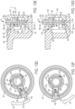
FIGS. 13A-13G illustrate another embodiment of a locking mechanism for removably and securely coupling ahousing 932 of a light unit 930 (similar tohousing 32 of light unit 30) to afront portion 914 andnosepiece 917 of a power tool housing 912 (similar to afront portion 16 andnosepiece 17 of power tool housing 12) using a bayonet-style attachment. Thenosepiece 917 includes a plurality ofradial projections 924, an annularouter support rib 926, and alocking recess 928 defined in thesupport rib 926. Thelight unit housing 932 includes anannular wall portion 934 carrying a light 942 with atransparent cover 944. Theannular wall portion 934 has an innerannular wall 940 that defines acentral opening 935. A plurality of L-shaped slots 936 (one of which is shown) are also defined in the innerannular wall 940. Each L-shapedslot 936 includes anaxial portion 937 and acircumferential portion 939. Theannular wall portion 934 also has an outerannular wall 941 carries alocking button 946 that is biased radially outwardly by acompression spring 948. Thelocking button 946 includes awide base portion 954, a narrowtop portion 956, and a recessedportion 950 with a rampedsurface 952 connecting thebase portion 954 to thetop portion 956. -
FIGS. 13C-13G illustrate installation and locking of thelight unit 930 on thepower tool housing 912. As shown inFIG. 13C , thelight unit housing 932 is rotationally positioned relative to thepower tool housing 912 so that theradial projections 924 on thenosepiece 917 are aligned with theaxial portions 937 of the L-shapedslots 936 on the innerannular wall 940 of thelight unit housing 932. As shown inFIGS. 13D-13E , thelight unit housing 932 is moved in a direction A axially toward thepower tool housing 912, so that theradial projections 924 are received in theaxial portions 937 of the L-shapedslots 936 and the outerannular wall 941 is received around thesupport rib 926. At the same time, thesupport rib 926 engages the rampedsurface 952 in thelocking button 946, which pushes the locking button in a radially inward direction RI against the force of thespring 948. As shown inFIGS. 13F-13G , the user then rotates thelight unit housing 932 in a clockwise direction CW so that theradial projections 924 are received in thecircumferential portions 939 of the L-shapedslots 936. At the same time, the recessedportion 950 of thelocking button 946 is aligned with thelocking recess 928 in thesupport rib 926, removing the force that thesupport rib 926 exerts on the rampedsurface 952 of thelocking button 946. The biasing force of thespring 948 causes thelocking button 946 to move in a radially outward direction RO so that thebase portion 954 of thelocking button 946 is caught in thelocking recess 928 of thesupport rib 926, locking thelight unit housing 932 on thepower tool housing 912. To remove thelight unit housing 932, the user depresses thelocking button 946 in the radial inward direction RI against the force of thespring 948 and rotates thelight unit housing 932 in a counterclockwise direction until theradial projections 924 are aligned with theaxial portions 937 of the L-shapedslots 936. The user can then pull thelight unit housing 932 axially away from thepower tool housing 912 to remove thelight unit housing 932 from thepower tool housing 912. -
FIGS. 14A-14I illustrate another embodiment of a locking mechanism for removably and securely coupling ahousing 1032 of a light unit 1030 (similar tohousing 32 of light unit 30) to afront portion 1014 andnosepiece 1017 of a power tool housing 1012 (similar to afront portion 16 andnosepiece 17 of power tool housing 12) using a bayonet-style attachment. Thenosepiece 1017 includes a plurality ofradial projections 1024, an annularouter rib support 1026, and a plurality of locking features 1028 on therib support 1026. As shown inFIG. 14E , eachlocking feature 1028 includes an elongatedcircumferential receiving recess 1040, a shortercircumferential locking recess 1042 and atapered protrusion 1044 between the receivingrecess 1040 and thelocking recess 1042. Thelight unit housing 1032 includes anannular wall portion 1034 with acentral opening 1035 defining a plurality of interior L-shapedslots 1036 defined in thecentral opening 1035 of theannular wall portion 1034. The interior of theannular wall portion 1034 also defines a plurality ofresilient locking tabs 1038. As shown inFIGS. 14F and 14G , to install thelight unit housing 1032 on thepower tool housing 1012, theannular wall portion 1034 of thelight unit housing 1032 is received in an axial direction over theouter rib support 1026 with theradial projections 1024 received inaxial portions 1037 of the L-shapedslots 1036 and with lockingtabs 1038 received in the receiving recesses 1040. As shown inFIGS. 14H and 14I , to secure thelight unit housing 1032 on thepower tool housing 1012, thelight unit housing 1032 is rotated in a clockwise direction CW relative to thepower tool housing 1012. This causes theradial projections 1024 to be received incircumferential portions 1039 of the L-shapedslots 1036, while, at the same time, the lockingtabs 1038 deflect as they ride over the taperedprotrusions 1044 until they are received in the locking recesses 1042. As shown inFIGS. 14F and 14G , thelight unit housing 1032 is rotatable back to the unlocked position by rotating it in a counterclockwise direction CCW so that thelocking tabs 1038 ride over the taperedprotrusions 1044, causing theannular wall portion 1034 to deflect until thelocking tabs 1038 are received in the receivingrecesses 1040 and theradial projection 1024 is aligned with theaxial portion 1037 of the L-shapedslot 1036. At this point, thelight unit housing 1032 can be pulled axially off of thepower tool housing 1012 to remove thelight unit housing 1032 from thepower tool housing 1012. -
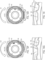
FIGS. 15A-15G illustrate another embodiment of a power tool 1110 (e.g., a pneumatic or electric power tool) and aremovable light unit 1130, similar to the previously described embodiments of power tools and light units. Thepower tool 1110 andlight unit 1130 differs from the previously described embodiments in the design of a sensor and sensor target for causing thelight unit 1130 to turn ON when the switch or trigger of thepower tool 1110 is actuated. In this embodiment, thepower tool 1110 includes apower tool housing 1112 that includes arear portion 1114 containing a motor (not shown), afront portion 1116 containing a transmission and/or impact mechanism (not shown), and a smallerdiameter nose portion 1117 extending forward from thefront portion 1116. An output member 1119 (in this case a square drive shaft) is driven by the motor and the transmission and/or impact mechanism and extends outward from thenose portion 1117 of thepower tool housing 1112 along an axis X. Ahandle 1118 extends downward from thepower tool housing 1112 and includes a switch ortrigger 1120 configured to be depressed by a user to control the motor. - The
light unit 1130 includes alight unit housing 1132 having anannular portion 1134 with a central opening 1136 concentric with the axis X, and aflange portion 1138 extending rearward from theannular portion 1134 toward thetool housing 1112, parallel to and offset from the axis X. Received in theflange portion 1138 are abattery 1161 and a controller 1146 (e.g., a control circuit, a microprocessor, or a microcontroller). Received in theannular portion 1134 is a light 1142 that is electrically connected to thebattery 1161 and thecontroller 1146. Thelight unit housing 1132 is removably coupleable to thetool housing 1112 with theannular portion 1134 receivable over thenose portion 1117 and theflange portion 1138 disposed below thefront portion 1116 and adjacent theswitch 1120, between thefront portion 1116 and the switch ortrigger 1120. Thelight unit housing 1132 may be lockably coupled to thetool housing 1112, e.g., according to one or more of the embodiments described above. - A sensor in the form of a toggle or
pressure switch 1156 is located in theflange portion 1138 and is coupled to thecontroller 1146. The toggle orpressure switch 1156 is configured to sense movement of the switch ortrigger 1120 of thepower tool 1110. The switch ortrigger 1120 includes a sensor target in the form of arecess 1162 that receives anarm 1157 of the toggle orpressure switch 1156. Therecess 1162 is open to one side of the switch ortrigger 1120 to facilitate receiving thearm 1157 in therecess 1162 when thelight unit housing 1132 is installed on thepower tool housing 1112 using one of the bayonet-type connections described above. As shown inFIGS. 15A-15D , when thelight unit housing 1132 is moved axially toward thepower tool housing 1112, thearm 1157 is rotationally misaligned with the switch ortrigger 1120. As shown inFIGS. 15E-15F , when thelight unit housing 1132 is the rotated in a clockwise direction CW to lock thelight unit housing 1132 on thepower tool housing 1112, thearm 1157 of the toggle orpressure switch 1156 slides into therecess 1162 in the switch ortrigger 1120. - As shown in
FIGS. 15G-15H , the toggle orpressure switch 1156 is configured to sense the position of the switch ortrigger 1120 by moving axially toward thetool housing 1112 as the switch ortrigger 1120 is moved from a fully deactivated position to a partially or fully activated position. Depressing the switch ortrigger 1120 causes thearm 1157 to pivot toward thepower tool housing 1112, which causes the toggle orpressure switch 1156 to close. In one embodiment, when the switch ortrigger 1120 is actuated a small distance, the power tool motor remains OFF or rotates at a very low speed, while the toggle orpressure switch 1156 closes, and thecontroller 1146 causes the light 1142 to turn ON. When the switch ortrigger 1120 is actuated a larger distance, the toggle orpressure switch 1156 remains closed so that the light 1142 remains ON, while the motor is activated to run at a faster or full speed. The motor and the light remain ON until the switch ortrigger 1120 is deactivated or released. In an alternative embodiment, thecontroller 1146 may have or be programmed with a timer that causes the light to remain ON for a predetermined period of time after theswitch 1120 has been actuated or deactivated. Examples of such timer features can be found in, e.g.,U.S. Patent Nos. 6,511,200 and9,225,275 -
FIGS. 16A-16B illustrate another embodiment of a power tool 1210 (e.g., a pneumatic or electric power tool) and aremovable light unit 1230, similar to the previously described embodiments of power tools and light units. Thepower tool 1210 andlight unit 1230 differ from the previously described embodiments in the design of a sensor and sensor target for causing thelight unit 1230 to turn ON when the switch or trigger of thepower tool 1210 is actuated. In this embodiment, thepower tool 1210 includes apower tool housing 1212 that includes arear portion 1214 containing a motor (not shown), afront portion 1216 containing a transmission and/or impact mechanism (not shown), and a smaller diameter nose portion (not shown) extending forward from thefront portion 1216. An output member (not shown, e.g., a square drive shaft) is driven by the motor and the transmission and/or impact mechanism and extends outward from the nose portion of thepower tool housing 1212 along an axis X. Ahandle 1218 extends downward from thepower tool housing 1212 and includes aninlet passageway 1219 for delivering compressed air to the motor. A switch ortrigger 1220 is coupled to thehandle 1218 and is linked to avalve 1221 in theinlet passageway 1219. As shown inFIG. 16B , the switch ortrigger 1220 can be actuated or depressed, which opens thevalve 1221 to deliver air to the motor. - The
light unit 1230 includes a light unit housing 1232 having anannular portion 1234 concentric with the axis X, and aflange portion 1238 extending rearward from theannular portion 1234 toward thetool housing 1212, parallel to and offset from the axis X. Received in theflange portion 1238 are abattery 1261, a controller 1246 (e.g., a control circuit, a microprocessor, or a microcontroller), and a make or breakelectrical switch 1247. Received in theannular portion 1234 is a light 1242 that is electrically connected to thebattery 1261 and thecontroller 1246 via the make or breakswitch 1247. The light unit housing 1232 is removably coupleable to thetool housing 1212 with theannular portion 1234 receivable over the nose portion and theflange portion 1238 disposed below thefront portion 1216 and adjacent the switch ortrigger 1220. The light unit housing 1232 may be lockably coupled to thetool housing 1212, e.g., according to one or more of the embodiments described above. - A sensor in the form of a toggle or
pressure switch 1256 extends rearward from theflange portion 1238 and is biased in the rearward direction by acompression spring 1258. Thetoggle switch 1256 is coupled to the make or breakswitch 1247, such that rearward movement of the toggle orpressure switch 1256 causes the make or breakswitch 1247 to close. The switch ortrigger 1220 includes a sensor target in the form of aprotrusion 1262 on the front of the toggle orpressure switch 1256 that abuts the toggle orpressure switch 1256. The toggle orpressure switch 1256 is configured to sense the position of the switch ortrigger 1220 by moving axially toward thetool housing 1212, under the biasing force ofcompression spring 1258, as the switch ortrigger 1220 is moved from a deactivated position (shown inFIG. 16A ) to a partially or fully activated position (shown inFIG. 16B ). Depressing the switch ortrigger 1220 allows the toggle orpressure switch 1256 to move axially toward thepower tool housing 1212, which causes the make or breakswitch 1247 to close. In one embodiment, when the switch ortrigger 1220 is actuated a small distance, the power tool motor remains OFF or rotates at a very low speed, while the toggle orpressure switch 1256 moves enough to allow the make or breakswitch 1247 to close, and thecontroller 1246 causes the light 1242 to turn ON. When the switch ortrigger 1220 is actuated a larger distance, the toggle orpressure switch 1256 remains biased rearward so that the make or breakswitch 1247 is closed, and the light 1242 remains ON, while the motor is activated to run at a faster or full speed. The motor and the light 1242 remain ON until the switch ortrigger 1220 is deactivated or released, pushing the toggle orpressure switch 1262 axially forward against the force ofcompression spring 1258, causing the make or breakswitch 1247 to open. In an alternative embodiment, thecontroller 1246 may have or be programmed with a timer that causes the light 1242 to remain ON for a predetermined period of time after theswitch 1220 has been actuated or deactivated. Examples of such timer features can be found in, e.g.,U.S. Patent Nos. 6,511,200 and9,225,275 - Example embodiments have been provided so that this disclosure will be thorough, and to fully convey the scope to those who are skilled in the art. Numerous specific details are set forth such as examples of specific components, devices, and methods, to provide a thorough understanding of embodiments of the present disclosure. It will be apparent to those skilled in the art that specific details need not be employed, that example embodiments may be embodied in many different forms and that neither should be construed to limit the scope of the disclosure. In some example embodiments, well-known processes, well-known device structures, and well-known technologies are not described in detail.
- The terminology used herein is for the purpose of describing particular example embodiments only and is not intended to be limiting. As used herein, the singular forms "a," "an," and "the" may be intended to include the plural forms as well, unless the context clearly indicates otherwise. The terms "comprises," "comprising," "including," and "having," are inclusive and therefore specify the presence of stated features, integers, steps, operations, elements, and/or components, but do not preclude the presence or addition of one or more other features, integers, steps, operations, elements, components, and/or groups thereof. The method steps, processes, and operations described herein are not to be construed as necessarily requiring their performance in the particular order discussed or illustrated, unless specifically identified as an order of performance. It is also to be understood that additional or alternative steps may be employed.
- When an element or layer is referred to as being "on," "engaged to," "connected to," or "coupled to" another element or layer, it may be directly on, engaged, connected or coupled to the other element or layer, or intervening elements or layers may be present. In contrast, when an element is referred to as being "directly on," "directly engaged to," "directly connected to," or "directly coupled to" another element or layer, there may be no intervening elements or layers present. Other words used to describe the relationship between elements should be interpreted in a like fashion (e.g., "between" versus "directly between," "adjacent" versus "directly adjacent," etc.). As used herein, the term "and/or" includes any and all combinations of one or more of the associated listed items.
- Although the terms first, second, third, etc. may be used herein to describe various elements, components, regions, layers and/or sections, these elements, components, regions, layers and/or sections should not be limited by these terms. These terms may be only used to distinguish one element, component, region, layer or section from another region, layer or section. Terms such as "first," "second," and other numerical terms when used herein do not imply a sequence or order unless clearly indicated by the context. Thus, a first element, component, region, layer or section discussed below could be termed a second element, component, region, layer or section without departing from the teachings of the example embodiments.
- Terms of degree such as "generally," "substantially," "approximately," and "about" may be used herein when describing the relative positions, sizes, dimensions, or values of various elements, components, regions, layers and/or sections. These terms mean that such relative positions, sizes, dimensions, or values are within the defined range or comparison (e.g., equal or close to equal) with sufficient precision as would be understood by one of ordinary skill in the art in the context of the various elements, components, regions, layers and/or sections being described.
- Numerous modifications may be made to the exemplary implementations described above. These and other implementations are within the scope of the following claims.
Claims (13)
- A light unit (30) for a power tool (10) having a tool housing (12), a switch (20), and an output member (19) that extends along an axis X, said light unit (30) comprising:a light unit housing (32) removably coupleable to the tool housing (12);a light (42) disposed in the light unit housing (32); anda battery (50) disposed within the light unit housing (32), and configured to provide electrical power to the light (42); andcharacterized in that the light unit (30) further includes a sensor (56) disposed in the light unit housing (32) and configured to sense movement of the switch (20), which actuates the power tool (10) to perform an operation; anda controller (46) coupled to each of the sensor (56), the battery (50), and the light (42), and wherein the controller (46) is configured to discharge power from the battery (50) thereby causing the light to turn ON when the sensor (56) senses movement of the switch (20) of the power tool (10).
- The light unit (30) of claim 1, wherein the light unit housing (32) is removably coupled to the tool housing (12) by a bayonet connection so that the light unit housing (32) is rotatable between an unlocked position and a locked position.
- The light unit (30) of claim 2, wherein the light unit housing (32) further comprises a locking mechanism configured to maintain the light unit housing (32) in the locked position.
- The light unit (30) of claim 3, wherein the locking mechanism comprises at least one of a leaf spring (838), a locking tab (1038), and a locking button (946) configured to be received in a recess.
- The light unit (30) of claim 1, wherein the sensor (56) comprises a Hall sensor (58) configured to sense movement of a magnet (62) coupled to the switch (20) of the power tool (10).
- The light unit of (30) claim 1, wherein the sensor (56) comprises a toggle switch (1256) or a pressure switch (1256) configured to sense movement of the switch (20) of the power tool (10).
- The light unit (30) of claim 1, wherein the controller (46) includes a timer configured to keep the light ON for a predetermined time period after the switch (20) has been actuated or deactivated.
- The light unit (30) of claim 1, further comprising a USB port (52) or one or more electrical contacts configured to provide power for recharging the battery (50).
- A power tool (10) comprising:a tool housing (12);a motor disposed in the tool housing (12);a switch (20) coupled to the tool housing (12) and configured to control actuation of the motor;a sensor target (62) coupled for movement with the switch (20); andcharacterized in that said power tool further includes a light unit (30) according to claim 1.
- The power tool (10) of claim 9, wherein the light unit housing (32) is removably coupled to the tool housing (12) by a bayonet connection.
- The power tool (10) of claim 9, wherein the sensor (56) comprises a Hall sensor (58) and the sensor target (62) comprises a magnet.
- The power tool (10) of claim 9, wherein the sensor (56) comprises a toggle switch (1256) or a pressure switch (1256) and the sensor target (62) comprises a protrusion (1262) of the switch (20) that engages the toggle switch (1256) or the pressure switch (1256).
- The power tool of claim 9, wherein said power tool is pneumatic, and wherein said motor is pneumatic, and wherein the switch (20) controls actuation of the pneumatic motor by controlling the delivery of fluid thereto.
Applications Claiming Priority (2)
| Application Number | Priority Date | Filing Date | Title |
|---|---|---|---|
| US15/373,965 US10207380B2 (en) | 2016-12-09 | 2016-12-09 | Power tool and light unit |
| PCT/US2017/065146 WO2018106936A1 (en) | 2016-12-09 | 2017-12-07 | Power tool and light unit |
Publications (3)
| Publication Number | Publication Date |
|---|---|
| EP3551389A1 EP3551389A1 (en) | 2019-10-16 |
| EP3551389A4 EP3551389A4 (en) | 2020-08-05 |
| EP3551389B1 true EP3551389B1 (en) | 2024-04-24 |
Family
ID=62488301
Family Applications (1)
| Application Number | Title | Priority Date | Filing Date |
|---|---|---|---|
| EP17878895.6A Active EP3551389B1 (en) | 2016-12-09 | 2017-12-07 | Power tool and light unit |
Country Status (4)
| Country | Link |
|---|---|
| US (1) | US10207380B2 (en) |
| EP (1) | EP3551389B1 (en) |
| CA (1) | CA3046484A1 (en) |
| WO (1) | WO2018106936A1 (en) |
Families Citing this family (29)
| Publication number | Priority date | Publication date | Assignee | Title |
|---|---|---|---|---|
| EP3090838B1 (en) | 2011-05-19 | 2020-06-17 | Black & Decker Inc. | Power tool with force sensing electronic clutch |
| CN107921613B (en) * | 2015-06-02 | 2020-11-06 | 米沃奇电动工具公司 | Multi-speed power tool with electronic clutch |
| US10615670B2 (en) | 2015-06-05 | 2020-04-07 | Ingersoll-Rand Industrial U.S., Inc. | Power tool user interfaces |
| WO2016196899A1 (en) | 2015-06-05 | 2016-12-08 | Ingersoll-Rand Company | Power tool housings |
| WO2016196984A1 (en) | 2015-06-05 | 2016-12-08 | Ingersoll-Rand Company | Power tools with user-selectable operational modes |
| WO2016196979A1 (en) | 2015-06-05 | 2016-12-08 | Ingersoll-Rand Company | Impact tools with ring gear alignment features |
| DE102016125435A1 (en) * | 2016-12-22 | 2018-06-28 | C. & E. Fein Gmbh | Hand tool |
| SE1850881A1 (en) * | 2018-07-11 | 2020-01-12 | Husqvarna Ab | Power tool |
| US11445702B2 (en) | 2018-09-19 | 2022-09-20 | Lg Electronics Inc. | Pet care device |
| US11083910B2 (en) * | 2018-09-19 | 2021-08-10 | Lg Electronics Inc. | Pet care device and method for controlling pet care device |
| WO2020182273A1 (en) * | 2019-03-08 | 2020-09-17 | Mirka Oy | Trigger apparatus for powered device, powered device, and method of controlling an operation of a powered device |
| EP3822031A1 (en) * | 2019-11-14 | 2021-05-19 | Hilti Aktiengesellschaft | Method for controlling and regulating a machine tool |
| CN211119067U (en) * | 2019-12-06 | 2020-07-28 | 台州百斯威机械有限公司 | Lamp body device for maintenance tool |
| DE102020201946A1 (en) | 2020-02-17 | 2021-08-19 | Robert Bosch Gesellschaft mit beschränkter Haftung | Hand machine tool with a work area lighting |
| CN111590524B (en) * | 2020-06-11 | 2024-11-05 | 浙江德硕科技股份有限公司 | Head and body quick-change structure of multifunctional power tool and multifunctional power tool |
| CN212653400U (en) * | 2020-06-12 | 2021-03-05 | 米沃奇电动工具公司 | Swing power tool with lighting assembly |
| US11213937B1 (en) * | 2020-09-22 | 2022-01-04 | Snap-On Incorporated | Tool illumination source |
| US20220167982A1 (en) * | 2020-12-02 | 2022-06-02 | Ethicon Llc | Surgical instruments with electrical connectors for power transmission across sterile barrier |
| US11672067B2 (en) | 2021-01-29 | 2023-06-06 | Snap-On Incorporated | Circuit board with sensor controlled lights and end-to-end connection |
| US11622764B2 (en) | 2021-04-27 | 2023-04-11 | Lexington Medical, Inc. | Surgical handle assembly |
| US11835217B2 (en) | 2021-05-06 | 2023-12-05 | Black & Decker Inc. | Light emitting assembly for a power tool |
| US20250009352A1 (en) * | 2021-06-07 | 2025-01-09 | Lexington Medical, Inc. | Motorized surgical handle assembly |
| US11897097B1 (en) * | 2022-08-15 | 2024-02-13 | Caterpillar Paving Products Inc. | Rotor bit extraction tool with a lighting unit |
| JP2024059481A (en) * | 2022-10-18 | 2024-05-01 | 株式会社マキタ | Electric work machine |
| US12539590B2 (en) * | 2023-01-12 | 2026-02-03 | Milwaukee Electric Tool Corporation | Printed circuit board assembly with multiple conduction paths |
| US12569971B2 (en) | 2023-01-27 | 2026-03-10 | Black & Decker Inc. | Angled tool accessory holder |
| DE102024102589A1 (en) * | 2023-02-08 | 2024-08-08 | Husqvarna Ab | Hand-held powered tool |
| DE102023203959A1 (en) * | 2023-04-28 | 2024-10-31 | Festool Gmbh | Lighting system for a motor-driven hand-held machine tool and machine tool assembly |
| US12533784B2 (en) * | 2023-05-30 | 2026-01-27 | Milwaukee Electric Tool Corporation | Shadowless lighting design for a power tool |
Family Cites Families (24)
| Publication number | Priority date | Publication date | Assignee | Title |
|---|---|---|---|---|
| US2855679A (en) | 1955-11-08 | 1958-10-14 | Howard G Gibble | Gage attachment for drills |
| US4078869A (en) | 1977-01-17 | 1978-03-14 | Honeycutt Damon P | Two-way right angle drill |
| US4480295A (en) | 1983-03-21 | 1984-10-30 | Shuster Frank J | Work surface light |
| US6206538B1 (en) * | 1999-08-30 | 2001-03-27 | David B. Lemoine | Miser light for cordless battery operated hand tools |
| US6443675B1 (en) * | 2000-02-17 | 2002-09-03 | Roto Zip Tool Corporation | Hand-held power tool |
| JP2001300867A (en) * | 2000-04-21 | 2001-10-30 | Makita Corp | Adapter for power tool |
| US6511201B1 (en) * | 2001-12-05 | 2003-01-28 | Dale K Elrod | Air gun with integral air powered light |
| JP2003211374A (en) * | 2002-01-21 | 2003-07-29 | Hitachi Koki Co Ltd | Electric tool |
| US6921235B2 (en) | 2003-01-13 | 2005-07-26 | Sean & Stephen Corp. | Laser centering mechanism of a drilling machine |
| US20050152755A1 (en) | 2004-01-14 | 2005-07-14 | Sean Chen | Laser device for helping an intended point on a work piece located exactly opposite the sharp point of a drill |
| GB2420400B (en) * | 2004-11-17 | 2007-05-02 | Black & Decker Inc | Power tool with illumination device |
| US20060176682A1 (en) * | 2005-02-09 | 2006-08-10 | Mobiletron Electronics Co., Ltd. | Power hand tool |
| DE102006045157B4 (en) | 2006-09-25 | 2020-06-18 | Robert Bosch Gmbh | Hand tool |
| US20080266845A1 (en) | 2007-04-25 | 2008-10-30 | Unity Opto Technology Co., Ltd. | Auxiliary lighting device |
| JP5047853B2 (en) * | 2008-03-26 | 2012-10-10 | 株式会社マキタ | Electric tool |
| EP2199024B1 (en) | 2008-12-16 | 2018-09-05 | Robert Bosch Gmbh | Hand-held power tool |
| US8317350B2 (en) | 2009-02-25 | 2012-11-27 | Black & Decker Inc. | Power tool with a light for illuminating a workpiece |
| US8328381B2 (en) | 2009-02-25 | 2012-12-11 | Black & Decker Inc. | Light for a power tool and method of illuminating a workpiece |
| US20110058356A1 (en) | 2009-02-25 | 2011-03-10 | Black & Decker Inc. | Power tool with light emitting assembly |
| US9722334B2 (en) * | 2010-04-07 | 2017-08-01 | Black & Decker Inc. | Power tool with light unit |
| US9225275B2 (en) * | 2010-04-07 | 2015-12-29 | Black & Decker Inc. | Power tool with light unit |
| US9028088B2 (en) * | 2010-09-30 | 2015-05-12 | Black & Decker Inc. | Lighted power tool |
| DE102012209916A1 (en) | 2012-06-13 | 2013-12-19 | Hilti Aktiengesellschaft | machine tool |
| US9682466B2 (en) * | 2014-09-10 | 2017-06-20 | Elmer A. Wessel | Ring light |
-
2016
- 2016-12-09 US US15/373,965 patent/US10207380B2/en active Active
-
2017
- 2017-12-07 EP EP17878895.6A patent/EP3551389B1/en active Active
- 2017-12-07 CA CA3046484A patent/CA3046484A1/en active Pending
- 2017-12-07 WO PCT/US2017/065146 patent/WO2018106936A1/en not_active Ceased
Also Published As
| Publication number | Publication date |
|---|---|
| US20180161951A1 (en) | 2018-06-14 |
| EP3551389A4 (en) | 2020-08-05 |
| CA3046484A1 (en) | 2018-06-14 |
| WO2018106936A1 (en) | 2018-06-14 |
| US10207380B2 (en) | 2019-02-19 |
| EP3551389A1 (en) | 2019-10-16 |
Similar Documents
| Publication | Publication Date | Title |
|---|---|---|
| EP3551389B1 (en) | Power tool and light unit | |
| US11938611B2 (en) | Portable power tool having an electromotive direct drive | |
| US20210170563A1 (en) | Power tool having interchangeable tool heads | |
| US10974381B2 (en) | System at least comprising an electronically commutated electric motor of a defined construction size, and a rechargeable battery of at least one voltage class | |
| CN111421511B (en) | Electric tool | |
| US7557534B2 (en) | Power tool, battery, charger and method of operating the same | |
| US7649337B2 (en) | Power tool including a fuel gauge and method of operating the same | |
| CN112706043B (en) | Power Tools | |
| US20210228041A1 (en) | Rechargeable cleaner | |
| EP3386683B1 (en) | Rotary power tool lighting system | |
| EP3113912A1 (en) | Improvements to portable power supply | |
| US12122016B2 (en) | Grinding head and brush ring for long rod grinding machine | |
| TW201907267A (en) | Adapters for communication between power tools | |
| US20080214097A1 (en) | Handheld electric grinder | |
| JP7103429B2 (en) | Battery pack and electrical equipment using it | |
| CN119159542A (en) | Handheld power tool including a light emitting unit and light emitting unit therefor | |
| US12224610B2 (en) | Battery-operated device including an electromechanical interface for an interchangeable drive unit | |
| US20240051110A1 (en) | Rotary Tool and Standby Base | |
| CN220051718U (en) | electrical tools | |
| US20090207011A1 (en) | Auto-charging alert device for rotatable pneumatic object | |
| EP4243239A1 (en) | Charger and battery for cordless appliance | |
| US20260054364A1 (en) | Power tool | |
| WO2016116064A1 (en) | Power device, electric power tool and electric power tool system | |
| CN211966891U (en) | Electric tool | |
| JP2021088034A (en) | Rod type grinding machine |
Legal Events
| Date | Code | Title | Description |
|---|---|---|---|
| STAA | Information on the status of an ep patent application or granted ep patent |
Free format text: STATUS: THE INTERNATIONAL PUBLICATION HAS BEEN MADE |
|
| PUAI | Public reference made under article 153(3) epc to a published international application that has entered the european phase |
Free format text: ORIGINAL CODE: 0009012 |
|
| STAA | Information on the status of an ep patent application or granted ep patent |
Free format text: STATUS: REQUEST FOR EXAMINATION WAS MADE |
|
| 17P | Request for examination filed |
Effective date: 20190702 |
|
| AK | Designated contracting states |
Kind code of ref document: A1 Designated state(s): AL AT BE BG CH CY CZ DE DK EE ES FI FR GB GR HR HU IE IS IT LI LT LU LV MC MK MT NL NO PL PT RO RS SE SI SK SM TR |
|
| AX | Request for extension of the european patent |
Extension state: BA ME |
|
| RIN1 | Information on inventor provided before grant (corrected) |
Inventor name: MORELAND, FLOYD E. Inventor name: MUTI, DAVID Inventor name: BILLINGS, ROSS A Inventor name: HEGARTY, DANIEL A.O. Inventor name: PATEL, SANDIP Inventor name: WANG, KEVIN Inventor name: BEERS, DAVID Inventor name: BIRKEL, ANDREW |
|
| DAV | Request for validation of the european patent (deleted) | ||
| DAX | Request for extension of the european patent (deleted) | ||
| A4 | Supplementary search report drawn up and despatched |
Effective date: 20200707 |
|
| RIC1 | Information provided on ipc code assigned before grant |
Ipc: B25B 23/18 20060101AFI20200701BHEP |
|
| STAA | Information on the status of an ep patent application or granted ep patent |
Free format text: STATUS: EXAMINATION IS IN PROGRESS |
|
| 17Q | First examination report despatched |
Effective date: 20230622 |
|
| GRAP | Despatch of communication of intention to grant a patent |
Free format text: ORIGINAL CODE: EPIDOSNIGR1 |
|
| STAA | Information on the status of an ep patent application or granted ep patent |
Free format text: STATUS: GRANT OF PATENT IS INTENDED |
|
| GRAS | Grant fee paid |
Free format text: ORIGINAL CODE: EPIDOSNIGR3 |
|
| INTG | Intention to grant announced |
Effective date: 20240221 |
|
| GRAA | (expected) grant |
Free format text: ORIGINAL CODE: 0009210 |
|
| STAA | Information on the status of an ep patent application or granted ep patent |
Free format text: STATUS: THE PATENT HAS BEEN GRANTED |
|
| P01 | Opt-out of the competence of the unified patent court (upc) registered |
Effective date: 20240228 |
|
| AK | Designated contracting states |
Kind code of ref document: B1 Designated state(s): AL AT BE BG CH CY CZ DE DK EE ES FI FR GB GR HR HU IE IS IT LI LT LU LV MC MK MT NL NO PL PT RO RS SE SI SK SM TR |
|
| REG | Reference to a national code |
Ref country code: GB Ref legal event code: FG4D |
|
| REG | Reference to a national code |
Ref country code: CH Ref legal event code: EP |
|
| REG | Reference to a national code |
Ref country code: DE Ref legal event code: R096 Ref document number: 602017081393 Country of ref document: DE |
|
| REG | Reference to a national code |
Ref country code: IE Ref legal event code: FG4D |
|
| REG | Reference to a national code |
Ref country code: LT Ref legal event code: MG9D |
|
| REG | Reference to a national code |
Ref country code: NL Ref legal event code: MP Effective date: 20240424 |
|
| REG | Reference to a national code |
Ref country code: AT Ref legal event code: MK05 Ref document number: 1679108 Country of ref document: AT Kind code of ref document: T Effective date: 20240424 |
|
| PG25 | Lapsed in a contracting state [announced via postgrant information from national office to epo] |
Ref country code: NL Free format text: LAPSE BECAUSE OF FAILURE TO SUBMIT A TRANSLATION OF THE DESCRIPTION OR TO PAY THE FEE WITHIN THE PRESCRIBED TIME-LIMIT Effective date: 20240424 |
|
| PG25 | Lapsed in a contracting state [announced via postgrant information from national office to epo] |
Ref country code: NL Free format text: LAPSE BECAUSE OF FAILURE TO SUBMIT A TRANSLATION OF THE DESCRIPTION OR TO PAY THE FEE WITHIN THE PRESCRIBED TIME-LIMIT Effective date: 20240424 |
|
| PG25 | Lapsed in a contracting state [announced via postgrant information from national office to epo] |
Ref country code: IS Free format text: LAPSE BECAUSE OF FAILURE TO SUBMIT A TRANSLATION OF THE DESCRIPTION OR TO PAY THE FEE WITHIN THE PRESCRIBED TIME-LIMIT Effective date: 20240824 |
|
| PG25 | Lapsed in a contracting state [announced via postgrant information from national office to epo] |
Ref country code: BG Free format text: LAPSE BECAUSE OF FAILURE TO SUBMIT A TRANSLATION OF THE DESCRIPTION OR TO PAY THE FEE WITHIN THE PRESCRIBED TIME-LIMIT Effective date: 20240424 |
|
| PG25 | Lapsed in a contracting state [announced via postgrant information from national office to epo] |
Ref country code: HR Free format text: LAPSE BECAUSE OF FAILURE TO SUBMIT A TRANSLATION OF THE DESCRIPTION OR TO PAY THE FEE WITHIN THE PRESCRIBED TIME-LIMIT Effective date: 20240424 Ref country code: FI Free format text: LAPSE BECAUSE OF FAILURE TO SUBMIT A TRANSLATION OF THE DESCRIPTION OR TO PAY THE FEE WITHIN THE PRESCRIBED TIME-LIMIT Effective date: 20240424 |
|
| PG25 | Lapsed in a contracting state [announced via postgrant information from national office to epo] |
Ref country code: GR Free format text: LAPSE BECAUSE OF FAILURE TO SUBMIT A TRANSLATION OF THE DESCRIPTION OR TO PAY THE FEE WITHIN THE PRESCRIBED TIME-LIMIT Effective date: 20240725 |
|
| PG25 | Lapsed in a contracting state [announced via postgrant information from national office to epo] |
Ref country code: PT Free format text: LAPSE BECAUSE OF FAILURE TO SUBMIT A TRANSLATION OF THE DESCRIPTION OR TO PAY THE FEE WITHIN THE PRESCRIBED TIME-LIMIT Effective date: 20240826 |
|
| PG25 | Lapsed in a contracting state [announced via postgrant information from national office to epo] |
Ref country code: ES Free format text: LAPSE BECAUSE OF FAILURE TO SUBMIT A TRANSLATION OF THE DESCRIPTION OR TO PAY THE FEE WITHIN THE PRESCRIBED TIME-LIMIT Effective date: 20240424 |
|
| PG25 | Lapsed in a contracting state [announced via postgrant information from national office to epo] |
Ref country code: AT Free format text: LAPSE BECAUSE OF FAILURE TO SUBMIT A TRANSLATION OF THE DESCRIPTION OR TO PAY THE FEE WITHIN THE PRESCRIBED TIME-LIMIT Effective date: 20240424 |
|
| PG25 | Lapsed in a contracting state [announced via postgrant information from national office to epo] |
Ref country code: PL Free format text: LAPSE BECAUSE OF FAILURE TO SUBMIT A TRANSLATION OF THE DESCRIPTION OR TO PAY THE FEE WITHIN THE PRESCRIBED TIME-LIMIT Effective date: 20240424 |
|
| PG25 | Lapsed in a contracting state [announced via postgrant information from national office to epo] |
Ref country code: LV Free format text: LAPSE BECAUSE OF FAILURE TO SUBMIT A TRANSLATION OF THE DESCRIPTION OR TO PAY THE FEE WITHIN THE PRESCRIBED TIME-LIMIT Effective date: 20240424 |
|
| PG25 | Lapsed in a contracting state [announced via postgrant information from national office to epo] |
Ref country code: PT Free format text: LAPSE BECAUSE OF FAILURE TO SUBMIT A TRANSLATION OF THE DESCRIPTION OR TO PAY THE FEE WITHIN THE PRESCRIBED TIME-LIMIT Effective date: 20240826 Ref country code: PL Free format text: LAPSE BECAUSE OF FAILURE TO SUBMIT A TRANSLATION OF THE DESCRIPTION OR TO PAY THE FEE WITHIN THE PRESCRIBED TIME-LIMIT Effective date: 20240424 Ref country code: NO Free format text: LAPSE BECAUSE OF FAILURE TO SUBMIT A TRANSLATION OF THE DESCRIPTION OR TO PAY THE FEE WITHIN THE PRESCRIBED TIME-LIMIT Effective date: 20240724 Ref country code: LV Free format text: LAPSE BECAUSE OF FAILURE TO SUBMIT A TRANSLATION OF THE DESCRIPTION OR TO PAY THE FEE WITHIN THE PRESCRIBED TIME-LIMIT Effective date: 20240424 Ref country code: IS Free format text: LAPSE BECAUSE OF FAILURE TO SUBMIT A TRANSLATION OF THE DESCRIPTION OR TO PAY THE FEE WITHIN THE PRESCRIBED TIME-LIMIT Effective date: 20240824 Ref country code: HR Free format text: LAPSE BECAUSE OF FAILURE TO SUBMIT A TRANSLATION OF THE DESCRIPTION OR TO PAY THE FEE WITHIN THE PRESCRIBED TIME-LIMIT Effective date: 20240424 Ref country code: GR Free format text: LAPSE BECAUSE OF FAILURE TO SUBMIT A TRANSLATION OF THE DESCRIPTION OR TO PAY THE FEE WITHIN THE PRESCRIBED TIME-LIMIT Effective date: 20240725 Ref country code: FI Free format text: LAPSE BECAUSE OF FAILURE TO SUBMIT A TRANSLATION OF THE DESCRIPTION OR TO PAY THE FEE WITHIN THE PRESCRIBED TIME-LIMIT Effective date: 20240424 Ref country code: ES Free format text: LAPSE BECAUSE OF FAILURE TO SUBMIT A TRANSLATION OF THE DESCRIPTION OR TO PAY THE FEE WITHIN THE PRESCRIBED TIME-LIMIT Effective date: 20240424 Ref country code: BG Free format text: LAPSE BECAUSE OF FAILURE TO SUBMIT A TRANSLATION OF THE DESCRIPTION OR TO PAY THE FEE WITHIN THE PRESCRIBED TIME-LIMIT Effective date: 20240424 Ref country code: AT Free format text: LAPSE BECAUSE OF FAILURE TO SUBMIT A TRANSLATION OF THE DESCRIPTION OR TO PAY THE FEE WITHIN THE PRESCRIBED TIME-LIMIT Effective date: 20240424 Ref country code: RS Free format text: LAPSE BECAUSE OF FAILURE TO SUBMIT A TRANSLATION OF THE DESCRIPTION OR TO PAY THE FEE WITHIN THE PRESCRIBED TIME-LIMIT Effective date: 20240724 |
|
| PG25 | Lapsed in a contracting state [announced via postgrant information from national office to epo] |
Ref country code: DK Free format text: LAPSE BECAUSE OF FAILURE TO SUBMIT A TRANSLATION OF THE DESCRIPTION OR TO PAY THE FEE WITHIN THE PRESCRIBED TIME-LIMIT Effective date: 20240424 |
|
| PG25 | Lapsed in a contracting state [announced via postgrant information from national office to epo] |
Ref country code: EE Free format text: LAPSE BECAUSE OF FAILURE TO SUBMIT A TRANSLATION OF THE DESCRIPTION OR TO PAY THE FEE WITHIN THE PRESCRIBED TIME-LIMIT Effective date: 20240424 |
|
| PG25 | Lapsed in a contracting state [announced via postgrant information from national office to epo] |
Ref country code: CZ Free format text: LAPSE BECAUSE OF FAILURE TO SUBMIT A TRANSLATION OF THE DESCRIPTION OR TO PAY THE FEE WITHIN THE PRESCRIBED TIME-LIMIT Effective date: 20240424 |
|
| PG25 | Lapsed in a contracting state [announced via postgrant information from national office to epo] |
Ref country code: RO Free format text: LAPSE BECAUSE OF FAILURE TO SUBMIT A TRANSLATION OF THE DESCRIPTION OR TO PAY THE FEE WITHIN THE PRESCRIBED TIME-LIMIT Effective date: 20240424 Ref country code: SK Free format text: LAPSE BECAUSE OF FAILURE TO SUBMIT A TRANSLATION OF THE DESCRIPTION OR TO PAY THE FEE WITHIN THE PRESCRIBED TIME-LIMIT Effective date: 20240424 |
|
| REG | Reference to a national code |
Ref country code: DE Ref legal event code: R097 Ref document number: 602017081393 Country of ref document: DE |
|
| PG25 | Lapsed in a contracting state [announced via postgrant information from national office to epo] |
Ref country code: SM Free format text: LAPSE BECAUSE OF FAILURE TO SUBMIT A TRANSLATION OF THE DESCRIPTION OR TO PAY THE FEE WITHIN THE PRESCRIBED TIME-LIMIT Effective date: 20240424 |
|
| PG25 | Lapsed in a contracting state [announced via postgrant information from national office to epo] |
Ref country code: SM Free format text: LAPSE BECAUSE OF FAILURE TO SUBMIT A TRANSLATION OF THE DESCRIPTION OR TO PAY THE FEE WITHIN THE PRESCRIBED TIME-LIMIT Effective date: 20240424 Ref country code: SK Free format text: LAPSE BECAUSE OF FAILURE TO SUBMIT A TRANSLATION OF THE DESCRIPTION OR TO PAY THE FEE WITHIN THE PRESCRIBED TIME-LIMIT Effective date: 20240424 Ref country code: RO Free format text: LAPSE BECAUSE OF FAILURE TO SUBMIT A TRANSLATION OF THE DESCRIPTION OR TO PAY THE FEE WITHIN THE PRESCRIBED TIME-LIMIT Effective date: 20240424 Ref country code: EE Free format text: LAPSE BECAUSE OF FAILURE TO SUBMIT A TRANSLATION OF THE DESCRIPTION OR TO PAY THE FEE WITHIN THE PRESCRIBED TIME-LIMIT Effective date: 20240424 Ref country code: DK Free format text: LAPSE BECAUSE OF FAILURE TO SUBMIT A TRANSLATION OF THE DESCRIPTION OR TO PAY THE FEE WITHIN THE PRESCRIBED TIME-LIMIT Effective date: 20240424 Ref country code: CZ Free format text: LAPSE BECAUSE OF FAILURE TO SUBMIT A TRANSLATION OF THE DESCRIPTION OR TO PAY THE FEE WITHIN THE PRESCRIBED TIME-LIMIT Effective date: 20240424 |
|
| PLBE | No opposition filed within time limit |
Free format text: ORIGINAL CODE: 0009261 |
|
| STAA | Information on the status of an ep patent application or granted ep patent |
Free format text: STATUS: NO OPPOSITION FILED WITHIN TIME LIMIT |
|
| 26N | No opposition filed |
Effective date: 20250127 |
|
| PG25 | Lapsed in a contracting state [announced via postgrant information from national office to epo] |
Ref country code: SI Free format text: LAPSE BECAUSE OF FAILURE TO SUBMIT A TRANSLATION OF THE DESCRIPTION OR TO PAY THE FEE WITHIN THE PRESCRIBED TIME-LIMIT Effective date: 20240424 |
|
| PG25 | Lapsed in a contracting state [announced via postgrant information from national office to epo] |
Ref country code: MC Free format text: LAPSE BECAUSE OF FAILURE TO SUBMIT A TRANSLATION OF THE DESCRIPTION OR TO PAY THE FEE WITHIN THE PRESCRIBED TIME-LIMIT Effective date: 20240424 |
|
| REG | Reference to a national code |
Ref country code: CH Ref legal event code: PL |
|
| PG25 | Lapsed in a contracting state [announced via postgrant information from national office to epo] |
Ref country code: LU Free format text: LAPSE BECAUSE OF NON-PAYMENT OF DUE FEES Effective date: 20241207 |
|
| PG25 | Lapsed in a contracting state [announced via postgrant information from national office to epo] |
Ref country code: SE Free format text: LAPSE BECAUSE OF FAILURE TO SUBMIT A TRANSLATION OF THE DESCRIPTION OR TO PAY THE FEE WITHIN THE PRESCRIBED TIME-LIMIT Effective date: 20240424 |
|
| REG | Reference to a national code |
Ref country code: BE Ref legal event code: MM Effective date: 20241231 |
|
| PG25 | Lapsed in a contracting state [announced via postgrant information from national office to epo] |
Ref country code: BE Free format text: LAPSE BECAUSE OF NON-PAYMENT OF DUE FEES Effective date: 20241231 |
|
| PG25 | Lapsed in a contracting state [announced via postgrant information from national office to epo] |
Ref country code: FR Free format text: LAPSE BECAUSE OF NON-PAYMENT OF DUE FEES Effective date: 20241231 |
|
| PG25 | Lapsed in a contracting state [announced via postgrant information from national office to epo] |
Ref country code: CH Free format text: LAPSE BECAUSE OF NON-PAYMENT OF DUE FEES Effective date: 20241231 |
|
| PG25 | Lapsed in a contracting state [announced via postgrant information from national office to epo] |
Ref country code: IE Free format text: LAPSE BECAUSE OF NON-PAYMENT OF DUE FEES Effective date: 20241207 |
|
| PGFP | Annual fee paid to national office [announced via postgrant information from national office to epo] |
Ref country code: GB Payment date: 20251218 Year of fee payment: 9 |
|
| PG25 | Lapsed in a contracting state [announced via postgrant information from national office to epo] |
Ref country code: IT Free format text: LAPSE BECAUSE OF FAILURE TO SUBMIT A TRANSLATION OF THE DESCRIPTION OR TO PAY THE FEE WITHIN THE PRESCRIBED TIME-LIMIT Effective date: 20240424 |
|
| PG25 | Lapsed in a contracting state [announced via postgrant information from national office to epo] |
Ref country code: CY Free format text: LAPSE BECAUSE OF FAILURE TO SUBMIT A TRANSLATION OF THE DESCRIPTION OR TO PAY THE FEE WITHIN THE PRESCRIBED TIME-LIMIT; INVALID AB INITIO Effective date: 20171207 |
|
| PGFP | Annual fee paid to national office [announced via postgrant information from national office to epo] |
Ref country code: DE Payment date: 20251222 Year of fee payment: 9 |