EP3551364B1 - Hybrider herstellungsprozess von stukturelement mit versteifung(en) - Google Patents
Hybrider herstellungsprozess von stukturelement mit versteifung(en) Download PDFInfo
- Publication number
- EP3551364B1 EP3551364B1 EP17822386.3A EP17822386A EP3551364B1 EP 3551364 B1 EP3551364 B1 EP 3551364B1 EP 17822386 A EP17822386 A EP 17822386A EP 3551364 B1 EP3551364 B1 EP 3551364B1
- Authority
- EP
- European Patent Office
- Prior art keywords
- workpiece
- extension
- manufacturing
- distance
- skin
- Prior art date
- Legal status (The legal status is an assumption and is not a legal conclusion. Google has not performed a legal analysis and makes no representation as to the accuracy of the status listed.)
- Active
Links
Images


Classifications
-
- B—PERFORMING OPERATIONS; TRANSPORTING
- B22—CASTING; POWDER METALLURGY
- B22F—WORKING METALLIC POWDER; MANUFACTURE OF ARTICLES FROM METALLIC POWDER; MAKING METALLIC POWDER; APPARATUS OR DEVICES SPECIALLY ADAPTED FOR METALLIC POWDER
- B22F10/00—Additive manufacturing of workpieces or articles from metallic powder
- B22F10/20—Direct sintering or melting
- B22F10/25—Direct deposition of metal particles, e.g. direct metal deposition [DMD] or laser engineered net shaping [LENS]
-
- B—PERFORMING OPERATIONS; TRANSPORTING
- B22—CASTING; POWDER METALLURGY
- B22F—WORKING METALLIC POWDER; MANUFACTURE OF ARTICLES FROM METALLIC POWDER; MAKING METALLIC POWDER; APPARATUS OR DEVICES SPECIALLY ADAPTED FOR METALLIC POWDER
- B22F10/00—Additive manufacturing of workpieces or articles from metallic powder
- B22F10/20—Direct sintering or melting
- B22F10/22—Direct deposition of molten metal
-
- B—PERFORMING OPERATIONS; TRANSPORTING
- B22—CASTING; POWDER METALLURGY
- B22F—WORKING METALLIC POWDER; MANUFACTURE OF ARTICLES FROM METALLIC POWDER; MAKING METALLIC POWDER; APPARATUS OR DEVICES SPECIALLY ADAPTED FOR METALLIC POWDER
- B22F7/00—Manufacture of composite layers, workpieces, or articles, comprising metallic powder, by sintering the powder, with or without compacting wherein at least one part is obtained by sintering or compression
- B22F7/02—Manufacture of composite layers, workpieces, or articles, comprising metallic powder, by sintering the powder, with or without compacting wherein at least one part is obtained by sintering or compression of composite layers
- B22F7/04—Manufacture of composite layers, workpieces, or articles, comprising metallic powder, by sintering the powder, with or without compacting wherein at least one part is obtained by sintering or compression of composite layers with one or more layers not made from powder, e.g. made from solid metal
-
- B—PERFORMING OPERATIONS; TRANSPORTING
- B22—CASTING; POWDER METALLURGY
- B22F—WORKING METALLIC POWDER; MANUFACTURE OF ARTICLES FROM METALLIC POWDER; MAKING METALLIC POWDER; APPARATUS OR DEVICES SPECIALLY ADAPTED FOR METALLIC POWDER
- B22F7/00—Manufacture of composite layers, workpieces, or articles, comprising metallic powder, by sintering the powder, with or without compacting wherein at least one part is obtained by sintering or compression
- B22F7/06—Manufacture of composite layers, workpieces, or articles, comprising metallic powder, by sintering the powder, with or without compacting wherein at least one part is obtained by sintering or compression of composite workpieces or articles from parts, e.g. to form tipped tools
- B22F7/08—Manufacture of composite layers, workpieces, or articles, comprising metallic powder, by sintering the powder, with or without compacting wherein at least one part is obtained by sintering or compression of composite workpieces or articles from parts, e.g. to form tipped tools with one or more parts not made from powder
-
- B—PERFORMING OPERATIONS; TRANSPORTING
- B23—MACHINE TOOLS; METAL-WORKING NOT OTHERWISE PROVIDED FOR
- B23K—SOLDERING OR UNSOLDERING; WELDING; CLADDING OR PLATING BY SOLDERING OR WELDING; CUTTING BY APPLYING HEAT LOCALLY, e.g. FLAME CUTTING; WORKING BY LASER BEAM
- B23K26/00—Working by laser beam, e.g. welding, cutting or boring
- B23K26/34—Laser welding for purposes other than joining
-
- B—PERFORMING OPERATIONS; TRANSPORTING
- B33—ADDITIVE MANUFACTURING TECHNOLOGY
- B33Y—ADDITIVE MANUFACTURING, i.e. MANUFACTURING OF THREE-DIMENSIONAL [3D] OBJECTS BY ADDITIVE DEPOSITION, ADDITIVE AGGLOMERATION OR ADDITIVE LAYERING, e.g. BY 3D PRINTING, STEREOLITHOGRAPHY OR SELECTIVE LASER SINTERING
- B33Y10/00—Processes of additive manufacturing
-
- B—PERFORMING OPERATIONS; TRANSPORTING
- B22—CASTING; POWDER METALLURGY
- B22F—WORKING METALLIC POWDER; MANUFACTURE OF ARTICLES FROM METALLIC POWDER; MAKING METALLIC POWDER; APPARATUS OR DEVICES SPECIALLY ADAPTED FOR METALLIC POWDER
- B22F10/00—Additive manufacturing of workpieces or articles from metallic powder
- B22F10/20—Direct sintering or melting
- B22F10/28—Powder bed fusion, e.g. selective laser melting [SLM] or electron beam melting [EBM]
-
- B—PERFORMING OPERATIONS; TRANSPORTING
- B22—CASTING; POWDER METALLURGY
- B22F—WORKING METALLIC POWDER; MANUFACTURE OF ARTICLES FROM METALLIC POWDER; MAKING METALLIC POWDER; APPARATUS OR DEVICES SPECIALLY ADAPTED FOR METALLIC POWDER
- B22F10/00—Additive manufacturing of workpieces or articles from metallic powder
- B22F10/60—Treatment of workpieces or articles after build-up
- B22F10/64—Treatment of workpieces or articles after build-up by thermal means
-
- B—PERFORMING OPERATIONS; TRANSPORTING
- B22—CASTING; POWDER METALLURGY
- B22F—WORKING METALLIC POWDER; MANUFACTURE OF ARTICLES FROM METALLIC POWDER; MAKING METALLIC POWDER; APPARATUS OR DEVICES SPECIALLY ADAPTED FOR METALLIC POWDER
- B22F10/00—Additive manufacturing of workpieces or articles from metallic powder
- B22F10/60—Treatment of workpieces or articles after build-up
- B22F10/66—Treatment of workpieces or articles after build-up by mechanical means
-
- B—PERFORMING OPERATIONS; TRANSPORTING
- B22—CASTING; POWDER METALLURGY
- B22F—WORKING METALLIC POWDER; MANUFACTURE OF ARTICLES FROM METALLIC POWDER; MAKING METALLIC POWDER; APPARATUS OR DEVICES SPECIALLY ADAPTED FOR METALLIC POWDER
- B22F2998/00—Supplementary information concerning processes or compositions relating to powder metallurgy
- B22F2998/10—Processes characterised by the sequence of their steps
-
- B—PERFORMING OPERATIONS; TRANSPORTING
- B33—ADDITIVE MANUFACTURING TECHNOLOGY
- B33Y—ADDITIVE MANUFACTURING, i.e. MANUFACTURING OF THREE-DIMENSIONAL [3D] OBJECTS BY ADDITIVE DEPOSITION, ADDITIVE AGGLOMERATION OR ADDITIVE LAYERING, e.g. BY 3D PRINTING, STEREOLITHOGRAPHY OR SELECTIVE LASER SINTERING
- B33Y30/00—Apparatus for additive manufacturing; Details thereof or accessories therefor
-
- B—PERFORMING OPERATIONS; TRANSPORTING
- B33—ADDITIVE MANUFACTURING TECHNOLOGY
- B33Y—ADDITIVE MANUFACTURING, i.e. MANUFACTURING OF THREE-DIMENSIONAL [3D] OBJECTS BY ADDITIVE DEPOSITION, ADDITIVE AGGLOMERATION OR ADDITIVE LAYERING, e.g. BY 3D PRINTING, STEREOLITHOGRAPHY OR SELECTIVE LASER SINTERING
- B33Y70/00—Materials specially adapted for additive manufacturing
-
- B—PERFORMING OPERATIONS; TRANSPORTING
- B33—ADDITIVE MANUFACTURING TECHNOLOGY
- B33Y—ADDITIVE MANUFACTURING, i.e. MANUFACTURING OF THREE-DIMENSIONAL [3D] OBJECTS BY ADDITIVE DEPOSITION, ADDITIVE AGGLOMERATION OR ADDITIVE LAYERING, e.g. BY 3D PRINTING, STEREOLITHOGRAPHY OR SELECTIVE LASER SINTERING
- B33Y80/00—Products made by additive manufacturing
-
- Y—GENERAL TAGGING OF NEW TECHNOLOGICAL DEVELOPMENTS; GENERAL TAGGING OF CROSS-SECTIONAL TECHNOLOGIES SPANNING OVER SEVERAL SECTIONS OF THE IPC; TECHNICAL SUBJECTS COVERED BY FORMER USPC CROSS-REFERENCE ART COLLECTIONS [XRACs] AND DIGESTS
- Y02—TECHNOLOGIES OR APPLICATIONS FOR MITIGATION OR ADAPTATION AGAINST CLIMATE CHANGE
- Y02P—CLIMATE CHANGE MITIGATION TECHNOLOGIES IN THE PRODUCTION OR PROCESSING OF GOODS
- Y02P10/00—Technologies related to metal processing
- Y02P10/25—Process efficiency
Definitions
- the technical field of the invention is the manufacture of parts made of metal or a metal alloy, in particular aluminum or an aluminum alloy.
- Aluminum is an element present in many industrial fields, for example construction, the food industry, the automobile or aeronautics. Due to its lightness, its resistance to corrosion and its ability to be shaped, it is commonly used for the production of structural elements, for example frames in buildings or frames or panels intended for vehicles, for example automobiles or airplanes.
- Certain structural elements are fuselage panels, comprising a flat or curved surface, forming a skin, from which stiffeners project, the latter increasing the rigidity of the panel.
- the skin and the stiffeners are manufactured separately, then the latter are assembled, for example using rivets or bolts. This represents a significant labor cost, the number of rivets or bolts to be used being high.
- a solid sheet with a thickness for example between 30 and 100 mm, can be machined. Machining makes it possible to form both the skin and the stiffeners. Such a process, called mass machining, however results in the removal of a large quantity of material.
- the ratio between the quantity of material purchased over the quantity of material actually used is unfavorable, such a ratio being designated, in aeronautics, by the term buy-to-fly ratio.
- additive manufacturing techniques consist of shaping a part by adding material, as opposed to machining techniques, which aim to remove material.
- machining techniques which aim to remove material.
- the patent application FR1458451 describes a method of manufacturing an aircraft fuselage panel, comprising a skin from which stiffeners extend, the skin and the stiffeners being simultaneously produced by additive manufacturing. Such a process is, however, costly in terms of material deposition time and difficult to comply with the requirements of a fuselage skin, particularly in terms of fatigue life and damage tolerance.
- critical parts In sensitive applications such as aeronautics, the material making up certain parts of parts, called critical parts, must be controlled in order to meet precise requirements in terms of mechanical properties. Critical parts are in particular those parts of a part that can be exposed to significant mechanical stress. Additive manufacturing techniques may not meet the mechanical property requirements for critical parts of certain parts.
- the invention responds to the limits of the processes of the prior art, and proposes an optimized manufacturing process.
- step c) the addition of material moves the distal end of the blank of the stiffener relative to the internal surface, to obtain the stiffener.
- skin By skin is meant a plate of flat or curved material, delimited by an internal surface and an external surface, the thickness of the skin being less than 2 cm, or even 1 cm.
- the internal surface and the external surface preferably extend parallel, or substantially parallel to each other.
- substantially parallel means parallel to within a tolerance, the latter possibly being an angular tolerance of ⁇ 10° or ⁇ 20°.
- the second extension distance is greater than twice, or even three times, the thickness of the skin.
- the difference between the second extension distance and the first extension distance (d2-d1) can for example be between 1 cm and 10 cm or between 1 cm and 5 cm or between 2 cm and 4 cm.
- the common concept of these processes is the combination of two techniques to form a skin, from which one or more stiffeners extend: a classic machining technique, with recognized performance, making it possible to form a part of each stiffener, called proximal, placed close to the skin.
- Each process combines machining and an additive manufacturing technique, with machining performed either before or after additive manufacturing.
- the distal end of each stiffener is obtained by adding material, prior to machining or following machining.
- the method can be implemented from a base part that is thinner than in the prior art, in particular by optimizing the quantity of material forming the structural element in relation to the quantity of material forming the base part.
- the use of a thinner base part also allows better control of the mechanical properties, in particular at the level of the parts of the structural element exposed to the greatest stresses, as described below.
- Another object of the invention is a structural element, intended for a structure of a construction, characterized in that it is produced by implementing the method described in this application.
- Another object of the invention is a vehicle, intended for land, sea or air, or even space, transport, the metal structure of which comprises at least one structural element produced according to the method described in this application.
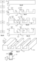
- FIG. 1A describes the main stages of manufacturing a structural element 1 of panel type, comprising a skin 11 from which stiffeners 12 project, this structural element being schematized on the figure 1F .
- the term structural element designates an element intended for mechanical construction, whose mechanical characteristics are important to guarantee the integrity of the structure of said construction.
- Dissolving is a thermomechanical treatment known to those skilled in the art. This treatment amounts to heating an alloy for a sufficient time to allow dissolution of precipitates present in the alloy so that alloy elements, present in the alloy, are in a solid solution. The solution temperature depends on the alloy. A solution is followed by quenching, during which the alloy is cooled quickly, so as to maintain a homogeneous distribution of the alloy elements. Hardening by precipitation can be obtained during a subsequent stage of natural or artificial aging or tempering. The solution, quenching, stress relieving and tempering conditions are determined by those skilled in the art depending on the alloy and the dimensions of the part.
- thermomechanical treatment can be carried out in successive or separate stages.
- solution and quenching steps are carried out during step 110 while the tempering is carried out at a later stage of the process, as described below.
- the process may involve neither deformation, nor thermomechanical treatment, nor adjustment of dimensions, in which case the working part 10' corresponds to the base part 10.
- Step 120 machining.
- the work piece is the subject of machining, the term machining designating a removal of material so as to constitute a predetermined shape. It is in particular a process of the turning, milling, boring, electroerosion, grinding, or polishing type.
- the machining is carried out so as to form a skin 11 extending, along the transverse axis Z, between an external surface 11e and an internal surface 11i.
- the thickness of the skin is preferably less than 4 cm, 2 cm, or even 1.5 cm or 1 cm. Machining also makes it possible to form at least one stiffener blank 12', extending, along the transverse axis Z, between the internal surface 11i and an end called the distal end 12'd.
- the distal end 12'd of the stiffener blank 12' extends at a distance d 1 , called the first extension distance, from the internal surface 11i.
- the first extension distance d 1 can for example be between 1 cm and 5 cm, or between 1 cm and 10 cm.
- the stiffener blank 12' extends in a direction of extension corresponding to the transverse axis Z, the latter being perpendicular to the internal surface 11i. Another direction of extension, secant of the internal surface 11i, is possible.
- several stiffener blanks 12' are simultaneously formed during this step.
- thermomechanical treatments are not carried out following step 120, that is to say after machining, but nevertheless have the advantage of being carried out on a part thin base.
- it is not necessary to carry out a stress relief step on a machined product of complex shape, as described in WO2004/056501 , which can prove difficult industrially.
- Step 130 ( fig. 1D ): addition of material.
- This step aims to extend the stiffener blank 12', in the direction of extension, so as to move the distal end 12'd away from the internal surface 11i.
- a stiffener 12 the distal end 12d of which extends at a distance d 2 from the internal surface 11i, called the second extension distance, greater than the first extension distance d 1 .
- the second extension distance d 2 can be greater than 1.5 times, or even 2 times, the first extension distance d 1 , or even more.
- Step 130 can lead to increasing the extension distance by more than 10 mm, or even more than 30 mm.
- each stiffener 12 formed extends between a proximal end 12p, in contact with the internal surface 11i, and the distal end 12d formed by the addition of material.
- additive manufacturing is defined according to the French standard XP E67-001: “set of processes allowing the manufacture, layer by layer, by adding material, of a physical object from a digital object”.
- ASTM F2792-10 also defines additive manufacturing.
- Different additive manufacturing methods are also defined and described in the ISO/ASTM 17296-1 standard.
- the use of additive manufacturing to produce an aluminum part, with low porosity, was described in the document WO2015006447 .
- the application of successive layers, called elementary layers, can be carried out by application of a so-called filler material on the end 12d, then melting or sintering of the filler material using an energy source.
- the filler material can be in the form of a powder or a wire, or even a rod or a strip.
- WAAM additive manufacturing method
- Other methods that can be used include, for example, and without limitation, the melting or sintering of a filler material taking the form of a powder. This can be laser fusion or sintering.
- the Swedish company Arcam has developed a beam fusion-type additive manufacturing process of electrons dedicated to the production of aeronautical components, for example turbine blades.
- Another known method of additive manufacturing is additive manufacturing by friction stir, usually referred to by the Anglo-Saxon term “friction stir additive manufacturing”. This method is for example described in Puleo, Shawn Michael, "Additive Friction Stir Manufacturing of 7055 Aluminum Alloy” (2016). Senior Honors Theses. Paper 75 , or in the document US2014/0134325 .
- each added elementary layer is typically at least of the order of 10 microns and can also reach a few millimeters, for example 5 mm.
- the different elementary layers can be made up of the same material. According to a variant, the elementary layers are not made of the same material, the material constituting an elementary layer being able to vary from one elementary layer to another. Each elementary layer can be of the same thickness. According to a variant, elementary layers can be of different thicknesses.
- Step 130 may also include a thermomechanical treatment following the addition of material. It may for example be a deformation by compression, for example hot isostatic compression. This makes it possible to fill pores formed during the addition of material.
- Step 140 ( fig. 1E ) : Finishing.
- This step may include so-called finishing machining of the part obtained following step 130, so as to obtain a surface condition compatible with the intended end use.
- step 140 may include a tempering step before or, preferably, after finishing machining.
- the method does not require the use of a very thick base part 10, compared to the methods of the prior art according to which the skin 11 and the stiffeners 12 are machined in the mass from the same base part.
- the base part must have a thickness, along the transverse axis Z, greater than or equal to the thickness of the skin 11 added to the thickness of the stiffener blank 12', i.e. say the thickness of the skin 11 and the first extension distance d 1 . This allows an improvement in the buy to fly ratio previously mentioned.
- the thickness of the base part 10 can be reduced by a factor greater than or equal to 2. For example, to manufacture a panel whose total thickness is 70 mm, using a mass machining process.
- a base part is used whose thickness is approximately 75 mm.
- the thickness of the base part can be reduced to 30 mm, instead of 75 mm, i.e. a gain in thickness of 45 mm.
- the total thickness of 70 mm corresponds to the thickness ⁇ of the skin 11 added to the height of the stiffeners, that is to say the second extension distance d 2 described above.
- thermomechanical treatment is linked to the influence of the thermomechanical treatment on the mechanical properties.
- the thermomechanical treatment whether applied during step 110 or following step 120, or during step 140, is carried out on a work piece whose thickness is reduced compared to the prior art.
- the effectiveness of thermomechanical treatments is limited by the thickness of the treated part, to the extent that lower quenching speeds are obtained on thicker parts.
- Applying a thermomechanical treatment to a thinner part helps obtain more advantageous mechanical properties. These mechanical properties are also more predictable, because they are less subject to fluctuations linked to thermal diffusion. In addition, this reduces the duration of the thermomechanical treatment, which increases the efficiency of the process and reduces the costs incurred.
- the mechanical properties are thus controlled, in particular at the level of the most critical parts of the part, corresponding to the skin 10 or to the interface between the skin 10 and the stiffeners 12 (that is to say at the level of the the proximal end 12p of the stiffeners), on which the mechanical stresses can be significant. If the deposition of material was carried out directly on the skin, the junction between the skin and the added stiffener would be located at a critical part with regard to fatigue life in particular.
- Another consequence of reducing the thickness of the base part is that the latter is easier to shape, as illustrated in a variant of the first embodiment, described below, in connection with the Figures 2A to 2F .
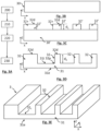
- the objective is to obtain a structural element 2 whose skin is not flat, but takes a curved shape, for example by being curved, as shown schematically on the Figure 2F .
- Such a shape can be adapted to a fuselage, a door frame or a wing element.
- Steps 100 to 150 of this variant are respectively similar to steps 100 to 150 previously described.
- the process includes, during step 110, a deformation of the base part, so that it conforms to the predefined curved shape.
- the force to be applied to deform a 30 mm thick part can be significantly less than that necessary to obtain a similar deformation of a part with a thickness of 75 mm.
- the gain obtained can be greater than 5 or 6, that is to say that the force exerted to obtain the deformation is at least 5 or 6 times lower.
- the process can be subject to machining, called finishing, so as to improve the surface condition of the part obtained. It can also be tempered before or after finishing machining.
- the process can be subject to machining, called finishing, so as to improve the surface condition of the part obtained. It can also be tempered before or after finishing machining.
- the invention can be implemented to produce structural elements of buildings or vehicles, intended for land, maritime or air transport, and in particular in the manufacture of structural elements for fuselages or aircraft wings. . It is in particular intended to be used to produce structural elements in aluminum or aluminum alloy, from an aluminum base part, the additional material added during the addition step also being aluminum or an aluminum alloy.
Landscapes
- Engineering & Computer Science (AREA)
- Chemical & Material Sciences (AREA)
- Manufacturing & Machinery (AREA)
- Materials Engineering (AREA)
- Mechanical Engineering (AREA)
- Composite Materials (AREA)
- Physics & Mathematics (AREA)
- Optics & Photonics (AREA)
- Plasma & Fusion (AREA)
- Powder Metallurgy (AREA)
- Heat Treatment Of Articles (AREA)
- Forging (AREA)
Claims (11)
- Verfahren zum Herstellen eines Strukturelements (3, 4) aus einem sogenannten metallischen Grundwerkstück (30, 40), wobei das Strukturelement eine Haut (31, 41) und mindestens eine Versteifung (32, 42) beinhaltet, wobei sich die Versteifung aus der Haut bis zu einem distalen Ende (32d, 42d) erstreckt, wobei das Verfahren die folgenden Schritte beinhaltet:a) Erhalten eines Arbeitswerkstücks (30', 40') aus dem Grundwerkstück (30, 40), wobei das Grundwerkstück ein Blech ist, welches durch Gießen und danach Walzen erhalten wird;b) Hinzufügen von Material (32+, 42+) auf das Arbeitswerkstück, um mindestens ein Versteifungsvormaterial (32', 42') zu bilden, das sich aus dem Arbeitswerkstück bis zu einem distalen Ende (32d, 42d) in einer Erstreckungsrichtung erstreckt, die das Arbeitswerkstück schneidet, wobei das distale Ende in einem Abstand (d1), erster Erstreckungsabstand genannt, von dem Arbeitswerkstück angeordnet ist, wobei das Hinzufügen von Material durch additive Fertigung durch nacheinander Beigeben der elementaren Materialschichten durchgeführt wird;c) Bearbeiten des Arbeitswerkstücks (30', 40') zum Ausdünnen des Arbeitswerkstücks um das in Schritt b) gebildete Versteifungsvormaterial herum, wobei das so ausgedünnte Arbeitswerkstück eine Haut (31, 41) bildet, die sich zwischen einer Innenoberfläche (31i, 41i) und einer Außenoberfläche (31e, 41e) erstreckt, wobei die Bearbeitung bewirkt, das Versteifungsvormaterial (32', 42') bis zur Innenoberfläche zu verlängern, um eine Versteifung (32, 42) zu erhalten, deren distales Ende (32d, 42d) sich gemäß einem zweiten Erstreckungsabstand (d2)von der Innenoberfläche erstreckt, wobei der zweite Erstreckungsabstand (d2) 1,5 mal größer als der erste Erstreckungsabstand (d1) ist.
- Verfahren zum Herstellen nach Anspruch 1, wobei das Arbeitswerkstück (30', 40') dem Grundwerkstück entspricht.
- Verfahren zum Herstellen nach Anspruch 1, wobei der Schritt a) beinhaltet:- das Anwenden einer thermomechanischen Behandlung auf das Grundwerkstück (30, 40) oder auf das Arbeitswerkstück (30', 40');- und/oder eine Formgebung des Grundwerkstücks (30, 40).
- Verfahren zum Herstellen nach Anspruch 3, wobei die Formgebung eine Verformung beinhaltet, um ein Arbeitswerkstück (, 40') in geschwungener Form zu erhalten.
- Verfahren zum Herstellen nach Anspruch 4, wobei die thermomechanische Behandlung ein Lösungsglühen, gefolgt von einem Abschrecken beinhaltet.
- Verfahren zum Herstellen nach einem der vorstehenden Ansprüche, welches nach dem Schritt c) ein Vergüten beinhaltet.
- Verfahren zum Herstellen nach einem der vorstehenden Ansprüche, welches nach dem Schritt c) einen sogenannten Fertigbearbeitungsschritt beinhaltet.
- Verfahren zum Herstellen nach einem der vorstehenden Ansprüche, wobei jede Werkstoffschicht nacheinander mit einer Dicke hinzugefügt wird, die zwischen 10 µm und 5 mm liegt.
- Verfahren zum Herstellen nach einem der vorstehenden Ansprüche, wobei das Grundwerkstück (30, 40) aus einer Legierung auf Basis von Aluminium oder Titan oder Magnesium ist, und wobei beim Schritt des Hinzufügens von Material das hinzugefügte Material (32+, 42+) eine Legierung aus Aluminium oder aus Titan oder aus Magnesium ist.
- Strukturelement, das für eine Struktur einer Konstruktion bestimmt ist, dadurch gekennzeichnet, dass es durch Umsetzen des Verfahrens nach einem der vorstehenden Ansprüche hergestellt wird.
- Fahrzeug, dessen Metallstruktur mindestens ein Strukturelement (3, 4) beinhaltet, das gemäß dem Verfahren nach einem der Ansprüche 1 bis 9 hergestellt wird, wobei das Fahrzeug für den Land-, See-, oder Luft- oder Weltraumtransport bestimmt ist.
Applications Claiming Priority (2)
| Application Number | Priority Date | Filing Date | Title |
|---|---|---|---|
| FR1662068A FR3059578B1 (fr) | 2016-12-07 | 2016-12-07 | Procede de fabrication d'un element de structure |
| PCT/FR2017/053445 WO2018104673A1 (fr) | 2016-12-07 | 2017-12-07 | Procédé de fabrication hybride d'un élément de structure avec raidisseur(s) |
Publications (2)
| Publication Number | Publication Date |
|---|---|
| EP3551364A1 EP3551364A1 (de) | 2019-10-16 |
| EP3551364B1 true EP3551364B1 (de) | 2024-05-15 |
Family
ID=58054283
Family Applications (1)
| Application Number | Title | Priority Date | Filing Date |
|---|---|---|---|
| EP17822386.3A Active EP3551364B1 (de) | 2016-12-07 | 2017-12-07 | Hybrider herstellungsprozess von stukturelement mit versteifung(en) |
Country Status (5)
| Country | Link |
|---|---|
| US (1) | US20200078862A1 (de) |
| EP (1) | EP3551364B1 (de) |
| CA (1) | CA3041640A1 (de) |
| FR (1) | FR3059578B1 (de) |
| WO (1) | WO2018104673A1 (de) |
Families Citing this family (6)
| Publication number | Priority date | Publication date | Assignee | Title |
|---|---|---|---|---|
| TWI682822B (zh) * | 2018-07-16 | 2020-01-21 | 國立中正大學 | 摩擦攪拌積層製造方法 |
| DE102018212156A1 (de) * | 2018-07-20 | 2020-01-23 | Technische Universität Ilmenau | Verfahren zum Beschichten eines Werkstücks, Werkstück, Beschichtungsmaschine, und Verwendung eines Reibschweißgeräts |
| WO2020038930A1 (de) | 2018-08-21 | 2020-02-27 | Sascha Larch | Verfahren zur herstellung eines leichtbau-drucktanks und leichtbau-drucktank |
| US11491718B2 (en) * | 2019-12-20 | 2022-11-08 | Nutech Ventures | Hybrid additive manufacturing method |
| CN115446610B (zh) * | 2022-07-21 | 2023-07-21 | 成都飞机工业(集团)有限责任公司 | 一种冷压消除残余应力的方法 |
| CN116021234B (zh) * | 2022-11-15 | 2025-08-22 | 成都航新航空装备科技有限公司 | 一种框段零件加工方法 |
Family Cites Families (11)
| Publication number | Priority date | Publication date | Assignee | Title |
|---|---|---|---|---|
| FR1458451A (fr) | 1965-09-14 | 1966-03-04 | Compteurs Comp D | Dispositif d'épuration humide |
| BR0317336B1 (pt) | 2002-12-17 | 2013-07-09 | processo de fabricaÇço de elementos de estrutura por usinagem de chapas espessas e peÇa metÁlica usinada | |
| US20080041921A1 (en) | 2005-09-26 | 2008-02-21 | Kevin Creehan | Friction stir fabrication |
| GB2493537A (en) * | 2011-08-10 | 2013-02-13 | Bae Systems Plc | Forming a layered structure |
| FR2983424B1 (fr) * | 2011-12-02 | 2014-09-19 | Nantes Ecole Centrale | Procede et dispositif d'usinage par addition de matiere et mise en forme combinees |
| FR3004196B1 (fr) * | 2013-04-03 | 2016-05-06 | Constellium France | Toles en alliage d'aluminium-cuivre-lithium pour la fabrication de fuselages d'avion. |
| EP2801512B1 (de) * | 2013-05-07 | 2020-10-07 | EDAG Engineering GmbH | Verbundstruktur mit generativ gefertigter Funktionsstruktur |
| CN108500184A (zh) | 2013-07-10 | 2018-09-07 | 奥科宁克有限公司 | 用于制作锻造产品和其他加工产品的方法 |
| CN106660174B (zh) * | 2014-07-03 | 2019-06-04 | 自动工程公司 | 加强结构部件 |
| FR3025491A1 (fr) * | 2014-09-09 | 2016-03-11 | Assystem France | Panneau raidi pour aeronef. |
| DE102014116938A1 (de) | 2014-11-19 | 2016-05-19 | Airbus Operations Gmbh | Herstellung von Komponenten eines Fahrzeugs unter Anwendung von Additive Layer Manufacturing |
-
2016
- 2016-12-07 FR FR1662068A patent/FR3059578B1/fr active Active
-
2017
- 2017-12-07 CA CA3041640A patent/CA3041640A1/fr active Pending
- 2017-12-07 EP EP17822386.3A patent/EP3551364B1/de active Active
- 2017-12-07 US US16/466,653 patent/US20200078862A1/en not_active Abandoned
- 2017-12-07 WO PCT/FR2017/053445 patent/WO2018104673A1/fr not_active Ceased
Also Published As
| Publication number | Publication date |
|---|---|
| US20200078862A1 (en) | 2020-03-12 |
| FR3059578A1 (fr) | 2018-06-08 |
| CA3041640A1 (fr) | 2018-06-14 |
| WO2018104673A1 (fr) | 2018-06-14 |
| EP3551364A1 (de) | 2019-10-16 |
| FR3059578B1 (fr) | 2019-06-28 |
Similar Documents
| Publication | Publication Date | Title |
|---|---|---|
| EP3551364B1 (de) | Hybrider herstellungsprozess von stukturelement mit versteifung(en) | |
| CA2823525C (fr) | Procede de realisation d'un renfort metallique | |
| EP3282090B1 (de) | Schaufelprofilanordnung und verfahren zum zusammenbau | |
| EP1799391B8 (de) | Geschweisstes strukturelement mit mindestens zwei aluminiumlegierungsteilen, die verschiedene metallurgische zustände haben, und verfahren zur herstellung solch eines elements | |
| US9862059B2 (en) | Surfacing of additively manufactured components and corresponding manufactured components of a turbomachine | |
| CA2948252C (en) | Turbine airfoil with passive morphing structure | |
| US20170333995A1 (en) | Method for connecting workpieces which are produced from a raw material using an additive manufacturing process` | |
| US20160222790A1 (en) | Manufacturing method for a dual wall component | |
| FR3046557A1 (fr) | Procede de fabrication d'un bouclier de bord d'attaque comprenant une etape de fabrication additive et bouclier de bord d'attaque | |
| EP2429752A1 (de) | Verfahren zur montage von aluminiumlegierungsteilen mittels schweissen, einschliesslich kaltverformung und anschliessendem tempern des gesamten schweissbereichs | |
| EP3194112B1 (de) | Verfahren zur herstellung einer vorderkantenabschirmung | |
| US8439647B2 (en) | Cooled turbine airfoil fabricated from sheet material | |
| FR3094253A1 (fr) | Procede de collage d’une piece metallique sur un element en materiau composite d’une turbomachine d’aeronef | |
| FR3059648A1 (fr) | Procede de fabrication d'un element d'aeronef et element d'aeronef mettant en oeuvre une impression tridimensionnelle | |
| EP2327501B1 (de) | Verfahren zum Verbinden einer ersten Komponente mit einer zweiten Komponente zum Bilden einer Verbindung | |
| US20180105914A1 (en) | Hybrid component and method of making | |
| FR2991612A1 (fr) | Procede d'obtention par fonderie d'une piece comportant une portion effilee | |
| EP3442741B1 (de) | Kern für hochtemperaturformen eines metallteils und herstellungsverfahren | |
| WO2019040509A1 (en) | MULTI-MATERIAL COMPONENTS AND PROCESSES FOR THEIR MANUFACTURE | |
| EP4251855B1 (de) | Verfahren und vorrichtung zur herstellung einer zweimaterial-scheibe einer turbomaschinenscheibe und mit diesem verfahren hergestellte scheibe | |
| US20180141638A1 (en) | Propeller counterweight | |
| WO2026008947A1 (fr) | Procede de reparation d'un insert d'outillage pour forge par matriçage |
Legal Events
| Date | Code | Title | Description |
|---|---|---|---|
| STAA | Information on the status of an ep patent application or granted ep patent |
Free format text: STATUS: UNKNOWN |
|
| STAA | Information on the status of an ep patent application or granted ep patent |
Free format text: STATUS: THE INTERNATIONAL PUBLICATION HAS BEEN MADE |
|
| PUAI | Public reference made under article 153(3) epc to a published international application that has entered the european phase |
Free format text: ORIGINAL CODE: 0009012 |
|
| STAA | Information on the status of an ep patent application or granted ep patent |
Free format text: STATUS: REQUEST FOR EXAMINATION WAS MADE |
|
| 17P | Request for examination filed |
Effective date: 20190627 |
|
| AK | Designated contracting states |
Kind code of ref document: A1 Designated state(s): AL AT BE BG CH CY CZ DE DK EE ES FI FR GB GR HR HU IE IS IT LI LT LU LV MC MK MT NL NO PL PT RO RS SE SI SK SM TR |
|
| AX | Request for extension of the european patent |
Extension state: BA ME |
|
| DAV | Request for validation of the european patent (deleted) | ||
| DAX | Request for extension of the european patent (deleted) | ||
| STAA | Information on the status of an ep patent application or granted ep patent |
Free format text: STATUS: EXAMINATION IS IN PROGRESS |
|
| 17Q | First examination report despatched |
Effective date: 20211014 |
|
| REG | Reference to a national code |
Ref country code: DE Free format text: PREVIOUS MAIN CLASS: B22F0003105000 Ipc: B22F0010220000 Ref country code: DE Ref legal event code: R079 Ref document number: 602017081972 Country of ref document: DE Free format text: PREVIOUS MAIN CLASS: B22F0003105000 Ipc: B22F0010220000 |
|
| GRAP | Despatch of communication of intention to grant a patent |
Free format text: ORIGINAL CODE: EPIDOSNIGR1 |
|
| STAA | Information on the status of an ep patent application or granted ep patent |
Free format text: STATUS: GRANT OF PATENT IS INTENDED |
|
| RIC1 | Information provided on ipc code assigned before grant |
Ipc: B22F 10/66 20210101ALN20231123BHEP Ipc: B22F 10/28 20210101ALN20231123BHEP Ipc: B22F 10/64 20210101ALN20231123BHEP Ipc: B23K 26/34 20140101ALI20231123BHEP Ipc: B22F 7/08 20060101ALI20231123BHEP Ipc: B22F 7/04 20060101ALI20231123BHEP Ipc: B22F 10/25 20210101ALI20231123BHEP Ipc: B22F 10/22 20210101AFI20231123BHEP |
|
| RIC1 | Information provided on ipc code assigned before grant |
Ipc: B22F 10/66 20210101ALN20231128BHEP Ipc: B22F 10/28 20210101ALN20231128BHEP Ipc: B22F 10/64 20210101ALN20231128BHEP Ipc: B23K 26/34 20140101ALI20231128BHEP Ipc: B22F 7/08 20060101ALI20231128BHEP Ipc: B22F 7/04 20060101ALI20231128BHEP Ipc: B22F 10/25 20210101ALI20231128BHEP Ipc: B22F 10/22 20210101AFI20231128BHEP |
|
| INTG | Intention to grant announced |
Effective date: 20231218 |
|
| GRAS | Grant fee paid |
Free format text: ORIGINAL CODE: EPIDOSNIGR3 |
|
| GRAA | (expected) grant |
Free format text: ORIGINAL CODE: 0009210 |
|
| STAA | Information on the status of an ep patent application or granted ep patent |
Free format text: STATUS: THE PATENT HAS BEEN GRANTED |
|
| AK | Designated contracting states |
Kind code of ref document: B1 Designated state(s): AL AT BE BG CH CY CZ DE DK EE ES FI FR GB GR HR HU IE IS IT LI LT LU LV MC MK MT NL NO PL PT RO RS SE SI SK SM TR |
|
| REG | Reference to a national code |
Ref country code: CH Ref legal event code: EP Ref country code: GB Ref legal event code: FG4D Free format text: NOT ENGLISH |
|
| P01 | Opt-out of the competence of the unified patent court (upc) registered |
Effective date: 20240422 |
|
| REG | Reference to a national code |
Ref country code: DE Ref legal event code: R096 Ref document number: 602017081972 Country of ref document: DE |
|
| REG | Reference to a national code |
Ref country code: IE Ref legal event code: FG4D Free format text: LANGUAGE OF EP DOCUMENT: FRENCH |
|
| REG | Reference to a national code |
Ref country code: LT Ref legal event code: MG9D |
|
| REG | Reference to a national code |
Ref country code: NL Ref legal event code: MP Effective date: 20240515 |
|
| PG25 | Lapsed in a contracting state [announced via postgrant information from national office to epo] |
Ref country code: IS Free format text: LAPSE BECAUSE OF FAILURE TO SUBMIT A TRANSLATION OF THE DESCRIPTION OR TO PAY THE FEE WITHIN THE PRESCRIBED TIME-LIMIT Effective date: 20240915 |
|
| PG25 | Lapsed in a contracting state [announced via postgrant information from national office to epo] |
Ref country code: BG Free format text: LAPSE BECAUSE OF FAILURE TO SUBMIT A TRANSLATION OF THE DESCRIPTION OR TO PAY THE FEE WITHIN THE PRESCRIBED TIME-LIMIT Effective date: 20240515 |
|
| PG25 | Lapsed in a contracting state [announced via postgrant information from national office to epo] |
Ref country code: FI Free format text: LAPSE BECAUSE OF FAILURE TO SUBMIT A TRANSLATION OF THE DESCRIPTION OR TO PAY THE FEE WITHIN THE PRESCRIBED TIME-LIMIT Effective date: 20240515 Ref country code: HR Free format text: LAPSE BECAUSE OF FAILURE TO SUBMIT A TRANSLATION OF THE DESCRIPTION OR TO PAY THE FEE WITHIN THE PRESCRIBED TIME-LIMIT Effective date: 20240515 |
|
| PG25 | Lapsed in a contracting state [announced via postgrant information from national office to epo] |
Ref country code: GR Free format text: LAPSE BECAUSE OF FAILURE TO SUBMIT A TRANSLATION OF THE DESCRIPTION OR TO PAY THE FEE WITHIN THE PRESCRIBED TIME-LIMIT Effective date: 20240816 |
|
| PG25 | Lapsed in a contracting state [announced via postgrant information from national office to epo] |
Ref country code: PT Free format text: LAPSE BECAUSE OF FAILURE TO SUBMIT A TRANSLATION OF THE DESCRIPTION OR TO PAY THE FEE WITHIN THE PRESCRIBED TIME-LIMIT Effective date: 20240916 |
|
| REG | Reference to a national code |
Ref country code: AT Ref legal event code: MK05 Ref document number: 1686553 Country of ref document: AT Kind code of ref document: T Effective date: 20240515 |
|
| PG25 | Lapsed in a contracting state [announced via postgrant information from national office to epo] |
Ref country code: NL Free format text: LAPSE BECAUSE OF FAILURE TO SUBMIT A TRANSLATION OF THE DESCRIPTION OR TO PAY THE FEE WITHIN THE PRESCRIBED TIME-LIMIT Effective date: 20240515 |
|
| PG25 | Lapsed in a contracting state [announced via postgrant information from national office to epo] |
Ref country code: ES Free format text: LAPSE BECAUSE OF FAILURE TO SUBMIT A TRANSLATION OF THE DESCRIPTION OR TO PAY THE FEE WITHIN THE PRESCRIBED TIME-LIMIT Effective date: 20240515 |
|
| PG25 | Lapsed in a contracting state [announced via postgrant information from national office to epo] |
Ref country code: AT Free format text: LAPSE BECAUSE OF FAILURE TO SUBMIT A TRANSLATION OF THE DESCRIPTION OR TO PAY THE FEE WITHIN THE PRESCRIBED TIME-LIMIT Effective date: 20240515 |
|
| PG25 | Lapsed in a contracting state [announced via postgrant information from national office to epo] |
Ref country code: PL Free format text: LAPSE BECAUSE OF FAILURE TO SUBMIT A TRANSLATION OF THE DESCRIPTION OR TO PAY THE FEE WITHIN THE PRESCRIBED TIME-LIMIT Effective date: 20240515 |
|
| PG25 | Lapsed in a contracting state [announced via postgrant information from national office to epo] |
Ref country code: LV Free format text: LAPSE BECAUSE OF FAILURE TO SUBMIT A TRANSLATION OF THE DESCRIPTION OR TO PAY THE FEE WITHIN THE PRESCRIBED TIME-LIMIT Effective date: 20240515 |
|
| PG25 | Lapsed in a contracting state [announced via postgrant information from national office to epo] |
Ref country code: PT Free format text: LAPSE BECAUSE OF FAILURE TO SUBMIT A TRANSLATION OF THE DESCRIPTION OR TO PAY THE FEE WITHIN THE PRESCRIBED TIME-LIMIT Effective date: 20240916 Ref country code: PL Free format text: LAPSE BECAUSE OF FAILURE TO SUBMIT A TRANSLATION OF THE DESCRIPTION OR TO PAY THE FEE WITHIN THE PRESCRIBED TIME-LIMIT Effective date: 20240515 Ref country code: NO Free format text: LAPSE BECAUSE OF FAILURE TO SUBMIT A TRANSLATION OF THE DESCRIPTION OR TO PAY THE FEE WITHIN THE PRESCRIBED TIME-LIMIT Effective date: 20240815 Ref country code: NL Free format text: LAPSE BECAUSE OF FAILURE TO SUBMIT A TRANSLATION OF THE DESCRIPTION OR TO PAY THE FEE WITHIN THE PRESCRIBED TIME-LIMIT Effective date: 20240515 Ref country code: LV Free format text: LAPSE BECAUSE OF FAILURE TO SUBMIT A TRANSLATION OF THE DESCRIPTION OR TO PAY THE FEE WITHIN THE PRESCRIBED TIME-LIMIT Effective date: 20240515 Ref country code: IS Free format text: LAPSE BECAUSE OF FAILURE TO SUBMIT A TRANSLATION OF THE DESCRIPTION OR TO PAY THE FEE WITHIN THE PRESCRIBED TIME-LIMIT Effective date: 20240915 Ref country code: HR Free format text: LAPSE BECAUSE OF FAILURE TO SUBMIT A TRANSLATION OF THE DESCRIPTION OR TO PAY THE FEE WITHIN THE PRESCRIBED TIME-LIMIT Effective date: 20240515 Ref country code: GR Free format text: LAPSE BECAUSE OF FAILURE TO SUBMIT A TRANSLATION OF THE DESCRIPTION OR TO PAY THE FEE WITHIN THE PRESCRIBED TIME-LIMIT Effective date: 20240816 Ref country code: FI Free format text: LAPSE BECAUSE OF FAILURE TO SUBMIT A TRANSLATION OF THE DESCRIPTION OR TO PAY THE FEE WITHIN THE PRESCRIBED TIME-LIMIT Effective date: 20240515 Ref country code: ES Free format text: LAPSE BECAUSE OF FAILURE TO SUBMIT A TRANSLATION OF THE DESCRIPTION OR TO PAY THE FEE WITHIN THE PRESCRIBED TIME-LIMIT Effective date: 20240515 Ref country code: BG Free format text: LAPSE BECAUSE OF FAILURE TO SUBMIT A TRANSLATION OF THE DESCRIPTION OR TO PAY THE FEE WITHIN THE PRESCRIBED TIME-LIMIT Effective date: 20240515 Ref country code: AT Free format text: LAPSE BECAUSE OF FAILURE TO SUBMIT A TRANSLATION OF THE DESCRIPTION OR TO PAY THE FEE WITHIN THE PRESCRIBED TIME-LIMIT Effective date: 20240515 Ref country code: RS Free format text: LAPSE BECAUSE OF FAILURE TO SUBMIT A TRANSLATION OF THE DESCRIPTION OR TO PAY THE FEE WITHIN THE PRESCRIBED TIME-LIMIT Effective date: 20240815 |
|
| PG25 | Lapsed in a contracting state [announced via postgrant information from national office to epo] |
Ref country code: DK Free format text: LAPSE BECAUSE OF FAILURE TO SUBMIT A TRANSLATION OF THE DESCRIPTION OR TO PAY THE FEE WITHIN THE PRESCRIBED TIME-LIMIT Effective date: 20240515 |
|
| PG25 | Lapsed in a contracting state [announced via postgrant information from national office to epo] |
Ref country code: EE Free format text: LAPSE BECAUSE OF FAILURE TO SUBMIT A TRANSLATION OF THE DESCRIPTION OR TO PAY THE FEE WITHIN THE PRESCRIBED TIME-LIMIT Effective date: 20240515 |
|
| PG25 | Lapsed in a contracting state [announced via postgrant information from national office to epo] |
Ref country code: CZ Free format text: LAPSE BECAUSE OF FAILURE TO SUBMIT A TRANSLATION OF THE DESCRIPTION OR TO PAY THE FEE WITHIN THE PRESCRIBED TIME-LIMIT Effective date: 20240515 |
|
| PG25 | Lapsed in a contracting state [announced via postgrant information from national office to epo] |
Ref country code: SK Free format text: LAPSE BECAUSE OF FAILURE TO SUBMIT A TRANSLATION OF THE DESCRIPTION OR TO PAY THE FEE WITHIN THE PRESCRIBED TIME-LIMIT Effective date: 20240515 Ref country code: RO Free format text: LAPSE BECAUSE OF FAILURE TO SUBMIT A TRANSLATION OF THE DESCRIPTION OR TO PAY THE FEE WITHIN THE PRESCRIBED TIME-LIMIT Effective date: 20240515 |
|
| PG25 | Lapsed in a contracting state [announced via postgrant information from national office to epo] |
Ref country code: SM Free format text: LAPSE BECAUSE OF FAILURE TO SUBMIT A TRANSLATION OF THE DESCRIPTION OR TO PAY THE FEE WITHIN THE PRESCRIBED TIME-LIMIT Effective date: 20240515 |
|
| PG25 | Lapsed in a contracting state [announced via postgrant information from national office to epo] |
Ref country code: SM Free format text: LAPSE BECAUSE OF FAILURE TO SUBMIT A TRANSLATION OF THE DESCRIPTION OR TO PAY THE FEE WITHIN THE PRESCRIBED TIME-LIMIT Effective date: 20240515 Ref country code: SK Free format text: LAPSE BECAUSE OF FAILURE TO SUBMIT A TRANSLATION OF THE DESCRIPTION OR TO PAY THE FEE WITHIN THE PRESCRIBED TIME-LIMIT Effective date: 20240515 Ref country code: RO Free format text: LAPSE BECAUSE OF FAILURE TO SUBMIT A TRANSLATION OF THE DESCRIPTION OR TO PAY THE FEE WITHIN THE PRESCRIBED TIME-LIMIT Effective date: 20240515 Ref country code: EE Free format text: LAPSE BECAUSE OF FAILURE TO SUBMIT A TRANSLATION OF THE DESCRIPTION OR TO PAY THE FEE WITHIN THE PRESCRIBED TIME-LIMIT Effective date: 20240515 Ref country code: DK Free format text: LAPSE BECAUSE OF FAILURE TO SUBMIT A TRANSLATION OF THE DESCRIPTION OR TO PAY THE FEE WITHIN THE PRESCRIBED TIME-LIMIT Effective date: 20240515 Ref country code: CZ Free format text: LAPSE BECAUSE OF FAILURE TO SUBMIT A TRANSLATION OF THE DESCRIPTION OR TO PAY THE FEE WITHIN THE PRESCRIBED TIME-LIMIT Effective date: 20240515 |
|
| PG25 | Lapsed in a contracting state [announced via postgrant information from national office to epo] |
Ref country code: IT Free format text: LAPSE BECAUSE OF FAILURE TO SUBMIT A TRANSLATION OF THE DESCRIPTION OR TO PAY THE FEE WITHIN THE PRESCRIBED TIME-LIMIT Effective date: 20240515 |
|
| REG | Reference to a national code |
Ref country code: DE Ref legal event code: R097 Ref document number: 602017081972 Country of ref document: DE |
|
| PLBE | No opposition filed within time limit |
Free format text: ORIGINAL CODE: 0009261 |
|
| STAA | Information on the status of an ep patent application or granted ep patent |
Free format text: STATUS: NO OPPOSITION FILED WITHIN TIME LIMIT |
|
| 26N | No opposition filed |
Effective date: 20250218 |
|
| PG25 | Lapsed in a contracting state [announced via postgrant information from national office to epo] |
Ref country code: SI Free format text: LAPSE BECAUSE OF FAILURE TO SUBMIT A TRANSLATION OF THE DESCRIPTION OR TO PAY THE FEE WITHIN THE PRESCRIBED TIME-LIMIT Effective date: 20240515 |
|
| PG25 | Lapsed in a contracting state [announced via postgrant information from national office to epo] |
Ref country code: MC Free format text: LAPSE BECAUSE OF FAILURE TO SUBMIT A TRANSLATION OF THE DESCRIPTION OR TO PAY THE FEE WITHIN THE PRESCRIBED TIME-LIMIT Effective date: 20240515 |
|
| REG | Reference to a national code |
Ref country code: CH Ref legal event code: PL |
|
| PG25 | Lapsed in a contracting state [announced via postgrant information from national office to epo] |
Ref country code: LU Free format text: LAPSE BECAUSE OF NON-PAYMENT OF DUE FEES Effective date: 20241207 |
|
| PG25 | Lapsed in a contracting state [announced via postgrant information from national office to epo] |
Ref country code: SE Free format text: LAPSE BECAUSE OF FAILURE TO SUBMIT A TRANSLATION OF THE DESCRIPTION OR TO PAY THE FEE WITHIN THE PRESCRIBED TIME-LIMIT Effective date: 20240515 |
|
| REG | Reference to a national code |
Ref country code: BE Ref legal event code: MM Effective date: 20241231 |
|
| PG25 | Lapsed in a contracting state [announced via postgrant information from national office to epo] |
Ref country code: BE Free format text: LAPSE BECAUSE OF NON-PAYMENT OF DUE FEES Effective date: 20241231 |
|
| PG25 | Lapsed in a contracting state [announced via postgrant information from national office to epo] |
Ref country code: CH Free format text: LAPSE BECAUSE OF NON-PAYMENT OF DUE FEES Effective date: 20241231 |
|
| PG25 | Lapsed in a contracting state [announced via postgrant information from national office to epo] |
Ref country code: IE Free format text: LAPSE BECAUSE OF NON-PAYMENT OF DUE FEES Effective date: 20241207 |
|
| PGFP | Annual fee paid to national office [announced via postgrant information from national office to epo] |
Ref country code: GB Payment date: 20251229 Year of fee payment: 9 |
|
| PGFP | Annual fee paid to national office [announced via postgrant information from national office to epo] |
Ref country code: FR Payment date: 20251226 Year of fee payment: 9 |
|
| PG25 | Lapsed in a contracting state [announced via postgrant information from national office to epo] |
Ref country code: CY Free format text: LAPSE BECAUSE OF FAILURE TO SUBMIT A TRANSLATION OF THE DESCRIPTION OR TO PAY THE FEE WITHIN THE PRESCRIBED TIME-LIMIT; INVALID AB INITIO Effective date: 20171207 |
|
| PGFP | Annual fee paid to national office [announced via postgrant information from national office to epo] |
Ref country code: DE Payment date: 20251229 Year of fee payment: 9 |