EP3551345B1 - Device for printing a picture onto a floor surface - Google Patents
Device for printing a picture onto a floor surface Download PDFInfo
- Publication number
- EP3551345B1 EP3551345B1 EP17822540.5A EP17822540A EP3551345B1 EP 3551345 B1 EP3551345 B1 EP 3551345B1 EP 17822540 A EP17822540 A EP 17822540A EP 3551345 B1 EP3551345 B1 EP 3551345B1
- Authority
- EP
- European Patent Office
- Prior art keywords
- nozzle
- colorant
- image
- robot
- controller
- Prior art date
- Legal status (The legal status is an assumption and is not a legal conclusion. Google has not performed a legal analysis and makes no representation as to the accuracy of the status listed.)
- Active
Links
Images


Classifications
-
- B—PERFORMING OPERATIONS; TRANSPORTING
- B05—SPRAYING OR ATOMISING IN GENERAL; APPLYING FLUENT MATERIALS TO SURFACES, IN GENERAL
- B05B—SPRAYING APPARATUS; ATOMISING APPARATUS; NOZZLES
- B05B13/00—Machines or plants for applying liquids or other fluent materials to surfaces of objects or other work by spraying, not covered by groups B05B1/00 - B05B11/00
- B05B13/005—Machines or plants for applying liquids or other fluent materials to surfaces of objects or other work by spraying, not covered by groups B05B1/00 - B05B11/00 mounted on vehicles or designed to apply a liquid on a very large surface, e.g. on the road, on the surface of large containers
-
- B—PERFORMING OPERATIONS; TRANSPORTING
- B05—SPRAYING OR ATOMISING IN GENERAL; APPLYING FLUENT MATERIALS TO SURFACES, IN GENERAL
- B05B—SPRAYING APPARATUS; ATOMISING APPARATUS; NOZZLES
- B05B12/00—Arrangements for controlling delivery; Arrangements for controlling the spray area
- B05B12/02—Arrangements for controlling delivery; Arrangements for controlling the spray area for controlling time, or sequence, of delivery
- B05B12/04—Arrangements for controlling delivery; Arrangements for controlling the spray area for controlling time, or sequence, of delivery for sequential operation or multiple outlets
-
- B—PERFORMING OPERATIONS; TRANSPORTING
- B05—SPRAYING OR ATOMISING IN GENERAL; APPLYING FLUENT MATERIALS TO SURFACES, IN GENERAL
- B05B—SPRAYING APPARATUS; ATOMISING APPARATUS; NOZZLES
- B05B12/00—Arrangements for controlling delivery; Arrangements for controlling the spray area
- B05B12/08—Arrangements for controlling delivery; Arrangements for controlling the spray area responsive to condition of liquid or other fluent material to be discharged, of ambient medium or of target ; responsive to condition of spray devices or of supply means, e.g. pipes, pumps or their drive means
- B05B12/084—Arrangements for controlling delivery; Arrangements for controlling the spray area responsive to condition of liquid or other fluent material to be discharged, of ambient medium or of target ; responsive to condition of spray devices or of supply means, e.g. pipes, pumps or their drive means responsive to condition of liquid or other fluent material already sprayed on the target, e.g. coating thickness, weight or pattern
-
- B—PERFORMING OPERATIONS; TRANSPORTING
- B05—SPRAYING OR ATOMISING IN GENERAL; APPLYING FLUENT MATERIALS TO SURFACES, IN GENERAL
- B05B—SPRAYING APPARATUS; ATOMISING APPARATUS; NOZZLES
- B05B12/00—Arrangements for controlling delivery; Arrangements for controlling the spray area
- B05B12/08—Arrangements for controlling delivery; Arrangements for controlling the spray area responsive to condition of liquid or other fluent material to be discharged, of ambient medium or of target ; responsive to condition of spray devices or of supply means, e.g. pipes, pumps or their drive means
- B05B12/12—Arrangements for controlling delivery; Arrangements for controlling the spray area responsive to condition of liquid or other fluent material to be discharged, of ambient medium or of target ; responsive to condition of spray devices or of supply means, e.g. pipes, pumps or their drive means responsive to conditions of ambient medium or target, e.g. humidity, temperature position or movement of the target relative to the spray apparatus
-
- B—PERFORMING OPERATIONS; TRANSPORTING
- B05—SPRAYING OR ATOMISING IN GENERAL; APPLYING FLUENT MATERIALS TO SURFACES, IN GENERAL
- B05B—SPRAYING APPARATUS; ATOMISING APPARATUS; NOZZLES
- B05B13/00—Machines or plants for applying liquids or other fluent materials to surfaces of objects or other work by spraying, not covered by groups B05B1/00 - B05B11/00
- B05B13/002—Machines or plants for applying coating liquids or other fluent materials by inkjet
-
- B—PERFORMING OPERATIONS; TRANSPORTING
- B05—SPRAYING OR ATOMISING IN GENERAL; APPLYING FLUENT MATERIALS TO SURFACES, IN GENERAL
- B05B—SPRAYING APPARATUS; ATOMISING APPARATUS; NOZZLES
- B05B13/00—Machines or plants for applying liquids or other fluent materials to surfaces of objects or other work by spraying, not covered by groups B05B1/00 - B05B11/00
- B05B13/02—Means for supporting work; Arrangement or mounting of spray heads; Adaptation or arrangement of means for feeding work
- B05B13/04—Means for supporting work; Arrangement or mounting of spray heads; Adaptation or arrangement of means for feeding work the spray heads being moved during spraying operation
- B05B13/0431—Means for supporting work; Arrangement or mounting of spray heads; Adaptation or arrangement of means for feeding work the spray heads being moved during spraying operation with spray heads moved by robots or articulated arms, e.g. for applying liquid or other fluent material to three-dimensional [3D] surfaces
-
- B—PERFORMING OPERATIONS; TRANSPORTING
- B05—SPRAYING OR ATOMISING IN GENERAL; APPLYING FLUENT MATERIALS TO SURFACES, IN GENERAL
- B05B—SPRAYING APPARATUS; ATOMISING APPARATUS; NOZZLES
- B05B15/00—Details of spraying plant or spraying apparatus not otherwise provided for; Accessories
- B05B15/50—Arrangements for cleaning; Arrangements for preventing deposits, drying-out or blockage; Arrangements for detecting improper discharge caused by the presence of foreign matter
- B05B15/55—Arrangements for cleaning; Arrangements for preventing deposits, drying-out or blockage; Arrangements for detecting improper discharge caused by the presence of foreign matter using cleaning fluids
- B05B15/555—Arrangements for cleaning; Arrangements for preventing deposits, drying-out or blockage; Arrangements for detecting improper discharge caused by the presence of foreign matter using cleaning fluids discharged by cleaning nozzles
-
- B—PERFORMING OPERATIONS; TRANSPORTING
- B41—PRINTING; LINING MACHINES; TYPEWRITERS; STAMPS
- B41J—TYPEWRITERS; SELECTIVE PRINTING MECHANISMS, i.e. MECHANISMS PRINTING OTHERWISE THAN FROM A FORME; CORRECTION OF TYPOGRAPHICAL ERRORS
- B41J2/00—Typewriters or selective printing mechanisms characterised by the printing or marking process for which they are designed
- B41J2/005—Typewriters or selective printing mechanisms characterised by the printing or marking process for which they are designed characterised by bringing liquid or particles selectively into contact with a printing material
- B41J2/01—Ink jet
- B41J2/135—Nozzles
- B41J2/165—Prevention or detection of nozzle clogging, e.g. cleaning, capping or moistening for nozzles
- B41J2/16517—Cleaning of print head nozzles
- B41J2/16552—Cleaning of print head nozzles using cleaning fluids
-
- B—PERFORMING OPERATIONS; TRANSPORTING
- B41—PRINTING; LINING MACHINES; TYPEWRITERS; STAMPS
- B41J—TYPEWRITERS; SELECTIVE PRINTING MECHANISMS, i.e. MECHANISMS PRINTING OTHERWISE THAN FROM A FORME; CORRECTION OF TYPOGRAPHICAL ERRORS
- B41J3/00—Typewriters or selective printing or marking mechanisms characterised by the purpose for which they are constructed
- B41J3/28—Typewriters or selective printing or marking mechanisms characterised by the purpose for which they are constructed for printing downwardly on flat surfaces, e.g. of books, drawings, boxes, envelopes, e.g. flat-bed ink-jet printers
-
- B—PERFORMING OPERATIONS; TRANSPORTING
- B41—PRINTING; LINING MACHINES; TYPEWRITERS; STAMPS
- B41J—TYPEWRITERS; SELECTIVE PRINTING MECHANISMS, i.e. MECHANISMS PRINTING OTHERWISE THAN FROM A FORME; CORRECTION OF TYPOGRAPHICAL ERRORS
- B41J3/00—Typewriters or selective printing or marking mechanisms characterised by the purpose for which they are constructed
- B41J3/407—Typewriters or selective printing or marking mechanisms characterised by the purpose for which they are constructed for marking on special material
-
- G—PHYSICS
- G05—CONTROLLING; REGULATING
- G05D—SYSTEMS FOR CONTROLLING OR REGULATING NON-ELECTRIC VARIABLES
- G05D1/00—Control of position, course, altitude or attitude of land, water, air or space vehicles, e.g. using automatic pilots
- G05D1/02—Control of position or course in two dimensions
- G05D1/021—Control of position or course in two dimensions specially adapted to land vehicles
- G05D1/0231—Control of position or course in two dimensions specially adapted to land vehicles using optical position detecting means
- G05D1/0234—Control of position or course in two dimensions specially adapted to land vehicles using optical position detecting means using optical markers or beacons
- G05D1/0236—Control of position or course in two dimensions specially adapted to land vehicles using optical position detecting means using optical markers or beacons in combination with a laser
-
- G—PHYSICS
- G05—CONTROLLING; REGULATING
- G05D—SYSTEMS FOR CONTROLLING OR REGULATING NON-ELECTRIC VARIABLES
- G05D1/00—Control of position, course, altitude or attitude of land, water, air or space vehicles, e.g. using automatic pilots
- G05D1/02—Control of position or course in two dimensions
- G05D1/021—Control of position or course in two dimensions specially adapted to land vehicles
- G05D1/0268—Control of position or course in two dimensions specially adapted to land vehicles using internal positioning means
- G05D1/0272—Control of position or course in two dimensions specially adapted to land vehicles using internal positioning means comprising means for registering the travel distance, e.g. revolutions of wheels
-
- G—PHYSICS
- G05—CONTROLLING; REGULATING
- G05D—SYSTEMS FOR CONTROLLING OR REGULATING NON-ELECTRIC VARIABLES
- G05D1/00—Control of position, course, altitude or attitude of land, water, air or space vehicles, e.g. using automatic pilots
- G05D1/02—Control of position or course in two dimensions
- G05D1/021—Control of position or course in two dimensions specially adapted to land vehicles
- G05D1/0276—Control of position or course in two dimensions specially adapted to land vehicles using signals provided by a source external to the vehicle
- G05D1/0278—Control of position or course in two dimensions specially adapted to land vehicles using signals provided by a source external to the vehicle using satellite positioning signals, e.g. GPS
-
- B—PERFORMING OPERATIONS; TRANSPORTING
- B05—SPRAYING OR ATOMISING IN GENERAL; APPLYING FLUENT MATERIALS TO SURFACES, IN GENERAL
- B05B—SPRAYING APPARATUS; ATOMISING APPARATUS; NOZZLES
- B05B9/00—Spraying apparatus for discharge of liquids or other fluent material, without essentially mixing with gas or vapour
- B05B9/03—Spraying apparatus for discharge of liquids or other fluent material, without essentially mixing with gas or vapour characterised by means for supplying liquid or other fluent material
- B05B9/04—Spraying apparatus for discharge of liquids or other fluent material, without essentially mixing with gas or vapour characterised by means for supplying liquid or other fluent material with pressurised or compressible container; with pump
- B05B9/0403—Spraying apparatus for discharge of liquids or other fluent material, without essentially mixing with gas or vapour characterised by means for supplying liquid or other fluent material with pressurised or compressible container; with pump with pumps for liquids or other fluent material
- B05B9/0413—Spraying apparatus for discharge of liquids or other fluent material, without essentially mixing with gas or vapour characterised by means for supplying liquid or other fluent material with pressurised or compressible container; with pump with pumps for liquids or other fluent material with reciprocating pumps, e.g. membrane pump, piston pump, bellow pump
Definitions
- the invention relates to a device such as an autonomous mobile robot or a remote-controlled vehicle for printing images pixel by pixel on ground surfaces.
- the object on which the invention is based is consequently to develop a device and a method that allows images to be applied over a large area Floor areas such as grass, snow, asphalt or gravel surfaces are inexpensive, quick and reliable.
- the device comprises a controller and a printing system.
- the printing system has at least one ink tank with ink and at least one spray bar with several nozzle assemblies arranged next to one another.
- the nozzle assemblies each have a valve that can be controlled by the controller and a paint nozzle that can be used to apply paint to the floor surface.
- the printing system also has a cleaning agent tank which is connected to at least some of the nozzle assemblies via one or more feed lines.
- Each of the nozzle assemblies has a cleaning nozzle, which is supplied via the supply line and is assigned to the respective paint nozzle, which is arranged such that cleaning agent can be sprayed onto the paint nozzle from the outside.
- the paint nozzle is connected to the supply line via a valve so that cleaning agent can be directed into the interior of the paint nozzle and sprayed out of the paint nozzle.
- a method for printing an image on a floor surface by means of a device which, according to an exemplary embodiment, has a printing system which comprises at least one spray bar with a plurality of nozzle assemblies arranged next to one another.
- the nozzle assemblies in turn each have a controllable valve and a paint nozzle.
- the printing system also has a cleaning agent tank which is connected to at least some of the nozzle assemblies via one or more feed lines.
- Each of the nozzle assemblies has a cleaning nozzle that is supplied via the supply line and assigned to the respective paint nozzle.
- the paint nozzle is connected to the supply line via a valve.
- the method comprises traversing a first path segment with the mobile robot and activating the valves of the nozzle assemblies to dispense paint through a paint nozzle assigned to the valve. For each pixel, and each color, depending on the position of the robot, generates a pressure command for the valves, so that the image is applied pixel by pixel on the floor surface.
- the method further comprises the regular cleaning of the paint nozzles by spraying cleaning agent onto the paint nozzles from the outside by means of the cleaning nozzles arranged in the nozzle assemblies and the regular cleaning of the paint nozzles by guiding them inside the paint nozzle and spraying cleaning agent out of the paint nozzle.
- One embodiment relates to a cleaning method for cleaning the nozzle assemblies of a spray bar, each nozzle assembly having a paint nozzle and a cleaning nozzle assigned to it.
- the method comprises supplying detergent to the cleaning nozzle so that detergent emerges from the cleaning nozzle and is sprayed onto the paint nozzle from the outside and supplying detergent inside the paint nozzle so that the detergent emerges from the paint nozzle.
- Figure 1 illustrates an example of a robot 100 for pixel-by-pixel printing of floor areas on the basis of a schematic top view.
- the robot 100 has a housing 101 which can be mechanically connected to at least a chassis or can be arranged on it.
- the running gear has a chain drive with the two chains 102 and 103.
- the robot can also have wheels. A combination of chains and wheels is also possible.
- the chains or the wheels are driven, for example, by an electric motor that is supplied with energy via a battery arranged in the robot 100.
- an electric motor that is supplied with energy via a battery arranged in the robot 100.
- At least one colorant container e.g. paint tanks 110, 111 and 112
- a cleaning agent container cleaning agent tank 113
- an electrical converter 116 current / voltage converter
- the controller 117 can be designed to receive control commands with the aid of an antenna 118 or to send status information (for example about a charge level of the battery or the progress of the printing process).
- the antenna 118 can be a WLAN antenna, for example.
- the converter 116 is, for example, a DC / DC converter for converting the battery voltage into the operating voltage (e.g. 24 V) required for the operation of the robot.
- the paint tanks 110, 111 and 112 and the detergent tank 113 can be replaceable plastic containers. For a quick exchange of the tanks, they can be attached to the housing (directly or indirectly), e.g. with quick-change fasteners.
- the controller 117 can be designed to autonomously navigate the robot over the floor area.
- the controller 117 can move the robot in accordance with control commands received from a remote controller operated by an operator.
- the controller can provide driver assistance functions that enable at least partially automatic navigation of the device.
- Statutory regulations may require a driver to ride with the vehicle.
- the device or the robot moves along a trajectory.
- the path of the robot can be divided into several path segments in which the trajectory can run essentially in a straight line. When driving through one of these path segments, several image lines of a partial image of the image to be printed are printed pixel by pixel on the floor surface.
- the device / the robot 100 can have sensors for determining its own position (location and location).
- the sensors for determining the position can be based on different measuring principles, for example odometry (e.g. using one or more wheel rotation sensors), camera-based odometry, position determination using GPS (e.g. differential GPS), etc.
- 201, 202, 203 which are also referred to as spray bars.
- the boom 120 holds the spray bars 201, 202, 203 at a defined distance above the surface to be printed. This distance can be adjustable.
- the robot can, for example, have an actuator (not shown) that can pivot the boom 120 and thus raise or lower the spray bars 201, 202, 203.
- the spray bars 201, 202, 203 can be separate components or can also be connected to form one component.
- At least one nozzle assembly 210 may be attached to the second end of the lift arm 120.
- Five nozzle assemblies 210 can form a nozzle module, and multiple nozzle modules can each form a nozzle bar 201, 202, or 203.
- the robot 100 has three nozzle bars 201, 202 and 203, each with 40 nozzle assemblies.
- Each spray bar can consist of one or more spray modules, with each spray module having a plurality of nozzles through which paint can be sprayed onto the floor surface.
- Each nozzle colors exactly one pixel of the image to be printed with a certain color. In the case of multi-color printing, each pixel of the image to be printed is colored accordingly several times with different colors.
- a spray bar comprises eight spray modules with five nozzles each, so that a spray bar has forty nozzles and consequently can color forty pixels in a row at the same time.
- the robot 100 is shown from below.
- the three spray bars 201, 202 and 203 with nozzles 210, 220 or 230 are shown.
- the distance between two adjacent nozzles corresponds to the pixel pitch (pixel pitch).
- the spray bars 201, 202 and 203 are arranged parallel to one another, so that three parallel rows are formed by nozzles, wherein the nozzles 210, 220, 230 can each be arranged along a longitudinal axis 201a, 202a, 203a of the respective spray bar 201, 202, 203.
- the distance a between two adjacent spray bars can be an integral multiple of the distance between two adjacent nozzles (ie the pixel distance). In an exemplary implementation, the distance a is equal to five times the pixel pitch.
- Figure 3 is a schematic front view of the robot 100.
- the robot 100 stands with the chains 102 and 103 of the chain drive on a floor surface 1 which is to be printed during operation while the robot moves over the floor surface.
- the floor area 1 to be printed can be of almost any configuration, for example a lawn, an asphalt floor, a snow-covered slope, etc.
- the floor area does not have to be flat.
- only the spray bar 201 can be seen (it covers the spray bars 202 and 203 located behind it).
- paint can be applied pixel by pixel to the floor surface 1 while the robot 100 is moving over it.
- each individual pixel can be colored with a specific color by means of subtractive color mixing.
- the spray bar 201 can be supplied with magenta colorant, the spray bar 202 with yellow colorant and the spray bar 203 with cyan colorant.
- the individual pixels with a defined position on the floor area 1 can be colored successively magenta, yellow and cyan.
- the amount of dye dispensed via the individual nozzles can be controlled.
- the ratio of the amounts of color magenta / yellow / cyan determines the hue and the absolute amount of color determines the color saturation.
- a fourth spray bar with black or white color can also be used. More than three spray bars can also be provided in order to implement multi-color printing, for example five spray bars for the colors cyan, magenta, yellow, black and white, in order to enable color mixing according to the CMYK color model (depending on the color of the floor area, a white color may be necessary).
- the printing system 200 of the robot 100 is exemplified in FIG Fig. 4 shown.
- the printing system includes the spray bars 201, 202, 203, the ink tanks 110, 111, 112, the cleaning agent tank 113, diaphragm pumps 250, 251, 252, 253 for conveying the colors from the ink tanks and the cleaning agent from the cleaning agent tank, overflow valves 260, 261, 262, 263, and the connecting lines that connect the individual components.
- the diagram in Fig. 4 shows, similar to a signal flow diagram, the supply of the spray bars 201, 202, 203 with colorant from the paint tanks 110, 111, 112 as well as with detergent from the detergent tank 113.
- the diaphragm pumps 250, 251, 252 convey colorant from the paint tanks 110, 111, 112 to the spray bars 201, 202, 203 (or to the spray modules from which the spray bars can be composed).
- the structure of the spray bars or individual spray modules will be explained in more detail later.
- the present example is suitable for three-color printing. For a print with four, five or more colors, more ink tanks and spray bars can be provided accordingly.
- the suction sides of the diaphragm pumps 250, 251 and 252 are hydraulically connected to the paint tanks 110, 111, 112, the pressure sides to the spray bars 201, 202, 203.
- overflow valves 260, 261, 262 can be arranged between the pressure sides of the diaphragm pumps 250, 251, 252 and the paint tanks 110, 111, 112 overflow valves 260, 261, 262 can be arranged. Excess paint can be fed back into the respective paint tank via the overflow valves 260, 261, 262. This can be the case when the diaphragm pumps deliver more paint than is dispensed via the spray bar. In this way, the overflow valves 260, 261, 262 can prevent the diaphragm pumps 250, 251, 252 from being overloaded.
- the diaphragm pumps 250, 251 and 252 can also have pulsation dampers, which ensure a uniform delivery of the colorant from the color tanks.
- the delivery of cleaning agent from the cleaning agent tank 113 to the spray bars 201, 202, 203 can be implemented in the same way as the delivery of paint.
- the diaphragm pumps 250, 251, 252 for delivering paint from the paint tanks also applies to the diaphragm pump 253 for delivering detergent from the detergent tank 113.
- the diaphragm pump 253 can also be equipped with an overflow valve 263 can be combined in order to prevent the diaphragm pump 253 from being overloaded and to guide excess detergent back into the detergent tank 113.
- other types of pumps can also be used. Pressure systems that manage without pumps are also possible.
- the paint tanks could be under Pressure can be set (e.g. by means of compressed air).
- the printing system 200 must contain components which are designed to provide the spray bar (or the individual spray modules) with paint and cleaning agent at a defined pressure.
- the individual paint nozzles 210 are arranged in the spray bar 201 (see also Fig. 2 ), each paint nozzle 210 being assigned to an assembly 211 (nozzle assembly) which contains a valve 212 for controlling the amount of paint to be dispensed via the paint nozzle 210, a cleaning nozzle 214 and a check valve 215 which enables the supply of cleaning agent to the paint nozzle 210, however prevents paint from flowing off to the feed line 217 for the cleaning agent.
- An exemplary structure of the nozzle assembly 211 mentioned is shown in FIG Figure 5 shown.
- the nozzle assembly 211 can also be constructed differently.
- the separate cleaning nozzle 214 is not absolutely necessary and external cleaning of the paint nozzle 210 is not necessary.
- the check valve 215 can be omitted and the cleaning of the paint nozzle 210 only takes place from the outside.
- the nozzle assembly 211 has a supply line 216 for paint and a supply line 217 for cleaning agent.
- Colorant 10 can be fed from one of the colorant containers 110, 111 and 112 to the nozzle assembly 210 via the supply line 216.
- Water 11 can be fed from the water tank 113 to the nozzle assembly 210 via the feed line 217.
- the feed line 216 is hydraulically connected to the inlet of the paint nozzle 210, for example via a controllable valve 212.
- the valve 212 can be an electromechanically controllable 2/2-way valve (for example a solenoid valve) and can control the amount of paint dispensed via the paint nozzle 210.
- the inlet of the cleaning agent nozzle 214 can be connected to the cleaning agent container 213 via the feed line 217 and can be supplied with cleaning agent 11 by this.
- the cleaning agent nozzle 214 can be directed at the colorant nozzle 211, so that the cleaning agent 11 exiting from the cleaning agent nozzle 214 is sprayed from the outside onto the paint nozzle 210 and this is cleaned of paint residues.
- the inlet of the paint nozzle 210 can also be connected to the supply line 217 via the check valve 215, so that the cleaning agent 11 is also used during cleaning flows through the paint nozzle 210 and cleans it inside.
- the check valve 215 prevents the ink from flowing to the feed line 217 for the cleaning agent.
- FIG. 6 shows a schematic structure of a spray module.
- the spray bars 201, 202, 203 can each be constructed from one or more spray modules.
- the spray module has five nozzle assemblies 211 (each with a paint nozzle 210) that are hydraulically connected to the paint containers 110, 111 and 112 and the water container 113 via a distributor unit 300.
- the distributor unit 300 can be a metallic, cuboid-shaped block that has a plurality of bores, some of which are hydraulically connected to one another.
- the distributor unit 300 can have at least one inlet 331, one outlet 332, one or more outlets 310 and one outlet 320.
- the inlet 331 is hydraulically connected to one of the colorant tanks 110, 111 and 112.
- the inlet 332 is hydraulically connected to the water tank 113.
- the manifold block 300 connects the inlet 331 for paint to the outlets 310, and the inlet 332 for detergent to the outlet 320.
- the outlets 310 can also be designed as seats for the nozzle assemblies 211. According to one example, the paint nozzles 10 of the nozzle assemblies 211 can be screwed into the outlets 310.
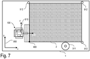
- FIG. 3 is a plan view of a floor surface 1 on which the robot 100 is located, a portion of the floor surface being printed with an image 2.
- Fig. 7 serves to illustrate the printing process carried out with the aid of the robot 100.
- the robot 100 can first be positioned at a starting point 400 and oriented in a desired direction.
- the starting point 400 can be a corner point of the image 2.
- the robot 100 is positioned with a corner of the foremost spray bar 201 at the starting point 400.
- the position of the robot 100 can be defined as the position of the rightmost paint nozzle 210 of the foremost spray bar 201.
- the image 2 to be printed can initially be present as a raster graphic that is stored electronically in an image file.
- Any common file format e.g. JPEG File Interchange Format (JFIF), Portable Network Graphics (PNG), Tagged Image File Format (TIFF), etc.
- JFIF JPEG File Interchange Format
- PNG Portable Network Graphics
- TIFF Tagged Image File Format
- the image file is then using software (Resizer software) in Image data which can be further processed by the robot 100 are converted and stored in a machine-readable file.
- a color separation is carried out first. This means that the color data contained in the image file (e.g. red, green and blue values with 8 bits each for 24 bit color depth) for the individual pixels are converted into corresponding amounts of color of the colorants used (in the colorant containers 110, 111 and 112).
- the raster graphics are also scaled to the required size. The number of pixels is adjusted so that the pixel spacing corresponds to the spacing of the paint nozzles 210 in the spray bar of
- the communication interface can be a USB interface, for example.
- a wireless transmission for example via a WLAN module integrated in the robot 100, is possible.
- other wireless connections e.g. Bluetooth, ZigBee, etc.
- the controller 117 of the robot can, for example, be designed to calculate a travel path of the robot 100 (robot path, trajectory) from the image data and then to control the chassis of the (e.g. chains 102 and 103) with appropriate travel commands so that the robot follows the calculated robot path follows.
- the controller 117 can also generate control commands for the diaphragm pumps 250, 251, 252 and 253 and for the valves 212 in the robot 100 from the image data.
- the amount of paint applied to the floor surface 1 is controlled directly via the valves 212.
- the coordinates x r t and y r t denotes the location of the robot 100 in the global coordinate system of the robot 900 and ⁇ r t the orientation of the robot (angle between the x-axis of the global coordinate system 900 and a local coordinate system 910 moved with the robot).
- Sensor data recorded by the robot are generally available in the local coordinate system 910 of the robot and can be transformed into the global coordinate system via a coordinate transformation.
- the robot 100 has a certain (global) position x ⁇ r t has reached a print command b x ⁇ r t and paint is applied to the floor surface 1 via the spray bars 201, 202, 203. While the robot moves along the previously calculated (eg meandering) path, the image is "printed" 2 pixel by pixel on the floor surface.
- the robot 100 can move along a straight trajectory of a straight path segment, practically any number of image points (pixels) can be printed along an image line, whereby as many image lines can be printed simultaneously as a spray bar has color nozzles (in the examples described above, these are 40 paint nozzles).
- the color nozzles can be controlled (print commands b x ⁇ r t ).
- the robot 100 must regularly determine its position (including orientation) in the global coordinate system 900. This process is also known as localization.
- the robot 100 can evaluate sensor data from one or more sensors.
- One possible method for locating the robot 100 is odometry.
- the robot determines its position based on the distance covered, which in turn can be determined using a rotary encoder on the (chain) wheels, for example. Odometry for determining the position and orientation of mobile robots in a coordinate system is known per se and is therefore not explained further here.
- Odometry based on encoder sensor data is only accurate over short distances and the position determined by the robot can drift away from the actual position (e.g. due to slippage).
- other sensors can be used that implement other measuring principles, such as a camera for camera-based odometry, distance sensors such as laser scanners for SLAM ( Simultaneous Localization on Mapping ), receivers for satellite-based positioning (e.g. GPS location and DGPS location).
- the controller 117 of the robot can be designed to merge sensor data from different sensors (sensor data fusion).
- the means Odometry (by means of rotary encoder) determined position can be regularly corrected based on the sensor data of other sensors (e.g. DGPS receiver).
- the robot can also detect landmarks by means of distance sensors (for example laser scanners), measure the position of the robot 100 relative to the detected landmarks (for example by means of triangulation), and use the position thus determined to correct the odometry.
- Landmarks are generally objects with a known position. In Fig. 7 objects 911 (eg a tree) and objects 912 (eg marker poles with reflectors) are shown.
- the positions of the objects 911 and 912 can be stored by the robot 100 in an electronic map.
- the map can also contain the positions of the individual pixels of the image 2 to be printed.
- the robot controller can generate a print command which activates the valves 212 in the spray bar accordingly.
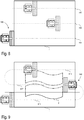
- Figure 8 shows an example of a possible path (trajectory) along which the robot moves when printing image 2.
- the robot path can have several straight path segments 401, 402 and 403, which the robot traverses sequentially.
- the robot 100 moves along the path segments 401, 402 and 403 over the floor area 1.
- Each of the path segments 401, 402 and 403 is driven over in the same direction.
- the robot 100 travels at the end of each path segment 401, 402 to the beginning of the respective next path segment 402, 403.
- the robot path also consists of parallel, straight path segments 611, 612 and 613. Unlike in the previous example, the robot travels through path segments 611, 612 and 613 in a meandering manner.
- the printing method performed by the robot 100 is summarized below. First, the robot 100 is parked at the starting point 400 (cf. Fig. 7 ). Before or after this, as explained above, further processable image data are calculated from an image file for the robot, which image data is transmitted to the controller 117 of the robot 100. Based on this image data, the controller 117 of the robot can plan a robot path along the The robot then moves over the floor area 1.
- the robot While the robot is moving, the robot continuously determines its position (and orientation) in a global coordinate system in which the positions of the individual image points (pixels) are also defined. As soon as the robot reaches a position at which one or more image points are to be printed, the robot controller 117 generates a print command to control the valves 212 in the spray bar 201, 202, 203 (cf. Fig. 1-5 ).
- a "picture element" or pixel can be, for example, an approximately oval or rectangular area with a length in the range from 20 to 38 mm and a width in the range from 10 to 19 mm.
- Each pixel can be individually sprayed with colorant 10 by the robot 100.
- the spray bars 201, 202 and 203 can each apply different colors to the floor surface 1, with different colors (e.g. white, cyan, magenta, yellow and black) being applied one after the other to the same image point (pixel) for a multi-color print.
- a pixel can also be divided into several subpixels, each subpixel being colored with a different color.
- the ink nozzles 210 can be cleaned at regular intervals or at certain events (for example the end of a web segment or after the color has changed, etc.).
- cleaning agent 11 can be passed from cleaning agent container 113 through paint nozzles 210 and paint residues can be removed from paint nozzles 210 (cf. Fig. 5 ).
- cleaning agent 11 can be sprayed onto paint nozzles 211 from outside via cleaning nozzles 214. This also removes paint residues that are in contact with the outside of the nozzles 210. Valves 212 may be closed during cleaning. As a result of regular cleaning, the function of the nozzle assemblies 211 can be maintained over the duration of the entire printing project and a good quality of the finished image 2 can be guaranteed.
- the robot 100 rotates 180 ° and then moves along the path 612 in the opposite direction to the path 611 over the floor area 1 and prints another part of the image 2.
- the robot 100 can be guided exactly along an already printed area will.
- the robot 100 can be equipped with a camera system that forwards the analysis of the already printed areas of the floor area 1 by means of image processing and the information obtained thereby to the controller 117.
- the image processing is essentially designed to compare an already printed partial image recorded by means of a camera with a “target image” and to determine any deviations that may be present.
- the positioning and alignment of the robot 100 can be performed prior to the printing of a further part of the image (for example the partial image to be printed when passing through the second path segment 402, see Fig. 8 ) be improved.
- the robot 100 can (e.g. before printing or also during printing of the second partial image) the partial image previously printed when traveling through the preceding (first) path segment using camera recordings and image processing analyze and align the second path segment (and thus the second partial image) with the first partial image.
- the actual course of the second path segment can deviate from a theoretical target course, since the robot trajectors can be continuously corrected when driving through the second path segment in order to adapt the robot trajectors of the second path segment (and thus the second partial image) to the first partial image.
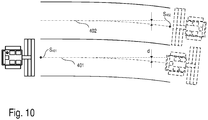
- This situation is in Fig. 10 shown.
- Figure 10 illustrates the above-described adaptation of the robot trajectory of a path segment 402 to the partial image that was printed when the previous path segment 401 was traversed.
- the robot trajectory of the first path segment 401 actually executed when the first partial image is printed begins at a starting point S 401 .
- the value d does not have to be constant. In the present example, the value d increases with increasing distance from the starting point S 401 .
- this deviation can be analyzed by means of a camera and image processing of the printed partial image, and the trajectories in the following path segment 402 can be corrected accordingly by the determined value d.
- This correction can take place once before the start of printing in the second path segment (to determine the starting point S 402 of the trajectory of the second path segment 402) and also be continuously adapted when passing through the second path segment 402 (based on accumulating measurements carried out using a camera and image processing).
- the print commands i.e. those positions at which the printing of a pixel is triggered
- the robot 100 can also be equipped with level sensors in the paint tank 110, 111 and 112 and the detergent tank 113. If the level in one of the containers falls below a predefined level, the controller 117 of the robot 100 can trigger at least one acoustic or visual alarm. As an alternative to this, the controller 117 can also autonomously guide the robot 100 back to the starting point 400 or to another predefined point. As a result, the colorants 10 and the cleaning agent 11 can be refilled in good time and an unplanned termination of a printing process can be prevented. Irregular transitions caused by this in the print motif 2 can thus be prevented and a web 611, 612 and 613 can each be printed seamlessly in one pass.
- images with side lengths of 20 to 150 m can be printed. These images can be divided into smaller sub-images with sides of 30 m each and then printed one after the other. On the basis of the described systems for localizing the robot 100, the robot 100 can "seamlessly" join the individual partial images.
Landscapes
- Engineering & Computer Science (AREA)
- Physics & Mathematics (AREA)
- Radar, Positioning & Navigation (AREA)
- Remote Sensing (AREA)
- Aviation & Aerospace Engineering (AREA)
- General Physics & Mathematics (AREA)
- Automation & Control Theory (AREA)
- Robotics (AREA)
- Optics & Photonics (AREA)
- Electromagnetism (AREA)
- Spray Control Apparatus (AREA)
- Manipulator (AREA)
Description
Die Erfindung betrifft eine Vorrichtung wie z.B. einen autonomen mobilen Roboter oder ein ferngesteuertes Fahrzeug zum pixelweisen Drucken von Bildern auf Bodenflächen.The invention relates to a device such as an autonomous mobile robot or a remote-controlled vehicle for printing images pixel by pixel on ground surfaces.
Beispielsweise im Rahmen von Veranstaltungen (insbesondere Großereignisse wie z.B. im Bereich des Motorsports, Fußball, etc.) besteht ein Bedarf, großflächig Bilder (z.B. Logos von Sponsoren, etc.) auf Bodenflächen aufzutragen. Die Bilder können dabei vergleichsweise groß sein (z.B. über 100 Quadratmeter), so dass sie auch aus der Ferne (z.B. bei Luftaufnahmen) gut zu sehen sind. Ein Bild kann z.B. in Form eines großen Banners auf dem Boden ausgelegt werden. Alternativ dazu, kann ein Bild auch manuell auf die Rasenfläche gesprüht oder gemalt werden, beispielsweise mittels Schablonen und Farbspray. Bei mehrfarbigen Bildern ist dazu ein aufwändiges mehrstufiges Verfahren und der Einsatz mehrerer vorgefertigter Schablonen nötig. Die notwendigen Schablonen sind aufwändig herzustellen und kompliziert in der Handhabung. Darüber hinaus kann es durch manuellen Farbauftrag zu Unregelmäßigkeiten im späteren Erscheinungsbild des Bildes kommen. Die Herstellung großflächiger Bilder bzw. Beschriftungen kann auch für andere Zwecke interessant sein, z.B. Werbung nahe stark frequentierter Straßen (z.B. Autobahnabfahrten, Fußgängerzonen, etc.), die Beschriftung von Flachdächern, Straßen- und Bodenmarkierungen, etc. Aus den Publikationen
Die der Erfindung zugrunde liegende Aufgabe besteht folglich darin, eine Vorrichtung und ein Verfahren zu entwickeln, das ein großflächiges Auftragen von Bildern auf Bodenflächen wie beispielsweise auf Rasen-, Schnee, Asphalt oder Schotterflächen kostengünstig, schnell und zuverlässig ermöglicht.The object on which the invention is based is consequently to develop a device and a method that allows images to be applied over a large area Floor areas such as grass, snow, asphalt or gravel surfaces are inexpensive, quick and reliable.
Die oben genannte Aufgabe wird durch eine Vorrichtung gemäß Anspruch 1 sowie durch ein Verfahren gemäß Anspruch 13 gelöst. Unterschiedliche Ausführungsformen und Weiterentwicklungen der Erfindung sind Gegenstand der abhängigen Ansprüche.The above-mentioned object is achieved by a device according to
Es wird eine Vorrichtung zum Drucken eines Bildes auf eine Bodenfläche beschrieben. Gemäß einer exemplarischen Ausführungsform umfasst die Vorrichtung eine Steuerung und ein Drucksystem. Das Drucksystem weist mindestens einen Farbtank mit Farbmittel und mindestens einen Sprühbalken mit mehreren nebeneinander angeordneten Düsenbaugruppen auf. Die Düsenbaugruppen haben jeweils ein von der Steuerung steuerbares Ventil und eine Farbdüse, über die Farbmittel auf die Bodenfläche aufgetragen werden kann. Das Drucksystem weist außerdem einen Reinigungsmitteltank auf, der über eine oder mehrere Zuleitungen mit zumindest einem Teil der Düsenbaugruppen verbunden ist. Jeder der Düsenbaugruppen weist eine über die Zuleitung versorgte und der jeweiligen Farbdüse zugeordnete Reinigungsdüse auf, die so angeordnet ist, dass Reinigungsmittel von außen auf die Farbdüse gesprüht werden kann. Die Farbdüse ist über ein Ventil mit der Zuleitung verbunden, sodass Reinigungsmittel ins Innere der Farbdüse geleitet und aus der Farbdüse herausgesprüht werden kann.An apparatus for printing an image on a floor surface is described. According to an exemplary embodiment, the device comprises a controller and a printing system. The printing system has at least one ink tank with ink and at least one spray bar with several nozzle assemblies arranged next to one another. The nozzle assemblies each have a valve that can be controlled by the controller and a paint nozzle that can be used to apply paint to the floor surface. The printing system also has a cleaning agent tank which is connected to at least some of the nozzle assemblies via one or more feed lines. Each of the nozzle assemblies has a cleaning nozzle, which is supplied via the supply line and is assigned to the respective paint nozzle, which is arranged such that cleaning agent can be sprayed onto the paint nozzle from the outside. The paint nozzle is connected to the supply line via a valve so that cleaning agent can be directed into the interior of the paint nozzle and sprayed out of the paint nozzle.
Des Weiteren wird ein Verfahren zum Drucken eines Bildes auf eine Bodenfläche mittels einer Vorrichtung beschrieben, die gemäß einer exemplarischen Ausführungsform ein Drucksystem aufweist, das mindestens einen Sprühbalken mit mehreren nebeneinander angeordneten Düsenbaugruppen umfasst. Die Düsenbaugruppen weisen wiederum jeweils ein steuerbares Ventil und eine Farbdüse auf. Das Drucksystem weist außerdem einen Reinigungsmitteltank auf, der über eine oder mehrere Zuleitungen mit zumindest einem Teil der Düsenbaugruppen verbunden ist. Jede der Düsenbaugruppen weist eine über die Zuleitung versorgte und der jeweiligen Farbdüse zugeordnete Reinigungsdüse auf. Die Farbdüse ist über ein Ventil mit der Zuleitung verbunden. Gemäß dieser exemplarischen Ausführungsform umfasst das Verfahren das Durchfahren eines ersten Bahnsegments mit dem mobilen Roboter und das Ansteuern der Ventile der Düsenbaugruppen zum Abgeben von Farbe durch eine dem Ventil zugeordnete Farbdüse. Dabei wird für jeden Bildpunkt und jede Farbe abhängig von der Position des Roboters ein Druckbefehl für die Ventile erzeugt, sodass das Bild pixelweise auf die Bodenfläche aufgetragen wird. Das Verfahren umfasst weiter das regelmäßiges Reinigen der Farbdüsen durch Aufsprühen von Reinigungsmittel auf die Farbdüsen von außen mittels den in den Düsenbaugruppen angeordneten Reinigungsdüsen und das regelmäßiges Reinigen der Farbdüsen durch Leiten ins Innere der Farbdüse und Heraussprühen von Reinigungsmittel aus der Farbdüse.Furthermore, a method for printing an image on a floor surface by means of a device is described which, according to an exemplary embodiment, has a printing system which comprises at least one spray bar with a plurality of nozzle assemblies arranged next to one another. The nozzle assemblies in turn each have a controllable valve and a paint nozzle. The printing system also has a cleaning agent tank which is connected to at least some of the nozzle assemblies via one or more feed lines. Each of the nozzle assemblies has a cleaning nozzle that is supplied via the supply line and assigned to the respective paint nozzle. The paint nozzle is connected to the supply line via a valve. According to this exemplary embodiment, the method comprises traversing a first path segment with the mobile robot and activating the valves of the nozzle assemblies to dispense paint through a paint nozzle assigned to the valve. For each pixel, and each color, depending on the position of the robot, generates a pressure command for the valves, so that the image is applied pixel by pixel on the floor surface. The method further comprises the regular cleaning of the paint nozzles by spraying cleaning agent onto the paint nozzles from the outside by means of the cleaning nozzles arranged in the nozzle assemblies and the regular cleaning of the paint nozzles by guiding them inside the paint nozzle and spraying cleaning agent out of the paint nozzle.
Ein Ausführungsbeispiel betrifft ein Reinigungsverfahren zum Reinigen der Düsenbaugruppen eines Sprühbalkens, wobei jede Düsenbaugruppe eine Farbdüse und eine dieser zugeordneten Reinigungsdüse aufweist. Das Verfahren umfasst das Zuführen von Reinigungsmittel zu der Reinigungsdüse, sodass Reinigungsmittel aus der Reinigungsdüse austritt und von außen auf die Farbdüse gesprüht wird und das Zuführen von Reinigungsmittel ins Innere der Farbdüse, sodass das Reinigungsmittel aus der Farbdüse austritt.One embodiment relates to a cleaning method for cleaning the nozzle assemblies of a spray bar, each nozzle assembly having a paint nozzle and a cleaning nozzle assigned to it. The method comprises supplying detergent to the cleaning nozzle so that detergent emerges from the cleaning nozzle and is sprayed onto the paint nozzle from the outside and supplying detergent inside the paint nozzle so that the detergent emerges from the paint nozzle.
Die Erfindung wird nachfolgend anhand von den in den Figuren dargestellten Beispielen näher erläutert. Die Darstellungen sind nicht zwangsläufig maßstabsgetreu und die Erfindung beschränkt sich nicht nur auf die dargestellten Ausführungsbeispiele und Aspekte. Vielmehr wird Wert darauf gelegt, die der Erfindung zugrunde liegenden Prinzipien darzustellen. In den Figuren bezeichnen gleiche Bezugszeichen gleiche oder ähnliche Komponenten mit gleicher bzw. ähnlicher Bedeutung bzw. Funktion.
-
Figur 1 -
Figur 2Fig. 1 anhand einer Darstellung von unten (Untersicht). -
Figur 3Fig. 1 anhand einer Darstellung von vorne (Ansicht). -
Figur 4 zeigt anhand eines schematischen Diagramms exemplarisch die Funktionsweise einer Druckereinheit (Sprühbalken) mit einer Vielzahl von Düsen zum pixelweisen Auftragen von Farbe. -
Figur 5 ist eine schematische Darstellung einer in einem Sprühbalken enthaltenen Düsen zum Auftragen von Farbe. -
Figur 6 zeigt einen schematischen Aufbau eines Beispiels eines Sprühmoduls, wobei ein Sprühbalken aus einem oder mehreren aneinandergereihten Sprühmodulen aufgebaut sein kann. -
Figur 7Fig. 1-3 . -
Figur 8 zeigt anhand einer exemplarischen Draufsicht den Fahrweg (Trajektorie) des Roboters über einen Druckbereich. -
Figur 9 zeigt weiteres Beispiel einer Robotertrajektorie über den Druckbereich. -
Figur 10
-
Figure 1 shows an example of a robot for printing floor surfaces on the basis of a schematic representation from above (top view). -
Figure 2 shows the robot according toFig. 1 based on a representation from below (bottom view). -
Figure 3 shows the robot according toFig. 1 based on a representation from the front (view). -
Figure 4 shows, based on a schematic diagram, the mode of operation of a printer unit (spray bar) with a large number of nozzles for the pixel-by-pixel application of color. -
Figure 5 Figure 3 is a schematic representation of a nozzle included in a spray bar for applying paint. -
Figure 6 shows a schematic structure of an example of a spray module, wherein a spray bar can be made up of one or more spray modules lined up. -
Figure 7 uses a representation from above to illustrate the printing of a floor surface by means of the robot according to FIGFig. 1-3 . -
Figure 8 shows the path (trajectory) of the robot over a pressure area on the basis of an exemplary top view. -
Figure 9 shows another example of a robot trajectory over the pressure area. -
Figure 10 illustrates the adaptation of the robot trajectory of a path segment to the partial image that was printed when driving through the previous path segment.
Die Ketten oder die Räder sind beispielsweise mit einem Elektromotor angetrieben, der über einen im Roboter 100 angeordnete Batterie mit Energie versorgt wird. Andere Antriebsarten sind möglich. Im oder auf dem Gehäuse 101 können zumindest ein Farbmittelbehälter (z.B. Farbtanks 110, 111 und 112), ein Reinigungsmittelbehälter (Reinigungsmitteltank 113), ein elektrischer Konverter 116 (Strom-/Spannungswandler) und eine Steuerung 117 angeordnet sein. Abhängig von der verwendeten Batterie und den elektrischen Eigenschaften des Antriebs kann der Konverter 116 auch entfallen. Optional kann die Steuerung 117 dazu aus gebildet sein, mit Hilfe einer Antenne 118 Steuerbefehle zu empfangen oder Statusinformationen (beispielsweise über einen Ladezustand der Batterie oder den Fortschritt des Druckprozesses) zu senden. Die Antenne 118 kann beispielsweise eine WLAN-Antenne sein. Der Konverter 116 ist z.B. ein DC/DC-Wandler zum Umwandeln der Batteriespannung in die für den Betrieb des Roboters nötige Betriebsspannung (z.B. 24 V) umzuwandeln. Die Farbtanks 110, 111 und 112 sowie der Reinigungsmitteltank 113 können austauschbare Kunststoffbehälter sein. Für einen raschen Tausch der Tanks können diese z.B. mit Schnellwechselverschlüssen am Gehäuse (direkt oder indirekt) befestigt sein.The chains or the wheels are driven, for example, by an electric motor that is supplied with energy via a battery arranged in the
Ganz allgemein kann die Steuerung 117 dazu ausgebildet sein, den Roboter autonom über die Bodenfläche zu navigieren. Alternativ kann die Steuerung 117 den Roboter nach Maßgabe von Steuerbefehlen bewegen, die von einer Fernsteuerung empfangen werden, die von einer Bedienperson bedient wird. Die Steuerung kann dazu Fahrassistenzfunktionen zur Verfügung stellen, die eine zumindest teilweise selbsttätige Navigation der Vorrichtung ermöglichen. Gesetzliche Bestimmungen können vorschreiben, dass ein Fahrer mit dem Fahrzeug mitfährt. Die Vorrichtung bzw. der Roboter bewegt sich dabei entlang einer Trajektorie. Die Bahn des Roboters kann dabei in mehrere Bahnsegmente unterteilt sein, in denen die Trajektorie im Wesentlichen geradlinig verlaufen kann. Beim Durchfahren eines dieser Bahnsegmente werden mehrere Bildzeilen eines Teilbildes des zu druckenden Bildes pixelweise auf die Bodenfläche gedruckt. Beim Durchfahren des nächsten, zum ersten Bahnsegment benachbarten Bahnsegmentes werden mehrere Bildzeilen eines weiteren Teilbildes des zu druckenden Bildes pixelweise auf die Bodenfläche gedruckt. Eine Herausforderung bei der Steuerung des Roboters besteht darin, die Teilbilder möglichst "nahtlos" nebeneinander zu drucken.In general, the
Die Vorrichtung/der Roboter 100 kann Sensoren zur Bestimmung der eigenen Position (Ort und Lage) aufweisen. Die Sensoren zur Positionsbestimmung können auf unterschiedlichen Messprinzipien beruhen, beispielsweise Odometrie (z.B. mittels eines oder mehrerer Radumdrehungssensoren), kamerabasierte Odometrie, Positionsbestimmun mittels GPS (z.B. differentielles GPS), etc. Über einen Ausleger 120 können am Roboter 100 (z.B. an dessen Karosserie) Sprühbalken 201, 202, 203 befestigt sein, die auch als Sprühbalken bezeichnet werden. Der Ausleger 120 hält die Sprühbalken 201, 202, 203 in einem definierten Abstand über der zu bedruckenden Oberfläche. Dieser Abstand kann einstellbar sein. Dazu kann der Roboter z.B. einen Aktor (nicht dargestellt) aufweisen, der den Ausleger 120 schwenken und damit die Sprühbalken 201, 202, 203 anheben oder absenken kann. Die Sprühbalken 201, 202, 203 können separate Komponenten sein oder auch zu einem Bauteil verbunden sein.The device / the
Am zweiten Ende des Hebearmes 120 kann zumindest eine Düsenbaugruppe 210 angebracht sein. Fünf Düsenbaugruppen 210 können ein Düsenmodul bilden und mehrere Düsenmodule können jeweils einen Düsenbalken 201, 202 oder 203 bilden. Im dargestellten Beispiel weist der Roboter 100 drei Düsenbalken 201, 202 und 203 mit jeweils 40 Düsenbaugruppen auf. Jeder Sprühbalken kann aus einem oder mehreren Sprühmodulen bestehen, wobei jedes Sprühmodul mehrere Düsen aufweist, über die Farbe auf die Bodenfläche gesprüht werden kann. Jede Düse färbt genau einen Pixel des zu druckenden Bilds mit einer bestimmten Farbe ein. Bei einem Mehrfarbendruck wird jedes Pixel des zu druckenden Bildes entsprechend mehrfach mit unterschiedlichen Farben eingefärbt. Gemäß einer exemplarischen Implementierung umfasst ein Sprühbalken acht Sprühmodule mit jeweils fünf Düsen, sodass ein Sprühbalken vierzig Düsen aufweist und folglich vierzig Pixel in einer Reihe gleichzeitig einfärben kann.At least one
In
Mit den drei Sprühbalken 201, 202, 203, kann ein Dreifarbdruck realisiert werden, wobei mittels subtraktiver Farbmischung für jeder einzelne Pixel mit einer bestimmten Farbe eingefärbt werden kann. Dazu kann beispielsweise der Sprühbalken 201 mit magenta Farbmittel, der Sprühbalken 202 mit gelbem Farbmittel und der Sprühbalken 203 mit cyanem Farbmittel versorgt werden. Während der Roboter 100 sich vorwärtsbewegt, können die einzelnen Pixel mit definierter Position auf der Bodenfläche 1 nacheinander magenta, gelb und cyan eingefärbt werdend. Die über die einzelnen Düsen abgegebene Farbstoffmenge ist steuerbar. Das Verhältnis der Farbmengen magenta/gelb/cyan bestimmt den Farbton und die absolute Farbmenge die Farbsättigung. An dieser Stelle sei angemerkt, dass auch ein vierter Sprühbalken mit schwarzer oder weißer Farbe verwendet werden kann. Es können auch mehr als drei Sprühbalken vorgesehen sein, um einen Mehrfarbendruck zu realisieren, beispielsweise fünf Sprühbalken für die Farben Cyan, Magenta, Gelb, Schwarz und Weiß, um eine Farbmischung gemäß dem CMYK-Farbmodell zu ermöglichen (je nach Farbe der Bodenfläche kann auch eine weiße Farbe nötig sein).With the three
Das Drucksystem 200 des Roboters 100 ist exemplarisch in
Die Saugseiten der Membranpumpen 250, 251 und 252 sind hydraulisch mit den Farbtanks 110, 111, 112 verbunden, die Druckseiten mit den Sprühbalken 201, 202, 203. Optional, können zwischen den Druckseiten der Membranpumpen 250, 251, 252 und den Farbtanks 110, 111, 112 jeweils Überströmventile 260, 261, 262 angeordnet sein. Über die Überströmventile 260, 261, 262 kann überschüssige Farbe zurück in den jeweiligen Farbtank geleitet werden. Dies kann dann der Fall sein, wenn die Membranpumpen mehr Farbe fördern als über den Sprühbalken abgegeben wird. Auf diese Weise können die Überströmventile 260, 261, 262 eine Überlastung der Membranpumpen 250, 251, 252 verhindern. Die Membranpumpen 250, 251 und 252 können außerdem Pulsationsdämpfer aufweisen, die eine gleichmäßige Förderung der Farbmittel aus den Farbtanks sicherstellen.The suction sides of the diaphragm pumps 250, 251 and 252 are hydraulically connected to the
Die Förderung von Reinigungsmittel aus dem Reinigungsmitteltank 113 hin zu den Sprühbalken 201, 202, 203 kann in gleicher Weise realisiert werden wie die Förderung von Farbe. Für diesen Fall gilt das, was in Bezug auf die Membranpumpen 250, 251, 252 zur Förderung von Farbe aus den Farbtanks gesagt wurde, auch für die Membranpumpe 253 zur Förderung von Reinigungsmittel aus dem Reinigungsmitteltank 113. Auch die Membranpumpe 253 kann mit einem Überströmventil 263 kombiniert werden, um eine Überlastung der Membranpumpe 253 zu verhindern und überschüssiges Reinigungsmittel in den Reinigungsmitteltank 113 zurück zu leiten. In diesem Zusammenhang sei angemerkt, dass auch andere Typen von Pumpen verwendet werden können. Es sind auch Drucksysteme möglich, die ohne Pumpen auskommen. In diesem Fall könnten z.B. die Farbtanks unter Druck gesetzt werden (z.B. mittels Pressluft). Ganz allgemein muss das Drucksystem 200 Komponenten enthalten, die dazu ausgebildet sind, den Sprühbalken (oder den einzelnen Sprühmodulen) Farbe und Reinigungsmittel mit einem definierten Druck zur Verfügung zu stellen.The delivery of cleaning agent from the
In dem Sprühbalken 201 sind die einzelnen Farbdüsen 210 angeordnet (vgl. auch
In dem Beispiel aus
Der Einlass der Reinigungsmitteldüse 214 kann über die Zuleitung 217 mit dem Reinigungsmittelbehälter 213 verbunden sein und von diesem mit Reinigungsmittel 11 versorgt werden. Die Reinigungsmitteldüse 214 kann auf die Farbmitteldüse 211 gerichtet sein, sodass das von der Reinigungsmitteldüse 214 austretende Reinigungsmittel 11 von außen auf die Farbdüse 210 gesprüht wird und diese von Farbrückständen gereinigt wird. Der Einlass der Farbdüse 210 kann zusätzlich über das Rückschlagventil 215 ebenfalls mit der Zuleitung 217 verbunden sein, sodass bei der Reinigung das Reinigungsmittel 11 auch durch die Farbdüse 210 strömt und diese innen reinigt. Beim Drucken verhindert das Rückschlagventil 215, dass Farbe hin zur Zuleitung 217 für das Reinigungsmittel fließen kann.The inlet of the
Das zu druckende Bild 2 kann zunächst als Rastergrafik vorliegen, die elektronisch in einer Bild-Datei gespeichert ist. Jedes übliche Dateiformat (z.B. JPEG File Interchange Format (JFIF), Portable Network Graphics (PNG), Tagged Image File Format (TIFF), etc.) ist möglich. Die Bild-Datei wird dann mithilfe einer Software (Resizer-Software) in für den Roboter 100 weiter verarbeitbare Bilddaten umgewandelt und in einer maschinenlesbaren Datei gespeichert. Dabei wird zuerst eine Farbseparation durchgeführt. Das heißt, dass die in der Bilddatei enthaltenen Farbdaten (z.B. Rot- Grün- und Blauwerte mit jeweils 8 Bit für 24 Bit Farbtiefe) zu den einzelnen Pixeln werden in entsprechende Farbmengen der verwendeten Farbmittel (in den Farbmittelbehältern 110, 111 und 112) umgerechnet. Des Weiteren wird die Rastergrafik auf die gewünschte Größe skaliert. Dabei wird Anzahl der Pixel so angepasst, dass bei der gewünschten Bildgröße der Pixelabstand dem Abstand der Farbdüsen 210 in den Sprühbalken des Roboters 100 entspricht.The
Diese für den Roboter verarbeitbaren Bilddaten können mittels einer Kommunikationsschnittstelle an die Steuerung 117 (siehe
Da das zu druckende Bild 2 in der Regel eine Rastergrafik ist, ist durch das Bild auch ein globales, ortsfestes (kartesisches) Koordinatensystem 900 definiert. Dieses Koordinatensystem kann von der Robotersteuerung 117 auch verwendet, um den Roboter 100 über die Bodenfläche zu navigieren. Dazu benötigt die Robotersteuerung die Position ![]()
![]()
![]()
![]()
![]()
![]()
![]()
![]()
![]()
![]()
![]()
![]()
![]()
![]()
Solange der Roboter 100 sich entlang einer geradlinigen Trajektorie eines geradlinigen Bahnsegments bewegt, können praktisch beliebig viele Bildpunkte (Pixel) entlang einer Bildzeile gedruckt werden, wobei so viele Bildzeilen gleichzeitig gedruckt werden können, wie ein Sprühbalken Farbdüsen hat (in den oben beschriebenen Beispielen sind das 40 Farbdüsen). Um ein regelmäßiges Bild zu erzeugen, müssen in regelmäßigen Abständen die Farbdüsen (über die Ventile 212, siehe ![]()
![]()
Odometrie basierend auf Drehgeber-Sensordaten ist nur auf kurze Distanzen genau und die vom Roboter ermittelte Position kann von der tatsächlichen Position wegdriften (z.B. aufgrund von Schlupf). Um die Genauigkeit der Lokalisierung zu verbessern, können neben den Drehgebern noch weitere Sensoren verwendet werden, die andere Messprinzipien umsetzen, wie z.B. eine Kamera für kamerabasierte Odometrie, Abstandssensoren wie z.B. Laserscanner für SLAM (Simultaneous Lokalisation an Mapping), Empfänger für satellitengestützte Ortung (z.B. GPS-Ortung und DGPS-Ortung). Zur Verbesserung der Genauigkeit kann die Steuerung 117 des Roboters dazu ausgebildet sein, Sensordaten verschiedener Sensoren zu fusionieren (Sensordatenfusion). Beispielsweise kann die mittels Odometrie (mittels Drehgeber) ermittelte Position regelmäßig basierend auf den Sensordaten anderer Sensoren (z.B. DGPS-Empfänger) korrigiert werden. Der Roboter kann auch mittels Abstandssensoren (z.B. Laserscanner) Landmarken detektieren, die Position des Roboters 100 relativ zu den detektierten Landmarken messen (z.B. mittels Triangulation), und die so ermittelte Position zur Korrektur der Odometrie verwenden. Landmarken sind ganz allgemein Objekte mit bekannter Position. In
Mit künstlich angebrachten und an das Gelände angepassten Objekten 912 kann z.B. sichergestellt werden, dass auch in z.B. hügeligem Gelände genügend Landmarken im Erfassungsbereich der Sensoren des Roboters befinden, um eine Lokalisierung durchzuführen. Die Positionen der Objekte 911 und 912 können vom Roboter 100 in einer elektronischen Karte abgespeichert werden. Die Karte kann auch die Positionen der einzelnen Pixel des zu druckenden Bildes 2 enthalten. Sobald der Roboter eine Position erreicht hat, an der eine bestimmte Gruppe von Bildpunkten gedruckt werden soll, kann die Robotersteuerung einen Druckbefehl erzeugen, der die Ventile 212 in den Sprühbalken entsprechend ansteuert.With artificially attached
In dem Beispiel gemäß
Ein "Bildpunkt" bzw. Pixel kann z.B. eine annähernd ovale oder rechteckige Fläche mit einer Länge im Bereich von 20 bis 38 mm und einer Breite im Bereich von 10 bis 19 mm sein. Jeder Pixel kann vom Roboter 100 einzeln mit Farbmittel 10 besprüht werden. Die Sprühbalken 201, 202 und 203 können jeweils unterschiedliche Farben auf die Bodenfläche 1 auftragen, wobei für einen Mehrfarbendruck auf den gleichen Bildpunkt (Pixel) hintereinander unterschiedliche Farben (z.B. weiß, cyan, magenta, gelb und schwarz) aufgetragen werden. Alternativ kann ein Pixel auch in mehrere Subpixel unterteilt werden, wobei jeder Subpixel mit einer anderen Farbe eingefärbt wird.A "picture element" or pixel can be, for example, an approximately oval or rectangular area with a length in the range from 20 to 38 mm and a width in the range from 10 to 19 mm. Each pixel can be individually sprayed with
In regelmäßigen Abständen oder bei beistimmten Ereignissen (z.B. Ende eines-Bahnsegments oder nach dem Wechseln der Farbe, etc.) kann jeweils eine Reinigung der Farbdüsen 210 durchgeführt werden. Dazu kann Reinigungsmittel 11 aus dem Reinigungsmittelbehälter 113 durch die Farbdüsen 210 geleitet werden und Farbmittelreste von den Farbdüsen 210 entfernt werden (vgl.
Mit Hilfe einer kamerabasierten Analyse des bereits bedruckten Bereiches (z.B. das beim Durchfahren des ersten Bahnsegments 401 erzeugte Teilbild, siehe
Der Roboter 100 kann außerdem mit Füllstandsensoren in den Farbtank 110, 111 und 112 und dem Reinigungsmitteltank 113 ausgestattet sein. Beim Unterschreiten eines vordefinierten Füllstandes in einem der Behälter kann von der Steuerung 117 des Roboters 100 zumindest ein akustischer oder optischer Alarm ausgelöst werden. Alternativ dazu kann die Steuerung 117 den Roboter 100 auch zum Startpunkt 400 oder zu einem anderen vordefinierten Punkt autonom zurückführen. Dadurch können die Farbmittel 10 sowie das Reinigungsmittel 11 rechtzeitig nachgefüllt werden und ein ungeplanter Abbruch eines Druckvorganges verhindert werden. Somit können dadurch verursachte unregelmäßige Übergänge im Druckmotiv 2 verhindert werden und eine Bahn 611, 612 und 613 jeweils nahtlos in einem Durchgang bedruckt werden.The
Mit dem beschriebenen Roboter 100 und den beschriebenen Verfahren können Bilder mit Seitenlängen von 20 bis 150 m gedruckt werden. Diese Bilder können in kleinere Teilbilder mit Seitenlängen von jeweils 30 m unterteilt und dann nacheinander gedruckt werden. Aufgrund der beschriebenen Systeme zur Lokalisierung des Roboters 100 kann der Roboter 100 die einzelnen Teilbilder "nahtlos" aneinanderfügen.With the
Claims (15)
- A device (100) for printing an image (2) onto a floor surface (1), wherein the device (100) comprises a controller (117) and a printing system (200), which includes the following:at least one colorant tank (110, 111, 112) having colorant (10);at least one spray bar (201, 202, 203) having multiple nozzle assemblies (211) arranged adjacent to one another, which each have a valve (212) controllable by the controller (117) and a colorant nozzle (210), via which the colorant (10) can be applied to the floor surface (1), anda cleaning agent tank (113), which is connected via one or more supply lines (217) to at least a part of the nozzle assemblies (211),wherein each of the nozzle assemblies (211) has a cleaning nozzle (214), which is supplied via the supply line (217) and associated with the respective colorant nozzle (210, 220, 230) and which is arranged so that cleaning agent can be sprayed from the outside onto the colorant nozzle (210, 220, 230), andwherein the colorant nozzle (210, 220, 230) is connected via a valve (215) to the supply line (217), so that cleaning agent can be conducted into the interior of the colorant nozzle (210, 220, 230) and sprayed out of the colorant nozzle.
- The device as claimed in claim 1,
wherein the controller (117) is designed to individually activate the valves (212) of the individual nozzle assemblies (211) in dependence on the position of the device on the floor surface (1) in such a way that the image (2) is applied pixel by pixel to the floor surface (1). - The device as claimed in one of claims 1 or 2,
wherein the distance of two adjacent nozzle assemblies (211) has a distance which corresponds to the distance of two adjacent image lines of the image (2). - The device as claimed in any one of claims 1 to 3, wherein the controller (117) is designed to navigate the device along a trajectory over the floor surface (1) and at the same time to continuously activate the valves (212) in order to produce individual pixels of multiple image lines (2) on the floor surface (1) via the colorant nozzles (210).
- The device as claimed in claim 4,
wherein the trajectory of the device extends approximately linearly in two or more adjacent path segments and the controller (117) is designed to print adjacent partial images of the image (2) in each case during the travel through the trajectory in the adjacent path segments. - The device as claimed in claim 3 or 5,
wherein at least one camera is coupled to the controller (117), using which a partial image of the image (2) printed during the travel through a first path segment can be acquired, and wherein the controller (117) is designed to adapt the trajectory of the device in a second path segment based on the recorded partial image. - The device as claimed in claim 6,
wherein the controller (117) is designed to determine a starting point (S402) of the trajectory of the device in the second path segment based on the recorded partial image. - The device as claimed in any one of claims 1 to 7, which furthermore
comprises one or more sensors, which acquire sensor data relating to the position or the movement of the device, wherein the controller (117) is designed to determine a position and orientation of the device from the acquired sensor data. - The device as claimed in claim 8,
wherein the controller (117) is designed to fuse the sensor data acquired by two or more sensors to determine the position and the orientation of the device. - The device as claimed in claim 8 or 9,
wherein one of the sensors is a sensor for detecting landmarks in the surroundings, wherein the sensor ascertains the relative position of the device in relation to a landmark, and
wherein the controller (117) is designed to ascertain the position of the device based on the ascertained relative positions and the known positions of the landmarks. - The device as claimed in claim 8,
wherein the controller (117) is designed to generate printing commands for the printing system (200) in dependence on the position of the device, wherein the valves (212) of the individual nozzle assemblies (211) are activated by means of the printing commands. - The device as claimed in any one of claims 1 to 11, wherein one spray bar (201, 202, 203) is provided per colour, the spray bars (201, 202, 203) are arranged essentially in parallel to one another and the nozzle assemblies (211) of the spray bars (201, 202, 203) are arranged essentially along a line.
- A method for printing an image (2) onto a floor surface by means of a device (100) using a printing system, which includes at least one spray bar (201, 202, 203) having multiple nozzle assemblies (211) arranged adjacent to one another, which each include a controllable valve (212) and a colorant nozzle (210), and a cleaning agent tank (113), which is connected via one or more supply lines (217) to at least a part of the nozzle assemblies (211), wherein each of the nozzle assemblies (211) includes a cleaning nozzle (214), which is supplied via the supply line (217) and is associated with the respective colorant nozzle (210, 220, 230), wherein the colorant nozzle (210, 220, 230) is connected via a valve (215) to the supply line (217); the method includes:traveling through a first path segment (401) using the device (100);activating the valves (212) of the nozzle assemblies (211) to dispense colorant through a colorant nozzle (210) associated with the valve (212),wherein a printing command for the valves (212) is generated for each pixel and each colour in dependence on the position of the device (100), so that the image (2) is applied pixel by pixel to the floor surface (1),regularly cleaning the colorant nozzles (210) by spraying cleaning agent on the colorant nozzles from the outside by means of the cleaning nozzles (214) arranged in the nozzle assemblies (211), andregularly cleaning the colorant nozzles (210) by conducting cleaning agent into the interior of the colorant nozzle (210, 220, 230) and spraying it out of the colorant nozzle (210, 220, 230) .
- The method as claimed in claim 13,
wherein the cleaning is carried out after the device has travelled through the trajectory in the first path segment (401) and before it travels through a further path segment (402). - The method as claimed in claim 13 or 14, which furthermore includes:acquiring a partial image of the image (2) printed during the travels of the first path segment (401) by means of a camera;adapting a trajectory of the device (100) in a second path segment (402), which follows the first path segment (402), based on the recorded partial image.
Applications Claiming Priority (2)
| Application Number | Priority Date | Filing Date | Title |
|---|---|---|---|
| DE102016123731.0A DE102016123731B4 (en) | 2016-12-07 | 2016-12-07 | Robot for printing images on floor surfaces |
| PCT/AT2017/060329 WO2018102846A1 (en) | 2016-12-07 | 2017-12-07 | Device for printing images on floor surfaces |
Publications (2)
| Publication Number | Publication Date |
|---|---|
| EP3551345A1 EP3551345A1 (en) | 2019-10-16 |
| EP3551345B1 true EP3551345B1 (en) | 2021-01-20 |
Family
ID=60888054
Family Applications (1)
| Application Number | Title | Priority Date | Filing Date |
|---|---|---|---|
| EP17822540.5A Active EP3551345B1 (en) | 2016-12-07 | 2017-12-07 | Device for printing a picture onto a floor surface |
Country Status (6)
| Country | Link |
|---|---|
| US (1) | US11090672B2 (en) |
| EP (1) | EP3551345B1 (en) |
| CN (1) | CN110325287A (en) |
| AU (1) | AU2017371377A1 (en) |
| DE (1) | DE102016123731B4 (en) |
| WO (1) | WO2018102846A1 (en) |
Families Citing this family (43)
| Publication number | Priority date | Publication date | Assignee | Title |
|---|---|---|---|---|
| DE102016014944A1 (en) | 2016-12-14 | 2018-06-14 | Dürr Systems Ag | Coating method and corresponding coating device |
| DE102016014919A1 (en) | 2016-12-14 | 2018-06-14 | Dürr Systems Ag | Application device and method for applying a coating agent |
| DE102016014953A1 (en) | 2016-12-14 | 2018-06-14 | Dürr Systems Ag | Painting plant and corresponding painting process |
| DE102016014948A1 (en) | 2016-12-14 | 2018-06-14 | Dürr Systems Ag | Printhead and related operating procedures |
| DE102016014946A1 (en) | 2016-12-14 | 2018-06-14 | Dürr Systems Ag | Printhead for applying a coating agent to a component |
| DE102016014955A1 (en) | 2016-12-14 | 2018-06-14 | Dürr Systems Ag | Coating device and corresponding coating method |
| DE102016014947A1 (en) | 2016-12-14 | 2018-06-14 | Dürr Systems Ag | Printhead for applying a coating agent |
| DE102016014951A1 (en) | 2016-12-14 | 2018-06-14 | Dürr Systems Ag | Coating device and associated operating method |
| DE102016014956A1 (en) | 2016-12-14 | 2018-06-14 | Dürr Systems Ag | Coating device and associated operating method |
| DE102016014952A1 (en) | 2016-12-14 | 2018-06-14 | Dürr Systems Ag | Coating device for coating components |
| DE102016014920A1 (en) | 2016-12-14 | 2018-06-14 | Dürr Systems Ag | Printhead with sliding and / or rotating mechanism for at least one row of nozzles |
| DE102016014943A1 (en) | 2016-12-14 | 2018-06-14 | Dürr Systems Ag | Printhead with tempering device |
| US12526374B1 (en) * | 2017-04-20 | 2026-01-13 | Newtonoid Technologies, L.L.C. | Mobile printer |
| US12539525B2 (en) | 2017-11-30 | 2026-02-03 | Axalta Coating Systems Ip Co., Llc | Coating compositions for application utilizing a high transfer efficiency applicator and methods and systems thereof |
| KR102634160B1 (en) | 2017-11-30 | 2024-02-06 | 악살타 코팅 시스템즈 게엠베하 | Systems for applying coating compositions utilizing a high transfer efficiency applicator, coating layers and corresponding methods |
| US11872580B2 (en) * | 2018-01-30 | 2024-01-16 | Ford Motor Company | Composite ultrasonic material applicators with embedded shaping gas micro-applicators and methods of use thereof |
| US11222147B2 (en) | 2018-02-21 | 2022-01-11 | Image Clone, Llc | System and method for automated layout of buildings |
| CN109261407B (en) * | 2018-10-19 | 2021-07-16 | 飞码机器人私人有限公司 | A surface coating robot operating system and method |
| US20240149464A1 (en) * | 2018-11-21 | 2024-05-09 | Dusty Robotics, Inc. | Mobile Printing Robot & Related Methods |
| US11577397B2 (en) | 2019-08-12 | 2023-02-14 | Dusty Robotics, Irc. | Position accuracy robotic printing system |
| EP4028220B1 (en) | 2019-09-13 | 2025-11-05 | Dusty Robotics, Inc. | Mobile robot printing with wind protection and method |
| JP7401277B2 (en) * | 2019-12-04 | 2023-12-19 | ファナック株式会社 | robot programming device |
| CN113431301B (en) * | 2020-03-20 | 2022-04-12 | 广东博智林机器人有限公司 | Method, device, electronic device and storage medium for determining spraying path |
| US12122932B2 (en) | 2020-05-29 | 2024-10-22 | Axalta Coating Systems Ip Co., Llc | Coating compositions for application utilizing a high transfer efficiency applicator and methods and systems thereof |
| CN111907215A (en) * | 2020-08-06 | 2020-11-10 | 王金星 | Environment-friendly operation system based on mobile Internet of things |
| FR3115716B1 (en) * | 2020-11-05 | 2023-12-22 | Exel Ind | METHOD AND INSTALLATION FOR APPLYING A COATING PRODUCT TO A SURFACE |
| JP7764177B2 (en) * | 2021-09-24 | 2025-11-05 | 株式会社トプコン | Marking device, control method and program for marking device |
| DE102021133047A1 (en) | 2021-12-14 | 2023-06-15 | Homag Gmbh | Printing device and method for printing a workpiece |
| WO2023180761A2 (en) | 2022-03-24 | 2023-09-28 | Micropply Limited | An improved navigation system for an autonomous mobile robot (amr) |
| GB202204971D0 (en) | 2022-04-05 | 2022-05-18 | Micropply Ltd | Ground marking robot, method of ground marking using a guide |
| GB2616895A (en) | 2022-03-24 | 2023-09-27 | Micropply Ltd | Autonomous deposition machine with improved deposition layout features |
| GB2617090A (en) | 2022-03-29 | 2023-10-04 | Micropply Ltd | Improved ground deposition robot deposition accounting for overspray |
| WO2023187367A1 (en) * | 2022-03-29 | 2023-10-05 | Micropply Limited | Improved deposition mapping layout for an autonomous ground deposition machine and method thereof |
| US12521748B2 (en) | 2022-04-06 | 2026-01-13 | Micropply Limited | Ground deposition machine for sloping surfaces |
| WO2023194740A1 (en) | 2022-04-06 | 2023-10-12 | Micropply Limited | A detachable ground deposition accessory |
| US20250222482A1 (en) | 2022-04-06 | 2025-07-10 | Micropply Limited | Improved deposition arrangement for a ground deposition machine |
| GB202205018D0 (en) | 2022-04-06 | 2022-05-18 | Micropply Ltd | Autonomous ground deposition machine with multiple accessory means |
| US20250222341A1 (en) | 2022-04-06 | 2025-07-10 | Micropply Limited | A coupling arrangement for a detachable ground deposition accessory |
| WO2024039862A1 (en) * | 2022-08-19 | 2024-02-22 | Rugged Robotics Inc. | Mobility platform for autonomous navigation of worksites |
| WO2024064685A1 (en) * | 2022-09-19 | 2024-03-28 | Dusty Robotics, Inc. | System and method for dual stage control of field printer robot |
| TWI815730B (en) * | 2022-11-16 | 2023-09-11 | 樹德科技大學 | Road drawing device |
| WO2024218291A1 (en) * | 2023-04-20 | 2024-10-24 | Sika Technology Ag | Autonomous mobile spraying apparatus |
| CN117506898A (en) * | 2023-11-06 | 2024-02-06 | 珠海格力电器股份有限公司 | Tag construction methods, devices, cleaning robots and storage media |
Family Cites Families (19)
| Publication number | Priority date | Publication date | Assignee | Title |
|---|---|---|---|---|
| GB2266863A (en) * | 1992-05-15 | 1993-11-17 | Charles Francis Thompson | Selective marking of large areas such as landscapes. |
| US6330503B1 (en) * | 1999-02-22 | 2001-12-11 | Trimble Navigation Limited | Global positioning system controlled staking apparatus |
| FR2814395B1 (en) * | 2000-09-26 | 2003-03-28 | Imaje Sa | METHOD AND DEVICE FOR CLEANING NOZZLES FOR INK-JET PRINTERS, AND PRINT HEAD AND PRINTER INCORPORATING SUCH A DEVICE |
| DE10202553A1 (en) | 2002-01-24 | 2003-08-07 | Burkhard Buestgens | Method of applying paints or varnishes |
| JP5195128B2 (en) * | 2008-07-31 | 2013-05-08 | セイコーエプソン株式会社 | Recording apparatus and recording apparatus control method |
| US20120325924A1 (en) * | 2009-11-04 | 2012-12-27 | American Roadprinting, Llc | Apparatus and method for applying a fluid to a surface |
| WO2011099547A1 (en) * | 2010-02-12 | 2011-08-18 | 本田技研工業株式会社 | Cleaning apparatus and cleaning method for coating gun |
| CN102019252B (en) * | 2010-06-01 | 2013-02-20 | 陈尚文 | Gas atomizing and spraying device |
| EP2799150B1 (en) * | 2013-05-02 | 2016-04-27 | Hexagon Technology Center GmbH | Graphical application system |
| EP2433716A1 (en) * | 2010-09-22 | 2012-03-28 | Hexagon Technology Center GmbH | Surface spraying device with a nozzle control mechanism and a corresponding method |
| US20120186606A1 (en) * | 2011-01-20 | 2012-07-26 | Barss Steven H | Cleaning of Nozzle Plate |
| EP2641661B1 (en) * | 2012-03-20 | 2016-05-11 | Hexagon Technology Center GmbH | Graphical application system |
| US9598826B2 (en) * | 2012-10-30 | 2017-03-21 | Capstan Ag Systems, Inc. | Paint spraying system |
| ES2537222A1 (en) | 2013-07-16 | 2015-06-03 | Joaquín Alcázar García | Machine for the treatment of a sheet of cardboard, paper or similar (Machine-translation by Google Translate, not legally binding) |
| GB2516426B (en) * | 2013-07-17 | 2015-10-07 | Gurulogic Microsystems Oy | Encoder, decoder and method of operation using interpolation |
| CN103657919A (en) * | 2013-10-24 | 2014-03-26 | 江苏凯富铸业有限公司 | Paint spraying machine used for casting in V method |
| CN103611648B (en) * | 2013-11-03 | 2016-02-03 | 大连华工创新科技股份有限公司 | Nozzle automatic flushing device |
| EP2985385A1 (en) | 2014-08-11 | 2016-02-17 | Xavier Blanch Andreu | Spraying device for spraying a liquid product onto paper sheet |
| CN104607331B (en) * | 2014-11-26 | 2017-01-25 | 兰考三强木业有限公司 | Full-automatic flushing and paint spraying system |
-
2016
- 2016-12-07 DE DE102016123731.0A patent/DE102016123731B4/en not_active Expired - Fee Related
-
2017
- 2017-12-07 US US16/466,937 patent/US11090672B2/en not_active Expired - Fee Related
- 2017-12-07 WO PCT/AT2017/060329 patent/WO2018102846A1/en not_active Ceased
- 2017-12-07 AU AU2017371377A patent/AU2017371377A1/en not_active Abandoned
- 2017-12-07 CN CN201780084373.3A patent/CN110325287A/en active Pending
- 2017-12-07 EP EP17822540.5A patent/EP3551345B1/en active Active
Also Published As
| Publication number | Publication date |
|---|---|
| US20190381529A1 (en) | 2019-12-19 |
| DE102016123731A1 (en) | 2018-06-07 |
| EP3551345A1 (en) | 2019-10-16 |
| DE102016123731B4 (en) | 2019-03-21 |
| CN110325287A (en) | 2019-10-11 |
| WO2018102846A1 (en) | 2018-06-14 |
| AU2017371377A1 (en) | 2019-07-25 |
| US11090672B2 (en) | 2021-08-17 |
Similar Documents
| Publication | Publication Date | Title |
|---|---|---|
| EP3551345B1 (en) | Device for printing a picture onto a floor surface | |
| DE69805160T2 (en) | VEHICLE COMBINATION | |
| EP3676112B1 (en) | System for identifying a trailer and for assisting a hitching process to a tractor machine | |
| EP3482622B1 (en) | Method for automatically guiding a vehicle along a virtual rail system | |
| DE102016011324A1 (en) | A method of controlling a towing vehicle as it approaches and hitches to a trailer vehicle | |
| DE102020121899A1 (en) | SYSTEM FOR ALIGNING A LOCATION IDENTIFICATION OF A VEHICLE COUPLING WITH A TRAILER HITCH | |
| EP3153940B1 (en) | Apparatus and method for controlling a vehicle | |
| DE10202553A1 (en) | Method of applying paints or varnishes | |
| EP3333049A1 (en) | Method for autonomous manoeuvring of a motor vehicle on a parking lot by determining a vehicle path using a digital map, infrastructure device, vehicle driver assistance systems, motor vehicle and communication systems | |
| DE102018210340B4 (en) | Method and system for determining a relative pose between a target object and a vehicle | |
| DE102021110287A1 (en) | Method and system for the automated calibration of sensors | |
| DE102019203394A1 (en) | Method for setting a parameter of an agricultural spraying device | |
| DE102019116951A1 (en) | System for tracking and responding to a retreating trailer | |
| DE10328395B4 (en) | Method for controlling an agricultural machine | |
| DE102021204363A1 (en) | Method for calibrating a sensor using a means of transportation | |
| EP4344908A2 (en) | Alignment system for approaching a vehicle to a target object spatially spaced apart from said system | |
| EP4102329B1 (en) | Method for moving a vehicle towards a component of a distant object (prepositioning point) | |
| DE102021002956B3 (en) | Method for moving a vehicle to a component of an object spaced therefrom (coordinate transformation) | |
| EP2603403B1 (en) | Method of displaying pictures on a display in a motor vehicle, corresponding driver assistance system and vehicle | |
| DE102018008792A1 (en) | Device for simultaneous calibration of a multi-sensor system | |
| DE102015208913A1 (en) | Method and device for operating a vehicle | |
| DE102023126316A1 (en) | AUTOMATIC DETECTION OF MIRROR-REFLECTIVE ROAD SURFACES USING POLARIMETRIC IMAGE DATA | |
| DE102021110739A1 (en) | SYSTEM AND METHOD FOR CONTROLLING Tethered SELF-PROPELLED PLATFORMS | |
| DE102016212426A1 (en) | Method for determining a position and / or an orientation of a motor vehicle | |
| WO2019219356A1 (en) | Method and positioning system for transforming a position of a vehicle |
Legal Events
| Date | Code | Title | Description |
|---|---|---|---|
| STAA | Information on the status of an ep patent application or granted ep patent |
Free format text: STATUS: UNKNOWN |
|
| STAA | Information on the status of an ep patent application or granted ep patent |
Free format text: STATUS: THE INTERNATIONAL PUBLICATION HAS BEEN MADE |
|
| PUAI | Public reference made under article 153(3) epc to a published international application that has entered the european phase |
Free format text: ORIGINAL CODE: 0009012 |
|
| STAA | Information on the status of an ep patent application or granted ep patent |
Free format text: STATUS: REQUEST FOR EXAMINATION WAS MADE |
|
| 17P | Request for examination filed |
Effective date: 20190705 |
|
| AK | Designated contracting states |
Kind code of ref document: A1 Designated state(s): AL AT BE BG CH CY CZ DE DK EE ES FI FR GB GR HR HU IE IS IT LI LT LU LV MC MK MT NL NO PL PT RO RS SE SI SK SM TR |
|
| AX | Request for extension of the european patent |
Extension state: BA ME |
|
| DAV | Request for validation of the european patent (deleted) | ||
| DAX | Request for extension of the european patent (deleted) | ||
| GRAP | Despatch of communication of intention to grant a patent |
Free format text: ORIGINAL CODE: EPIDOSNIGR1 |
|
| STAA | Information on the status of an ep patent application or granted ep patent |
Free format text: STATUS: GRANT OF PATENT IS INTENDED |
|
| RIC1 | Information provided on ipc code assigned before grant |
Ipc: B41J 2/165 20060101ALI20200630BHEP Ipc: B41J 3/407 20060101ALI20200630BHEP Ipc: B05B 12/08 20060101ALI20200630BHEP Ipc: B05B 15/555 20180101ALI20200630BHEP Ipc: B41J 3/28 20060101ALI20200630BHEP Ipc: B05B 12/12 20060101ALI20200630BHEP Ipc: B05B 13/04 20060101ALI20200630BHEP Ipc: B05B 9/04 20060101ALN20200630BHEP Ipc: B05B 12/04 20060101AFI20200630BHEP Ipc: B05B 13/00 20060101ALI20200630BHEP Ipc: B05B 15/55 20180101ALI20200630BHEP |
|
| INTG | Intention to grant announced |
Effective date: 20200715 |
|
| GRAS | Grant fee paid |
Free format text: ORIGINAL CODE: EPIDOSNIGR3 |
|
| GRAA | (expected) grant |
Free format text: ORIGINAL CODE: 0009210 |
|
| STAA | Information on the status of an ep patent application or granted ep patent |
Free format text: STATUS: THE PATENT HAS BEEN GRANTED |
|
| AK | Designated contracting states |
Kind code of ref document: B1 Designated state(s): AL AT BE BG CH CY CZ DE DK EE ES FI FR GB GR HR HU IE IS IT LI LT LU LV MC MK MT NL NO PL PT RO RS SE SI SK SM TR |
|
| REG | Reference to a national code |
Ref country code: GB Ref legal event code: FG4D Free format text: NOT ENGLISH |
|
| REG | Reference to a national code |
Ref country code: CH Ref legal event code: EP |
|
| REG | Reference to a national code |
Ref country code: AT Ref legal event code: REF Ref document number: 1355915 Country of ref document: AT Kind code of ref document: T Effective date: 20210215 |
|
| REG | Reference to a national code |
Ref country code: IE Ref legal event code: FG4D Free format text: LANGUAGE OF EP DOCUMENT: GERMAN |
|
| REG | Reference to a national code |
Ref country code: DE Ref legal event code: R096 Ref document number: 502017009173 Country of ref document: DE |
|
| REG | Reference to a national code |
Ref country code: CH Ref legal event code: NV Representative=s name: PINTZ AND PARTNERS LLC, CH |
|
| REG | Reference to a national code |
Ref country code: NL Ref legal event code: FP |
|
| REG | Reference to a national code |
Ref country code: LT Ref legal event code: MG9D |
|
| PG25 | Lapsed in a contracting state [announced via postgrant information from national office to epo] |
Ref country code: GR Free format text: LAPSE BECAUSE OF FAILURE TO SUBMIT A TRANSLATION OF THE DESCRIPTION OR TO PAY THE FEE WITHIN THE PRESCRIBED TIME-LIMIT Effective date: 20210421 Ref country code: HR Free format text: LAPSE BECAUSE OF FAILURE TO SUBMIT A TRANSLATION OF THE DESCRIPTION OR TO PAY THE FEE WITHIN THE PRESCRIBED TIME-LIMIT Effective date: 20210120 Ref country code: FI Free format text: LAPSE BECAUSE OF FAILURE TO SUBMIT A TRANSLATION OF THE DESCRIPTION OR TO PAY THE FEE WITHIN THE PRESCRIBED TIME-LIMIT Effective date: 20210120 Ref country code: PT Free format text: LAPSE BECAUSE OF FAILURE TO SUBMIT A TRANSLATION OF THE DESCRIPTION OR TO PAY THE FEE WITHIN THE PRESCRIBED TIME-LIMIT Effective date: 20210520 Ref country code: NO Free format text: LAPSE BECAUSE OF FAILURE TO SUBMIT A TRANSLATION OF THE DESCRIPTION OR TO PAY THE FEE WITHIN THE PRESCRIBED TIME-LIMIT Effective date: 20210420 Ref country code: BG Free format text: LAPSE BECAUSE OF FAILURE TO SUBMIT A TRANSLATION OF THE DESCRIPTION OR TO PAY THE FEE WITHIN THE PRESCRIBED TIME-LIMIT Effective date: 20210420 Ref country code: LT Free format text: LAPSE BECAUSE OF FAILURE TO SUBMIT A TRANSLATION OF THE DESCRIPTION OR TO PAY THE FEE WITHIN THE PRESCRIBED TIME-LIMIT Effective date: 20210120 |
|
| PG25 | Lapsed in a contracting state [announced via postgrant information from national office to epo] |
Ref country code: RS Free format text: LAPSE BECAUSE OF FAILURE TO SUBMIT A TRANSLATION OF THE DESCRIPTION OR TO PAY THE FEE WITHIN THE PRESCRIBED TIME-LIMIT Effective date: 20210120 Ref country code: LV Free format text: LAPSE BECAUSE OF FAILURE TO SUBMIT A TRANSLATION OF THE DESCRIPTION OR TO PAY THE FEE WITHIN THE PRESCRIBED TIME-LIMIT Effective date: 20210120 Ref country code: PL Free format text: LAPSE BECAUSE OF FAILURE TO SUBMIT A TRANSLATION OF THE DESCRIPTION OR TO PAY THE FEE WITHIN THE PRESCRIBED TIME-LIMIT Effective date: 20210120 Ref country code: SE Free format text: LAPSE BECAUSE OF FAILURE TO SUBMIT A TRANSLATION OF THE DESCRIPTION OR TO PAY THE FEE WITHIN THE PRESCRIBED TIME-LIMIT Effective date: 20210120 |
|
| PG25 | Lapsed in a contracting state [announced via postgrant information from national office to epo] |
Ref country code: IS Free format text: LAPSE BECAUSE OF FAILURE TO SUBMIT A TRANSLATION OF THE DESCRIPTION OR TO PAY THE FEE WITHIN THE PRESCRIBED TIME-LIMIT Effective date: 20210520 |
|
| REG | Reference to a national code |
Ref country code: DE Ref legal event code: R097 Ref document number: 502017009173 Country of ref document: DE |
|
| PG25 | Lapsed in a contracting state [announced via postgrant information from national office to epo] |
Ref country code: EE Free format text: LAPSE BECAUSE OF FAILURE TO SUBMIT A TRANSLATION OF THE DESCRIPTION OR TO PAY THE FEE WITHIN THE PRESCRIBED TIME-LIMIT Effective date: 20210120 Ref country code: CZ Free format text: LAPSE BECAUSE OF FAILURE TO SUBMIT A TRANSLATION OF THE DESCRIPTION OR TO PAY THE FEE WITHIN THE PRESCRIBED TIME-LIMIT Effective date: 20210120 Ref country code: SM Free format text: LAPSE BECAUSE OF FAILURE TO SUBMIT A TRANSLATION OF THE DESCRIPTION OR TO PAY THE FEE WITHIN THE PRESCRIBED TIME-LIMIT Effective date: 20210120 |
|
| PLBE | No opposition filed within time limit |
Free format text: ORIGINAL CODE: 0009261 |
|
| STAA | Information on the status of an ep patent application or granted ep patent |
Free format text: STATUS: NO OPPOSITION FILED WITHIN TIME LIMIT |
|
| PG25 | Lapsed in a contracting state [announced via postgrant information from national office to epo] |
Ref country code: DK Free format text: LAPSE BECAUSE OF FAILURE TO SUBMIT A TRANSLATION OF THE DESCRIPTION OR TO PAY THE FEE WITHIN THE PRESCRIBED TIME-LIMIT Effective date: 20210120 Ref country code: SK Free format text: LAPSE BECAUSE OF FAILURE TO SUBMIT A TRANSLATION OF THE DESCRIPTION OR TO PAY THE FEE WITHIN THE PRESCRIBED TIME-LIMIT Effective date: 20210120 Ref country code: RO Free format text: LAPSE BECAUSE OF FAILURE TO SUBMIT A TRANSLATION OF THE DESCRIPTION OR TO PAY THE FEE WITHIN THE PRESCRIBED TIME-LIMIT Effective date: 20210120 |
|
| 26N | No opposition filed |
Effective date: 20211021 |
|
| PG25 | Lapsed in a contracting state [announced via postgrant information from national office to epo] |
Ref country code: AL Free format text: LAPSE BECAUSE OF FAILURE TO SUBMIT A TRANSLATION OF THE DESCRIPTION OR TO PAY THE FEE WITHIN THE PRESCRIBED TIME-LIMIT Effective date: 20210120 Ref country code: ES Free format text: LAPSE BECAUSE OF FAILURE TO SUBMIT A TRANSLATION OF THE DESCRIPTION OR TO PAY THE FEE WITHIN THE PRESCRIBED TIME-LIMIT Effective date: 20210120 |
|
| PG25 | Lapsed in a contracting state [announced via postgrant information from national office to epo] |
Ref country code: SI Free format text: LAPSE BECAUSE OF FAILURE TO SUBMIT A TRANSLATION OF THE DESCRIPTION OR TO PAY THE FEE WITHIN THE PRESCRIBED TIME-LIMIT Effective date: 20210120 |
|
| PG25 | Lapsed in a contracting state [announced via postgrant information from national office to epo] |
Ref country code: IT Free format text: LAPSE BECAUSE OF FAILURE TO SUBMIT A TRANSLATION OF THE DESCRIPTION OR TO PAY THE FEE WITHIN THE PRESCRIBED TIME-LIMIT Effective date: 20210120 |
|
| PG25 | Lapsed in a contracting state [announced via postgrant information from national office to epo] |
Ref country code: IS Free format text: LAPSE BECAUSE OF FAILURE TO SUBMIT A TRANSLATION OF THE DESCRIPTION OR TO PAY THE FEE WITHIN THE PRESCRIBED TIME-LIMIT Effective date: 20210520 |
|
| PG25 | Lapsed in a contracting state [announced via postgrant information from national office to epo] |
Ref country code: MC Free format text: LAPSE BECAUSE OF FAILURE TO SUBMIT A TRANSLATION OF THE DESCRIPTION OR TO PAY THE FEE WITHIN THE PRESCRIBED TIME-LIMIT Effective date: 20210120 |
|
| PG25 | Lapsed in a contracting state [announced via postgrant information from national office to epo] |
Ref country code: LU Free format text: LAPSE BECAUSE OF NON-PAYMENT OF DUE FEES Effective date: 20211207 Ref country code: IE Free format text: LAPSE BECAUSE OF NON-PAYMENT OF DUE FEES Effective date: 20211207 |
|
| PG25 | Lapsed in a contracting state [announced via postgrant information from national office to epo] |
Ref country code: CY Free format text: LAPSE BECAUSE OF FAILURE TO SUBMIT A TRANSLATION OF THE DESCRIPTION OR TO PAY THE FEE WITHIN THE PRESCRIBED TIME-LIMIT Effective date: 20210120 |
|
| PG25 | Lapsed in a contracting state [announced via postgrant information from national office to epo] |
Ref country code: HU Free format text: LAPSE BECAUSE OF FAILURE TO SUBMIT A TRANSLATION OF THE DESCRIPTION OR TO PAY THE FEE WITHIN THE PRESCRIBED TIME-LIMIT; INVALID AB INITIO Effective date: 20171207 |
|
| PG25 | Lapsed in a contracting state [announced via postgrant information from national office to epo] |
Ref country code: MK Free format text: LAPSE BECAUSE OF FAILURE TO SUBMIT A TRANSLATION OF THE DESCRIPTION OR TO PAY THE FEE WITHIN THE PRESCRIBED TIME-LIMIT Effective date: 20210120 |
|
| PGFP | Annual fee paid to national office [announced via postgrant information from national office to epo] |
Ref country code: DE Payment date: 20240126 Year of fee payment: 7 |
|
| PG25 | Lapsed in a contracting state [announced via postgrant information from national office to epo] |
Ref country code: MT Free format text: LAPSE BECAUSE OF FAILURE TO SUBMIT A TRANSLATION OF THE DESCRIPTION OR TO PAY THE FEE WITHIN THE PRESCRIBED TIME-LIMIT Effective date: 20210120 |
|
| PGFP | Annual fee paid to national office [announced via postgrant information from national office to epo] |
Ref country code: BE Payment date: 20241216 Year of fee payment: 8 Ref country code: NL Payment date: 20241217 Year of fee payment: 8 |
|
| PGFP | Annual fee paid to national office [announced via postgrant information from national office to epo] |
Ref country code: GB Payment date: 20241218 Year of fee payment: 8 |
|
| PGFP | Annual fee paid to national office [announced via postgrant information from national office to epo] |
Ref country code: FR Payment date: 20241217 Year of fee payment: 8 |
|
| PGFP | Annual fee paid to national office [announced via postgrant information from national office to epo] |
Ref country code: AT Payment date: 20241213 Year of fee payment: 8 |
|
| PGFP | Annual fee paid to national office [announced via postgrant information from national office to epo] |
Ref country code: CH Payment date: 20250101 Year of fee payment: 8 |
|
| REG | Reference to a national code |
Ref country code: DE Ref legal event code: R119 Ref document number: 502017009173 Country of ref document: DE |
|
| PG25 | Lapsed in a contracting state [announced via postgrant information from national office to epo] |
Ref country code: DE Free format text: LAPSE BECAUSE OF NON-PAYMENT OF DUE FEES Effective date: 20250701 |
|
| PG25 | Lapsed in a contracting state [announced via postgrant information from national office to epo] |
Ref country code: TR Free format text: LAPSE BECAUSE OF FAILURE TO SUBMIT A TRANSLATION OF THE DESCRIPTION OR TO PAY THE FEE WITHIN THE PRESCRIBED TIME-LIMIT Effective date: 20210120 |