EP3551344B1 - Dispensing device for dispensing liquids or fluids - Google Patents
Dispensing device for dispensing liquids or fluids Download PDFInfo
- Publication number
- EP3551344B1 EP3551344B1 EP17809044.5A EP17809044A EP3551344B1 EP 3551344 B1 EP3551344 B1 EP 3551344B1 EP 17809044 A EP17809044 A EP 17809044A EP 3551344 B1 EP3551344 B1 EP 3551344B1
- Authority
- EP
- European Patent Office
- Prior art keywords
- dispensing
- suited
- engagement portion
- counteracting
- nozzle
- Prior art date
- Legal status (The legal status is an assumption and is not a legal conclusion. Google has not performed a legal analysis and makes no representation as to the accuracy of the status listed.)
- Active
Links
Images


Classifications
-
- B—PERFORMING OPERATIONS; TRANSPORTING
- B05—SPRAYING OR ATOMISING IN GENERAL; APPLYING FLUENT MATERIALS TO SURFACES, IN GENERAL
- B05B—SPRAYING APPARATUS; ATOMISING APPARATUS; NOZZLES
- B05B11/00—Single-unit hand-held apparatus in which flow of contents is produced by the muscular force of the operator at the moment of use
- B05B11/0005—Components or details
- B05B11/0089—Dispensing tubes
- B05B11/0091—Dispensing tubes movable, e.g. articulated on the sprayer
- B05B11/0094—Dispensing tubes movable, e.g. articulated on the sprayer movement of the dispensing tube controlling a valve
-
- B—PERFORMING OPERATIONS; TRANSPORTING
- B05—SPRAYING OR ATOMISING IN GENERAL; APPLYING FLUENT MATERIALS TO SURFACES, IN GENERAL
- B05B—SPRAYING APPARATUS; ATOMISING APPARATUS; NOZZLES
- B05B11/00—Single-unit hand-held apparatus in which flow of contents is produced by the muscular force of the operator at the moment of use
- B05B11/01—Single-unit hand-held apparatus in which flow of contents is produced by the muscular force of the operator at the moment of use characterised by the means producing the flow
- B05B11/10—Pump arrangements for transferring the contents from the container to a pump chamber by a sucking effect and forcing the contents out through the dispensing nozzle
- B05B11/1042—Components or details
- B05B11/1059—Means for locking a pump or its actuation means in a fixed position
-
- B—PERFORMING OPERATIONS; TRANSPORTING
- B05—SPRAYING OR ATOMISING IN GENERAL; APPLYING FLUENT MATERIALS TO SURFACES, IN GENERAL
- B05B—SPRAYING APPARATUS; ATOMISING APPARATUS; NOZZLES
- B05B11/00—Single-unit hand-held apparatus in which flow of contents is produced by the muscular force of the operator at the moment of use
- B05B11/0005—Components or details
- B05B11/0089—Dispensing tubes
- B05B11/0091—Dispensing tubes movable, e.g. articulated on the sprayer
-
- B—PERFORMING OPERATIONS; TRANSPORTING
- B05—SPRAYING OR ATOMISING IN GENERAL; APPLYING FLUENT MATERIALS TO SURFACES, IN GENERAL
- B05B—SPRAYING APPARATUS; ATOMISING APPARATUS; NOZZLES
- B05B11/00—Single-unit hand-held apparatus in which flow of contents is produced by the muscular force of the operator at the moment of use
- B05B11/01—Single-unit hand-held apparatus in which flow of contents is produced by the muscular force of the operator at the moment of use characterised by the means producing the flow
- B05B11/10—Pump arrangements for transferring the contents from the container to a pump chamber by a sucking effect and forcing the contents out through the dispensing nozzle
- B05B11/1042—Components or details
- B05B11/1043—Sealing or attachment arrangements between pump and container
- B05B11/1046—Sealing or attachment arrangements between pump and container the pump chamber being arranged substantially coaxially to the neck of the container
- B05B11/1047—Sealing or attachment arrangements between pump and container the pump chamber being arranged substantially coaxially to the neck of the container the pump being preassembled as an independent unit before being mounted on the container
-
- B—PERFORMING OPERATIONS; TRANSPORTING
- B05—SPRAYING OR ATOMISING IN GENERAL; APPLYING FLUENT MATERIALS TO SURFACES, IN GENERAL
- B05B—SPRAYING APPARATUS; ATOMISING APPARATUS; NOZZLES
- B05B11/00—Single-unit hand-held apparatus in which flow of contents is produced by the muscular force of the operator at the moment of use
- B05B11/01—Single-unit hand-held apparatus in which flow of contents is produced by the muscular force of the operator at the moment of use characterised by the means producing the flow
- B05B11/10—Pump arrangements for transferring the contents from the container to a pump chamber by a sucking effect and forcing the contents out through the dispensing nozzle
- B05B11/1042—Components or details
- B05B11/1073—Springs
- B05B11/1074—Springs located outside pump chambers
-
- B—PERFORMING OPERATIONS; TRANSPORTING
- B65—CONVEYING; PACKING; STORING; HANDLING THIN OR FILAMENTARY MATERIAL
- B65D—CONTAINERS FOR STORAGE OR TRANSPORT OF ARTICLES OR MATERIALS, e.g. BAGS, BARRELS, BOTTLES, BOXES, CANS, CARTONS, CRATES, DRUMS, JARS, TANKS, HOPPERS, FORWARDING CONTAINERS; ACCESSORIES, CLOSURES, OR FITTINGS THEREFOR; PACKAGING ELEMENTS; PACKAGES
- B65D83/00—Containers or packages with special means for dispensing contents
- B65D83/14—Containers for dispensing liquid or semi-liquid contents by internal gaseous pressure, i.e. aerosol containers comprising propellant
- B65D83/28—Nozzles, nozzle fittings or accessories specially adapted therefor
- B65D83/30—Nozzles, nozzle fittings or accessories specially adapted therefor for guiding the flow of the dispensed content, e.g. funnels or hoods
- B65D83/303—Nozzles, nozzle fittings or accessories specially adapted therefor for guiding the flow of the dispensed content, e.g. funnels or hoods using extension tubes located in or at the nozzle outlets
Definitions
- the present invention concerns the dispensing of fluids or liquids.
- the present invention concerns the dispensing of fluids or liquids such as, for example, detergents, soaps, creams, for example for body and hair care, for washing one's hands, etc.
- the present invention concerns a dispensing device suited to dispense fluids or liquids of the type described above.
- the present invention concerns a dispensing device of the type suited to be coupled with a container suited to hold the fluid or liquid to be dispensed, for example suited to be fixed to the neck of a container in the shape of a bottle or a similar shape.
- Dispensing devices for dispensing liquids or fluids, for example liquid or fluid soaps for personal care are known in the art and widely marketed and used, said devices being suited, in fact, to allow liquids or fluids held in a container to be dispensed.
- Said devices generally comprise engagement means (for example, a threaded ring) suited to allow them to be applied or fixed to a container (for example, to the neck of a bottle-shaped container), drawing and dispensing means suited to draw the liquid or fluid from the container and to successively dispense it towards the outside, as well as operating means suited to operate the drawing and dispensing means, as well as, finally, a nozzle or spout through which the liquid or fluid is actually dispensed.
- engagement means for example, a threaded ring
- drawing and dispensing means suited to draw the liquid or fluid from the container and to successively dispense it towards the outside
- operating means suited to operate the drawing and dispensing means, as well as, finally,
- the drawing pipe of the drawing and dispensing means is at least partially immersed in the liquid or fluid to be dispensed, while the operating means and the dispensing nozzle are positioned outside the container itself.
- Exerting a pressure on the operating means for example with the palm of a hand, makes the fluid or liquid flow upwards along the drawing means and allows it to be dispensed towards the outside through the dispensing nozzle.
- the dispensing nozzle rigidly fixed to the operating means or even made in a single piece with the operating means, projects from the operating means and thus represents a hindrance which considerably complicates the handling of the device, both when it is handled individually and when it is handled together with the container (when it is applied to the container itself).
- a projecting dispensing nozzle makes the packaging operations considerably difficult.
- a projecting nozzle is a critical part, as it is likely to be damaged or even broken, both during the packaging operations and successively during transport, shipment, or handling in general.
- dispensing devices have been recently proposed which are provided with a dispensing nozzle that can be switched from a non-dispensing position to a use or dispensing position, wherein in the non-dispensing position the dispensing nozzle occupies a minimum space or in any case less space than in the dispensing position.
- devices have been proposed in which, in the dispensing position, the dispensing nozzle extends along a direction that is substantially perpendicular to the direction of extension of the drawing pipe (which corresponds to a direction substantially parallel to the plane where the container rests), while in the non-dispensing position the dispensing nozzle extends along a direction that is substantially parallel to the drawing pipe (and thus substantially along a vertical with respect to the plane where the container rests).
- dispensing devices with switching dispensing nozzle are not without drawbacks or disadvantages, either.
- a first drawback or inconvenience derives from the risk of undesired leakages of fluid or liquid in the case where the operating means that operate the drawing and dispensing means are activated, on purpose or inadvertently, when the dispensing nozzle is in the non-dispensing position.
- a further drawback is related to the instability of the dispensing nozzle when it is in the non-dispensing position and to the fact that it can be moved, which makes it difficult to handle, for example during the packaging operations, and even to the risk of the nozzle being undesirably switched to its dispensing position. Therefore, it is one object of the present invention to overcome the drawbacks mentioned above and observed in the solutions known in the art.
- the objects of the present invention can be summed up as follows.
- Dispensing devices according to the prior art are known from documents EP 1 116 522 A2 , WO 01/91911 A1 , US 3,221,950 , US 4,272,228 , JP H10236503 and US 3,907,174 .
- the present invention originates from the general consideration according to which the drawbacks observed in the devices made according to the known art can be overcome or at least minimized by conveniently shaping the dispensing nozzle in such a way as to fix it in a stable manner in its non-dispensing position.
- a dispensing device is provided in accordance with claim 1.
- the second counteracting element comprises a projecting element associated with the engagement portion or a housing seat associated with the engagement portion or a counteracting portion of an edge of the engagement portion.
- the device furthermore comprises snap-on connection means suited to carry out a snap-on connection between the first counteracting element and the second counteracting element.
- the second counteracting element comprises a tab which projects from the engagement portion.
- said projecting tab is at least partially elastic.
- the projecting element of the first counteracting element and/or of the second counteracting element comprises a reference portion which protrudes from the projecting element and is suited to become engaged with a surface of the second counteracting element and/or of the first counteracting element when the dispensing nozzle is in the non-dispensing position.
- the engagement portion comprises at least one recessed seat suited to at least partially accommodate an end portion of the first counteracting element.
- the main operating body comprises an operating cover and the engagement portion comprises a threaded metal ring suited to accommodate the operating cover, said operating cover being suited to slide with respect to the threaded metal ring, preferably to slide inside the threaded metal ring, between the rest position and the activating position and vice versa.
- the device comprises elastic return means suited to bring the main operating body back to the rest position from the activating position.
- the subject of the present invention includes also a system for dispensing a fluid or a liquid, said system comprising a container suited to hold said fluid or liquid and a dispensing device made according to one or more of the variant embodiments summed up above and/or described below.
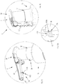
- Figures 1 and 2 show the dispensing device made according to a first preferred embodiment of the invention and identified by the reference numeral 1.
- the dispensing device according to the invention is shown as a part of a dispensing system comprising also a container C, to which it is applied.
- the dispensing device 1 substantially comprises an engagement portion 10, for example a threaded metal ring, through which the device 1 can be fixed to the container C, preferably screwed to the neck of the container C holding the fluid or liquid to be dispensed, drawing and dispensing means 20, as well as a main operating body 30, or operating cap 30, and finally a dispensing nozzle 40 suited to dispense the fluid or liquid towards the outside.
- an engagement portion 10 for example a threaded metal ring, through which the device 1 can be fixed to the container C, preferably screwed to the neck of the container C holding the fluid or liquid to be dispensed, drawing and dispensing means 20, as well as a main operating body 30, or operating cap 30, and finally a dispensing nozzle 40 suited to dispense the fluid or liquid towards the outside.
- the parts that make up the dispensing device 1 are preferably made of a plastic material, for example through a thermoplastic moulding process.
- elastic return means 25, preferably constituted by a helical spring, allow the cap 30 to be brought back to its initial position, or rest position, ready for a new dispensing cycle.
- the engagement portion 10 has a substantially tubular shape, so that it can accommodate the cap 30 during its sliding movement, as explained above.
- the engagement portion 10 preferably comprises an edge 12 which delimits the upper part of the engagement portion 10.
- the nozzle 40 is preferably of the type that can be switched, in particular rotated, between a dispensing position, represented for example in Figures 3 , 6 , 8 and 10 , and a non-dispensing position, represented for example in Figures 5 , 7 , 9 and 12 .
- a dispensing position represented for example in Figures 3 , 6 , 8 and 10
- a non-dispensing position represented for example in Figures 5 , 7 , 9 and 12 .
- the dispensing duct 41 In the dispensing position the dispensing duct 41 is in communication with the inside of the operating cap 30 (see, in particular, Figure 8A ), while, on the contrary, in the non-dispensing position ( Figure 9A ) the dispensing duct 41 is not in communication with the inside of the cap 30, and the nozzle 40 closes the cap 30, thus interrupting any communication between the space inside the cap 30 (and thus inside the device 1) and the outside.
- substantially the nozzle 40 is first switched from the non-dispensing position ( Figure 5 ) to the dispensing position ( Figure 3 ), successively the cap 30 is pressed (once or several times, according to known methods) and the fluid or liquid is dispensed ( Figure 4 ) and finally the nozzle 40 is switched again from the dispensing position to the non-dispensing position, if required.
- the nozzle 40 comprises a constraining portion 114 housed in a housing or constraint seat 115 having a corresponding shape and defined by the operating cap 30.
- the shape of the constraining portion 114 and of the matching seat 115 can be selected according to the needs and/or circumstances; for example, a constraining portion 114 in a substantially cylindrical or even substantially spherical shape can be provided, wherein the shape of the seat 115 will match the shape of the constraining portion 114.
- the device 1 comprises constraining means 50 suited to prevent any mutual movement of the operating cap 30 and the engagement portion 10 when the dispensing nozzle 40 is arranged in the non-dispensing position.
- the constraining means 50 preferably comprise a first counteracting element 52 associated with the dispensing nozzle 40 and a second counteracting element 14 associated with the engagement portion 10.
- the first counteracting element comprises a projecting element 52 that protrudes from the dispensing nozzle 40 and the second counteracting element comprises a counteracting portion 14 of the upper edge 12 of the engagement portion 10.
- the projecting element 52 When the dispensing nozzle 40 is arranged in the non-dispensing position, the projecting element 52 abuts against the counteracting portion 14 of the upper edge 12 of the engagement portion 10, as shown in particular in Figure 12A .
- the mutual position of the projecting element 52 and the counteracting portion 14 preferably prevents the movement of the operating cap 30 with respect to the engagement portion 10 in the case where the operating cap 30 is pressed along the pressing direction P.
- the projecting element 52 is preferably constituted by a tab that projects from the dispensing nozzle 40 in the direction of the engagement portion 10 when the same dispensing nozzle 40 is in its non-dispensing position.
- the operating cap 30 comprises a housing seat 32 suited to house the free end 52a of the tab 52.
- the housing seat 32 allows the dispensing nozzle 40 to be positioned in such a way that it is as adherent as possible to the engagement portion 10 when the same dispensing nozzle 40 is in its non-dispensing position, with evident advantages in terms of limitation of the overall dimensions of the device 1 itself.
- said housing seat may be absent.
- the projecting element 52 preferably comprises also a reference portion 54 that protrudes from the projecting element 52 in the direction of the counteracting portion 14 of the upper edge 12 of the engagement portion 10 when the dispensing nozzle 40 is in its non-dispensing position.
- the reference portion 54 allows the snap-on connection of the projecting element 52 with the upper edge 12 of the engagement portion 10.
- the snap-on connection of the projecting element 52 is preferably obtained thanks to the elasticity of the projecting element 52, such elasticity being due to the material with which the projecting element 52 is made.
- the projecting element 52 is preferably made of a plastic material.
- the projecting element 52 and the dispensing nozzle 40 are preferably obtained in a single piece, for example through a thermoplastic moulding process.
- the elasticity of the projecting element 52 allows the reference portion 54 to overlap the counteracting portion 14 of the upper edge 12 of the engagement portion 10 when the nozzle 40 is brought/rotated to the non-dispensing position by exerting a sufficiently high force, and the projecting element 52 to be successively maintained in the locked position.
- the elasticity of the projecting element 52 allows the reference portion 54 to overlap the counteracting portion 14 of the upper edge 12 of the engagement portion 10 when the nozzle 40 is brought/rotated to the dispensing position only if a sufficiently high force is applied.
- the snap-on connection of the projecting element 52 further guarantees that the dispensing nozzle 40 is maintained in its non-dispensing position in a stable manner, avoiding undesired outflows of fluid or liquid from the container C.
- the snap-on connection of the projecting element 52 to the upper edge 12 of the engagement portion 10 furthermore prevents any movement of the dispensing nozzle 40 towards the dispensing position.
- the snap-on connection may be obtained between the dispensing nozzle and the operating cap, for example the tab may snap in a corresponding slot made in the operating cap.
- Figures 13, 14 and 14A show a preferred variant embodiment of the invention, as already explained above.
- Said variant embodiment differs from the embodiment previously illustrated and described with reference to Figures from 1 to 12A in that the engagement portion 10 has no housing seat for the projecting element 152.
- the projecting element 152 is shorter than the projecting element 52 previously described and its free end 152a preferably abuts on the counteracting portion 14 of the upper edge 12 of the engagement portion 10.
- the projecting element 152 is preferably made of a plastic material and is preferably made in a single piece with the dispensing nozzle 40.
- Figures 15, 16 and 16A show a preferred variant embodiment of the invention, which differs from the embodiment previously illustrated above and described with reference to Figures from 1 to 12A in that the housing seat 232 of the engagement portion 10 which houses the end 52a of the projecting element 52 is constituted by a portion of an annular recess 231 that is located on the entire circumference of the engagement portion 10.
- the end 52a of the projecting element 52 will be certainly accommodated in the housing seat 232, since the latter is present on the entire circumference, independently of the mutual position of the operating cap 30 and the dispensing nozzle 40 with respect to the engagement portion 10.
- Figures 17, 18 and 18A show a preferred variant embodiment of the invention, which differs from the embodiment previously illustrated above and described with reference to Figures from 1 to 12A in that the second counteracting element 314 comprises an element that projects from the engagement portion 10.
- the mutual position of the projecting elements 52, 314 prevents any movement of the operating cap 30 with respect to the engagement portion 10 in the case where the operating cap 30 is pressed along the pressing direction P.
- the operating cap 30 is pressed, on purpose or inadvertently, along the pressing direction P when the dispensing nozzle 40 is in its non-dispensing position, undesired outflows if fluid or liquid from the container C are avoided.
- the projecting element 314 of the engagement portion 10 preferably comprises also a reference portion 354 which protrudes from the projecting element 314 in the direction of the projecting element 52 of the dispensing nozzle 40.
- the reference portions 54, 354 of the respective projecting elements 52, 314 allow the mutual snap-on connection of the projecting elements 52, 314.
- the snap-on connection of the projecting elements 52, 314 is preferably obtained thanks to the elasticity of the projecting elements 52, 314, such elasticity being due to the material with which the projecting elements 52, 314 are made.
- the projecting element 314 of the engagement portion 10 is made of a plastic material.
- the projecting element 314 and the engagement portion 10 are preferably obtained in a single piece, for example through a thermoplastic moulding process.
- Figures 19, 20 and 20A show a preferred variant embodiment of the invention, which differs from the embodiment previously illustrated above and described with reference to Figures 17, 18 and 18A in that the first counteracting element 452 comprises a seat which is associated with the dispensing nozzle 40.
- the seat 452 preferably comprises a slot 452a defined in a projection that protrudes from the dispensing nozzle 40 in the direction of the projecting element 314 of the engagement portion 10.
- the projecting element 314 of the engagement portion 10 fits, preferably snaps into the seat 452 that defines the first counteracting element, more particularly in the slot 452a, as shown in the detail of Figure 20A .
- the mutual position of the projecting element 314 inside the seat 452 prevents any movement of the operating cap 30 with respect to the engagement portion 10 in the case where the operating cap 30 is pressed along the pressing direction P.
- the operating cap 30 is pressed, on purpose or inadvertently, along the pressing direction P when the dispensing nozzle 40 is in its non-dispensing position, undesired outflows of fluid or liquid from the container C are avoided.
- the present invention makes it possible to achieve all the set objects and to overcome the drawbacks posed by the dispensing devices made according to the known art.
- the present invention in fact, makes it possible to eliminate or at least minimize the risk of liquid or fluid leakages when the nozzle is in its non-dispensing position.
- the objects of the invention can be achieved through the constraining means, which interact in order to prevent any movement of the main operating body with respect to the engagement portion along the pressing direction when the dispensing nozzle is in the non-dispensing position, as defined in claim 1.
Landscapes
- Chemical & Material Sciences (AREA)
- Dispersion Chemistry (AREA)
- Engineering & Computer Science (AREA)
- Mechanical Engineering (AREA)
- Closures For Containers (AREA)
- Containers And Packaging Bodies Having A Special Means To Remove Contents (AREA)
- Physical Or Chemical Processes And Apparatus (AREA)
Description
- The present invention concerns the dispensing of fluids or liquids. In particular, the present invention concerns the dispensing of fluids or liquids such as, for example, detergents, soaps, creams, for example for body and hair care, for washing one's hands, etc. In greater detail, the present invention concerns a dispensing device suited to dispense fluids or liquids of the type described above.
- In even greater detail, the present invention concerns a dispensing device of the type suited to be coupled with a container suited to hold the fluid or liquid to be dispensed, for example suited to be fixed to the neck of a container in the shape of a bottle or a similar shape.
- Dispensing devices for dispensing liquids or fluids, for example liquid or fluid soaps for personal care are known in the art and widely marketed and used, said devices being suited, in fact, to allow liquids or fluids held in a container to be dispensed. Said devices generally comprise engagement means (for example, a threaded ring) suited to allow them to be applied or fixed to a container (for example, to the neck of a bottle-shaped container), drawing and dispensing means suited to draw the liquid or fluid from the container and to successively dispense it towards the outside, as well as operating means suited to operate the drawing and dispensing means, as well as, finally, a nozzle or spout through which the liquid or fluid is actually dispensed.
- With the dispensing device applied to the container, for example, as mentioned above, screwed to the neck of the container, the drawing pipe of the drawing and dispensing means is at least partially immersed in the liquid or fluid to be dispensed, while the operating means and the dispensing nozzle are positioned outside the container itself. Exerting a pressure on the operating means, for example with the palm of a hand, makes the fluid or liquid flow upwards along the drawing means and allows it to be dispensed towards the outside through the dispensing nozzle.
- In the most common and simple dispensing means, the dispensing nozzle, rigidly fixed to the operating means or even made in a single piece with the operating means, projects from the operating means and thus represents a hindrance which considerably complicates the handling of the device, both when it is handled individually and when it is handled together with the container (when it is applied to the container itself).
- For example, a projecting dispensing nozzle makes the packaging operations considerably difficult. Furthermore, a projecting nozzle is a critical part, as it is likely to be damaged or even broken, both during the packaging operations and successively during transport, shipment, or handling in general.
- In the attempt to overcome, at least partially, the drawbacks summed up above, dispensing devices have been recently proposed which are provided with a dispensing nozzle that can be switched from a non-dispensing position to a use or dispensing position, wherein in the non-dispensing position the dispensing nozzle occupies a minimum space or in any case less space than in the dispensing position. For example, devices have been proposed in which, in the dispensing position, the dispensing nozzle extends along a direction that is substantially perpendicular to the direction of extension of the drawing pipe (which corresponds to a direction substantially parallel to the plane where the container rests), while in the non-dispensing position the dispensing nozzle extends along a direction that is substantially parallel to the drawing pipe (and thus substantially along a vertical with respect to the plane where the container rests).
- However, the dispensing devices with switching dispensing nozzle are not without drawbacks or disadvantages, either.
- For example, a first drawback or inconvenience derives from the risk of undesired leakages of fluid or liquid in the case where the operating means that operate the drawing and dispensing means are activated, on purpose or inadvertently, when the dispensing nozzle is in the non-dispensing position.
- A further drawback is related to the instability of the dispensing nozzle when it is in the non-dispensing position and to the fact that it can be moved, which makes it difficult to handle, for example during the packaging operations, and even to the risk of the nozzle being undesirably switched to its dispensing position. Therefore, it is one object of the present invention to overcome the drawbacks mentioned above and observed in the solutions known in the art.
- In particular, the objects of the present invention can be summed up as follows.
- It is a first object of the present invention to provide a dispensing device suited to dispense fluids or liquids of the type with switching dispensing nozzle which makes it possible to prevent fluid or liquid leakages when the nozzle is in its non-dispensing position.
- Among the objects of the present invention there is also the object to provide a dispensing device for fluids or liquids of the type with switching dispensing nozzle which makes the nozzle as stable as possible when it is in its non-dispensing position.
- Dispensing devices according to the prior art are known from
documents EP 1 116 522 A2 ,WO 01/91911 A1 US 3,221,950 ,US 4,272,228 ,JP H10236503 US 3,907,174 . - The present invention originates from the general consideration according to which the drawbacks observed in the devices made according to the known art can be overcome or at least minimized by conveniently shaping the dispensing nozzle in such a way as to fix it in a stable manner in its non-dispensing position.
- Accordingly, a dispensing device is provided in accordance with
claim 1. - Preferably, the second counteracting element comprises a projecting element associated with the engagement portion or a housing seat associated with the engagement portion or a counteracting portion of an edge of the engagement portion.
- In a preferred embodiment, the device furthermore comprises snap-on connection means suited to carry out a snap-on connection between the first counteracting element and the second counteracting element.
- According to a preferred embodiment, the second counteracting element comprises a tab which projects from the engagement portion.
- Preferably, said projecting tab is at least partially elastic.
- In a preferred embodiment, the projecting element of the first counteracting element and/or of the second counteracting element comprises a reference portion which protrudes from the projecting element and is suited to become engaged with a surface of the second counteracting element and/or of the first counteracting element when the dispensing nozzle is in the non-dispensing position.
- According to a preferred embodiment, the engagement portion comprises at least one recessed seat suited to at least partially accommodate an end portion of the first counteracting element.
- Preferably, the main operating body comprises an operating cover and the engagement portion comprises a threaded metal ring suited to accommodate the operating cover, said operating cover being suited to slide with respect to the threaded metal ring, preferably to slide inside the threaded metal ring, between the rest position and the activating position and vice versa.
- According to a preferred embodiment, the device comprises elastic return means suited to bring the main operating body back to the rest position from the activating position.
- The subject of the present invention includes also a system for dispensing a fluid or a liquid, said system comprising a container suited to hold said fluid or liquid and a dispensing device made according to one or more of the variant embodiments summed up above and/or described below.
- Further advantages, objects and characteristics, as well as further embodiments of the present invention, are defined in the claims and are illustrated in the following description, with reference to the attached drawings; in the drawings, corresponding and/or equivalent characteristics and/or component parts of the present invention are identified by the same reference numbers. In particular, in the figures:
-
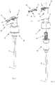
Figure 1 shows an axonometric view of a dispensing device made according to an embodiment of the present invention, with the dispensing nozzle in the dispensing position; -
Figure 2 shows an exploded view ofFigure 1 ; -
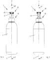
Figure 3 shows a system in which the dispensing device ofFigure 1 is applied to a container in a first operating position; -
Figure 4 shows the system ofFigure 3 with the dispensing device activated for the dispensing operation; -
Figure 5 shows the system ofFigure 3 with the dispensing device with the dispensing nozzle in the non-dispensing position; -
Figure 6 shows a side view of the dispensing device ofFigure 3 ; -
Figure 7 shows a side view of the dispensing device ofFigure 5 with the dispensing nozzle in the non-dispensing position; -
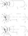
Figure 8 shows a sectional view of the system ofFigure 6 according to section plane VIII-VIII; -
Figure 8A shows an enlarged detail ofFigure 8 ; -
Figure 9 shows a sectional view of the system ofFigure 7 according to the section plane IX-IX; -
Figure 9A shows an enlarged detail ofFigure 9 ; -
Figure 10 shows an axonometric view of a detail of the system ofFigure 3 with the dispensing nozzle in the dispensing position; -
Figure 11 shows the detail of the system ofFigure 10 with the dispensing nozzle in an intermediate position between the dispensing position and a non-dispensing position; -
Figure 12 shows a detail of the system ofFigure 5 with the dispensing nozzle in a non-dispensing position; -
Figure 12A shows a sectional view of a detail ofFigure 12 ; -
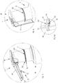
Figure 13 shows a variant embodiment ofFigure 10 ; -
Figure 14 shows the detail of the system ofFigure 13 with the dispensing nozzle in a non-dispensing position; -
Figure 14A shows a sectional view of a detail ofFigure 14 ; -
Figure 15 shows a variant embodiment ofFigure 10 ; -
Figure 16 shows the detail of the system ofFigure 15 with the dispensing nozzle in a non-dispensing position; -
Figure 16A shows an enlarged detail ofFigure 16 ; -
Figure 17 shows a variant embodiment ofFigure 10 ; -
Figure 18 shows the detail of the system ofFigure 17 with the dispensing nozzle in a non-dispensing position; -
Figure 18A shows an enlarged detail ofFigure 18 ; -
Figure 19 shows a variant embodiment ofFigure 10 ; -
Figure 20 shows the detail of the system ofFigure 19 with the dispensing nozzle in a non-dispensing position; -
Figure 20A shows an enlarged detail ofFigure 20 . - Even though the present invention is described below with reference to its embodiments illustrated in the drawings, the present invention is not limited to the embodiments illustrated in the drawings and described in detail here below. On the contrary, the scope of the present invention covers all those variants of the embodiments illustrated in the drawings and described in detail here below which appear to be obvious to the expert in the art.
-
Figures 1 and 2 show the dispensing device made according to a first preferred embodiment of the invention and identified by thereference numeral 1. - In the other figures and with regard to the other preferred embodiments described below, the dispensing device according to the invention is shown as a part of a dispensing system comprising also a container C, to which it is applied.
- The
dispensing device 1 substantially comprises anengagement portion 10, for example a threaded metal ring, through which thedevice 1 can be fixed to the container C, preferably screwed to the neck of the container C holding the fluid or liquid to be dispensed, drawing and dispensing means 20, as well as amain operating body 30, or operatingcap 30, and finally a dispensingnozzle 40 suited to dispense the fluid or liquid towards the outside. - The parts that make up the
dispensing device 1 are preferably made of a plastic material, for example through a thermoplastic moulding process. - Pressing the
operating cap 30, for example with the palm of a hand along a pressing direction P, as shown inFigure 4 , makes the fluid or liquid flow upwards along the suction pipe 15 (at least partially immersed in the fluid or liquid) of the drawing and dispensing means 20, and thus along the same means 20, and results in the fluid or liquid being dispensed through thecap 30 towards the outside, in particular through the dispensingduct 41 of thenozzle 40. - While the
operating cap 30 is pressed along the pressing direction P, thesame cap 30 slides inside theengagement portion 10 along a main sliding direction X substantially parallel to the pressing direction P, so as to operate said drawing and dispensing means 20, as explained above. - After the dispensing operation, elastic return means 25, preferably constituted by a helical spring, allow the
cap 30 to be brought back to its initial position, or rest position, ready for a new dispensing cycle. - The
engagement portion 10 has a substantially tubular shape, so that it can accommodate thecap 30 during its sliding movement, as explained above. Theengagement portion 10 preferably comprises anedge 12 which delimits the upper part of theengagement portion 10. - The operating modes of the drawing and dispensing means 20, in particular the mechanisms through which the fluid or liquid flows upwards through the
means 20 and successively flows out through theduct 41 of thenozzle 40, are not necessarily included in the objects of the present invention, therefore a detailed description of the same is omitted for the sake of brevity. - According to an aspect of the present invention, the
nozzle 40 is preferably of the type that can be switched, in particular rotated, between a dispensing position, represented for example inFigures 3 ,6 ,8 and10 , and a non-dispensing position, represented for example inFigures 5 ,7 ,9 and12 . In the dispensing position the dispensingduct 41 is in communication with the inside of the operating cap 30 (see, in particular,Figure 8A ), while, on the contrary, in the non-dispensing position (Figure 9A ) the dispensingduct 41 is not in communication with the inside of thecap 30, and thenozzle 40 closes thecap 30, thus interrupting any communication between the space inside the cap 30 (and thus inside the device 1) and the outside. - According to the methods adopted for use and operation of the
device 1, substantially thenozzle 40 is first switched from the non-dispensing position (Figure 5 ) to the dispensing position (Figure 3 ), successively thecap 30 is pressed (once or several times, according to known methods) and the fluid or liquid is dispensed (Figure 4 ) and finally thenozzle 40 is switched again from the dispensing position to the non-dispensing position, if required. - Preferably, the
nozzle 40 comprises a constrainingportion 114 housed in a housing orconstraint seat 115 having a corresponding shape and defined by theoperating cap 30. The shape of the constrainingportion 114 and of thematching seat 115 can be selected according to the needs and/or circumstances; for example, a constrainingportion 114 in a substantially cylindrical or even substantially spherical shape can be provided, wherein the shape of theseat 115 will match the shape of the constrainingportion 114. - According to a preferred aspect of the present invention, the
device 1 comprises constraining means 50 suited to prevent any mutual movement of theoperating cap 30 and theengagement portion 10 when the dispensingnozzle 40 is arranged in the non-dispensing position. - The constraining means 50 preferably comprise a
first counteracting element 52 associated with the dispensingnozzle 40 and asecond counteracting element 14 associated with theengagement portion 10. - In the first preferred embodiment carried out according to the present invention, as illustrated in particular in Figures from 10 to 12A, the first counteracting element comprises a projecting
element 52 that protrudes from the dispensingnozzle 40 and the second counteracting element comprises a counteractingportion 14 of theupper edge 12 of theengagement portion 10. - When the dispensing
nozzle 40 is arranged in the non-dispensing position, the projectingelement 52 abuts against the counteractingportion 14 of theupper edge 12 of theengagement portion 10, as shown in particular inFigure 12A . The mutual position of the projectingelement 52 and the counteractingportion 14 preferably prevents the movement of theoperating cap 30 with respect to theengagement portion 10 in the case where theoperating cap 30 is pressed along the pressing direction P. - Advantageously, if the
operating cap 30 is pressed, on purpose or inadvertently, along the pressing direction P when the dispensingnozzle 40 is in its non-dispensing position, undesired outflows of fluid or liquid from the container C are avoided. - The projecting
element 52 is preferably constituted by a tab that projects from the dispensingnozzle 40 in the direction of theengagement portion 10 when thesame dispensing nozzle 40 is in its non-dispensing position. - Preferably, the
operating cap 30 comprises ahousing seat 32 suited to house thefree end 52a of thetab 52. - Advantageously, the
housing seat 32 allows the dispensingnozzle 40 to be positioned in such a way that it is as adherent as possible to theengagement portion 10 when thesame dispensing nozzle 40 is in its non-dispensing position, with evident advantages in terms of limitation of the overall dimensions of thedevice 1 itself. - In variant embodiments, as illustrated for example in
Figures 13, 14 and 14A , said housing seat may be absent. - According to the preferred embodiment illustrated herein, the projecting
element 52 preferably comprises also areference portion 54 that protrudes from the projectingelement 52 in the direction of the counteractingportion 14 of theupper edge 12 of theengagement portion 10 when the dispensingnozzle 40 is in its non-dispensing position. - The
reference portion 54 allows the snap-on connection of the projectingelement 52 with theupper edge 12 of theengagement portion 10. - The snap-on connection of the projecting
element 52 is preferably obtained thanks to the elasticity of the projectingelement 52, such elasticity being due to the material with which the projectingelement 52 is made. The projectingelement 52 is preferably made of a plastic material. The projectingelement 52 and the dispensingnozzle 40 are preferably obtained in a single piece, for example through a thermoplastic moulding process. - The elasticity of the projecting
element 52 allows thereference portion 54 to overlap the counteractingportion 14 of theupper edge 12 of theengagement portion 10 when thenozzle 40 is brought/rotated to the non-dispensing position by exerting a sufficiently high force, and the projectingelement 52 to be successively maintained in the locked position. - Analogously, the elasticity of the projecting
element 52 allows thereference portion 54 to overlap the counteractingportion 14 of theupper edge 12 of theengagement portion 10 when thenozzle 40 is brought/rotated to the dispensing position only if a sufficiently high force is applied. - Advantageously, the snap-on connection of the projecting
element 52 further guarantees that the dispensingnozzle 40 is maintained in its non-dispensing position in a stable manner, avoiding undesired outflows of fluid or liquid from the container C. - Advantageously, the snap-on connection of the projecting
element 52 to theupper edge 12 of theengagement portion 10 furthermore prevents any movement of the dispensingnozzle 40 towards the dispensing position. - In a preferred variant embodiment, not illustrated herein, the snap-on connection may be obtained between the dispensing nozzle and the operating cap, for example the tab may snap in a corresponding slot made in the operating cap.
-
Figures 13, 14 and 14A show a preferred variant embodiment of the invention, as already explained above. - Said variant embodiment differs from the embodiment previously illustrated and described with reference to Figures from 1 to 12A in that the
engagement portion 10 has no housing seat for the projectingelement 152. - Furthermore, preferably, the projecting
element 152 is shorter than the projectingelement 52 previously described and itsfree end 152a preferably abuts on the counteractingportion 14 of theupper edge 12 of theengagement portion 10. The projectingelement 152 is preferably made of a plastic material and is preferably made in a single piece with the dispensingnozzle 40. Advantageously, if theoperating cap 30 is pressed, on purpose or inadvertently, along the pressing direction P when the dispensingnozzle 40 is in its non-dispensing position, undesired outflows of fluid or liquid from the container C are avoided. -
Figures 15, 16 and 16A show a preferred variant embodiment of the invention, which differs from the embodiment previously illustrated above and described with reference to Figures from 1 to 12A in that thehousing seat 232 of theengagement portion 10 which houses theend 52a of the projectingelement 52 is constituted by a portion of anannular recess 231 that is located on the entire circumference of theengagement portion 10. - Advantageously, when the
nozzle 40 is brought/rotated to the non-dispensing position, theend 52a of the projectingelement 52 will be certainly accommodated in thehousing seat 232, since the latter is present on the entire circumference, independently of the mutual position of theoperating cap 30 and the dispensingnozzle 40 with respect to theengagement portion 10. - This solution makes it possible to obtain all the advantages mentioned with reference to the previous embodiments.
-
Figures 17, 18 and 18A show a preferred variant embodiment of the invention, which differs from the embodiment previously illustrated above and described with reference to Figures from 1 to 12A in that thesecond counteracting element 314 comprises an element that projects from theengagement portion 10. - When the dispensing
nozzle 40 is arranged in the non-dispensing position, the projectingelement 52 of the dispensingnozzle 40 abuts against and on the projectingelement 314 of theengagement portion 10, as shown in the detail ofFigure 18A . - The mutual position of the projecting
elements operating cap 30 with respect to theengagement portion 10 in the case where theoperating cap 30 is pressed along the pressing direction P. Advantageously, if theoperating cap 30 is pressed, on purpose or inadvertently, along the pressing direction P when the dispensingnozzle 40 is in its non-dispensing position, undesired outflows if fluid or liquid from the container C are avoided. - The projecting
element 314 of theengagement portion 10 preferably comprises also areference portion 354 which protrudes from the projectingelement 314 in the direction of the projectingelement 52 of the dispensingnozzle 40. - The
reference portions elements elements - The snap-on connection of the projecting
elements elements elements element 314 of theengagement portion 10 is made of a plastic material. The projectingelement 314 and theengagement portion 10 are preferably obtained in a single piece, for example through a thermoplastic moulding process. - This solution makes it possible to achieve all the advantages mentioned with reference to the previous embodiments.
-
Figures 19, 20 and 20A show a preferred variant embodiment of the invention, which differs from the embodiment previously illustrated above and described with reference toFigures 17, 18 and 18A in that thefirst counteracting element 452 comprises a seat which is associated with the dispensingnozzle 40. - The
seat 452 preferably comprises aslot 452a defined in a projection that protrudes from the dispensingnozzle 40 in the direction of the projectingelement 314 of theengagement portion 10. - When the dispensing
nozzle 40 is in the non-dispensing position, the projectingelement 314 of theengagement portion 10 fits, preferably snaps into theseat 452 that defines the first counteracting element, more particularly in theslot 452a, as shown in the detail ofFigure 20A . - The mutual position of the projecting
element 314 inside theseat 452 prevents any movement of theoperating cap 30 with respect to theengagement portion 10 in the case where theoperating cap 30 is pressed along the pressing direction P. Advantageously, if theoperating cap 30 is pressed, on purpose or inadvertently, along the pressing direction P when the dispensingnozzle 40 is in its non-dispensing position, undesired outflows of fluid or liquid from the container C are avoided. - This solution makes it possible to achieve all the advantages mentioned with reference to the previous embodiments.
- It has thus been shown, by means of the preceding detailed description of the embodiments of the present invention illustrated in the drawings, that the present invention makes it possible to achieve all the set objects and to overcome the drawbacks posed by the dispensing devices made according to the known art. The present invention, in fact, makes it possible to eliminate or at least minimize the risk of liquid or fluid leakages when the nozzle is in its non-dispensing position.
- In particular, it has been shown that the objects of the invention can be achieved through the constraining means, which interact in order to prevent any movement of the main operating body with respect to the engagement portion along the pressing direction when the dispensing nozzle is in the non-dispensing position, as defined in
claim 1. - While the present invention has been described with reference to the specific embodiments represented in the drawings, it should be pointed out that the present invention is not limited to the particular embodiments illustrated and described; on the contrary, further variants of the embodiments described herein fall within the scope of the present invention, which is defined in the claims.
Claims (10)
- Dispensing device (1) suited to dispense a liquid or a fluid held in a container (C), said device (1) comprising
an engagement portion (10) for the mutual engagement of said device (1) and said container (C),
drawing and dispensing means (20) suited to draw said fluid or liquid from said container (C) and to respectively dispense it,
a main operating body (30) suited to operate said device (1) through pressure exerted along a pressing direction (P) of said drawing and dispensing means (20), said main operating body (30) being suited to be moved with respect to said engagement portion (10), when subjected to said pressure, between a rest position and an activating position for the operation of said drawing and dispensing means (20), as well as
a dispensing nozzle (40) fixed to said main operating body (30) and provided with a dispensing duct (41) for dispensing said fluid or liquid, wherein said dispensing nozzle (40) can be switched with respect to said main operating body (30), through a rotary movement, between a dispensing position, in which said dispensing duct (41) is in communication with the inside of said main operating body (30), and a non-dispensing position, and
constraining means (50) suited to prevent the movement of said main operating body (30) along said pressing direction (P) with respect to said engagement portion (10) when said dispensing nozzle (40) is in the non-dispensing position,
wherein said constraining means (50) comprise a first counteracting element (52; 152; 452) associated with said dispensing nozzle (40) and a second counteracting element (14; 314) associated with said engagement portion (10),
characterized in that
said first counteracting element (52; 152) comprises a tab that protrudes from said dispensing nozzle (40), and in that
said main operating body (30) is configured to slide inside said engagement portion (10). - Device (1) according to claim 1, characterized in that said second counteracting element (314) comprises a projecting element associated with said engagement portion (10) or a housing seat associated with said engagement portion (10) or a counteracting portion (14) of an edge (12) of said engagement portion (10).
- Device (1) according to claim 1 or 2, characterized in that it comprises, furthermore, snap-on connection means suited to provide a snap-on connection between said first counteracting element (52; 152; 452) and said second counteracting element (14; 314).
- Device (1) according to any of the claims from 1 to 3, characterized in that said second counteracting element (314) comprises a tab that protrudes from said engagement portion (10).
- Device (1) according to claim 3 or 4, characterized in that said projecting tab (52; 152; 314) is at least partially elastic.
- Device (1) according to any of the claims from 2 to 5, characterized in that said tab of said first counteracting element (52; 152) and/or said projecting element of said second counteracting element (314) comprises a reference portion (54; 354) that protrudes from said tab suited to become engaged in a surface of said second counteracting element and/or of said first counteracting element when said dispensing nozzle (40) is in said non-dispensing position.
- Device (1) according to any of the claims from 1 to 6, characterized in that said engagement portion (10) comprises at least one recessed seat (32; 232) suited to at least partially accommodate an end portion (52a; 452a) of said first counteracting element (52; 452).
- Device (1) according to any of the preceding claims, characterized in that said main operating body (30) comprises an operating cover and said engagement portion (10) comprises a threaded metal ring suited to receive said operating cover, said operating cover being suited to slide with respect to said threaded metal ring, preferably to slide inside said threaded metal ring, between said rest position and said activating position and vice versa.
- Device (1) according to any of the preceding claims, characterized in that it comprises elastic return means (25) suited to bring said main operating body (30) back to said rest position from said activating position.
- System for dispensing a fluid or a liquid, said system comprising a container (C) suited to hold said fluid or liquid, characterized in that said system furthermore comprises a device (1) according to any of the claims from 1 to 9.
Applications Claiming Priority (2)
| Application Number | Priority Date | Filing Date | Title |
|---|---|---|---|
| IT102016000123591A IT201600123591A1 (en) | 2016-12-06 | 2016-12-06 | DISTRIBUTION DEVICE FOR THE DISTRIBUTION OF LIQUIDS OR FLUIDS IN GENERAL. |
| PCT/IB2017/057406 WO2018104821A1 (en) | 2016-12-06 | 2017-11-27 | Dispensing device for dispensing liquids or fluids |
Publications (2)
| Publication Number | Publication Date |
|---|---|
| EP3551344A1 EP3551344A1 (en) | 2019-10-16 |
| EP3551344B1 true EP3551344B1 (en) | 2021-01-06 |
Family
ID=58402059
Family Applications (1)
| Application Number | Title | Priority Date | Filing Date |
|---|---|---|---|
| EP17809044.5A Active EP3551344B1 (en) | 2016-12-06 | 2017-11-27 | Dispensing device for dispensing liquids or fluids |
Country Status (6)
| Country | Link |
|---|---|
| US (1) | US10751741B2 (en) |
| EP (1) | EP3551344B1 (en) |
| CN (1) | CN110062666B (en) |
| BR (1) | BR112019011204A2 (en) |
| IT (1) | IT201600123591A1 (en) |
| WO (1) | WO2018104821A1 (en) |
Families Citing this family (4)
| Publication number | Priority date | Publication date | Assignee | Title |
|---|---|---|---|---|
| WO2018140720A1 (en) | 2017-01-30 | 2018-08-02 | Silgan Dispensing Systems Corporation | Sprayers, dispensers, and methods for using the same |
| EP3846943B1 (en) * | 2018-09-06 | 2024-11-13 | Taplast S.R.L. | Device for dispensing fluids or liquids in general and system using this device |
| CN110817111A (en) * | 2019-10-25 | 2020-02-21 | 浙江正庄实业有限公司 | Environment-friendly high-rigidity duckbill folding type emulsion pump and preparation method thereof |
| CN114261641A (en) * | 2021-11-22 | 2022-04-01 | 黑武士2K气雾剂有限公司 | Push Releases and Aerosol Cans for Aerosol Cans |
Family Cites Families (16)
| Publication number | Priority date | Publication date | Assignee | Title |
|---|---|---|---|---|
| US3221950A (en) * | 1963-10-09 | 1965-12-07 | Valve Corp Of America | Aerosol dispenser |
| US3907174A (en) * | 1971-04-13 | 1975-09-23 | Vca Corp | Dispensing pump construction with foldable discharge nozzle |
| US3874562A (en) * | 1972-11-10 | 1975-04-01 | Polytop Corp | Dispensing closure with pump parts and container using the same |
| US4272228A (en) * | 1979-04-11 | 1981-06-09 | Security Plastics, Inc. | High volume dispensing pump |
| GB8620072D0 (en) * | 1986-08-18 | 1986-10-01 | English Glass Co Ltd | Dispenser |
| US4901878A (en) * | 1987-03-16 | 1990-02-20 | S.A.Y. Industries, Inc. | Rigid fluid container |
| US5392968A (en) * | 1993-06-14 | 1995-02-28 | Dark; Richard C. G. | Dispensing closure and method |
| DE4438375A1 (en) | 1994-10-27 | 1996-05-02 | Pfeiffer Erich Gmbh & Co Kg | Discharge device for media |
| JPH10236503A (en) * | 1997-02-26 | 1998-09-08 | Yoshino Kogyosho Co Ltd | Liquid ejection pump |
| US5890628A (en) * | 1997-03-18 | 1999-04-06 | Outer Circle Products, Ltd. | Dispensing lid assembly for a container |
| IT1315351B1 (en) * | 2000-05-26 | 2003-02-10 | Taplast Spa | BELLOW PUMP FOR THE DISTRIBUTION OF LIQUIDS |
| CN2461883Y (en) * | 2001-02-16 | 2001-11-28 | 胜丰祥股份有限公司 | Liquid container pump head device with outer spring |
| CN101583544A (en) * | 2007-01-16 | 2009-11-18 | 李英柱 | Pumping device with collapsible nozzle |
| US8616419B2 (en) * | 2010-07-21 | 2013-12-31 | Martin Slack | Reusable containers |
| WO2014033495A1 (en) * | 2012-08-30 | 2014-03-06 | Zhejiang JM Industry Co., Ltd | Powder dispenser |
| US9352896B2 (en) * | 2013-03-14 | 2016-05-31 | Berry Plastics Corporation | Dispenser apparatus |
-
2016
- 2016-12-06 IT IT102016000123591A patent/IT201600123591A1/en unknown
-
2017
- 2017-11-27 EP EP17809044.5A patent/EP3551344B1/en active Active
- 2017-11-27 CN CN201780075613.3A patent/CN110062666B/en active Active
- 2017-11-27 US US16/467,114 patent/US10751741B2/en active Active
- 2017-11-27 WO PCT/IB2017/057406 patent/WO2018104821A1/en not_active Ceased
- 2017-11-27 BR BR112019011204-9A patent/BR112019011204A2/en not_active Application Discontinuation
Non-Patent Citations (1)
| Title |
|---|
| None * |
Also Published As
| Publication number | Publication date |
|---|---|
| CN110062666A (en) | 2019-07-26 |
| WO2018104821A1 (en) | 2018-06-14 |
| US20190314841A1 (en) | 2019-10-17 |
| EP3551344A1 (en) | 2019-10-16 |
| IT201600123591A1 (en) | 2018-06-06 |
| US10751741B2 (en) | 2020-08-25 |
| CN110062666B (en) | 2022-03-08 |
| BR112019011204A2 (en) | 2019-10-08 |
Similar Documents
| Publication | Publication Date | Title |
|---|---|---|
| EP3551344B1 (en) | Dispensing device for dispensing liquids or fluids | |
| EP3374089B1 (en) | Dispensing device for dispensing liquids or fluids in general. | |
| US8695852B2 (en) | Head for dispensing fluid material | |
| JP5236640B2 (en) | Fluid dosing head | |
| US8662353B2 (en) | Protective cap for dispensers and container comprising said cap | |
| US20050098584A1 (en) | Dispensing device with pivoting spray nozzle | |
| CN106076695A (en) | The device that pump is maintained in receiving portion and the assembly including this holding means | |
| US10406546B2 (en) | Suction device for a liquid product in a dispenser | |
| CN107029951A (en) | Distributor and the container for including this distributor | |
| WO2010088209A1 (en) | Bottle with directed pour spout | |
| WO2020264296A1 (en) | Tap dispenser lock device for container | |
| CN113438984A (en) | Dispenser and dispensing container | |
| JP6092003B2 (en) | Aerosol spout | |
| US10946402B2 (en) | Dispensing device for dispensing liquids or fluids in general | |
| US7748568B2 (en) | Packaging and dispensing assembly | |
| EP3974344A1 (en) | Dispensing device for pressurized fluids with anti-actuation system | |
| KR20170106416A (en) | Discharge head | |
| JP7619904B2 (en) | Pump with saucer and pump container with saucer | |
| GB2518854A (en) | A nozzle head | |
| KR102627587B1 (en) | Refill-Type Cosmetic Container using Shoulder Cap | |
| KR20150047341A (en) | A stamp type of Cosmetic vessel | |
| WO2025025040A1 (en) | Container for automatically charging contents | |
| JP7676702B2 (en) | fluid dispensing container | |
| US11458493B2 (en) | Device for dispensing fluids or liquids in general and system using this device | |
| KR20250130291A (en) | Cosmetic packaging device |
Legal Events
| Date | Code | Title | Description |
|---|---|---|---|
| STAA | Information on the status of an ep patent application or granted ep patent |
Free format text: STATUS: UNKNOWN |
|
| STAA | Information on the status of an ep patent application or granted ep patent |
Free format text: STATUS: THE INTERNATIONAL PUBLICATION HAS BEEN MADE |
|
| PUAI | Public reference made under article 153(3) epc to a published international application that has entered the european phase |
Free format text: ORIGINAL CODE: 0009012 |
|
| STAA | Information on the status of an ep patent application or granted ep patent |
Free format text: STATUS: REQUEST FOR EXAMINATION WAS MADE |
|
| 17P | Request for examination filed |
Effective date: 20190620 |
|
| AK | Designated contracting states |
Kind code of ref document: A1 Designated state(s): AL AT BE BG CH CY CZ DE DK EE ES FI FR GB GR HR HU IE IS IT LI LT LU LV MC MK MT NL NO PL PT RO RS SE SI SK SM TR |
|
| AX | Request for extension of the european patent |
Extension state: BA ME |
|
| DAV | Request for validation of the european patent (deleted) | ||
| DAX | Request for extension of the european patent (deleted) | ||
| GRAP | Despatch of communication of intention to grant a patent |
Free format text: ORIGINAL CODE: EPIDOSNIGR1 |
|
| STAA | Information on the status of an ep patent application or granted ep patent |
Free format text: STATUS: GRANT OF PATENT IS INTENDED |
|
| INTG | Intention to grant announced |
Effective date: 20200709 |
|
| RAP1 | Party data changed (applicant data changed or rights of an application transferred) |
Owner name: TAPLAST S.P.A. |
|
| RIC1 | Information provided on ipc code assigned before grant |
Ipc: B65D 83/30 20060101ALN20200626BHEP Ipc: B05B 11/00 20060101AFI20200626BHEP |
|
| RAP1 | Party data changed (applicant data changed or rights of an application transferred) |
Owner name: TAPLAST S.R.L. |
|
| GRAS | Grant fee paid |
Free format text: ORIGINAL CODE: EPIDOSNIGR3 |
|
| GRAA | (expected) grant |
Free format text: ORIGINAL CODE: 0009210 |
|
| STAA | Information on the status of an ep patent application or granted ep patent |
Free format text: STATUS: THE PATENT HAS BEEN GRANTED |
|
| AK | Designated contracting states |
Kind code of ref document: B1 Designated state(s): AL AT BE BG CH CY CZ DE DK EE ES FI FR GB GR HR HU IE IS IT LI LT LU LV MC MK MT NL NO PL PT RO RS SE SI SK SM TR |
|
| REG | Reference to a national code |
Ref country code: GB Ref legal event code: FG4D |
|
| REG | Reference to a national code |
Ref country code: AT Ref legal event code: REF Ref document number: 1351795 Country of ref document: AT Kind code of ref document: T Effective date: 20210115 Ref country code: CH Ref legal event code: EP |
|
| REG | Reference to a national code |
Ref country code: DE Ref legal event code: R096 Ref document number: 602017031087 Country of ref document: DE |
|
| REG | Reference to a national code |
Ref country code: IE Ref legal event code: FG4D |
|
| REG | Reference to a national code |
Ref country code: NL Ref legal event code: MP Effective date: 20210106 |
|
| REG | Reference to a national code |
Ref country code: AT Ref legal event code: MK05 Ref document number: 1351795 Country of ref document: AT Kind code of ref document: T Effective date: 20210106 |
|
| REG | Reference to a national code |
Ref country code: LT Ref legal event code: MG9D |
|
| PG25 | Lapsed in a contracting state [announced via postgrant information from national office to epo] |
Ref country code: GR Free format text: LAPSE BECAUSE OF FAILURE TO SUBMIT A TRANSLATION OF THE DESCRIPTION OR TO PAY THE FEE WITHIN THE PRESCRIBED TIME-LIMIT Effective date: 20210407 Ref country code: FI Free format text: LAPSE BECAUSE OF FAILURE TO SUBMIT A TRANSLATION OF THE DESCRIPTION OR TO PAY THE FEE WITHIN THE PRESCRIBED TIME-LIMIT Effective date: 20210106 Ref country code: HR Free format text: LAPSE BECAUSE OF FAILURE TO SUBMIT A TRANSLATION OF THE DESCRIPTION OR TO PAY THE FEE WITHIN THE PRESCRIBED TIME-LIMIT Effective date: 20210106 Ref country code: NO Free format text: LAPSE BECAUSE OF FAILURE TO SUBMIT A TRANSLATION OF THE DESCRIPTION OR TO PAY THE FEE WITHIN THE PRESCRIBED TIME-LIMIT Effective date: 20210406 Ref country code: PT Free format text: LAPSE BECAUSE OF FAILURE TO SUBMIT A TRANSLATION OF THE DESCRIPTION OR TO PAY THE FEE WITHIN THE PRESCRIBED TIME-LIMIT Effective date: 20210506 Ref country code: LT Free format text: LAPSE BECAUSE OF FAILURE TO SUBMIT A TRANSLATION OF THE DESCRIPTION OR TO PAY THE FEE WITHIN THE PRESCRIBED TIME-LIMIT Effective date: 20210106 Ref country code: BG Free format text: LAPSE BECAUSE OF FAILURE TO SUBMIT A TRANSLATION OF THE DESCRIPTION OR TO PAY THE FEE WITHIN THE PRESCRIBED TIME-LIMIT Effective date: 20210406 |
|
| PG25 | Lapsed in a contracting state [announced via postgrant information from national office to epo] |
Ref country code: SE Free format text: LAPSE BECAUSE OF FAILURE TO SUBMIT A TRANSLATION OF THE DESCRIPTION OR TO PAY THE FEE WITHIN THE PRESCRIBED TIME-LIMIT Effective date: 20210106 Ref country code: AT Free format text: LAPSE BECAUSE OF FAILURE TO SUBMIT A TRANSLATION OF THE DESCRIPTION OR TO PAY THE FEE WITHIN THE PRESCRIBED TIME-LIMIT Effective date: 20210106 Ref country code: PL Free format text: LAPSE BECAUSE OF FAILURE TO SUBMIT A TRANSLATION OF THE DESCRIPTION OR TO PAY THE FEE WITHIN THE PRESCRIBED TIME-LIMIT Effective date: 20210106 Ref country code: LV Free format text: LAPSE BECAUSE OF FAILURE TO SUBMIT A TRANSLATION OF THE DESCRIPTION OR TO PAY THE FEE WITHIN THE PRESCRIBED TIME-LIMIT Effective date: 20210106 Ref country code: RS Free format text: LAPSE BECAUSE OF FAILURE TO SUBMIT A TRANSLATION OF THE DESCRIPTION OR TO PAY THE FEE WITHIN THE PRESCRIBED TIME-LIMIT Effective date: 20210106 |
|
| PG25 | Lapsed in a contracting state [announced via postgrant information from national office to epo] |
Ref country code: IS Free format text: LAPSE BECAUSE OF FAILURE TO SUBMIT A TRANSLATION OF THE DESCRIPTION OR TO PAY THE FEE WITHIN THE PRESCRIBED TIME-LIMIT Effective date: 20210506 |
|
| REG | Reference to a national code |
Ref country code: DE Ref legal event code: R097 Ref document number: 602017031087 Country of ref document: DE |
|
| PG25 | Lapsed in a contracting state [announced via postgrant information from national office to epo] |
Ref country code: SM Free format text: LAPSE BECAUSE OF FAILURE TO SUBMIT A TRANSLATION OF THE DESCRIPTION OR TO PAY THE FEE WITHIN THE PRESCRIBED TIME-LIMIT Effective date: 20210106 Ref country code: EE Free format text: LAPSE BECAUSE OF FAILURE TO SUBMIT A TRANSLATION OF THE DESCRIPTION OR TO PAY THE FEE WITHIN THE PRESCRIBED TIME-LIMIT Effective date: 20210106 Ref country code: CZ Free format text: LAPSE BECAUSE OF FAILURE TO SUBMIT A TRANSLATION OF THE DESCRIPTION OR TO PAY THE FEE WITHIN THE PRESCRIBED TIME-LIMIT Effective date: 20210106 |
|
| PLBE | No opposition filed within time limit |
Free format text: ORIGINAL CODE: 0009261 |
|
| STAA | Information on the status of an ep patent application or granted ep patent |
Free format text: STATUS: NO OPPOSITION FILED WITHIN TIME LIMIT |
|
| PG25 | Lapsed in a contracting state [announced via postgrant information from national office to epo] |
Ref country code: RO Free format text: LAPSE BECAUSE OF FAILURE TO SUBMIT A TRANSLATION OF THE DESCRIPTION OR TO PAY THE FEE WITHIN THE PRESCRIBED TIME-LIMIT Effective date: 20210106 Ref country code: DK Free format text: LAPSE BECAUSE OF FAILURE TO SUBMIT A TRANSLATION OF THE DESCRIPTION OR TO PAY THE FEE WITHIN THE PRESCRIBED TIME-LIMIT Effective date: 20210106 Ref country code: SK Free format text: LAPSE BECAUSE OF FAILURE TO SUBMIT A TRANSLATION OF THE DESCRIPTION OR TO PAY THE FEE WITHIN THE PRESCRIBED TIME-LIMIT Effective date: 20210106 |
|
| 26N | No opposition filed |
Effective date: 20211007 |
|
| PG25 | Lapsed in a contracting state [announced via postgrant information from national office to epo] |
Ref country code: ES Free format text: LAPSE BECAUSE OF FAILURE TO SUBMIT A TRANSLATION OF THE DESCRIPTION OR TO PAY THE FEE WITHIN THE PRESCRIBED TIME-LIMIT Effective date: 20210106 Ref country code: AL Free format text: LAPSE BECAUSE OF FAILURE TO SUBMIT A TRANSLATION OF THE DESCRIPTION OR TO PAY THE FEE WITHIN THE PRESCRIBED TIME-LIMIT Effective date: 20210106 |
|
| PG25 | Lapsed in a contracting state [announced via postgrant information from national office to epo] |
Ref country code: SI Free format text: LAPSE BECAUSE OF FAILURE TO SUBMIT A TRANSLATION OF THE DESCRIPTION OR TO PAY THE FEE WITHIN THE PRESCRIBED TIME-LIMIT Effective date: 20210106 |
|
| PG25 | Lapsed in a contracting state [announced via postgrant information from national office to epo] |
Ref country code: IS Free format text: LAPSE BECAUSE OF FAILURE TO SUBMIT A TRANSLATION OF THE DESCRIPTION OR TO PAY THE FEE WITHIN THE PRESCRIBED TIME-LIMIT Effective date: 20210506 |
|
| PG25 | Lapsed in a contracting state [announced via postgrant information from national office to epo] |
Ref country code: MC Free format text: LAPSE BECAUSE OF FAILURE TO SUBMIT A TRANSLATION OF THE DESCRIPTION OR TO PAY THE FEE WITHIN THE PRESCRIBED TIME-LIMIT Effective date: 20210106 |
|
| REG | Reference to a national code |
Ref country code: CH Ref legal event code: PL |
|
| PG25 | Lapsed in a contracting state [announced via postgrant information from national office to epo] |
Ref country code: LU Free format text: LAPSE BECAUSE OF NON-PAYMENT OF DUE FEES Effective date: 20211127 Ref country code: BE Free format text: LAPSE BECAUSE OF NON-PAYMENT OF DUE FEES Effective date: 20211130 |
|
| REG | Reference to a national code |
Ref country code: BE Ref legal event code: MM Effective date: 20211130 |
|
| PG25 | Lapsed in a contracting state [announced via postgrant information from national office to epo] |
Ref country code: LI Free format text: LAPSE BECAUSE OF NON-PAYMENT OF DUE FEES Effective date: 20211130 Ref country code: CH Free format text: LAPSE BECAUSE OF NON-PAYMENT OF DUE FEES Effective date: 20211130 |
|
| PG25 | Lapsed in a contracting state [announced via postgrant information from national office to epo] |
Ref country code: IE Free format text: LAPSE BECAUSE OF NON-PAYMENT OF DUE FEES Effective date: 20211127 |
|
| PG25 | Lapsed in a contracting state [announced via postgrant information from national office to epo] |
Ref country code: NL Free format text: LAPSE BECAUSE OF NON-PAYMENT OF DUE FEES Effective date: 20210206 Ref country code: CY Free format text: LAPSE BECAUSE OF FAILURE TO SUBMIT A TRANSLATION OF THE DESCRIPTION OR TO PAY THE FEE WITHIN THE PRESCRIBED TIME-LIMIT Effective date: 20210106 |
|
| PG25 | Lapsed in a contracting state [announced via postgrant information from national office to epo] |
Ref country code: HU Free format text: LAPSE BECAUSE OF FAILURE TO SUBMIT A TRANSLATION OF THE DESCRIPTION OR TO PAY THE FEE WITHIN THE PRESCRIBED TIME-LIMIT; INVALID AB INITIO Effective date: 20171127 |
|
| PG25 | Lapsed in a contracting state [announced via postgrant information from national office to epo] |
Ref country code: MK Free format text: LAPSE BECAUSE OF FAILURE TO SUBMIT A TRANSLATION OF THE DESCRIPTION OR TO PAY THE FEE WITHIN THE PRESCRIBED TIME-LIMIT Effective date: 20210106 |
|
| PG25 | Lapsed in a contracting state [announced via postgrant information from national office to epo] |
Ref country code: MT Free format text: LAPSE BECAUSE OF FAILURE TO SUBMIT A TRANSLATION OF THE DESCRIPTION OR TO PAY THE FEE WITHIN THE PRESCRIBED TIME-LIMIT Effective date: 20210106 |
|
| PG25 | Lapsed in a contracting state [announced via postgrant information from national office to epo] |
Ref country code: TR Free format text: LAPSE BECAUSE OF FAILURE TO SUBMIT A TRANSLATION OF THE DESCRIPTION OR TO PAY THE FEE WITHIN THE PRESCRIBED TIME-LIMIT Effective date: 20210106 |
|
| PGFP | Annual fee paid to national office [announced via postgrant information from national office to epo] |
Ref country code: DE Payment date: 20251128 Year of fee payment: 9 |
|
| PGFP | Annual fee paid to national office [announced via postgrant information from national office to epo] |
Ref country code: GB Payment date: 20251127 Year of fee payment: 9 |
|
| PGFP | Annual fee paid to national office [announced via postgrant information from national office to epo] |
Ref country code: IT Payment date: 20251119 Year of fee payment: 9 |
|
| PGFP | Annual fee paid to national office [announced via postgrant information from national office to epo] |
Ref country code: FR Payment date: 20251125 Year of fee payment: 9 |