EP3551101B1 - Catheter-delivered endovascular devices - Google Patents
Catheter-delivered endovascular devices Download PDFInfo
- Publication number
- EP3551101B1 EP3551101B1 EP17877681.1A EP17877681A EP3551101B1 EP 3551101 B1 EP3551101 B1 EP 3551101B1 EP 17877681 A EP17877681 A EP 17877681A EP 3551101 B1 EP3551101 B1 EP 3551101B1
- Authority
- EP
- European Patent Office
- Prior art keywords
- distal
- proximal
- basket
- memory metal
- tube
- Prior art date
- Legal status (The legal status is an assumption and is not a legal conclusion. Google has not performed a legal analysis and makes no representation as to the accuracy of the status listed.)
- Active
Links
- 0 C*C(C)*N=C Chemical compound C*C(C)*N=C 0.000 description 1
Images


Classifications
-
- A—HUMAN NECESSITIES
- A61—MEDICAL OR VETERINARY SCIENCE; HYGIENE
- A61B—DIAGNOSIS; SURGERY; IDENTIFICATION
- A61B17/00—Surgical instruments, devices or methods
- A61B17/22—Implements for squeezing-off ulcers or the like on inner organs of the body; Implements for scraping-out cavities of body organs, e.g. bones; for invasive removal or destruction of calculus using mechanical vibrations; for removing obstructions in blood vessels, not otherwise provided for
- A61B17/221—Gripping devices in the form of loops or baskets for gripping calculi or similar types of obstructions
-
- A—HUMAN NECESSITIES
- A61—MEDICAL OR VETERINARY SCIENCE; HYGIENE
- A61B—DIAGNOSIS; SURGERY; IDENTIFICATION
- A61B90/00—Instruments, implements or accessories specially adapted for surgery or diagnosis and not covered by any of the groups A61B1/00 - A61B50/00, e.g. for luxation treatment or for protecting wound edges
- A61B90/39—Markers, e.g. radio-opaque or breast lesions markers
-
- A—HUMAN NECESSITIES
- A61—MEDICAL OR VETERINARY SCIENCE; HYGIENE
- A61M—DEVICES FOR INTRODUCING MEDIA INTO, OR ONTO, THE BODY; DEVICES FOR TRANSDUCING BODY MEDIA OR FOR TAKING MEDIA FROM THE BODY; DEVICES FOR PRODUCING OR ENDING SLEEP OR STUPOR
- A61M25/00—Catheters; Hollow probes
- A61M25/0009—Making of catheters or other medical or surgical tubes
-
- B—PERFORMING OPERATIONS; TRANSPORTING
- B23—MACHINE TOOLS; METAL-WORKING NOT OTHERWISE PROVIDED FOR
- B23K—SOLDERING OR UNSOLDERING; WELDING; CLADDING OR PLATING BY SOLDERING OR WELDING; CUTTING BY APPLYING HEAT LOCALLY, e.g. FLAME CUTTING; WORKING BY LASER BEAM
- B23K26/00—Working by laser beam, e.g. welding, cutting or boring
- B23K26/36—Removing material
- B23K26/38—Removing material by boring or cutting
-
- B—PERFORMING OPERATIONS; TRANSPORTING
- B23—MACHINE TOOLS; METAL-WORKING NOT OTHERWISE PROVIDED FOR
- B23K—SOLDERING OR UNSOLDERING; WELDING; CLADDING OR PLATING BY SOLDERING OR WELDING; CUTTING BY APPLYING HEAT LOCALLY, e.g. FLAME CUTTING; WORKING BY LASER BEAM
- B23K26/00—Working by laser beam, e.g. welding, cutting or boring
- B23K26/36—Removing material
- B23K26/40—Removing material taking account of the properties of the material involved
-
- A—HUMAN NECESSITIES
- A61—MEDICAL OR VETERINARY SCIENCE; HYGIENE
- A61B—DIAGNOSIS; SURGERY; IDENTIFICATION
- A61B17/00—Surgical instruments, devices or methods
- A61B2017/00477—Coupling
-
- A—HUMAN NECESSITIES
- A61—MEDICAL OR VETERINARY SCIENCE; HYGIENE
- A61B—DIAGNOSIS; SURGERY; IDENTIFICATION
- A61B17/00—Surgical instruments, devices or methods
- A61B2017/00526—Methods of manufacturing
-
- A—HUMAN NECESSITIES
- A61—MEDICAL OR VETERINARY SCIENCE; HYGIENE
- A61B—DIAGNOSIS; SURGERY; IDENTIFICATION
- A61B17/00—Surgical instruments, devices or methods
- A61B2017/00831—Material properties
- A61B2017/00867—Material properties shape memory effect
-
- A—HUMAN NECESSITIES
- A61—MEDICAL OR VETERINARY SCIENCE; HYGIENE
- A61B—DIAGNOSIS; SURGERY; IDENTIFICATION
- A61B17/00—Surgical instruments, devices or methods
- A61B17/22—Implements for squeezing-off ulcers or the like on inner organs of the body; Implements for scraping-out cavities of body organs, e.g. bones; for invasive removal or destruction of calculus using mechanical vibrations; for removing obstructions in blood vessels, not otherwise provided for
- A61B2017/22079—Implements for squeezing-off ulcers or the like on inner organs of the body; Implements for scraping-out cavities of body organs, e.g. bones; for invasive removal or destruction of calculus using mechanical vibrations; for removing obstructions in blood vessels, not otherwise provided for with suction of debris
-
- A—HUMAN NECESSITIES
- A61—MEDICAL OR VETERINARY SCIENCE; HYGIENE
- A61B—DIAGNOSIS; SURGERY; IDENTIFICATION
- A61B17/00—Surgical instruments, devices or methods
- A61B17/22—Implements for squeezing-off ulcers or the like on inner organs of the body; Implements for scraping-out cavities of body organs, e.g. bones; for invasive removal or destruction of calculus using mechanical vibrations; for removing obstructions in blood vessels, not otherwise provided for
- A61B17/221—Gripping devices in the form of loops or baskets for gripping calculi or similar types of obstructions
- A61B2017/2212—Gripping devices in the form of loops or baskets for gripping calculi or similar types of obstructions having a closed distal end, e.g. a loop
-
- A—HUMAN NECESSITIES
- A61—MEDICAL OR VETERINARY SCIENCE; HYGIENE
- A61B—DIAGNOSIS; SURGERY; IDENTIFICATION
- A61B17/00—Surgical instruments, devices or methods
- A61B17/22—Implements for squeezing-off ulcers or the like on inner organs of the body; Implements for scraping-out cavities of body organs, e.g. bones; for invasive removal or destruction of calculus using mechanical vibrations; for removing obstructions in blood vessels, not otherwise provided for
- A61B17/221—Gripping devices in the form of loops or baskets for gripping calculi or similar types of obstructions
- A61B2017/2215—Gripping devices in the form of loops or baskets for gripping calculi or similar types of obstructions having an open distal end
-
- A—HUMAN NECESSITIES
- A61—MEDICAL OR VETERINARY SCIENCE; HYGIENE
- A61B—DIAGNOSIS; SURGERY; IDENTIFICATION
- A61B90/00—Instruments, implements or accessories specially adapted for surgery or diagnosis and not covered by any of the groups A61B1/00 - A61B50/00, e.g. for luxation treatment or for protecting wound edges
- A61B90/39—Markers, e.g. radio-opaque or breast lesions markers
- A61B2090/3966—Radiopaque markers visible in an X-ray image
-
- A—HUMAN NECESSITIES
- A61—MEDICAL OR VETERINARY SCIENCE; HYGIENE
- A61F—FILTERS IMPLANTABLE INTO BLOOD VESSELS; PROSTHESES; DEVICES PROVIDING PATENCY TO, OR PREVENTING COLLAPSING OF, TUBULAR STRUCTURES OF THE BODY, e.g. STENTS; ORTHOPAEDIC, NURSING OR CONTRACEPTIVE DEVICES; FOMENTATION; TREATMENT OR PROTECTION OF EYES OR EARS; BANDAGES, DRESSINGS OR ABSORBENT PADS; FIRST-AID KITS
- A61F2/00—Filters implantable into blood vessels; Prostheses, i.e. artificial substitutes or replacements for parts of the body; Appliances for connecting them with the body; Devices providing patency to, or preventing collapsing of, tubular structures of the body, e.g. stents
- A61F2/01—Filters implantable into blood vessels
- A61F2/011—Instruments for their placement or removal
-
- A—HUMAN NECESSITIES
- A61—MEDICAL OR VETERINARY SCIENCE; HYGIENE
- A61F—FILTERS IMPLANTABLE INTO BLOOD VESSELS; PROSTHESES; DEVICES PROVIDING PATENCY TO, OR PREVENTING COLLAPSING OF, TUBULAR STRUCTURES OF THE BODY, e.g. STENTS; ORTHOPAEDIC, NURSING OR CONTRACEPTIVE DEVICES; FOMENTATION; TREATMENT OR PROTECTION OF EYES OR EARS; BANDAGES, DRESSINGS OR ABSORBENT PADS; FIRST-AID KITS
- A61F2/00—Filters implantable into blood vessels; Prostheses, i.e. artificial substitutes or replacements for parts of the body; Appliances for connecting them with the body; Devices providing patency to, or preventing collapsing of, tubular structures of the body, e.g. stents
- A61F2/01—Filters implantable into blood vessels
- A61F2002/016—Filters implantable into blood vessels made from wire-like elements
-
- A—HUMAN NECESSITIES
- A61—MEDICAL OR VETERINARY SCIENCE; HYGIENE
- A61M—DEVICES FOR INTRODUCING MEDIA INTO, OR ONTO, THE BODY; DEVICES FOR TRANSDUCING BODY MEDIA OR FOR TAKING MEDIA FROM THE BODY; DEVICES FOR PRODUCING OR ENDING SLEEP OR STUPOR
- A61M25/00—Catheters; Hollow probes
- A61M25/0021—Catheters; Hollow probes characterised by the form of the tubing
- A61M2025/0042—Microcatheters, cannula or the like having outside diameters around 1 mm or less
-
- A—HUMAN NECESSITIES
- A61—MEDICAL OR VETERINARY SCIENCE; HYGIENE
- A61M—DEVICES FOR INTRODUCING MEDIA INTO, OR ONTO, THE BODY; DEVICES FOR TRANSDUCING BODY MEDIA OR FOR TAKING MEDIA FROM THE BODY; DEVICES FOR PRODUCING OR ENDING SLEEP OR STUPOR
- A61M5/00—Devices for bringing media into the body in a subcutaneous, intra-vascular or intramuscular way; Accessories therefor, e.g. filling or cleaning devices, arm-rests
- A61M5/007—Devices for bringing media into the body in a subcutaneous, intra-vascular or intramuscular way; Accessories therefor, e.g. filling or cleaning devices, arm-rests for contrast media
-
- B—PERFORMING OPERATIONS; TRANSPORTING
- B23—MACHINE TOOLS; METAL-WORKING NOT OTHERWISE PROVIDED FOR
- B23K—SOLDERING OR UNSOLDERING; WELDING; CLADDING OR PLATING BY SOLDERING OR WELDING; CUTTING BY APPLYING HEAT LOCALLY, e.g. FLAME CUTTING; WORKING BY LASER BEAM
- B23K2101/00—Articles made by soldering, welding or cutting
- B23K2101/04—Tubular or hollow articles
- B23K2101/06—Tubes
Definitions
- the present invention relates to a deployable catheter-delivered endovascular device for removing a blood clot or other object from a lumen of an animal.
- Acute ischemic strokes develop when a blood clot (thrombus) blocks an artery supplying blood to the brain. Needless to say, when a blood clot creates such a blockage, time in removing the clot is critical.
- intracranial obstructions are limited by several factors, such as the distance of the intracranial obstruction from the femoral access site, the tortuosity (twists and turns in the artery as it enters the base of the skull) of the cervical and proximal intracranial vasculature, the small size of the vessels and the extremely thin walls of intracranial vessels, which lack a significant muscular layer.
- tortuosity tilts and turns in the artery as it enters the base of the skull
- These limitations require a device to be small and flexible enough to navigate through tortuous vessels within a guide catheter and microcatheter, expand after delivery at the site of occlusion and be retrievable into the microcatheter and yet be strong enough to dislodge strongly adherent thrombus from the vessel wall.
- the device should distally entrap or encase the thrombus to prevent embolization to other vessels and to completely remove the occlusion.
- the device should be retrievable without the need for proximal occlusion of the vessel, which carries risk of further ischemia and risk of vessel injury.
- the device should be simple to use and be capable of multi-use within the same patient treatment.
- the device should not be abrasive and should not have sharp corners exposed to the endothelial layer of the vessel wall.
- Currently available devices include the MERCITM RETRIEVER clot retriever device marketed by Concentric Medical, Inc. (Mountainview, CA), the PENUMBRATM system marketed by Penumbra Inc. (Alameda, CA) to retrieve clots, and the newer stent retrieval devices TREVOTM (Stryker, Kalamazoo, MI) and SOLITAIRETM (eV3 Endovascular Inc., Madison, MA, which is a subsidiary of Covidien). All the devices are ineffectual at removing organized hard thrombus that embolize to the brain from the heart and from atherosclerotic proximal vessels.
- the MERCI retrieval system is comprised of coiled spring-like metal and associated suture material.
- the method of use is deployment distal to the thrombus and by withdrawing the device through the thrombus, the thrombus becomes entangled in the coil and mesh and then is retrieved.
- the MERCI system requires occlusion of the proximal vessel with a balloon catheter and simultaneous aspiration of blood while the thrombus is being removed.
- the device fails to dislodge the thrombus from the wall of the vessel and often, even when successfully dislodging the thrombus, the thrombus embolizes into another or the same vessel due to the open ended nature of the device.
- the next attempt at a thrombus removal system was the PENUMBRA.
- the PENUMBRA is a suction catheter with a separator that macerates the thrombus which is then removed by suction.
- the device is ineffective at removing hard, organized thrombus which has embolized from the heart, cholesterol plaque from proximal feeding arteries and other foreign bodies.
- the SOLITAIRE and TREVO systems are self-expanding non-detachable stents.
- the devices are delivered across the thrombus which is then supposed to become entwined in the mesh of the stent and which is then removed in a manner similar to the MERCI system. Again, these devices are ineffectual at treating hard thrombus.
- the thrombus is often compressed against the vessel wall by the stent which temporarily opens the vessel by outwardly pressing the clot against the vessel wall.
- the clot Upon retrieval of the devices, the clot remains or is broken up into several pieces which embolize to vessels further along the vessel.
- memory-metal based mechanical thrombectomy devices also referred to in the art as stent retrievers
- a single tube of the memory-metal e.g., nitinol
- laser cut and shape set the middle portion to form the capture portion (e.g., the basket) and leave the proximal and distal ends at least partially intact.
- the single tube have a relatively large diameter.
- a microcatheter small catheter
- the present invention provides a catheter-delivered endovascular device as claimed in claim 1. Preferred embodiments of this device are claimed in dependent claims 2-18.
- the present disclosure also provides a number of methods, all of which are not according to the invention and concern removing an object from an interior lumen of an animal, the lumen having an interior wall forming the lumen.
- the method includes:
- the present disclosure also provides a method of manufacturing a system for removing objects within an interior lumen of an animal.
- the method includes:
- the method further includes placing a pull wire through the proximal tube such that the proximal tube is slideable along at least a segment of the pull wire.
- the method further includes attaching the pull wire to the distal tube.
- the step of joining the proximal segments to the distal segments comprises welding or soldering the proximal segments to the distal segments.
- the proximal end forms a claw comprised of between 2 and 4 memory metal strips, the claw memory metal strips configured to move towards each by moving said proximal tube distally and closer to the distal tube, and the claw memory metal strips configured to move away from each other by moving the proximal tube proximally and away from said distal tube.
- the method further includes not altering the shape of the proximal and distal portions while altering the shape of the middle portion.
- the method further includes cooling the proximal portion, the middle portion, and the distal portion after step D) and, after cooling, the proximal and distal portions have substantially the same size as the proximal and distal portions had prior to step A).
- the method of allowing said middle portion to expand comprises heating the middle portion.
- the method of altering the shape of the middle portion comprises using a mandrel.
- the mandrel is tapered.
- the proximal portion and the distal portion are not cut by the laser.
- the memory metal tube prior to cutting the memory metal tube, has an outer diameter that is from about 0.279 mm to about 1.372 mm (0.011 inches to about 0.054 inches) and an inner diameter that is from about 0.20 mm to about 1.29 mm (0.008 inches to about 0.051 inches).
- the present disclosure provides a system for removing objects from an interior lumen of an animal that includes:
- the x-ray markers are comprised of a material different than the material forming the basket strips.
- the basket interior is substantially hollow.
- the distal body does not have another x-ray marker that is located approximately the same distance from the proximal hub/junction as the first pair of x-ray markers and the distal body does not have another x-ray marker that is located approximately the same distance from the proximal hub/junction as the second pair of x-ray markers.
- the first and second pair of x-ray markers are the only markers their respective distances from the proximal hub/junction.
- each distal crown in the first and second pair of distal crowns forms part of an enlarged cell and further wherein the surface area of each enlarged cell in the relaxed state is greater than the surface area of each of the other individual cells of the basket and further wherein the enlarged cells are configured to allow a thrombus to pass therethrough and into the basket interior.
- the distal body in the relaxed state, does not have another free distal-pointing crown that is located approximately the same distance from the proximal hub/junction as the first pair of distal crowns and the distal body does not have another free distal-pointing crown that is located approximately the same distance from the proximal hub/junction as the second pair of distal crowns.
- the basket strips are comprised of a memory metal.
- each of the distal crowns in the first pair and second pair of distal crowns curve radially inward toward the basket interior in the relaxed state, wherein the distal crowns of the first pair of distal crowns are configured to contact each other when an exterior, external compressive force (such as a thrombus) is exerted on a distal crown of the first pair of distal crowns when the distal body is in the relaxed state, and further wherein the distal crowns of the second pair of distal crowns are configured to contact each other when an exterior, external compressive force (such as a thrombus) is exerted on a distal crown of the second pair of distal crowns when the distal body is in the relaxed state.
- an exterior compressive force such as a thrombus
- the proximal hub/junction is located approximately in the center of the first height and first width in the relaxed state.
- the proximal hub/junction is located within 0.5 mm of the center of first width and the first height.
- the catheter is comprised of a polymeric material (i.e., one or more polymeric materials such as silicone, PVC, latex rubber or braided nylon).
- the pull wire is comprised of a biocompatible metallic material (e.g., a biocompatible metal or a biocompatible metal alloy).
- the proximal end of a first proximal strip is located at least about 65 degrees (e.g., between about 65 and about 180 degrees) relative to the distal end of the first proximal strip, wherein the proximal end of a second proximal strip is located at least about 65 degrees (e.g., between about 65 and about 180 degrees) relative to the distal end of the second proximal strip, and further wherein the first and second proximal strips intersect adjacent and distal to the proximal hub/junction (e.g., within about 0 and about 4 mm of the proximal hub/junction).
- each distal crown forms part of a cell that further comprises a proximal crown pointing generally in the proximal direction and connected to a memory metal strip (e.g., a proximal strip comprised of a memory metal or a basket strip comprised of a memory metal).
- a memory metal strip e.g., a proximal strip comprised of a memory metal or a basket strip comprised of a memory metal.
- the proximal crowns are not free.
- the basket, the proximal hub/junction and the proximal strips are comprised of a memory metal, wherein the proximal hub/junction comprises a proximal end and a distal end, and further wherein the proximal strips are integral with the distal end of the proximal hub/junction.
- the length of the distal body from the proximal hub/junction to the distal hub/junction is from about 20 mm to about 65 mm.
- the system is used in a method not according to the invention of removing a blood clot from a blood vessel of an animal the method comprising the steps of:
- the method further comprises irradiating the distal body with x-rays at at least two different angles.
- at least one x-ray marker attached to the distal crowns is distal to the clot when the distal body is deployed from the distal end of the catheter.
- the method further comprises applying contrast dye proximally and distally to the clot.
- the method further comprises providing a suction catheter having a proximal end and a distal end, and attaching the distal end of the suction catheter to the clot by applying suction to the suction catheter.
- the method further comprises aspirating by hand a pre-determined volume of fluid from the suction catheter using a syringe and then locking the syringe at the pre-determined volume.
- the method further comprises delivering the suction catheter adjacent to the clot by advancing the catheter over the pull wire.
- a system could include:
- the proximal hub/junction is located approximately in the center of the first height and first width in the relaxed state.
- the catheter is comprised of a polymeric material (i.e., one or more polymeric materials such as silicone, PVC, latex rubber or braided nylon).
- the pull wire is comprised of a biocompatible metallic material (e.g., a biocompatible metal or a biocompatible metal alloy).
- the basket interior is substantially hollow.
- the proximal end of a first proximal strip is located at least about 65 degrees (e.g., between about 65 and about 180 degrees) relative to the distal end of the first proximal strip, wherein the proximal end of a second proximal strip is located at least about 65 degrees (e.g., between about 65 and about 180 degrees) relative to the distal end of the second proximal strip, and further wherein the first and second proximal strips intersect adjacent and distal to the proximal hub/junction (e.g., within about 0 mm and about 4 mm of the proximal hub/junction).
- each distal crown in the first and second pair of distal crowns forms part of an enlarged cell and further wherein the surface area of each enlarged cell in the relaxed state is at least twice as large as the surface area of each other individual cell of the basket and further wherein the enlarged cells are configured to allow a thrombus to pass therethrough and into the basket interior.
- the pull wire is attached to the proximal hub/junction.
- the basket, the proximal hub/junction and the proximal strips are comprised of a memory metal, wherein the proximal hub/junction comprises a proximal end and a distal end, and further wherein the proximal strips are integral with the distal end of the proximal hub/junction.
- the distal body further comprises a lead wire extending distally from the distal hub/junction, the lead wire having a length of from about 3 mm to about 10 mm.
- the distal hub/junction, the proximal hub/junction, and the basket are comprised of a nitinol having the same material composition and further wherein the proximal and the distal hubs/junctions are tubular and generally cylindrical in shape and each has an outer diameter and an inner diameter, the inner diameter forming apertures of the proximal and distal hubs/junctions and further wherein the outer diameters of the proximal and distal hubs/junctions are substantially the same size and further wherein the inner diameters of the proximal and distal hubs/junctions are substantially the same size.
- the length of the distal body from the proximal hub/junction to the distal hub/junction (not including any lead wire) is from about 20 mm to about 65 mm.
- the system is used in a method not according to the invention of removing a blood clot from a blood vessel of an animal the method comprising the steps of:
- the method further comprises irradiating the distal body with x-rays at at least two different angles.
- the present disclosure provides a method of manufacturing a medical device comprising:
- the first tube is generally cylindrical in shape and comprises a first tube outer diameter forming said first tube width
- said catheter is generally cylindrical in shape and comprises a catheter inner diameter forming said catheter interior width
- said step of joining the free proximal segments of the proximal memory metal strips comprises attaching the free proximal segments of the proximal memory metal strips to a second tube, the second tube generally cylindrical in shape and comprising a second tube outer diameter, wherein said second tube outer diameter is less than said first tube outer diameter and less than said catheter inner diameter.
- the second tube comprises a coil system, said coil system comprising a pull wire and at least one coil surrounding the pull wire.
- step f) comprises attaching the proximal segments of the proximal memory metal strips to the coil system between the pull wire and the at least one coil.
- said coil system comprises a proximal coil and a distal coil separated by a longitudinal space and said step f) comprises attaching the proximal segments of the proximal memory metal strips to the proximal and distal coils by a solder at the longitudinal space.
- said pull wire comprises a pull wire proximal end, a pull wire distal end, a pull wire length extending from the pull wire proximal end to the pull wire distal end and a pull wire width generally perpendicular to the pull wire length and further wherein said pull wire width comprises a segment in which the pull wire width tapers along the pull wire length.
- step b) further comprises using the cutting instrument to form iv) a plurality of distal memory metal strips, each distal memory metal strip having a distal memory metal strip distal end, a distal memory metal strip proximal end connected to a cell of the middle portion and a distal memory metal strip length extending from the distal memory metal strip proximal end to the distal memory metal strip distal end; v) a plurality of distal longitudinal perforations, the distal longitudinal perforations non-contiguous and located in a distal segment of each respective distal memory metal strip and extending generally along the first tube length, a plurality of distal longitudinal gaps, each distal longitudinal gap separating adjacent distal longitudinal perforations and formed from uncut portions of the first tube wall, the plurality of distal longitudinal gaps and plurality of distal longitudinal perforations forming first and second longitudinal sides of each distal segment, and a plurality of distal longitudinal tabs connecting adjacent distal segments of adjacent distal memory metal strips and formed from uncut portions of the first
- said step of joining the free distal segments of the distal memory metal strips comprises attaching the free distal segments of the distal memory metal strips to a third tube, the third tube generally cylindrical in shape and comprising a third tube outer diameter, wherein said third tube outer diameter is less than said first tube outer diameter and less than said catheter inner diameter.
- step b) further comprises using the cutting instrument to cut portions of the first tube wall and form a plurality of proximal perimeter perforations, the plurality of proximal perimeter perforations located adjacent to the first tube proximal end, spaced about the perimeter of the first tube and a plurality proximal perimeter gaps, each proximal perimeter gap separating adjacent proximal perimeter perforations and formed from uncut portions of the first tube wall, the plurality of proximal perimeter perforations and the proximal perimeter gaps defining a proximal end tab located at the proximal end of the first tube, wherein the proximal end of each proximal memory metal strip is connected to the proximal end tab, wherein the proximal end tab connects the proximal ends of the proximal memory metal strips, wherein said polishing expands the plurality of proximal perimeter perforations so that the proximal perimeter gaps become smaller and adjacent proximal perimeter perforations approach each other and step
- the first tube is generally cylindrical in shape and comprises a first tube outer diameter and a first tube circumference and further wherein the proximal perimeter perforations are arranged in a generally straight line about the circumference of the first tube and the distal perimeter perforations are arranged in a generally straight line about the circumference of the first tube.
- step b) further comprises using the cutting instrument to cut portions of the first tube wall and form a plurality of distal perimeter perforations, the plurality of distal perimeter perforations located adjacent to the first tube distal end, spaced about the perimeter of the first tube and a plurality of distal perimeter gaps, each distal perimeter gap separating adjacent distal perimeter perforations and formed from uncut portions of the first tube wall, the plurality of distal perimeter perforations and the distal perimeter gaps defining a distal end tab located at the distal end of the first tube, wherein the distal end of each distal memory metal strip is connected to the distal end tab, wherein the distal end tab connects the distal ends of the distal memory metal strips, wherein said polishing expands the plurality of distal perimeter perforations so that the distal perimeter gaps become smaller and adjacent distal perimeter perforations approach each other and step e) further comprises tearing along the plurality of distal perimeter perforations to free the distal ends of the distal memory metal strips from the distal end tab and
- the method further comprises connecting the joined proximal memory metal strips to a pull wire.
- said proximal memory metal strips comprise a width generally perpendicular to the first tube length and further wherein said widths of said proximal memory metal strips taper as the proximal memory metal strips approach the proximal end of the first tube.
- said polishing the first tube comprises electropolishing the first tube.
- said middle portion memory metal strips of said shape set middle portion form a basket comprising a basket interior and a basket length generally parallel to the medical device length.
- the basket is configured to capture a foreign object in an interior lumen of an animal.
- the medical device width is less than the medical device length.
- said catheter interior width is at least 0.0254 mm (0.001 inches) less than said first tube outer width.
- the proximal memory metal strips comprise a smooth periphery.
- each distal end of each proximal memory metal strip is connected to a proximal crown of a cell of the middle portion.
- the present disclosure provides a method of manufacturing a medical device comprising:
- the method may include one or more steps described with the method of manufacturing described above, including without limitation the method of attaching to a coil and a pull wire, the method of forming the longitudinal and perimeter perforations and tabs described above, and the method of forming the basket.
- the present disclosure provides a method of manufacturing a medical device comprising:
- the method may include one or more steps described with the method of manufacturing described above, including without limitation the method of attaching to a coil and a pull wire, the method of forming the perimeter perforations and tabs described above, and the shape set middle portion may be a basket.
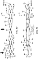
- the claimed device has two basket connector tether memory metal strips.
- the basket connector tether memory metal strips each rotate at least about fifteen degrees in the same direction relative to the proximal basket longitudinal axis and the distal basket longitudinal axis.
- the distal end of a first basket connector tether memory metal strip is located between about 90 degrees and about 270 degrees relative to the proximal end of the first basket connector tether memory metal strip, and further wherein in the collapsed state, the distal end of a second basket connector tether memory metal strip is located between about 90 degrees and about 270 degrees relative to the proximal end of the second connector tether memory metal strip.
- the height of the proximal basket is greater than the height of the distal basket and further wherein the width of the proximal basket is greater than the width of the distal basket.
- the radial force of the distal basket is less than the radial force of the proximal basket, as measured from the proximal crowns of the cells of the proximal basket attached to the plurality of proximal memory metal strips to the distal crowns of the cells of the proximal basket attached to the plurality of basket connector tether memory metal strips.
- the radial force of the proximal basket is substantially uniform from the proximal crowns of the cells of the proximal basket attached to the plurality of proximal memory metal strips to the distal crowns of the cells of the proximal basket attached to the plurality of basket connector tether memory metal strips.
- the radial force of the distal basket is substantially uniform from the proximal crowns of the cells of the distal basket attached to the plurality of basket connector tether memory metal strips to the distal-most crown of the distal cells of the distal basket.
- the proximal basket interior and the distal basket interior are generally hollow and the proximal basket cells are spaced about the circumference of the proximal basket and further wherein the distal basket cells are spaced about the circumference of the distal basket.
- the basket connector tether memory metal strips do not traverse the system interior.
- each of the distal crowns of the proximal basket connected to the basket connector tether memory metal strips are approximately the same distance from the proximal junction and further wherein each of the proximal crowns of the distal basket connected to the basket connector tether memory metal strips are approximately same distance from the distal junction.
- each of the proximal crowns of the proximal basket and distal basket are connected to a memory metal strip extending proximally from the proximal crowns and each of the distal crowns of the proximal basket and distal basket are connected to a memory metal strip extending distally from the distal crowns.
- the basket connector tether memory metal strips and the proximal tether memory metal strips form flex points of the deployable dual basket system.
- the distal end of a first proximal tether memory metal strip is located between about 90 degrees and about 270 degrees relative to the proximal end of the first proximal tether memory metal strip
- the distal end of a second proximal tether memory metal strip is located between about 90 degrees and about 270 degrees relative to the proximal end of the second proximal tether memory metal strip.
- the first and second proximal memory metal strips intersect adjacent and distal to the proximal junction.
- the basket connector tether memory metal strips form the sole attachment of the proximal basket to the distal basket.
- the present disclosure also provides a method not according to the invention of treating vasospasm using the catheter-delivered endovascular device to open a blood vessel.
- the method may involve treating a human having a subarrachnoid hemorrhage induced vasospasm in a constricted blood vessel having a proximal region having a constricted height and a constricted width and a distal region having a constricted height and a constricted width, the method comprising the steps of:
- the blood vessel is lined with endothelium and the method comprises performing steps a) - f) without damaging the endothelium.
- the present disclosure provides a catheter-delivered endovascular device comprising:
- each basket connector tether memory metal strip rotates a degree of rotation about the system circumference relative to the proximal basket longitudinal axis, the distal basket longitudinal axis and the system longitudinal axis.
- a distal crown of the proximal basket attached to the proximal end of a basket connector tether memory metal strip is offset about the system circumference relative to the proximal crown of the distal basket attached to the distal end of the same basket connector tether memory metal strip.
- the present disclosure also provide a method not according to the invention of manufacturing a medical device comprising a proximal basket and a distal basket, the method comprising:
- the present disclosure provides a deployable system, generally designated by the numeral 10, for removing an obstruction such as a blood clot 12 or other object from a blood vessel 14 or other interior lumen of an animal.
- the obstruction may be, for example, extruded coils during aneurysm treatment, intravascular embolic material such as onyx or other obstructions requiring mechanical intravascular removal from small distal vessels.
- the drawings not all reference numbers are included in each drawing for the sake of clarity.
- the deployable system 10 includes a pull wire 16 that has a proximal end (not shown) and a distal end 20.
- the diameter of the pull wire is between about 0.20 mm to about 1.29 mm (0.008 inches to about 0.051 inches).
- the pull wire 16 is comprised of a biocompatible metallic material.
- the system 10 further includes a distal body 22, which is attached to the pull wire 16.
- the distal body 22 has a proximal end 24, a distal end 26, an interior 28, and an exterior 30.
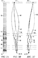
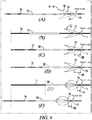
- the distal body 22 has a collapsed state, wherein the distal body 22 has a first height and width and is configured to fit into a catheter 50 (see FIG. 10A ), and a relaxed state wherein the distal body 22 has a different height 32 and width and is configured to expand to about the height and width of a human blood vessel 14 when the distal body 22 is deployed from the catheter 50 (see FIGS. 10B-G ).
- the distal body 22 further includes a proximal hub/junction 74 and a distal hub/junction 76 that is located distal relative to the proximal hub/junction 74.
- the distal body 22 includes a plurality of strips 40 comprised of a memory metal (e.g., a memory metal alloy such as nitinol) that form the proximal end 24 of the distal body 22.
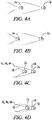
- the proximal memory metal strips 40 each have a distal end 44 and a proximal end 42 that forms an openable and closeable claw 46.
- the proximal memory metal strips 40 are attached to the proximal hub/junction 74 through connector memory metal strips 48.
- the proximal hub/junction 74 may be slideable along at least a segment of the pull wire 16, in contrast to the distal hub/junction 76, which is optionally fixed to the pull wire 16 and not slideable along the pull wire 16.
- Moving the proximal hub/junction 74 distally and closer to the distal hub/junction 76 i.e., shortening the distance 88 between the proximal hub/junction 74 and distal hub/junction 76 by moving the proximal hub/junction 74 distally while keeping the distal hub/junction 76 stationary) exerts tension on the connector memory metal strips 48 and, in turn, the proximal memory metal strips 40.
- This tension causes the proximal ends 42 of the proximal memory metal strips 40 to move radially toward each other and the pull wire 16.
- the claw 46 formed by the proximal memory metal strips 40
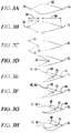
- the open position to at least a partially closed position, which in turn, separates the obstruction 12 from the wall of the human lumen 14 and captures the obstruction 12. See FIG. 3H , FIG. 8 , FIG. 9F , and FIG. 10F and 10G .
- proximal hub/junction 74 moves proximally and away from the distal hub/junction 76 (i.e., increasing the distance 88 between the hubs/junctions 74 and 76) releases the tension in the proximal memory metal strips 40, which in turn, causes the proximal ends 42 of the proximal memory metal strips 40 to move away from each other and the pull wire 16, opening the claw 46.
- the claw 46 and proximal hub/junction 74 form several functions. First, as described, closing of the claw 46 captures the obstruction 12. Second, closing the claw 46 retracts the claw 46 from the wall of the lumen 14 so that the claw 46 does not scrape against (and damage) the lumen wall while capturing the obstruction 12.
- closing the claw 46 reduces the height and width of the distal body 22, which allows the distal body 22 to be re-sheathed in the catheter 50, which may be desired, for example, if the operator seeks to re-deploy the distal body 22 in another location in the body (which may be the case if the operator originally deploys the distal body 22 in the wrong location in the lumen 14).
- "closing the claw” embraces both partially closing the claw 46 (where the proximal ends 42 of the proximal memory metal strips 40 do not contact the pull wire 16) and fully closing the claw 46 (where the proximal ends 42 contact the pull wire 16).
- the claw 46 may be comprised of any number of proximal memory metal strips 40. Preferably, however, between 2 and 4 proximal memory metal strips 40 comprise the claw 46 (it being understood that the connector strips 48, if present, merely serve to tether the claw 46 to the proximal hub/junction 74). Preferably, the proximal memory metal strips 40 have a length of between about 10 and about 60 millimeters. The proximal memory metal strips 40 can be thought of as arms of the claw 46.
- the connector strips 48 are integral with the proximal hub/junction 74 (i.e., formed from the same piece of memory metal). In other embodiments, the proximal hub/junction 74 may be welded or soldered to the connector strips 48.
- the proximal memory metal strips 42 are distributed substantially evenly about a perimeter of the distal body 22.
- the distal body 22 includes a lead wire 52 extending distally from the distal body 22.
- the lead wire 52 extends distally from the distal hub/junction 76. If present, the lead wire 52 may be used to facilitate movement of the system 10 in the lumen 14.
- the distal body 22 includes a basket 54 distal to the proximal memory metal strips 40, the basket 54 comprised of a plurality of memory metal strips 56 distal relative to the proximal memory metal strips 40.
- the distal memory metal strips 56 may, for example, form a basket 54 with a plurality of mesh openings 58.
- the size of the mesh openings 58 in the basket 54 when the distal body 22 is in its relaxed state is less (preferably significantly less) than the diameter of an average-sized ischemic blood clot 12 so that the blood clot 12 does not escape from the distal basket 54 after being captured by the distal body 22.
- the basket 54 has an open proximal end 60 and a substantially closed distal end 62, which is formed by distal tube 76.
- the distal and proximal hubs/junctions 74 and 76 and the distal basket 54 are comprised of a nitinol having the same material composition.
- the size of the mesh openings 58 decreases from the proximal end 60 of the basket 54 to the distal end 62.
- the distal basket 54 is best seen in FIG. 2 and can be comprised of a different number of cell patterns.
- the distal basket 54 is not shown in FIGs. 3-10 for ease of illustrating the other components in the system 10.
- the proximal hub/junction 74 and the distal hub/junction 76 are cylindrical tubes comprising substantially circular apertures that span the length of the hubs/junctions 74 and 76 and the hubs/junctions 74 and 76 have approximately the same inner diameter 72 and the same outer diameter 70.
- the inner diameter 72 is at least slightly larger than the diameter of the pull wire 16 so that the pull wire 16 can slide through the proximal hub/junction 74.
- the outer diameters 70 of the proximal and distal hubs/junctions 74 and 76 may be from about 0.279 mm to about 1.372 mm (0.011 inches to about 0.054 inches) and the inner diameters 72 of the proximal and distal hubs/junctions 74 and 76 may be from about 0.20 mm to about 1.29 mm (0.008 inches to about 0.051 inches).
- the distal body 22 further comprises an x-ray marker 64 that is more visible under x-ray as compared to the proximal memory metal strips 40 when the distal body 22 is located in a cranial blood vessel inside the body of a human and the x-ray is taken from outside the human's body.
- the x-ray markers 64 may be, for example, located at the welding or soldering site. In some cases, the increased thickness at the welding or soldering site may in of itself comprise the x-ray marker 64.
- the x-ray marker 64 is comprised of a radiopaque material.
- radiopaque materials can include, but are not limited to, gold, platinum, palladium, tantalum, tungsten alloy, polymer material loaded with radiopaque filler, and the like.
- the proximal memory metal strips 40 are comprised of nitinol and the x-ray marker 64 is comprised of a material having a density greater than the nitinol.
- the term "catheter” generally refers to any suitable tube through which the system 10 can be deployed.
- the catheter 50 is sterile and comprised of a biocompatible material (i.e., a material that does not irritate the human body during the course of a 45 minute operation that involves using the system 10 to remove a clot 12 from an intracranial blood vessel 14).
- the catheter 50 can be any suitable shape, including but not limited to generally cylindrical.
- the catheter 50 is a microcatheter.
- the catheter 50 envelopes the system 10
- the catheter 50 envelopes at least one component of the system 10 (preferably, the distal body 22, the lead wire 52, and the pull wire 16).
- the catheter 50 is about 2.5 French in diameter.
- the catheter 50 is delivered to the region of the lumen 14 that has the obstruction 12 as follows: a guide wire is delivered to the obstruction region past the obstruction 12; the catheter 50 is delivered over the guide wire; the guide wire is removed; and the system 10 is delivered with its pull wire 16 and lead wire 52 through the catheter 50.
- the pull wire 16 is used to push the system 10 through the catheter 50 as well as to retrieve the distal body 22 after capturing the obstruction 14 as described below.
- the system 10 may utilize a plurality of catheters 50, such as, for example, a wider catheter that travels to the brain and a very flexible, smaller diameter microcatheter that is delivered from the first catheter and travels through the small arteries of the brain.
- the catheter 50 is comprised of a biocompatible, polymeric material (i.e., one or more polymeric materials such as silicone, PVC, latex rubber or braided nylon).
- the distal body 22 or optionally just the distal basket 54 has a tapered shape (e.g., substantially conical or bullet in shape) so that the distal body 22 or just the distal basket 54 tapers from the distal body 22 or the distal basket's 54 proximal end to the distal end.
- a tapered shape e.g., substantially conical or bullet in shape
- the proximal end of the system 10 is shown at the left end of FIGs. 1 and 3-10 and the distal end of the system 10 is shown at the right end of FIGs. 1 and 3-10 because a principal use of the system 10 is to remove a blood clot 12 from a human intracranial artery 14, in which case the system 10 generally will enter the artery 14 at its proximal end by the surgeon entering the patient's body near the groin and pushing the catheter 50 towards the brain.
- the diameter of human arteries 14 generally decrease from their proximal end to their distal end.
- the distal body 22 may be located proximally relative to the catheter 50 as the term proximally and distally are used in that lumen.
- the surgeon may deploy the distal body 22 by, for example, moving the catheter 50 proximally so as to unsheathe the distal body 22 or by pushing the distal body 22 out of the catheter 50.
- a catheter 50 which contains the collapsed distal body 22 is positioned in the lumen 14 distal to the clot 12. See FIG. 10A .
- the distal body 22 is deployed from the catheter 50 and the height and width of the distal body 22 expand to about the height and width of the blood vessel 14. See FIG. 10B .
- the catheter 50 is pulled proximally and a claw-actuator tube 90 is deployed into the blood vessel 14. See FIG. 10C .
- the distal body 22 is moved proximally so that the clot 12 is located in the interior 28 of the distal body 22. See FIGs. 10D and 10E .
- the claw-actuator tube 90 is moved distally, which pushes the proximal hub/junction 74 distally so that the distance 88 between the proximal hub/junction 74 and the distal hub/junction 76 (which is fixed to the pull wire 16 and kept stationary) decreases. Distal movement of the proximal hub/junction 74 exerts tension on the connector and proximal memory metal strips 40 and 48, which in turn, closes the claw 46. See FIG. 10F .
- the claw actuator tube 90 should float on the pull wire 16 - i.e., have an aperture extending the tube's length that has a diameter larger than the diameter of the pull wire 16 - and the aperture of the claw actuator tube 90 should be smaller than the diameter of the proximal hub/junction 74 so that the claw actuator tube 90 pushes the proximal hub/junction 74).
- the system 10 is withdrawn proximally and removed from the body. See FIG. 10G .
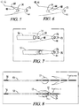
- a distal body 22 with a distal basket 54, proximal and distal hubs/junctions 74 and 76, and a claw 46 comprised of three proximal memory metal strips 42 was tested in a flow model that included a tube and a moist cotton ball located in the tube.
- the cotton ball was used to simulate a blood clot.
- the system 10 was deployed distal to the cotton ball.
- the claw 46 was closed by moving the proximal hub/junction 74 distally to capture the cotton ball.
- the system 10 and cotton ball were withdrawn proximally in the tube.
- a distal body 22 is prepared by a process that includes one or more of the following steps, as illustrated in FIGs. 1-4
- the method further includes placing the pull wire 16 through the proximal tube 74 so that the proximal tube 74 is slideable along at least a segment of the pull wire 16.
- the method further includes attaching the pull wire 16 to the distal tube 76 so that the distal tube 76 is not slideable along the pull wire 16 but instead the distal tube 76 moves with the pull wire 16.
- the proximal end 24 of the distal body 22 forms a claw 46 comprised of between 2 to 4 proximal memory metal strips 40, the claw proximal memory metal strips 40 configured to move towards each other and the pull wire 16 by moving the proximal tube 74 distally and toward the distal tube 76 (i.e., decreasing the distance 88 between the tubes 74 and 76) and the claw memory metal strips 40 configured to move away from each other and away from the pull wire (i.e., increasing the distance 88 between the tubes 74 and 76) by moving the proximal tube 76 proximally and away from the distal tube 76 (as described previously).
- the middle portion 78 is expanded by heating the mandrel and the middle portion 78 by, for example, placing the mandrel and the middle portion 78 in a fluidized sand bath at about 500°C for about 3 to about 7 minutes. As the middle portion 78 is heated, the heating causes the crystalline structure of the memory metal tube 68 to realign.
- the mandrel is tapered (e.g., substantially conical or bullet in shape) so that the distal basket 54 formed from the middle portion 78 tapers from the proximal end 60 to the distal end 62.
- the proximal and distal ends of the tube 74 and 76 are not shape set by the mandrel and are not cut by the laser 80 so that the proximal and distal ends 74 and 76 do not change in shape and only slightly expand in size under heating and return to the size of the native tube 68 after the heat is removed.
- the laser cuts are programmed via a computer.
- the laser 80 is preferably focused between the inner and outer diameter of the desired cutting surface and a coolant is passed through the memory metal tube 68 so that the laser 80 cools before reaching the surface directly opposite the desired cutting surface.
- the portions of the wall not cut by the laser 80 create the distal basket 53, proximal and distal tubes 74 and 76, and memory metal strips 40, 48 and 56, as described.
- the memory metal selected for the native tube 68 has a heat of transformation below average human body temperature (37°C) so that the distal body 22 has sufficient spring and flexibility after deployment from the catheter 50 in the human blood vessel 14.
- the native tube 68 (and hence the distal and proximal tubes 74 and 76) have an outer diameter of less than about 4 French, e.g., a diameter of about 1 to about 4 French.
- the diameter of the pull wire 16 is between about 0.20 mm to about 1.29 mm (0.008 inches to about 0.051 inches), as noted above, and in such embodiments, the diameter of the pull wire 16 may be approximately equal to the inner diameter 72 of the native nitinol tube 68.
- manufacturing the distal body 22 from a single memory metal tube 68 provides ease of manufacturing and safety from mechanical failure and provides tensile strength necessary for the system 10 to remove hard thrombus 12 and other obstructions.
- Figures 11-29 illustrate an alternate embodiment 200 that includes one or more of the following additional features, as described below: twisting proximal strips/tethers 252, unattached/free distal-pointing crowns 258 that optionally curve inward and have x-ray markers 244, and enlarged openings/drop zones 262 in the basket 246 immediately distal to the unattached, distal-pointing crowns 258 that allow the obstruction or other object 270 to enter the distal basket interior 222.
- the system 200 may include a pull wire 202 having a proximal end 204 and a distal end 206, as described above, a distal body 216 attached to the pull wire 202, the distal body 216 comprising an interior 222, a proximal end 218, a distal end 220, a distal body length 226 extending from the proximal end 218 to the distal end 220, a distal body height 224, a proximal hub/junction 228 (preferably in the form of a tube and which has a proximal end 230 and a distal end 232) forming the proximal end 218 of the distal body 216, a basket 246 comprised of a plurality of cells/openings 248 formed by a plurality of basket strips 291 that preferably are comprised of a memory metal, optionally a distal hub/junction 236 that forms the distal end 220 of the basket
- the basket interior 292 is substantially hollow - i.e., unlike U.S. Patent Publication No. 2013/0345739 , the basket interior 292 does not contain an inner elongate body.
- the basket 246 instead of a distal hub/junction 236, the basket 246 includes an open distal end.
- at least two cells 250 of the basket 246 comprise a proximal crown 260 pointing generally in the proximal direction and a distal crown 258 pointing generally in the distal direction, and the distal crowns 258 of the at least two cells 250 are not attached to another cell 248 of the basket 246.
- distal crowns 258 of at least two cells 250 are free floating and are not attached to any strip except for the strips forming part of the at least two cells 250; such distal crowns 258 are referred to below as unattached, distal-pointing crowns 258.
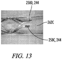
- the distal tips of the unattached, distal-pointing crowns 258 terminate at an x-ray marker 244.
- Cells labeled with the numerals 250, 250A, 250B, 250C, and 250D refer to the at least two cells that include a proximal crown 260 pointing generally in the proximal direction and an unattached, distal-pointing crown 258, cells labeled with the numerals 262, 262A, 262B, 262C, and 262D refer to the enlarged cells/drop zones adjacent to (preferably immediately distal to) an unattached, distal-pointing crown 258, and cells designated with numeral 248 refer to generally the cells of the basket 246).
- the enlarged cells/drop zones 262 are preferably immediately distal to an unattached, distal-pointing crown 258, it will be understood that at least a portion of an enlarged cell/drop zone 262 is immediately distal to an unattached, distal-pointing crown 258, and that a portion of the enlarged cell/drop zone 262 may be proximal to an unattached, distal-pointing crown 258, as shown in FIGs. 11-12 due to the shape of the enlarged cells/drop zones 262).
- part number 250 refers generally to one or more of the at least two cells
- part numbers 250A, 250B, 250C, and 250D refer to a specific one of the at least two cells.
- part number 262 refers generally to one or more of the enlarged cells/drop zones
- part numbers 262A, 262B, 262C, and 262D refer to a specific one of the enlarged cells/drop zones
- part number 258 refers generally to one or more of the unattached, distal-pointing crowns
- part numbers 258A, 258B, 258C, and 258D refer to a specific one of the unattached, distal-pointing crowns.
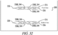
- At least two of the unattached, distal-pointing crowns 258 are located approximately 180 degrees (e.g., about 150 to about 180 degrees) relative to each other and approximately the same distance from the proximal hub/junction/tube 228, as best seen in FIG. 12A .
- the basket 246 comprises a first pair of unattached, distal-pointing crowns 258A and 258B, each of the first pair of unattached, distal-pointing crowns 258A and 258B is located approximately the same distance from the proximal hub/junction/tube 228 and approximately 180 degrees relative to each other, and the basket 246 further comprises a second pair of unattached, distal-pointing crowns 258C and 258D located distally relative to, and approximately 90 degrees (e.g., between about 60 and about 90 degrees) relative to, the first pair of unattached, distal-pointing crowns 258A and 258B.
- the second pair of unattached, distal-pointing crowns 258C and 258D form cells 250C and 250D that are adjacent to, but offset from, the cells 250A and 250B formed by the first pair of unattached, distal-pointing crowns 258A and 258B.
- the center of cell 250A is about 90 degrees relative to the centers of cells 250C and 250D and optionally the center of cell 250B is also about 90 degrees relative to the centers of cells 250C and 250D).
- At least one of (and preferably all) the unattached, distal-pointing crowns 258A, 258B, 258C or 258D comprise an x-ray marker 244 that is more visible under x-ray as compared to the basket strips 291 when the distal body 216 is located in a cranial blood vessel 266 inside the body of a human and the x-ray is taken from outside the human's body.
- the x-ray marker 244 is a radiopaque material.
- radiopaque materials can include, but are not limited to, gold, platinum, palladium, tantalum, tungsten alloy, polymer material loaded with radiopaque filler, and the like.
- the basket strips 291 are comprised of nitinol and the x-ray marker 244 is comprised of a material having a density greater than the nitinol.
- the x-ray markers 244 comprise a heavy metal welded or soldered to the unattached, distal-pointing crowns 258.
- the unattached, distal-pointing crowns 258 curve subtly towards the interior 222 of the distal basket 246, which decreases the likelihood that the unattached, distal-pointing crowns 258 will rub against and damage the vessel wall 268.
- the basket 246 comprises at least two cells proximal to the at least two cells 250 that include the unattached, distal-pointing crowns 258.
- the unattached, distal-pointing distal crowns 258 are located about at least 5 mm (e.g., about 5 to about 30 mm) from the proximal hub/junction/tube 228.
- the unattached, distal-pointing crowns 258 are located at least about 5 mm from the distal hub/junction/tube 236.
- the unattached, distal-pointing crowns 258 of the at least two cells 250 also each form part (namely a portion of the proximal boundary) of an enlarged cell 262 (which is the entry point of hard thrombus 270B into the basket interior 222) and further wherein the surface area of the enlarged cells 262 in the relaxed state is greater than the surface area of the other cells of the basket 246 in the relaxed state.
- the unattached, distal-pointing crowns 258 serve several functions: 1) they form flex points of the basket 246, which makes it easier for the system 200 to navigate the curves of the blood vessels 266 of the brains; 2) through the use of x-ray markers 244 on the unattached, distal-pointing crowns 258, they allow the operator to locate the enlarged cells 262 of the basket 246 that form the point at which hard thrombuses 270B enter the basket 246; and 3) they allow the operator to ratchet or force the object 270 into the basket 246 by moving the unattached, distal-pointing crowns 258 proximally and distally relative to the object 270.
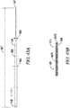
- proximal end 254 of a proximal strip 252 is located about 65-180 degrees (preferably approximately 180 degrees) relative to the distal end 256 of the same proximal strip 252, as best seen in FIG. 12B .
- proximal end 254 of a first proximal strip 252 is attached to the 12 o'clock position on the proximal tube 228 and the distal end 256 of the first proximal strip 252 (which terminates at a proximal cell 248 of the basket 246) is located at the 6 o'clock position (i.e., 180 degrees from the start position), and the proximal end 254 of a second proximal strip 252 is attached to the 6 o'clock position on the proximal tube 228 and the distal end 254 (which terminates at a cell 248 of the basket 246) of the second proximal strip 252 is located at the 12 o'clock position (i.e., 180 degrees from the start position).
- This twisting feature serves two functions: 1) it allows the proximal strips 252 to surround the object 270; and 2) it allows the manufacturer to insert a mandrel into the basket 246 during the shape-setting procedure.
- the pull wire 202 is attached to the proximal tube 228 (e.g., by gluing, welding, soldering or the like).
- the pull wire 202 does not extend through the distal basket interior 222.
- the proximal strips 252 are integral with the distal end 232 of the proximal tube 228 and the entire distal body 216 is created from a single tube 264 of a memory metal.
- the proximal crowns 260 of the at least two cells 250 that include the unattached, distal pointing-crowns 258 are each attached to another cell 248 of the basket 246.
- the basket 246 does not have any free-floating proximal-pointing crowns, as free-floating proximal-pointing crowns could damage the vessel 266 when the distal body 216 is pulled proximally.
- the system 200 further comprises a lead wire 286 extending distally from the distal tube 236, the lead wire 286 having a length of from about 3 mm to about 10 mm
- the distal hub/junction/tube 236, the proximal hub/junction/tube 228, and the basket 246 are comprised of a nitinol having the same material composition.
- the entire distal body 216 is manufactured from a single tube of nitinol 264.
- the proximal and distal hubs/junctions/tubes 228 and 236 comprise an x-ray marker 244 that is more visible under x-ray as compared to the basket strips 291 when the distal body 216 is located in a cranial blood vessel 266 inside the body of a human and the x-ray is taken from outside the human's body.
- the x-ray marker 244 is a radiopaque material.
- radiopaque materials can include, but are not limited to, gold, platinum, palladium, tantalum, tungsten alloy, polymer material loaded with radiopaque filler, and the like.
- the basket strips 291 are comprised of nitinol and the x-ray marker 244 is comprised of a material having a density greater than the nitinol.
- the proximal and distal hubs/junctions/tube interiors 234 and 242 may comprise tantalum welded or otherwise attached to the interior 234 and 242 of the proximal and distal hubs/junctions/tubes 228 and 236.
- the proximal and the distal tubes 228 and 236 are generally cylindrical in shape and each has an outer diameter and an inner diameter, the inner diameter forming apertures of the proximal and distal tubes 228 and 236 and further wherein the outer diameters of the proximal and distal tubes 228 and 236 are substantially the same size and further wherein the inner diameters of the proximal and distal tubes 228 and 236 are substantially the same size.
- the outer diameters of the proximal and distal tubes 228 and 236 are from about 0.279 mm to about 1.372 mm (0.011 inches to about 0.054 inches), and further wherein the inner diameters of the proximal and distal tubes 228 and 236 are from about 0.20 mm to about 1.29 mm (0.008 inches to about 0.051 inches).
- the pull wire 202 is generally cylindrical and further wherein the diameter of the pull wire 202 is between about 0.20 mm to about 1.29 mm (0.008 inches to about 0.051 inches).
- the distal body 216 has a length of between about 10 and about 60 millimeters.
- the first height 224 and first width 226 of the distal body 216 are between about 2 millimeters and about 6 millimeters.
- the present disclosure also provides a method, not according to the invention, of removing a clot or other object 270 from an interior lumen 266 of an animal, the method comprising the steps of:
- the object 270 enters the distal basket interior 222 adjacent to (preferably adjacent and immediately distal to) at least one of the unattached, distal-pointing crowns 258 - i.e., in the enlarged cells/drop zones 262.
- the distal body 216 is deployed so that at least one (e.g., preferably the two proximal 258A and 258B) of the unattached, distal-pointing crowns 258 is distal to the object 270.
- the x-ray markers 244 of the unattached, distal-pointing crowns 258 are used to locate the distal body 216 relative to the clot or other object 270.
- clots 270 can generally be located in blood vessels 266 by injecting a contrast dye, for example, into the blood vessel 266 proximal and distal to the believed area of obstruction and viewing on an x-ray where the fluid stops moving in the blood vessel 266. It will also appreciated that if the object 270 is not a blood clot but is a radio-opaque object, the object 270 may be viewed on an x-ray.
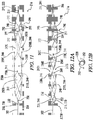
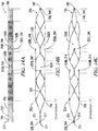
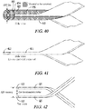
- FIGs. 11 and 14B illustrate a first, perspective view of one embodiment of a distal body 216 with twisting proximal strips 252, unattached distal-pointing crowns 258 that subtly curve inward and have x-ray markers 244, and enlarged openings/drop zones 262 in the basket 246 that allow the obstruction or other object 270 to enter.
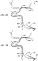
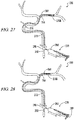
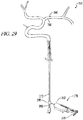
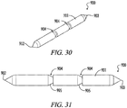
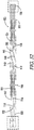
- the distal body 216 is in Orientation 1. (To prepare a basket 246 with unattached distal-pointing crowns 258 that curve inward toward the basket interior 292, a mandrel 900 such as that illustrated in FIGs. 30 and 31 may be used.
- the mandrel 900 includes a generally cylindrical body 901 with tapered proximal and distal ends 902 and 903 that slope like the ends of a pencil.
- the cylindrical body 901 includes two grooves 904 that extend around the circumference of the cylindrical body 901.
- the grooves 904 include tapered portions 905 that slope towards the distal end 903, which are designed to shape the unattached distal-pointing crowns 258.
- the grooves 904 are generally in the shape of a truncated cone, as shown in FIGs. 30-31 ).
- the two proximal, unattached distal-pointing crowns 258A and 258B are located approximately the same distance from the proximal hub/junction/tube 228 and are oriented approximately 180 degrees relative to each other.
- the two distal, unattached distal-pointing crowns 258C and 258D are located approximately the same distance from the proximal hub/junction/tube 228 as each other (and distal to the two proximal, unattached distal-pointing crowns 258A and 258B) and are oriented approximately 180 degrees relative to each other and approximately 90 degrees to the proximal, unattached distal-pointing crowns 258A and 258B.
- the two proximal enlarged openings/drop zones 262A and 262B distal to the proximal, unattached distal pointing crowns 258A and 258B are located approximately the same distance from the proximal hub/junction/tube 228 and the centers of the two proximal enlarged openings/drop zones 262A and 262B are oriented approximately 180 degrees relative to each other.
- the proximal, unattached distal-pointing crowns 258A and 258B form part of the proximal boundary of the proximal, enlarged cells/drop zones 262A and 262B
- the distal, unattached distal-pointing crowns 258C and 258C form part of the proximal boundary of the distal, enlarged cells/drop zones 262C and 262D).
- FIGs. 12A and 14C illustrate a second view of the distal body 216 of FIG. 11 (Orientation 2).
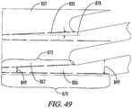
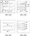
- FIG. 13 is a close-up view of two unattached, distal-pointing crowns 262. The lines in FIG.
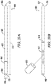
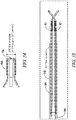
- FIG. 14 show how a nitinol tube 264 is cut with a laser to create the distal body 216 shown in FIG. 14B and FIG. 14C . It will be appreciated that FIG. 14B is a simplified view of the distal body 216 and orientation shown in FIG. 11 and FIG. 14C is a simplified view of the distal body 216 and orientation shown in FIG. 12A .
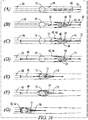
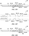
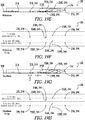
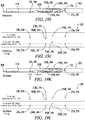
- FIGs. 15-19 describe how the distal body 216 is used to retrieve, soft clots 270A, hard clots 270B, and deformable, cohesive adhesive clots 270C in a human intracranial artery 266.
- the center of the artery 266 is denominated by the dashed line).
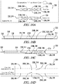
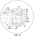
- the distal body 216 has four rows of x-ray markers namely, 1) a first row of one x-ray marker, which is located inside the proximal tube denominated by the numeral 228, 244; 2) a second row of two x-ray markers, which are located at the two proximal, unattached distal-pointing crowns (the two markers are oriented 180 degrees relative to each other) denominated by the numerals 258A, 244 and 258B, 244; 3) a third row of two x-ray markers, which are located at the two distal, unattached distal-pointing crowns (these two markers are oriented 180 degrees relative to each other and 90 degrees relative to the two proximal, unattached distal-pointing crowns) denominated by the numerals 258C, 244 and 258D, 244; and 4) a fourth row of one x-ray marker, which is located inside the distal tube denominated by the numeral 236, 24
- the first number in the sequence describes the position of the x-ray marker and the second number, 244, represents the fact that the item is an x-ray marker).
- the surgeon interventionalist i.e., operator of the distal body 216 detects the four rows of x-ray markers using x-ray radiation from a first vantage point and from a second vantage point that is offset from the first vantage point (e.g. 90 degrees).
- the surgeon moves the distal body 216 proximally relative to the clot 270 and takes additional x-rays from the first and second vantage points.
- the surgeon uses the x-ray markers of the proximal and distal, unattached distal-pointing crowns, namely 258A, 244; 258B, 244; 258C, 244; and 258D, 244 (more specifically, the convergence or lack thereof of the proximal and distal, unattached distal-pointing crowns 258A, 244; 258B, 244; 258C, 244; and 258D, 244 as shown on the x-ray) to determine whether the clot 270 is located inside the distal body interior 222 or whether the clot 270 is collapsing the distal body 216.
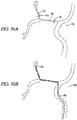
- FIGs. 15A-G illustrate stepwise use of the distal body 216 in retrieving a soft clot 270A in a human intracranial artery 266.
- the distal body 216 in FIGS. 15A-15G is in Orientation 1).
- the surgeon determines the location of the clot 270A in the vessel 266 using, for example, a contrast dye injected proximal and distal to the clot 270A.
- the delivery catheter 208 which is enveloping the distal body 216, is positioned in the blood vessel 266 so that the two proximal, unattached distal-pointing crowns 258A and 258B are immediately distal to the clot 270A. See FIG.
- the distal body 216 is then deployed from the delivery catheter 208 by moving the catheter 208 proximally.
- the soft clot 270A which is unable to collapse the distal body 216, then enters the distal body interior 222. See FIG. 15C .
- the surgeon is unaware that the clot 270A has entered into the distal body interior 222.
- the surgeon irradiates the four rows of x-ray markers at a first vantage point (i.e., from the front of the distal body 216 in the orientation shown in FIGs. 15A-G ; i.e., into the page). As shown in FIG.
- the first vantage point shows four rows of x-ray markers.
- the first row is a single point, which represents the x-ray marker located in the proximal tube 228, 244; the proximal tube x-ray marker 228, 244 always appears as a single point.
- the second row is a single point, which represents the x-ray marker located at the front, proximal, unattached distal-pointing crown 258B, 244; the reason that this second row of markers is a single point is that the rear x-ray marker of the second row 258A, 244 is hidden from view because it is directly behind the front x-ray marker of the second row 258B, 244.
- the third row has two points, which represents the two x-ray markers located at the distal, unattached distal-pointing crowns 258C, 244 and 258D, 244; the reason that this third row of markers has two points is that neither marker in the third row 258C, 244 and 258D, 244 is hidden from view on the x-ray at this angle - rather, one marker 258C, 244 is located above the other marker 258D, 244 - and as shown in FIG. 15C , the distal body 216 is not collapsed at the distal, unattached distal-pointing crowns 258C, 244 and 258D, 244.
- the fourth row is a single point, which represents the x-ray marker located in the distal tube 236, 244; the distal tube x-ray marker 236, 244 always appears as a single point. Without moving the distal body 216, the surgeon then irradiates the four rows of x-ray markers from a second vantage point 90 degrees offset from the first vantage point (i.e., from the bottom of the distal body 216 in the orientation shown in FIG. 15A ). As shown, the first row is, as always, a single point, which represents the x-ray marker located in the proximal tube 228, 244.
- the second row has two points, which represents the two x-ray markers located at the proximal, unattached distal-pointing crown 258A, 244 and 258B, 244; the reason that this second row of markers shows up as two points is that neither marker 258A, 244 and 258B, 244 in the second row is hidden from view on the x-ray at this offset angle - rather, one marker 258B, 244 is located above the other marker 258A, 244 - and the distal body 216 is not collapsed at the proximal, unattached distal-pointing crowns 258A, 244 and 258B, 244.
- the third row is a single point, which represents the x-ray marker located at the bottom, distal, unattached distal-pointing crown 258D, 244; the reason that this third row of markers is a single point is that the top x-ray marker of the third row 258C, 244 is directly behind the bottom x-ray marker of the third row 258D, 244, and thus, hidden from view.
- the fourth row is, as always, a single point, which represents the x-ray marker located in the distal tube 236, 244.
- the surgeon concludes that the clot is a soft clot 270A that has entered into the distal body interior 222 and the surgeon removes the distal body 216 and the soft clot 270A, captured by the distal body 216, by moving the distal body 216 proximally out of the vessel 266, as shown in FIG. 15G .
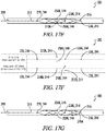
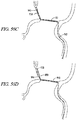
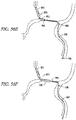
- FIGs. 16A-H illustrate stepwise use of the distal body 216 in retrieving a hard clot 270B in a human intracranial artery 266.
- the distal body 216 is in Orientation 1).
- the surgeon determines the location of the clot 270B in the vessel 266 using, for example, a contrast dye injected proximal and distal to the clot 270B.
- the delivery catheter 208 which is enveloping the distal body 216, is positioned in the blood vessel 266 so that the two proximal, unattached distal-pointing crowns 258A and 258B are immediately distal to the clot 270B. See FIG.
- the distal body 216 is then deployed from the delivery catheter 208 by moving the catheter 208 proximally.
- the hard clot 270B which is located above the distal body 216, collapses the distal body 216, as shown in FIG. 16C .
- the surgeon is unaware that the clot 270B has collapsed the distal body 216.
- the surgeon irradiates the x-ray markers at a first vantage point (i.e., from the front of the distal body 216; i.e., into the page).
- the first vantage point shows four rows of x-ray markers.
- the first row is, as always, a single point, representing the x-ray marker located in the proximal tube - i.e., 228, 244.
- the second row is a single point, which represents the x-ray marker located at the front, proximal, unattached distal-pointing crown 258B, 244; the reason that this second row of markers is a single point is that the rear x-ray marker of the second row 258A, 244 is hidden from view because it is directly behind the front x-ray marker of the second row 258B, 244.
- the third row has two points, which represents the two x-ray markers located at the distal, unattached distal-pointing crowns 258C, 244 and 258D, 244; the reason that this third row of markers has two points is that neither marker in the third row is hidden from view on the x-ray at this angle - rather, one marker 258C, 244 is located above the other marker 258D, 244 - and as shown in FIG. 16C , the distal body 216 is not collapsed at the distal, unattached distal-pointing crowns 258C, 244 and 258D, 244.
- the fourth row is, as always, a single point, representing the x-ray marker located in the distal tube 236, 244.
- the surgeon then irradiates the markers from a second vantage point 90 degrees offset from the first vantage point (i.e., from the bottom of the distal body 216).
- the first row is, as always, a single point, which represents the x-ray marker located in the proximal tube 228, 244.
- the second row has two points, which represents the two x-ray markers located at the proximal, unattached distal-pointing crowns 258A, 244 and 258B, 244; the reason that this second row of markers shows up as two points is that neither marker in the second row is hidden from view on the x-ray at this offset angle - rather, one marker 258B, 244 is located above the other marker 258A, 244 - and although the distal body 216 is collapsed at the proximal, unattached distal-pointing crowns as shown in FIG. 16C , the second row of x-ray markers have not converged because the clot 270B is on top of the second row of x-ray markers.
- the third row is a single point, which represents the x-ray marker located at the bottom, distal, unattached distal-pointing crown 258D, 244; the reason that this third row of markers is a single point is that the top x-ray marker of the third row 258C, 244 is directly behind the bottom x-ray marker of the third row 258D, 244, and thus, hidden from view.
- the fourth row is, as always, a single point, which represents the x-ray marker located in the distal tube 236, 244.
- the surgeon concludes that neither the second row 258A, 244 and 258B, 244 nor the third row 258C, 244 and 258D, 244 of x-ray markers (i.e., the x-ray markers at both the proximal and distal unattached distal pointing-crowns) has converged.
- the surgeon then moves the distal body 216 proximally so that the distal, unattached distal-pointing crowns 258C, 244 and 258D, 244 are immediately distal to the clot 270B and the surgeon then irradiates the x-markers again from the first vantage point.
- FIG. 16E the surgeon then moves the distal body 216 proximally so that the distal, unattached distal-pointing crowns 258C, 244 and 258D, 244 are immediately distal to the clot 270B and the surgeon then irradiates the x-markers again from the first vantage point.
- the first row is, as always, a single point, representing the x-ray marker located in the proximal tube 228, 244.
- the second row is a single point, which represents the x-ray marker located at the front, proximal, unattached distal-pointing crown 258B, 244; the reason that this second row of markers is a single point is that the rear x-ray marker of the second row 258A, 244 is hidden from view because it is directly behind the front x-ray marker of the second row 258B, 244.
- the third row has only one point because the clot 270B, which is on top of the third row of x-ray markers 258C, 244 and 258D, 244 (i.e., the markers at the distal, unattached distal-pointing crowns), has pushed the third row of x-ray markers 258C, 244 and 258D, 244 together.
- the fourth row is, as always, a single point, representing the x-ray marker located in the distal tube 236, 244. Without moving the distal body 216, the surgeon then irradiates the markers from a second vantage point 90 degrees offset from the first vantage point (i.e., from the bottom of the distal body).
- the first row is, as always, a single point, which represents the x-ray marker located in the proximal tube 228, 244.
- the second row has two points, which represents the two x-ray markers located at the proximal, unattached distal-pointing crown 258A, 244 and 258B, 244; the reason that this second row of markers shows up as two points is that neither marker in the second row is hidden from view on the x-ray at this offset angle and the distal body 216 is not collapsed at the proximal, unattached distal-pointing crowns 258A, 244 and 258B, 244.
- the third row is a single point, which represents the x-ray marker located at the bottom, distal, unattached distal-pointing crown 258D, 244; the reason that this third row of markers is a single point is that the bottom x-ray marker of the third row 258D, 244 is directly in front of the top x-ray marker of the third row 258C, 244, and thus, the top x-ray marker of the third row 258C, 244 is hidden from view.
- the fourth row is, as always, a single point, which represents the x-ray marker located in the distal tube 236, 244. Knowing that the distal, unattached distal-pointing crowns 258C, 244 and 258D, 244 have converged as shown in FIG.
- 16H shows that the distal, unattached distal-pointing crowns 258C, 244 and 258D, 244 are not converged, and, thus, the surgeon concludes that the hard clot 270B has entered the distal body interior 222. The surgeon then removes the distal body 216 and the hard clot 270B, captured by the distal body 216, by moving the distal body 216 proximally out of the vessel 266.
- FIGs. 17A-G illustrate stepwise use of the distal body 216 in retrieving a soft clot 270A in a human intracranial artery 266.
- the distal body 216 is in Orientation 2.
- the surgeon determines the location of the clot 270A in the vessel 266 using, for example, a contrast dye injected proximal and distal to the clot 270A.
- the delivery catheter 208 which is enveloping the distal body 216, is positioned in the blood vessel 266 so that the two proximal, unattached distal-pointing crowns 258A and 258B are immediately distal to the clot 270A. See FIG.
- the distal body 216 is then deployed from the catheter 208 by moving the catheter 208 proximally.
- the soft clot 270A which is unable to collapse the distal body 216, then enters the distal body interior 222. See FIG. 17C .
- the surgeon is unaware that the clot 270A has entered into the distal body interior 222.
- the surgeon irradiates the x-ray markers at a first vantage point (i.e., from the front of the distal body; into the page).
- the first vantage point shows four rows of x-ray markers.
- the first row is, as always, a single point, representing the x-ray marker located in the proximal tube 228, 244.
- the second row has two points, which represents the two x-ray markers located at the proximal, unattached distal-pointing crowns 258A, 244 and 258B, 244; the reason that this second row of markers has two points is that neither marker in the second row is hidden from view on the x-ray at this angle - rather, one marker 258A, 244 is located above the other marker 258B, 244 - and as shown in FIG. 17C , the distal body 216 is not collapsed at the proximal, unattached distal-pointing crowns 258A, 244 and 258B, 244.
- the third row has a single point, which represents the x-ray marker located at the front (in Orientation 2), distal, unattached distal-pointing crown 258C, 244; the reason that this third row of markers is a single point is that the rear (in Orientation 2) x-ray marker 258D, 244 of the third row is hidden from view because it is directly behind the front x-ray marker 258C, 244 of the third row.
- the fourth row is, as always, a single point, representing the x-ray marker located in the distal tube 236, 244.
- the surgeon then irradiates the markers from a second vantage point 90 degrees offset from the first vantage point (i.e., from the bottom of the distal body, as shown in this view).
- the first row is, as always, a single point, which represents the x-ray marker located in the proximal tube 228, 244.
- the second row is a single point, which represents the x-ray marker located at the bottom (in Orientation 2), proximal, unattached distal-pointing crown 258B, 244; the reason that this second row of markers is a single point is that the top (in Orientation 2) x-ray marker of the second row 258A, 244 is directly behind the bottom x-ray marker of the second row 258B, 244, and thus, hidden from view.
- the third row has two points, which represents the two x-ray markers located at the distal, unattached distal-pointing crowns 258C, 244 and 258D, 244; the reason that this third row of markers shows up as two points is that neither marker in the third row is hidden from view on the x-ray at this offset angle and the distal body 216 is not collapsed at the distal, unattached distal-pointing crowns 258C, 244 and 258D, 244.
- the fourth row is, as always, a single point, which represents the x-ray marker located in the distal tube 236, 244.
- the surgeon concludes that neither the second row 258A, 244 and 258B, 244 nor the third row of x-ray markers 258C, 244 and 258D, 244 (i.e., the x-ray markers at both the proximal and distal unattached distal pointing-crowns) has converged.
- the surgeon then moves the distal body 216 proximally relative to the clot 270A so that the distal, unattached distal-pointing crowns 258C, 244 and 258D, 244 are immediately distal to the clot 270A and then the surgeon irradiates the x-markers again from the first vantage point and the second vantage point.
- the results are the same as FIG. 17D .
- the surgeon concludes that neither the second row 258A, 244 and 258B, 244 nor the third row of x-ray markers 258C, 244 and 258D, 244 (i.e., the x-ray markers at both the proximal and distal unattached distal pointing-crowns) were converged at either the original position of the distal body 216 ( FIG. 17C and 17D ) or the position after moving the distal body 216 proximally ( FIG. 17E and 17F ), and, thus, the distal body 216 was expanded in the vessel 266 in both positions.
- the surgeon concludes that the clot 270A is a soft clot 270A that has entered into the distal body interior 222 and the surgeon removes the distal body 216 and the soft clot 270A, captured by the distal body 216, by moving the distal body 216 proximally out of the vessel 266, as shown in FIG. 17G .
- FIGs. 18A-G illustrate stepwise use of the distal body 216 in retrieving a hard clot 270B in a human intracranial artery 266.
- the distal body 216 is in Orientation 2.
- the primary differences between FIGs 18A-G and FIGs. 16A-G is that the clot 270B enters the distal body interior 222 in an enlarged cell/drop zone 262A immediately distal to one of the proximal, unattached distal-pointing crowns 258A in FIGs. 18A-G , as compared to FIGs.
- the clot 270B enters the distal body interior 222 in an enlarged cell/drop zone 262C immediately distal to one of the distal, unattached distal-pointing crowns 258C ).
- the surgeon determines the location of the clot 270B in the vessel 266 using, for example, a contrast dye injected proximal and distal to the clot 270B.
- the delivery catheter 208 which is enveloping the distal body 216, is positioned in the blood vessel 266 so that the two proximal, unattached distal-pointing crowns 258A and 258B are immediately distal to the clot 270B. See FIG. 18B .
- the distal body 216 is then deployed from the catheter 208 by moving the catheter 208 proximally.
- the hard clot 270B which is located above the distal body 216, collapses the distal body 216, as shown in FIG. 18C .
- the surgeon is unaware that the clot 270B has collapsed the distal body 216.
- the surgeon irradiates the x-ray markers at a first vantage point (i.e., from the front of the distal body in Orientation 2; into the page).
- the first vantage point shows four rows of x-ray markers.
- the first row is, as always, a single point, representing the x-ray marker located in the proximal tube 228, 244.
- the second row has only one point because the clot 270B, which is on top of the second row of x-ray markers 258A, 244 and 258B, 244 (i.e., the markers at the proximal, unattached distal-pointing crowns), has pushed them together.
- the third row has only one point, which represents the x-ray marker located at the front (in Orientation 2), proximal, unattached distal-pointing crown 258C, 244; the reason that this third row of markers is a single point is that the rear (in this view) x-ray marker of the third row 258D, 244 is hidden from view because it is directly behind the front x-ray marker of the third row 258C, 244.
- the fourth row is, as always, a single point, representing the x-ray marker located in the distal tube 236, 244. Without moving the distal body, the surgeon then irradiates the markers from a second vantage point 90 degrees offset from the first vantage point (i.e., from the bottom of the distal body 216 ).
- the first row is, as always, a single point, which represents the x-ray marker located in the proximal tube 228, 244.
- the second row has a single point because the top (in Orientation 2) x-ray marker of the second row 258A, 244 is located behind the bottom (in Orientation 2) x-ray marker 258B, 244 and thus, the top x-ray marker of the second row 258A, 244 is hidden from view.
- the third row has two points, which represents the x-ray markers located at the distal, unattached distal-pointing crowns 258C, 244 and 258D, 244 ; in this x-ray view neither of the x-ray markers of the third row is hidden from view.
- the fourth row is, as always, a single point, which represents the x-ray marker located in the distal tube 236, 244.
- the surgeon concludes that the second row of x-ray markers 258A, 244 and 258B, 244 (i.e., the x-ray markers at the proximal, unattached distal pointing-crowns) has converged.
- the surgeon then moves the distal body 216 proximally so that the distal, unattached distal-pointing crowns 258C, 244 and 258D, 244 are immediately distal to the clot 270B.
- the clot 270B enters the distal body interior 222 immediately distal to the top (in Orientation 2), proximal unattached distal-pointing crown 258A and the distal body 216 is no longer collapsed. The surgeon then irradiates the x-markers again from the first vantage point. As shown in FIG. 18F , the first row is, as always, a single point, representing the x-ray marker located in the proximal tube 228, 244.
- the second row has two x-ray markers because the distal body 216 is not collapsed and neither the top (in Orientation 2) 258A, 244 nor the bottom 258B, 244 (in Orientation 2) x-ray marker of the second row (i.e., the marker at the proximal, unattached distal-pointing crowns) is hidden from view.
- the third row has only one point because the rear (in Orientation 2), distal unattached distal-pointing crown 258D, 244 is hidden behind the front (in Orientation 2), distal, unattached distal pointing-crown 258C, 244.
- the fourth row is, as always, a single point, representing the x-ray marker located in the distal tube 236, 244.
- the surgeon then irradiates the markers from a second vantage point 90 degrees offset from the first vantage point (i.e., from the bottom of the distal body 216 ).
- the first row is, as always, a single point, which represents the x-ray marker located in the proximal tube 228, 244.
- the second row has a single point because the x-ray marker at the top (in Orientation 2), proximal, unattached distal-pointing crown 258A, 244 is hidden behind the bottom (in Orientation 2), proximal, unattached-distal pointing crown 258B, 244.
- the third row has two points because neither the front nor the rear x-ray markers at the distal, unattached, distal-pointing crowns 258C, 244 and 258D, 244 is hidden from view.
- the fourth row is, as always, a single point, which represents the x-ray marker located in the distal tube 236, 244. Based on the information from FIGs. 18D and 18F , the surgeon concludes that the clot 270B has entered into the distal body interior 222. The surgeon then removes the distal body 216 and the hard clot 270B, captured by the distal body 216, by moving the distal body 216 proximally out of the vessel 266, as shown in FIG. 18G . Upon comparing FIGs.
- the orientation of the enlarged cells/drop zone 262A-D relative to the orientation of a hard clot 270B determine which enlarged cell/drop zone 262A, 262B, 262C, or 262D, the hard clot 270 enters the distal body interior 222 through.
- the hard clot 270B is located above the distal body 216, and thus, the hard clot 270B must enter through the enlarged cell/drop zone located at the top of the distal body, which in the orientation of the distal body shown in FIGs.
- the hard clot 270B is again located above the distal body and, thus, the hard clot 270B must enter through the enlarged cell/drop zone located at the top of the distal body.
- the enlarged cell/drop zone located at the top of the distal body 216, in the orientation of the distal body 216 shown in FIGs. 18A-G is the enlarged cell/drop zone 262A immediately distal to the top, proximal, unattached, distal-pointing crown 258A.
- FIGs. 19A-N illustrate stepwise use of the distal body 216 in retrieving a deformable cohesive, adherent clot 270C- i.e., a clot that is difficult to break up and is tightly adhered to the vessel wall 268 - in a human intracranial artery 266.
- the distal body 216 is in Orientation 2.
- the surgeon determines the location of the clot 270C in the vessel 266 using, for example, a contrast dye injected proximal and distal to the clot 270C.
- the delivery catheter 208 which is enveloping the distal body 216, is positioned in the blood vessel 266 so that the two proximal, unattached distal-pointing crowns 258A and 258B are immediately distal to the clot 270C. See FIG. 19B .
- the distal body 216 is then deployed from the catheter 208 by moving the catheter 208 proximally.
- the deformable, cohesive adherent clot 270C which is located above the distal body 216, collapses the distal body 216, as shown in FIG. 19C . However, at this time, the surgeon is unaware that the clot 270C has collapsed the distal body 216.
- the surgeon irradiates the x-ray markers at a first vantage point (i.e., from the front of the distal body; i.e., into the page).
- a first vantage point i.e., from the front of the distal body; i.e., into the page.
- the first vantage point shows four rows of x-ray markers.
- the first row is, as always, a single point, representing the x-ray marker located in the proximal tube 228, 244.
- the second row has a single point, corresponding to the top (in Orientation 2) and bottom (in Orientation 2), proximal, unattached distal-pointing crowns 258A, 244 and 258B, 244, which have converged because the clot 270C is collapsing the distal body 216.
- the third row has a single point, which represents the x-ray marker located at the front (in Orientation 2), distal, unattached distal-pointing crown 258C, 244; the x-ray marker located at the rear, distal, unattached distal-pointing crown 258D, 244 is hidden from view.
- the fourth row is, as always, a single point, representing the x-ray marker located in the distal tube 236, 244. Without moving the distal body 216, the surgeon then irradiates the markers from a second vantage point 90 degrees offset from the first vantage point (i.e., from the bottom of the distal body). As shown, the first row is, as always, a single point, which represents the x-ray marker located in the proximal tube 228, 244.
- the second row has a single point, which corresponds to the bottom (in Orientation 2), proximal, unattached distal-pointing crown 258B, 244 ; the top (in Orientation 2), proximal, unattached distal-pointing crown 258A, 244 is located behind the bottom, proximal, unattached distal-pointing crown 258B, 244 and hidden from view.
- the third row has two points, which correspond to the front (in Orientation 2) 258C, 244 and rear 258D, 244 (in Orientation 2), distal, unattached distal-pointing crowns, neither of which is blocked in this view.
- the fourth row is, as always, a single point, which represents the x-ray marker located in the distal tube 236, 244.
- the surgeon then moves the distal body 216 proximally (i.e., slightly withdraws the distal body 216 ).
- the surgeon then irradiates the x-markers again from the first and second vantage points.
- FIG. 19F the results are exactly the same as in FIG. 19D . Based on the observation that the proximal, unattached distal-pointing crowns 258A, 244 and 258B, 244 have converged at both the original position ( FIGs.
- the surgeon concludes that the clot 270C is a deformable cohesive, adherent clot 270C.
- the surgeon then oscillates the distal body 216 proximally and distally a small distance (e.g., about 1mm to about 2 mm) in the vessel 266, and the clot 270C begins to enter the distal body 216, as shown in FIG. 19G .
- the surgeon then irradiates the x-markers again from the first and second vantage points.
- the results are exactly the same as in FIG. 19D and FIG. 19F except that the second row of markers 258A, 244 and 258B, 244 (at the proximal, unattached distal-pointing crowns) are beginning to move apart.
- the surgeon then moves the distal body 216 proximally again, as shown in FIG. 19I .
- the surgeon then irradiates the x-markers again from the first and second vantage points.
- FIG. 19J the results are exactly the same as in FIGs. 19D and 19F , as the clot 270C has caused the second row of markers 258A, 244 and 258B, 244 to re-converge.
- the surgeon then irradiates the x-markers again from the first and second vantage points.
- the results show that the second row of markers 258A, 244 and 258B, 244 (at the proximal, unattached distal-pointing crowns) have moved apart.
- the surgeon concludes that the deformable cohesive, adherent clot 270C has been sufficiently captured by the distal body 216 and the surgeon then removes the distal body 216 and the clot 270C, captured by the distal body 216, by moving the distal body 216 proximally out of the vessel 266.
- the x-ray markers at the proximal and distal, unattached distal-pointing crowns 258A-D, 244 provide the surgeon feedback concerning the interaction between the distal body 216 and the clot 270 in the blood vessel 266.
- the guiding principle of a soft clot 270A is that the soft clot 270A does not collapse the distal body 216, and thus, x-ray markers at the proximal and distal, unattached distal-pointing crowns 258A-D, 244 always appear as two points except when a marker is hidden behind another marker (due to the view).
- the hard clot 270B When it comes to a hard clot 270B, the hard clot 270B is generally able to enter the distal body interior 222 without needing to oscillate the distal body 216 proximally and distally (unlike a deformable cohesive, adherent clot 270C ). However, to capture the hard clot 270B, the hard clot 270B must be oriented properly relative to the enlarged cell/drop zones 262A, 262B, 262C, or 262D.
- distal body 216 has four enlarged cells/drop zones: one enlarged cells/drop zone at 0 degrees 262B, one enlarged cells/drop zone at 90 degrees 262C, one enlarged cells/drop zone at 180 degrees 262A and one enlarged cells/drop zone at 270 degrees 262D).
- an enlarged cell/drop zone 262A, 262B, 262C, or 262D is properly oriented to the clot 270B when the x-ray markers at the proximal, unattached distal-pointing crowns 258A, 244 and 258B, 244 or the distal, unattached distal pointing crowns 258C, 244 and 258D, 244 are together at both a first x-ray view and a second x-ray view 90 degrees relative to the first x-ray view, and the hard clot 270B can enter the enlarged cell/drop zone 262A, 262B, 262C, or 262D by moving the distal body 216 proximally. See FIG.
- the guiding principal of retrieval of deformable cohesive, adherent clots 270C is that oscillation of the distal body 216 causes the deformable cohesive, adherent clots 270C to gradually enter the distal basket interior 222 over time.
- FIGs. 20A, 20B and 20C show a distal body 216 that is similar to the distal body 216 of FIGs. 14A, 14B and 14C except that the distal body 216 of FIGs. 20A, 20B and 20C is slightly shorter and its unattached, distal-pointing crowns 258A, 258B, 258C, and 258D are closer to the proximal tube 228.
- the shortened distal body 216 of FIGs. 20A, 20B and 20C is particularly adapted for tortuous blood vessels 266.
- FIG. 21-29 show stepwise deployment of the distal body 216 of FIGs. 20A, 20B and 20C in use with a manual (i.e., hand-operated), volume-dependent (i.e.
- the suction catheter 272 that is locked at between about 10 to about 60 cubic centimeters (cc).
- the suction catheter 272 has an outer diameter of between about 1.27 mm to about 2.29 mm (0.05 inches to about 0.09 inches) and its outer diameter is substantially larger than the outer diameter of the delivery catheter 208.
- the clot 270 is located in the vessel 266 through the use of, for example, contrast dye injected proximal and distal to the clot 270.
- a delivery catheter 208 containing the distal body 216 of FIGs. 20A, 20B and 20C is positioned in the tortuous vessel 266 distal to the clot 270. The delivery catheter 208 is withdrawn, deploying the distal body 216.
- the distal body 216 is moved proximally relative to the clot 270 and tension is exerted on pull wire 202. See FIG. 23 . While maintaining tension on the pull wire 202, a suction catheter 272 having a proximal end 274 and a distal end 276 is delivered over the pull wire 202 that is attached to the distal body 216. See FIG. 24 . (The reason for exerting tension on the pull wire 202 is that the pull wire 202 serves as the guide/track for the movement of the suction catheter 272 and without tension, the suction catheter 272 and pull wire 202 could end up in the ophthalmic artery 288 ).
- the distal end 276 of the suction catheter 272 is positioned against the clot 270.
- a syringe 278 is attached to the suction catheter 272 using a rotating hemostatic valve 290, which allows the surgeon to aspirate while a pull wire 202 is in the system.
- the surgeon aspirates the syringe 278 by pulling back on the lever 280 to a mark on the base 282 corresponding to between about 10 and about 60 cubic centimeters of fluid.
- the surgeon then locks the lever 280 (and attached plunger) into place, leaving the suction catheter 272 under suction.
- the surgeon captures the clot 270 in the distal body 216 using the techniques described in FIGs. 15-19 .
- the distal body 216 and clot 270 become captured by the suction catheter 272. See FIGs. 27 and 28 .
- the surgeon then removes the suction catheter 272 and the distal body 216 and the clot 270, captured by the suction catheter 272, by moving the suction catheter 272 proximally out of the vessel 266. See FIG. 29 . It is believed that the suction catheter 272 would be helpful in the event that a small portion of the clot 270 breaks off when retrieving the clot 270 using the distal body 216.
- the systems 200 of FIGs. 11-20 were used to retrieve soft and hard clots 270A and 270B induced in a pig weighing between 30 to 50 kg.
- the weight of the pig was chosen so that the size of its vessels 266 would be approximate to the size of a human vessel.
- the pig was anesthetized.
- Several hard clots 270B were prepared by mixing pig blood and barium and incubating the mixture for 2 hours.
- Several soft clots 270A were prepared by mixing pig blood, thrombin and barium and incubating the mixture for 1 hour.
- the clots 270A and 270B were then inserted into a vessel 266 having a diameter of 2 to 4 mm. (Only one clot 270A and 270B was located in the vessel 266 at a time). Angiograms were then performed to confirm occlusion. After waiting ten minutes after confirming occlusion, the distal bodies 216 of FIGs. 11-20 were then delivered distal to the clots 270A and 270B as described above and were used to retrieve the clots 270A and 270B as described in FIGs. 11-19 .
- the distal bodies 216 were successful in retrieving the clots 270A and 270B.
- the distal body height in the relaxed state tapers/decreases as the proximal strips 252 approach the proximal hub/junction/tube 228 and also tapers/decreases as the basket strips 291 located at the distal end 220 of the basket 246 converge at the distal hub/junction/tube 236.
- FIG. 32 shows a distal body 216 in which the proximal strips proximal ends 254 converge and are soldered or welded at the proximal hub/junction 228 and the basket strips 291 located at the distal end 220 of the basket 246 converge and are soldered or welded at the distal hub/junction 236.
- the distal body 216 may be prepared from a single tube, as described above, and the proximal and distal tubes may be clipped and the proximal ends 254 of the proximal strips 252 soldered or welded together (and optionally to the pull wire 202 ) and the basket strips 291 located at the distal end 220 of the basket 246 may also be welded or soldered or welded together.
- the proximal and distal hubs/junctions 228 and 236 may include x-ray markers 244 as described above.
- scoring lines referred to below as perforations 814, 816, 835 and 838 .
- a method of manufacturing a medical device 827 comprising:
- the first tube 800 is generally cylindrical in shape and comprises a first tube diameter 810 and a first tube circumference 809 and the proximal perimeter perforations 816 are arranged in a generally straight line about the circumference 809 of the first tube 800 (see FIGs. 34 , 36 , 37 , 40 and 46 ) and the distal perimeter perforations 816 are arranged in a generally straight line about the circumference 809 of the first tube 800 (see FIGs. 34-35 ).
- step b) further comprises using the cutting instrument 813 to cut additional portions of the wall 803 of the first tube 800 and form a plurality of non-contiguous proximal longitudinal perforations 835 located in a proximal segment 836 of each proximal memory metal strip 821 adjacent to the proximal end 822 of the respective proximal memory metal strip 821 and extending generally along the first tube length 808 (see FIGs. 34 , 36 , 37 , 46 and 49 ). Each adjacent non-contiguous proximal longitudinal perforation 835 is separated by a proximal longitudinal gap 876 (representing uncut portions of the wall 803 ).
- proximal longitudinal perforations 835 and the proximal longitudinal gaps 876 form a first longitudinal side 872 and a second longitudinal side 873 of each proximal segment 836. It will be understood that the non-contiguous proximal longitudinal perforations 835 extend generally along the first tube length 808 but are not necessarily parallel to the first tube length 808 as shown in FIGs. 46 and 49 as indicated by reference line 878 ; the reference line 878 is not a component of the system but is merely drawn in the illustration to show the angle.
- a proximal longitudinal tab 837 is located between and connects adjacent proximal segments 836 of proximal memory metal strips 821 and is formed of uncut portions of the wall 803.
- step b) further comprises using the cutting instrument 813 to cut additional portions of the wall 803 of the first tube 800 and form a plurality of non-contiguous distal longitudinal perforations 838 located in a distal segment 839 of each distal memory metal strip 824 adjacent to the distal end 826 of the respective distal memory metal strip 824 and extending generally along the first tube length 808 (see FIGs. 34 and 35 ).
- Each adjacent non-contiguous distal longitudinal perforation 838 is separated by a distal longitudinal gap 877 (representing uncut portions of the wall 803 ).
- the distal longitudinal perforations 838 and the distal longitudinal gaps 877 form a first longitudinal side 874 and a second longitudinal side 875 of each distal segment 839.
- non-contiguous distal longitudinal perforations 838 extend generally along the first tube length 808 but are not necessarily parallel to the first tube length 808 as best seen in FIGs. 35 .
- a distal longitudinal tab 840 is located between and connects adjacent distal segments 839 of distal memory metal strips 824 and is formed of uncut portions of the wall 803.
- the polishing expands the plurality of proximal longitudinal perforations 835 about the first tube length 808 (see FIG. 38 ) and expands the plurality of the distal longitudinal perforations 838 about the first tube length 808 (so that adjacent proximal longitudinal perforations 835 on the first longitudinal side 872 of the proximal segment 836 approach each other, so that adjacent proximal longitudinal perforations 835 on the second longitudinal side 873 of the proximal segment 836 approach each other, so that adjacent distal longitudinal perforations 838 on the first longitudinal side 874 of the distal segment 839 approach each other, and so that adjacent distal longitudinal perforations 838 on the second longitudinal side 875 of the distal segment 839 approach each other), and step e) further comprises tearing along the plurality of proximal longitudinal perforations 835 to remove the proximal longitudinal tabs 837 (see FIGs. 39 and 41 ) and disconnect the proximal segments 836 from each other and tearing along the plurality of dis
- the plurality of proximal longitudinal perforations 835 become nearly continuous (see FIGs. 39 and 41 )
- the plurality of distal longitudinal perforations 838 become nearly continuous
- the plurality of proximal perimeter perforations 814 become nearly continuous (see FIGs. 39 and 41 )
- the plurality of distal perimeter perforations 816 become nearly continuous.
- the first tube 800 is generally cylindrical in shape and comprises a first tube outer diameter 810
- said catheter 830 is generally cylindrical in shape and comprises a catheter inner diameter 832 (interior diameter)
- said step of joining the free proximal ends 822 of the proximal memory metal strips 821 comprises attaching the free proximal ends 822 of the proximal memory metal strips 821 to a second tube 841, the second tube 841 generally cylindrical in shape and comprising a second tube outer diameter 842
- said step of joining the free distal ends 826 of the distal memory metal strips 824 comprises attaching the free distal ends 826 of the distal memory metal strips 824 to a third tube 843, the third tube 843 generally cylindrical in shape and comprising a third tube outer diameter 844, and further wherein said second tube outer diameter 842 and said third tube outer diameter 844 are less than said first tube outer diameter 810 and less than said catheter inner diameter 832 (see FIGs. 44 and 45 ).
- FIGs. 43A-43G illustrate an embodiment where the second tube 841 is a coil system 845.
- the method may include providing a pull wire 850. (See FIG. 43A ).
- the next step may be providing a coil system 845 that includes a proximal coil 847A and a distal coil 847B separated by a longitudinal space 848 between the proximal end 866 of the distal coil 847B and the distal end 867 of the proximal coil 847A. (See FIG. 43B ).
- the next step may involve soldering the pull wire 850 to the proximal coil 847A so that the pull wire 850 is surrounded by the proximal coil 847A.
- the next step may involve joining the proximal ends 822 of the proximal memory metal strips 821 by soldering the proximal ends 822 of the proximal memory metal strips 821 at the longitudinal space 848 between the coils 847A and 847B. (See FIGs. 43E-43G ; soldering is denoted by the numeral 865B ). As shown in FIG. 43F , the proximal memory metal strips 821 are located between the pull wire 850 (which forms a core of the coil system 845 ) and the proximal coil 847A.
- the pull wire 850 comprises a pull wire proximal end 860, a pull wire distal end 861, a pull wire length 862 extending from the pull wire proximal end 860 to the pull wire distal end 861 and a pull wire width 863 generally perpendicular to the pull wire length 862 and further wherein said pull wire width 863 comprises a segment 864 in which the pull wire width 863 tapers proximally along the pull wire length 862. (See FIG. 43A ).
- the proximal memory metal strips 821 comprise a width 849 generally perpendicular to the first tube length 808 and further wherein said widths 849 of said proximal memory metal strips 821 taper as the proximal memory metal strips 821 approach the proximal end tab 815 (see FIG. 46 and FIG. 49 ).
- the middle portion 811 may be shape-set in any form.
- the middle portion 811 is shape set in the form of a basket 851, as described above, that is configured to capture a foreign object in a lumen of an animal such as an intracranial thrombus.
- the middle portion memory metal strips 820 of said shape set middle portion 811 form a basket 851 comprising a basket interior 852 and a basket length 853 generally parallel to the medical device length 828.
- the basket 851 comprises a first pair of distal crowns 854 not attached to another cell 819 of the basket 851 and pointing generally in the distal direction, the distal crowns 854 in the first pair of distal crowns 854 located approximately the same distance along the basket length 853 and between 150 degrees and 180 degrees relative to each other, and further wherein the basket 851 further comprises a second pair of distal crowns 855 not attached to another cell 819 of the basket 851 and pointing generally in the distal direction, the second pair of distal crowns 855 located distally relative to the first pair of distal crowns 854, each of the distal crowns in the second pair of distal crowns 855 located between 60 degrees and 90 degrees relative to a distal crown in the first pair of distal crowns 854, the distal crowns in the second pair of distal crowns 855 located approximately the same distance along the basket length 853 and further wherein each of the distal crowns in the first and second pair of distal crowns 854 and 855 comprises an
- each distal crown in the first and second pair of distal crowns 854 and 855 forms part of an enlarged cell 857 and further wherein the surface area of the enlarged cells 857 in the relaxed state is greater than the surface area of the other cells 819 of the basket 811 and further wherein the enlarged cells 857 are configured to allow a thrombus to pass therethrough and into the basket interior 852, and further wherein the basket 811 comprises a non-uniform outward radial force along the basket length 853 due to the offset enlarged cells 857. (See FIG. 47 ).
- each distal end 823 of each proximal memory metal strip 821 is connected to a proximal crown 869 of a proximal cell 819B of the middle portion 811, said proximal crown 869 of said proximal cell 819B located at the proximal end of the basket 811 and pointing generally in the proximal direction, and each proximal end 825 of each distal memory metal strip 824 is connected to a distal crown 868 of a distal cell 819A, each distal crown 868 pointing generally in the distal direction and located at the distal end of the basket 811 (see FIGs. 34 and 47 ).
- the middle portion 811 preferably forms a basket 851 as described with the basket embodiment shown in FIGs. 11-20 .
- the middle portion width/diameter 812 in the expanded state tapers as the proximal memory metal strips 821 approach the second tube 841 and as the distal memory metal strips 824 approach the third tube 843. (See FIG. 48 ).
- the proximal memory metal strips 821 twist as shown in FIGs. 40-42 , 44 and 47-48 and as described above with respect to FIGs. 11 and 20 for example - i.e., each distal end 823 of the respective proximal memory metal strip 821 is 180 degrees offset from the proximal end 822 of the same respective proximal memory metal strip 821 ).
- the medical device width 829 is less than the medical device length 828.
- said catheter inner diameter 832 is at least about 0.001 inches (e.g, between 0.0254 mm and 0.381 mm (0.001 and 0.015 inches), preferably between 0.762 mm and 0.381 mm (0.003 inch and 0.015 inch) less than said first tube outer diameter 810.
- the medical device 827 may further include a lead wire at the distal end as described previously.
- step e the proximal end tab 815, the distal end tab 817, the proximal longitudinal tabs 837 and the distal longitudinal tabs 840 are discarded.
- the proximal memory metal strips 821 comprise a smooth periphery and the distal memory metal strips 824 comprise a smooth periphery.
- the proximal end tabs 815 tear cleanly along the proximal perimeter perforations 814
- the distal end tabs 817 tear cleanly along the distal perimeter perforations 816
- the proximal longitudinal tabs 837 tear cleanly along the proximal longitudinal perforations 835
- the distal longitudinal tabs 840 tear cleanly along the distal longitudinal perforations 838.
- step d) may be omitted.
- step c) (expanding the middle portion 811 ) may be performed using methods now known or hitherto developed.
- the first tube 800 may only include proximal perimeter perforations 814, proximal longitudinal perforations 835, distal perimeter perforations 816 and/or distal longitudinal perforations 838. In other words, the first tube 800 may be cut to include only perimeter perforations 814 and/or 816 or only longitudinal perforations 835 and/or 838 as shown in FIG.
- the first tube 800 is cut to include at least proximal longitudinal perforations 835 and distal longitudinal perforations 838.
- FIGs. 50-56 illustrate another catheter-delivered endovascular device.
- the catheter-delivered endovascular device 890 of FIGs. 50-56 may be used to retrieve a clot or other foreign object from a lumen of an animal.
- the catheter-delivered endovascular device 890 of FIGs. 50-56 may be used to open a constricted blood vessel 950 in the case of a subarrachnoid hemorrhage induced vasospasm or other vasospasm.
- the catheter-delivered endovascular device 890 of FIGS. 50-56 includes a pull wire 891 having a proximal end, a distal end 892 and a pull wire longitudinal axis 894 extending from the proximal end to the distal end 892.
- the pull wire 891 may have one or more features described above with respect to the systems of FIGs. 1-49 , and may be comprised of a biocompatible metallic material for example.
- the catheter-delivered endovascular device 890 further includes a deployable dual basket system 895 attached to the pull wire 891 and comprising a system perimeter/circumference 896 separating a system interior 897 from a system exterior 898, a system proximal end 899, a system distal end 900, a system height 901 having a system height center 902, a system width 903 perpendicular to the system height 901 and having a system width center 904, a system longitudinal axis 905 from the system proximal end 899 to the system distal end 900 and extending through the system height center 902 and system width center 904.
- the system height 901 and width 903 may vary along the system longitudinal axis 905, as seen in FIGs.
- the system 895 is preferably generally in the form of a tapered cylinder with a variable diameter constituting the system height 901 and system width 903, and accordingly, the system perimeter 896 is preferably a system circumference.
- the deployable dual basket system 895 includes a proximal basket 906 attached to the pull wire 891, the proximal basket 906 comprising a proximal basket perimeter/circumference 907 separating a proximal basket interior 908 from a proximal basket exterior 909, a proximal end 910 forming the system proximal end 899, a distal end 911, a proximal basket height 912 generally parallel to the system height 901, a proximal basket width 913 generally parallel to the system width 903 and perpendicular to the proximal basket height 912, a proximal basket longitudinal axis 914 extending from the proximal basket proximal end 910 to the distal end 911 and generally parallel to the system longitudinal axis 905 and generally perpendicular to the proximal basket height 912 and proximal basket width 913, a proximal junction 915 located at the proximal end 910 of the proximal basket 90
- the proximal basket 906 is preferably formed from a memory metal tube, as with the prior embodiments, the proximal basket 906 preferably has a relaxed/expanded state (as shown in FIGs. 50, 51 , 56F , 56G, and 56H ) wherein the proximal basket 906 has a first height 912 and a first width 913, and a collapsed state (see FIG. 56B , 56C and 56D , in which the proximal basket 906 is in the catheter interior 944 ) wherein the proximal basket 906 has a second height and a second width, the second height less than the first height 912 and the second width less than the first width 913.
- FIGs. 56E shows the distal end 911 of the proximal basket 906 in the relaxed state and the proximal end 910 (which is not clearly visible) is in the collapsed state.
- the deployable dual basket system 895 further includes: a distal basket 923 distal to the proximal basket 906 and comprising a distal basket circumference 924 separating a distal basket interior 925 from a distal basket exterior 926, a proximal end 927, a distal end 928 forming the system distal end 900, a distal basket height 929 generally parallel to the system height 901, a distal basket width 930 generally parallel to the system width 903 and generally perpendicular to the distal basket height 929, a distal basket longitudinal axis 931 extending from the distal basket proximal end 927 to the distal basket distal end 928 and generally parallel to the system longitudinal axis 905, a distal junction 932 located at the distal end 928 of the distal basket 923, a plurality of distal cells 934 proximal to the distal junction 932 and defined by a plurality of distal basket memory metal strips 933, each distal cell 934 comprising
- the distal basket 923 is preferably formed from a memory metal tube, as with the prior embodiments, the distal basket 923 preferably has a relaxed/expanded state (as shown in FIGs. 50, 51 , and 56E-56H ) wherein the distal basket 923 has a first height 929 and a first width 930, and a collapsed state (see FIG. 56B in which the distal basket 923 is in the catheter interior 944 ) wherein the distal basket 923 has a second height and a second width, the second height less than the first height 929 and the second width less than the first width 930.
- FIGs. 56C shows the distal end 928 of the distal basket 923 in the expanded state and the proximal end 927 (which is in the catheter interior 944 ) is in the collapsed state).
- the deployable dual basket system 895 further includes a plurality of basket connector tether memory metal strips 939 located between the proximal basket 906 and the distal basket 923 and connecting the proximal basket 906 to the distal basket 923 and located between the proximal basket 906 and the distal basket 923.
- each basket connector tether memory metal strip 939 has a proximal end 940 attached to a distal crown 919 of a cell 916 located at the distal end of the proximal basket 906 and a distal end 941 attached to a proximal crown 938 of a cell 934 located at the proximal end of the distal basket 923, and a basket connector tether memory metal strip longitudinal axis extending from the proximal end 940 of the basket connector tether memory metal strip 939 to the distal end 941 of the basket connector tether memory metal strip 939.
- the catheter-delivered endovascular device 890 further includes a catheter 943 having an interior 944, a proximal end 945 leading to the interior 944 and a distal end 946 leading to the interior 944, the catheter 943 comprised of a biocompatible material and configured to envelope the deployable dual basket system 895 when the proximal basket 906 and distal basket 923 are in the collapsed state.
- the catheter 943 may have one or more features described above with respect to the catheters of the systems shown in FIGs. 1-49 and may be polymeric as described above.
- each basket connector tether memory metal strip 939 rotates a degree of rotation about the system circumference 896 relative to the proximal basket longitudinal axis 914, the distal basket longitudinal axis 931 and the system longitudinal axis 905.
- each basket connector tether memory metal strip 939 rotates in the same direction; for example, if the deployable dual basket system 895 has two basket connector tether memory metal strips 939 both will rotate clockwise or both will rotate counterclockwise as viewed from the system proximal end 899.
- the deployable dual basket system 895 is preferably initially made from a single memory metal tube using the cut pattern for the basket connector tether memory metal strips 939 shown in FIG. 52 (the memory metal tube is shown flat in FIG. 52 for illustration purposes).
- the proximal tether memory metal strips 920 may be re-joined as shown in FIG. 55 using coil and the distal basket memory metal strips distal ends 936 may be rejoined using third tube 968 as shown in FIG. 54 .
- the rotating basket connector tether memory metal strips 939 preferably provide a flex point so that the deployable dual basket system 895 may navigate tortuous blood vessels 950, as shown in FIG. 56 . It will be understood that the rotation is a characteristic of the connector tether memory metal strips 939 and does not refer to user manipulation of the connector tether memory metal strips 939 - i.e., the connector tether memory metal strips 939 rotate without user manipulation.
- each basket connector tether memory metal strip 939 rotates a greater degree of rotation in the collapsed state as compared to the degree of rotation of the same basket connector tether memory metal strip 939 in the relaxed state if the basket connector tether memory metal strips 939 are prepared from a single memory metal tube that is expanded and shape set.
- the collapsed state mimics the native portion and has the diameter of the tube from which the deployable dual basket system 895 is cut, whereas the relaxed state has a greater diameter, and accordingly, the basket connector tether memory metal strips 939 must travel a greater distance in the relaxed state.
- a given basket connector tether memory metal strip 939 may rotate 180 degrees for example in the collapsed state but only 90 degrees in the relaxed state.
- the basket connector tether memory metal strips 939 each rotate at least about fifteen degrees in the same direction relative to the proximal basket longitudinal axis 914 and the distal basket longitudinal axis 931.
- the distal end 941 of a first basket connector tether memory metal strip 939 is located between about 90 degrees and about 270 degrees relative to the proximal end 940 of the same basket connector tether memory metal strip 939
- the distal end 941 of a second basket connector tether memory metal strip 939 is located between about 90 degrees and about 270 degrees relative to the proximal end 940 of the same basket connector tether memory metal strip 939.
- a distal crown 919 of the proximal basket 906 attached to the proximal end 940 of a basket connector tether memory metal strip 939 is offset about the system circumference 896 relative to the proximal crown 938 of the distal basket 923 attached to the distal end 941 of the same basket connector tether memory metal strip 939, and accordingly, the distal crown 919 of the proximal basket 906 will rotate a greater extent in the collapsed state as compared to the relaxed state.
- the distal basket memory metal strips 933 are located at the distal end 928 of the distal basket 923, wherein each of the distal basket memory metal strips 933 located at the distal end 928 of the distal basket 923 have a distal end 936, wherein each of the distal ends 936 of the distal basket memory metal strips 933 located at the distal end 928 of the distal basket 923 converge at the distal junction 932 and further wherein the distal basket 923, in the relaxed state, comprises a tapered region 948 in which the distal basket height 929 and width 930 decrease as the distal basket memory metal strips 933 located at the distal end 928 of the distal basket 923 approach the distal junction 932.
- the proximal basket 906 in the relaxed state, comprises a tapered region 949 in which the proximal basket height 912 and width 913 decrease as the proximal tether memory metal strips 920 approach the proximal junction 915.
- the proximal tapered region 949 represents a low point in the proximal basket width 913 and height 912 and the distal tapered region 948 represents a low point in the distal basket width 930 and height 929, which prevents the device 890 from injuring a blood vessel 950 when used to treat vasospasm, as shown in FIGs. 56A-56H for example.
- the radial force of the deployable dual basket system 895 from the proximal ends 940 of the basket connector tether memory metal strips 939 to the distal ends 941 of the basket connector tether memory metal strips 939 is less than the radial force of the proximal basket 906, as measured from the proximal crowns 918 of the cells 916 of the proximal basket 906 attached to the plurality of proximal memory metal strips 920 to the distal crowns 919 of the cells 916 of the proximal basket 906 attached to the plurality of basket connector tether memory metal strips 939.
- the decreased radial force of the basket tether memory metal strips 939 is designed to allow the deployable dual basket system 895 to navigate the tortuous blood vessels 950, as previously mentioned.
- the system 895 has only two basket connector tether memory metal strips 939.
- the height 912 of the proximal basket 906 is greater than the height 929 of the distal basket 923 and further wherein the width 913 of the proximal basket 906 is greater than the width 930 of the distal basket 923.
- the radial force of the distal basket 923 is less than the radial force of the proximal basket 906 as measured from the proximal crowns 918 of the cells 916 of the proximal basket 906 attached to the plurality of proximal memory metal strips 920 to the distal crowns 919 of the cells 916 of the proximal basket 906 attached to the plurality of basket connector tether memory metal strips 919.
- the decreased height 929, width 930 and radial force of the distal basket 923, as compared to the proximal basket 906, is designed to prevent vessel damage given that blood vessels 950 generally taper from the proximal end to the distal end.
- the radial force of the proximal basket 906 is substantially uniform from the proximal crowns 918 of the cells 916 of the proximal basket 906 attached to the plurality of proximal memory metal strips 920 to the distal crowns 919 of the cells 916 of the proximal basket 906 attached to the plurality of basket connector tether memory metal strips 939 (i.e., substantially uniform along the length of the proximal basket 906 ).
- the radial force of the distal basket 923 is substantially uniform from the proximal crowns 938 of the cells 934 of the distal basket 923 attached to the plurality of basket connector tether memory metal strips 939 to the distal-most crown 937 of the distal cells 934 of the distal basket 923.
- proximal basket interior 908 and the distal basket interior 925 are generally hollow and the proximal basket cells 916 are spaced about the circumference of the proximal basket 906 and the distal basket cells 934 are spaced about the circumference 924 of the distal basket 923.
- the basket connector tether memory metal strips 939 do not traverse the system interior 897.
- the connector tether memory metal strips 939, the proximal basket cells 916 and the distal basket cells 934 each define a portion of the perimeter of the deployable dual basket system 895.
- each of the distal crowns 919 of the proximal basket 906 connected to the basket connector tether memory metal strips 939 are approximately the same distance from the proximal junction 915 and further wherein each of the proximal crowns 938 of the distal basket 923 connected to the basket connector tether memory metal strips 939 are approximately same distance from the distal junction 932.
- each of the proximal crowns 918 and 938 are connected to a memory metal strip extending proximally from the proximal crowns 918 and 938 and each of the distal crowns 919 and 937 are connected to a memory metal strip extending distally from the distal crowns 919 and 937 (i.e., the proximal crowns 918 and 938 and distal crowns 919 and 937 are connected to either the proximal tether memory metal strips 920, the proximal basket memory metal strips 917, the distal basket memory metal strips 933 or the basket connector tether memory metal strips 939 ).
- the proximal basket 906 and distal basket 923 have a closed cell design to prevent vessel injury.
- the proximal tether memory metal strips form 920 flex points of the deployable dual basket system 895.
- the proximal tether memory metal strips 920 may also rotate.
- the distal end 922 of a first proximal tether memory metal strip 920 may be located between about 90 degrees and about 270 degrees relative to the proximal end 921 of the same proximal tether memory metal strip 920
- the distal end 922 of a second proximal tether memory metal strip 920 may be located between about 90 degrees and about 270 degrees relative to the proximal end 921 of the same proximal tether memory metal strip 920.
- the first and second proximal memory metal strips 920 intersect/cross adjacent and distal to the proximal junction 915, as seen in FIGs. 50 and 51 .
- the length/longitudinal axis of the proximal tether memory metal strips 920 (and the length/longitudinal axis of the basket connector tether memory metal strips 939 ) is preferably angled relative to the system longitudinal axis 905, the proximal basket longitudinal axis 914 or the distal basket longitudinal axis 931.
- the basket connector tether memory metal strips 939 form the sole attachment of the proximal basket 906 to the distal basket 923.
- the device 890 of FIGs. 50-56 may be used to open a constricted blood vessel in the case of a subarrachnoid hemorrhage induced vasospasm, as seen in FIGs. 56 .
- blood vessel includes more than one vessel, as four artery branches are shown in FIG. 56 , namely, the M2 middle cerebral artery (MCA), the M1 middle cerebral artery (MCA), the internal carotid artery (ICA) and the A1 anterior cerebral artery (ACA).
- the device 890 may be used in a method of treating a human having a subarrachnoid hemorrhage induced vasospasm in a constricted blood vessel 950 having a proximal region 951 having a constricted height 952 and a constricted width and a distal region 954 having a constricted height 955 and a constricted width, the method comprising the steps of:
- blood vessel may or may not include multiple blood vessels.
- the constricted distal region 954 of the blood vessel 950 is the M2 of the middle cerebral artery and the constricted proximal region 951 of the blood vessel 950 is the M1 segment of the middle cerebral artery.
- the proximal region 951 and distal region 954 may be two discrete (albeit connected) blood vessels.
- the blood vessel 950 is lined with endothelium 957 and preferably the method comprises performing steps a) - f) without damaging the endothelium 957.
- the devices 895 of FIGS. 50-56 may be manufactured by any suitable method.
- the device 895 is assembled in a method similar to FIGs. 33A-49 .
- the method may include: a) providing a first tube comprised of a memory metal as previously described with respect to FIGs.
- proximal matrix i.e., the precursor to proximal basket 906
- proximal middle portion comprising a plurality of proximal middle portion memory metal strips forming a plurality of proximal matrix cells, each proximal matrix cell having a proximal crown pointing generally in the proximal direction and a distal crown pointing generally in the distal direction and a proximal matrix cell length extending from the proximal crown to the distal crown and generally parallel to the first tube longitudinal axis;
- proximal tether memory metal strips 920 each proximal tether memory metal strip 920 having a proximal tether memory metal strip proximal end 921, a proximal tether memory metal strip distal end 922 connected to a proximal crown of a proximal matrix cell and a
- a medical device comprised of the joined proximal segments 959 of the proximal tether memory metal strips 920, the proximal basket 906, the basket connector tether memory metal strips 939, and the distal basket 923, the medical device having a medical device length extending at least from the distal basket 923 to at least the joined proximal segments 959 of the proximal tether memory metal strips 920 and a medical device width generally perpendicular to the medical device length; and g) inserting the medical device into a catheter 943 comprising a catheter interior 944 having an interior width, an open catheter proximal end 945 leading to the catheter interior 944, an open catheter distal end 946 leading to the catheter interior 944, the catheter 943 comprised of a biocompatible material, wherein the medical device comprises a collapsed state wherein the medical device width is less than the catheter interior width and a relaxed state wherein the medical device width is greater than the catheter interior width, wherein the catheter 943 is configured to envelope
- the process further includes forming distal longitudinal perforations 961, distal longitudinal tabs 963 and rejoining the distal basket memory metal strip distal ends 936 using a third tube 968 as described previously and shown in FIG. 54 .
- the process may include forming proximal perimeter perforations 964, proximal end tab 965, distal perimeter perforations 966 and distal end tab 967. It will be appreciated that the manufacturing process has been described and illustrated in abbreviated form due to the similarities to FIGs. 33A-49 . As with FIGs. 33A-49 , the process of FIGs.
- proximal and distal baskets 906 and 923 allows one to form the proximal and distal baskets 906 and 923 from a tube having a first tube diameter, and then removing the proximal and distal ends of the first tube (and attaching coil and third tube 968, which have a smaller diameter than the first tube diameter) in order to allow the deployable dual basket system 895 to fit inside a catheter having a diameter less than the first tube diameter.
- the cells 916 of the proximal basket 906 are substantially equal in size to each other and to the cells 934 of the distal basket 923 in the relaxed state - e.g., the surface area of the cells 916 and 934 may vary by no more than 5%.
- the deployable dual basket system 895 of FIGs. 50-56 may have a length of, for example, between about 10 mm (millimeters) and 60 mm, more preferably between about 30 mm and about 60 mm.
- the system of FIGs. 50-56 may include a lead wire extending from the distal junction 932, as described above with respect to the systems of FIGS. 1-49 .
Landscapes
- Health & Medical Sciences (AREA)
- Engineering & Computer Science (AREA)
- Life Sciences & Earth Sciences (AREA)
- Surgery (AREA)
- Veterinary Medicine (AREA)
- Public Health (AREA)
- Biomedical Technology (AREA)
- Heart & Thoracic Surgery (AREA)
- Animal Behavior & Ethology (AREA)
- General Health & Medical Sciences (AREA)
- Nuclear Medicine, Radiotherapy & Molecular Imaging (AREA)
- Medical Informatics (AREA)
- Molecular Biology (AREA)
- Optics & Photonics (AREA)
- Physics & Mathematics (AREA)
- Mechanical Engineering (AREA)
- Plasma & Fusion (AREA)
- Vascular Medicine (AREA)
- Orthopedic Medicine & Surgery (AREA)
- Oral & Maxillofacial Surgery (AREA)
- Hematology (AREA)
- Anesthesiology (AREA)
- Pulmonology (AREA)
- Biophysics (AREA)
- Pathology (AREA)
- Surgical Instruments (AREA)
- Cardiology (AREA)
- Transplantation (AREA)
Description
- The present invention relates to a deployable catheter-delivered endovascular device for removing a blood clot or other object from a lumen of an animal.
- Acute ischemic strokes develop when a blood clot (thrombus) blocks an artery supplying blood to the brain. Needless to say, when a blood clot creates such a blockage, time in removing the clot is critical.
- The removal of intracranial obstructions is limited by several factors, such as the distance of the intracranial obstruction from the femoral access site, the tortuosity (twists and turns in the artery as it enters the base of the skull) of the cervical and proximal intracranial vasculature, the small size of the vessels and the extremely thin walls of intracranial vessels, which lack a significant muscular layer. These limitations require a device to be small and flexible enough to navigate through tortuous vessels within a guide catheter and microcatheter, expand after delivery at the site of occlusion and be retrievable into the microcatheter and yet be strong enough to dislodge strongly adherent thrombus from the vessel wall. In addition, the device should distally entrap or encase the thrombus to prevent embolization to other vessels and to completely remove the occlusion. The device should be retrievable without the need for proximal occlusion of the vessel, which carries risk of further ischemia and risk of vessel injury. The device should be simple to use and be capable of multi-use within the same patient treatment. The device should not be abrasive and should not have sharp corners exposed to the endothelial layer of the vessel wall.
- Currently available intravascular thrombus and foreign body removal devices lack several of these features. Currently available devices include the MERCI™ RETRIEVER clot retriever device marketed by Concentric Medical, Inc. (Mountainview, CA), the PENUMBRA™ system marketed by Penumbra Inc. (Alameda, CA) to retrieve clots, and the newer stent retrieval devices TREVO™ (Stryker, Kalamazoo, MI) and SOLITAIRE™ (eV3 Endovascular Inc., Plymouth, MA, which is a subsidiary of Covidien). All the devices are ineffectual at removing organized hard thrombus that embolize to the brain from the heart and from atherosclerotic proximal vessels. These "hard" thrombi constitute the majority of strokes which are refractory to medical treatment and are therefore referred for removal by mechanical means through an endovascular approach. The MERCI retrieval system is comprised of coiled spring-like metal and associated suture material. The method of use is deployment distal to the thrombus and by withdrawing the device through the thrombus, the thrombus becomes entangled in the coil and mesh and then is retrieved. The MERCI system requires occlusion of the proximal vessel with a balloon catheter and simultaneous aspiration of blood while the thrombus is being removed. Most of the time, the device fails to dislodge the thrombus from the wall of the vessel and often, even when successfully dislodging the thrombus, the thrombus embolizes into another or the same vessel due to the open ended nature of the device.
- The next attempt at a thrombus removal system was the PENUMBRA. The PENUMBRA is a suction catheter with a separator that macerates the thrombus which is then removed by suction. The device is ineffective at removing hard, organized thrombus which has embolized from the heart, cholesterol plaque from proximal feeding arteries and other foreign bodies.
- The SOLITAIRE and TREVO systems are self-expanding non-detachable stents. The devices are delivered across the thrombus which is then supposed to become entwined in the mesh of the stent and which is then removed in a manner similar to the MERCI system. Again, these devices are ineffectual at treating hard thrombus. In fact, the thrombus is often compressed against the vessel wall by the stent which temporarily opens the vessel by outwardly pressing the clot against the vessel wall. Upon retrieval of the devices, the clot remains or is broken up into several pieces which embolize to vessels further along the vessel.
- Thus, there is a need for new, easy-to-use, easy-to-manufacture, safe surgical devices for removing obstructions, such as blood clots, from internal lumens of humans and other animals in a timely manner.
- In addition, it may be desirable to make memory-metal based mechanical thrombectomy devices, also referred to in the art as stent retrievers, from a single tube of the memory-metal (e.g., nitinol), and in the process, laser cut and shape set the middle portion to form the capture portion (e.g., the basket) and leave the proximal and distal ends at least partially intact. To provide design flexibility to the designer of the basket (so that he/she may include complicated structure in the middle portion), it is desirable that the single tube have a relatively large diameter. However, it is also desirable to allow the devices to fit into a small catheter (called a microcatheter), which creates issues if the proximal and distal ends remain on the device. Thus, there is a need for processes of making devices that have the advantages of being cut from a larger diameter tube but are also able to fit inside a small catheter.
- The present invention provides a catheter-delivered endovascular device as claimed in
claim 1. Preferred embodiments of this device are claimed in dependent claims 2-18. - The present disclosure also provides a number of methods, all of which are not according to the invention and concern removing an object from an interior lumen of an animal, the lumen having an interior wall forming the lumen. In some embodiments, the method includes:
- a) providing a system comprising: i) a pull wire having a proximal end and a distal end; ii) a distal body attached to the pull wire, the distal body comprising a proximal end, a distal end, and a claw, the claw comprised of a plurality of memory metal strips, the distal body having a relaxed state wherein the distal body has a first height and width and a collapsed state wherein the distal body has a second height and width, the second height less than said first height, the second width less than said first width; and iii) a catheter having an interior, a proximal end leading to the interior and a distal end leading to the interior, the catheter comprised of a biocompatible material and configured to envelope the distal body when said distal body is in said collapsed state;
- b) positioning the system in the lumen;
- c) deploying the distal body from the distal end of the catheter;
- d) allowing the height and width of said distal body to increase; and
- e) moving the memory metal strips towards each other and the pull wire so as to capture the obstruction. Optionally, the claw and the memory metal strips are located at the proximal end of said distal body and the distal body is deployed distal to said object. Optionally, the proximal memory metal strips have a proximal end forming the proximal end of the claw and a distal end, and the method includes moving the proximal ends of the memory metal strips towards each other and the pull wire so as to capture the obstruction. Optionally, the distal body further comprises a proximal hub/junction located in the distal body interior, and a distal hub/junction located distal relative to the proximal hub/junction, each of the memory metal strips has a proximal end and a distal end, each of the proximal ends of the memory metal strips is located proximal relative to the proximal hub/junction, and the proximal ends of the memory metal strips are configured to move towards each other and towards the pull wire by moving the proximal hub/junction distally and closer to the distal hub/junction, and the proximal ends of the memory metal strips are configured to move away from each other and away from the pull wire by moving the proximal hub/junction proximally and away from the distal hub/junction, and the method further comprises moving the proximal hub/junction distally and closer to the distal hub/junction so as to capture the obstruction in the claw. Optionally, the interior lumen is an intracranial artery and the obstruction is a blood clot. Optionally, the method further comprises using the clot to move the proximal hub/junction toward the distal hub/junction and exert tension on the proximal memory metal strips. Optionally, the method further comprises using a tube to move the proximal hub/junction toward the distal hub/junction and exert tension on the proximal memory metal strips.
- The present disclosure also provides a method of manufacturing a system for removing objects within an interior lumen of an animal. In some embodiments, the method includes:
- a) providing a single tube comprised of a memory metal, the single tube having an exterior, a hollow interior, a wall separating the exterior from the hollow interior, a proximal portion comprising an aperture leading to the hollow interior, a distal portion comprising an aperture leading to the hollow interior, and a middle portion between the proximal portion and the distal portion;
- b) cutting the wall of the middle portion with a laser;
- c) removing the pieces of the middle portion cut by the laser to form a proximal tube, a middle portion comprising a plurality of memory metal strips attached to the proximal tube and a distal tube;
- d) altering the shape of the middle portion;
- e) allowing the middle portion to expand relative to the distal tube and the proximal tube;
- f) cutting the memory metal strips to form a first segment comprising the proximal tube and a proximal segment of the memory metal strips, and a second segment comprising the distal tube and a distal segment of the memory metal strips; and
- g) joining the proximal segments to the distal segments such that the distal segments form the proximal end of a distal body, such that the proximal tube is located inside an interior of said distal body, and such that the proximal tube is located distal relative to the proximal end.
- Optionally, the method further includes placing a pull wire through the proximal tube such that the proximal tube is slideable along at least a segment of the pull wire. Optionally, the method further includes attaching the pull wire to the distal tube. Optionally, the step of joining the proximal segments to the distal segments comprises welding or soldering the proximal segments to the distal segments. Optionally, after the step of joining the proximal segments to the distal segments, the proximal end forms a claw comprised of between 2 and 4 memory metal strips, the claw memory metal strips configured to move towards each by moving said proximal tube distally and closer to the distal tube, and the claw memory metal strips configured to move away from each other by moving the proximal tube proximally and away from said distal tube. Optionally, the method further includes not altering the shape of the proximal and distal portions while altering the shape of the middle portion. Optionally, the method further includes cooling the proximal portion, the middle portion, and the distal portion after step D) and, after cooling, the proximal and distal portions have substantially the same size as the proximal and distal portions had prior to step A). Optionally, the method of allowing said middle portion to expand comprises heating the middle portion. Optionally, the method of altering the shape of the middle portion comprises using a mandrel. Optionally, the mandrel is tapered. Optionally, the proximal portion and the distal portion are not cut by the laser. Optionally, prior to cutting the memory metal tube, the memory metal tube has an outer diameter that is from about 0.279 mm to about 1.372 mm (0.011 inches to about 0.054 inches) and an inner diameter that is from about 0.20 mm to about 1.29 mm (0.008 inches to about 0.051 inches).
- The present disclosure provides a system for removing objects from an interior lumen of an animal that includes:
- a pull wire having a proximal end and a distal end;
- a distal body attached to the pull wire, the distal body comprising an interior, a proximal end, a distal end, a distal body length extending from the proximal end to the distal end, a proximal hub/junction (preferably in the form of a tube) forming the proximal end of the distal body, a basket comprised of a plurality of cells formed by a plurality of basket strips, a plurality of proximal strips, and, optionally a distal hub/junction (preferably in the form of a tube) forming a distal end of the basket, the basket comprising a basket interior, each proximal strip having a proximal end attached to the proximal hub/junction, and a distal end attached to a cell, the distal body having a relaxed state wherein the distal body has a first height and a first width, and a collapsed state wherein the distal body has a second height and a second width, the second height less than the first height, the second width less than the first width; and
- a catheter having an interior, a proximal end leading to the interior and a distal end leading to the interior, the catheter comprised of a biocompatible material and configured to envelope the distal body when the distal body is in the collapsed state,
- wherein, in the relaxed state, the basket comprises a first pair of distal crowns not attached to another cell of the basket and pointing generally in the distal direction, the first pair of distal crowns located approximately the same distance from the proximal hub/junction and approximately 180 degrees relative to each other (e.g., between about 150 degrees and about 180 degrees relative to each other), and further wherein the basket further comprises a second pair of distal crowns not attached to another cell of the basket and pointing generally in the distal direction, the second pair of distal crowns located distally relative to, and approximately 90 degrees relative to, the first pair of distal crowns (e.g., each distal crown of the second pair of distal crowns is located approximately 60 degrees to 90 degrees relative to a distal crown of the first pair of distal crowns), the distal crowns in the second pair of distal crowns located approximately the same distance from the proximal hub/junction and further wherein each of the distal crowns in the first and second pair of distal crowns comprises an x-ray marker, the x-ray maker more visible under x-ray as compared to the basket strips when the distal body is located in a cranial blood vessel inside the body of a human and the x-ray is taken from outside the human's body. When it is said that the first pair of distal crowns are located approximately the same distance from the proximal hub/junction, it will be understood that if one of the first pair of distal crowns is located X distance from the proximal hub/junction, the other of the first pair of distal crowns is located X distance plus or minus (+/-) 3 mm from the proximal hub/junction, more preferably X distance plus or minus (+/-) 0.5 mm from the proximal hub/junction. Similarly, when it is said that the second pair of distal crowns are located approximately the same distance from the proximal hub/junction, it will be understood that if one of the second pair of distal crowns is located Y distance from the proximal hub/junction, the other of the first pair of distal crowns is located Y distance plus or minus (+/-) 3 mm from the proximal hub/junction, more preferably Y distance plus or minus (+/-) 0.5 mm from the proximal hub/junction. Optionally, instead of a distal hub/junction, the basket includes an open distal end.
- Optionally, the x-ray markers are comprised of a material different than the material forming the basket strips. Optionally, in the relaxed state, the basket interior is substantially hollow. Optionally, in the relaxed state, the distal body does not have another x-ray marker that is located approximately the same distance from the proximal hub/junction as the first pair of x-ray markers and the distal body does not have another x-ray marker that is located approximately the same distance from the proximal hub/junction as the second pair of x-ray markers. In other words, the first and second pair of x-ray markers are the only markers their respective distances from the proximal hub/junction. Optionally, each distal crown in the first and second pair of distal crowns forms part of an enlarged cell and further wherein the surface area of each enlarged cell in the relaxed state is greater than the surface area of each of the other individual cells of the basket and further wherein the enlarged cells are configured to allow a thrombus to pass therethrough and into the basket interior. Optionally, in the relaxed state, the distal body does not have another free distal-pointing crown that is located approximately the same distance from the proximal hub/junction as the first pair of distal crowns and the distal body does not have another free distal-pointing crown that is located approximately the same distance from the proximal hub/junction as the second pair of distal crowns. Optionally, the basket strips are comprised of a memory metal. Optionally, each of the distal crowns in the first pair and second pair of distal crowns curve radially inward toward the basket interior in the relaxed state, wherein the distal crowns of the first pair of distal crowns are configured to contact each other when an exterior, external compressive force (such as a thrombus) is exerted on a distal crown of the first pair of distal crowns when the distal body is in the relaxed state, and further wherein the distal crowns of the second pair of distal crowns are configured to contact each other when an exterior, external compressive force (such as a thrombus) is exerted on a distal crown of the second pair of distal crowns when the distal body is in the relaxed state. Optionally, the proximal hub/junction is located approximately in the center of the first height and first width in the relaxed state. For example, preferably the proximal hub/junction is located within 0.5 mm of the center of first width and the first height. Optionally, the catheter is comprised of a polymeric material (i.e., one or more polymeric materials such as silicone, PVC, latex rubber or braided nylon). Optionally, the pull wire is comprised of a biocompatible metallic material (e.g., a biocompatible metal or a biocompatible metal alloy). Optionally, the proximal end of a first proximal strip is located at least about 65 degrees (e.g., between about 65 and about 180 degrees) relative to the distal end of the first proximal strip, wherein the proximal end of a second proximal strip is located at least about 65 degrees (e.g., between about 65 and about 180 degrees) relative to the distal end of the second proximal strip, and further wherein the first and second proximal strips intersect adjacent and distal to the proximal hub/junction (e.g., within about 0 and about 4 mm of the proximal hub/junction). Optionally, each distal crown forms part of a cell that further comprises a proximal crown pointing generally in the proximal direction and connected to a memory metal strip (e.g., a proximal strip comprised of a memory metal or a basket strip comprised of a memory metal). In other words, the proximal crowns are not free. Optionally, the basket, the proximal hub/junction and the proximal strips are comprised of a memory metal, wherein the proximal hub/junction comprises a proximal end and a distal end, and further wherein the proximal strips are integral with the distal end of the proximal hub/junction. Optionally, the length of the distal body from the proximal hub/junction to the distal hub/junction (not including any lead wire) is from about 20 mm to about 65 mm. Optionally, the system is used in a method not according to the invention of removing a blood clot from a blood vessel of an animal the method comprising the steps of:
- a) providing the system;
- b) positioning the system in the lumen;
- c) deploying the distal body from the distal end of the catheter;
- d) allowing the height and width of the distal body to increase;
- e) irradiating the distal body with x-rays;
- f) moving the clot into the distal basket interior; and
- g) moving the distal body proximally out of the blood vessel.
- Optionally, the method further comprises irradiating the distal body with x-rays at at least two different angles. Optionally, at least one x-ray marker attached to the distal crowns is distal to the clot when the distal body is deployed from the distal end of the catheter. Optionally, the method further comprises applying contrast dye proximally and distally to the clot. Optionally, the method further comprises providing a suction catheter having a proximal end and a distal end, and attaching the distal end of the suction catheter to the clot by applying suction to the suction catheter. Optionally, the method further comprises aspirating by hand a pre-determined volume of fluid from the suction catheter using a syringe and then locking the syringe at the pre-determined volume. Optionally, the method further comprises delivering the suction catheter adjacent to the clot by advancing the catheter over the pull wire.
- A system could include:
- a pull wire having a proximal end and a distal end;
- a distal body attached to the pull wire, the distal body comprising an interior, a proximal end, a distal end, a distal body length extending from the proximal end to the distal end, a proximal hub/junction (preferably in the form of a tube) forming the proximal end of the distal body, a basket comprised of a plurality of cells formed by a plurality of basket strips, a plurality of proximal strips, and optionally a distal hub/junction (preferably in the form of a tube) forming a distal end of the basket, the basket comprising a basket interior, each proximal strip having a proximal end attached to the proximal hub/junction, and a distal end attached to a cell, the distal body having a relaxed state wherein the distal body has a first height and a first width, and a collapsed state wherein the distal body has a second height and a second width, the second height less than the first height, the second width less than the first width; and
- a catheter having an interior, a proximal end leading to the interior and a distal end leading to the interior, the catheter comprised of a biocompatible material and configured to envelope the distal body when the distal body is in the collapsed state,
- wherein, in the relaxed state, the basket comprises a first pair of distal crowns not attached to another cell of the basket and pointing generally in the distal direction, the first pair of distal crowns located approximately the same distance from the proximal hub/junction and approximately 180 degrees relative to each other (e.g., between about 150 degrees and about 180 degrees relative to each other), and further wherein the basket further comprises a second pair of distal crowns not attached to another cell of the basket and pointing generally in the distal direction, the second pair of distal crowns located distally relative to, and approximately 90 degrees relative to, the first pair of distal crowns (e.g., each distal crown of the second pair of distal crowns is located approximately 60 degrees to 90 degrees relative to a distal crown of the first pair of distal crowns), the distal crowns in the second pair of distal crowns located approximately the same distance from the proximal hub/junction, wherein each distal crown of the first and second pair of distal crowns form a cell, each cell further comprising a proximal crown pointing generally in the proximal direction and connected to a memory metal strip, wherein each of the distal crowns in the first pair and second pair of distal crowns curve radially inward toward the basket interior in the relaxed state, wherein the distal crowns of the first pair of distal crowns are configured to contact each other when an exterior, external compressive force (e.g., a thrombus) is exerted on a distal crown of the first pair of distal crowns when the distal body is in the relaxed state, and further wherein the distal crowns of the second pair of distal crowns are configured to contact each other when an exterior, external compressive force (e.g., a thrombus) is exerted on a distal crown of the second pair of distal crowns when the distal body is in the relaxed state. When it is said that a proximal crown pointing generally in the proximal direction and is connected to a memory metal strip, it is meant that the proximal crown is either connected to a basket strip or a proximal strip comprised of a memory metal (e.g., nitinol). When it is said that the first pair of distal crowns are located approximately the same distance from the proximal hub/junction, it will be understood that if one of the first pair of distal crowns is located X distance from the proximal hub/junction, the other of the first pair of distal crowns is located X distance plus or minus (+/-) 0.5 mm from the proximal hub/junction. Similarly, when it is said that the second pair of distal crowns are located approximately the same distance from the proximal hub/junction, it will be understood that if one of the second pair of distal crowns is located Y distance from the proximal hub/junction, the other of the first pair of distal crowns is located Y distance plus or minus (+/-) 0.5 mm from the proximal hub/junction. Optionally, instead of a distal hub/junction, the basket includes an open distal end.
- Optionally, the proximal hub/junction is located approximately in the center of the first height and first width in the relaxed state. For example, preferably the proximal hub/junction is located within 0.5 mm of the center of first width and the first height. Optionally, the catheter is comprised of a polymeric material (i.e., one or more polymeric materials such as silicone, PVC, latex rubber or braided nylon). Optionally, the pull wire is comprised of a biocompatible metallic material (e.g., a biocompatible metal or a biocompatible metal alloy). Optionally, in the relaxed state, the basket interior is substantially hollow. Optionally, the proximal end of a first proximal strip is located at least about 65 degrees (e.g., between about 65 and about 180 degrees) relative to the distal end of the first proximal strip, wherein the proximal end of a second proximal strip is located at least about 65 degrees (e.g., between about 65 and about 180 degrees) relative to the distal end of the second proximal strip, and further wherein the first and second proximal strips intersect adjacent and distal to the proximal hub/junction (e.g., within about 0 mm and about 4 mm of the proximal hub/junction). Optionally, each distal crown in the first and second pair of distal crowns forms part of an enlarged cell and further wherein the surface area of each enlarged cell in the relaxed state is at least twice as large as the surface area of each other individual cell of the basket and further wherein the enlarged cells are configured to allow a thrombus to pass therethrough and into the basket interior. Optionally, the pull wire is attached to the proximal hub/junction. Optionally, the basket, the proximal hub/junction and the proximal strips are comprised of a memory metal, wherein the proximal hub/junction comprises a proximal end and a distal end, and further wherein the proximal strips are integral with the distal end of the proximal hub/junction. Optionally, the distal body further comprises a lead wire extending distally from the distal hub/junction, the lead wire having a length of from about 3 mm to about 10 mm. Optionally, the distal hub/junction, the proximal hub/junction, and the basket are comprised of a nitinol having the same material composition and further wherein the proximal and the distal hubs/junctions are tubular and generally cylindrical in shape and each has an outer diameter and an inner diameter, the inner diameter forming apertures of the proximal and distal hubs/junctions and further wherein the outer diameters of the proximal and distal hubs/junctions are substantially the same size and further wherein the inner diameters of the proximal and distal hubs/junctions are substantially the same size. Optionally, the length of the distal body from the proximal hub/junction to the distal hub/junction (not including any lead wire) is from about 20 mm to about 65 mm.
- Optionally, the system is used in a method not according to the invention of removing a blood clot from a blood vessel of an animal the method comprising the steps of:
- a) providing the system;
- b) positioning the system in the lumen;
- c) deploying the distal body from the distal end of the catheter;
- d) allowing the height and width of the distal body to increase;
- e) irradiating the distal body with x-rays;
- f) moving the clot into the distal basket interior; and
- g) moving the distal body proximally out of the blood vessel.
- Optionally, the method further comprises irradiating the distal body with x-rays at at least two different angles.
- The present disclosure provides a method of manufacturing a medical device comprising:
- a) providing a first tube comprised of a memory metal, the first tube having a first tube exterior, a first tube hollow interior, a first tube wall separating the first tube exterior from the first tube hollow interior, a first tube proximal end comprising a first tube proximal aperture leading to the first tube hollow interior, a first tube distal end comprising a first tube distal aperture leading to the first tube hollow interior, a first tube length extending from the first tube proximal end to the first tube distal end, a first tube perimeter generally perpendicular to the first tube length, a first tube outer width generally perpendicular to the first tube length, and a middle portion between the first tube proximal end and the first tube distal end, the middle portion having a middle portion width generally parallel to the first tube outer width;
- b) using a cutting instrument to cut portions of the first tube wall and form i) a matrix in the middle portion comprising a plurality of middle portion memory metal strips forming a plurality of cells; ii) a plurality of proximal memory metal strips, each proximal memory metal strip having a proximal memory metal strip proximal end, a proximal memory metal strip distal end connected to a cell of the middle portion and a proximal memory metal strip length extending from the proximal memory metal strip proximal end to the proximal memory metal strip distal end; iii) a plurality of proximal longitudinal perforations, the plurality of longitudinal perforations non-contiguous and located in a proximal segment of each respective proximal memory metal strip and extending generally along the first tube length, a plurality of proximal longitudinal gaps, each proximal longitudinal gap separating adjacent proximal longitudinal perforations and formed from uncut portions of the first tube wall, the plurality of proximal longitudinal gaps and plurality of proximal longitudinal perforations forming first and second longitudinal sides of each proximal segment, wherein a proximal longitudinal tab is located between and connects adjacent proximal segments of adjacent proximal memory metal strips and is formed from uncut portions of the first tube wall;
- c) shape setting at least the middle portion to expand the width of the middle portion;
- d) after step c), polishing the first tube, wherein said polishing expands the plurality of proximal longitudinal perforations so that the proximal longitudinal gaps become smaller and adjacent proximal longitudinal perforations approach each other;
- e) tearing along the plurality of proximal longitudinal perforations to free the proximal segments from the proximal longitudinal tabs and each other;
- f) joining the free proximal segments of the proximal memory metal strips to form a medical device comprised of the joined proximal segments of the proximal memory metal strips, and the shape set middle portion, the medical device having a medical device length extending at least from the shape set middle portion to at least the joined proximal segments of the proximal memory metal strips and a medical device width generally perpendicular to the medical device length; and
- g) inserting the medical device into a catheter comprising a catheter interior having an interior width, an open catheter proximal end leading to the catheter interior, an open catheter distal end leading to the catheter interior, the catheter comprised of a biocompatible material, wherein the medical device comprises a collapsed state wherein the medical device width is less than the catheter interior width and an expanded state wherein the medical device width is greater than the catheter interior width, wherein the catheter is configured to envelope the medical device when the medical device is in the collapsed state, and further wherein the catheter interior width is less than the first tube outer width.
- Optionally, the first tube is generally cylindrical in shape and comprises a first tube outer diameter forming said first tube width, wherein said catheter is generally cylindrical in shape and comprises a catheter inner diameter forming said catheter interior width, wherein said step of joining the free proximal segments of the proximal memory metal strips comprises attaching the free proximal segments of the proximal memory metal strips to a second tube, the second tube generally cylindrical in shape and comprising a second tube outer diameter, wherein said second tube outer diameter is less than said first tube outer diameter and less than said catheter inner diameter. Optionally, the second tube comprises a coil system, said coil system comprising a pull wire and at least one coil surrounding the pull wire. Optionally, step f) comprises attaching the proximal segments of the proximal memory metal strips to the coil system between the pull wire and the at least one coil. Optionally, said coil system comprises a proximal coil and a distal coil separated by a longitudinal space and said step f) comprises attaching the proximal segments of the proximal memory metal strips to the proximal and distal coils by a solder at the longitudinal space. Optionally, said pull wire comprises a pull wire proximal end, a pull wire distal end, a pull wire length extending from the pull wire proximal end to the pull wire distal end and a pull wire width generally perpendicular to the pull wire length and further wherein said pull wire width comprises a segment in which the pull wire width tapers along the pull wire length. Optionally, step b) further comprises using the cutting instrument to form iv) a plurality of distal memory metal strips, each distal memory metal strip having a distal memory metal strip distal end, a distal memory metal strip proximal end connected to a cell of the middle portion and a distal memory metal strip length extending from the distal memory metal strip proximal end to the distal memory metal strip distal end; v) a plurality of distal longitudinal perforations, the distal longitudinal perforations non-contiguous and located in a distal segment of each respective distal memory metal strip and extending generally along the first tube length, a plurality of distal longitudinal gaps, each distal longitudinal gap separating adjacent distal longitudinal perforations and formed from uncut portions of the first tube wall, the plurality of distal longitudinal gaps and plurality of distal longitudinal perforations forming first and second longitudinal sides of each distal segment, and a plurality of distal longitudinal tabs connecting adjacent distal segments of adjacent distal memory metal strips and formed from uncut portions of the first tube wall; wherein said polishing expands the plurality of distal longitudinal perforations so that the distal longitudinal gaps become smaller and adjacent distal longitudinal perforations approach each other; wherein step e) further comprises tearing along the plurality of distal longitudinal perforations to free the distal segments from the distal longitudinal tabs and each other; wherein step f) further comprises joining the free distal segments of the distal memory metal strips to form a medical device comprised of the joined proximal segments of the proximal memory metal strips, the joined distal segments of the distal memory metal strips, and the shape set middle portion, the medical device having a medical device length extending at least from the joined distal segments of the distal memory metal strips to at least the joined proximal segments of the proximal memory metal strips and a medical device width generally perpendicular to the medical device length. Optionally, said step of joining the free distal segments of the distal memory metal strips comprises attaching the free distal segments of the distal memory metal strips to a third tube, the third tube generally cylindrical in shape and comprising a third tube outer diameter, wherein said third tube outer diameter is less than said first tube outer diameter and less than said catheter inner diameter. Optionally, step b) further comprises using the cutting instrument to cut portions of the first tube wall and form a plurality of proximal perimeter perforations, the plurality of proximal perimeter perforations located adjacent to the first tube proximal end, spaced about the perimeter of the first tube and a plurality proximal perimeter gaps, each proximal perimeter gap separating adjacent proximal perimeter perforations and formed from uncut portions of the first tube wall, the plurality of proximal perimeter perforations and the proximal perimeter gaps defining a proximal end tab located at the proximal end of the first tube, wherein the proximal end of each proximal memory metal strip is connected to the proximal end tab, wherein the proximal end tab connects the proximal ends of the proximal memory metal strips, wherein said polishing expands the plurality of proximal perimeter perforations so that the proximal perimeter gaps become smaller and adjacent proximal perimeter perforations approach each other and step e) further comprises tearing along the plurality of proximal perimeter perforations to free the proximal ends of the proximal memory metal strips from the proximal end tab and each other. Optionally, the first tube is generally cylindrical in shape and comprises a first tube outer diameter and a first tube circumference and further wherein the proximal perimeter perforations are arranged in a generally straight line about the circumference of the first tube and the distal perimeter perforations are arranged in a generally straight line about the circumference of the first tube. Optionally step b) further comprises using the cutting instrument to cut portions of the first tube wall and form a plurality of distal perimeter perforations, the plurality of distal perimeter perforations located adjacent to the first tube distal end, spaced about the perimeter of the first tube and a plurality of distal perimeter gaps, each distal perimeter gap separating adjacent distal perimeter perforations and formed from uncut portions of the first tube wall, the plurality of distal perimeter perforations and the distal perimeter gaps defining a distal end tab located at the distal end of the first tube, wherein the distal end of each distal memory metal strip is connected to the distal end tab, wherein the distal end tab connects the distal ends of the distal memory metal strips, wherein said polishing expands the plurality of distal perimeter perforations so that the distal perimeter gaps become smaller and adjacent distal perimeter perforations approach each other and step e) further comprises tearing along the plurality of distal perimeter perforations to free the distal ends of the distal memory metal strips from the distal end tab and each other. Optionally, the method further comprises connecting the joined proximal memory metal strips to a pull wire. Optionally, said proximal memory metal strips comprise a width generally perpendicular to the first tube length and further wherein said widths of said proximal memory metal strips taper as the proximal memory metal strips approach the proximal end of the first tube. Optionally, after step d), the plurality of proximal longitudinal perforations become nearly continuous. Optionally, said polishing the first tube comprises electropolishing the first tube. Optionally, said middle portion memory metal strips of said shape set middle portion form a basket comprising a basket interior and a basket length generally parallel to the medical device length. Optionally, in the expanded state, the basket is configured to capture a foreign object in an interior lumen of an animal. Optionally, in the expanded state, the medical device width is less than the medical device length. Optionally, said catheter interior width is at least 0.0254 mm (0.001 inches) less than said first tube outer width. Optionally, after step e), the proximal memory metal strips comprise a smooth periphery. Optionally, in step b), each distal end of each proximal memory metal strip is connected to a proximal crown of a cell of the middle portion.
- The present disclosure provides a method of manufacturing a medical device comprising:
- a) providing a first tube comprised of a memory metal, the first tube generally cylindrical in shape having a first tube exterior, a first tube hollow interior, a first tube wall separating the first tube exterior from the first tube hollow interior, a first tube proximal end comprising a first tube proximal aperture leading to the first tube hollow interior, a first tube distal end comprising a first tube distal aperture leading to the first tube hollow interior, a first tube length extending from the first tube proximal end to the first tube distal end, a first tube circumference generally perpendicular to the first tube length, a first tube outer diameter generally perpendicular to the first tube length, and a middle portion between the first tube proximal end and the first tube distal end, the middle portion having a middle portion width generally parallel to the first tube width;
- b) using a cutting instrument to cut portions of the first tube wall and form a matrix in the middle portion comprising a plurality of middle portion memory metal strips and a plurality of perforations located adjacent to the proximal and distal ends of the first tube, wherein the plurality of perforations are non-contiguous and each adjacent perforation is separated by a gap formed of uncut portions of the first tube wall;
- c) shape setting at least the middle portion to expand the width of the middle portion;
- d) after step c), expanding the plurality of perforations so that adj acent perforations approach each other;
- e) tearing along the plurality of perforations to remove at least a portion of the proximal end and at least a portion of the distal end of the first tube and form a medical device comprised of a plurality of proximal memory metal strips, a plurality of distal memory metal strips, and the shape set middle portion, the medical device having a length extending from at least the plurality of proximal memory metal strips to at least the plurality of distal memory metal strips and a medical device width perpendicular to the medical device length;
- f) joining the proximal memory metal strips by attaching the proximal memory metal strips to a second tube, the second tube generally cylindrical in shape and comprising a second tube outer diameter and joining the distal memory metal strips by attaching the distal memory metal strips to a third tube, the third tube generally cylindrical in shape and comprising a third tube outer diameter; and
- g) inserting the medical device into a catheter generally cylindrical in shape comprising a catheter interior having an inner diameter, an open catheter proximal end leading to the catheter interior, an open catheter distal end leading to the catheter interior, the catheter comprised of a biocompatible material, wherein the medical device comprises a collapsed state wherein the medical device width is less than the catheter inner diameter and an expanded state wherein the medical device width is greater than the catheter inner diameter, wherein the catheter is configured to envelope the medical device when the medical device is in the collapsed state, wherein the catheter inner diameter is less than the first tube outer diameter, and further wherein said second tube outer diameter and said third tube outer diameter are less than said first tube outer diameter and less than said catheter inner diameter.
- In addition, the method may include one or more steps described with the method of manufacturing described above, including without limitation the method of attaching to a coil and a pull wire, the method of forming the longitudinal and perimeter perforations and tabs described above, and the method of forming the basket.
- In yet still further embodiments, the present disclosure provides a method of manufacturing a medical device comprising:
- a) providing a first tube comprised of a memory metal, the first tube having a first tube exterior, a first tube hollow interior, a first tube wall separating the first tube exterior from the first tube hollow interior, a first tube proximal end comprising a first tube proximal aperture leading to the first tube hollow interior, a first tube distal end comprising a first tube distal aperture leading to the first tube hollow interior, a first tube length extending from the first tube proximal end to the first tube distal end, a first tube perimeter generally perpendicular to the first tube length, a first tube outer width generally perpendicular to the first tube length, and a middle portion between the first tube proximal end and the first tube distal end, the middle portion having a middle portion width generally parallel to the first tube width;
- b) using a cutting instrument to cut portions of the first tube wall and form i) a matrix in the middle portion comprising a plurality of middle portion memory metal strips forming a plurality of cells; ii) a plurality of proximal memory metal strips, each proximal memory metal strip having a proximal memory metal strip proximal end, a proximal memory metal strip distal end connected to a cell of the middle portion and a proximal memory metal strip length extending from the proximal memory metal strip proximal end to the proximal memory metal strip distal end; iii) a plurality of proximal longitudinal perforations, the plurality of longitudinal perforations non-contiguous and located in a proximal segment of each respective proximal memory metal strip and extending generally along the first tube length, a plurality of proximal longitudinal gaps, each proximal longitudinal gap separating adjacent proximal longitudinal perforations and formed from uncut portions of the first tube wall, the plurality of proximal longitudinal gaps and plurality of proximal longitudinal perforations forming first and second longitudinal sides of each proximal segment, wherein a proximal longitudinal tab is located between and connects adjacent proximal segments of proximal memory metal strips and is formed from uncut portions of the first tube wall;
- c) shape setting at least the middle portion to expand the width of the middle portion;
- d) after step c), polishing the first tube, wherein said polishing expands the plurality of proximal longitudinal perforations so that the proximal longitudinal gaps become smaller and adjacent proximal longitudinal perforations approach each other;
- e) tearing along the plurality of proximal longitudinal perforations to free the proximal segments from the proximal longitudinal tabs and each other;
- f) joining the free proximal segments of the proximal memory metal strips by attaching the proximal memory metal strips to a second tube having a second tube outer width to form a medical device comprised of the joined proximal segments of the proximal memory metal strips, and the shape set middle portion, the medical device having a medical device length extending at least from the shape set middle portion to at least the joined proximal segments of the proximal memory metal strips and a medical device width generally perpendicular to the medical device length; and
- g) inserting the medical device into a catheter comprising a catheter interior having an interior width, an open catheter proximal end leading to the catheter interior, an open catheter distal end leading to the catheter interior, the catheter comprised of a biocompatible material, wherein the medical device comprises a collapsed state wherein the medical device width is less than the catheter interior width and an expanded state wherein the medical device width is greater than the catheter interior width, wherein the catheter is configured to envelope the medical device when the medical device is in the collapsed state, and further wherein the second tube outer width is less than the first tube outer width.
- In addition, the method may include one or more steps described with the method of manufacturing described above, including without limitation the method of attaching to a coil and a pull wire, the method of forming the perimeter perforations and tabs described above, and the shape set middle portion may be a basket.
- Optionally, the claimed device has two basket connector tether memory metal strips. Optionally, in the relaxed state, the basket connector tether memory metal strips each rotate at least about fifteen degrees in the same direction relative to the proximal basket longitudinal axis and the distal basket longitudinal axis. Optionally, in the collapsed state, the distal end of a first basket connector tether memory metal strip is located between about 90 degrees and about 270 degrees relative to the proximal end of the first basket connector tether memory metal strip, and further wherein in the collapsed state, the distal end of a second basket connector tether memory metal strip is located between about 90 degrees and about 270 degrees relative to the proximal end of the second connector tether memory metal strip. Optionally, in the relaxed state, the height of the proximal basket is greater than the height of the distal basket and further wherein the width of the proximal basket is greater than the width of the distal basket. Optionally, in the relaxed state, the radial force of the distal basket, as measured from the proximal crowns of the cells of the distal basket attached to the plurality of basket connector tether memory metal strips to the distal-most crown of the distal cells of the distal basket, is less than the radial force of the proximal basket, as measured from the proximal crowns of the cells of the proximal basket attached to the plurality of proximal memory metal strips to the distal crowns of the cells of the proximal basket attached to the plurality of basket connector tether memory metal strips. Optionally, in the relaxed state, the radial force of the proximal basket is substantially uniform from the proximal crowns of the cells of the proximal basket attached to the plurality of proximal memory metal strips to the distal crowns of the cells of the proximal basket attached to the plurality of basket connector tether memory metal strips. Optionally, in the relaxed state, the radial force of the distal basket is substantially uniform from the proximal crowns of the cells of the distal basket attached to the plurality of basket connector tether memory metal strips to the distal-most crown of the distal cells of the distal basket. Optionally, the proximal basket interior and the distal basket interior are generally hollow and the proximal basket cells are spaced about the circumference of the proximal basket and further wherein the distal basket cells are spaced about the circumference of the distal basket. Optionally, the basket connector tether memory metal strips do not traverse the system interior. Optionally, each of the distal crowns of the proximal basket connected to the basket connector tether memory metal strips are approximately the same distance from the proximal junction and further wherein each of the proximal crowns of the distal basket connected to the basket connector tether memory metal strips are approximately same distance from the distal junction. Optionally, each of the proximal crowns of the proximal basket and distal basket are connected to a memory metal strip extending proximally from the proximal crowns and each of the distal crowns of the proximal basket and distal basket are connected to a memory metal strip extending distally from the distal crowns. Optionally, the basket connector tether memory metal strips and the proximal tether memory metal strips form flex points of the deployable dual basket system. Optionally, in the collapsed state, the distal end of a first proximal tether memory metal strip is located between about 90 degrees and about 270 degrees relative to the proximal end of the first proximal tether memory metal strip, and further wherein in the collapsed state, the distal end of a second proximal tether memory metal strip is located between about 90 degrees and about 270 degrees relative to the proximal end of the second proximal tether memory metal strip. Optionally, the first and second proximal memory metal strips intersect adjacent and distal to the proximal junction. Optionally, the basket connector tether memory metal strips form the sole attachment of the proximal basket to the distal basket.
- The present disclosure also provides a method not according to the invention of treating vasospasm using the catheter-delivered endovascular device to open a blood vessel. For example, the method may involve treating a human having a subarrachnoid hemorrhage induced vasospasm in a constricted blood vessel having a proximal region having a constricted height and a constricted width and a distal region having a constricted height and a constricted width, the method comprising the steps of:
- a) providing the catheter-delivered endovascular device, wherein the distal basket and the proximal basket are in the collapsed state and located in the catheter interior;
- b) positioning the deployable dual basket system in the blood vessel so that the distal end of the catheter is distal to the distal region of the blood vessel;
- c) deploying the proximal basket and the distal basket from the distal end of the catheter into the distal region of the blood vessel;
- d) allowing the height and width of the distal basket and the proximal basket to increase and cause the height and width of the distal region of the blood vessel to increase;
- e) moving the deployable dual basket system proximally in the relaxed state within the blood vessel and into the proximal region to cause the height and width of the proximal region of the blood vessel to increase; and
- f) withdrawing the deployable dual basket system from the blood vessel and out of the human.
- Optionally, the blood vessel is lined with endothelium and the method comprises performing steps a) - f) without damaging the endothelium.
- In still futher embodiments, the present disclosure provides a catheter-delivered endovascular device comprising:
- a) a pull wire having a proximal end, a distal end and a pull wire longitudinal axis extending from the proximal end to the distal end;
- b) a deployable dual basket system attached to the pull wire and comprising a system circumference separating a system interior from a system exterior, a system proximal end, a system distal end, a system height having a system height center, a system width perpendicular to the system height and having a system width center, a system longitudinal axis from the system proximal end to the system distal end and extending through the system height center and system width center, the deployable dual basket system comprising:
- i) a proximal basket attached to the pull wire, the proximal basket comprising a proximal basket circumference separating a proximal basket interior from a proximal basket exterior, a proximal end forming the system proximal end, a distal end, a proximal basket height generally parallel to the system height, a proximal basket width generally parallel to the system width and perpendicular to the proximal basket height, a proximal basket longitudinal axis extending from the proximal basket proximal end to the distal end and generally parallel to the system longitudinal axis and generally perpendicular to the proximal basket height and proximal basket width, a proximal junction located at the proximal end of the proximal basket, a plurality of proximal cells distal to the proximal junction and defined by a plurality of proximal basket memory metal strips, each proximal cell comprising a proximal crown located at the proximal end of the proximal cell and pointing generally in the proximal direction and a distal crown located at the distal end of the proximal cell and pointing generally in the distal direction, a plurality of proximal tether memory metal strips located between the proximal junction and the proximal cells and connecting the proximal cells to the proximal junction, each proximal tether memory metal strip having a proximal end attached to the proximal junction, a distal end attached to a proximal crown of a proximal cell, the proximal basket having a relaxed state wherein the proximal basket has a first height and a collapsed state wherein the proximal basket has a second height, the second height less than the first height and the second width less than the first width; and
- ii) a distal basket distal to the proximal basket and comprising a distal basket circumference separating a distal basket interior from a distal basket exterior, a proximal end, a distal end forming the system distal end, a distal basket height generally parallel to the system height, a distal basket width generally parallel to the system width and generally perpendicular to the distal basket height, a distal basket longitudinal axis extending from the distal basket proximal end to the distal end and generally parallel to the system longitudinal axis, a distal junction located at the distal end of the distal basket, a plurality of distal cells proximal to the distal junction and defined by a plurality of distal basket memory metal strips, each distal cell comprising a proximal crown located at the proximal end of the distal cell and pointing generally in the proximal direction and a distal crown located at the distal end of the distal cell and pointing generally in the distal direction, the distal basket having a relaxed state wherein the distal basket has a first height and a first width and a collapsed state wherein the distal basket has a second height and a second width, the second height less than the first height; and
- iii) a plurality of basket connector tether memory metal strips located between the proximal basket and the distal basket and connecting the proximal basket to the distal basket and located between the proximal basket and the distal basket, each basket connector tether memory metal strip having a proximal end attached to a distal crown of a cell located at the distal end of the proximal basket and a distal end attached to a proximal crown of a cell located at the proximal end of the distal basket; and
- c) a catheter having an interior, a proximal end leading to the interior and a distal end leading to the interior, the catheter comprised of a biocompatible material and configured to envelope the deployable dual basket system when the proximal basket and distal basket are in the collapsed state,
- Optionally, in the relaxed state, each basket connector tether memory metal strip rotates a degree of rotation about the system circumference relative to the proximal basket longitudinal axis, the distal basket longitudinal axis and the system longitudinal axis. Optionally, in the relaxed state, a distal crown of the proximal basket attached to the proximal end of a basket connector tether memory metal strip is offset about the system circumference relative to the proximal crown of the distal basket attached to the distal end of the same basket connector tether memory metal strip.
- The present disclosure also provide a method not according to the invention of manufacturing a medical device comprising a proximal basket and a distal basket, the method comprising:
- a) providing a first tube comprised of a memory metal, the first tube having a first tube exterior, a first tube hollow interior, a first tube wall separating the first tube exterior from the first tube hollow interior, a first tube proximal end comprising a first tube proximal aperture leading to the first tube hollow interior, a first tube distal end comprising a first tube distal aperture leading to the first tube hollow interior, a first tube length extending from the first tube proximal end to the first tube distal end, a first tube longitudinal axis generally parallel to the first tube length, a first tube perimeter generally perpendicular to the first tube length, a first tube outer width generally perpendicular to the first tube length, a proximal middle portion between the first tube proximal end and the first tube distal end, the proximal middle portion having a proximal middle portion width generally parallel to the first tube outer width, and a distal middle portion between the proximal middle portion and the distal middle portion;
- b) using a cutting instrument to cut portions of the first tube wall and form a proximal matrix in the proximal middle portion comprising a plurality of proximal middle portion memory metal strips forming a plurality of proximal matrix cells, each proximal matrix cell having a proximal crown pointing generally in the proximal direction and a distal crown pointing generally in the distal direction and a proximal matrix cell length extending from the proximal crown to the distal crown and generally parallel to the first tube longitudinal axis; ii) a plurality of proximal tether memory metal strips, each proximal tether memory metal strip having a proximal tether memory metal strip proximal end, a proximal tether memory metal strip distal end connected to a proximal crown of a proximal matrix cell and a proximal tether memory metal strip length extending from the proximal tether memory metal strip proximal end to the proximal tether memory metal strip distal end, the proximal tether memory metal strips formed by moving the cutting instrument at an angle of between about 90 degrees and 270 degrees relative to the first tube longitudinal axis; iii) a distal matrix in the proximal middle portion comprising a plurality of distal middle portion memory metal strips forming a plurality of distal matrix cells, each distal matrix cell having a proximal crown pointing generally in the proximal direction and a distal crown pointing generally in the distal direction and a distal matrix cell length extending from the proximal crown to the distal crown and generally parallel to the first tube longitudinal axis; iv) a plurality of basket connector tether memory metal strips, each basket connector tether memory metal strip having a basket connector tether memory metal strip proximal end connected to a distal crown of a proximal matrix cell, a basket connector tether memory metal strip distal end connected to a proximal crown of a distal matrix cell and a basket connector tether memory metal strip length extending from the basket connector tether memory metal strip proximal end to the basket connector tether memory metal strip distal end, the basket connector tether memory metal strips formed by rotating the first tube about the first tube longitudinal axis relative to the cutting instrument so that the proximal end of a basket connector tether memory metal strip is located between about 90 degrees and about 270 degrees relative to the distal end of the same basket connector tether memory metal strip; and v) a plurality of proximal longitudinal perforations, the plurality of longitudinal perforations non-contiguous and located in a proximal segment of each respective proximal memory metal strip and extending generally along the first tube length, a plurality of proximal longitudinal gaps, each proximal longitudinal gap separating adjacent proximal longitudinal perforations and formed from uncut portions of the first tube wall, the plurality of proximal longitudinal gaps and plurality of proximal longitudinal perforations forming first and second longitudinal sides of each proximal segment, wherein a proximal longitudinal tab is located between and connects adjacent proximal segments of adjacent proximal memory metal strips and is formed from uncut portions of the first tube wall;
- c) shape setting at least the proximal middle portion and the distal middle portion to expand the width of the proximal middle portion and the distal middle portion and form a proximal basket comprised of the proximal matrix cells and a distal basket comprised of the distal matrix cells, the proximal basket and the distal basket connected by the basket connector tether memory metal strips;
- d) after step c), polishing the first tube, wherein said polishing expands the plurality of proximal longitudinal perforations so that the proximal longitudinal gaps become smaller and adjacent proximal longitudinal perforations approach each other;
- e) tearing along the plurality of proximal longitudinal perforations to free the proximal segments from the proximal longitudinal tabs and each other;
- f) joining the free proximal segments of the proximal tether memory metal strips to form a medical device comprised of the joined proximal segments of the proximal tether memory metal strips, the proximal basket, the basket connector tether memory metal strips and the distal basket, the medical device having a medical device length extending at least from the distal basket to at least the joined proximal segments of the proximal tether memory metal strips and a medical device width generally perpendicular to the medical device length; and
- g) inserting the medical device into a catheter comprising a catheter interior having an interior width, an open catheter proximal end leading to the catheter interior, an open catheter distal end leading to the catheter interior, the catheter comprised of a biocompatible material, wherein the medical device comprises a collapsed state wherein the medical device width is less than the catheter interior width and a relaxed state wherein the medical device width is greater than the catheter interior width, wherein the catheter is configured to envelope the medical device when the medical device is in the collapsed state, and further wherein the catheter interior width is less than the first tube outer width.
-
-
FIG. 1A illustrates a side, elevation view of a memory metal tube prior to being cut by a laser. -
FIG. 1B illustrates a side, elevation view of the memory metal tube ofFIG. 1A being cut by a laser. -
FIG. 2A illustrates a side, elevation view of the memory metal tube ofFIG. 1B after being cut by a laser; inFIG. 2A , the tube is shown as though it were flat for purposes of illustrating the cut pattern only. -
FIG. 2B illustrates a side, perspective view of the memory metal tube ofFIG. 1B after being cut by a laser. -
FIG. 2C illustrates another side, perspective view of the memory metal tube ofFIG. 1B after being cut by a laser; inFIG. 2C , the tube is rotated as compared toFIG. 2B . -
FIGs. 3A-3H illustrate a method of manufacturing a distal body using the laser cut memory metal tube ofFIGs. 1 and2 ; inFIGs. 3A-3H , the basket portion of the distal body is not shown for simplicity of illustration. -
FIGs. 4A-4D illustrate the welding steps of the method of manufacturing shown inFIG. 3 ; inFIGs. 4A-4D , the basket portion of the distal body is not shown for simplicity of illustration. -
FIGs. 5 and 6 illustrate different locations that connector strips may be welded to the proximal memory metal strips. -
FIG. 7 illustrates a side, elevation view of a catheter and the distal body ofFIG. 6 . -
FIG. 8 illustrates a side, elevation view of a deployable system of one embodiment of the present invention being used to capture a blood clot; inFIG. 8 , the basket portion of the distal body is not shown for simplicity of illustration. -
FIG. 9 illustrates a side, elevation view of a claw of one embodiment of the present invention being closed by a claw actuator tube; inFIG. 9 , the basket portion of the distal body is not shown for simplicity of illustration. -
FIG. 10 illustrates a side, elevation view of a deployable system being used to capture a blood clot; inFIG. 10 , the basket portion of the distal body is not shown for simplicity of illustration. -
FIG. 11 illustrates a first, perspective view of a distal body; the distal body is in what is referred to herein as "Orientation 1". -
FIG. 12A illustrates a second, perspective view of the distal body ofFIG. 11 ; the distal body is in what is referred to herein as "Orientation 2". -
FIG. 12B illustrates a proximal, elevation view of the proximal strips of the distal body ofFIG. 11 . -
FIG. 13 illustrates a close-up, perspective view of two unattached distal-pointing crowns of the distal body ofFIG. 11 . -
FIG. 14A illustrates a native memory metal tube used to manufacture the distal body ofFIG. 11 ; the native tube has been rolled out flat and the lines in the tube indicate where the tube has been cut by a laser. -
FIG. 14B illustrates a first, perspective view of the distal body manufactured from the native tube ofFIG. 14A ; the distal body is inOrientation 1. -
FIG. 14C illustrates a second, perspective view of the distal body manufactured from the native tube ofFIG. 14A ; the distal body is inOrientation 2. -
FIGs. 15A-G illustrate stepwise use of the distal body ofFIG. 11 in retrieving a soft clot; the distal body is inOrientation 1. -
FIGs. 16A-H illustrate stepwise use of the distal body ofFIG. 11 in retrieving a hard clot; the distal body is inOrientation 1. -
FIGs. 17A-G illustrate stepwise use of the distal body ofFIG. 11 in retrieving a soft clot; the distal body is inOrientation 2. -
FIGs. 18A-G illustrate stepwise use of the distal body ofFIG. 11 in retrieving a hard clot; the distal body is inOrientation 2. -
FIGs. 19A-N illustrate stepwise use of the distal body ofFIG. 11 in retrieving a deformable, cohesive adherent clot; the distal body is inOrientation 2. -
FIG. 20A illustrates a view of a native memory metal tube used to manufacture a distal body; the native tube has been rolled out flat, the lines in the tube indicate where the tube has been cut by a laser, and the distal body ofFIGs. 20A-20C is slightly shorter than the distal body ofFIGs. 11-19 and is meant for use in tortuous blood vessels. -
FIG. 20B illustrates a first, perspective view of the distal body manufactured from the native tube ofFIG. 20A ; the distal body is inOrientation 1. -
FIG. 20C illustrates a second, perspective view of the distal body manufactured from the native tube ofFIG. 20A ; the distal body is inOrientation 2. -
FIG. 21 shows a perspective view of a clot retrieval system that includes the distal body ofFIGs. 20B-C being delivered in a blood vessel using a delivery catheter. -
FIG. 22 shows a perspective view of the distal body ofFIG. 21 , after deployment of the distal body and retraction of the delivery catheter, in a blood vessel. -
FIG. 23 shows a perspective view of the distal body ofFIG. 21 ; as compared toFIG. 22 , the distal body has been moved proximally and tension has been exerted on the pull wire. -
FIG. 24 shows a perspective view of a suction catheter that is being delivered over the pull wire of the system ofFIG. 21 . -
FIG. 25 shows a perspective view of the distal end of the suction catheter ofFIG. 24 being pushed into a clot; a syringe is sucking the clot to the suction catheter because the user has pulled back on the lever of the syringe. -
FIG. 26 shows a perspective view of the distal end of the suction catheter ofFIG. 24 being pushed into a clot; inFIG. 26 , the user has locked the syringe lever at the desired volume. -
FIG. 27 shows a perspective view of the system ofFIG. 24 ; inFIG. 27 , the suction catheter has partially sucked the distal body and clot into the suction catheter. -
FIG. 28 shows a perspective view of the system ofFIG. 24 ; inFIG. 28 , the suction catheter has completely sucked the distal body and clot into the suction catheter. -
FIG. 29 shows a perspective view of the system ofFIG. 24 ; the system, and captured clot, is being removed proximally from the vessel. -
FIG. 30 illustrates a right side perspective view of a mandrel used to prepare unattached distal-pointing crowns that curve radially toward the basket interior. -
FIG. 31 illustrates a right side elevation view of the mandrel ofFIG. 30 . -
FIG. 32 illustrates an alternate embodiment of a distal body; in the distal body ofFIG. 32 , the proximal strips converge and are soldered or welded at the proximal hub/junction and the basket strips located at the distal end of the basket converge and are soldered or welded at the distal hub/junction. -
FIG.33A illustrates a side, elevation view of a memory metal tube. -
FIG. 33B illustrates a side, elevation view of the memory metal tube ofFIG. 33A being cut by a laser. -
FIG. 34 illustrates a side, elevation view of the memory metal tube ofFIG. 33B after being cut by a laser; inFIG. 34 , the tube is shown as though it were flat for purposes of illustrating the cut pattern only. -
FIG. 35 illustrates a side, elevation view of the circled area labelled 35 inFIG. 34 (namely, the distal portion of the cut memory metal tube ofFIG. 34 - the distal portion includes the distal ends of the distal memory metal strips, the distal end tabs and the distal longitudinal tabs); inFIG. 35 , the tube is shown as though it were flat for purposes of illustrating the cut pattern only. -
FIG. 36 illustrates a side, elevation view of the circled area labelled 36 inFIG. 34 (namely, the proximal portion of the cut memory metal tube ofFIG. 34 - the proximal portion includes the proximal ends of the proximal memory metal strips, the proximal end tabs and the proximal distal longitudinal tabs); inFIG. 36 , the tube is shown as though it were flat for purposes of illustrating the cut pattern only. -
FIG. 37 illustrates a side, elevation view of the circled area labelled 37 inFIG. 36 (namely, a close-up of the proximal portion of the cut memory metal tube ofFIG. 36 ); inFIG. 37 , the tube is shown as though it were flat for purposes of illustrating the cut pattern only. -
FIG. 38 illustrates a side, elevation view of the close-up of the proximal portion of the cut memory metal tube ofFIG. 37 after electropolishing; inFIG. 38 , the tube is shown as though it were flat for purposes of illustrating the cut pattern only. -
FIG. 39 illustrates a side, elevation view of the close-up of the proximal portion of the cut memory metal tube ofFIG. 37 after electropolishing and tearing along the peforations; inFIG. 39 , the tube is shown as though it were flat for purposes of illustrating the cut pattern only. -
FIG. 40 illustrates a side, elevation view of the close-up of the proximal portion of the cut memory metal tube ofFIG. 36 . -
FIG. 41 illustrates a side, elevation view of the proximal portion of the cut memory metal tube ofFIG. 40 after electropolishing and after tearing along the perforations to remove the proximal end tab and the proximal longitudinal tabs from the proximal segments of the proximal memory metal strips. -
FIG. 42 illustrates another side elevation view of the proximal portion of the cut memory metal tube ofFIG. 40 after electropolishing and after tearing along the perforations to remove the proximal end tab and the proximal longitudinal tabs from the proximal segments of the proximal memory metal strips; as compared toFIG. 41 , the proximal end of the cut memory metal tube has been rotated 90 degrees inFIG. 42 . -
FIG. 43A illustrates a side elevation view of a pull wire. -
FIG. 43B illustrates a side elevation view of a coil system that includes a core and a coil wrapped around the core. -
FIG. 43C illustrates a side elevation of the pull wire ofFIG. 43A being soldered to the coil system ofFIG. 43B . -
FIG. 43D illustrates a close-up, side elevation view of the area denoted by the dashed rectangle inFIG. 43C (namely, the distal end of the pull wire and the coil system ofFIG. 43C ). -
FIG. 43E, FIG. 43F and FIG. 43G illustrate stepwise, side elevation views of the proximal ends of the proximal memory metal strips ofFIG. 42 being soldered to the coil system ofFIG. 43D ; as shown inFIG. 43F and FIG. 43G , the proximal memory strips are placed between the core and the coil. -
FIG. 44 illustrates a side, elevation view of the coil system ofFIG. 43G being placed through a distal end of a catheter. -
FIG. 45 illustrates a side, elevation view of a tube (referred to herein as a third tube) being used to re-join distal ends of distal memory metal strips; the distal ends of the distal memory metal strips were initially joined by a distal end tab and distal longitudinal tabs. -
FIG. 46 illustrates a side elevation view of the proximal portion of the cut memory metal tube and is similar toFIG. 36 ; the line is merely drawn in to show how each proximal memory metal strips tapers adjacent to the proximal end of the respective proximal memory metal strips (and the line is not present in the device). -
FIG. 47 illustrate side views of a middle portion cut from the memory metal tube ofFIG. 33B and expanded using the mandrel ofFIG. 31 ; inFIG. 47 , the middle portion is in the form of a basket with offset enlarged areas/drop zones adjacent to crowns pointing generally in the distal direction;FIG. 47 also includes proximal memory metal strips having a free proximal end and a distal end connected to a proximal cell of the basket and distal memory metal strips having a free distal end and a proximal end connected to a distal cell of the basket. -
FIG. 48 illustrates a medical device that includes the catheter ofFIG. 44 , the pull wire ofFIG. 44 , the coil system, which is attached to the proximal memory metal strips as shown inFIG. 44 , the basket ofFIG. 47 and the re-joined distal ends of the distal memory metal strips ofFIG. 45 . -
FIG. 49 illustrates a side, elevation view of proximal memory metal strips and longitudinal perforations at the proximal end of a cut memory metal tube; inFIG. 49 , only longitudinal perforations are present, and as withFIG. 46 , the line is merely drawn in to show how each proximal memory metal strips tapers adjacent to the proximal end of the respective proximal memory metal strips (and the line is not present in the device). -
FIG. 50 illustrates a side elevation view of a deployable dual basket system. -
FIG. 51 illustrates another side elevation view of the deployable dual basket system ofFIG. 50 ; as compared toFIG. 50 , the deployable dual basket system has been rotated 90 degrees. -
FIG. 52 illustrates a side, elevation view of a memory metal tube being cut by a laser to form a deployable dual basket system; inFIG. 52 , the tube is shown as though it were flat for purposes of illustrating the cut pattern only. -
FIG. 53A illustrates a side elevation view of the proximal end of the memory metal tube ofFIG. 49 ; inFIG. 53A , the tube is shown as though it were flat for purposes of illustrating the cut pattern only. -
FIG. 53B illustrates a side elevation view of the distal end of the memory metal tube ofFIG. 52 ; inFIG. 53B , the tube is shown as though it were flat for purposes of illustrating the cut pattern only. -
FIG. 53C illustrates a side elevation view of the proximal tether memory metal strips prepared from the tube ofFIGs. 53A after removing the proximal longitudinal tabs and the proximal perimeter tabs. -
FIG. 53D illustrates a side elevation view of the distal basket memory metal strips prepared from the tube ofFIGs. 53A after removing the distal longitudinal tabs and the distal perimeter tabs. -
FIG. 54 illustrates use of a third tube to re-join the distal basket memory metal strips ofFIG. 53D . -
FIG. 55 illustrates use of a coil to re-join the proximal tether memory metal strips ofFIG. 53C . -
FIGs. 56A-56E illustrate deployment and use of a catheter-delivered endovascular device that includes the deployable dual basket system ofFIGs. 50 and 51 to treat a human having a subarrachnoid hemorrhage induced vasospasm in a constricted blood vessel having a proximal region having a constricted height and a constricted width and a distal region having a constricted height and a constricted width. - With reference to
FIGs. 1-10 , the present disclosure provides a deployable system, generally designated by the numeral 10, for removing an obstruction such as ablood clot 12 or other object from ablood vessel 14 or other interior lumen of an animal. In addition to ablood clot 12, the obstruction may be, for example, extruded coils during aneurysm treatment, intravascular embolic material such as onyx or other obstructions requiring mechanical intravascular removal from small distal vessels. In the drawings, not all reference numbers are included in each drawing for the sake of clarity. - Referring further to
FIGs. 1-10 , the deployable system 10 includes apull wire 16 that has a proximal end (not shown) and adistal end 20. Optionally, the diameter of the pull wire is between about 0.20 mm to about 1.29 mm (0.008 inches to about 0.051 inches). Preferably, thepull wire 16 is comprised of a biocompatible metallic material. - The system 10 further includes a
distal body 22, which is attached to thepull wire 16. Thedistal body 22 has a proximal end 24, a distal end 26, an interior 28, and an exterior 30. Thedistal body 22 has a collapsed state, wherein thedistal body 22 has a first height and width and is configured to fit into a catheter 50 (seeFIG. 10A ), and a relaxed state wherein thedistal body 22 has adifferent height 32 and width and is configured to expand to about the height and width of ahuman blood vessel 14 when thedistal body 22 is deployed from the catheter 50 (seeFIGS. 10B-G ). Thedistal body 22 further includes a proximal hub/junction 74 and a distal hub/junction 76 that is located distal relative to the proximal hub/junction 74. In some embodiments, thedistal body 22 includes a plurality of strips 40 comprised of a memory metal (e.g., a memory metal alloy such as nitinol) that form the proximal end 24 of thedistal body 22. Optionally, the proximal memory metal strips 40 each have adistal end 44 and aproximal end 42 that forms an openable and closeable claw 46. Optionally, the proximal memory metal strips 40 are attached to the proximal hub/junction 74 through connector memory metal strips 48. In such embodiments, the proximal hub/junction 74 may be slideable along at least a segment of thepull wire 16, in contrast to the distal hub/junction 76, which is optionally fixed to thepull wire 16 and not slideable along thepull wire 16. Moving the proximal hub/junction 74 distally and closer to the distal hub/junction 76 (i.e., shortening thedistance 88 between the proximal hub/junction 74 and distal hub/junction 76 by moving the proximal hub/junction 74 distally while keeping the distal hub/junction 76 stationary) exerts tension on the connector memory metal strips 48 and, in turn, the proximal memory metal strips 40. This tension, in turn, causes the proximal ends 42 of the proximal memory metal strips 40 to move radially toward each other and thepull wire 16. As the proximal ends 42 of the proximal memory metal strips 40 move radially toward each other and thepull wire 16, the claw 46 (formed by the proximal memory metal strips 40) is brought from the open position to at least a partially closed position, which in turn, separates theobstruction 12 from the wall of thehuman lumen 14 and captures theobstruction 12. SeeFIG. 3H ,FIG. 8 ,FIG. 9F , andFIG. 10F and 10G . Conversely, preferably, movement of the proximal hub/junction 74 proximally and away from the distal hub/junction 76 (i.e., increasing thedistance 88 between the hubs/junctions 74 and 76) releases the tension in the proximal memory metal strips 40, which in turn, causes the proximal ends 42 of the proximal memory metal strips 40 to move away from each other and thepull wire 16, opening the claw 46. The claw 46 and proximal hub/junction 74 form several functions. First, as described, closing of the claw 46 captures theobstruction 12. Second, closing the claw 46 retracts the claw 46 from the wall of thelumen 14 so that the claw 46 does not scrape against (and damage) the lumen wall while capturing theobstruction 12. Third, closing the claw 46 reduces the height and width of thedistal body 22, which allows thedistal body 22 to be re-sheathed in thecatheter 50, which may be desired, for example, if the operator seeks to re-deploy thedistal body 22 in another location in the body (which may be the case if the operator originally deploys thedistal body 22 in the wrong location in the lumen 14). For purposes of the present disclosure, "closing the claw" embraces both partially closing the claw 46 (where the proximal ends 42 of the proximal memory metal strips 40 do not contact the pull wire 16) and fully closing the claw 46 (where the proximal ends 42 contact the pull wire 16). - The claw 46 may be comprised of any number of proximal memory metal strips 40. Preferably, however, between 2 and 4 proximal memory metal strips 40 comprise the claw 46 (it being understood that the connector strips 48, if present, merely serve to tether the claw 46 to the proximal hub/junction 74). Preferably, the proximal memory metal strips 40 have a length of between about 10 and about 60 millimeters. The proximal memory metal strips 40 can be thought of as arms of the claw 46.
- In some embodiments, the connector strips 48 are integral with the proximal hub/junction 74 (i.e., formed from the same piece of memory metal). In other embodiments, the proximal hub/
junction 74 may be welded or soldered to the connector strips 48. Optionally, in the relaxed state, the proximal memory metal strips 42 are distributed substantially evenly about a perimeter of thedistal body 22. - Optionally, the
distal body 22 includes alead wire 52 extending distally from thedistal body 22. Optionally, thelead wire 52 extends distally from the distal hub/junction 76. If present, thelead wire 52 may be used to facilitate movement of the system 10 in thelumen 14. - Optionally, the
distal body 22 includes a basket 54 distal to the proximal memory metal strips 40, the basket 54 comprised of a plurality of memory metal strips 56 distal relative to the proximal memory metal strips 40. The distal memory metal strips 56 may, for example, form a basket 54 with a plurality ofmesh openings 58. Optionally, the size of themesh openings 58 in the basket 54 when thedistal body 22 is in its relaxed state is less (preferably significantly less) than the diameter of an average-sizedischemic blood clot 12 so that theblood clot 12 does not escape from the distal basket 54 after being captured by thedistal body 22. Optionally, the basket 54 has an openproximal end 60 and a substantially closed distal end 62, which is formed bydistal tube 76. Optionally, the distal and proximal hubs/junctions mesh openings 58 decreases from theproximal end 60 of the basket 54 to the distal end 62. The distal basket 54 is best seen inFIG. 2 and can be comprised of a different number of cell patterns. The distal basket 54 is not shown inFIGs. 3-10 for ease of illustrating the other components in the system 10. - Optionally, the proximal hub/
junction 74 and the distal hub/junction 76 are cylindrical tubes comprising substantially circular apertures that span the length of the hubs/junctions junctions inner diameter 72 and the sameouter diameter 70. Preferably, theinner diameter 72 is at least slightly larger than the diameter of thepull wire 16 so that thepull wire 16 can slide through the proximal hub/junction 74. In some embodiments, theouter diameters 70 of the proximal and distal hubs/junctions inner diameters 72 of the proximal and distal hubs/junctions - Optionally, the
distal body 22 further comprises anx-ray marker 64 that is more visible under x-ray as compared to the proximal memory metal strips 40 when thedistal body 22 is located in a cranial blood vessel inside the body of a human and the x-ray is taken from outside the human's body. If the connector strips 48 are welded or soldered to the proximal memory metal strips 40, thex-ray markers 64 may be, for example, located at the welding or soldering site. In some cases, the increased thickness at the welding or soldering site may in of itself comprise thex-ray marker 64. Preferably, thex-ray marker 64 is comprised of a radiopaque material. Some examples of radiopaque materials can include, but are not limited to, gold, platinum, palladium, tantalum, tungsten alloy, polymer material loaded with radiopaque filler, and the like. Preferably, the proximal memory metal strips 40 are comprised of nitinol and thex-ray marker 64 is comprised of a material having a density greater than the nitinol. - A
catheter 50 with an open proximal end (not shown) and an opendistal end 66 initially envelopes the system 10. As used herein, the term "catheter" generally refers to any suitable tube through which the system 10 can be deployed. Preferably, thecatheter 50 is sterile and comprised of a biocompatible material (i.e., a material that does not irritate the human body during the course of a 45 minute operation that involves using the system 10 to remove aclot 12 from an intracranial blood vessel 14). Thecatheter 50 can be any suitable shape, including but not limited to generally cylindrical. Preferably, thecatheter 50 is a microcatheter. For purposes of the present disclosure, when it is said that thecatheter 50 envelopes the system 10, it will be understood that thecatheter 50 envelopes at least one component of the system 10 (preferably, thedistal body 22, thelead wire 52, and the pull wire 16). In some embodiments, thecatheter 50 is about 2.5 French in diameter. Optionally, thecatheter 50 is delivered to the region of thelumen 14 that has theobstruction 12 as follows: a guide wire is delivered to the obstruction region past theobstruction 12; thecatheter 50 is delivered over the guide wire; the guide wire is removed; and the system 10 is delivered with itspull wire 16 andlead wire 52 through thecatheter 50. Optionally, thepull wire 16 is used to push the system 10 through thecatheter 50 as well as to retrieve thedistal body 22 after capturing theobstruction 14 as described below. The system 10 may utilize a plurality ofcatheters 50, such as, for example, a wider catheter that travels to the brain and a very flexible, smaller diameter microcatheter that is delivered from the first catheter and travels through the small arteries of the brain. Preferably, thecatheter 50 is comprised of a biocompatible, polymeric material (i.e., one or more polymeric materials such as silicone, PVC, latex rubber or braided nylon). - Optionally, in the relaxed, opened-claw state, the
distal body 22 or optionally just the distal basket 54 has a tapered shape (e.g., substantially conical or bullet in shape) so that thedistal body 22 or just the distal basket 54 tapers from thedistal body 22 or the distal basket's 54 proximal end to the distal end. - The proximal end of the system 10 is shown at the left end of
FIGs. 1 and3-10 and the distal end of the system 10 is shown at the right end ofFIGs. 1 and3-10 because a principal use of the system 10 is to remove ablood clot 12 from a humanintracranial artery 14, in which case the system 10 generally will enter theartery 14 at its proximal end by the surgeon entering the patient's body near the groin and pushing thecatheter 50 towards the brain. The diameter ofhuman arteries 14 generally decrease from their proximal end to their distal end. However, when used in other types of lumens, thedistal body 22 may be located proximally relative to thecatheter 50 as the term proximally and distally are used in that lumen. - The surgeon may deploy the
distal body 22 by, for example, moving thecatheter 50 proximally so as to unsheathe thedistal body 22 or by pushing thedistal body 22 out of thecatheter 50. - Use of the system 10 will now be described to remove a
blood clot 12 from anintracranial artery 14 of a human ischemic stroke patient, however, it will be appreciated that the system 10 may be used to remove other objects from other interior lumens. - A
catheter 50, which contains the collapseddistal body 22 is positioned in thelumen 14 distal to theclot 12. SeeFIG. 10A . - The
distal body 22 is deployed from thecatheter 50 and the height and width of thedistal body 22 expand to about the height and width of theblood vessel 14. SeeFIG. 10B . - The
catheter 50 is pulled proximally and a claw-actuator tube 90 is deployed into theblood vessel 14. SeeFIG. 10C . - The
distal body 22 is moved proximally so that theclot 12 is located in theinterior 28 of thedistal body 22. SeeFIGs. 10D and 10E . - The claw-
actuator tube 90 is moved distally, which pushes the proximal hub/junction 74 distally so that thedistance 88 between the proximal hub/junction 74 and the distal hub/junction 76 (which is fixed to thepull wire 16 and kept stationary) decreases. Distal movement of the proximal hub/junction 74 exerts tension on the connector and proximal memory metal strips 40 and 48, which in turn, closes the claw 46. SeeFIG. 10F . (Theclaw actuator tube 90 should float on the pull wire 16 - i.e., have an aperture extending the tube's length that has a diameter larger than the diameter of the pull wire 16 - and the aperture of theclaw actuator tube 90 should be smaller than the diameter of the proximal hub/junction 74 so that theclaw actuator tube 90 pushes the proximal hub/junction 74). - The system 10 is withdrawn proximally and removed from the body. See
FIG. 10G . - To test the efficacy of the system 10, a
distal body 22 with a distal basket 54, proximal and distal hubs/junctions junction 74 distally to capture the cotton ball. The system 10 and cotton ball were withdrawn proximally in the tube. - A
distal body 22 is prepared by a process that includes one or more of the following steps, as illustrated inFIGs. 1-4 - a) providing a
single tube 68 comprised of a memory metal such as nitinol, thesingle tube 68 having an exterior, a substantially hollow interior, a wall separating the exterior from the substantially hollow interior, an openproximal end 74, an opendistal end 76, amiddle portion 78 between the openproximal end 74 and the open distal end 76 (seeFIG. 1A ); - b) cutting the wall of the
middle portion 78 with a laser 80 (seeFIG. 1B ); - c) removing the pieces of the
middle portion 78 cut by thelaser 80 to form aproximal tube 74, adistal tube 76 and amiddle portion 78 comprising a plurality of memory metal strips 82 attached to theproximal tube 74; - d) altering the shape of the
middle portion 78 using a mandrel and allowing themiddle portion 78 to expand relative to thedistal tube 76 andproximal tube 74 to form the distal basket 54; - e) quenching the
middle portion 78 at room temperature; - f) removing the mandrel from the middle portion 78 (see
FIGs. 2 and3A ); - g) mechanically or chemically electropolishing the
middle portion 78 to remove oxides; - h) cutting the memory metal strips 82 to form a
first segment 84 comprising theproximal tube 74 and a proximal segment of the memory metal strips 82 and asecond segment 86 comprising thedistal tube 76 and a distal segment of the memory metal strips 82 (seeFIG. 3B ); and - i) joining the proximal segments to the distal segments such that the distal segments form the proximal end 24 of the
distal body 22, such that theproximal tube 74 is located inside the interior 28 of thedistal body 22, and such theproximal tube 74 is located distal relative to the distal body proximal end 24 (seeFIGs. 3C-3E ). - In some embodiments, the method further includes placing the
pull wire 16 through theproximal tube 74 so that theproximal tube 74 is slideable along at least a segment of thepull wire 16. - In some embodiments, the method further includes attaching the
pull wire 16 to thedistal tube 76 so that thedistal tube 76 is not slideable along thepull wire 16 but instead thedistal tube 76 moves with thepull wire 16. - In some embodiments, after step i, the proximal end 24 of the
distal body 22 forms a claw 46 comprised of between 2 to 4 proximal memory metal strips 40, the claw proximal memory metal strips 40 configured to move towards each other and thepull wire 16 by moving theproximal tube 74 distally and toward the distal tube 76 (i.e., decreasing thedistance 88 between thetubes 74 and 76) and the claw memory metal strips 40 configured to move away from each other and away from the pull wire (i.e., increasing thedistance 88 between thetubes 74 and 76) by moving theproximal tube 76 proximally and away from the distal tube 76 (as described previously). - In some embodiments, the
middle portion 78 is expanded by heating the mandrel and themiddle portion 78 by, for example, placing the mandrel and themiddle portion 78 in a fluidized sand bath at about 500°C for about 3 to about 7 minutes. As themiddle portion 78 is heated, the heating causes the crystalline structure of thememory metal tube 68 to realign. Preferably, the mandrel is tapered (e.g., substantially conical or bullet in shape) so that the distal basket 54 formed from themiddle portion 78 tapers from theproximal end 60 to the distal end 62. Preferably, the proximal and distal ends of thetube laser 80 so that the proximal anddistal ends native tube 68 after the heat is removed. Preferably, the laser cuts are programmed via a computer. To ensure that the laser cuts only one surface of the tube wall at the time (and not the surface directly opposite the desired cutting surface), thelaser 80 is preferably focused between the inner and outer diameter of the desired cutting surface and a coolant is passed through thememory metal tube 68 so that thelaser 80 cools before reaching the surface directly opposite the desired cutting surface. - The portions of the wall not cut by the
laser 80 create the distal basket 53, proximal anddistal tubes - Preferably, the memory metal selected for the
native tube 68 has a heat of transformation below average human body temperature (37°C) so that thedistal body 22 has sufficient spring and flexibility after deployment from thecatheter 50 in thehuman blood vessel 14. - In some embodiments, the native tube 68 (and hence the distal and
proximal tubes 74 and 76) have an outer diameter of less than about 4 French, e.g., a diameter of about 1 to about 4 French. In some embodiments, the diameter of thepull wire 16 is between about 0.20 mm to about 1.29 mm (0.008 inches to about 0.051 inches), as noted above, and in such embodiments, the diameter of thepull wire 16 may be approximately equal to theinner diameter 72 of thenative nitinol tube 68. - Without being bound by any particular theory, it is believed that manufacturing the
distal body 22 from a singlememory metal tube 68 provides ease of manufacturing and safety from mechanical failure and provides tensile strength necessary for the system 10 to removehard thrombus 12 and other obstructions. -
Figures 11-29 illustrate analternate embodiment 200 that includes one or more of the following additional features, as described below: twisting proximal strips/tethers 252, unattached/free distal-pointing crowns 258 that optionally curve inward and havex-ray markers 244, and enlarged openings/drop zones 262 in thebasket 246 immediately distal to the unattached, distal-pointing crowns 258 that allow the obstruction or other object 270 to enter the distal basket interior 222. - More specifically, as shown in
FIGs. 11-29 , the system 200 may include a pull wire 202 having a proximal end 204 and a distal end 206, as described above, a distal body 216 attached to the pull wire 202, the distal body 216 comprising an interior 222, a proximal end 218, a distal end 220, a distal body length 226 extending from the proximal end 218 to the distal end 220, a distal body height 224, a proximal hub/junction 228 (preferably in the form of a tube and which has a proximal end 230 and a distal end 232) forming the proximal end 218 of the distal body 216, a basket 246 comprised of a plurality of cells/openings 248 formed by a plurality of basket strips 291 that preferably are comprised of a memory metal, optionally a distal hub/junction 236 that forms the distal end 220 of the basket 246 (preferably in the form of a tube that has a proximal end 238 and a distal end 240), and a plurality of proximal strips 252 (preferably the proximal strips 252 are comprised of a memory metal), each proximal strip 252 having a proximal end 254 attached to the proximal hub/junction/tube 228, and a distal end 256 attached to a cell 248 (more specifically a proximal-pointing crown of a cell 248 located at the proximal end of the basket 246), the basket comprising a basket interior 292, the distal body 216 having a relaxed state wherein the distal body 216 has a first height and width, a collapsed state wherein the distal body 216 has a second height and width, the second height less than the first height, the second width less than the first width; and a delivery catheter 208 for delivering the distal body 216, as described above, having an interior 210, a proximal end 212 leading to the interior 210 and a distal end 214 leading to the interior 210, the delivery catheter 208 comprised of a biocompatible (preferably polymeric) material and configured to envelope the distal body 216 when the distal body 216 is in the collapsed state. Optionally, the basket interior 292 is substantially hollow - i.e., unlikeU.S. Patent Publication No. 2013/0345739 , the basket interior 292 does not contain an inner elongate body. Optionally, instead of a distal hub/junction 236, thebasket 246 includes an open distal end. Optionally, at least two cells 250 of thebasket 246 comprise aproximal crown 260 pointing generally in the proximal direction and a distal crown 258 pointing generally in the distal direction, and the distal crowns 258 of the at least two cells 250 are not attached to anothercell 248 of thebasket 246. In other words, the distal crowns 258 of at least two cells 250 are free floating and are not attached to any strip except for the strips forming part of the at least two cells 250; such distal crowns 258 are referred to below as unattached, distal-pointing crowns 258. Preferably, the distal tips of the unattached, distal-pointing crowns 258 terminate at anx-ray marker 244. (Cells labeled with thenumerals proximal crown 260 pointing generally in the proximal direction and an unattached, distal-pointing crown 258, cells labeled with thenumerals FIGs. 11-12 due to the shape of the enlarged cells/drop zones 262). It will be understood that part number 250 refers generally to one or more of the at least two cells, whereaspart numbers part numbers part numbers - Optionally, at least two of the unattached, distal-pointing crowns 258 are located approximately 180 degrees (e.g., about 150 to about 180 degrees) relative to each other and approximately the same distance from the proximal hub/junction/
tube 228, as best seen inFIG. 12A . Optionally, thebasket 246 comprises a first pair of unattached, distal-pointing crowns pointing crowns tube 228 and approximately 180 degrees relative to each other, and thebasket 246 further comprises a second pair of unattached, distal-pointingcrowns pointing crowns crowns 258D form cells cells 250A and 250B formed by the first pair of unattached, distal-pointing crowns cell 250A is about 90 degrees relative to the centers ofcells cells pointing crowns x-ray marker 244 that is more visible under x-ray as compared to the basket strips 291 when thedistal body 216 is located in acranial blood vessel 266 inside the body of a human and the x-ray is taken from outside the human's body. Preferably, thex-ray marker 244 is a radiopaque material. Some examples of radiopaque materials can include, but are not limited to, gold, platinum, palladium, tantalum, tungsten alloy, polymer material loaded with radiopaque filler, and the like. Preferably, the basket strips 291 are comprised of nitinol and thex-ray marker 244 is comprised of a material having a density greater than the nitinol. In some embodiments, thex-ray markers 244 comprise a heavy metal welded or soldered to the unattached, distal-pointing crowns 258. Optionally, the unattached, distal-pointing crowns 258 curve subtly towards the interior 222 of thedistal basket 246, which decreases the likelihood that the unattached, distal-pointing crowns 258 will rub against and damage thevessel wall 268. Optionally, thebasket 246 comprises at least two cells proximal to the at least two cells 250 that include the unattached, distal-pointing crowns 258. Optionally, the unattached, distal-pointing distal crowns 258 are located about at least 5 mm (e.g., about 5 to about 30 mm) from the proximal hub/junction/tube 228. Optionally, the unattached, distal-pointing crowns 258 are located at least about 5 mm from the distal hub/junction/tube 236. Optionally, the unattached, distal-pointing crowns 258 of the at least two cells 250 also each form part (namely a portion of the proximal boundary) of an enlarged cell 262 (which is the entry point ofhard thrombus 270B into the basket interior 222) and further wherein the surface area of the enlarged cells 262 in the relaxed state is greater than the surface area of the other cells of thebasket 246 in the relaxed state. Optionally, the unattached, distal-pointing crowns 258 serve several functions: 1) they form flex points of thebasket 246, which makes it easier for thesystem 200 to navigate the curves of theblood vessels 266 of the brains; 2) through the use ofx-ray markers 244 on the unattached, distal-pointing crowns 258, they allow the operator to locate the enlarged cells 262 of thebasket 246 that form the point at which hard thrombuses 270B enter thebasket 246; and 3) they allow the operator to ratchet or force the object 270 into thebasket 246 by moving the unattached, distal-pointing crowns 258 proximally and distally relative to the object 270. (As explained below, the numeral 270 refers to clots/thrombuses and other objects generally, and 270A refers to a soft clot, 270B refers to a hard clot and 270C refers to a deformable, cohesive, adherent clot). Optionally, theproximal end 254 of aproximal strip 252 is located about 65-180 degrees (preferably approximately 180 degrees) relative to thedistal end 256 of the sameproximal strip 252, as best seen inFIG. 12B . In other words, preferably theproximal end 254 of a firstproximal strip 252 is attached to the 12 o'clock position on theproximal tube 228 and thedistal end 256 of the first proximal strip 252 (which terminates at aproximal cell 248 of the basket 246) is located at the 6 o'clock position (i.e., 180 degrees from the start position), and theproximal end 254 of a secondproximal strip 252 is attached to the 6 o'clock position on theproximal tube 228 and the distal end 254 (which terminates at acell 248 of the basket 246) of the secondproximal strip 252 is located at the 12 o'clock position (i.e., 180 degrees from the start position). This twisting feature serves two functions: 1) it allows theproximal strips 252 to surround the object 270; and 2) it allows the manufacturer to insert a mandrel into thebasket 246 during the shape-setting procedure. Optionally, thepull wire 202 is attached to the proximal tube 228 (e.g., by gluing, welding, soldering or the like). Preferably, thepull wire 202 does not extend through the distal basket interior 222. Optionally, theproximal strips 252 are integral with thedistal end 232 of theproximal tube 228 and the entiredistal body 216 is created from asingle tube 264 of a memory metal. Optionally, theproximal crowns 260 of the at least two cells 250 that include the unattached, distal pointing-crowns 258 are each attached to anothercell 248 of thebasket 246. In other words, preferably thebasket 246 does not have any free-floating proximal-pointing crowns, as free-floating proximal-pointing crowns could damage thevessel 266 when thedistal body 216 is pulled proximally. Optionally, thesystem 200 further comprises alead wire 286 extending distally from thedistal tube 236, thelead wire 286 having a length of from about 3 mm to about 10 mm Optionally, the distal hub/junction/tube 236, the proximal hub/junction/tube 228, and thebasket 246 are comprised of a nitinol having the same material composition. In other words, as with the prior embodiment ofFIGs. 1-10 , optionally the entiredistal body 216 is manufactured from a single tube ofnitinol 264. Optionally, the proximal and distal hubs/junctions/tubes x-ray marker 244 that is more visible under x-ray as compared to the basket strips 291 when thedistal body 216 is located in acranial blood vessel 266 inside the body of a human and the x-ray is taken from outside the human's body. Preferably, thex-ray marker 244 is a radiopaque material. Some examples of radiopaque materials can include, but are not limited to, gold, platinum, palladium, tantalum, tungsten alloy, polymer material loaded with radiopaque filler, and the like. Preferably, the basket strips 291 are comprised of nitinol and thex-ray marker 244 is comprised of a material having a density greater than the nitinol. In some embodiments, the proximal and distal hubs/junctions/tube interiors tubes distal tubes distal tubes distal tubes distal tubes distal tubes distal tubes pull wire 202 is generally cylindrical and further wherein the diameter of thepull wire 202 is between about 0.20 mm to about 1.29 mm (0.008 inches to about 0.051 inches). Optionally, thedistal body 216 has a length of between about 10 and about 60 millimeters. Optionally, thefirst height 224 and first width 226 of thedistal body 216 are between about 2 millimeters and about 6 millimeters. - The present disclosure also provides a method, not according to the invention, of removing a clot or other object 270 from an
interior lumen 266 of an animal, the method comprising the steps of: - a) providing the
system 200 ofFigures 11-29 , wherein at least two cells 250 of thebasket 246 comprise aproximal crown 260 pointing generally in the proximal direction and a distal crown 258 pointing generally in the distal direction, and the distal crowns 258 of the at least two cells 250 are not attached to anothercell 248 of the basket 246 (i.e., free-floating), and further wherein at least one of the unattached, distal-pointing crowns 258 comprises anx-ray marker 244; - b) positioning the
system 200 in thelumen 266; - c) deploying the
distal body 216 from thedistal end 214 of thedelivery catheter 208; - d) allowing the height and
width 224 and 226 of thedistal body 216 to increase; - e) irradiating the
x-ray marker 244 with x-ray radiation and - f) moving the object 270 into the distal basket interior 222.
- Optionally, the object 270 enters the distal basket interior 222 adjacent to (preferably adjacent and immediately distal to) at least one of the unattached, distal-pointing crowns 258 - i.e., in the enlarged cells/drop zones 262. In some embodiments, the
distal body 216 is deployed so that at least one (e.g., preferably the two proximal 258A and 258B) of the unattached, distal-pointing crowns 258 is distal to the object 270. As explained below, thex-ray markers 244 of the unattached, distal-pointing crowns 258 are used to locate thedistal body 216 relative to the clot or other object 270. It will be appreciated that clots 270 can generally be located inblood vessels 266 by injecting a contrast dye, for example, into theblood vessel 266 proximal and distal to the believed area of obstruction and viewing on an x-ray where the fluid stops moving in theblood vessel 266. It will also appreciated that if the object 270 is not a blood clot but is a radio-opaque object, the object 270 may be viewed on an x-ray. -
FIGs. 11 and14B illustrate a first, perspective view of one embodiment of adistal body 216 with twistingproximal strips 252, unattached distal-pointing crowns 258 that subtly curve inward and havex-ray markers 244, and enlarged openings/drop zones 262 in thebasket 246 that allow the obstruction or other object 270 to enter. InFIGs. 11 and14B , thedistal body 216 is inOrientation 1. (To prepare abasket 246 with unattached distal-pointing crowns 258 that curve inward toward the basket interior 292, amandrel 900 such as that illustrated inFIGs. 30 and 31 may be used. Themandrel 900 includes a generallycylindrical body 901 with tapered proximal anddistal ends cylindrical body 901 includes twogrooves 904 that extend around the circumference of thecylindrical body 901. Thegrooves 904 include taperedportions 905 that slope towards thedistal end 903, which are designed to shape the unattached distal-pointing crowns 258. Thegrooves 904 are generally in the shape of a truncated cone, as shown inFIGs. 30-31 ). The two proximal, unattached distal-pointing crowns tube 228 and are oriented approximately 180 degrees relative to each other. The two distal, unattached distal-pointingcrowns tube 228 as each other (and distal to the two proximal, unattached distal-pointing crowns pointing crowns drop zones tube 228 and the centers of the two proximal enlarged openings/drop zones pointing crowns drop zones crowns drop zones drop zones tube 228 and the centers of the distal, enlarged openings/drop zones drop zones FIGs. 12A and14C illustrate a second view of thedistal body 216 ofFIG. 11 (Orientation 2).FIG. 13 is a close-up view of two unattached, distal-pointing crowns 262. The lines inFIG. 14 show how anitinol tube 264 is cut with a laser to create thedistal body 216 shown inFIG. 14B and FIG. 14C . It will be appreciated thatFIG. 14B is a simplified view of thedistal body 216 and orientation shown inFIG. 11 andFIG. 14C is a simplified view of thedistal body 216 and orientation shown inFIG. 12A . - As described below,
FIGs. 15-19 describe how thedistal body 216 is used to retrieve,soft clots 270A,hard clots 270B, and deformable, cohesiveadhesive clots 270C in a humanintracranial artery 266. (InFIGs. 15-19 , the center of theartery 266 is denominated by the dashed line). As explained below, thedistal body 216 has four rows of x-ray markers namely, 1) a first row of one x-ray marker, which is located inside the proximal tube denominated by the numeral 228, 244; 2) a second row of two x-ray markers, which are located at the two proximal, unattached distal-pointing crowns (the two markers are oriented 180 degrees relative to each other) denominated by thenumerals numerals distal body 216 so that the two proximal, unattached distal-pointing crowns distal body 216 proximally relative to the clot 270 and takes additional x-rays from the first and second vantage points. As explained in greater detail below, the surgeon uses the x-ray markers of the proximal and distal, unattached distal-pointing crowns, namely 258A, 244; 258B, 244; 258C, 244; and 258D, 244 (more specifically, the convergence or lack thereof of the proximal and distal, unattached distal-pointing crowns distal body interior 222 or whether the clot 270 is collapsing thedistal body 216. - More specifically,
FIGs. 15A-G illustrate stepwise use of thedistal body 216 in retrieving asoft clot 270A in a humanintracranial artery 266. (Thedistal body 216 inFIGS. 15A-15G is in Orientation 1). First, as always, the surgeon determines the location of theclot 270A in thevessel 266 using, for example, a contrast dye injected proximal and distal to theclot 270A. Next, thedelivery catheter 208, which is enveloping thedistal body 216, is positioned in theblood vessel 266 so that the two proximal, unattached distal-pointing crowns clot 270A. SeeFIG. 15B . Thedistal body 216 is then deployed from thedelivery catheter 208 by moving thecatheter 208 proximally. Thesoft clot 270A, which is unable to collapse thedistal body 216, then enters thedistal body interior 222. SeeFIG. 15C . However, at this time, the surgeon is unaware that theclot 270A has entered into thedistal body interior 222. Thus, without moving thedistal body 216, the surgeon irradiates the four rows of x-ray markers at a first vantage point (i.e., from the front of thedistal body 216 in the orientation shown inFIGs. 15A-G ; i.e., into the page). As shown inFIG. 15D , the first vantage point shows four rows of x-ray markers. The first row is a single point, which represents the x-ray marker located in theproximal tube tube x-ray marker pointing crown second row second row crowns third row marker other marker 258D, 244 - and as shown inFIG. 15C , thedistal body 216 is not collapsed at the distal, unattached distal-pointingcrowns distal tube tube x-ray marker distal body 216, the surgeon then irradiates the four rows of x-ray markers from asecond vantage point 90 degrees offset from the first vantage point (i.e., from the bottom of thedistal body 216 in the orientation shown inFIG. 15A ). As shown, the first row is, as always, a single point, which represents the x-ray marker located in theproximal tube pointing crown marker marker other marker 258A, 244 - and thedistal body 216 is not collapsed at the proximal, unattached distal-pointing crowns pointing crown third row third row distal tube second row third row FIG. 15E , the surgeon then moves thedistal body 216 proximally relative to thesoft clot 270A so that the distal, unattached distal-pointingcrowns clot 270A and then the surgeon irradiates the four rows of x-ray markers again from the first vantage point and the second vantage point. As shown inFIG. 15F , the results are the same asFIG. 15D . With the results fromFIGs. 15D and15F , the surgeon concludes that neither x-ray markers at thesecond row third row FIGs. 15C and 15D ) or the position after moving thedistal body 216 proximally (FIGs. 15E and 15F ), and, thus, thedistal body 216 was expanded in thevessel 266 in both positions. Thus, the surgeon concludes that the clot is asoft clot 270A that has entered into thedistal body interior 222 and the surgeon removes thedistal body 216 and thesoft clot 270A, captured by thedistal body 216, by moving thedistal body 216 proximally out of thevessel 266, as shown inFIG. 15G . -
FIGs. 16A-H illustrate stepwise use of thedistal body 216 in retrieving ahard clot 270B in a humanintracranial artery 266. (InFIGs. 16A-H , thedistal body 216 is in Orientation 1). First, as always, the surgeon determines the location of theclot 270B in thevessel 266 using, for example, a contrast dye injected proximal and distal to theclot 270B. Next, thedelivery catheter 208, which is enveloping thedistal body 216, is positioned in theblood vessel 266 so that the two proximal, unattached distal-pointing crowns clot 270B. SeeFIG. 16B . Thedistal body 216 is then deployed from thedelivery catheter 208 by moving thecatheter 208 proximally. Thehard clot 270B, which is located above thedistal body 216, collapses thedistal body 216, as shown inFIG. 16C . However, at this time, the surgeon is unaware that theclot 270B has collapsed thedistal body 216. Thus, without moving thedistal body 216, the surgeon irradiates the x-ray markers at a first vantage point (i.e., from the front of thedistal body 216; i.e., into the page). As shown inFIG. 16D , the first vantage point shows four rows of x-ray markers. The first row is, as always, a single point, representing the x-ray marker located in the proximal tube - i.e., 228, 244. The second row is a single point, which represents the x-ray marker located at the front, proximal, unattached distal-pointing crown second row second row crowns marker other marker 258D, 244 - and as shown inFIG. 16C , thedistal body 216 is not collapsed at the distal, unattached distal-pointingcrowns distal tube distal body 216, the surgeon then irradiates the markers from asecond vantage point 90 degrees offset from the first vantage point (i.e., from the bottom of the distal body 216). As shown, the first row is, as always, a single point, which represents the x-ray marker located in theproximal tube pointing crowns marker other marker 258A, 244 - and although thedistal body 216 is collapsed at the proximal, unattached distal-pointing crowns as shown inFIG. 16C , the second row of x-ray markers have not converged because theclot 270B is on top of the second row of x-ray markers. The third row is a single point, which represents the x-ray marker located at the bottom, distal, unattached distal-pointing crown third row third row distal tube second row third row FIG. 16E , the surgeon then moves thedistal body 216 proximally so that the distal, unattached distal-pointingcrowns clot 270B and the surgeon then irradiates the x-markers again from the first vantage point. As shown inFIG. 16F , the first row is, as always, a single point, representing the x-ray marker located in theproximal tube pointing crown second row second row clot 270B, which is on top of the third row ofx-ray markers x-ray markers distal tube distal body 216, the surgeon then irradiates the markers from asecond vantage point 90 degrees offset from the first vantage point (i.e., from the bottom of the distal body). As shown, the first row is, as always, a single point, which represents the x-ray marker located in theproximal tube pointing crown distal body 216 is not collapsed at the proximal, unattached distal-pointing crowns pointing crown third row third row third row distal tube crowns FIG. 16F , the surgeon moves thedistal body 216 proximally and thehard clot 270B falls into thedistal body interior 222 in the enlarged cell/drop zone 262C immediately distal to the top, distal, unattached distal-pointing crown 258C. SeeFIG. 16G . To confirm that thehard clot 270B has entered thedistal body interior 222, the surgeon takes x-rays from the first and second vantage points. The results are shown inFIG. 16H . As compared to 16F, the front x-ray view ofFIG. 16H shows that the distal, unattached distal-pointingcrowns hard clot 270B has entered thedistal body interior 222. The surgeon then removes thedistal body 216 and thehard clot 270B, captured by thedistal body 216, by moving thedistal body 216 proximally out of thevessel 266. -
FIGs. 17A-G illustrate stepwise use of thedistal body 216 in retrieving asoft clot 270A in a humanintracranial artery 266. (InFIGs. 17A-G , thedistal body 216 is in Orientation 2). First, as always, the surgeon determines the location of theclot 270A in thevessel 266 using, for example, a contrast dye injected proximal and distal to theclot 270A. Next, thedelivery catheter 208, which is enveloping thedistal body 216, is positioned in theblood vessel 266 so that the two proximal, unattached distal-pointing crowns clot 270A. SeeFIG. 17B . Thedistal body 216 is then deployed from thecatheter 208 by moving thecatheter 208 proximally. Thesoft clot 270A, which is unable to collapse thedistal body 216, then enters thedistal body interior 222. SeeFIG. 17C . However, at this time, the surgeon is unaware that theclot 270A has entered into thedistal body interior 222. Thus, without moving thedistal body 216, the surgeon irradiates the x-ray markers at a first vantage point (i.e., from the front of the distal body; into the page). As shown inFIG. 17D , the first vantage point shows four rows of x-ray markers. The first row is, as always, a single point, representing the x-ray marker located in theproximal tube pointing crowns marker other marker 258B, 244 - and as shown inFIG. 17C , thedistal body 216 is not collapsed at the proximal, unattached distal-pointing crowns pointing crown x-ray marker front x-ray marker distal tube second vantage point 90 degrees offset from the first vantage point (i.e., from the bottom of the distal body, as shown in this view). As shown, the first row is, as always, a single point, which represents the x-ray marker located in theproximal tube pointing crown second row second row crowns distal body 216 is not collapsed at the distal, unattached distal-pointingcrowns distal tube second row x-ray markers FIG. 17E , the surgeon then moves thedistal body 216 proximally relative to theclot 270A so that the distal, unattached distal-pointingcrowns clot 270A and then the surgeon irradiates the x-markers again from the first vantage point and the second vantage point. As shown inFIG. 17F , the results are the same asFIG. 17D . With the results fromFIGs. 17D and17F , the surgeon concludes that neither thesecond row x-ray markers FIG. 17C and 17D ) or the position after moving thedistal body 216 proximally (FIG. 17E and 17F ), and, thus, thedistal body 216 was expanded in thevessel 266 in both positions. Thus, the surgeon concludes that theclot 270A is asoft clot 270A that has entered into thedistal body interior 222 and the surgeon removes thedistal body 216 and thesoft clot 270A, captured by thedistal body 216, by moving thedistal body 216 proximally out of thevessel 266, as shown inFIG. 17G . -
FIGs. 18A-G illustrate stepwise use of thedistal body 216 in retrieving ahard clot 270B in a humanintracranial artery 266. (InFIGS. 18A-G , thedistal body 216 is in Orientation 2). (As described below, the primary differences betweenFIGs 18A-G andFIGs. 16A-G is that theclot 270B enters thedistal body interior 222 in an enlarged cell/drop zone 262A immediately distal to one of the proximal, unattached distal-pointing crowns 258A inFIGs. 18A-G , as compared toFIGs. 16A-G where theclot 270B enters thedistal body interior 222 in an enlarged cell/drop zone 262C immediately distal to one of the distal, unattached distal-pointing crowns 258C). First, as always, the surgeon determines the location of theclot 270B in thevessel 266 using, for example, a contrast dye injected proximal and distal to theclot 270B. Next, thedelivery catheter 208, which is enveloping thedistal body 216, is positioned in theblood vessel 266 so that the two proximal, unattached distal-pointing crowns clot 270B. SeeFIG. 18B . Thedistal body 216 is then deployed from thecatheter 208 by moving thecatheter 208 proximally. Thehard clot 270B, which is located above thedistal body 216, collapses thedistal body 216, as shown inFIG. 18C . However, at this time, the surgeon is unaware that theclot 270B has collapsed thedistal body 216. Thus, without moving thedistal body 216, the surgeon irradiates the x-ray markers at a first vantage point (i.e., from the front of the distal body inOrientation 2; into the page). As shown inFIG. 18D , the first vantage point shows four rows of x-ray markers. The first row is, as always, a single point, representing the x-ray marker located in theproximal tube clot 270B, which is on top of the second row ofx-ray markers pointing crown third row third row distal tube second vantage point 90 degrees offset from the first vantage point (i.e., from the bottom of the distal body 216). As shown, the first row is, as always, a single point, which represents the x-ray marker located in theproximal tube second row x-ray marker second row crowns distal tube x-ray markers FIG. 18E , the surgeon then moves thedistal body 216 proximally so that the distal, unattached distal-pointingcrowns clot 270B. Unbeknownst to the surgeon, theclot 270B enters thedistal body interior 222 immediately distal to the top (in Orientation 2), proximal unattached distal-pointing crown 258A and thedistal body 216 is no longer collapsed. The surgeon then irradiates the x-markers again from the first vantage point. As shown inFIG. 18F , the first row is, as always, a single point, representing the x-ray marker located in theproximal tube distal body 216 is not collapsed and neither the top (in Orientation 2) 258A, 244 nor the bottom 258B, 244 (in Orientation 2) x-ray marker of the second row (i.e., the marker at the proximal, unattached distal-pointing crowns) is hidden from view. The third row has only one point because the rear (in Orientation 2), distal unattached distal-pointing crown crown distal tube distal body 216, the surgeon then irradiates the markers from asecond vantage point 90 degrees offset from the first vantage point (i.e., from the bottom of the distal body 216). As shown, the first row is, as always, a single point, which represents the x-ray marker located in theproximal tube pointing crown distal pointing crown crowns distal tube FIGs. 18D and18F , the surgeon concludes that theclot 270B has entered into thedistal body interior 222. The surgeon then removes thedistal body 216 and thehard clot 270B, captured by thedistal body 216, by moving thedistal body 216 proximally out of thevessel 266, as shown inFIG. 18G . Upon comparingFIGs. 16A-G andFIGs. 18A-G it will be appreciated that the orientation of the enlarged cells/drop zone 262A-D relative to the orientation of ahard clot 270B determine which enlarged cell/drop zone distal body interior 222 through. For example, inFIG. 16C , thehard clot 270B is located above thedistal body 216, and thus, thehard clot 270B must enter through the enlarged cell/drop zone located at the top of the distal body, which in the orientation of the distal body shown inFIGs. 16A-G , is the enlarged cell/drop zone 262C immediately distal to the top, distal, unattached, distal-pointing crown 258C. InFIG. 18C , thehard clot 270B is again located above the distal body and, thus, thehard clot 270B must enter through the enlarged cell/drop zone located at the top of the distal body. However, inFIG. 18C , the enlarged cell/drop zone located at the top of thedistal body 216, in the orientation of thedistal body 216 shown inFIGs. 18A-G , is the enlarged cell/drop zone 262A immediately distal to the top, proximal, unattached, distal-pointing crown 258A. -
FIGs. 19A-N illustrate stepwise use of thedistal body 216 in retrieving a deformable cohesive,adherent clot 270C- i.e., a clot that is difficult to break up and is tightly adhered to the vessel wall 268 - in a humanintracranial artery 266. (InFIGS. 19A-N , thedistal body 216 is in Orientation 2). First, as always, the surgeon determines the location of theclot 270C in thevessel 266 using, for example, a contrast dye injected proximal and distal to theclot 270C. Next, thedelivery catheter 208, which is enveloping thedistal body 216, is positioned in theblood vessel 266 so that the two proximal, unattached distal-pointing crowns clot 270C. SeeFIG. 19B . Thedistal body 216 is then deployed from thecatheter 208 by moving thecatheter 208 proximally. The deformable, cohesiveadherent clot 270C, which is located above thedistal body 216, collapses thedistal body 216, as shown inFIG. 19C . However, at this time, the surgeon is unaware that theclot 270C has collapsed thedistal body 216. Thus, without moving thedistal body 216, the surgeon irradiates the x-ray markers at a first vantage point (i.e., from the front of the distal body; i.e., into the page). As shown inFIG. 19D , the first vantage point shows four rows of x-ray markers. The first row is, as always, a single point, representing the x-ray marker located in theproximal tube pointing crowns clot 270C is collapsing thedistal body 216. The third row has a single point, which represents the x-ray marker located at the front (in Orientation 2), distal, unattached distal-pointing crown pointing crown distal tube distal body 216, the surgeon then irradiates the markers from asecond vantage point 90 degrees offset from the first vantage point (i.e., from the bottom of the distal body). As shown, the first row is, as always, a single point, which represents the x-ray marker located in theproximal tube pointing crown pointing crown pointing crown distal tube FIG. 19E , the surgeon then moves thedistal body 216 proximally (i.e., slightly withdraws the distal body 216). The surgeon then irradiates the x-markers again from the first and second vantage points. As shown inFIG. 19F , the results are exactly the same as inFIG. 19D . Based on the observation that the proximal, unattached distal-pointing crowns FIGs. 19C and 19D in which the proximal, unattached distal-pointing crowns clot 270C) and the second position (FIGs. 19E and 19F ), the surgeon concludes that theclot 270C is a deformable cohesive,adherent clot 270C. The surgeon then oscillates thedistal body 216 proximally and distally a small distance (e.g., about 1mm to about 2 mm) in thevessel 266, and theclot 270C begins to enter thedistal body 216, as shown inFIG. 19G . The surgeon then irradiates the x-markers again from the first and second vantage points. As shown inFIG. 19H , the results are exactly the same as inFIG. 19D andFIG. 19F except that the second row ofmarkers distal body 216 proximally again, as shown inFIG. 19I . The surgeon then irradiates the x-markers again from the first and second vantage points. As shown inFIG. 19J , the results are exactly the same as inFIGs. 19D and19F , as theclot 270C has caused the second row ofmarkers distal body 216 proximally and distally a small distance (e.g., about 1mm to about 2 mm) in thevessel 266, and theclot 270C begins to further enter thedistal body interior 222, as shown inFIG. 19K . The surgeon then irradiates the x-markers again from the first and second vantage points. As shown inFIG. 19L , the results are the same as inFIG. 19H . The surgeon then moves thedistal body 216 again proximally, and, instead of collapsing the second row ofmarkers clot 270C fully enters thedistal body interior 222, as shown inFIG. 19M . The surgeon then irradiates the x-markers again from the first and second vantage points. As shown inFIG. 19N , the results show that the second row ofmarkers second row adherent clot 270C has been sufficiently captured by thedistal body 216 and the surgeon then removes thedistal body 216 and theclot 270C, captured by thedistal body 216, by moving thedistal body 216 proximally out of thevessel 266. - Several observations can be made from
FIGs. 15-19 , as indicated above. For example, the x-ray markers at the proximal and distal, unattached distal-pointing crowns 258A-D, 244 provide the surgeon feedback concerning the interaction between thedistal body 216 and the clot 270 in theblood vessel 266. In addition, the guiding principle of asoft clot 270A is that thesoft clot 270A does not collapse thedistal body 216, and thus, x-ray markers at the proximal and distal, unattached distal-pointing crowns 258A-D, 244 always appear as two points except when a marker is hidden behind another marker (due to the view). When it comes to ahard clot 270B, thehard clot 270B is generally able to enter thedistal body interior 222 without needing to oscillate thedistal body 216 proximally and distally (unlike a deformable cohesive,adherent clot 270C). However, to capture thehard clot 270B, thehard clot 270B must be oriented properly relative to the enlarged cell/drop zones distal body 216 has four enlarged cells/drop zones: one enlarged cells/drop zone at 0degrees 262B, one enlarged cells/drop zone at 90degrees 262C, one enlarged cells/drop zone at 180degrees 262A and one enlarged cells/drop zone at 270degrees 262D). As a guiding principle, an enlarged cell/drop zone clot 270B when the x-ray markers at the proximal, unattached distal-pointing crowns second x-ray view 90 degrees relative to the first x-ray view, and thehard clot 270B can enter the enlarged cell/drop zone distal body 216 proximally. SeeFIG. 16F and18D . Finally, the guiding principal of retrieval of deformable cohesive,adherent clots 270C is that oscillation of thedistal body 216 causes the deformable cohesive,adherent clots 270C to gradually enter the distal basket interior 222 over time. -
FIGs. 20A, 20B and 20C show adistal body 216 that is similar to thedistal body 216 ofFIGs. 14A, 14B and 14C except that thedistal body 216 ofFIGs. 20A, 20B and 20C is slightly shorter and its unattached, distal-pointing crowns proximal tube 228. The shorteneddistal body 216 ofFIGs. 20A, 20B and 20C is particularly adapted fortortuous blood vessels 266.FIG. 21-29 show stepwise deployment of thedistal body 216 ofFIGs. 20A, 20B and 20C in use with a manual (i.e., hand-operated), volume-dependent (i.e. volume locked)suction catheter 272 that is locked at between about 10 to about 60 cubic centimeters (cc). Optionally, thesuction catheter 272 has an outer diameter of between about 1.27 mm to about 2.29 mm (0.05 inches to about 0.09 inches) and its outer diameter is substantially larger than the outer diameter of thedelivery catheter 208. The clot 270 is located in thevessel 266 through the use of, for example, contrast dye injected proximal and distal to the clot 270. As shown inFIG. 21 , adelivery catheter 208 containing thedistal body 216 ofFIGs. 20A, 20B and 20C is positioned in thetortuous vessel 266 distal to the clot 270. Thedelivery catheter 208 is withdrawn, deploying thedistal body 216. SeeFIG. 22 . Thedistal body 216 is moved proximally relative to the clot 270 and tension is exerted onpull wire 202. SeeFIG. 23 . While maintaining tension on thepull wire 202, asuction catheter 272 having aproximal end 274 and adistal end 276 is delivered over thepull wire 202 that is attached to thedistal body 216. SeeFIG. 24 . (The reason for exerting tension on thepull wire 202 is that thepull wire 202 serves as the guide/track for the movement of thesuction catheter 272 and without tension, thesuction catheter 272 and pullwire 202 could end up in the ophthalmic artery 288). Thedistal end 276 of thesuction catheter 272 is positioned against the clot 270. Asyringe 278 is attached to thesuction catheter 272 using a rotatinghemostatic valve 290, which allows the surgeon to aspirate while apull wire 202 is in the system. The surgeon aspirates thesyringe 278 by pulling back on thelever 280 to a mark on the base 282 corresponding to between about 10 and about 60 cubic centimeters of fluid. The surgeon then locks the lever 280 (and attached plunger) into place, leaving thesuction catheter 272 under suction. The surgeon captures the clot 270 in thedistal body 216 using the techniques described inFIGs. 15-19 . Thedistal body 216 and clot 270 become captured by thesuction catheter 272. SeeFIGs. 27 and 28 . The surgeon then removes thesuction catheter 272 and thedistal body 216 and the clot 270, captured by thesuction catheter 272, by moving thesuction catheter 272 proximally out of thevessel 266. SeeFIG. 29 . It is believed that thesuction catheter 272 would be helpful in the event that a small portion of the clot 270 breaks off when retrieving the clot 270 using thedistal body 216. - To examine effectiveness of the
systems 200, thesystems 200 ofFIGs. 11-20 , without the use of asuction catheter 272, were used to retrieve soft andhard clots vessels 266 would be approximate to the size of a human vessel. The pig was anesthetized. Severalhard clots 270B were prepared by mixing pig blood and barium and incubating the mixture for 2 hours. Severalsoft clots 270A were prepared by mixing pig blood, thrombin and barium and incubating the mixture for 1 hour. Theclots vessel 266 having a diameter of 2 to 4 mm. (Only oneclot vessel 266 at a time). Angiograms were then performed to confirm occlusion. After waiting ten minutes after confirming occlusion, thedistal bodies 216 ofFIGs. 11-20 were then delivered distal to theclots clots FIGs. 11-19 . In each case, thedistal bodies 216 were successful in retrieving theclots proximal strips 252 approach the proximal hub/junction/tube 228 and also tapers/decreases as the basket strips 291 located at the distal end 220 of thebasket 246 converge at the distal hub/junction/tube 236. -
FIG. 32 shows adistal body 216 in which the proximal strips proximal ends 254 converge and are soldered or welded at the proximal hub/junction 228 and the basket strips 291 located at the distal end 220 of thebasket 246 converge and are soldered or welded at the distal hub/junction 236. To create such an embodiment, thedistal body 216 may be prepared from a single tube, as described above, and the proximal and distal tubes may be clipped and the proximal ends 254 of theproximal strips 252 soldered or welded together (and optionally to the pull wire 202) and the basket strips 291 located at the distal end 220 of thebasket 246 may also be welded or soldered or welded together. Optionally, the proximal and distal hubs/junctions x-ray markers 244 as described above. - During the development of the medical devices shown in
FIGs. 11-20 , it became apparent that it would be desirable to make devices from a single tube of memory metal (e.g., nitinol) that had a larger outer diameter than the inner diameter of the catheter. More particularly, it was desirable to create the baskets from a single tube having an outer diameter of 0.635 mm (0.025 inches) but deploy the baskets from a catheter having an inner diameter of 0.53 mm (0.021 inches). This was not possible if the uncut proximal and distal ends of the tube were left intact in the device (as shown inFIG. 2 for example). Thus, a new method was developed to attain this objective, as shown inFIGs. 33-49 . One method to achieve this was to create scoring lines (referred to below asperforations first tube wall 803 would tend to tear cleanly and consistently along the scoringlines - More particularly, as shown in
FIGs. 33-49 , the present disclosure provides: a method of manufacturing amedical device 827 comprising: - a) providing a
first tube 800 comprised of a memory metal, thefirst tube 800 having afirst tube exterior 801, a first tubehollow interior 802, afirst tube wall 803 separating thefirst tube exterior 801 from the first tubehollow interior 802, a first tubeproximal end 804 comprising a first tubeproximal aperture 805 leading to the first tubehollow interior 802, a first tubedistal end 806 comprising a first tubedistal aperture 807 leading to the first tubehollow interior 802, afirst tube length 808 extending from the first tubeproximal end 804 to the first tubedistal end 806, a first tube perimeter 809 (more particularly a circumference iffirst tube 800 is generally cylindrical) generally perpendicular to thefirst tube length 808, a first tube width 810 (more particularly an outer diameter iffirst tube 800 is generally cylindrical) generally perpendicular to thefirst tube length 808, and amiddle portion 811 between the first tubeproximal end 804 and the first tubedistal end 806, themiddle portion 811 having a middle portion width 812 (more particularly an outer diameter iffirst tube 800 is generally cylindrical) generally parallel to the first tube width/diameter 810 (seeFIG. 33A ) (preferably thefirst tube width 810 is uniform along thefirst tube length 808 in step a) as shown inFIG. 33A ); - b) using a cutting instrument 813 (e.g. a laser) to cut portions of the
wall 803 of the first tube 800 (seeFIG. 33B ) and form i) a plurality of non-contiguous proximal perimeter perforations 814 located adjacent to the first tube proximal end 804 and spaced about the perimeter/circumference 809 of the first tube 800 and each proximal perimeter perforation 814 is separated by a proximal perimeter gap 870 (representing uncut portions of the wall 803), the plurality of non-contiguous proximal perimeter perforations 814 and proximal perimeter gap 870 define a proximal end tab 815 located at the proximal end 804 of the first tube 800 (seeFIGs. 34 ,36 ,37 and40 ); ii) a plurality of non-contiguous distal perimeter perforations 816 located adjacent to the first tube distal end 806 and spaced about the perimeter/circumference 809 of the first tube 800 and each distal perimeter perforation 816 is separated by a distal perimeter gap 871 (representing uncut portions of the wall 803), the plurality of non-contiguous distal perimeter perforations 816 and the distal perimeter gaps 871 defining a distal end tab 817 located at the distal end 806 of the first tube 800 (seeFIGs. 34 and35 ); iii) a matrix 818 in the middle portion 811 comprising a plurality of middle portion memory metal strips 820 forming a plurality of cells 819 (seeFIG. 34 ); iv) a plurality of proximal memory metal strips 821 connecting the middle portion 811 to the proximal end tab 815, each proximal memory metal strip 821 having a proximal memory metal strip proximal end 822 connected to the proximal end tab 815, a proximal memory metal strip distal end 823 connected to a cell 819 of the middle portion 811 and a proximal memory metal strip length 859 extending from the proximal memory metal strip proximal end 822 to the proximal memory metal strip distal end 823 (seeFIG. 34 ,36 ,37 and40 ); and v) a plurality of distal memory metal strips 824 connecting the middle portion 811 to the distal end tab 817, each distal memory metal strip 824 having a distal memory metal strip distal end 826 connected to the distal end tab 817, a distal memory metal strip proximal end 825 connected to a cell 819 of the middle portion 811, and a distal memory metal strip length 858 extending from the distal memory metal strip proximal end 825 to the distal memory metal strip distal end 826, wherein the proximal end tab 815 connects the proximal ends 822 of the proximal memory metal strips 821 and the distal end tab 817 connects the distal ends 826 of the distal memory metal strips 824 (seeFIGs. 34 and35 ); - c) shape setting at least the middle portion 811 (e.g., the
middle portion 811 and at least a portion of the proximal memory metal strips 821 and distal memory metal strips 824) to expand the width/diameter 812 of the middle portion 811 (preferably by expanding themiddle portion 811 using a mandrel such as that shown inFIGs. 30 and 31 to form a basket 851); - d) after step c), polishing (e.g. electropolishing) the
first tube 800, wherein said polishing expands the plurality ofproximal perimeter perforations 814 about the first tube perimeter/circumference 809 and expands the plurality of thedistal perimeter perforations 816 about the first tube perimeter/circumference 809 (seeFIG. 38 , which shows expanding theproximal perimeter perforations 814 so that adjacentproximal perimeter perforations 814 approach each other and the proximal perimeter gaps 870 becoming smaller; thedistal perimeter perforations 816 expand in a similar manner); - e) tearing along the plurality of
proximal perimeter perforations 814 to free the proximal ends 822 of the proximal memory metal strips 821 from theproximal end tab 815 and each other and tearing along the plurality ofdistal perimeter perforations 816 to free the distal ends 826 of the distal memory metal strips 824 from thedistal end tab 817 and each other (seeFIGs. 39 and41 , which shows removing of theproximal end tab 815; the distal end tab is 817 removed in a similar manner); - f) joining the free distal ends 826 of the distal memory metal strips 824 (see
FIG. 45 ) and joining the free proximal ends 822 of the proximal memory metal strips 821 (seeFIGs. 42 ,43E-43G and44 ) to form amedical device 827 comprised of the joineddistal ends 826 of the distal memory metal strips 824, the joinedproximal ends 822 of the proximal memory metal strips 821, and the shape setmiddle portion 811, themedical device 827 having amedical device length 828 extending at least from the joineddistal ends 826 of the distalmemory metal strips 824 to at least the joinedproximal ends 822 of the proximal memory metal strips 821 and amedical device width 829 generally perpendicular to the medical device length 828 (the term "at least" refers to the fact that themedical device 827 may include a lead wire at the distal end as described previously); and - g) inserting the
medical device 827 into acatheter 830 comprising acatheter interior 831 having an interior width 832 (more particularly an inner diameter if thecatheter 830 is generally cylindrical), an open catheter proximal end (not shown inFIGs. 33-49 but shown as 212 inFIG. 21 ) leading to thecatheter interior 831, an open catheter distal end 833 leading to thecatheter interior 831, thecatheter 830 comprised of a biocompatible material, wherein the catheter interior width 832 (more particularly inner diameter if thecatheter 830 is generally cylindrical) is less than the first tube width/outer diameter 810, wherein themedical device 827 comprises a collapsed state wherein themedical device width 829 is less than the catheter interior width/diameter 832 and an expanded state wherein themedical device width 829 is greater than the catheter interior width/diameter 832, and further wherein thecatheter 830 is configured to envelope themedical device 827 when themedical device 827 is in the collapsed state (see FIG. 81). - Optionally, the
first tube 800 is generally cylindrical in shape and comprises afirst tube diameter 810 and afirst tube circumference 809 and theproximal perimeter perforations 816 are arranged in a generally straight line about thecircumference 809 of the first tube 800 (seeFIGs. 34 ,36 ,37 ,40 and46 ) and thedistal perimeter perforations 816 are arranged in a generally straight line about thecircumference 809 of the first tube 800 (seeFIGs. 34-35 ). - Optionally step b) further comprises using the
cutting instrument 813 to cut additional portions of thewall 803 of thefirst tube 800 and form a plurality of non-contiguous proximallongitudinal perforations 835 located in aproximal segment 836 of each proximalmemory metal strip 821 adjacent to theproximal end 822 of the respective proximalmemory metal strip 821 and extending generally along the first tube length 808 (seeFIGs. 34 ,36 ,37 ,46 and49 ). Each adjacent non-contiguous proximallongitudinal perforation 835 is separated by a proximal longitudinal gap 876 (representing uncut portions of the wall 803). The proximallongitudinal perforations 835 and the proximal longitudinal gaps 876 form a firstlongitudinal side 872 and a secondlongitudinal side 873 of eachproximal segment 836. It will be understood that the non-contiguous proximallongitudinal perforations 835 extend generally along thefirst tube length 808 but are not necessarily parallel to thefirst tube length 808 as shown inFIGs. 46 and49 as indicated byreference line 878; thereference line 878 is not a component of the system but is merely drawn in the illustration to show the angle. A proximallongitudinal tab 837 is located between and connects adjacentproximal segments 836 of proximal memory metal strips 821 and is formed of uncut portions of thewall 803. - Optionally step b) further comprises using the
cutting instrument 813 to cut additional portions of thewall 803 of thefirst tube 800 and form a plurality of non-contiguous distallongitudinal perforations 838 located in adistal segment 839 of each distalmemory metal strip 824 adjacent to thedistal end 826 of the respective distalmemory metal strip 824 and extending generally along the first tube length 808 (seeFIGs. 34 and35 ). Each adjacent non-contiguous distallongitudinal perforation 838 is separated by a distal longitudinal gap 877 (representing uncut portions of the wall 803). The distallongitudinal perforations 838 and the distal longitudinal gaps 877 form a firstlongitudinal side 874 and a secondlongitudinal side 875 of eachdistal segment 839. It will be understood that the non-contiguous distallongitudinal perforations 838 extend generally along thefirst tube length 808 but are not necessarily parallel to thefirst tube length 808 as best seen inFIGs. 35 . A distallongitudinal tab 840 is located between and connects adjacentdistal segments 839 of distal memory metal strips 824 and is formed of uncut portions of thewall 803. - Preferably, the polishing expands the plurality of proximal
longitudinal perforations 835 about the first tube length 808 (seeFIG. 38 ) and expands the plurality of the distallongitudinal perforations 838 about the first tube length 808 (so that adjacent proximallongitudinal perforations 835 on the firstlongitudinal side 872 of theproximal segment 836 approach each other, so that adjacent proximallongitudinal perforations 835 on the secondlongitudinal side 873 of theproximal segment 836 approach each other, so that adjacent distallongitudinal perforations 838 on the firstlongitudinal side 874 of thedistal segment 839 approach each other, and so that adjacent distallongitudinal perforations 838 on the secondlongitudinal side 875 of thedistal segment 839 approach each other), and step e) further comprises tearing along the plurality of proximallongitudinal perforations 835 to remove the proximal longitudinal tabs 837 (seeFIGs. 39 and41 ) and disconnect theproximal segments 836 from each other and tearing along the plurality of distallongitudinal perforations 838 to remove the distallongitudinal tabs 840 and disconnect thedistal segments 839 from each other. - Optionally, after step d), the plurality of proximal
longitudinal perforations 835 become nearly continuous (seeFIGs. 39 and41 ), the plurality of distallongitudinal perforations 838 become nearly continuous, the plurality ofproximal perimeter perforations 814 become nearly continuous (seeFIGs. 39 and41 ) and the plurality ofdistal perimeter perforations 816 become nearly continuous. - Optionally, the
first tube 800 is generally cylindrical in shape and comprises a first tubeouter diameter 810, wherein saidcatheter 830 is generally cylindrical in shape and comprises a catheter inner diameter 832 (interior diameter), wherein said step of joining the free proximal ends 822 of the proximal memory metal strips 821 comprises attaching the free proximal ends 822 of the proximalmemory metal strips 821 to asecond tube 841, thesecond tube 841 generally cylindrical in shape and comprising a second tubeouter diameter 842, wherein said step of joining the free distal ends 826 of the distal memory metal strips 824 comprises attaching the free distal ends 826 of the distalmemory metal strips 824 to athird tube 843, thethird tube 843 generally cylindrical in shape and comprising a third tubeouter diameter 844, and further wherein said second tubeouter diameter 842 and said third tubeouter diameter 844 are less than said first tubeouter diameter 810 and less than said catheter inner diameter 832 (seeFIGs. 44 and 45 ). -
FIGs. 43A-43G illustrate an embodiment where thesecond tube 841 is acoil system 845. For example, the method may include providing apull wire 850. (SeeFIG. 43A ). The next step may be providing acoil system 845 that includes aproximal coil 847A and adistal coil 847B separated by alongitudinal space 848 between the proximal end 866 of thedistal coil 847B and the distal end 867 of theproximal coil 847A. (SeeFIG. 43B ). The next step may involve soldering thepull wire 850 to theproximal coil 847A so that thepull wire 850 is surrounded by theproximal coil 847A. (SeeFIGs.43C and 43D ; soldering denoted by the numeral 865A). The next step may involve joining the proximal ends 822 of the proximal memory metal strips 821 by soldering the proximal ends 822 of the proximal memory metal strips 821 at thelongitudinal space 848 between thecoils FIGs. 43E-43G ; soldering is denoted by the numeral 865B). As shown inFIG. 43F , the proximal memory metal strips 821 are located between the pull wire 850 (which forms a core of the coil system 845) and theproximal coil 847A. Optionally, thepull wire 850 comprises a pull wireproximal end 860, a pull wiredistal end 861, apull wire length 862 extending from the pull wireproximal end 860 to the pull wiredistal end 861 and apull wire width 863 generally perpendicular to thepull wire length 862 and further wherein saidpull wire width 863 comprises asegment 864 in which thepull wire width 863 tapers proximally along thepull wire length 862. (SeeFIG. 43A ). - Optionally, the proximal memory metal strips 821 comprise a
width 849 generally perpendicular to thefirst tube length 808 and further wherein saidwidths 849 of said proximal memory metal strips 821 taper as the proximal memory metal strips 821 approach the proximal end tab 815 (seeFIG. 46 andFIG. 49 ). - The
middle portion 811 may be shape-set in any form. Preferably, themiddle portion 811 is shape set in the form of abasket 851, as described above, that is configured to capture a foreign object in a lumen of an animal such as an intracranial thrombus. For example, optionally the middle portion memory metal strips 820 of said shape setmiddle portion 811 form abasket 851 comprising a basket interior 852 and abasket length 853 generally parallel to themedical device length 828. Optionally, in the expanded state, the basket 851 comprises a first pair of distal crowns 854 not attached to another cell 819 of the basket 851 and pointing generally in the distal direction, the distal crowns 854 in the first pair of distal crowns 854 located approximately the same distance along the basket length 853 and between 150 degrees and 180 degrees relative to each other, and further wherein the basket 851 further comprises a second pair of distal crowns 855 not attached to another cell 819 of the basket 851 and pointing generally in the distal direction, the second pair of distal crowns 855 located distally relative to the first pair of distal crowns 854, each of the distal crowns in the second pair of distal crowns 855 located between 60 degrees and 90 degrees relative to a distal crown in the first pair of distal crowns 854, the distal crowns in the second pair of distal crowns 855 located approximately the same distance along the basket length 853 and further wherein each of the distal crowns in the first and second pair of distal crowns 854 and 855 comprises an x-ray marker 856, the x-ray maker 856 more visible under x-ray as compared to the middle portion strips 820 when the basket 851 is located in a cranial blood vessel inside the body of a human and the x-ray is taken from outside the human's body and further wherein each distal crown in the first and second pair of distal crowns 854 and 855 forms part of a cell 819. Optionally, each distal crown in the first and second pair of distal crowns 854 and 855 forms part of anenlarged cell 857 and further wherein the surface area of theenlarged cells 857 in the relaxed state is greater than the surface area of theother cells 819 of thebasket 811 and further wherein theenlarged cells 857 are configured to allow a thrombus to pass therethrough and into the basket interior 852, and further wherein thebasket 811 comprises a non-uniform outward radial force along thebasket length 853 due to the offsetenlarged cells 857. (SeeFIG. 47 ). Optionally, in step b), eachdistal end 823 of each proximalmemory metal strip 821 is connected to aproximal crown 869 of aproximal cell 819B of themiddle portion 811, saidproximal crown 869 of saidproximal cell 819B located at the proximal end of thebasket 811 and pointing generally in the proximal direction, and eachproximal end 825 of each distalmemory metal strip 824 is connected to adistal crown 868 of adistal cell 819A, eachdistal crown 868 pointing generally in the distal direction and located at the distal end of the basket 811 (seeFIGs. 34 and47 ). In other words, in the preferred embodiment themiddle portion 811 preferably forms abasket 851 as described with the basket embodiment shown inFIGs. 11-20 . However, other basket designs are also possible. Preferably, in themedical device 827, the middle portion width/diameter 812 in the expanded state tapers as the proximal memory metal strips 821 approach thesecond tube 841 and as the distal memory metal strips 824 approach thethird tube 843. (SeeFIG. 48 ). (Preferably, the proximal memory metal strips 821 twist as shown inFIGs. 40-42 ,44 and47-48 and as described above with respect toFIGs. 11 and20 for example - i.e., eachdistal end 823 of the respective proximalmemory metal strip 821 is 180 degrees offset from theproximal end 822 of the same respective proximal memory metal strip 821). - Optionally, in the expanded state, the
medical device width 829 is less than themedical device length 828. Optionally, said catheterinner diameter 832 is at least about 0.001 inches (e.g, between 0.0254 mm and 0.381 mm (0.001 and 0.015 inches), preferably between 0.762 mm and 0.381 mm (0.003 inch and 0.015 inch) less than said first tubeouter diameter 810. Themedical device 827 may further include a lead wire at the distal end as described previously. - After step e), the
proximal end tab 815, thedistal end tab 817, the proximallongitudinal tabs 837 and the distallongitudinal tabs 840 are discarded. - Optionally, after step e), the proximal memory metal strips 821 comprise a smooth periphery and the distal memory metal strips 824 comprise a smooth periphery. In other words, preferably, the
proximal end tabs 815 tear cleanly along theproximal perimeter perforations 814, thedistal end tabs 817 tear cleanly along thedistal perimeter perforations 816, the proximallongitudinal tabs 837 tear cleanly along the proximallongitudinal perforations 835 and the distallongitudinal tabs 840 tear cleanly along the distallongitudinal perforations 838. - The steps of the method described above with reference to
FIGs. 33-49 may be performed simultaneously or in any suitable order. In addition, one or more of the steps, such as step d) may be omitted. Further, step c) (expanding the middle portion 811) may be performed using methods now known or hitherto developed. Moreover, thefirst tube 800 may only includeproximal perimeter perforations 814, proximallongitudinal perforations 835,distal perimeter perforations 816 and/or distallongitudinal perforations 838. In other words, thefirst tube 800 may be cut to includeonly perimeter perforations 814 and/or 816 or onlylongitudinal perforations 835 and/or 838 as shown inFIG. 49 which only includes proximallongitudinal perforations 835 that extend to theproximal end 804 of the first tube 800). Preferably, thefirst tube 800 is cut to include at least proximallongitudinal perforations 835 and distallongitudinal perforations 838. -
FIGs. 50-56 illustrate another catheter-delivered endovascular device. The catheter-deliveredendovascular device 890 ofFIGs. 50-56 may be used to retrieve a clot or other foreign object from a lumen of an animal. In addition, the catheter-deliveredendovascular device 890 ofFIGs. 50-56 may be used to open aconstricted blood vessel 950 in the case of a subarrachnoid hemorrhage induced vasospasm or other vasospasm. - The catheter-delivered
endovascular device 890 ofFIGS. 50-56 includes apull wire 891 having a proximal end, adistal end 892 and a pull wire longitudinal axis 894 extending from the proximal end to thedistal end 892. Thepull wire 891 may have one or more features described above with respect to the systems ofFIGs. 1-49 , and may be comprised of a biocompatible metallic material for example. - Optionally, the catheter-delivered
endovascular device 890 further includes a deployabledual basket system 895 attached to thepull wire 891 and comprising a system perimeter/circumference 896 separating a system interior 897 from a system exterior 898, a system proximal end 899, a systemdistal end 900, asystem height 901 having asystem height center 902, asystem width 903 perpendicular to thesystem height 901 and having asystem width center 904, a systemlongitudinal axis 905 from the system proximal end 899 to the systemdistal end 900 and extending through thesystem height center 902 andsystem width center 904. Thesystem height 901 andwidth 903 may vary along the systemlongitudinal axis 905, as seen inFIGs. 50-51 , e.g., a smaller height and width at the proximal end 899, thedistal end 900, and the middle of the system as seen inFIGs. 50-51 . Thesystem 895 is preferably generally in the form of a tapered cylinder with a variable diameter constituting thesystem height 901 andsystem width 903, and accordingly, thesystem perimeter 896 is preferably a system circumference. - Optionally, the deployable dual basket system 895 includes a proximal basket 906 attached to the pull wire 891, the proximal basket 906 comprising a proximal basket perimeter/circumference 907 separating a proximal basket interior 908 from a proximal basket exterior 909, a proximal end 910 forming the system proximal end 899, a distal end 911, a proximal basket height 912 generally parallel to the system height 901, a proximal basket width 913 generally parallel to the system width 903 and perpendicular to the proximal basket height 912, a proximal basket longitudinal axis 914 extending from the proximal basket proximal end 910 to the distal end 911 and generally parallel to the system longitudinal axis 905 and generally perpendicular to the proximal basket height 912 and proximal basket width 913, a proximal junction 915 located at the proximal end 910 of the proximal basket 906, a plurality of proximal cells 916 distal to the proximal junction 915 and defined by a plurality of proximal basket memory metal strips 917, each proximal cell 916 comprising a proximal crown 918 located at the proximal end of the proximal cell 916 and pointing generally in the proximal direction and a distal crown 919 located at the distal end of the proximal cell 916 and pointing generally in the distal direction, a plurality of proximal tether memory metal strips 920 located between the proximal junction 915 and the proximal cells 916 and connecting the proximal cells 916 to the proximal junction 915, each proximal tether memory metal strip 920 having a proximal end 921 attached to the proximal junction 915, a distal end 922 attached to a proximal crown 918 of a proximal cell 916. Due to the fact that the
proximal basket 906 is preferably formed from a memory metal tube, as with the prior embodiments, theproximal basket 906 preferably has a relaxed/expanded state (as shown inFIGs. 50, 51 ,56F ,56G, and 56H ) wherein theproximal basket 906 has afirst height 912 and afirst width 913, and a collapsed state (seeFIG. 56B ,56C and 56D , in which theproximal basket 906 is in the catheter interior 944) wherein theproximal basket 906 has a second height and a second width, the second height less than thefirst height 912 and the second width less than thefirst width 913. (FIGs. 56E shows thedistal end 911 of theproximal basket 906 in the relaxed state and the proximal end 910 (which is not clearly visible) is in the collapsed state. - Optionally, the deployable
dual basket system 895 further includes: adistal basket 923 distal to theproximal basket 906 and comprising a distal basket circumference 924 separating a distal basket interior 925 from a distal basket exterior 926, aproximal end 927, a distal end 928 forming the systemdistal end 900, adistal basket height 929 generally parallel to thesystem height 901, adistal basket width 930 generally parallel to thesystem width 903 and generally perpendicular to thedistal basket height 929, a distal basket longitudinal axis 931 extending from the distal basketproximal end 927 to the distal basket distal end 928 and generally parallel to the systemlongitudinal axis 905, adistal junction 932 located at the distal end 928 of thedistal basket 923, a plurality ofdistal cells 934 proximal to thedistal junction 932 and defined by a plurality of distal basket memory metal strips 933, eachdistal cell 934 comprising aproximal crown 938 located at the proximal end of thedistal cell 934 and pointing generally in the proximal direction and adistal crown 937 located at the distal end of thedistal cell 934 and pointing generally in the distal direction. Due to the fact that thedistal basket 923 is preferably formed from a memory metal tube, as with the prior embodiments, thedistal basket 923 preferably has a relaxed/expanded state (as shown inFIGs. 50, 51 , and56E-56H ) wherein thedistal basket 923 has afirst height 929 and afirst width 930, and a collapsed state (seeFIG. 56B in which thedistal basket 923 is in the catheter interior 944) wherein thedistal basket 923 has a second height and a second width, the second height less than thefirst height 929 and the second width less than thefirst width 930. (FIGs. 56C shows the distal end 928 of thedistal basket 923 in the expanded state and the proximal end 927 (which is in the catheter interior 944) is in the collapsed state). - Optionally, the deployable
dual basket system 895 further includes a plurality of basket connector tether memory metal strips 939 located between theproximal basket 906 and thedistal basket 923 and connecting theproximal basket 906 to thedistal basket 923 and located between theproximal basket 906 and thedistal basket 923. Optionally, each basket connector tethermemory metal strip 939 has aproximal end 940 attached to adistal crown 919 of acell 916 located at the distal end of theproximal basket 906 and adistal end 941 attached to aproximal crown 938 of acell 934 located at the proximal end of thedistal basket 923, and a basket connector tether memory metal strip longitudinal axis extending from theproximal end 940 of the basket connector tethermemory metal strip 939 to thedistal end 941 of the basket connector tethermemory metal strip 939. - As previously mentioned, the catheter-delivered
endovascular device 890 further includes acatheter 943 having an interior 944, aproximal end 945 leading to the interior 944 and adistal end 946 leading to the interior 944, thecatheter 943 comprised of a biocompatible material and configured to envelope the deployabledual basket system 895 when theproximal basket 906 anddistal basket 923 are in the collapsed state. Thecatheter 943 may have one or more features described above with respect to the catheters of the systems shown inFIGs. 1-49 and may be polymeric as described above. - Optionally, in the relaxed state and the collapsed state, each basket connector tether
memory metal strip 939 rotates a degree of rotation about thesystem circumference 896 relative to the proximal basket longitudinal axis 914, the distal basket longitudinal axis 931 and the systemlongitudinal axis 905. Optionally, each basket connector tethermemory metal strip 939 rotates in the same direction; for example, if the deployabledual basket system 895 has two basket connector tether memory metal strips 939 both will rotate clockwise or both will rotate counterclockwise as viewed from the system proximal end 899. The reason that the basket connector tether memory metal strips 939 both preferably rotate in the same direction is that the deployabledual basket system 895 is preferably initially made from a single memory metal tube using the cut pattern for the basket connector tether memory metal strips 939 shown inFIG. 52 (the memory metal tube is shown flat inFIG. 52 for illustration purposes). As discussed below, after cutting the tube and removing the proximal end of the tube and the distal end of the tube, the proximal tether memory metal strips 920 may be re-joined as shown inFIG. 55 using coil and the distal basket memory metal stripsdistal ends 936 may be rejoined using third tube 968 as shown inFIG. 54 . The rotating basket connector tether memory metal strips 939 preferably provide a flex point so that the deployabledual basket system 895 may navigatetortuous blood vessels 950, as shown inFIG. 56 . It will be understood that the rotation is a characteristic of the connector tether memory metal strips 939 and does not refer to user manipulation of the connector tether memory metal strips 939 - i.e., the connector tether memory metal strips 939 rotate without user manipulation. - Optionally, each basket connector tether
memory metal strip 939 rotates a greater degree of rotation in the collapsed state as compared to the degree of rotation of the same basket connector tethermemory metal strip 939 in the relaxed state if the basket connector tether memory metal strips 939 are prepared from a single memory metal tube that is expanded and shape set. The reason for this is that the collapsed state mimics the native portion and has the diameter of the tube from which the deployabledual basket system 895 is cut, whereas the relaxed state has a greater diameter, and accordingly, the basket connector tether memory metal strips 939 must travel a greater distance in the relaxed state. Thus, for example, a given basket connector tethermemory metal strip 939 may rotate 180 degrees for example in the collapsed state but only 90 degrees in the relaxed state. Optionally, in the relaxed state, the basket connector tether memory metal strips 939 each rotate at least about fifteen degrees in the same direction relative to the proximal basket longitudinal axis 914 and the distal basket longitudinal axis 931. In the collapsed state, thedistal end 941 of a first basket connector tethermemory metal strip 939 is located between about 90 degrees and about 270 degrees relative to theproximal end 940 of the same basket connector tethermemory metal strip 939, and further wherein in the collapsed state, thedistal end 941 of a second basket connector tethermemory metal strip 939 is located between about 90 degrees and about 270 degrees relative to theproximal end 940 of the same basket connector tethermemory metal strip 939. - Due to the fact that the basket connector tether memory metal strips 939 rotate, in the relaxed state and the collapsed state, a
distal crown 919 of theproximal basket 906 attached to theproximal end 940 of a basket connector tethermemory metal strip 939 is offset about thesystem circumference 896 relative to theproximal crown 938 of thedistal basket 923 attached to thedistal end 941 of the same basket connector tethermemory metal strip 939, and accordingly, thedistal crown 919 of theproximal basket 906 will rotate a greater extent in the collapsed state as compared to the relaxed state. - Optionally, at least some of the distal basket memory metal strips 933 are located at the distal end 928 of the
distal basket 923, wherein each of the distal basket memory metal strips 933 located at the distal end 928 of thedistal basket 923 have adistal end 936, wherein each of the distal ends 936 of the distal basket memory metal strips 933 located at the distal end 928 of thedistal basket 923 converge at thedistal junction 932 and further wherein thedistal basket 923, in the relaxed state, comprises a taperedregion 948 in which thedistal basket height 929 andwidth 930 decrease as the distal basket memory metal strips 933 located at the distal end 928 of thedistal basket 923 approach thedistal junction 932. Likewise, optionally, theproximal basket 906, in the relaxed state, comprises a taperedregion 949 in which theproximal basket height 912 andwidth 913 decrease as the proximal tether memory metal strips 920 approach theproximal junction 915. In other words, the proximaltapered region 949 represents a low point in theproximal basket width 913 andheight 912 and the distaltapered region 948 represents a low point in thedistal basket width 930 andheight 929, which prevents thedevice 890 from injuring ablood vessel 950 when used to treat vasospasm, as shown inFIGs. 56A-56H for example. - Optionally, in the relaxed state, the radial force of the deployable
dual basket system 895 from the proximal ends 940 of the basket connector tethermemory metal strips 939 to the distal ends 941 of the basket connector tether memory metal strips 939 is less than the radial force of theproximal basket 906, as measured from theproximal crowns 918 of thecells 916 of theproximal basket 906 attached to the plurality of proximalmemory metal strips 920 to thedistal crowns 919 of thecells 916 of theproximal basket 906 attached to the plurality of basket connector tether memory metal strips 939. The decreased radial force of the basket tether memory metal strips 939 is designed to allow the deployabledual basket system 895 to navigate thetortuous blood vessels 950, as previously mentioned. - Optionally, the
system 895 has only two basket connector tether memory metal strips 939. - Optionally, in the relaxed state, the
height 912 of theproximal basket 906 is greater than theheight 929 of thedistal basket 923 and further wherein thewidth 913 of theproximal basket 906 is greater than thewidth 930 of thedistal basket 923. Optionally, in the relaxed state, the radial force of thedistal basket 923, as measured from theproximal crowns 938 of thecells 934 of thedistal basket 923 attached to the plurality of basket connector tethermemory metal strips 939 to thedistal-most crown 937 of thedistal cells 934 of thedistal basket 923, is less than the radial force of theproximal basket 906 as measured from theproximal crowns 918 of thecells 916 of theproximal basket 906 attached to the plurality of proximalmemory metal strips 920 to thedistal crowns 919 of thecells 916 of theproximal basket 906 attached to the plurality of basket connector tether memory metal strips 919. The decreasedheight 929,width 930 and radial force of thedistal basket 923, as compared to theproximal basket 906, is designed to prevent vessel damage given thatblood vessels 950 generally taper from the proximal end to the distal end. Optionally, in the relaxed state, the radial force of theproximal basket 906 is substantially uniform from theproximal crowns 918 of thecells 916 of theproximal basket 906 attached to the plurality of proximalmemory metal strips 920 to thedistal crowns 919 of thecells 916 of theproximal basket 906 attached to the plurality of basket connector tether memory metal strips 939 (i.e., substantially uniform along the length of the proximal basket 906). Similarly, optionally, in the relaxed state, the radial force of thedistal basket 923 is substantially uniform from theproximal crowns 938 of thecells 934 of thedistal basket 923 attached to the plurality of basket connector tethermemory metal strips 939 to thedistal-most crown 937 of thedistal cells 934 of thedistal basket 923. - Optionally, the proximal basket interior 908 and the distal basket interior 925 are generally hollow and the
proximal basket cells 916 are spaced about the circumference of theproximal basket 906 and thedistal basket cells 934 are spaced about the circumference 924 of thedistal basket 923. - Optionally, the basket connector tether memory metal strips 939 do not traverse the
system interior 897. In other words, the connector tether memory metal strips 939, theproximal basket cells 916 and thedistal basket cells 934 each define a portion of the perimeter of the deployabledual basket system 895. - Optionally, each of the
distal crowns 919 of theproximal basket 906 connected to the basket connector tether memory metal strips 939 are approximately the same distance from theproximal junction 915 and further wherein each of theproximal crowns 938 of thedistal basket 923 connected to the basket connector tether memory metal strips 939 are approximately same distance from thedistal junction 932. - Optionally, each of the
proximal crowns proximal crowns distal crowns distal crowns 919 and 937 (i.e., theproximal crowns distal crowns proximal basket 906 anddistal basket 923 have a closed cell design to prevent vessel injury. - Optionally, the proximal tether memory metal strips form 920 flex points of the deployable
dual basket system 895. The proximal tether memory metal strips 920 may also rotate. For example, in the collapsed state, thedistal end 922 of a first proximal tethermemory metal strip 920 may be located between about 90 degrees and about 270 degrees relative to theproximal end 921 of the same proximal tethermemory metal strip 920, and further wherein in the collapsed state, thedistal end 922 of a second proximal tethermemory metal strip 920 may be located between about 90 degrees and about 270 degrees relative to theproximal end 921 of the same proximal tethermemory metal strip 920. Optionally, the first and second proximal memory metal strips 920 intersect/cross adjacent and distal to theproximal junction 915, as seen inFIGs. 50 and 51 . In other words, the length/longitudinal axis of the proximal tether memory metal strips 920 (and the length/longitudinal axis of the basket connector tether memory metal strips 939) is preferably angled relative to the systemlongitudinal axis 905, the proximal basket longitudinal axis 914 or the distal basket longitudinal axis 931. - Optionally, the basket connector tether memory metal strips 939 form the sole attachment of the
proximal basket 906 to thedistal basket 923. - As mentioned, the
device 890 ofFIGs. 50-56 may be used to open a constricted blood vessel in the case of a subarrachnoid hemorrhage induced vasospasm, as seen inFIGs. 56 . It will be understood that the term "blood vessel" includes more than one vessel, as four artery branches are shown inFIG. 56 , namely, the M2 middle cerebral artery (MCA), the M1 middle cerebral artery (MCA), the internal carotid artery (ICA) and the A1 anterior cerebral artery (ACA). - For example, the
device 890 may be used in a method of treating a human having a subarrachnoid hemorrhage induced vasospasm in a constrictedblood vessel 950 having aproximal region 951 having a constrictedheight 952 and a constricted width and adistal region 954 having a constrictedheight 955 and a constricted width, the method comprising the steps of: - a) providing the deployable
dual basket system 895, wherein thedistal basket 923 and theproximal basket 906 are in the collapsed state and located in thecatheter interior 944; - b) positioning the deployable
dual basket system 895 in theblood vessel 950 so that thedistal end 946 of thecatheter 943 is distal to thedistal region 954 of theblood vessel 950; - c) deploying the
proximal basket 906 and thedistal basket 923 from thedistal end 946 of thecatheter 943 into thedistal region 954 of theblood vessel 950; and - d) allowing the
height 929 andwidth 930 of thedistal basket 923 and theproximal basket 906 to increase and cause theheight 955 and width of thedistal region 954 of theblood vessel 950 to increase. Optionally, the method further includes e) moving the deployabledual basket system 895 proximally in the relaxed state within theblood vessel 950 and into theproximal region 951 to cause theheight 952 and width of theproximal region 951 of theblood vessel 950 to increase; and f) withdrawing the deployabledual basket system 895 from theblood vessel 950 and out of the human. - As mentioned above, the term "blood vessel" may or may not include multiple blood vessels. For example, in
FIG. 56 , the constricteddistal region 954 of theblood vessel 950 is the M2 of the middle cerebral artery and the constrictedproximal region 951 of theblood vessel 950 is the M1 segment of the middle cerebral artery. Alternatively, theproximal region 951 anddistal region 954 may be two discrete (albeit connected) blood vessels. - The
blood vessel 950 is lined withendothelium 957 and preferably the method comprises performing steps a) - f) without damaging theendothelium 957. - The
devices 895 ofFIGS. 50-56 may be manufactured by any suitable method. In an exemplary embodiment, thedevice 895 is assembled in a method similar toFIGs. 33A-49 . The method may include: a) providing a first tube comprised of a memory metal as previously described with respect toFIGs. 33A-49 ;b) using a cutting instrument to cut portions of the first tube wall and form a proximal matrix (i.e., the precursor to proximal basket 906) in the proximal middle portion comprising a plurality of proximal middle portion memory metal strips forming a plurality of proximal matrix cells, each proximal matrix cell having a proximal crown pointing generally in the proximal direction and a distal crown pointing generally in the distal direction and a proximal matrix cell length extending from the proximal crown to the distal crown and generally parallel to the first tube longitudinal axis; ii) a plurality of proximal tether memory metal strips 920, each proximal tether memory metal strip 920 having a proximal tether memory metal strip proximal end 921, a proximal tether memory metal strip distal end 922 connected to a proximal crown of a proximal matrix cell and a proximal memory metal strip length extending from the proximal tether memory metal strip proximal end 921 to the proximal tether memory metal strip distal end 922, the proximal tether memory metal strips 920 formed by moving the cutting instrument at an angle (e.g.., between about 90 degrees and 270 degrees relative to the first tube longitudinal axis); iii) a distal matrix (i.e., the precursor to the distal basket 923) in the proximal middle portion comprising a plurality of distal middle portion memory metal strips forming a plurality of distal matrix cells, each distal matrix cell having a proximal crown pointing generally in the proximal direction and a distal crown pointing generally in the distal direction and a distal matrix cell length extending from the proximal crown to the distal crown and generally parallel to the first tube longitudinal axis; iv) a plurality of basket connector tether memory metal strips 939, each basket connector tether memory metal strip 939 having a basket connector tether memory metal strip proximal end 940 connected to a distal crown of a proximal matrix cell, a basket connector tether memory metal strip distal end 941 connected to a proximal crown of a distal matrix cell and a basket connector tether memory metal strip length extending from the basket connector tether memory metal strip proximal end 940 to the basket connector tether memory metal strip distal end 941, the basket connector tether memory metal strips 939 formed by rotating the first tube about the first tube longitudinal axis relative to the cutting instrument so that the proximal end 940 of a basket connector tether memory metal strip 939 is located between about 90 degrees and about 270 degrees relative to the distal end 941 of the same basket connector tether memory metal strip 939; and v) a plurality of proximal longitudinal perforations 958 as described previously, wherein a proximal longitudinal tab 960 is located between and connects adjacent proximal segments 959 of adjacent proximal tether memory metal strips 920 and is formed from uncut portions of the first tube wall; c) shape setting at least the proximal middle portion and the distal middle portion to expand the width of the proximal middle portion and the distal middle portion and form a proximal basket 906 comprised of the proximal matrix cells and a distal basket 923 comprised of the distal matrix cells, the proximal basket 906 and the distal basket 923 connected by the basket connector tether memory metal strips 939; d) after step c), polishing the first tube, wherein said polishing expands the plurality of proximal longitudinal perforations 958 so that the proximal longitudinal gaps become smaller and adjacent proximal longitudinal perforations 958 approach each other; e) tearing along the plurality of proximal longitudinal perforations 958 to free the proximal segments 959 of the proximal tether memory metal strips 920 from the proximal longitudinal tabs 960 and each other; f) joining the free proximal segments 959 of the proximal tether memory metal strips 920 (e.g., using a coil as shown inFIG. 55 ) to form a medical device comprised of the joined proximal segments 959 of the proximal tether memory metal strips 920, the proximal basket 906, the basket connector tether memory metal strips 939, and the distal basket 923, the medical device having a medical device length extending at least from the distal basket 923 to at least the joined proximal segments 959 of the proximal tether memory metal strips 920 and a medical device width generally perpendicular to the medical device length; and g) inserting the medical device into a catheter 943 comprising a catheter interior 944 having an interior width, an open catheter proximal end 945 leading to the catheter interior 944, an open catheter distal end 946 leading to the catheter interior 944, the catheter 943 comprised of a biocompatible material, wherein the medical device comprises a collapsed state wherein the medical device width is less than the catheter interior width and a relaxed state wherein the medical device width is greater than the catheter interior width, wherein the catheter 943 is configured to envelope the medical device when the medical device is in the collapsed state, and further wherein the catheter interior width is less than the first tube outer width. - Optionally, the process further includes forming distal
longitudinal perforations 961, distallongitudinal tabs 963 and rejoining the distal basket memory metal strip distal ends 936 using a third tube 968 as described previously and shown inFIG. 54 . In addition, the process may include formingproximal perimeter perforations 964,proximal end tab 965,distal perimeter perforations 966 anddistal end tab 967. It will be appreciated that the manufacturing process has been described and illustrated in abbreviated form due to the similarities toFIGs. 33A-49 . As withFIGs. 33A-49 , the process ofFIGs. 52-55 allows one to form the proximal anddistal baskets dual basket system 895 to fit inside a catheter having a diameter less than the first tube diameter. - Optionally, the
cells 916 of theproximal basket 906 are substantially equal in size to each other and to thecells 934 of thedistal basket 923 in the relaxed state - e.g., the surface area of thecells - The deployable
dual basket system 895 ofFIGs. 50-56 may have a length of, for example, between about 10 mm (millimeters) and 60 mm, more preferably between about 30 mm and about 60 mm. - The system of
FIGs. 50-56 may include a lead wire extending from thedistal junction 932, as described above with respect to the systems ofFIGS. 1-49 . - Having now described the invention in accordance with the requirements of the patent statutes, those skilled in the art will understand how to make changes and modifications to the disclosed embodiments to meet their specific requirements or conditions. Changes and modifications may be made without departing from the scope defined and limited by the following claims.
- Terms of degree such as "substantially", "about" and "approximately" as used herein mean a reasonable amount of deviation of the modified term such that the end result is not significantly changed. For example, these terms can be construed as including a deviation of at least ± 5% of the modified term if this deviation would not negate the meaning of the word it modifies.
Claims (18)
- A catheter-delivered endovascular device (890) comprising:a) a pull wire (891) having a proximal end, a distal end (892) and a pull wire longitudinal axis (894) extending from the proximal end to the distal end (892);b) a deployable dual basket system (895) attached to the pull wire (891) and comprising a system circumference (896) separating a system interior (897) from a system exterior (898), a system proximal end (899), a system distal end (900), a system height (901) having a system height center (902), a system width (903) perpendicular to the system height (901) and having a system width center (904), a system longitudinal axis (905) from the system proximal end (899) to the system distal end (900) and extending through the system height center (902) and system width center (904), the deployable dual basket system (895) comprising:i) a proximal basket (906) attached to the pull wire (891), the proximal basket (906) comprising a proximal basket circumference (907) separating a proximal basket interior (908) from a proximal basket exterior (909), a proximal end (910) forming the system proximal end (899), a distal end (911), a proximal basket height (912) generally parallel to the system height (901), a proximal basket width (913) generally parallel to the system width (903) and perpendicular to the proximal basket height (912), a proximal basket longitudinal axis (914) extending from the proximal basket proximal end (910) to the proximal basket distal end (911) and generally parallel to the system longitudinal axis (905) and generally perpendicular to the proximal basket height (912) and proximal basket width (913), a proximal junction (915) located at the proximal end (910) of the proximal basket (906), a plurality of proximal cells (916) distal to the proximal junction (915) and defined by a plurality of proximal basket memory metal strips (917), each proximal cell (916) comprising a proximal crown (918) located at the proximal end of the proximal cell (916) and pointing generally in the proximal direction and a distal crown (919) located at the distal end of the proximal cell (916) and pointing generally in the distal direction, a plurality of proximal tether memory metal strips (920) located between the proximal junction (915) and the proximal cells (916) and connecting the proximal cells (916) to the proximal junction (915), each proximal tether memory metal strip (920) having a proximal end (921) attached to the proximal junction (915), a distal end (922) attached to a proximal crown (918) of a proximal cell (916), the proximal basket (906) having a relaxed state wherein the proximal basket (906) has a first height (912) and a first width (913) and a collapsed state wherein the proximal basket (906) has a second height and a second width, the second height less than the first height (912) and the second width less than the first width (913); andii) a distal basket (923) distal to the proximal basket (906) and comprising a distal basket circumference (924) separating a distal basket interior (925) from a distal basket exterior (926), a proximal end (927), a distal end (928) forming the system distal end (900), a distal basket height (929) generally parallel to the system height (901), a distal basket width (930) generally parallel to the system width (903) and generally perpendicular to the distal basket height (929), a distal basket longitudinal axis (931) extending from the distal basket proximal end (927) to the distal basket distal end (928) and generally parallel to the system longitudinal axis (905), a distal junction (932) located at the distal end (928) of the distal basket (923), a plurality of distal cells (934) proximal to the distal junction (932) and defined by a plurality of distal basket memory metal strips (933), each distal cell (934) comprising a proximal crown (938) located at the proximal end of the distal cell (934) and pointing generally in the proximal direction and a distal crown (937) located at the distal end of the distal cell (934) and pointing generally in the distal direction, the distal basket (923) having a relaxed state wherein the distal basket (923) has a first height (929) and a first width (930) and a collapsed state wherein the distal basket (923) has a second height and a second width, the second height less than the first height (929), the second width less than the first width (930); andiii) a plurality of basket connector tether memory metal strips (939) located between the proximal basket (906) and the distal basket (923) and connecting the proximal basket (906) to the distal basket (923) and located between the proximal basket (906) and the distal basket (923), each basket connector tether memory metal strip (939) having a proximal end (940) attached to a distal crown (919) of a cell (916) located at the distal end of the proximal basket (906) and a distal end (941) attached to a proximal crown (938) of a cell (934) located at the proximal end of the distal basket (923); andc) a catheter (943) having an interior (944), a proximal end (945) leading to the interior (944) and a distal end (946) leading to the interior (944), the catheter (943) comprised of a biocompatible material and configured to envelope the deployable dual basket system (895) when the proximal basket (906) and distal basket (923) are in the collapsed state,wherein, in the relaxed state and the collapsed state, the basket connector tether memory metal strips (939) rotate a degree of rotation about the system circumference (896) relative to the proximal basket longitudinal axis (914), the distal basket longitudinal axis (931) and the system longitudinal axis (905),
wherein in the relaxed state and the collapsed state, a distal crown (919) of the proximal basket (906) attached to the proximal end (940) of a basket connector tether memory metal strip (939) is offset about the system circumference (896) relative to the proximal crown (938) of the distal basket (923) attached to the distal end (941) of the same basket connector tether memory metal strip (939),
wherein each basket connector tether memory metal strip (939) rotates a greater degree of rotation in the collapsed state as compared to the degree of rotation of the same basket tether connector memory metal strip (939) in the relaxed state,
wherein at least some of the distal basket memory metal strips (933) are located at the distal end (928) of the distal basket (923), wherein each of the distal basket memory metal strips (933) located at the distal end (928) of the distal basket (923) have a distal end (936), wherein each of the distal ends (936) of the distal basket memory metal strips (933) located at the distal end (928) of the distal basket (923) converge at the distal junction (932) and further wherein the distal basket (923), in the relaxed state, comprises a tapered region (948) in which the distal basket height (929) and width (930) decrease as the distal basket memory metal strips (933) located at the distal end (928) of the distal basket (923) approach the distal junction (932);
wherein the proximal basket (906), in the relaxed state, comprises a tapered region (949) in which the proximal basket height (912) and width (913) decrease as the proximal tether memory metal strips (920) approach the proximal junction (915),
wherein in the relaxed state, except for the tapered regions (949), (948) and the basket connector tether memory metal strips (939), the deployable dual basket system (895) has a generally tubular shape, and
further wherein, in the relaxed state, the radial force of the deployable dual basket system (895) from the proximal ends (940) of the basket connector tether memory metal strips (939) to the distal ends (941) of the basket connector tether memory metal strips (939) is less than the radial force of the proximal basket (906), as measured from the proximal crowns (918) of the cells (916) of the proximal basket (906) attached to the plurality of proximal memory metal strips (920) to the distal crowns (919) of the cells (916) of the proximal basket (906) attached to the plurality of basket connector tether memory metal strips (939). - The catheter-delivered endovascular device (890) of claim 1 wherein the system (895) has two basket connector tether memory metal strips (939).
- The catheter-delivered endovascular device (890) of claim 1, wherein, in the relaxed state, the basket connector tether memory metal strips (939) each rotate at least about fifteen degrees in the same direction relative to the proximal basket longitudinal axis (914) and the distal basket longitudinal axis (931).
- The catheter-delivered endovascular device (890) of claim 1, wherein, in the collapsed state, the distal end (941) of a first basket connector tether memory metal strip (939) is located between about 90 degrees and about 270 degrees relative to the proximal end (940) of the first basket connector tether memory metal strip (939), and further wherein in the collapsed state, the distal end (941) of a second basket connector tether memory metal strip (939) is located between about 90 degrees and about 270 degrees relative to the proximal end (940) of the second connector tether memory metal strip (939).
- The catheter-delivered endovascular device (890) of claim 1, wherein, in the relaxed state, the height (912) of the proximal basket (906) is greater than the height (929) of the distal basket (923) and further wherein the width (913) of the proximal basket (906) is greater than the width (930) of the distal basket (923).
- The catheter-delivered endovascular device (890) of claim 1 wherein, in the relaxed state, the radial force of the distal basket (923), as measured from the proximal crowns (938) of the cells (934) of the distal basket (923) attached to the plurality of basket connector tether memory metal strips (939) to the distal-most crown (937) of the distal cells (934) of the distal basket (923), is less than the radial force of the proximal basket (906), as measured from the proximal crowns (918) of the cells (916) of the proximal basket (906) attached to the plurality of proximal memory metal strips (920) to the distal crowns (919) of the cells (916) of the proximal basket (906) attached to the plurality of basket connector tether memory metal strips (919).
- The catheter-delivered endovascular device (890) of claim 1 wherein, in the relaxed state, the radial force of the proximal basket (906) is substantially uniform from the proximal crowns (918) of the cells (916) of the proximal basket (906) attached to the plurality of proximal memory metal strips (920) to the distal crowns (919) of the cells (916) of the proximal basket (906) attached to the plurality of basket connector tether memory metal strips (939).
- The catheter-delivered endovascular device (890) of claim 1 wherein, in the relaxed state, the radial force of the distal basket (923) is substantially uniform from the proximal crowns (938) of the cells (934) of the distal basket (923) attached to the plurality of basket connector tether memory metal strips (939) to the distal-most crown (937) of the distal cells (934) of the distal basket (923).
- The catheter-delivered endovascular device (890) of claim 1, wherein the proximal basket interior (908) and the distal basket interior (925) are generally hollow and the proximal basket cells (916) are spaced about the circumference (907) of the proximal basket (906) and further wherein the distal basket cells (934) are spaced about the circumference (924) of the distal basket (923).
- The catheter-delivered endovascular device (890) of claim 1 wherein the basket connector tether memory metal strips (939) do not traverse the system interior (897).
- The catheter-delivered endovascular device (890) of claim 1, wherein each of the distal crowns (919) of the proximal basket (906) connected to the basket connector tether memory metal strips (939) are approximately the same distance from the proximal junction (915) and further wherein each of the proximal crowns (938) of the distal basket (923) connected to the basket connector tether memory metal strips (939) are approximately the same distance from the distal junction (932).
- The catheter-delivered endovascular device (890) of claim 1, wherein each of the proximal crowns (918), (938) of the proximal basket (906) and distal basket (923) are connected to a memory metal strip extending proximally from the proximal crowns (918), (938) and each of the distal crowns (919), (937) of the proximal basket (906) and distal basket (923) are connected to a memory metal strip extending distally from the distal crowns (919), (937).
- The catheter-delivered endovascular device (890) of claim 1 wherein the basket connector tether memory metal strips (939) and the proximal tether memory metal strips (920) form flex points of the deployable dual basket system (895).
- The catheter-delivered endovascular device (890) of claim 1, wherein, in the collapsed state, the distal end (922) of a first proximal tether memory metal strip (920) is located between about 90 degrees and about 270 degrees relative to the proximal end (921) of the first proximal tether memory metal strip (920), and further wherein in the collapsed state, the distal end (922) of a second proximal tether memory metal strip (920) is located between about 90 degrees and about 270 degrees relative to the proximal end (921) of the second proximal tether memory metal strip (920).
- The catheter-delivered endovascular device (890) of claim 14 wherein the first and second proximal memory metal strips (920) intersect adjacent and distal to the proximal junction (915).
- The catheter-delivered endovascular device (890) of claim 1 wherein the basket connector tether memory metal strips (939) form the sole attachment of the proximal basket (906) to the distal basket (923).
- The catheter-delivered endovascular device (890) of claim 1 wherein, in the relaxed state, the deployable dual basket system (895) is configured to expand a blood vessel (950) that has been constricted due to a subarrachnoid hemorrhage induced vasospasm.
- The catheter-delivered endovascular device (890) of claim 1 further comprising a lead wire (286) extending distally from the distal junction (932).
Applications Claiming Priority (2)
| Application Number | Priority Date | Filing Date | Title |
|---|---|---|---|
| US15/374,307 US9839506B2 (en) | 2014-01-03 | 2016-12-09 | Catheter-delivered endovascualar devices |
| PCT/US2017/065318 WO2018107032A1 (en) | 2016-12-09 | 2017-12-08 | Catheter-delivered endovascular devices |
Publications (3)
| Publication Number | Publication Date |
|---|---|
| EP3551101A1 EP3551101A1 (en) | 2019-10-16 |
| EP3551101A4 EP3551101A4 (en) | 2020-07-08 |
| EP3551101B1 true EP3551101B1 (en) | 2021-08-11 |
Family
ID=62492195
Family Applications (1)
| Application Number | Title | Priority Date | Filing Date |
|---|---|---|---|
| EP17877681.1A Active EP3551101B1 (en) | 2016-12-09 | 2017-12-08 | Catheter-delivered endovascular devices |
Country Status (3)
| Country | Link |
|---|---|
| US (2) | US11413054B2 (en) |
| EP (1) | EP3551101B1 (en) |
| WO (1) | WO2018107032A1 (en) |
Families Citing this family (8)
| Publication number | Priority date | Publication date | Assignee | Title |
|---|---|---|---|---|
| US11766539B2 (en) | 2019-03-29 | 2023-09-26 | Incept, Llc | Enhanced flexibility neurovascular catheter |
| US11259821B2 (en) | 2019-12-18 | 2022-03-01 | Imperative Care, Inc. | Aspiration system with accelerated response |
| US20230248498A1 (en) | 2019-12-18 | 2023-08-10 | Imperative Care, Inc. | Manually rotatable thrombus engagement tool |
| US20210260334A1 (en) * | 2020-02-20 | 2021-08-26 | Postsurgical Therapeutics, Inc. | Brain drug delivery system and method |
| EP4188245A4 (en) * | 2020-07-27 | 2024-09-25 | Suzhou Lavamed Co., Ltd. | CLOT REMOVAL DEVICE |
| WO2023147460A1 (en) | 2022-01-27 | 2023-08-03 | Contego Medical, Inc. | Thrombectomy and aspiration system and methods of use |
| CN115670630B (en) * | 2022-11-16 | 2025-12-26 | 洲瓴(中山)医疗器械有限公司 | COPD electrode catheter |
| US12171917B1 (en) | 2024-01-08 | 2024-12-24 | Imperative Care, Inc. | Devices for blood capture and reintroduction during aspiration procedure |
Family Cites Families (12)
| Publication number | Priority date | Publication date | Assignee | Title |
|---|---|---|---|---|
| US6454775B1 (en) * | 1999-12-06 | 2002-09-24 | Bacchus Vascular Inc. | Systems and methods for clot disruption and retrieval |
| US6579847B1 (en) * | 2000-05-01 | 2003-06-17 | Imarx Therapeutics Inc. | Method and apparatus for vascular neuromuscular blockade |
| US7651488B2 (en) * | 2003-09-16 | 2010-01-26 | The Board Of Trustees Of The University Of Illinois | Apparatus and methods for dilating vasospasm of small intracranial arteries |
| US20070288054A1 (en) * | 2006-06-13 | 2007-12-13 | Tanaka Don A | Vascular thrombectomby apparatus and method of use |
| EP4566553A3 (en) * | 2011-03-09 | 2025-08-06 | Neuravi Limited | A clot retrieval device for removing occlusive clot from a blood vessel |
| US9844381B2 (en) * | 2012-12-05 | 2017-12-19 | Rapid Medical Ltd. | Devices and methods for assisting medical treatments |
| PL2967610T3 (en) | 2013-03-14 | 2019-07-31 | Neuravi Limited | A clot retrieval device for removing occlusive clot from a blood vessel |
| US9724112B2 (en) * | 2013-03-15 | 2017-08-08 | Cook Medical Technologies Llc | Shape memory metal emboli trap |
| JP6466419B2 (en) * | 2013-05-29 | 2019-02-06 | トーマス エー. ソス, | Thrombectomy and intravascular distal embolism protection device |
| WO2015103547A1 (en) | 2014-01-03 | 2015-07-09 | Legacy Ventures LLC | Clot retrieval system |
| US9566412B2 (en) * | 2014-01-03 | 2017-02-14 | Legacy Ventures LLC | Method of manufacturing a catheter-delivered medical device from a tube |
| PT107568B (en) * | 2014-03-31 | 2018-11-05 | Hovione Farm S A | ATOMIZATION DRYING PROCESS FOR PRODUCTION OF POWDER WITH IMPROVED PROPERTIES. |
-
2017
- 2017-12-08 US US16/466,963 patent/US11413054B2/en active Active
- 2017-12-08 EP EP17877681.1A patent/EP3551101B1/en active Active
- 2017-12-08 WO PCT/US2017/065318 patent/WO2018107032A1/en not_active Ceased
-
2022
- 2022-08-06 US US17/882,553 patent/US12156670B2/en active Active
Non-Patent Citations (1)
| Title |
|---|
| None * |
Also Published As
| Publication number | Publication date |
|---|---|
| EP3551101A4 (en) | 2020-07-08 |
| US12156670B2 (en) | 2024-12-03 |
| WO2018107032A1 (en) | 2018-06-14 |
| US20190336266A1 (en) | 2019-11-07 |
| US20220378452A1 (en) | 2022-12-01 |
| EP3551101A1 (en) | 2019-10-16 |
| US11413054B2 (en) | 2022-08-16 |
Similar Documents
| Publication | Publication Date | Title |
|---|---|---|
| US9839506B2 (en) | Catheter-delivered endovascualar devices | |
| US9801644B2 (en) | Clot retrieval system | |
| US9155552B2 (en) | Clot retrieval system | |
| US12156670B2 (en) | Catheter delivered endovascular devices | |
| US9820764B2 (en) | Clot retrieval system | |
| US12089862B2 (en) | Clot retrieval system | |
| EP3573536B1 (en) | Clot retrieval system | |
| US20220370088A1 (en) | Clot retrieval system | |
| US20220000502A1 (en) | Clot retrieval system | |
| EP4398821B1 (en) | Clot retrieval system | |
| WO2017201299A1 (en) | Method of manufacuring a catheter-delivered medical device from a tube | |
| WO2019232507A1 (en) | Clot retrieval system | |
| EP3955833B1 (en) | Clot retrieval system |
Legal Events
| Date | Code | Title | Description |
|---|---|---|---|
| STAA | Information on the status of an ep patent application or granted ep patent |
Free format text: STATUS: THE INTERNATIONAL PUBLICATION HAS BEEN MADE |
|
| PUAI | Public reference made under article 153(3) epc to a published international application that has entered the european phase |
Free format text: ORIGINAL CODE: 0009012 |
|
| STAA | Information on the status of an ep patent application or granted ep patent |
Free format text: STATUS: REQUEST FOR EXAMINATION WAS MADE |
|
| 17P | Request for examination filed |
Effective date: 20190628 |
|
| AK | Designated contracting states |
Kind code of ref document: A1 Designated state(s): AL AT BE BG CH CY CZ DE DK EE ES FI FR GB GR HR HU IE IS IT LI LT LU LV MC MK MT NL NO PL PT RO RS SE SI SK SM TR |
|
| AX | Request for extension of the european patent |
Extension state: BA ME |
|
| DAV | Request for validation of the european patent (deleted) | ||
| DAX | Request for extension of the european patent (deleted) | ||
| A4 | Supplementary search report drawn up and despatched |
Effective date: 20200609 |
|
| RIC1 | Information provided on ipc code assigned before grant |
Ipc: A61B 17/00 20060101ALI20200603BHEP Ipc: A61B 17/3207 20060101ALI20200603BHEP Ipc: A61B 17/221 20060101AFI20200603BHEP Ipc: A61B 17/22 20060101ALI20200603BHEP |
|
| GRAP | Despatch of communication of intention to grant a patent |
Free format text: ORIGINAL CODE: EPIDOSNIGR1 |
|
| STAA | Information on the status of an ep patent application or granted ep patent |
Free format text: STATUS: GRANT OF PATENT IS INTENDED |
|
| INTG | Intention to grant announced |
Effective date: 20201215 |
|
| GRAJ | Information related to disapproval of communication of intention to grant by the applicant or resumption of examination proceedings by the epo deleted |
Free format text: ORIGINAL CODE: EPIDOSDIGR1 |
|
| STAA | Information on the status of an ep patent application or granted ep patent |
Free format text: STATUS: REQUEST FOR EXAMINATION WAS MADE |
|
| INTC | Intention to grant announced (deleted) | ||
| GRAP | Despatch of communication of intention to grant a patent |
Free format text: ORIGINAL CODE: EPIDOSNIGR1 |
|
| STAA | Information on the status of an ep patent application or granted ep patent |
Free format text: STATUS: GRANT OF PATENT IS INTENDED |
|
| INTG | Intention to grant announced |
Effective date: 20210423 |
|
| GRAS | Grant fee paid |
Free format text: ORIGINAL CODE: EPIDOSNIGR3 |
|
| GRAA | (expected) grant |
Free format text: ORIGINAL CODE: 0009210 |
|
| STAA | Information on the status of an ep patent application or granted ep patent |
Free format text: STATUS: THE PATENT HAS BEEN GRANTED |
|
| AK | Designated contracting states |
Kind code of ref document: B1 Designated state(s): AL AT BE BG CH CY CZ DE DK EE ES FI FR GB GR HR HU IE IS IT LI LT LU LV MC MK MT NL NO PL PT RO RS SE SI SK SM TR |
|
| REG | Reference to a national code |
Ref country code: CH Ref legal event code: EP |
|
| REG | Reference to a national code |
Ref country code: DE Ref legal event code: R096 Ref document number: 602017044047 Country of ref document: DE |
|
| REG | Reference to a national code |
Ref country code: IE Ref legal event code: FG4D Ref country code: AT Ref legal event code: REF Ref document number: 1418565 Country of ref document: AT Kind code of ref document: T Effective date: 20210915 |
|
| REG | Reference to a national code |
Ref country code: LT Ref legal event code: MG9D |
|
| REG | Reference to a national code |
Ref country code: NL Ref legal event code: MP Effective date: 20210811 |
|
| REG | Reference to a national code |
Ref country code: AT Ref legal event code: MK05 Ref document number: 1418565 Country of ref document: AT Kind code of ref document: T Effective date: 20210811 |
|
| PG25 | Lapsed in a contracting state [announced via postgrant information from national office to epo] |
Ref country code: FI Free format text: LAPSE BECAUSE OF FAILURE TO SUBMIT A TRANSLATION OF THE DESCRIPTION OR TO PAY THE FEE WITHIN THE PRESCRIBED TIME-LIMIT Effective date: 20210811 Ref country code: ES Free format text: LAPSE BECAUSE OF FAILURE TO SUBMIT A TRANSLATION OF THE DESCRIPTION OR TO PAY THE FEE WITHIN THE PRESCRIBED TIME-LIMIT Effective date: 20210811 Ref country code: HR Free format text: LAPSE BECAUSE OF FAILURE TO SUBMIT A TRANSLATION OF THE DESCRIPTION OR TO PAY THE FEE WITHIN THE PRESCRIBED TIME-LIMIT Effective date: 20210811 Ref country code: RS Free format text: LAPSE BECAUSE OF FAILURE TO SUBMIT A TRANSLATION OF THE DESCRIPTION OR TO PAY THE FEE WITHIN THE PRESCRIBED TIME-LIMIT Effective date: 20210811 Ref country code: SE Free format text: LAPSE BECAUSE OF FAILURE TO SUBMIT A TRANSLATION OF THE DESCRIPTION OR TO PAY THE FEE WITHIN THE PRESCRIBED TIME-LIMIT Effective date: 20210811 Ref country code: LT Free format text: LAPSE BECAUSE OF FAILURE TO SUBMIT A TRANSLATION OF THE DESCRIPTION OR TO PAY THE FEE WITHIN THE PRESCRIBED TIME-LIMIT Effective date: 20210811 Ref country code: AT Free format text: LAPSE BECAUSE OF FAILURE TO SUBMIT A TRANSLATION OF THE DESCRIPTION OR TO PAY THE FEE WITHIN THE PRESCRIBED TIME-LIMIT Effective date: 20210811 Ref country code: BG Free format text: LAPSE BECAUSE OF FAILURE TO SUBMIT A TRANSLATION OF THE DESCRIPTION OR TO PAY THE FEE WITHIN THE PRESCRIBED TIME-LIMIT Effective date: 20211111 Ref country code: NO Free format text: LAPSE BECAUSE OF FAILURE TO SUBMIT A TRANSLATION OF THE DESCRIPTION OR TO PAY THE FEE WITHIN THE PRESCRIBED TIME-LIMIT Effective date: 20211111 Ref country code: PT Free format text: LAPSE BECAUSE OF FAILURE TO SUBMIT A TRANSLATION OF THE DESCRIPTION OR TO PAY THE FEE WITHIN THE PRESCRIBED TIME-LIMIT Effective date: 20211213 |
|
| PG25 | Lapsed in a contracting state [announced via postgrant information from national office to epo] |
Ref country code: PL Free format text: LAPSE BECAUSE OF FAILURE TO SUBMIT A TRANSLATION OF THE DESCRIPTION OR TO PAY THE FEE WITHIN THE PRESCRIBED TIME-LIMIT Effective date: 20210811 Ref country code: LV Free format text: LAPSE BECAUSE OF FAILURE TO SUBMIT A TRANSLATION OF THE DESCRIPTION OR TO PAY THE FEE WITHIN THE PRESCRIBED TIME-LIMIT Effective date: 20210811 Ref country code: GR Free format text: LAPSE BECAUSE OF FAILURE TO SUBMIT A TRANSLATION OF THE DESCRIPTION OR TO PAY THE FEE WITHIN THE PRESCRIBED TIME-LIMIT Effective date: 20211112 |
|
| PG25 | Lapsed in a contracting state [announced via postgrant information from national office to epo] |
Ref country code: NL Free format text: LAPSE BECAUSE OF FAILURE TO SUBMIT A TRANSLATION OF THE DESCRIPTION OR TO PAY THE FEE WITHIN THE PRESCRIBED TIME-LIMIT Effective date: 20210811 |
|
| PG25 | Lapsed in a contracting state [announced via postgrant information from national office to epo] |
Ref country code: DK Free format text: LAPSE BECAUSE OF FAILURE TO SUBMIT A TRANSLATION OF THE DESCRIPTION OR TO PAY THE FEE WITHIN THE PRESCRIBED TIME-LIMIT Effective date: 20210811 |
|
| REG | Reference to a national code |
Ref country code: DE Ref legal event code: R097 Ref document number: 602017044047 Country of ref document: DE |
|
| PG25 | Lapsed in a contracting state [announced via postgrant information from national office to epo] |
Ref country code: SM Free format text: LAPSE BECAUSE OF FAILURE TO SUBMIT A TRANSLATION OF THE DESCRIPTION OR TO PAY THE FEE WITHIN THE PRESCRIBED TIME-LIMIT Effective date: 20210811 Ref country code: SK Free format text: LAPSE BECAUSE OF FAILURE TO SUBMIT A TRANSLATION OF THE DESCRIPTION OR TO PAY THE FEE WITHIN THE PRESCRIBED TIME-LIMIT Effective date: 20210811 Ref country code: RO Free format text: LAPSE BECAUSE OF FAILURE TO SUBMIT A TRANSLATION OF THE DESCRIPTION OR TO PAY THE FEE WITHIN THE PRESCRIBED TIME-LIMIT Effective date: 20210811 Ref country code: EE Free format text: LAPSE BECAUSE OF FAILURE TO SUBMIT A TRANSLATION OF THE DESCRIPTION OR TO PAY THE FEE WITHIN THE PRESCRIBED TIME-LIMIT Effective date: 20210811 Ref country code: CZ Free format text: LAPSE BECAUSE OF FAILURE TO SUBMIT A TRANSLATION OF THE DESCRIPTION OR TO PAY THE FEE WITHIN THE PRESCRIBED TIME-LIMIT Effective date: 20210811 Ref country code: AL Free format text: LAPSE BECAUSE OF FAILURE TO SUBMIT A TRANSLATION OF THE DESCRIPTION OR TO PAY THE FEE WITHIN THE PRESCRIBED TIME-LIMIT Effective date: 20210811 |
|
| PLBE | No opposition filed within time limit |
Free format text: ORIGINAL CODE: 0009261 |
|
| STAA | Information on the status of an ep patent application or granted ep patent |
Free format text: STATUS: NO OPPOSITION FILED WITHIN TIME LIMIT |
|
| 26N | No opposition filed |
Effective date: 20220512 |
|
| PG25 | Lapsed in a contracting state [announced via postgrant information from national office to epo] |
Ref country code: MC Free format text: LAPSE BECAUSE OF FAILURE TO SUBMIT A TRANSLATION OF THE DESCRIPTION OR TO PAY THE FEE WITHIN THE PRESCRIBED TIME-LIMIT Effective date: 20210811 Ref country code: IT Free format text: LAPSE BECAUSE OF FAILURE TO SUBMIT A TRANSLATION OF THE DESCRIPTION OR TO PAY THE FEE WITHIN THE PRESCRIBED TIME-LIMIT Effective date: 20210811 |
|
| REG | Reference to a national code |
Ref country code: CH Ref legal event code: PL |
|
| PG25 | Lapsed in a contracting state [announced via postgrant information from national office to epo] |
Ref country code: SI Free format text: LAPSE BECAUSE OF FAILURE TO SUBMIT A TRANSLATION OF THE DESCRIPTION OR TO PAY THE FEE WITHIN THE PRESCRIBED TIME-LIMIT Effective date: 20210811 |
|
| REG | Reference to a national code |
Ref country code: BE Ref legal event code: MM Effective date: 20211231 |
|
| PG25 | Lapsed in a contracting state [announced via postgrant information from national office to epo] |
Ref country code: LU Free format text: LAPSE BECAUSE OF NON-PAYMENT OF DUE FEES Effective date: 20211208 Ref country code: IE Free format text: LAPSE BECAUSE OF NON-PAYMENT OF DUE FEES Effective date: 20211208 |
|
| PG25 | Lapsed in a contracting state [announced via postgrant information from national office to epo] |
Ref country code: BE Free format text: LAPSE BECAUSE OF NON-PAYMENT OF DUE FEES Effective date: 20211231 |
|
| PG25 | Lapsed in a contracting state [announced via postgrant information from national office to epo] |
Ref country code: LI Free format text: LAPSE BECAUSE OF NON-PAYMENT OF DUE FEES Effective date: 20211231 Ref country code: CH Free format text: LAPSE BECAUSE OF NON-PAYMENT OF DUE FEES Effective date: 20211231 |
|
| P01 | Opt-out of the competence of the unified patent court (upc) registered |
Effective date: 20230524 |
|
| PG25 | Lapsed in a contracting state [announced via postgrant information from national office to epo] |
Ref country code: CY Free format text: LAPSE BECAUSE OF FAILURE TO SUBMIT A TRANSLATION OF THE DESCRIPTION OR TO PAY THE FEE WITHIN THE PRESCRIBED TIME-LIMIT Effective date: 20210811 |
|
| PG25 | Lapsed in a contracting state [announced via postgrant information from national office to epo] |
Ref country code: HU Free format text: LAPSE BECAUSE OF FAILURE TO SUBMIT A TRANSLATION OF THE DESCRIPTION OR TO PAY THE FEE WITHIN THE PRESCRIBED TIME-LIMIT; INVALID AB INITIO Effective date: 20171208 |
|
| PG25 | Lapsed in a contracting state [announced via postgrant information from national office to epo] |
Ref country code: MK Free format text: LAPSE BECAUSE OF FAILURE TO SUBMIT A TRANSLATION OF THE DESCRIPTION OR TO PAY THE FEE WITHIN THE PRESCRIBED TIME-LIMIT Effective date: 20210811 |
|
| PG25 | Lapsed in a contracting state [announced via postgrant information from national office to epo] |
Ref country code: MT Free format text: LAPSE BECAUSE OF FAILURE TO SUBMIT A TRANSLATION OF THE DESCRIPTION OR TO PAY THE FEE WITHIN THE PRESCRIBED TIME-LIMIT Effective date: 20210811 |
|
| REG | Reference to a national code |
Ref country code: DE Ref legal event code: R081 Ref document number: 602017044047 Country of ref document: DE Owner name: VESALIO, INC. (N.D. GES. D. STAATES DELAWARE),, US Free format text: FORMER OWNER: LEGACY VENTURES LLC, NASHVILLE, TN, US |
|
| PGFP | Annual fee paid to national office [announced via postgrant information from national office to epo] |
Ref country code: DE Payment date: 20241227 Year of fee payment: 8 |
|
| PG25 | Lapsed in a contracting state [announced via postgrant information from national office to epo] |
Ref country code: TR Free format text: LAPSE BECAUSE OF FAILURE TO SUBMIT A TRANSLATION OF THE DESCRIPTION OR TO PAY THE FEE WITHIN THE PRESCRIBED TIME-LIMIT Effective date: 20210811 |
|
| PGFP | Annual fee paid to national office [announced via postgrant information from national office to epo] |
Ref country code: GB Payment date: 20251229 Year of fee payment: 9 |
|
| PGFP | Annual fee paid to national office [announced via postgrant information from national office to epo] |
Ref country code: FR Payment date: 20251226 Year of fee payment: 9 |