EP3551086B1 - Systems to effect movement of tissue structures - Google Patents
Systems to effect movement of tissue structures Download PDFInfo
- Publication number
- EP3551086B1 EP3551086B1 EP18718271.2A EP18718271A EP3551086B1 EP 3551086 B1 EP3551086 B1 EP 3551086B1 EP 18718271 A EP18718271 A EP 18718271A EP 3551086 B1 EP3551086 B1 EP 3551086B1
- Authority
- EP
- European Patent Office
- Prior art keywords
- configuration
- elongate member
- endoscope
- distal
- splines
- Prior art date
- Legal status (The legal status is an assumption and is not a legal conclusion. Google has not performed a legal analysis and makes no representation as to the accuracy of the status listed.)
- Active
Links
Images




Classifications
-
- A—HUMAN NECESSITIES
- A61—MEDICAL OR VETERINARY SCIENCE; HYGIENE
- A61B—DIAGNOSIS; SURGERY; IDENTIFICATION
- A61B17/00—Surgical instruments, devices or methods
- A61B17/11—Surgical instruments, devices or methods for performing anastomosis; Buttons for anastomosis
-
- A—HUMAN NECESSITIES
- A61—MEDICAL OR VETERINARY SCIENCE; HYGIENE
- A61B—DIAGNOSIS; SURGERY; IDENTIFICATION
- A61B17/00—Surgical instruments, devices or methods
- A61B17/04—Surgical instruments, devices or methods for suturing wounds; Holders or packages for needles or suture materials
- A61B17/06—Needles ; Sutures; Needle-suture combinations; Holders or packages for needles or suture materials
-
- A—HUMAN NECESSITIES
- A61—MEDICAL OR VETERINARY SCIENCE; HYGIENE
- A61B—DIAGNOSIS; SURGERY; IDENTIFICATION
- A61B1/00—Instruments for performing medical examinations of the interior of cavities or tubes of the body by visual or photographical inspection, e.g. endoscopes; Illuminating arrangements therefor
- A61B1/012—Instruments for performing medical examinations of the interior of cavities or tubes of the body by visual or photographical inspection, e.g. endoscopes; Illuminating arrangements therefor characterised by internal passages or accessories therefor
- A61B1/018—Instruments for performing medical examinations of the interior of cavities or tubes of the body by visual or photographical inspection, e.g. endoscopes; Illuminating arrangements therefor characterised by internal passages or accessories therefor for receiving instruments
-
- A—HUMAN NECESSITIES
- A61—MEDICAL OR VETERINARY SCIENCE; HYGIENE
- A61B—DIAGNOSIS; SURGERY; IDENTIFICATION
- A61B17/00—Surgical instruments, devices or methods
- A61B17/00234—Surgical instruments, devices or methods for minimally invasive surgery
-
- A—HUMAN NECESSITIES
- A61—MEDICAL OR VETERINARY SCIENCE; HYGIENE
- A61B—DIAGNOSIS; SURGERY; IDENTIFICATION
- A61B17/00—Surgical instruments, devices or methods
- A61B17/08—Wound clamps or clips, i.e. not or only partly penetrating the tissue ; Devices for bringing together the edges of a wound
-
- A—HUMAN NECESSITIES
- A61—MEDICAL OR VETERINARY SCIENCE; HYGIENE
- A61B—DIAGNOSIS; SURGERY; IDENTIFICATION
- A61B17/00—Surgical instruments, devices or methods
- A61B17/11—Surgical instruments, devices or methods for performing anastomosis; Buttons for anastomosis
- A61B17/1114—Surgical instruments, devices or methods for performing anastomosis; Buttons for anastomosis of the digestive tract, e.g. bowels or oesophagus
-
- A—HUMAN NECESSITIES
- A61—MEDICAL OR VETERINARY SCIENCE; HYGIENE
- A61B—DIAGNOSIS; SURGERY; IDENTIFICATION
- A61B17/00—Surgical instruments, devices or methods
- A61B17/22—Implements for squeezing-off ulcers or the like on inner organs of the body; Implements for scraping-out cavities of body organs, e.g. bones; for invasive removal or destruction of calculus using mechanical vibrations; for removing obstructions in blood vessels, not otherwise provided for
-
- A—HUMAN NECESSITIES
- A61—MEDICAL OR VETERINARY SCIENCE; HYGIENE
- A61B—DIAGNOSIS; SURGERY; IDENTIFICATION
- A61B17/00—Surgical instruments, devices or methods
- A61B17/34—Trocars; Puncturing needles
-
- A—HUMAN NECESSITIES
- A61—MEDICAL OR VETERINARY SCIENCE; HYGIENE
- A61B—DIAGNOSIS; SURGERY; IDENTIFICATION
- A61B17/00—Surgical instruments, devices or methods
- A61B17/34—Trocars; Puncturing needles
- A61B17/3468—Trocars; Puncturing needles for implanting or removing devices, e.g. prostheses, implants, seeds, wires
-
- A—HUMAN NECESSITIES
- A61—MEDICAL OR VETERINARY SCIENCE; HYGIENE
- A61B—DIAGNOSIS; SURGERY; IDENTIFICATION
- A61B17/00—Surgical instruments, devices or methods
- A61B17/34—Trocars; Puncturing needles
- A61B17/3478—Endoscopic needles, e.g. for infusion
-
- A—HUMAN NECESSITIES
- A61—MEDICAL OR VETERINARY SCIENCE; HYGIENE
- A61B—DIAGNOSIS; SURGERY; IDENTIFICATION
- A61B8/00—Diagnosis using ultrasonic, sonic or infrasonic waves
- A61B8/12—Diagnosis using ultrasonic, sonic or infrasonic waves in body cavities or body tracts, e.g. by using catheters
-
- A—HUMAN NECESSITIES
- A61—MEDICAL OR VETERINARY SCIENCE; HYGIENE
- A61F—FILTERS IMPLANTABLE INTO BLOOD VESSELS; PROSTHESES; DEVICES PROVIDING PATENCY TO, OR PREVENTING COLLAPSING OF, TUBULAR STRUCTURES OF THE BODY, e.g. STENTS; ORTHOPAEDIC, NURSING OR CONTRACEPTIVE DEVICES; FOMENTATION; TREATMENT OR PROTECTION OF EYES OR EARS; BANDAGES, DRESSINGS OR ABSORBENT PADS; FIRST-AID KITS
- A61F2/00—Filters implantable into blood vessels; Prostheses, i.e. artificial substitutes or replacements for parts of the body; Appliances for connecting them with the body; Devices providing patency to, or preventing collapsing of, tubular structures of the body, e.g. stents
- A61F2/95—Instruments specially adapted for placement or removal of stents or stent-grafts
-
- A—HUMAN NECESSITIES
- A61—MEDICAL OR VETERINARY SCIENCE; HYGIENE
- A61M—DEVICES FOR INTRODUCING MEDIA INTO, OR ONTO, THE BODY; DEVICES FOR TRANSDUCING BODY MEDIA OR FOR TAKING MEDIA FROM THE BODY; DEVICES FOR PRODUCING OR ENDING SLEEP OR STUPOR
- A61M25/00—Catheters; Hollow probes
- A61M25/01—Introducing, guiding, advancing, emplacing or holding catheters
- A61M25/02—Holding devices, e.g. on the body
- A61M25/04—Holding devices, e.g. on the body in the body, e.g. expansible
-
- A—HUMAN NECESSITIES
- A61—MEDICAL OR VETERINARY SCIENCE; HYGIENE
- A61M—DEVICES FOR INTRODUCING MEDIA INTO, OR ONTO, THE BODY; DEVICES FOR TRANSDUCING BODY MEDIA OR FOR TAKING MEDIA FROM THE BODY; DEVICES FOR PRODUCING OR ENDING SLEEP OR STUPOR
- A61M25/00—Catheters; Hollow probes
- A61M25/01—Introducing, guiding, advancing, emplacing or holding catheters
- A61M25/09—Guide wires
-
- A—HUMAN NECESSITIES
- A61—MEDICAL OR VETERINARY SCIENCE; HYGIENE
- A61B—DIAGNOSIS; SURGERY; IDENTIFICATION
- A61B17/00—Surgical instruments, devices or methods
- A61B17/00234—Surgical instruments, devices or methods for minimally invasive surgery
- A61B2017/00238—Type of minimally invasive operation
- A61B2017/00278—Transorgan operations, e.g. transgastric
-
- A—HUMAN NECESSITIES
- A61—MEDICAL OR VETERINARY SCIENCE; HYGIENE
- A61B—DIAGNOSIS; SURGERY; IDENTIFICATION
- A61B17/00—Surgical instruments, devices or methods
- A61B17/00234—Surgical instruments, devices or methods for minimally invasive surgery
- A61B2017/00292—Surgical instruments, devices or methods for minimally invasive surgery mounted on or guided by flexible, e.g. catheter-like, means
- A61B2017/0034—Surgical instruments, devices or methods for minimally invasive surgery mounted on or guided by flexible, e.g. catheter-like, means adapted to be inserted through a working channel of an endoscope
-
- A—HUMAN NECESSITIES
- A61—MEDICAL OR VETERINARY SCIENCE; HYGIENE
- A61B—DIAGNOSIS; SURGERY; IDENTIFICATION
- A61B17/00—Surgical instruments, devices or methods
- A61B17/00234—Surgical instruments, devices or methods for minimally invasive surgery
- A61B2017/00349—Needle-like instruments having hook or barb-like gripping means, e.g. for grasping suture or tissue
-
- A—HUMAN NECESSITIES
- A61—MEDICAL OR VETERINARY SCIENCE; HYGIENE
- A61B—DIAGNOSIS; SURGERY; IDENTIFICATION
- A61B17/00—Surgical instruments, devices or methods
- A61B2017/00743—Type of operation; Specification of treatment sites
- A61B2017/00818—Treatment of the gastro-intestinal system
-
- A—HUMAN NECESSITIES
- A61—MEDICAL OR VETERINARY SCIENCE; HYGIENE
- A61B—DIAGNOSIS; SURGERY; IDENTIFICATION
- A61B17/00—Surgical instruments, devices or methods
- A61B2017/00831—Material properties
- A61B2017/00862—Material properties elastic or resilient
-
- A—HUMAN NECESSITIES
- A61—MEDICAL OR VETERINARY SCIENCE; HYGIENE
- A61B—DIAGNOSIS; SURGERY; IDENTIFICATION
- A61B17/00—Surgical instruments, devices or methods
- A61B2017/00831—Material properties
- A61B2017/00867—Material properties shape memory effect
-
- A—HUMAN NECESSITIES
- A61—MEDICAL OR VETERINARY SCIENCE; HYGIENE
- A61B—DIAGNOSIS; SURGERY; IDENTIFICATION
- A61B17/00—Surgical instruments, devices or methods
- A61B2017/00982—General structural features
- A61B2017/00986—Malecots, e.g. slotted tubes, of which the distal end is pulled to deflect side struts
-
- A—HUMAN NECESSITIES
- A61—MEDICAL OR VETERINARY SCIENCE; HYGIENE
- A61B—DIAGNOSIS; SURGERY; IDENTIFICATION
- A61B17/00—Surgical instruments, devices or methods
- A61B17/11—Surgical instruments, devices or methods for performing anastomosis; Buttons for anastomosis
- A61B2017/1103—Approximator
-
- A—HUMAN NECESSITIES
- A61—MEDICAL OR VETERINARY SCIENCE; HYGIENE
- A61B—DIAGNOSIS; SURGERY; IDENTIFICATION
- A61B17/00—Surgical instruments, devices or methods
- A61B17/11—Surgical instruments, devices or methods for performing anastomosis; Buttons for anastomosis
- A61B2017/1139—Side-to-side connections, e.g. shunt or X-connections
-
- A—HUMAN NECESSITIES
- A61—MEDICAL OR VETERINARY SCIENCE; HYGIENE
- A61B—DIAGNOSIS; SURGERY; IDENTIFICATION
- A61B17/00—Surgical instruments, devices or methods
- A61B17/22—Implements for squeezing-off ulcers or the like on inner organs of the body; Implements for scraping-out cavities of body organs, e.g. bones; for invasive removal or destruction of calculus using mechanical vibrations; for removing obstructions in blood vessels, not otherwise provided for
- A61B2017/22038—Implements for squeezing-off ulcers or the like on inner organs of the body; Implements for scraping-out cavities of body organs, e.g. bones; for invasive removal or destruction of calculus using mechanical vibrations; for removing obstructions in blood vessels, not otherwise provided for with a guide wire
- A61B2017/22042—Details of the tip of the guide wire
-
- A—HUMAN NECESSITIES
- A61—MEDICAL OR VETERINARY SCIENCE; HYGIENE
- A61B—DIAGNOSIS; SURGERY; IDENTIFICATION
- A61B17/00—Surgical instruments, devices or methods
- A61B17/22—Implements for squeezing-off ulcers or the like on inner organs of the body; Implements for scraping-out cavities of body organs, e.g. bones; for invasive removal or destruction of calculus using mechanical vibrations; for removing obstructions in blood vessels, not otherwise provided for
- A61B2017/22038—Implements for squeezing-off ulcers or the like on inner organs of the body; Implements for scraping-out cavities of body organs, e.g. bones; for invasive removal or destruction of calculus using mechanical vibrations; for removing obstructions in blood vessels, not otherwise provided for with a guide wire
- A61B2017/22042—Details of the tip of the guide wire
- A61B2017/22044—Details of the tip of the guide wire with a pointed tip
-
- A—HUMAN NECESSITIES
- A61—MEDICAL OR VETERINARY SCIENCE; HYGIENE
- A61B—DIAGNOSIS; SURGERY; IDENTIFICATION
- A61B17/00—Surgical instruments, devices or methods
- A61B17/22—Implements for squeezing-off ulcers or the like on inner organs of the body; Implements for scraping-out cavities of body organs, e.g. bones; for invasive removal or destruction of calculus using mechanical vibrations; for removing obstructions in blood vessels, not otherwise provided for
- A61B2017/22038—Implements for squeezing-off ulcers or the like on inner organs of the body; Implements for scraping-out cavities of body organs, e.g. bones; for invasive removal or destruction of calculus using mechanical vibrations; for removing obstructions in blood vessels, not otherwise provided for with a guide wire
- A61B2017/22047—Means for immobilising the guide wire in the patient
-
- A—HUMAN NECESSITIES
- A61—MEDICAL OR VETERINARY SCIENCE; HYGIENE
- A61B—DIAGNOSIS; SURGERY; IDENTIFICATION
- A61B17/00—Surgical instruments, devices or methods
- A61B17/34—Trocars; Puncturing needles
- A61B17/3417—Details of tips or shafts, e.g. grooves, expandable, bendable; Multiple coaxial sliding cannulas, e.g. for dilating
- A61B17/3421—Cannulas
- A61B17/3423—Access ports, e.g. toroid shape introducers for instruments or hands
- A61B2017/3425—Access ports, e.g. toroid shape introducers for instruments or hands for internal organs, e.g. heart ports
-
- A—HUMAN NECESSITIES
- A61—MEDICAL OR VETERINARY SCIENCE; HYGIENE
- A61B—DIAGNOSIS; SURGERY; IDENTIFICATION
- A61B17/00—Surgical instruments, devices or methods
- A61B17/34—Trocars; Puncturing needles
- A61B17/3417—Details of tips or shafts, e.g. grooves, expandable, bendable; Multiple coaxial sliding cannulas, e.g. for dilating
- A61B17/3421—Cannulas
- A61B2017/3435—Cannulas using everted sleeves
-
- A—HUMAN NECESSITIES
- A61—MEDICAL OR VETERINARY SCIENCE; HYGIENE
- A61F—FILTERS IMPLANTABLE INTO BLOOD VESSELS; PROSTHESES; DEVICES PROVIDING PATENCY TO, OR PREVENTING COLLAPSING OF, TUBULAR STRUCTURES OF THE BODY, e.g. STENTS; ORTHOPAEDIC, NURSING OR CONTRACEPTIVE DEVICES; FOMENTATION; TREATMENT OR PROTECTION OF EYES OR EARS; BANDAGES, DRESSINGS OR ABSORBENT PADS; FIRST-AID KITS
- A61F2/00—Filters implantable into blood vessels; Prostheses, i.e. artificial substitutes or replacements for parts of the body; Appliances for connecting them with the body; Devices providing patency to, or preventing collapsing of, tubular structures of the body, e.g. stents
- A61F2/02—Prostheses implantable into the body
- A61F2/04—Hollow or tubular parts of organs, e.g. bladders, tracheae, bronchi or bile ducts
- A61F2/06—Blood vessels
- A61F2/064—Blood vessels with special features to facilitate anastomotic coupling
-
- A—HUMAN NECESSITIES
- A61—MEDICAL OR VETERINARY SCIENCE; HYGIENE
- A61F—FILTERS IMPLANTABLE INTO BLOOD VESSELS; PROSTHESES; DEVICES PROVIDING PATENCY TO, OR PREVENTING COLLAPSING OF, TUBULAR STRUCTURES OF THE BODY, e.g. STENTS; ORTHOPAEDIC, NURSING OR CONTRACEPTIVE DEVICES; FOMENTATION; TREATMENT OR PROTECTION OF EYES OR EARS; BANDAGES, DRESSINGS OR ABSORBENT PADS; FIRST-AID KITS
- A61F2/00—Filters implantable into blood vessels; Prostheses, i.e. artificial substitutes or replacements for parts of the body; Appliances for connecting them with the body; Devices providing patency to, or preventing collapsing of, tubular structures of the body, e.g. stents
- A61F2/82—Devices providing patency to, or preventing collapsing of, tubular structures of the body, e.g. stents
- A61F2/86—Stents in a form characterised by the wire-like elements; Stents in the form characterised by a net-like or mesh-like structure
- A61F2/90—Stents in a form characterised by the wire-like elements; Stents in the form characterised by a net-like or mesh-like structure characterised by a net-like or mesh-like structure
-
- A—HUMAN NECESSITIES
- A61—MEDICAL OR VETERINARY SCIENCE; HYGIENE
- A61F—FILTERS IMPLANTABLE INTO BLOOD VESSELS; PROSTHESES; DEVICES PROVIDING PATENCY TO, OR PREVENTING COLLAPSING OF, TUBULAR STRUCTURES OF THE BODY, e.g. STENTS; ORTHOPAEDIC, NURSING OR CONTRACEPTIVE DEVICES; FOMENTATION; TREATMENT OR PROTECTION OF EYES OR EARS; BANDAGES, DRESSINGS OR ABSORBENT PADS; FIRST-AID KITS
- A61F2/00—Filters implantable into blood vessels; Prostheses, i.e. artificial substitutes or replacements for parts of the body; Appliances for connecting them with the body; Devices providing patency to, or preventing collapsing of, tubular structures of the body, e.g. stents
- A61F2/95—Instruments specially adapted for placement or removal of stents or stent-grafts
- A61F2/962—Instruments specially adapted for placement or removal of stents or stent-grafts having an outer sleeve
- A61F2/966—Instruments specially adapted for placement or removal of stents or stent-grafts having an outer sleeve with relative longitudinal movement between outer sleeve and prosthesis, e.g. using a push rod
-
- A—HUMAN NECESSITIES
- A61—MEDICAL OR VETERINARY SCIENCE; HYGIENE
- A61F—FILTERS IMPLANTABLE INTO BLOOD VESSELS; PROSTHESES; DEVICES PROVIDING PATENCY TO, OR PREVENTING COLLAPSING OF, TUBULAR STRUCTURES OF THE BODY, e.g. STENTS; ORTHOPAEDIC, NURSING OR CONTRACEPTIVE DEVICES; FOMENTATION; TREATMENT OR PROTECTION OF EYES OR EARS; BANDAGES, DRESSINGS OR ABSORBENT PADS; FIRST-AID KITS
- A61F2/00—Filters implantable into blood vessels; Prostheses, i.e. artificial substitutes or replacements for parts of the body; Appliances for connecting them with the body; Devices providing patency to, or preventing collapsing of, tubular structures of the body, e.g. stents
- A61F2/02—Prostheses implantable into the body
- A61F2/04—Hollow or tubular parts of organs, e.g. bladders, tracheae, bronchi or bile ducts
- A61F2002/045—Stomach, intestines
-
- A—HUMAN NECESSITIES
- A61—MEDICAL OR VETERINARY SCIENCE; HYGIENE
- A61F—FILTERS IMPLANTABLE INTO BLOOD VESSELS; PROSTHESES; DEVICES PROVIDING PATENCY TO, OR PREVENTING COLLAPSING OF, TUBULAR STRUCTURES OF THE BODY, e.g. STENTS; ORTHOPAEDIC, NURSING OR CONTRACEPTIVE DEVICES; FOMENTATION; TREATMENT OR PROTECTION OF EYES OR EARS; BANDAGES, DRESSINGS OR ABSORBENT PADS; FIRST-AID KITS
- A61F2230/00—Geometry of prostheses classified in groups A61F2/00 - A61F2/26 or A61F2/82 or A61F9/00 or A61F11/00 or subgroups thereof
- A61F2230/0002—Two-dimensional shapes, e.g. cross-sections
- A61F2230/0004—Rounded shapes, e.g. with rounded corners
- A61F2230/001—Figure-8-shaped, e.g. hourglass-shaped
Definitions
- the present disclosure relates generally to the field of devices for placement of a medical device between adjacent tissue structures.
- the present disclosure relates to endoscopic systems for preventing or minimizing movement between tissue walls to facilitate placement of a stent therebetween.
- endoscopic imaging modalities such as fluoroscopy and endoscopic ultrasound (EUS)
- EUS endoscopic ultrasound
- a conduit e.g ., stent, etc.
- a variety of advantageous medical outcomes may be realized by the systems and/or methods of the present disclosure, which minimize or prevent proximal and distal tissue walls from moving away from each other during a transmural stent placement procedure.
- US 2016/0074626 A1 discloses a technique for delivering a therapeutic agent to a target tissue that involves identifying a target tissue via an imaging modality and then using a guidewire capable of anchoring in tissue to advance a cannula to the target tissue.
- US 2012/0136426 A1 discloses a transluminal access system that includes a stent delivery catheter having a handle control mechanism.
- the catheter comprises a number of components for establishing an initial penetration between adjacent body lumens and subsequently implanting a stent or other luminal anchor therebetween.
- Manipulation of the stent components is achieved using control mechanisms on the handle while the handle is attached to an endoscope which provides access to a first body lumen.
- WO 2013/049708 A1 discloses a system for reducing the distance between two locations in tissue.
- An anchor may reside within the right ventricle in engagement with the septum.
- a tension member may extend from that anchor through the septum and an exterior wall of the left ventricle to a second anchor disposed along a surface of the heart.
- WO 2007/002307 A2 discloses an apparatus for delivering and deploying a closure element to an opening formed in a body lumen, including a delivery assembly positionable through the tissue and into the opening.
- the delivery assembly includes a distal locator portion and a carrier portion oriented proximal to the distal locator portion.
- the distal locator portion is configured to selectably engage the body lumen adjacent to the opening, and the carrier portion is configured to carry and support the closure element in a substantially tubular configuration.
- a system may comprise a needle that includes a proximal end, a sharpened distal end, and a lumen extending therebetween.
- An elongate member may be slidably disposed within the lumen, with a distal portion of the elongate member configured to move between a first configuration when disposed within the lumen, and a second configuration when disposed distally beyond the sharpened distal end.
- the distal portion of the elongate member may be substantially linear in the first configuration, and substantially non-linear in the second configuration.
- the second configuration may include a loop, spiral or figure-eight shape.
- the distal portion may be split along a longitudinal axis of the elongate member to define first and second splines.
- the first and second splines may be substantially co-linear with the elongate member in the first configuration.
- the first and second splines may form Y-shape, T-shape or W-shape in the second configuration.
- the first and second splines form substantially spherical or oblong structures in the second configuration.
- the system may comprise a needle that includes a proximal end, a sharpened distal end, and a lumen extending therebetween.
- An elongate member may be slidably disposed within the lumen.
- the elongate member may include a control rod, and a sheath slidably disposed around the control rod, with a distal portion of the elongate member configured to move between a first configuration when disposed within the lumen, and a second configuration when disposed distally beyond the sharpened distal end.
- a distal portion of the sheath may include at least one slit formed therein, wherein a distal end of the control rod is attached to a distal end of the sheath.
- the distal portion of the sheath may move from the second configuration to the first configuration by distally advancing the sheath over the control rod.
- the distal portion of the sheath may move from the first configuration to the second configuration by proximally retracting the control rod through the sheath.
- the distal portion of the sheath may move from the first configuration to the second configuration by distally advancing the sheath over the control rod.
- the distal portion of the sheath may move from the second configuration to the first configuration by distally advancing the control rod through the sheath.
- the distal portion of the sheath may move from the second configuration to the first configuration by distally retracting the sheath over the control rod.
- the distal portion of the sheath may form a basket in the second configuration.
- a method comprising advancing a penetrating a needle with a sharpened distal end and lumen running from a proximal end to the distal end through a tissue wall of a first body lumen and a tissue wall of a second body lumen adjacent to the first body lumen, and distally advancing an elongate member through the lumen of the needle such that the distal portion of the elongate member moves to a second configuration in contact with a portion of the tissue wall of the second body lumen to effect the position of the second body lumen relative to the first body lumen.
- the method may further include withdrawing the needle from over the elongate member and advancing a stent delivery system over the elongate member such that a distal end of the stent delivery system forms opposing holes in the tissue walls of the first and second body lumens.
- the method may further include deploying a stent from the stent delivery systems between the first and second body lumens.
- the method may further include distally retracting the elongate member through the stent delivery system and removing the stent delivery system.
- distal refers to the end farthest away from the medical professional when introducing a device into a patient
- proximal refers to the end closest to the medical professional when introducing a device into a patient
- the present disclosure relates to a system which prevents or minimizes movement between tissue walls during a transmural medical procedure in which a direct visual image and/or control of the distal tissue wall is difficult or not available.
- a system 100 of the present disclosure may include a tissue-penetrating element 110 (e.g., needle, etc.) comprising a proximal end (not shown), a sharpened distal end 114 and a lumen 116 extending therebetween.
- An elongate member 120 e.g., rail, guidewire, etc.
- a proximal end not shown
- a distal end 124 may be slidably disposed within the lumen 116 of the tissue-penetrating element 110.
- a distal portion 125 of the elongate member 120 may be split ( e.g., divided) along a longitudinal axis thereof to define first and second splines 125a, 125b (e.g., tines, forks, branches, prongs, arms, etc.).
- the first and second splines 125a, 125b may be substantially co-linear with a longitudinal axis of the elongate member 120 when disposed within the lumen 116 of the tissue penetrating element 110.
- At least the distal portion 125 of the elongate member 120 may include a variety of shape memory materials as are known in the art (e.g., metals, alloys, polymers, and the like), configured to move between a first configuration when disposed within lumen 116 of the tissue-penetrating element 110, and a second configuration when disposed distally beyond the sharpened distal end 114 of the tissue-penetrating element 110.
- the distal portion 125 of the elongate member 120 is not limited to two splines, but may include any number of splines ( e.g., three or more splines).
- the first and second splines 125a, 125b may move or deflect substantially perpendicular to the longitudinal axis of the elongate member 120 to form a "T-shape" when in the second configuration.
- the first and second splines 125a, 125b may move or deflect substantially tangential to the longitudinal axis of the elongate member 120 to form a "Y-shape" when in the second configuration.
- the first and second splines 125a, 125b may bend back along/over and parallel to the longitudinal axis of the elongate member 120 to form a "W-shape" when in the second configuration.
- the first and second splines 125a, 125b may curl back along/over the longitudinal axis of the elongate member 120 to form opposed substantially spherical (e.g ., circular) shapes when in the second configuration.
- opposed substantially spherical e.g ., circular
- the first and second splines 125a, 125b may curl back along/over the longitudinal axis of the elongate member 120 to form opposed substantially oblong (e.g., elliptical, elongate sphere, etc.) shapes when in the second configuration.
- the first and second splines 125a, 125b may curl back along/over the longitudinal axis of the elongate member to form opposed substantially oblong shapes, which are spaced apart ( e.g., separated) from the longitudinal axis of the elongate member when in the second configuration.
- first and second splines 125a, 125b may form any combination of the second configurations depicted in FIGS. 1B-1G , or other configurations not depicted.
- first and second splines 125a, 125b may move (e.g., deflect, bend, twist, compress, etc.) independent of each other when placed in contact with an inner surface of a tissue wall, as discussed below.
- a system 200 of the present disclosure may include a tissue-penetrating element 210 (e.g., needle, etc.) comprising a proximal end (not shown), a sharpened distal end 214 and a lumen 216 extending therebetween.
- An elongate member 220 e.g., rail, guidewire, etc.
- a proximal end not shown
- a distal end 224 may be slidably disposed within the lumen 216 of the tissue-penetrating element 210.
- At least the distal portion 225 of the elongate member 220 may include a variety of shape memory materials as are known in the art (e.g., metals, alloys, polymers, and the like), configured to move between a first configuration when disposed within lumen 216 of the tissue-penetrating element 210, and a second configuration when disposed (advanced) distally beyond the sharpened distal end 214 of the tissue-penetrating element 210.
- the distal portion 225 of the elongate member 220 may form a "loop" or "hoop" when in the second configuration. Referring to FIG.
- the distal portion 225 of the elongate member 220 may bend approximately 180 degrees relative to the longitudinal axis of the elongate member 220 to form a "reverse coil” or “reverse spiral” around a portion of the elongate member 220 when in the second configuration.
- the distal portion 225 of the elongate member 220 may form a "figure-eight,” lasso,” or “cork screw” shape when in the second configuration.
- the distal portion 225 of the elongate member 220 may bend to form a "cross-bar" that extends across the longitudinal axis of the elongate member 220 when in the second configuration.
- the various second configurations of the distal portions 125, 225 may provide a number of additional benefits to further secure/immobilize the distal tissue wall when the elongate member 120, 220 is proximally retracted.
- the ends of the first and second prongs 125a, 125b depicted in any of FIGS. 1B-1D may partially penetrate/embed within the distal tissue wall.
- a portion of the splines 125a, 125b in any of FIGS. 1B-1G , or the distal portion 225 of the elongate member 220 of FIGS. 2B-2E may include one or more hooks, barbs, prongs, etc. to provide enhanced friction against an inner wall of the distal tissue.
- the splines 125a, 125b and/or distal portion 225 of the elongate member 220 may provide a gradual increase in retention pressure when the elongate member 120, 220 is proximally retracted, thereby allowing the medical professional to exert more or less immobilizing force against the inner surface of the distal tissue wall as necessary throughout the course of the medical procedure.
- a portion of the surface of the splines 125a, 125b of any of FIGS. 1B-1D may include a sharpened edge configured to enlarge or expand the puncture hole created by the sharpened distal end 114 of the tissue-penetrating element 110 within the first and/or second tissue walls.
- One, or both, of the spherical or oblong shapes of FIGS. 1E-1G , respectively, may deflect ( e.g., bend, splay, etc.) away from the longitudinal axis of the elongate member 120 to provide retention pressure across a larger surface area of the distal tissue.
- a system 300 of the present disclosure may include a tissue-penetrating element 310 (e.g., needle, etc.) comprising a proximal end (not shown), a sharpened distal end 314 and a lumen 316 extending therebetween.
- An elongate member 320 may be slidably disposed within the lumen 316 of the tissue-penetrating element 310.
- the elongate member 320 may include a control rod 322 slidably disposed within a sheath 326. A distal end 324 of the control rod 322 may be attached to a distal end 327 of the sheath 326.
- a distal portion 325 of the sheath 326 may include one or more slits 329 formed therein, and be configured to move between a first configuration when disposed within lumen 316 of the tissue-penetrating element 310 ( FIG. 3A ), and a second configuration when disposed distally beyond the sharpened distal end 314 of the tissue-penetrating element 310 ( FIG. 3C ).
- the distal portion 325 of the sheath 326 may include a variety of materials, including, but not limited to shape memory materials, e.g ., nitinol, polyether ether ketone (PEEK), etc., into which the one or more slits 329 are formed using, e.g., laser cutting.
- the elongate member 320 may be advanced through the lumen 316 of the tissue-penetrating element 320 by distally advancing the control rod 322 ( FIG. 3B ).
- the distal portion 325 of the sheath 326 may move to the second configuration by distally advancing the sheath 326 over/along the control rod 322.
- the distal portion 325 of the sheath 326 may move to the second configuration by proximally retracting the control rod 322 through/within the sheath 326 ( FIG. 3C ).
- the one or more slits 329 may allow the distal portion 325 to form a "basket” that includes a series of arms or petals configured to engage the distal tissue wall.
- the distal portion 325 may include one or more hooks, barbs, prongs, etc. for enhanced friction against the distal tissue wall.
- FIGS. 3A-3C depict an embodiment in which the distal portion 325 includes 5 slits configured to form 5 arms or petals when in the second configuration, in various embodiments, the distal portion may include any number of slits configured to form a variety of second configurations.
- the elongate members 120, 220, 320 disclosed herein may be disposed within, and delivered through, a tissue-penetrating element 110, 210, 310 that includes a 19 or 21-gauge needle used for fine-needle aspiration (FNA) or fine-needle biopsy (FNB) procedures, as are known in the art.
- the tissue penetrating elements 110, 210, 310 and/or elongate members 120, 220, 320 may beneficially include a coating, such as a fluorinated polymer or paralene, to provide electrical insulation and/or improved lubricity.
- the distal portion 125, 225, 325 of the elongate member 120, 220, 320 may be configured to obturate the lumen 116, 216, 316 at or near the sharpened distal end 114, 214, 314 of the tissue-penetrating element 110, 210, 310.
- a system 100, 200, 300 of the present disclosure may be delivered through the working channel of an endoscope.
- an ultrasound endoscope 130 may be advanced through the esophagus into a first body lumen 140 ( e.g., the stomach).
- the distal end 132 of the endoscope 130 may include a camera 137, light source 138 and ultrasound transducer 139.
- the distal end 132 of the endoscope 130 may be positioned adjacent to a tissue wall 142 (e.g ., proximal tissue wall) of the first body lumen 140 which is in the vicinity of the tissue wall 152 ( e.g., distal tissue wall) of a second body lumen 150 ( e.g., the duodenum or jejunum).
- the second body lumen 150 may then be imaged through the first tissue wall 142 by switching the endoscope 130 from the direct view to an ultrasound view (e.g ., turning off the light source 138 and turning on the ultrasound transducer 139).
- the system 100 may then be advanced through the working channel 136 of the endoscope 130 such that the sharpened distal end 114 of the tissue-penetrating element 110 penetrates the first and second tissue walls 142, 152, and extends into the second body lumen 150.
- the elongate member 120 may be distally advanced beyond the sharpened distal end of the tissue-penetrating element such that the distal portion 125 moves to the second configuration within the second body lumen 150.
- the tissue-penetrating element may then be removed along/over the elongate member 120 ( e.g., proximally withdrawn) through the working channel 136 of the endoscope 130.
- the elongate member 120 may then be proximally retracted to place the distal portion 125 in contact with an inner portion of the second distal tissue wall 152, and with sufficient force to minimize or prevent ( e.g ., anchor) movement of the distal tissue wall 162 relative to the proximal tissue wall 152.
- a stent delivery system 160 with a stent 162 loaded thereon may be advanced through the working channel 136 of the endoscope 130.
- the stent delivery system 160 may include a lumen 166 configured to slide over/along the elongate member 120.
- the distal end of the stent delivery system 160 may include a cutting element, e.g., electrocautery surface, configured to create opposed openings ( e.g., holes) through the first and second tissue walls 142, 152.
- the distal portion 125 of the elongate member 120 may provide a firm/secure platform against which the electrocautery surface of the stent delivery system 160 may press when forming the opposed openings.
- the distal portion 125 may provide the additional benefit of establishing separation between the opposite tissue wall of the second body lumen 150 and the stent delivery system to prevent unintentional cutting by the cutting element.
- one (or both) of the oblong portions of the distal portion 125 may deflect away from the longitudinal axis of the elongate member 120 to provide retention pressure across a larger surface area of the distal tissue wall.
- the ability of the distal portion(s) 125 to deflect away from the longitudinal axis of the elongate member 120 may provide a space to allow: 1) the cutting element of the delivery system 160 to fully penetrate the second body lumen 150, 2) unhindered deployment of the distal flange 166 of stent 162 ( FIG. 4D ), and/or 3) introduction of an additional cutting element to further dilate (e.g., enlarge) the tissue opening without imparting excessive force on the opposite tissue wall of the second body lumen 150.
- the oblong shape may provide a degree of flexibility to the distal portion 125, such that the stent delivery system 160 may be advanced a sufficient distance into the second body lumen 150 to deploy the distal flange without further pushing the distal portion 125 against the opposite tissue wall.
- the distal portion 125 of the elongate member 120 may include a soft and/or compliant surface or coating to prevent trauma to the opposite tissue wall in the event contact therebetween occurs.
- an outer portion of the stent delivery system 160 may then be proximally retracted over the inner lumen 166, elongate member 120 and stent 162 to deploy the distal flange 165 of a stent 162 within the second body lumen 150.
- the outer portion of the stent delivery system 160 may be further retracted over the inner lumen 166, the elongate member 120 and the stent 162 to deploy the proximal flange 164 of the stent 162 within the first body lumen 140.
- the elongate member 120 may be proximally retracted with sufficient force such that the distal portion 125 moves from the second configuration to the first configuration for removal through the lumen 166 of the stent delivery system.
- the endoscope 130, stent delivery system 160 and elongate member 120 may then be removed from the patient.
- the stent configuration depicted in FIGS. 4D-4F is provided by way of non-limiting example, and may include a variety of different shapes, configurations, orientations, dimensions and/or materials as required to provide a flow pathway between adjacent tissue walls.
- an outer and/or inner surface of the stent may be fully or partially covered ( e.g ., across the saddle region between the proximal and distal flanges) to prevent fluid leakage between the tissue walls.
- the systems 100, 200, 300 disclosed herein are configured to minimize or prevent proximal and distal tissue walls from moving away from each other during a medical procedure, rather than moving either tissue wall towards the other, in one embodiment, the elongate member 120, 220, 320 may be proximally retracted with sufficient force such that the distal portion 125, 225, 325 pulls the distal tissue wall over the stent delivery system 160 for deployment of the distal flange within the second body lumen 150.
- the distal portion 225 of the elongate member 220 of FIG. 2E may include a first dimension D 1 (e.g., a width), a second dimension D 2 ( e.g., a height) and a third dimension D 3 ( e.g., an elevation) relative to the longitudinal axis of the elongate member 220.
- the first dimension D 1 may be approximately 2.54 cm (1.00 inches)
- the second dimension D 2 may be approximately 1.98 cm (0.78 inches)
- the third dimension D 3 may be approximately 0.84 cm (0.33 inches).
- the first, second and third dimensions D 1 -D 3 of the distal portion 225 may provide a space within which the distal flange 165 of a stent 162 may be deployed ( e.g ., within a second body lumen, as outlined above), while the distal portion 225 of the elongate member maintains contact with the tissue wall of the second body lumen throughout the stent deployment procedure.
- the elongate members 120, 220, 320 disclosed herein may be include sufficient flexibility and strength to repeatedly slide into and out of a tissue-penetrating element, or other medical device (e.g ., retraction catheter, etc.), without breaking/fracturing and while maintaining the ability to move to the second configuration within the second body lumen ( e.g ., to provide the requisite retention strength).
- any of the elongate members 120, 220, 320 disclosed herein may include a suitable coating to facilitate slidable motion within a tissue-penetrating element, or other medical device. In various embodiments, such coating(s) may also impart dielectric strength the all, or a portion of, the elongate member.
- the medical devices of the present disclosure are not limited to endoscopes, and may include a variety of medical devices for accessing body passageways, including, for example, catheters, bronchoscopes, ureteroscopes, duodenoscopes, colonoscopes, arthroscopes, cystoscopes, hysteroscopes, and the like.
- catheters for example, catheters, bronchoscopes, ureteroscopes, duodenoscopes, colonoscopes, arthroscopes, cystoscopes, hysteroscopes, and the like.
Landscapes
- Health & Medical Sciences (AREA)
- Life Sciences & Earth Sciences (AREA)
- Surgery (AREA)
- Engineering & Computer Science (AREA)
- Biomedical Technology (AREA)
- Public Health (AREA)
- Heart & Thoracic Surgery (AREA)
- Animal Behavior & Ethology (AREA)
- General Health & Medical Sciences (AREA)
- Veterinary Medicine (AREA)
- Nuclear Medicine, Radiotherapy & Molecular Imaging (AREA)
- Medical Informatics (AREA)
- Molecular Biology (AREA)
- Pathology (AREA)
- Biophysics (AREA)
- Vascular Medicine (AREA)
- Radiology & Medical Imaging (AREA)
- Physics & Mathematics (AREA)
- Transplantation (AREA)
- Oral & Maxillofacial Surgery (AREA)
- Cardiology (AREA)
- Physiology (AREA)
- Pulmonology (AREA)
- Anesthesiology (AREA)
- Hematology (AREA)
- Optics & Photonics (AREA)
- Orthopedic Medicine & Surgery (AREA)
- Media Introduction/Drainage Providing Device (AREA)
- Surgical Instruments (AREA)
- Prostheses (AREA)
- Endoscopes (AREA)
Description
- The present disclosure relates generally to the field of devices for placement of a medical device between adjacent tissue structures. In particular, the present disclosure relates to endoscopic systems for preventing or minimizing movement between tissue walls to facilitate placement of a stent therebetween.
- Although endoscopic imaging modalities, such as fluoroscopy and endoscopic ultrasound (EUS), allow visualization of anatomical structures beyond the tissue directly in front of the endoscope, the inability to control (e.g., stabilize, immobilize, anchor, etc.) these distal anatomical structures during an endoscopy procedure presents challenges. For example, medical procedures such as gastrojejunostomy, hepaticogastrostomy, and gallbladder drainage, require the placement of a conduit (e.g., stent, etc.) within the appropriate portions of proximal and distal tissue walls. The tendency to lose control of the distal tissue wall during transmural stent deployment procedures presents a significant technical challenge to medical professionals, especially when a direct visual image of the distal tissue wall is unavailable. Failure to properly position the fluid conduit within the appropriate portions of the tissue walls may lead to serious medical complications.
- A variety of advantageous medical outcomes may be realized by the systems and/or methods of the present disclosure, which minimize or prevent proximal and distal tissue walls from moving away from each other during a transmural stent placement procedure.
-
US 2016/0074626 A1 discloses a technique for delivering a therapeutic agent to a target tissue that involves identifying a target tissue via an imaging modality and then using a guidewire capable of anchoring in tissue to advance a cannula to the target tissue. -
US 2012/0136426 A1 discloses a transluminal access system that includes a stent delivery catheter having a handle control mechanism. The catheter comprises a number of components for establishing an initial penetration between adjacent body lumens and subsequently implanting a stent or other luminal anchor therebetween. Manipulation of the stent components is achieved using control mechanisms on the handle while the handle is attached to an endoscope which provides access to a first body lumen. -
WO 2013/049708 A1 discloses a system for reducing the distance between two locations in tissue. An anchor may reside within the right ventricle in engagement with the septum. A tension member may extend from that anchor through the septum and an exterior wall of the left ventricle to a second anchor disposed along a surface of the heart. -
WO 2007/002307 A2 discloses an apparatus for delivering and deploying a closure element to an opening formed in a body lumen, including a delivery assembly positionable through the tissue and into the opening. The delivery assembly includes a distal locator portion and a carrier portion oriented proximal to the distal locator portion. The distal locator portion is configured to selectably engage the body lumen adjacent to the opening, and the carrier portion is configured to carry and support the closure element in a substantially tubular configuration. - According to the invention, an endoscope as recited in the independent claim is provided. The dependent claims define embodiments.
- A system may comprise a needle that includes a proximal end, a sharpened distal end, and a lumen extending therebetween. An elongate member may be slidably disposed within the lumen, with a distal portion of the elongate member configured to move between a first configuration when disposed within the lumen, and a second configuration when disposed distally beyond the sharpened distal end.
- The distal portion of the elongate member may be substantially linear in the first configuration, and substantially non-linear in the second configuration. The second configuration may include a loop, spiral or figure-eight shape. The distal portion may be split along a longitudinal axis of the elongate member to define first and second splines. The first and second splines may be substantially co-linear with the elongate member in the first configuration. The first and second splines may form Y-shape, T-shape or W-shape in the second configuration. Alternatively, the first and second splines form substantially spherical or oblong structures in the second configuration.
- The system may comprise a needle that includes a proximal end, a sharpened distal end, and a lumen extending therebetween. An elongate member may be slidably disposed within the lumen. The elongate member may include a control rod, and a sheath slidably disposed around the control rod, with a distal portion of the elongate member configured to move between a first configuration when disposed within the lumen, and a second configuration when disposed distally beyond the sharpened distal end. A distal portion of the sheath may include at least one slit formed therein, wherein a distal end of the control rod is attached to a distal end of the sheath. The distal portion of the sheath may move from the second configuration to the first configuration by distally advancing the sheath over the control rod. Alternatively, the distal portion of the sheath may move from the first configuration to the second configuration by proximally retracting the control rod through the sheath. Alternatively, the distal portion of the sheath may move from the first configuration to the second configuration by distally advancing the sheath over the control rod. The distal portion of the sheath may move from the second configuration to the first configuration by distally advancing the control rod through the sheath. Alternatively, the distal portion of the sheath may move from the second configuration to the first configuration by distally retracting the sheath over the control rod. The distal portion of the sheath may form a basket in the second configuration.
- There is also disclosed a method comprising advancing a penetrating a needle with a sharpened distal end and lumen running from a proximal end to the distal end through a tissue wall of a first body lumen and a tissue wall of a second body lumen adjacent to the first body lumen, and distally advancing an elongate member through the lumen of the needle such that the distal portion of the elongate member moves to a second configuration in contact with a portion of the tissue wall of the second body lumen to effect the position of the second body lumen relative to the first body lumen. The method may further include withdrawing the needle from over the elongate member and advancing a stent delivery system over the elongate member such that a distal end of the stent delivery system forms opposing holes in the tissue walls of the first and second body lumens. The method may further include deploying a stent from the stent delivery systems between the first and second body lumens. The method may further include distally retracting the elongate member through the stent delivery system and removing the stent delivery system.
- Non-limiting embodiments of the present disclosure are described by way of example with reference to the accompanying figures, which are schematic and not intended to be drawn to scale. In the figures, each identical or nearly identical component illustrated is typically represented by a single numeral. For purposes of clarity, not every component is labeled in every figure, nor is every component of each embodiment shown where illustration is not necessary to allow those of ordinary skill in the art to understand the disclosure. In the figures:
-
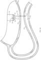
FIGS. 1A-1G provide perspective views of a system in a delivery (FIG. 1A ) and deployed (FIGS. 1B-1G ) configurations, according to embodiments of the present disclosure. -
FIGS. 2A-2E provide perspective views of a system in a delivery (FIG. 2A ) and deployed (FIGS. 2B-2E ) configurations, according to embodiments of the present disclosure. -
FIGS. 3A-3C provide perspective views of a system in a delivery (FIGS. 3A-3B ) and deployed (FIG. 3C ) configuration, according to one embodiment of the present disclosure. -
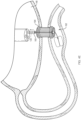
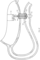
FIGS. 4A-4F provide perspective views of a stent deployment procedure using a system, according to one embodiment of the present disclosure. -
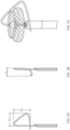
FIGS. 5A-5C provide perspective views of a stent deployment using the system ofFIG. 2E , according to one embodiment of the present disclosure. - The present disclosure is not limited to the particular embodiments described. The terminology used herein is for the purpose of describing particular embodiments only, and is not intended to be limiting beyond the scope of the appended claims. Unless otherwise defined, all technical terms used herein have the same meaning as commonly understood by one of ordinary skill in the art to which the disclosure belongs.
- Although embodiments of the present disclosure are described with specific reference to certain procedures, such as a gastrojejunostomy procedure, the systems and methods described herein may be used to position a fluid conduit between a variety of adjacent tissue walls, organs, vessels and/or body lumens.
- As used herein, the singular forms "a," "an," and "the" are intended to include the plural forms as well, unless the context clearly indicates otherwise. It will be further understood that the terms "comprises" and/or "comprising," or "includes" and/or "including" when used herein, specify the presence of stated features, regions, steps elements and/or components, but do not preclude the presence or addition of one or more other features, regions, integers, steps, operations, elements, components and/or groups thereof.
- As used herein, the term "distal" refers to the end farthest away from the medical professional when introducing a device into a patient, while the term "proximal" refers to the end closest to the medical professional when introducing a device into a patient.
- In various of the embodiments described here and in other embodiments, the present disclosure relates to a system which prevents or minimizes movement between tissue walls during a transmural medical procedure in which a direct visual image and/or control of the distal tissue wall is difficult or not available.
- Referring to
FIG. 1A , in one embodiment, asystem 100 of the present disclosure may include a tissue-penetrating element 110 (e.g., needle, etc.) comprising a proximal end (not shown), a sharpeneddistal end 114 and alumen 116 extending therebetween. An elongate member 120 (e.g., rail, guidewire, etc.) comprising a proximal end (not shown) and adistal end 124 may be slidably disposed within thelumen 116 of the tissue-penetratingelement 110. Adistal portion 125 of theelongate member 120 may be split (e.g., divided) along a longitudinal axis thereof to define first andsecond splines second splines elongate member 120 when disposed within thelumen 116 of thetissue penetrating element 110. At least thedistal portion 125 of theelongate member 120 may include a variety of shape memory materials as are known in the art (e.g., metals, alloys, polymers, and the like), configured to move between a first configuration when disposed withinlumen 116 of the tissue-penetratingelement 110, and a second configuration when disposed distally beyond the sharpeneddistal end 114 of the tissue-penetratingelement 110. Thedistal portion 125 of theelongate member 120 is not limited to two splines, but may include any number of splines (e.g., three or more splines). - Referring to
FIG. 1B , in one embodiment, the first andsecond splines elongate member 120 to form a "T-shape" when in the second configuration. Referring toFIG. 1C , in one embodiment, the first andsecond splines elongate member 120 to form a "Y-shape" when in the second configuration. Referring toFIG. 1D , in one embodiment, the first andsecond splines elongate member 120 to form a "W-shape" when in the second configuration. Referring toFIG. 1E , in one embodiment, the first andsecond splines elongate member 120 to form opposed substantially spherical (e.g., circular) shapes when in the second configuration. Referring toFIG. 1F , in one embodiment, the first andsecond splines elongate member 120 to form opposed substantially oblong (e.g., elliptical, elongate sphere, etc.) shapes when in the second configuration. Referring toFIG. 1G , in one embodiment, the first andsecond splines distal portions 125 of theelongate members 120 are depicted as forming substantially symmetrical structures, in various embodiments the first andsecond splines FIGS. 1B-1G , or other configurations not depicted. In various embodiments, when in the second configuration, the first andsecond splines - Referring to
FIG. 2A , in one embodiment, asystem 200 of the present disclosure may include a tissue-penetrating element 210 (e.g., needle, etc.) comprising a proximal end (not shown), a sharpeneddistal end 214 and alumen 216 extending therebetween. An elongate member 220 (e.g., rail, guidewire, etc.) comprising a proximal end (not shown) and adistal end 224 may be slidably disposed within thelumen 216 of the tissue-penetratingelement 210. At least thedistal portion 225 of theelongate member 220 may include a variety of shape memory materials as are known in the art (e.g., metals, alloys, polymers, and the like), configured to move between a first configuration when disposed withinlumen 216 of the tissue-penetratingelement 210, and a second configuration when disposed (advanced) distally beyond the sharpeneddistal end 214 of the tissue-penetratingelement 210. Referring toFIG. 2B , in one embodiment, thedistal portion 225 of theelongate member 220 may form a "loop" or "hoop" when in the second configuration. Referring toFIG. 2C , in one embodiment, thedistal portion 225 of theelongate member 220 may bend approximately 180 degrees relative to the longitudinal axis of theelongate member 220 to form a "reverse coil" or "reverse spiral" around a portion of theelongate member 220 when in the second configuration. Referring toFIG. 2D , in one embodiment, thedistal portion 225 of theelongate member 220 may form a "figure-eight," lasso," or "cork screw" shape when in the second configuration. Referring toFIG. 2E , in one embodiment, thedistal portion 225 of theelongate member 220 may bend to form a "cross-bar" that extends across the longitudinal axis of theelongate member 220 when in the second configuration. - The various second configurations of the
distal portions elongate member second prongs FIGS. 1B-1D may partially penetrate/embed within the distal tissue wall. A portion of thesplines FIGS. 1B-1G , or thedistal portion 225 of theelongate member 220 ofFIGS. 2B-2E , may include one or more hooks, barbs, prongs, etc. to provide enhanced friction against an inner wall of the distal tissue. In various embodiments, thesplines distal portion 225 of theelongate member 220 may provide a gradual increase in retention pressure when theelongate member splines FIGS. 1B-1D may include a sharpened edge configured to enlarge or expand the puncture hole created by the sharpeneddistal end 114 of the tissue-penetratingelement 110 within the first and/or second tissue walls. One, or both, of the spherical or oblong shapes ofFIGS. 1E-1G , respectively, may deflect (e.g., bend, splay, etc.) away from the longitudinal axis of theelongate member 120 to provide retention pressure across a larger surface area of the distal tissue. - Referring to
FIGS. 3A-3C , in one embodiment, asystem 300 of the present disclosure may include a tissue-penetrating element 310 (e.g., needle, etc.) comprising a proximal end (not shown), a sharpeneddistal end 314 and alumen 316 extending therebetween. Anelongate member 320 may be slidably disposed within thelumen 316 of the tissue-penetratingelement 310. Theelongate member 320 may include acontrol rod 322 slidably disposed within asheath 326. Adistal end 324 of thecontrol rod 322 may be attached to adistal end 327 of thesheath 326. Adistal portion 325 of thesheath 326 may include one ormore slits 329 formed therein, and be configured to move between a first configuration when disposed withinlumen 316 of the tissue-penetrating element 310 (FIG. 3A ), and a second configuration when disposed distally beyond the sharpeneddistal end 314 of the tissue-penetrating element 310 (FIG. 3C ). - For example, at least the
distal portion 325 of thesheath 326 may include a variety of materials, including, but not limited to shape memory materials, e.g., nitinol, polyether ether ketone (PEEK), etc., into which the one ormore slits 329 are formed using, e.g., laser cutting. Theelongate member 320 may be advanced through thelumen 316 of the tissue-penetratingelement 320 by distally advancing the control rod 322 (FIG. 3B ). In one embodiment, thedistal portion 325 of thesheath 326 may move to the second configuration by distally advancing thesheath 326 over/along thecontrol rod 322. Alternatively, thedistal portion 325 of thesheath 326 may move to the second configuration by proximally retracting thecontrol rod 322 through/within the sheath 326 (FIG. 3C ). In either embodiment, the one ormore slits 329 may allow thedistal portion 325 to form a "basket" that includes a series of arms or petals configured to engage the distal tissue wall. In one embodiment, thedistal portion 325 may include one or more hooks, barbs, prongs, etc. for enhanced friction against the distal tissue wall. AlthoughFIGS. 3A-3C depict an embodiment in which thedistal portion 325 includes 5 slits configured to form 5 arms or petals when in the second configuration, in various embodiments, the distal portion may include any number of slits configured to form a variety of second configurations. - In one embodiment, the
elongate members element tissue penetrating elements elongate members distal portion elongate member lumen distal end element - In one embodiment, a
system FIG. 4A , in use and by way of example, anultrasound endoscope 130 may be advanced through the esophagus into a first body lumen 140 (e.g., the stomach). Thedistal end 132 of theendoscope 130 may include acamera 137,light source 138 andultrasound transducer 139. Using the direct view (e.g., thelight source 138 and camera 137) thedistal end 132 of theendoscope 130 may be positioned adjacent to a tissue wall 142 (e.g., proximal tissue wall) of thefirst body lumen 140 which is in the vicinity of the tissue wall 152 (e.g., distal tissue wall) of a second body lumen 150 (e.g., the duodenum or jejunum). Thesecond body lumen 150 may then be imaged through thefirst tissue wall 142 by switching theendoscope 130 from the direct view to an ultrasound view (e.g., turning off thelight source 138 and turning on the ultrasound transducer 139). Thesystem 100 may then be advanced through the workingchannel 136 of theendoscope 130 such that the sharpeneddistal end 114 of the tissue-penetratingelement 110 penetrates the first andsecond tissue walls second body lumen 150. - Referring to
FIG. 4B , theelongate member 120 may be distally advanced beyond the sharpened distal end of the tissue-penetrating element such that thedistal portion 125 moves to the second configuration within thesecond body lumen 150. The tissue-penetrating element may then be removed along/over the elongate member 120 (e.g., proximally withdrawn) through the workingchannel 136 of theendoscope 130. Theelongate member 120 may then be proximally retracted to place thedistal portion 125 in contact with an inner portion of the seconddistal tissue wall 152, and with sufficient force to minimize or prevent (e.g., anchor) movement of thedistal tissue wall 162 relative to theproximal tissue wall 152. - Referring to
FIG. 4C , with the proximal anddistal tissue walls stent delivery system 160 with astent 162 loaded thereon may be advanced through the workingchannel 136 of theendoscope 130. Thestent delivery system 160 may include alumen 166 configured to slide over/along theelongate member 120. The distal end of thestent delivery system 160 may include a cutting element, e.g., electrocautery surface, configured to create opposed openings (e.g., holes) through the first andsecond tissue walls distal portion 125 of theelongate member 120 may provide a firm/secure platform against which the electrocautery surface of thestent delivery system 160 may press when forming the opposed openings. Thedistal portion 125 may provide the additional benefit of establishing separation between the opposite tissue wall of thesecond body lumen 150 and the stent delivery system to prevent unintentional cutting by the cutting element. In one embodiment, one (or both) of the oblong portions of thedistal portion 125 may deflect away from the longitudinal axis of theelongate member 120 to provide retention pressure across a larger surface area of the distal tissue wall. In addition, or alternatively, the ability of the distal portion(s) 125 to deflect away from the longitudinal axis of theelongate member 120 may provide a space to allow: 1) the cutting element of thedelivery system 160 to fully penetrate thesecond body lumen 150, 2) unhindered deployment of thedistal flange 166 of stent 162 (FIG. 4D ), and/or 3) introduction of an additional cutting element to further dilate (e.g., enlarge) the tissue opening without imparting excessive force on the opposite tissue wall of thesecond body lumen 150. In addition, the oblong shape may provide a degree of flexibility to thedistal portion 125, such that thestent delivery system 160 may be advanced a sufficient distance into thesecond body lumen 150 to deploy the distal flange without further pushing thedistal portion 125 against the opposite tissue wall. Thedistal portion 125 of theelongate member 120 may include a soft and/or compliant surface or coating to prevent trauma to the opposite tissue wall in the event contact therebetween occurs. - Referring to
FIG. 4D , an outer portion of thestent delivery system 160 may then be proximally retracted over theinner lumen 166,elongate member 120 andstent 162 to deploy the distal flange 165 of astent 162 within thesecond body lumen 150. Referring toFIG. 4E , the outer portion of thestent delivery system 160 may be further retracted over theinner lumen 166, theelongate member 120 and thestent 162 to deploy theproximal flange 164 of thestent 162 within thefirst body lumen 140. Referring toFIG. 4F , with the proximal anddistal flanges 164, 165 properly deployed within the first andsecond body lumens elongate member 120 may be proximally retracted with sufficient force such that thedistal portion 125 moves from the second configuration to the first configuration for removal through thelumen 166 of the stent delivery system. Theendoscope 130,stent delivery system 160 andelongate member 120 may then be removed from the patient. The stent configuration depicted inFIGS. 4D-4F is provided by way of non-limiting example, and may include a variety of different shapes, configurations, orientations, dimensions and/or materials as required to provide a flow pathway between adjacent tissue walls. In addition, an outer and/or inner surface of the stent may be fully or partially covered (e.g., across the saddle region between the proximal and distal flanges) to prevent fluid leakage between the tissue walls. AlthoughFIGS. 4E-4F depict a gap between the tissue walls of the first andsecond body lumens - Although the
systems elongate member distal portion stent delivery system 160 for deployment of the distal flange within thesecond body lumen 150. - Referring to
FIGS. 5A-5C , in one embodiment, thedistal portion 225 of theelongate member 220 ofFIG. 2E may include a first dimension D1 (e.g., a width), a second dimension D2 (e.g., a height) and a third dimension D3 (e.g., an elevation) relative to the longitudinal axis of theelongate member 220. By way of non-limiting example, the first dimension D1 may be approximately 2.54 cm (1.00 inches), the second dimension D2 may be approximately 1.98 cm (0.78 inches) and the third dimension D3 may be approximately 0.84 cm (0.33 inches). In various embodiments, the first, second and third dimensions D1-D3 of thedistal portion 225 may provide a space within which the distal flange 165 of astent 162 may be deployed (e.g., within a second body lumen, as outlined above), while thedistal portion 225 of the elongate member maintains contact with the tissue wall of the second body lumen throughout the stent deployment procedure. - In various embodiments, the
elongate members elongate members - The medical devices of the present disclosure are not limited to endoscopes, and may include a variety of medical devices for accessing body passageways, including, for example, catheters, bronchoscopes, ureteroscopes, duodenoscopes, colonoscopes, arthroscopes, cystoscopes, hysteroscopes, and the like. Finally, although the embodiments of the present disclosure have been described in use with an endoscope, the systems of the present disclosure may be positioned within the patient in the absence of an accompanying medical device.
- All of the devices and/or methods disclosed and claimed herein can be made and executed without undue experimentation in light of the present disclosure. While the devices and methods of this disclosure have been described in terms of preferred embodiments, it may be apparent to those of skill in the art that variations can be applied to the devices and/or methods and in the steps or in the sequence of steps of the method described herein without departing from the scope of the disclosure. All such similar substitutes and modifications apparent to those skilled in the art are deemed to be within the scope of the disclosure, with the scope of the invention being as defined by the appended claims.
Claims (11)
- An endoscope comprising:a working channel,a stent delivery system (160) configured to be advanced through the working channel and comprising:a stent (162) loaded on the stent delivery system (160),a proximal end,a distal end including a cutting element configured to create openings through tissue walls, anda lumen (166) extending therebetween; andthe endoscope further comprising an elongate member (120) slidably disposed within the lumen (166), wherein a distal portion (125) of the elongate member (120) is configured to move between a first configuration when disposed within the lumen (166), and a second configuration when disposed distally beyond the distal end,wherein the stent delivery system (160) comprises an outer portion configured to be proximally retracted over the inner lumen (166), elongate member (120) and stent (162) to deploy at least a distal flange (164) of the stent (162),characterized in that,the distal portion (125) of the elongate member (120) includes a first dimension (D1), a second dimension (D2) and a third dimension (D3) relative to a longitudinal axis of the elongated member providing a space within which the distal flange (165) of the stent (162) is deployed.
- The endoscope of claim 1, wherein the distal portion (125) of the elongate member (120) is substantially linear in the first configuration.
- The endoscope of claim 1 or claim 2, wherein the distal portion (125) of the elongate member (120) is substantially non-linear in the second configuration.
- The endoscope of any of claims 1-3, wherein the second configuration is selected from the group consisting of a loop, spiral and figure-eight shape.
- The endoscope of any of claims 1-3, wherein the distal portion is split along a longitudinal axis of the elongate member to define first and second splines (125a, 125b).
- The endoscope of claim 5, wherein the first and second splines (125a, 125b) are co-linear with the elongate member in the first configuration.
- The endoscope of claim 5, wherein the first and second splines (125a, 125b) form a Y-shape in the second configuration.
- The endoscope of claim 5, wherein the first and second splines (125a, 125b) form a T-shape in the second configuration.
- The endoscope of claim 5, wherein the first and second splines (125a, 125b) form a W-shape in the second configuration.
- The endoscope of claim 5, wherein the first and second splines (125a, 125b) form spherical structures in the second configuration.
- The endoscope of claim 5, wherein the first and second splines (125a, 125b) form oblong structures in the second configuration.
Priority Applications (1)
| Application Number | Priority Date | Filing Date | Title |
|---|---|---|---|
| EP25163927.4A EP4591914A3 (en) | 2017-03-27 | 2018-03-26 | Systems to effect movement of tissue structures |
Applications Claiming Priority (2)
| Application Number | Priority Date | Filing Date | Title |
|---|---|---|---|
| US201762476995P | 2017-03-27 | 2017-03-27 | |
| PCT/US2018/024341 WO2018183191A1 (en) | 2017-03-27 | 2018-03-26 | Systems to effect movement of tissue structures |
Related Child Applications (2)
| Application Number | Title | Priority Date | Filing Date |
|---|---|---|---|
| EP25163927.4A Division-Into EP4591914A3 (en) | 2017-03-27 | 2018-03-26 | Systems to effect movement of tissue structures |
| EP25163927.4A Division EP4591914A3 (en) | 2017-03-27 | 2018-03-26 | Systems to effect movement of tissue structures |
Publications (2)
| Publication Number | Publication Date |
|---|---|
| EP3551086A1 EP3551086A1 (en) | 2019-10-16 |
| EP3551086B1 true EP3551086B1 (en) | 2025-05-14 |
Family
ID=62002402
Family Applications (2)
| Application Number | Title | Priority Date | Filing Date |
|---|---|---|---|
| EP18718271.2A Active EP3551086B1 (en) | 2017-03-27 | 2018-03-26 | Systems to effect movement of tissue structures |
| EP25163927.4A Pending EP4591914A3 (en) | 2017-03-27 | 2018-03-26 | Systems to effect movement of tissue structures |
Family Applications After (1)
| Application Number | Title | Priority Date | Filing Date |
|---|---|---|---|
| EP25163927.4A Pending EP4591914A3 (en) | 2017-03-27 | 2018-03-26 | Systems to effect movement of tissue structures |
Country Status (5)
| Country | Link |
|---|---|
| US (3) | US10912566B2 (en) |
| EP (2) | EP3551086B1 (en) |
| JP (1) | JP6845337B2 (en) |
| CN (2) | CN110461249B (en) |
| WO (1) | WO2018183191A1 (en) |
Families Citing this family (13)
| Publication number | Priority date | Publication date | Assignee | Title |
|---|---|---|---|---|
| WO2019046352A1 (en) * | 2017-08-30 | 2019-03-07 | Sanford Health | Anchoring guide wire and methods for use thereof |
| EP3914164B1 (en) * | 2019-01-22 | 2025-11-26 | Mayo Foundation for Medical Education and Research | Single anastomosis gastrointestinal tract bypass endoscopic systems |
| CN114728131B (en) | 2019-12-06 | 2025-06-06 | 波士顿科学国际有限公司 | Endoscopic ultrasound-guided needle |
| EP4084667A1 (en) | 2019-12-30 | 2022-11-09 | Boston Scientific Scimed, Inc. | Devices for locating a body lumen |
| US11903857B2 (en) | 2020-01-31 | 2024-02-20 | Boston Scientific Scimed, Inc. | Atraumatic delivery system |
| US20220096253A1 (en) * | 2020-09-25 | 2022-03-31 | Boston Scientific Scimed, Inc. | Adjustable lumen apposing stent |
| US20220096198A1 (en) | 2020-09-28 | 2022-03-31 | Boston Scientific Scimed, Inc. | Devices, systems, and methods for locating a body lumen |
| CN116897021A (en) * | 2020-12-21 | 2023-10-17 | 波士顿科学国际有限公司 | Devices, systems and methods for anchoring tissue |
| KR20240005947A (en) * | 2021-05-10 | 2024-01-12 | 보스톤 싸이엔티픽 싸이메드 인코포레이티드 | Anastomosis devices, systems and methods |
| EP4340786A1 (en) | 2021-05-19 | 2024-03-27 | Boston Scientific Scimed Inc. | Devices, systems, and methods for adjusting a passage through an implantable device |
| US20230233349A1 (en) * | 2022-01-21 | 2023-07-27 | Covidien Lp | Apparatuses for stent delivery and positioning for transluminal application |
| KR20240145027A (en) | 2022-02-11 | 2024-10-04 | 보스톤 싸이엔티픽 싸이메드 인코포레이티드 | Wireless device, system and method for endoscope positioning |
| WO2025207929A1 (en) * | 2024-03-28 | 2025-10-02 | Boston Scientific Scimed, Inc. | Medical systems for providing traction to tissue |
Citations (1)
| Publication number | Priority date | Publication date | Assignee | Title |
|---|---|---|---|---|
| US20050192654A1 (en) * | 2004-01-30 | 2005-09-01 | Nmt Medical, Inc. | Welding systems useful for closure of cardiac openings |
Family Cites Families (23)
| Publication number | Priority date | Publication date | Assignee | Title |
|---|---|---|---|---|
| US6092526A (en) * | 1997-06-19 | 2000-07-25 | Scimed Life Systems, Inc. | Percutaneous chamber-to-artery bypass |
| US20040122456A1 (en) * | 2002-12-11 | 2004-06-24 | Saadat Vahid C. | Methods and apparatus for gastric reduction |
| US20040073237A1 (en) * | 2002-10-08 | 2004-04-15 | Leinsing Karl R. | Surgical fastener and delivery system |
| US8328710B2 (en) * | 2002-11-06 | 2012-12-11 | Senorx, Inc. | Temporary catheter for biopsy site tissue fixation |
| JP4731471B2 (en) * | 2003-04-16 | 2011-07-27 | ジェネシス・テクノロジーズ・エルエルシー | Medical devices and methods |
| US7361180B2 (en) | 2004-05-07 | 2008-04-22 | Usgi Medical, Inc. | Apparatus for manipulating and securing tissue |
| EP1791483B1 (en) * | 2004-08-05 | 2017-04-19 | Covidien LP | Apparatus for coagulating and/or constricting hollow anatomical structures |
| US8926633B2 (en) * | 2005-06-24 | 2015-01-06 | Abbott Laboratories | Apparatus and method for delivering a closure element |
| US7850686B2 (en) * | 2006-03-30 | 2010-12-14 | Ethicon Endo-Surgery, Inc. | Protective needle knife |
| US20080171989A1 (en) * | 2007-01-16 | 2008-07-17 | Bell Stephen G | Trans Urinary Bladder Access Device and Method |
| US20090143760A1 (en) * | 2007-11-30 | 2009-06-04 | Jacques Van Dam | Methods, Devices, Kits and Systems for Defunctionalizing the Gallbladder |
| US8162958B2 (en) * | 2008-07-11 | 2012-04-24 | Olympus Medical Systems Corp. | Tissue fastening tool and applicator for indwelling the same within body, and tissue fastening method through natural orifice |
| US9226772B2 (en) * | 2009-01-30 | 2016-01-05 | Ethicon Endo-Surgery, Inc. | Surgical device |
| US20110137394A1 (en) * | 2009-05-29 | 2011-06-09 | Xlumena, Inc. | Methods and systems for penetrating adjacent tissue layers |
| US20100268029A1 (en) * | 2009-04-21 | 2010-10-21 | Xlumena, Inc. | Methods and apparatus for advancing a device from one body lumen to another |
| EP2434961B1 (en) * | 2009-05-29 | 2015-01-14 | Xlumena, Inc. | Apparatus and method for deploying stent across adjacent tissue layers |
| BR112014007686A2 (en) * | 2011-09-30 | 2017-04-18 | Bioventrix Inc | method and system for heart treatment within the patient |
| US9883855B2 (en) | 2012-01-25 | 2018-02-06 | St. Jude Medical, Llc | Apparatus and method for heart valve repair |
| US20130211415A1 (en) | 2012-02-09 | 2013-08-15 | Boston Scientific Scimed, Inc. | Steerable tissue manipulation medical devices and related methods of use |
| US9033917B2 (en) * | 2012-08-15 | 2015-05-19 | Abbott Cardiovascular Systems Inc. | Needle catheter for delivery of agents directly into vessel wall |
| US10376674B2 (en) * | 2014-09-15 | 2019-08-13 | Ethicon, Inc. | System and method for targeted delivery of therapeutic agents to tissue |
| EP3232953B1 (en) * | 2014-12-16 | 2023-04-05 | Intervene, Inc. | Intravascular devices for the controlled dissection of body lumens |
| US10111715B2 (en) * | 2015-05-11 | 2018-10-30 | Veran Medical Technologies, Inc. | Adjustable length medical instrument assembly with localization elements for tracking medical instrument extension |
-
2018
- 2018-03-26 EP EP18718271.2A patent/EP3551086B1/en active Active
- 2018-03-26 CN CN201880021646.4A patent/CN110461249B/en active Active
- 2018-03-26 JP JP2019539925A patent/JP6845337B2/en active Active
- 2018-03-26 WO PCT/US2018/024341 patent/WO2018183191A1/en not_active Ceased
- 2018-03-26 CN CN202310012958.1A patent/CN116369997B/en active Active
- 2018-03-26 EP EP25163927.4A patent/EP4591914A3/en active Pending
- 2018-03-26 US US15/935,969 patent/US10912566B2/en active Active
-
2021
- 2021-01-06 US US17/142,659 patent/US12161337B2/en active Active
-
2024
- 2024-11-05 US US18/937,563 patent/US20250057533A1/en active Pending
Patent Citations (1)
| Publication number | Priority date | Publication date | Assignee | Title |
|---|---|---|---|---|
| US20050192654A1 (en) * | 2004-01-30 | 2005-09-01 | Nmt Medical, Inc. | Welding systems useful for closure of cardiac openings |
Also Published As
| Publication number | Publication date |
|---|---|
| JP6845337B2 (en) | 2021-03-17 |
| US12161337B2 (en) | 2024-12-10 |
| US20250057533A1 (en) | 2025-02-20 |
| WO2018183191A1 (en) | 2018-10-04 |
| JP2020503984A (en) | 2020-02-06 |
| CN110461249A (en) | 2019-11-15 |
| EP3551086A1 (en) | 2019-10-16 |
| CN116369997B (en) | 2026-03-24 |
| US20180271530A1 (en) | 2018-09-27 |
| EP4591914A3 (en) | 2025-10-22 |
| CN110461249B (en) | 2023-01-31 |
| EP4591914A2 (en) | 2025-07-30 |
| US10912566B2 (en) | 2021-02-09 |
| US20210145442A1 (en) | 2021-05-20 |
| CN116369997A (en) | 2023-07-04 |
Similar Documents
| Publication | Publication Date | Title |
|---|---|---|
| US20250057533A1 (en) | Systems and methods to effect movement of tissue structures | |
| US8475476B2 (en) | System and method for accessing a body cavity | |
| US11534060B2 (en) | Devices and methods for tissue retraction | |
| EP2421451B1 (en) | System for delivering an expanding trocar through a sheath | |
| JP5345297B2 (en) | Flexible endoscope safety needle | |
| US10390806B2 (en) | Devices, systems, and methods for obtaining a tissue sample using a biopsy tool | |
| US20140357946A1 (en) | Tissue spreader for accessing papilla, and related methods of use | |
| US20190254674A1 (en) | Apparatus and method for deploying stent across adjacent tissue layers | |
| EP1854421A2 (en) | Endoscopic translumenal surgical systems | |
| US20070260121A1 (en) | Endoscopic Translumenal Surgical Systems | |
| US20070260117A1 (en) | Endoscopic Translumenal Surgical Systems | |
| JP7104640B2 (en) | Self-fixing catheter and how to use it | |
| US20090287165A1 (en) | Cannulated Device with Atraumatic Tip for Delivering Local Depot to a Joint Space and Methods of Use Thereof | |
| EA027149B1 (en) | Steerable deflectors and methods of using same | |
| EP3808316B1 (en) | Hot-puncture stent implantation device | |
| US11712237B1 (en) | Anatomical tissue anchor and related methods | |
| WO2024019794A1 (en) | Anatomical tissue anchor and related methods | |
| WO2025019771A1 (en) | Devices, systems and methods for percutaneously accessing and securing internal organs or other target tissue within a patient |
Legal Events
| Date | Code | Title | Description |
|---|---|---|---|
| STAA | Information on the status of an ep patent application or granted ep patent |
Free format text: STATUS: UNKNOWN |
|
| STAA | Information on the status of an ep patent application or granted ep patent |
Free format text: STATUS: THE INTERNATIONAL PUBLICATION HAS BEEN MADE |
|
| PUAI | Public reference made under article 153(3) epc to a published international application that has entered the european phase |
Free format text: ORIGINAL CODE: 0009012 |
|
| STAA | Information on the status of an ep patent application or granted ep patent |
Free format text: STATUS: REQUEST FOR EXAMINATION WAS MADE |
|
| 17P | Request for examination filed |
Effective date: 20190712 |
|
| AK | Designated contracting states |
Kind code of ref document: A1 Designated state(s): AL AT BE BG CH CY CZ DE DK EE ES FI FR GB GR HR HU IE IS IT LI LT LU LV MC MK MT NL NO PL PT RO RS SE SI SK SM TR |
|
| AX | Request for extension of the european patent |
Extension state: BA ME |
|
| DAV | Request for validation of the european patent (deleted) | ||
| DAX | Request for extension of the european patent (deleted) | ||
| STAA | Information on the status of an ep patent application or granted ep patent |
Free format text: STATUS: EXAMINATION IS IN PROGRESS |
|
| 17Q | First examination report despatched |
Effective date: 20230203 |
|
| GRAP | Despatch of communication of intention to grant a patent |
Free format text: ORIGINAL CODE: EPIDOSNIGR1 |
|
| STAA | Information on the status of an ep patent application or granted ep patent |
Free format text: STATUS: GRANT OF PATENT IS INTENDED |
|
| RIC1 | Information provided on ipc code assigned before grant |
Ipc: A61F 2/04 20130101ALN20241126BHEP Ipc: A61F 2/90 20130101ALN20241126BHEP Ipc: A61F 2/06 20130101ALN20241126BHEP Ipc: A61M 25/09 20060101ALI20241126BHEP Ipc: A61B 17/22 20060101ALI20241126BHEP Ipc: A61B 17/08 20060101ALI20241126BHEP Ipc: A61B 17/00 20060101ALI20241126BHEP Ipc: A61M 25/04 20060101ALI20241126BHEP Ipc: A61F 2/966 20130101ALI20241126BHEP Ipc: A61B 17/34 20060101ALI20241126BHEP Ipc: A61B 17/11 20060101ALI20241126BHEP Ipc: A61B 17/06 20060101AFI20241126BHEP |
|
| INTG | Intention to grant announced |
Effective date: 20241210 |
|
| GRAS | Grant fee paid |
Free format text: ORIGINAL CODE: EPIDOSNIGR3 |
|
| GRAA | (expected) grant |
Free format text: ORIGINAL CODE: 0009210 |
|
| STAA | Information on the status of an ep patent application or granted ep patent |
Free format text: STATUS: THE PATENT HAS BEEN GRANTED |
|
| RAP3 | Party data changed (applicant data changed or rights of an application transferred) |
Owner name: BOSTON SCIENTIFIC SCIMED, INC. |
|
| AK | Designated contracting states |
Kind code of ref document: B1 Designated state(s): AL AT BE BG CH CY CZ DE DK EE ES FI FR GB GR HR HU IE IS IT LI LT LU LV MC MK MT NL NO PL PT RO RS SE SI SK SM TR |
|
| REG | Reference to a national code |
Ref country code: GB Ref legal event code: FG4D |
|
| REG | Reference to a national code |
Ref country code: CH Ref legal event code: EP |
|
| REG | Reference to a national code |
Ref country code: DE Ref legal event code: R096 Ref document number: 602018081901 Country of ref document: DE |
|
| REG | Reference to a national code |
Ref country code: IE Ref legal event code: FG4D |
|
| REG | Reference to a national code |
Ref country code: NL Ref legal event code: FP |
|
| PG25 | Lapsed in a contracting state [announced via postgrant information from national office to epo] |
Ref country code: FI Free format text: LAPSE BECAUSE OF FAILURE TO SUBMIT A TRANSLATION OF THE DESCRIPTION OR TO PAY THE FEE WITHIN THE PRESCRIBED TIME-LIMIT Effective date: 20250514 Ref country code: PT Free format text: LAPSE BECAUSE OF FAILURE TO SUBMIT A TRANSLATION OF THE DESCRIPTION OR TO PAY THE FEE WITHIN THE PRESCRIBED TIME-LIMIT Effective date: 20250915 Ref country code: ES Free format text: LAPSE BECAUSE OF FAILURE TO SUBMIT A TRANSLATION OF THE DESCRIPTION OR TO PAY THE FEE WITHIN THE PRESCRIBED TIME-LIMIT Effective date: 20250514 |
|
| REG | Reference to a national code |
Ref country code: LT Ref legal event code: MG9D |
|
| PG25 | Lapsed in a contracting state [announced via postgrant information from national office to epo] |
Ref country code: GR Free format text: LAPSE BECAUSE OF FAILURE TO SUBMIT A TRANSLATION OF THE DESCRIPTION OR TO PAY THE FEE WITHIN THE PRESCRIBED TIME-LIMIT Effective date: 20250815 Ref country code: NO Free format text: LAPSE BECAUSE OF FAILURE TO SUBMIT A TRANSLATION OF THE DESCRIPTION OR TO PAY THE FEE WITHIN THE PRESCRIBED TIME-LIMIT Effective date: 20250814 |
|
| PG25 | Lapsed in a contracting state [announced via postgrant information from national office to epo] |
Ref country code: PL Free format text: LAPSE BECAUSE OF FAILURE TO SUBMIT A TRANSLATION OF THE DESCRIPTION OR TO PAY THE FEE WITHIN THE PRESCRIBED TIME-LIMIT Effective date: 20250514 |
|
| REG | Reference to a national code |
Ref country code: AT Ref legal event code: MK05 Ref document number: 1794140 Country of ref document: AT Kind code of ref document: T Effective date: 20250514 |
|
| PG25 | Lapsed in a contracting state [announced via postgrant information from national office to epo] |
Ref country code: BG Free format text: LAPSE BECAUSE OF FAILURE TO SUBMIT A TRANSLATION OF THE DESCRIPTION OR TO PAY THE FEE WITHIN THE PRESCRIBED TIME-LIMIT Effective date: 20250514 |
|
| PG25 | Lapsed in a contracting state [announced via postgrant information from national office to epo] |
Ref country code: HR Free format text: LAPSE BECAUSE OF FAILURE TO SUBMIT A TRANSLATION OF THE DESCRIPTION OR TO PAY THE FEE WITHIN THE PRESCRIBED TIME-LIMIT Effective date: 20250514 |
|
| PG25 | Lapsed in a contracting state [announced via postgrant information from national office to epo] |
Ref country code: AT Free format text: LAPSE BECAUSE OF FAILURE TO SUBMIT A TRANSLATION OF THE DESCRIPTION OR TO PAY THE FEE WITHIN THE PRESCRIBED TIME-LIMIT Effective date: 20250514 |
|
| PG25 | Lapsed in a contracting state [announced via postgrant information from national office to epo] |
Ref country code: RS Free format text: LAPSE BECAUSE OF FAILURE TO SUBMIT A TRANSLATION OF THE DESCRIPTION OR TO PAY THE FEE WITHIN THE PRESCRIBED TIME-LIMIT Effective date: 20250814 |
|
| PG25 | Lapsed in a contracting state [announced via postgrant information from national office to epo] |
Ref country code: IS Free format text: LAPSE BECAUSE OF FAILURE TO SUBMIT A TRANSLATION OF THE DESCRIPTION OR TO PAY THE FEE WITHIN THE PRESCRIBED TIME-LIMIT Effective date: 20250914 |
|
| PG25 | Lapsed in a contracting state [announced via postgrant information from national office to epo] |
Ref country code: LV Free format text: LAPSE BECAUSE OF FAILURE TO SUBMIT A TRANSLATION OF THE DESCRIPTION OR TO PAY THE FEE WITHIN THE PRESCRIBED TIME-LIMIT Effective date: 20250514 |
|
| PG25 | Lapsed in a contracting state [announced via postgrant information from national office to epo] |
Ref country code: DK Free format text: LAPSE BECAUSE OF FAILURE TO SUBMIT A TRANSLATION OF THE DESCRIPTION OR TO PAY THE FEE WITHIN THE PRESCRIBED TIME-LIMIT Effective date: 20250514 Ref country code: SM Free format text: LAPSE BECAUSE OF FAILURE TO SUBMIT A TRANSLATION OF THE DESCRIPTION OR TO PAY THE FEE WITHIN THE PRESCRIBED TIME-LIMIT Effective date: 20250514 |
|
| PG25 | Lapsed in a contracting state [announced via postgrant information from national office to epo] |
Ref country code: CZ Free format text: LAPSE BECAUSE OF FAILURE TO SUBMIT A TRANSLATION OF THE DESCRIPTION OR TO PAY THE FEE WITHIN THE PRESCRIBED TIME-LIMIT Effective date: 20250514 |
|
| PG25 | Lapsed in a contracting state [announced via postgrant information from national office to epo] |
Ref country code: EE Free format text: LAPSE BECAUSE OF FAILURE TO SUBMIT A TRANSLATION OF THE DESCRIPTION OR TO PAY THE FEE WITHIN THE PRESCRIBED TIME-LIMIT Effective date: 20250514 |
|
| PG25 | Lapsed in a contracting state [announced via postgrant information from national office to epo] |
Ref country code: RO Free format text: LAPSE BECAUSE OF FAILURE TO SUBMIT A TRANSLATION OF THE DESCRIPTION OR TO PAY THE FEE WITHIN THE PRESCRIBED TIME-LIMIT Effective date: 20250514 Ref country code: SK Free format text: LAPSE BECAUSE OF FAILURE TO SUBMIT A TRANSLATION OF THE DESCRIPTION OR TO PAY THE FEE WITHIN THE PRESCRIBED TIME-LIMIT Effective date: 20250514 |
|
| PG25 | Lapsed in a contracting state [announced via postgrant information from national office to epo] |
Ref country code: IT Free format text: LAPSE BECAUSE OF FAILURE TO SUBMIT A TRANSLATION OF THE DESCRIPTION OR TO PAY THE FEE WITHIN THE PRESCRIBED TIME-LIMIT Effective date: 20250514 |
|
| REG | Reference to a national code |
Ref country code: DE Ref legal event code: R097 Ref document number: 602018081901 Country of ref document: DE |
|
| PGFP | Annual fee paid to national office [announced via postgrant information from national office to epo] |
Ref country code: NL Payment date: 20260219 Year of fee payment: 9 |
|
| PLBE | No opposition filed within time limit |
Free format text: ORIGINAL CODE: 0009261 |
|
| STAA | Information on the status of an ep patent application or granted ep patent |
Free format text: STATUS: NO OPPOSITION FILED WITHIN TIME LIMIT |
|
| REG | Reference to a national code |
Ref country code: CH Ref legal event code: L10 Free format text: ST27 STATUS EVENT CODE: U-0-0-L10-L00 (AS PROVIDED BY THE NATIONAL OFFICE) Effective date: 20260325 |
|
| PGFP | Annual fee paid to national office [announced via postgrant information from national office to epo] |
Ref country code: GB Payment date: 20260220 Year of fee payment: 9 |
|
| PGFP | Annual fee paid to national office [announced via postgrant information from national office to epo] |
Ref country code: DE Payment date: 20260219 Year of fee payment: 9 Ref country code: IE Payment date: 20260223 Year of fee payment: 9 |
|
| 26N | No opposition filed |
Effective date: 20260217 |
|
| PG25 | Lapsed in a contracting state [announced via postgrant information from national office to epo] |
Ref country code: LT Free format text: LAPSE BECAUSE OF FAILURE TO SUBMIT A TRANSLATION OF THE DESCRIPTION OR TO PAY THE FEE WITHIN THE PRESCRIBED TIME-LIMIT Effective date: 20250514 |
|
| PG25 | Lapsed in a contracting state [announced via postgrant information from national office to epo] |
Ref country code: SE Free format text: LAPSE BECAUSE OF FAILURE TO SUBMIT A TRANSLATION OF THE DESCRIPTION OR TO PAY THE FEE WITHIN THE PRESCRIBED TIME-LIMIT Effective date: 20250514 |