EP3550922B1 - Method and apparatus for transmitting and receiving random access preambles in a wireless communication system - Google Patents
Method and apparatus for transmitting and receiving random access preambles in a wireless communication system Download PDFInfo
- Publication number
- EP3550922B1 EP3550922B1 EP19166854.0A EP19166854A EP3550922B1 EP 3550922 B1 EP3550922 B1 EP 3550922B1 EP 19166854 A EP19166854 A EP 19166854A EP 3550922 B1 EP3550922 B1 EP 3550922B1
- Authority
- EP
- European Patent Office
- Prior art keywords
- preamble
- format
- subcarrier
- random access
- value
- Prior art date
- Legal status (The legal status is an assumption and is not a legal conclusion. Google has not performed a legal analysis and makes no representation as to the accuracy of the status listed.)
- Active
Links
- 238000000034 method Methods 0.000 title claims description 138
- 238000004891 communication Methods 0.000 title claims description 42
- 230000004044 response Effects 0.000 claims description 20
- 210000004027 cell Anatomy 0.000 description 113
- 230000005540 biological transmission Effects 0.000 description 72
- 230000001869 rapid Effects 0.000 description 62
- 230000002776 aggregation Effects 0.000 description 36
- 238000004220 aggregation Methods 0.000 description 36
- 238000010586 diagram Methods 0.000 description 29
- 239000000969 carrier Substances 0.000 description 19
- 230000011664 signaling Effects 0.000 description 19
- 210000004457 myocytus nodalis Anatomy 0.000 description 17
- 230000006870 function Effects 0.000 description 13
- 125000004122 cyclic group Chemical group 0.000 description 10
- 230000015654 memory Effects 0.000 description 10
- 238000013507 mapping Methods 0.000 description 9
- 238000013468 resource allocation Methods 0.000 description 9
- 230000000694 effects Effects 0.000 description 7
- 230000008569 process Effects 0.000 description 7
- 230000008859 change Effects 0.000 description 6
- 238000010295 mobile communication Methods 0.000 description 5
- 238000012545 processing Methods 0.000 description 5
- 238000005516 engineering process Methods 0.000 description 4
- 230000001419 dependent effect Effects 0.000 description 3
- 101100127891 Caenorhabditis elegans let-4 gene Proteins 0.000 description 2
- 238000001994 activation Methods 0.000 description 2
- 230000001174 ascending effect Effects 0.000 description 2
- 230000004069 differentiation Effects 0.000 description 2
- 230000000977 initiatory effect Effects 0.000 description 2
- 101150065184 sym-2 gene Proteins 0.000 description 2
- 238000012546 transfer Methods 0.000 description 2
- 101001056707 Homo sapiens Proepiregulin Proteins 0.000 description 1
- 101100465000 Mus musculus Prag1 gene Proteins 0.000 description 1
- 102100025498 Proepiregulin Human genes 0.000 description 1
- 101150014328 RAN2 gene Proteins 0.000 description 1
- 101150004636 SYM1 gene Proteins 0.000 description 1
- 230000004308 accommodation Effects 0.000 description 1
- 230000004913 activation Effects 0.000 description 1
- 238000003491 array Methods 0.000 description 1
- 230000001413 cellular effect Effects 0.000 description 1
- 238000012937 correction Methods 0.000 description 1
- 230000007423 decrease Effects 0.000 description 1
- 238000013461 design Methods 0.000 description 1
- 230000009977 dual effect Effects 0.000 description 1
- 239000002360 explosive Substances 0.000 description 1
- 230000007274 generation of a signal involved in cell-cell signaling Effects 0.000 description 1
- 230000007774 longterm Effects 0.000 description 1
- 238000005259 measurement Methods 0.000 description 1
- 238000012544 monitoring process Methods 0.000 description 1
- 230000008450 motivation Effects 0.000 description 1
- 230000006855 networking Effects 0.000 description 1
- 230000003252 repetitive effect Effects 0.000 description 1
- 238000001228 spectrum Methods 0.000 description 1
- 230000001960 triggered effect Effects 0.000 description 1
Images


Classifications
-
- H—ELECTRICITY
- H04—ELECTRIC COMMUNICATION TECHNIQUE
- H04L—TRANSMISSION OF DIGITAL INFORMATION, e.g. TELEGRAPHIC COMMUNICATION
- H04L27/00—Modulated-carrier systems
- H04L27/26—Systems using multi-frequency codes
- H04L27/2601—Multicarrier modulation systems
- H04L27/2647—Arrangements specific to the receiver only
- H04L27/2655—Synchronisation arrangements
- H04L27/2689—Link with other circuits, i.e. special connections between synchronisation arrangements and other circuits for achieving synchronisation
- H04L27/2692—Link with other circuits, i.e. special connections between synchronisation arrangements and other circuits for achieving synchronisation with preamble design, i.e. with negotiation of the synchronisation sequence with transmitter or sequence linked to the algorithm used at the receiver
-
- H—ELECTRICITY
- H04—ELECTRIC COMMUNICATION TECHNIQUE
- H04W—WIRELESS COMMUNICATION NETWORKS
- H04W74/00—Wireless channel access, e.g. scheduled or random access
- H04W74/08—Non-scheduled or contention based access, e.g. random access, ALOHA, CSMA [Carrier Sense Multiple Access]
- H04W74/0833—Non-scheduled or contention based access, e.g. random access, ALOHA, CSMA [Carrier Sense Multiple Access] using a random access procedure
-
- H—ELECTRICITY
- H04—ELECTRIC COMMUNICATION TECHNIQUE
- H04L—TRANSMISSION OF DIGITAL INFORMATION, e.g. TELEGRAPHIC COMMUNICATION
- H04L27/00—Modulated-carrier systems
- H04L27/26—Systems using multi-frequency codes
- H04L27/2601—Multicarrier modulation systems
- H04L27/2602—Signal structure
-
- H—ELECTRICITY
- H04—ELECTRIC COMMUNICATION TECHNIQUE
- H04L—TRANSMISSION OF DIGITAL INFORMATION, e.g. TELEGRAPHIC COMMUNICATION
- H04L5/00—Arrangements affording multiple use of the transmission path
- H04L5/0001—Arrangements for dividing the transmission path
- H04L5/0003—Two-dimensional division
- H04L5/0005—Time-frequency
- H04L5/0007—Time-frequency the frequencies being orthogonal, e.g. OFDM(A), DMT
- H04L5/001—Time-frequency the frequencies being orthogonal, e.g. OFDM(A), DMT the frequencies being arranged in component carriers
-
- H—ELECTRICITY
- H04—ELECTRIC COMMUNICATION TECHNIQUE
- H04L—TRANSMISSION OF DIGITAL INFORMATION, e.g. TELEGRAPHIC COMMUNICATION
- H04L5/00—Arrangements affording multiple use of the transmission path
- H04L5/003—Arrangements for allocating sub-channels of the transmission path
- H04L5/0053—Allocation of signaling, i.e. of overhead other than pilot signals
- H04L5/0055—Physical resource allocation for ACK/NACK
-
- H—ELECTRICITY
- H04—ELECTRIC COMMUNICATION TECHNIQUE
- H04L—TRANSMISSION OF DIGITAL INFORMATION, e.g. TELEGRAPHIC COMMUNICATION
- H04L5/00—Arrangements affording multiple use of the transmission path
- H04L5/0091—Signaling for the administration of the divided path
-
- H—ELECTRICITY
- H04—ELECTRIC COMMUNICATION TECHNIQUE
- H04W—WIRELESS COMMUNICATION NETWORKS
- H04W74/00—Wireless channel access, e.g. scheduled or random access
- H04W74/002—Transmission of channel access control information
- H04W74/006—Transmission of channel access control information in the downlink, i.e. towards the terminal
-
- H—ELECTRICITY
- H04—ELECTRIC COMMUNICATION TECHNIQUE
- H04W—WIRELESS COMMUNICATION NETWORKS
- H04W74/00—Wireless channel access, e.g. scheduled or random access
- H04W74/002—Transmission of channel access control information
- H04W74/008—Transmission of channel access control information with additional processing of random access related information at receiving side
-
- Y—GENERAL TAGGING OF NEW TECHNOLOGICAL DEVELOPMENTS; GENERAL TAGGING OF CROSS-SECTIONAL TECHNOLOGIES SPANNING OVER SEVERAL SECTIONS OF THE IPC; TECHNICAL SUBJECTS COVERED BY FORMER USPC CROSS-REFERENCE ART COLLECTIONS [XRACs] AND DIGESTS
- Y02—TECHNOLOGIES OR APPLICATIONS FOR MITIGATION OR ADAPTATION AGAINST CLIMATE CHANGE
- Y02D—CLIMATE CHANGE MITIGATION TECHNOLOGIES IN INFORMATION AND COMMUNICATION TECHNOLOGIES [ICT], I.E. INFORMATION AND COMMUNICATION TECHNOLOGIES AIMING AT THE REDUCTION OF THEIR OWN ENERGY USE
- Y02D30/00—Reducing energy consumption in communication networks
- Y02D30/70—Reducing energy consumption in communication networks in wireless communication networks
Definitions
- the present invention relates to a method for transmitting and receiving a random access preamble in a wireless communication system, and more particularly, to a method for transmitting and receiving a random access preamble in a wireless communication system supporting NarrowBand-Internet of Things (NB-IoT) and an apparatus for supporting the same.
- NB-IoT NarrowBand-Internet of Things
- Mobile communication systems have been developed to provide voice services, while guaranteeing user activity.
- Service coverage of mobile communication systems has extended even to data services, as well as voice services, and currently, an explosive increase in traffic has resulted in shortage of resource and user demand for a high speed services, requiring advanced mobile communication systems.
- the requirements of the next-generation mobile communication system may include supporting huge data traffic, a remarkable increase in the transfer rate of each user, the accommodation of a significantly increased number of connection devices, very low end-to-end latency, and high energy efficiency.
- various techniques such as small cell enhancement, dual connectivity, massive Multiple Input Multiple Output (MIMO), in-band full duplex, non-orthogonal multiple access (NOMA), supporting super-wide band, and device networking, have been researched.
- MIMO massive Multiple Input Multiple Output
- NOMA non-orthogonal multiple access
- U.S. patent application publication No. 2016/330766 A1 discusses methods, nodes, a system, and computer storage mediums for non-contention random access.
- U.S. patent application publication No. 2015/282215 A1 discusses random access procedures for machine-type communications.
- This specification proposes a method for transmitting and receiving a random access preamble in a wireless communication system supporting NarrowBand-Internet of Things (NB-IoT).
- NB-IoT NarrowBand-Internet of Things
- this specification proposes a method for transmitting and receiving an existing NPRACH preamble and an enhanced PRACH preamble when the enhanced PRACH preamble is supported in addition to the existing NPRACH preamble.
- this specification proposes a method for distinguishing whether a preamble allocated to a UE is the existing NPRACH preamble or the enhanced PRACH preamble.
- this specification proposes a method for configuring a field of downlink control information (DCI) according to the NPRACH preamble allocated to the UE.
- DCI downlink control information
- this specification proposes a method for determining the number of bits of a field for allocating a subcarrier index according to the NPRACH preamble allocated to the UE.
- a method for transmitting a random access preamble by a user equipment (UE) in a wireless communication system supporting a narrow band-Internet of things (NB-IoT) is provided as set forth in the appended claims.
- NB-IoT narrow band-Internet of things
- a UE configured for transmitting a random access preamble in a wireless communication system supporting a narrow band-Internet of things (NB-IoT) is provided as set forth in the appended claims.
- NB-IoT narrow band-Internet of things
- a UE can recognize whether a preamble allocated for a random access procedure is an existing random access preamble or an enhanced random access preamble.
- a base station has the meaning of a terminal node of a network over which the base station directly communicates with a device.
- a specific operation that is described to be performed by a base station may be performed by an upper node of the base station according to circumstances. That is, it is evident that in a network including a plurality of network nodes including a base station, various operations performed for communication with a device may be performed by the base station or other network nodes other than the base station.
- the base station may be substituted with another term, such as a fixed station, a Node B, an eNB (evolved-NodeB), a Base Transceiver System (BTS), an access point (AP), or), gNB(next generation NB, general NB, gNodeB).
- the device may be fixed or may have mobility and may be substituted with another term, such as User Equipment (UE), a Mobile Station (MS), a User Terminal (UT), a Mobile Subscriber Station (MSS), a Subscriber Station (SS), an Advanced Mobile Station (AMS), a Wireless Terminal (WT), a Machine-Type Communication (MTC) device, a Machine-to-Machine (M2M) device, or a Device-to-Device (D2D) device.
- UE User Equipment
- MS Mobile Station
- UT User Terminal
- MSS Mobile Subscriber Station
- SS Subscriber Station
- AMS Advanced Mobile Station
- WT Wireless Terminal
- MTC Machine-Type Communication
- M2M Machine-to-Machine
- D2D Device-to-Device
- downlink means communication from an eNB to UE
- uplink means communication from UE to an eNB.
- a transmitter may be part of an eNB, and a receiver may be part of UE.
- a transmitter may be part of UE, and a receiver may be part of an eNB.
- CDMA Code Division Multiple Access
- FDMA Frequency Division Multiple Access
- TDMA Time Division Multiple Access
- OFDMA Orthogonal Frequency Division Multiple Access
- SC-FDMA Single Carrier Frequency Division Multiple Access
- NOMA Non-Orthogonal Multiple Access
- CDMA may be implemented using a radio technology, such as Universal Terrestrial Radio Access (UTRA) or CDMA2000.
- TDMA may be implemented using a radio technology, such as Global System for Mobile communications (GSM)/General Packet Radio Service (GPRS)/Enhanced Data rates for GSM Evolution (EDGE).
- GSM Global System for Mobile communications
- GPRS General Packet Radio Service
- EDGE Enhanced Data rates for GSM Evolution
- OFDMA may be implemented using a radio technology, such as Institute of Electrical and Electronics Engineers (IEEE) 802.11 (Wi-Fi), IEEE 802.16 (WiMAX), IEEE 802.20, or Evolved UTRA (E-UTRA).
- UTRA is part of a Universal Mobile Telecommunications System (UMTS).
- 3rd Generation Partnership Project (3GPP) Long Term Evolution (LTE) is part of an Evolved UMTS (E-UMTS) using evolved UMTS Terrestrial Radio Access (E-UTRA), and it adopts OFDMA in downlink and adopts SC-FDMA in uplink.
- LTE-Advanced (LTE-A) is the evolution of 3GPP LTE.
- 5G new radio defines Enhanced Mobile Broadband (eMBB), Massive Machine Type Communications (mMTC), Ultra-Reliable and Low Latency Communications (URLLC), and vehicle-to-everything (V2X) according to a usage scenario.
- eMBB Enhanced Mobile Broadband
- mMTC Massive Machine Type Communications
- URLLC Ultra-Reliable and Low Latency Communications
- V2X vehicle-to-everything
- the 5G NR standard is divided into standalone (SA) and non-standalone (NSA) depending on co-existence between the NR system and the LTE system.
- the 5G NR supports various subcarrier spacings, and supports CP-OFDM in the downlink and CF-OFDM and DFT-s-OFDM (SC-OFDM) in the uplink.
- Embodiments of the present invention may be supported by standard documents disclosed in at least one of wireless access systems IEEE 802, 3GPP, and 3GPP2. That is, steps or portions of the embodiments of the present invention which are not described in order to clearly illustrate the technical features of the present invention may be supported by the documents. Further, all terms disclosed in the document may be described by the standard document.
- eLTE eNB The eLTE eNB is the evolution of an eNB that supports connections to Evolved Packet Core (EPC) and Next Generation Core (NGC).
- EPC Evolved Packet Core
- NGC Next Generation Core
- gNB Node that supports the NR as well as connection to the NGC.
- New RAN Wireless access network that supports the E-UTRA or interacts with the NGC.
- the network slice is a network defined by an operator to provide an optimized solution for a specific market scenario that requires specific requirements with end-to-end coverage.
- the network function is a logic node in a network infrastructure having a well defined external interface and a well defined functional operation.
- NG-C Control plane interface used for an NG reference point between new RAN and the NGC.
- NG-U User plane interface used for an NG3 reference point between the enhanced RAN and the NGC.
- Non-standalone NR Arrangement configuration in which gNB requests an LTE eNB as an anchor for EPC control plane connection or an eLTE eNB as the anchor for the control plane connection to the NGC.
- Non-standalone E-UTRA Arrangement configuration in which the eLTE eNB requires the gNB as the anchor for the control plane connection to the NGC.
- User plane gateway Endpoint of NG-U interface.
- Different numerology Corresponds to one subcarrier spacing in a frequency domain. Different numerology may be defined by scaling reference subcarrier spacing to an integer N.
- NR NR Radio Access or New Radio
- FIG. 1 shows the structure of a radio frame in a wireless communication system to which an embodiment of the present invention may be applied.
- 3GPP LTE/LTE-A support a radio frame structure type 1 which may be applicable to Frequency Division Duplex (FDD) and a radio frame structure which may be applicable to Time Division Duplex (TDD).
- FDD Frequency Division Duplex
- TDD Time Division Duplex
- FIG. 1(a) exemplifies a radio frame structure type 1.
- the type 1 radio frame may be applied to both of full duplex FDD and half duplex FDD.
- a radio frame includes 10 subframes.
- One subframe includes contiguous two slots in the time domain, and subframe i includes slot 2i and slot 2i+1.
- the time required for transmitting a subframe is referred to as a transmission time interval (TTI).
- TTI transmission time interval
- the length of the subframe i may be 1 ms and the length of a slot may be 0.5 ms.
- a UL transmission and a DL transmission I the FDD are distinguished in the frequency domain. Whereas there is no restriction in the full duplex FDD, a UE may not transmit and receive simultaneously in the half duplex FDD operation.
- One slot includes a plurality of Orthogonal Frequency Division Multiplexing (OFDM) symbols in the time domain and includes a plurality of Resource Blocks (RBs) in a frequency domain.
- OFDM symbols are used to represent one symbol period because OFDMA is used in downlink.
- An OFDM symbol may be called one SC-FDMA symbol or symbol period.
- An RB is a resource allocation unit and includes a plurality of contiguous subcarriers in one slot.
- FIG. 1(b) shows frame structure type 2.
- an uplink-downlink configuration is a rule indicating whether uplink and downlink are allocated (or reserved) to all subframes.
- Table 1 shows the uplink-downlink configuration.
- Uplink-Downlink configuration Downlink-to-Uplink Switch-point periodicity Subframe number 0 1 2 3 4 5 6 7 8 9 0 5ms D S U U U D S U U U 1 5ms D S U U D D S U U D 2 5ms D S U D D D S U D D 3 10ms D S U U U D D D D D D 4 10ms D S U U D D D D D D 5 10ms D S U D D D D D D D 6 5ms D S U U U D S U U D S U U D S U U D
- 'D' represents a subframe for a DL transmission
- 'U' represents a subframe for UL transmission
- 'S' represents a special subframe including three types of fields including a Downlink Pilot Time Slot (DwPTS), a Guard Period (GP), and an Uplink Pilot Time Slot (UpPTS).
- DwPTS Downlink Pilot Time Slot
- GP Guard Period
- UpPTS Uplink Pilot Time Slot
- a DwPTS is used for an initial cell search, synchronization or channel estimation in a UE.
- a UpPTS is used for channel estimation in an eNB and for synchronizing a UL transmission synchronization of a UE.
- a GP is duration for removing interference occurred in a UL owing to multi-path delay of a DL signal between a UL and a DL.
- the UL-DL configuration may be classified into 7 types, and the position and/or the number of a DL subframe, a special subframe and a UL subframe are different for each configuration.
- a point of time at which a change is performed from downlink to uplink or a point of time at which a change is performed from uplink to downlink is called a switching point.
- the periodicity of the switching point means a cycle in which an uplink subframe and a downlink subframe are changed is identically repeated. Both 5 ms and 10 ms are supported in the periodicity of a switching point. If the periodicity of a switching point has a cycle of a 5 ms downlink-uplink switching point, the special subframe S is present in each half frame. If the periodicity of a switching point has a cycle of a 5 ms downlink-uplink switching point, the special subframe S is present in the first half frame only.
- 0 and 5 subframes and a DwPTS are used for only downlink transmission.
- An UpPTS and a subframe subsequent to a subframe are always used for uplink transmission.
- Such uplink-downlink configurations may be known to both an eNB and UE as system information.
- An eNB may notify UE of a change of the uplink-downlink allocation state of a radio frame by transmitting only the index of uplink-downlink configuration information to the UE whenever the uplink-downlink configuration information is changed.
- configuration information is kind of downlink control information and may be transmitted through a Physical Downlink Control Channel (PDCCH) like other scheduling information.
- Configuration information may be transmitted to all UEs within a cell through a broadcast channel as broadcasting information.
- PDCCH Physical Downlink Control Channel
- Table 2 represents configuration (length of DwPTS/GP/UpPTS) of a special subframe.
- the structure of a radio subframe according to the example of FIG. 1 is just an example, and the number of subcarriers included in a radio frame, the number of slots included in a subframe and the number of OFDM symbols included in a slot may be changed in various manners.
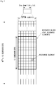
- FIG. 2 is a diagram illustrating a resource grid for one downlink slot in a wireless communication system to which an embodiment of the present invention may be applied.
- one downlink slot includes a plurality of OFDM symbols in a time domain. It is described herein that one downlink slot includes 7 OFDMA symbols and one resource block includes 12 subcarriers for exemplary purposes only, and the present invention is not limited thereto.
- Each element on the resource grid is referred to as a resource element, and one resource block (RB) includes 12 ⁇ 7 resource elements.
- the number of RBs N ⁇ DL included in a downlink slot depends on a downlink transmission bandwidth.
- the structure of an uplink slot may be the same as that of a downlink slot.
- FIG. 3 shows the structure of a downlink subframe in a wireless communication system to which an embodiment of the present invention may be applied.
- a maximum of three OFDM symbols located in a front portion of a first slot of a subframe correspond to a control region in which control channels are allocated, and the remaining OFDM symbols correspond to a data region in which a physical downlink shared channel (PDSCH) is allocated.
- Downlink control channels used in 3GPP LTE include, for example, a physical control format indicator channel (PCFICH), a physical downlink control channel (PDCCH), and a physical hybrid-ARQ indicator channel (PHICH).
- a PCFICH is transmitted in the first OFDM symbol of a subframe and carries information about the number of OFDM symbols (i.e., the size of a control region) which is used to transmit control channels within the subframe.
- a PHICH is a response channel for uplink and carries an acknowledgement (ACK)/not-acknowledgement (NACK) signal for a Hybrid Automatic Repeat Request (HARQ).
- Control information transmitted in a PDCCH is called Downlink Control Information (DCI).
- DCI includes uplink resource allocation information, downlink resource allocation information, or an uplink transmission (Tx) power control command for a specific UE group.
- a PDCCH may carry information about the resource allocation and transport format of a downlink shared channel (DL-SCH) (this is also called an "downlink grant”), resource allocation information about an uplink shared channel (UL-SCH) (this is also called a “uplink grant”), paging information on a PCH, system information on a DL-SCH, the resource allocation of a higher layer control message, such as a random access response transmitted on a PDSCH, a set of transmission power control commands for individual UE within specific UE group, and the activation of a Voice over Internet Protocol (VoIP), etc.
- a plurality of PDCCHs may be transmitted within the control region, and UE may monitor a plurality of PDCCHs.
- a PDCCH is transmitted on a single Control Channel Element (CCE) or an aggregation of some contiguous CCEs.
- CCE is a logical allocation unit that is used to provide a PDCCH with a coding rate according to the state of a radio channel.
- a CCE corresponds to a plurality of resource element groups.
- the format of a PDCCH and the number of available bits of a PDCCH are determined by an association relationship between the number of CCEs and a coding rate provided by CCEs.
- An eNB determines the format of a PDCCH based on DCI to be transmitted to UE and attaches a Cyclic Redundancy Check (CRC) to control information.
- CRC Cyclic Redundancy Check
- a unique identifier (a Radio Network Temporary Identifier (RNTI)) is masked to the CRC depending on the owner or use of a PDCCH. If the PDCCH is a PDCCH for specific UE, an identifier unique to the UE, for example, a Cell-RNTI (C-RNTI) may be masked to the CRC.
- RNTI Radio Network Temporary Identifier
- a paging indication identifier for example, a Paging-RNTI (P-RNTI) may be masked to the CRC.
- P-RNTI Paging-RNTI
- SIB System Information Block
- SI-RNTI System Information-RNTI
- RA-RNTI Random Access-RNTI
- the enhanced PDCCH (EPDCCH) carries UE-specific signaling.
- the EPDCCH is located in a physical resource block (PRB) that is configured to be UE specific.
- PRB physical resource block
- the PDCCH may be transmitted in up to three OFDM symbols in the first slot in the subframe, but the EPDCCH can be transmitted in a resource region other than the PDCCH.
- the time (i.e., symbol) at which the EPDCCH starts in the subframe may be configured in the UE via higher layer signaling (e.g., RRC signaling, etc.).
- the EPDCCH may carry a transport format, resource allocation, and HARQ information associated with DL-SCH, a transport format, resource allocation, and HARQ information associated with UL-SCH, resource allocation information associated with Sidelink Shared Channel (SL-SCH) and Physical Sidelink Control Channel (PSCCH), etc.
- Multiple EPDCCHs may be supported and the UE may monitor the set of EPCCHs.
- the EPDCCH may be transmitted using one or more successive enhanced CCEs (ECCEs) and the number of ECCEs per EPDCCH may be determined for each EPDCCH format.
- ECCEs enhanced CCEs
- Each ECCE may be constituted by a plurality of enhanced resource element groups (EREGs).
- the EREG is used for defining mapping of the ECCE to the RE.
- the UE may monitor a plurality of EPDCCHs.
- one or two EPDCCH sets may be configured in one PRB pair in which the UE monitors EPDCCH transmission.
- Different coding rates may be implemented for the EPCCH by merging different numbers of ECCEs.
- the EPCCH may use localized transmission or distributed transmission, and as a result, the mapping of the ECCE to the RE in the PRB may vary.
- FIG. 4 shows the structure of an uplink subframe in a wireless communication system to which an embodiment of the present invention may be applied.
- the uplink subframe may be divided into a control region and a data region in a frequency domain.
- a physical uplink control channel (PUCCH) carrying uplink control information is allocated to the control region.
- a physical uplink shared channel (PUSCH) carrying user data is allocated to the data region.
- PUCCH physical uplink control channel
- PUSCH physical uplink shared channel
- a Resource Block (RB) pair is allocated to a PUCCH for one UE within a subframe. RBs belonging to an RB pair occupy different subcarriers in each of 2 slots. This is called that an RB pair allocated to a PUCCH is frequency-hopped in a slot boundary.
- a communication environment considered in embodiments of the present invention includes multi-carrier supporting environments. That is, a multi-carrier system or a carrier aggregation system used in the present invention means a system that aggregates and uses one or more component carriers (CCs) having a smaller bandwidth smaller than a target band at the time of configuring a target wideband in order to support a wideband.
- CCs component carriers
- multi-carriers mean aggregation of (alternatively, carrier aggregation) of carriers and in this case, the aggregation of the carriers means both aggregation between continuous carriers and aggregation between non-contiguous carriers. Further, the number of component carriers aggregated between the downlink and the uplink may be differently set.
- ⁇ DL CC' A case in which the number of downlink component carriers (hereinafter, referred to as 'DL CC') and the number of uplink component carriers (hereinafter, referred to as 'UL CC') are the same as each other is referred to as symmetric aggregation and a case in which the number of downlink component carriers and the number of uplink component carriers are different from each other is referred to as asymmetric aggregation.
- the carrier aggregation may be used mixedly with a term such as the carrier aggregation, the bandwidth aggregation, spectrum aggregation, or the like.
- the carrier aggregation configured by combining two or more component carriers aims at supporting up to a bandwidth of 100 MHz in the LTE-A system.
- the bandwidth of the carriers to be combined may be limited to a bandwidth used in the existing system in order to maintain backward compatibility with the existing IMT system.
- the existing 3GPP LTE system supports bandwidths of 1.4, 3, 5, 10, 15, and 20 MHz and a 3GPP LTE-advanced system (that is, LTE-A) may be configured to support a bandwidth larger than 20 MHz by using on the bandwidth for compatibility with the existing system.
- the carrier aggregation system used in the preset invention may be configured to support the carrier aggregation by defining a new bandwidth regardless of the bandwidth used in the existing system.
- the LTE-A system uses a concept of the cell in order to manage a radio resource.
- the carrier aggregation environment may be called a multi-cell environment.
- the cell is defined as a combination of a pair of a downlink resource (DL CC) and an uplink resource (UL CC), but the uplink resource is not required. Therefore, the cell may be constituted by only the downlink resource or both the downlink resource and the uplink resource.
- the cell may have one DL CC and one UL CC, but when the specific terminal has two or more configured serving cells, the cell has DL CCs as many as the cells and the number of UL CCs may be equal to or smaller than the number of DL CCs.
- the DL CC and the UL CC may be configured. That is, when the specific terminal has multiple configured serving cells, a carrier aggregation environment having UL CCs more than DL CCs may also be supported. That is, the carrier aggregation may be appreciated as aggregation of two or more cells having different carrier frequencies (center frequencies).
- the described 'cell' needs to be distinguished from a cell as an area covered by the base station which is generally used.
- the cell used in the LTE-A system includes a primary cell (PCell) and a secondary cell (SCell).
- the P cell and the S cell may be used as the serving cell.
- a terminal which is in an RRC_CONNECTED state but does not have the configured carrier aggregation or does not support the carrier aggregation
- only one serving constituted by only the P cell is present.
- one or more serving cells may be present and the P cell and one or more S cells are included in all serving cells.
- the serving cell may be configured through an RRC parameter.
- PhysCellId as a physical layer identifier of the cell has integer values of 0 to 503.
- SCellIndex as a short identifier used to identify the S cell has integer values of 1 to 7.
- ServCellIndex as a short identifier used to identify the serving cell (P cell or S cell) has the integer values of 0 to 7. The value of 0 is applied to the P cell and SCellIndex is previously granted for application to the S cell. That is, a cell having a smallest cell ID (alternatively, cell index) in ServCellIndex becomes the P cell.
- the P cell means a cell that operates on a primary frequency (alternatively, primary CC).
- the terminal may be used to perform an initial connection establishment process or a connection re-establishment process and may be designated as a cell indicated during a handover process.
- the P cell means a cell which becomes the center of control associated communication among serving cells configured in the carrier aggregation environment. That is, the terminal may be allocated with and transmit the PUCCH only in the P cell thereof and use only the P cell to acquire the system information or change a monitoring procedure.
- An evolved universal terrestrial radio access may change only the P cell for the handover procedure to the terminal supporting the carrier aggregation environment by using an RRC connection reconfiguration message (RRCConnectionReconfiguration) message of an upper layer including mobile control information (mobilityControlInfo).
- RRCConnectionReconfiguration RRC connection reconfiguration message
- mobilityControlInfo mobile control information
- the S cell means a cell that operates on a secondary frequency (alternatively, secondary CC). Only one P cell may be allocated to a specific terminal and one or more S cells may be allocated to the specific terminal.
- the S cell may be configured after RRC connection establishment is achieved and used for providing an additional radio resource.
- the PUCCH is not present in residual cells other than the P cell, that is, the S cells among the serving cells configured in the carrier aggregation environment.
- the E-UTRAN may provide all system information associated with a related cell which is in an RRC_CONNECTED state through a dedicated signal at the time of adding the S cells to the terminal that supports the carrier aggregation environment.
- a change of the system information may be controlled by releasing and adding the related S cell and in this case, the RRC connection reconfiguration (RRCConnectionReconfiguration) message of the upper layer may be used.
- the E-UTRAN may perform having different parameters for each terminal rather than broadcasting in the related S cell.
- the E-UTRAN adds the S cells to the P cell initially configured during the connection establishment process to configure a network including one or more S cells.
- the P cell and the S cell may operate as the respective component carriers.
- the primary component carrier (PCC) may be used as the same meaning as the P cell and the secondary component carrier (SCC) may be used as the same meaning as the S cell.
- FIG. 5 illustrates examples of a component carrier and carrier aggregation in the wireless communication system to which the present invention can be applied.
- FIG. 5a illustrates a single carrier structure used in an LTE system.
- the component carrier includes the DL CC and the UL CC.
- One component carrier may have a frequency range of 20 MHz.
- FIG. 5b illustrates a carrier aggregation structure used in the LTE system.
- FIG. 9b a case is illustrated, in which three component carriers having a frequency magnitude of 20 MHz are combined.
- Each of three DL CCs and three UL CCs is provided, but the number of DL CCs and the number of UL CCs are not limited.
- the terminal may simultaneously monitor three CCs, and receive downlink signal/data and transmit uplink signal/data.
- the network may allocate M (M ⁇ N) DL CCs to the terminal.
- the terminal may monitor only M limited DL CCs and receive the DL signal.
- the network gives L (L ⁇ M ⁇ N) DL CCs to allocate a primary DL CC to the terminal and in this case, UE needs to particularly monitor L DL CCs.
- Such a scheme may be similarly applied even to uplink transmission.
- a linkage between a carrier frequency (alternatively, DL CC) of the downlink resource and a carrier frequency (alternatively, UL CC) of the uplink resource may be indicated by an upper-layer message such as the RRC message or the system information.
- a combination of the DL resource and the UL resource may be configured by a linkage defined by system information block type 2 (SIB2).
- the linkage may mean a mapping relationship between the DL CC in which the PDCCH transporting a UL grant and a UL CC using the UL grant and mean a mapping relationship between the DL CC (alternatively, UL CC) in which data for the HARQ is transmitted and the UL CC (alternatively, DL CC) in which the HARQ ACK/NACK signal is transmitted.
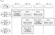
- FIG. 6 is a diagram illustrating division of cells in a system that supports the carrier aggregation.
- a configured cell as a cell that may perform carrier aggregation based on a measurement report among cells of a base station as illustrated in FIG. 5 may be configured for each UE.
- the configured cell may reserve resources for ack/nack transmission for PDSCH transmission in advance.
- An activated cell as a cell configured to transmit a PDSCH / PUSCH among the configured cells performs Channel State Information (CSI) reporting and (Sounding Reference Signal (SRS) transmission for PDSCH/PUSCH transmission.
- CSI Channel State Information
- SRS Sounding Reference Signal
- a de-activated cell as a cell that prevents PDSCH/PUSCH transmission due to a command of the base station or a timer operation may also stop the CSI reporting and the SRS transmission.
- FIG. 7 is a diagram illustrating a random access symbol group.
- a physical layer random access preamble is based on a single subcarrier frequency hopping symbol group.
- the symbol group is constituted by a cyclic prefix (CP) having a length of T cp and a sequence of five identical symbols having a total length of T SEQ .
- CP cyclic prefix
- Table 3 shows an example of each parameter value for the preamble format.
- a preamble constituted by four symbol groups transmitted with no gap needs to be transmitted N rep NPRACH times.
- transmission of the random access preamble may be limited to a specific time and a frequency resource and an NPRACH configuration provided by an upper layer may include the following matters.
- a gap of 40 ⁇ 30720 T s time unit may be inserted after transmission of 4 ⁇ 64( T CP + T SEQ ) time unit and an NPRACH configuration which is N scoffset NPRACH + N sc NPRACH > N sc UL may not be valid.
- Start subcarriers of the NPRACH allocated to the contention based NPRACH NPRACH random access may be classified into two sets of subcarriers of 0,1 , ... , N sc _ cont NPRACH N MSG 3 NPRACH ⁇ 1 and N sc _ cont NPRACH N MSG 3 NPRACH , ... , N sc _ cont NPRACH ⁇ 1 and when a second set exists, the second set may indicate the UE supporting the multi-tone message 3 transmission.
- a frequency location of an i-th symbol group may be given by Equation 1 below.
- the time-continuous random access signal s i (t) for symbol group i may be defined by Equation 2 below.
- s i t ⁇ NPRACH e j 2 ⁇ n SC RA i + Kk 0 + 1 / 2 ⁇ f RA t ⁇ T CP
- n SC RA i The location in the frequency domain controlled by the parameter n SC RA i may be derived from the aforementioned method and the variable ⁇ f RA may be given by Table 4 below. [Table 4] Preamble format ⁇ f RA 0,1 3.75 kHz
- the information element (IE) PUSCH-ConfigCommon may be used to specify the common PUSCH configuration and the reference signal configuration for PUSCH and PUCCH and the IE PUSCH-ConfigDedicated may be used to specify the UE specific PUSCH configuration.
- Table 5 below shows an example of the PUSCH-Config configuration and Table 6 shows the definition of the parameter.
- symPUSCH-UpPTS Indicates the number of data symbols that configured for PUSCH transmission in UpPTS. Values sym2, sym3, sym4, sym5 and sym6 can be used for normal cyclic prefix and values sym1, sym2, sym3, sym4 and sym5 can be used for extended cyclic prefix, see TS 36.213 [23, 8.6.2] and TS 36.211 [21, 5.3.4].
- IE PRACH-ConfigSIB and IE PRACH-Config are used to specify the PRACH configuration in system information and mobility control information, respectively and the IEs of the PRACH-Config are shown in Table 7 below.
- Table 8 shows the definition of each parameter in Table 7.
- PRACH-Config field descriptions PRACH-Config field descriptions initial-CE-level Indicates initial PRACH CE level at random access, see TS 36.321 [6]. If not configured, UE selects PRACH CE level based on measured RSRP level, see TS 36.321 [6].
- highSpeedFlag Parameter High-speed-flag, see TS 36.211 [21, 5.7.2].
- TRUE corresponds to Restricted set and FALSE to Unrestricted set.
- maxNumPreambleAttemptCE Maximum number of preamble transmission attempts per CE level. See TS 36.321 [6]. If the field is absent, the UE shall use the default value n3.
- mpdcch-NarrowbandsToMonitor Narrowbands to monitor for MPDCCH for RAR see TS 36.213 [23, 6.2].
- Field values (1.. maxAvailNarrowBands-r13 ) correspond to narrowband indices (0..[ maxAvailNarrowBands-r13-1 ]) as specified in TS 36.211 [21].
- mpdcch-NumRepetition-RA Maximum number of repetitions for MPDCCH common search space (CSS) for RAR, Msg3 and Msg4, see TS 36.211 [21].
- mpdcch-startSF-CSS-RA Starting subframe configuration for MPDCCH common search space (CSS), including RAR, Msg3 retransmission, PDSCH with contention resolution and PDSCH with CCCH MAC SDU, see TS 36.211 [21] and TS 36.213 [23].
- Value v1 corresponds to 1
- value vldot5 corresponds to 1.5, and so on.
- numRepetitionPerPreambleAttempt Number of PRACH repetitions per attempt for each CE level See TS 36.211 [21].
- prach-ConfigIndexHighSpeed Parameter prach-ConfigurationIndexHighSpeed, see TS 36.211 [21, 5.7.1]. If this field is present, the UE shall ignore prach-Configlndex. prach-FreqOffset Parameter: prach-FrequencyOffset, see TS 36.211 [21, 5.7.1]. For TDD the value range is dependent on the value of prach-Configlndex. prach-FreqOffsetHighSpeed Parameter: prach-FrequencyOffsetHighSpeed, see TS 36.211 [21, 5.7.1]. For TDD the value range is dependent on the value of prach-ConfigIndexHighSpeed. If this field is present, the UE shall ignore prach-FreqOffset.
- prach-HoppingOffset Parameter PRACH frequency hopping offset, expressed as a number of resource blocks, see TS 36.211 [21, 5.7.1]
- prach-ParametersListCE Configures PRACH parameters for each CE level. The first entry in the list is the PRACH parameters of CE level 0, the second entry in the list is the PRACH parameters of CE level 1, and so on.
- prach-StartingSubframe PRACH starting subframe periodicity expressed in number of subframes available for preamble transmission (PRACH opportunities), see TS 36.211 [21].
- Value sf2 corresponds PRACH-Config field descriptions to 2 subframes
- sf4 corresponds to 4 subframes and so on.
- EUTRAN configures the PRACH starting subframe periodicity larger than or equal to the number of PRACH repetitions per attempt for each CE level ( numRepetitionPerPreambleAttempt ). If the field is absent, the value is determined implicitly in TS 36.211 [21, 5.7.1].
- rootSequenceIndexHighSpeed The field indicates starting logical root sequence index used to derive the 64 random access preambles based on restricted set type B in high speed scenario, see TS 36.211 [21, 5.7.2]. If this field is present, the UE shall generate random access preambles based on restricted set type B and ignore rootSequenceIndex.
- rsrp-ThresholdsPrachInfoList The criterion for BL UEs and UEs in CE to select PRACH resource set. Up to 3 RSRP threshold values are signalled to determine the CE level for PRACH, see TS 36.213 [23]. The first element corresponds to RSRP threshold 1, the second element corresponds to RSRP threshold 2 and so on, see TS 36.321 [6]. The UE shall ignore this field if only one CE level, i.e. CE level 0, is configured in prach-ParametersListCE. The number of RSRP thresholds present in rsrp-ThresholdsPrachInfoList is equal to the number of CE levels configured in prach-ParametersListCE minus one.
- zeroCorrelationZoneConfig Parameter N CS configuration, see TS 36.211 [21, 5.7.2: table 5.7.2-2] for preamble format 0..3 and TS 36.211 [21, 5.7.2: table 5.7.2-3] for preamble format 4.
- zeroCorrelationZoneConfigHighSpeed The field indicates N CS configuration for the restricted set type B in high speed scenario, PRACH-Config field descriptions see TS 36.211 [21, 5.7.2]. If this field is present, the UE shall generate random access preambles based on restricted set type B and ignore zeroCorrelationZoneConfig.
- Narrowband (NB)-LTE refers to a system for supporting low complexity and low power consumption with a system bandwidth (system BW) corresponding to 1 Physical Resource Block (PRB) of LTE system.
- system BW system bandwidth
- PRB Physical Resource Block
- the NB-LTE system may be primarily used as a communication mode for implementing the internet of things (IoT) by supporting a device (or UE) such as machine-type communication (MTC) in a cellular system. That is, the NB-LTE system may also be referred to as NB-IoT.
- IoT internet of things
- MTC machine-type communication
- the NB-IoT system does not need to allocate an additional band for the NB-IoT system by using the same OFDM parameters such as the subcarrier spacing used in the existing LTE system, as the LTE system.
- 1 PRB of the legacy LTE system band is allocated for the NB-IoT, which is advantageous in using the frequency efficiently.
- the physical channel of the NB-IoT system may be defined as N-Primary Synchronization Signal (N-PSS), N-Secondary Synchronization Signal (N-SSS), N-Physical Channel (N-PBCH), N-PDCCH/N-EPDCCH, N-PDSCH, or the like in the case of downlink.
- N-PSS N-Primary Synchronization Signal
- N-SSS N-Secondary Synchronization Signal
- N-PBCH N-Physical Channel
- N-PDCCH/N-EPDCCH N-PDSCH, or the like in the case of downlink.
- 'N-' may be used for distinguishing from the legacy LTE.
- the UE may transmit NPRACH (N-PRACH) in a single-tone transmission scheme.
- N-PRACH NPRACH
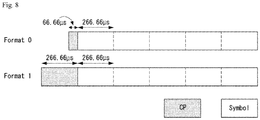
- FIG. 8 is a diagram illustrating an NPRACH (N-PRACH) preamble format.
- the existing FDD NB-IoT uses NPRACH preambles of two formats.
- the existing NPRACH preamble is subjected to single tone transmission and has a subcarrier spacing of 3.75 kHz.
- the NPRACH preamble may be configured by one symbol group by combining five symbols and one CP and the length of the CP is different according to the format type.
- format 0 is constituted by a CP of 66.66 ⁇ s and five consecutive symbols of 266.77 ⁇ s, and as a result, the symbol length becomes 1.4 ms and format 1 is constituted by a CP of 266.66 ⁇ s and five consecutive symbols of 266.77 ⁇ s, and as a result, the symbol length becomes 1.6 ms.
- the length of four consecutive symbol groups constituting a single repetition is 5.6 ms when using format 0 and 6.4 ms when using format 1.
- FIG. 9 is a diagram illustrating an example of hopping and spacing of an NPRACH preamble.
- the NPRACH preamble may have two hopping patterns. That is, a first hopping pattern in which the NPRACH is hopped with an interval of the subcarrier interval and a second hopping pattern in which the NPRACH is hopped with an interval of 6 times the subcarrier interval.
- this specification proposes a method for configuring a preamble which may be newly introduced in addition to the existing NPRACH preamble and operations of the eNB and the UE associated therewith.
- legacy preamble Since there is a limit in transmission range by the existing PRACH preamble (hereinafter, legacy preamble), an enhanced format preamble needs to be defined in addition to the legacy preamble for extending the transmission range of the preamble.
- Such an enhanced format preamble may have a subcarrier spacing of a smaller value than the legacy preamble.
- the subcarrier spacing of the legacy preamble having format 0/1 is 3.75 kHz as described above.
- a preamble having an enhanced format may have a subcarrier spacing of 1.25 kHz smaller than 3.75 kHz.
- a maximum of 48 subcarriers may be used for a single carrier (1 RB, 180 kHz) and 48 RAPIDs of 0 to 47 may be used according to the number of usable subcarriers.
- the subcarrier spacing of the enhanced format PRACH preamble is smaller than 3.75 kHz, the maximum number of subcarriers usable in the single carrier, and as a result, the number of RAPIDs need to also increase.
- this specification proposes a method for efficiently configuring a subcarrier index associated with a subcarrier index (e.g., preamble index and RAPID of RAN2) for introducing the enhanced preamble format.
- a subcarrier index e.g., preamble index and RAPID of RAN2
- the present invention may be extended to various cases in which the subcarrier index needs to be changed with introduction of the enhanced preamble format and is described by considering a TDD in-band mode or guard band mode, but it is apparent that the present invention may be adopted even in a standalone mode.
- FIG. 10 is a diagram illustrating an example of an MAC (random access response (RAR).
- RAR random access response
- FIG. 10(a) illustrates an example of an E/T/RAPID MAC sub-header of NB-IoT
- FIG. 10(b) illustrates an example of an E/T/RR/BI MAC sub-header of NB-IoT
- FIG. 10(c) illustrates an example of the MAC RAR of NB-IoT.
- the subcarrier spacing of the enhanced preamble is smaller than 3.75 kHz, the number of usable RAPIDs which is larger than 48 in the related art may also be used.
- the embodiment described a method for allocating the index of the subcarrier for transmitting the enhanced preamble in the case of sharing the NPRACH resource of a preamble (hereinafter, referred to as new preamble) of an enhanced format (hereinafter, referred to as format 2) with the NPRACH of the legacy preamble.
- new preamble a preamble
- format 2 an enhanced format
- the resource for transmitting the enhanced preamble is not separately allocated, and as a result, the existing resource needs to be used together with the legacy preamble.
- 16 RAPIDs of 48 to 63 may be used for the enhanced preamble except for the RAPIDs of 0 to 47 for the existing preamble among a maximum of 64 RAPIDs usable in the related art.
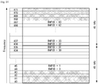
- FIG. 11 is a diagram illustrating an example of a subcarrier index for preamble transmission to which a method proposed by this specification may be applied.
- the resource for transmitting the enhanced preamble may be configured to overlap with the resource for transmitting the legacy preamble on the frequency.
- the start subcarrier index may be configured according to a predetermined specific rule.
- the index of the start subcarrier for transmitting the enhanced preamble may be configured according to the predetermined rule and indexes of the remaining subcarriers for transmitting the enhanced remaining preambles may be configured based on the configured start subcarrier index.
- the predetermined rule may be configured such a manner that the location of the start subcarrier is used by a specific value by considering inter carrier interference.
- a basic unit of an NPRACH resource boundary for the enhanced preamble needs to be equal to that of the NPRACH resource boundary for the legacy preamble, 45 kHz may be maintained as the basic unit.
- the basic unit of the resource boundary becomes 45 kHz (3.75 kHz ⁇ 12). Accordingly, the number of tones may be determined in order to fit the basic unit of the resource boundary to 45 kHz even for the enhanced preamble.
- the subcarrier spacing of the enhanced preamble is 1.25 kHz
- the RAPID for the enhanced preamble shares the resource with the legacy preamble, only 16 RAPIDs may be used and a region of an NPRACH resource for the enhanced preamble may not be more than 45 kHz.
- a predetermined RAPID rule may be shown in Equation 3 below. 48 + floor SC EP / 3
- SC EP means the subcarrier index used for transmitting the enhanced preamble.
- the RAPID of the enhanced preamble may be configured by adding a cell specific configured offset.
- the RAPID may be configured by Equation 4 below. 48 + floor SC EP + SC EP , offset / 3
- the cell specific offset value may have a value of 0 or 2 so that the enhanced preamble may operate.
- the cell specific offset value when the cell specific offset value has the value of '1', the cell specific offset value invades a place occupied by the legacy preamble, it may be configured that the cell specific offset value adopts only 0 or 2.
- Table 9 shows an example of an RAPID of the enhanced preamble depending on the cell specific offset value.
- SCEP+SCEP, offset RAPID 48 + floor ⁇ (SCEP+SCEP, offset)/3 ⁇ 0 or 2 48 3 or 5 49 6 or 8 50 9 or 11 51 12 or 14 52 15 or 17 53 18 or 20 54 21 or 23 55 24 or 26 56 27 or 29 57 30 or 32 58 33 or 35 59
- a value of SC EP +SC EP, offset may be a result value of applying modular 36 to an index of an actually selected subcarrier.
- FIG. 12 is a diagram illustrating still yet another example of the subcarrier index for preamble transmission to which the method proposed by this specification may be applied.
- the index (or RAPID) of the subcarrier for transmitting the enhanced preamble may be differently configured according to the configuration of the resource region.
- the RAPID of the legacy preamble for the legacy UE is set from 0 to 47, but the RAPID of the enhanced preamble may be determined according to the number of the resource region configured through the legacy System Information Block (SIB).
- SIB legacy System Information Block
- the RAPID for the enhanced preamble may be configured like ⁇ 12 to 63, 24 to 63, 36 to 63, 48 to 63 ⁇ .
- one of 16 RAPIDs may be selected and applied for one new preamble and the region of the NPRACH resource for the enhanced preamble can be set to a value greater than 45 kHz.
- the RAPID may be configured every one subcarrier index based on 1.25 kHz and even though one RAPID is configured in an actually configured resource region, when the set total number of RAPIDs is smaller than a maximum number, the remaining region may be configured as reserved.
- the location of the subcarrier in which the enhanced preamble is transmitted may be determined according to a value configured by SIB and the RAPID may be independently configured.
- the RAPID of the enhanced preamble may be configured so that 24 to 59 are used as illustrated in FIG. 12(a) .
- the RAPID of the enhanced preamble may be configured so that 24 to 59 are used as illustrated in FIG. 12(b) .
- FIGS. 12(a) and 12(b) may be applied even to a case where the NPRACH resource of the enhanced preamble is not shared with the NPRACH resource.
- the resource for the legacy NPRACH is may be configured to one of ⁇ n12, n24, n36, n48 ⁇ and the resource for transmitting the enhanced preamble may be configured to the subcarrier having the largest index based on the subcarrier index among the resources configured for the legacy NPRACH.
- the RAPID for the enhanced preamble may adopt a part of the RAPID of the legacy preamble.
- the subcarrier for the enhanced preamble may be allocated to a subcarrier having a largest index value among the subcarriers capable of transmitting the legacy preamble.
- the UE that transmits the enhanced preamble may recognize that the UEs transmitting the legacy preamble do not transmit the legacy preamble in the corresponding region.
- the resource for the enhanced preamble may be configured in a specific region (e.g., contention free region) of the NPRACH resource for the legacy preamble.
- the RAPID for the enhanced preamble is not newly configured and used and the legacy RAPID may be used.
- the UE may be configured to select the subcarrier index based on a subcarrier spacing of 3.75 kHz and use the RAPID corresponding to the selected subcarrier index.
- the enhanced preamble uses a subcarrier spacing (e.g., 1.25 kHz) smaller than 3.75 kHz
- a plurality of subcarriers for transmitting the enhanced preamble may be present in the subcarrier selected by the UE and the UE may transmit the enhanced preamble by selecting one of the plurality of subcarriers.
- the subcarrier spacing for the enhanced preamble is 1.25 kHz
- a maximum of three candidate subcarriers may be present in the subcarrier selected by the UE and the UE may transmit the enhanced preamble by selecting one of three candidate subcarriers.
- all UEs may be configured to select one of three candidate subcarriers based on the same value in the same cell and different cells may have different values.
- the UE may select one subcarrier based on a cell ID among three candidate subcarriers for transmitting the enhanced preamble.
- SC 1.75 which is an index of the subcarrier having the subcarrier spacing of 1.75 kHz for actually transmitting the enhanced preamble may be determined as shown in Equation 5 below.
- SC 1.25 SC 3.75 ⁇ 3 + CID modular 3
- SC 1.25 may become 98.
- the UE may transmit the enhanced preamble to subcarrier #98.
- Equation 3 3 is inserted because the subcarrier spacing is 3 times between 3.75 kHz and 1.25 kHz and a value of Equation '3' may be changed according to a difference value of the subcarrier spacing.
- a specific subcarrier index (e.g., based on 1.25 kHz) used specific to the cell is determined, there is an effect that an influence of inter-carrier-interference between the UEs transmitting the enhanced preamble is reduced in an intra cell.
- the resource for the enhanced preamble may be configured in the specific region (e.g., contention free region) of the NPRACH resource for the legacy preamble.
- the RAPID may be configured by using the 6-bit field and the reserved field of the RAR sub-header.
- K (K is a positive integer smaller than 47) subcarriers are configured for the NPRACH resource or K subcarriers are configured to a region for the legacy preamble through an additional parameter (for example, when RAPIDs of 0 to K-1 are used for the legacy preamble)
- K to 62 may be expressed as the 6-bit field of the sub-header of the RAR, and as a result, there is no case of confusion with the legacy preamble.
- RAPIDs of 63 to RAPID MAX -1 may be configured by using the reserved field of the RAR.
- the RAPID field value of the RAR sub-header may be fixed and set to a specific value.
- the UE may verify the RAPID through the reserved field of the RAR other than the RAPID field of the sub-header.
- RAPID When the reserved field of the RAR has a total of 6 bits, but 5 bits which are consecutively present are configured to be used in order to represent the RAPID of the enhanced preamble, a maximum of 63 RAPIDs may be additionally expressed (when 6 bits are used, a maximum of 127 RAPIDs may be additionally expressed).
- the RAPID of the enhanced preamble does not overlap even the RAPID used for the legacy preamble, and as a result, there is an influence on the legacy UE.
- the RAPID may be configured by using bits other than bits used for the legacy preamble in the sub-header.
- the legacy UE may recognize that the corresponding RAR is not the RAR for the legacy preamble.
- the RAPID value of the enhanced preamble may be configured to be configured through the reserved field of the RAR and transmitted to the UE.
- the RAPID value for the enhanced preamble may be set to 0 to 63 or K to K + 63.
- RAPIDs When 6 bits are used as the reserved field of the RAR for the enhanced preamble, a maximum of 127 RAPIDs may be additionally represented.
- the RAPID used by the legacy preamble and the RAPID of the enhanced preamble do not overlap with each other, and as a result, there is no influence on the legacy UE.
- the legacy UE may recognize that the corresponding RAR is not the RAR for the legacy preamble by the RAPID field value of the RAR sub-header verified by the legacy UE, and as a result, there is no influence on the legacy UE.
- the enhanced preamble may be configured to use all of 64 RAPIDs of 0 to 63.
- the base boundary (e.g., wraparound reference) of the legacy NPRACH resource may be 45 kHz (e.g., 12 tones). Since the subcarrier spacing of the enhanced preamble has a smaller value (e.g., 1.25 kHz) than the subcarrier spacing of the legacy preamble, the base boundary of the NPRACH resource of the enhanced preamble may also be newly configured.
- a frequency domain constituted by K tones may be configured to be multiplexed with the legacy NPRACH, NPUSCH, etc.
- K 36 or 48, but K may have other values.
- a maximum hopping gap of the format of the enhanced preamble format is 22.5 kHz
- a region required for wraparound is 45 kHz, twice the maximum hopping gap.
- the value of K may be 36.
- the K value may be 48 in the same scheme.
- the K value may be 32.
- all 64 RAPIDs may be mapped to the subcarriers one to one.
- one value of ⁇ n36, n72, n108, n144 ⁇ may be configured and when the value of K is '48', one value of ⁇ n48, n96, n144 ⁇ may be configured as the NPRACH resource.
- K When K is '48' and the number of subcarriers allocated to the NPRACH for the enhanced preamble format is continuously fixed to 48, it may be configured to use RAPIDs of the same number as the legacy FDD.
- Different methods may be used according to the number of subcarriers set through system information (e.g., SIB2-NB, SIB22-NB, etc.).
- the UE may be configured to use all RAPIDs of 0 to 63 mapped to respective subcarrier indexes one to one.
- N SC NPRACH N SC NPRACH ⁇ 64 which is the set number of subcarriers is n * K (where n is a positive integer equal to or larger than 1) and n and k which cause a value of n * K to be equal to or smaller than 64 may be configured to use RAPIDs of 0 to (n * K) - 1 mapped to the respective subcarrier indexes one to one.
- RAPIDS of n* K to 63 may be left as the reserved.
- the UE may be configured to use RAPIDs of 0 to 63 mapped to predetermined specific subcarrier indexes.
- N SC NPRACH N SC NPRACH > 64 only the remaining 64 subcarrier indexes may be configured to be used other than N SC NPRACH -64 subcarriers among a total of N SC NPRACH subcarriers.
- the selected subcarriers may have the following rule and may be configured as illustrated in FIG. 13 or 14 .
- FIG. 13 is a diagram illustrating yet another example of the subcarrier index for preamble transmission to which the method proposed by this specification may be applied.
- N SC NPRACH N SC NPRACH > 64 which is the set number of subcarriers is m *K (where m is a positive integer equal to or larger than 1) as illustrated in FIG. 13 , the number of subcarriers which needs to be configured not to be used becomes (m ⁇ K - 64) and (m ⁇ K - 64) / 2m from a subcarrier having a largest subcarrier index among each K subcarriers and (m ⁇ K - 64) / 2m from a subcarrier having a smallest subcarrier index may be configured not to be used.
- the remaining 64 subcarriers may be configured to use the RAPID value from 0 to 63 in ascending order from a subcarrier having a small subcarrier index value.
- the UE may be configured to use a total of 72 subcarriers for the enhanced preamble.
- the enhanced NPRACH resource is multiplexed with the legacy NPRACH, NPUSCH, etc., through such a method, carriers which are not used may serve as a guard.
- FIG. 14 is a diagram illustrating still yet another example of the subcarrier index for preamble transmission to which the method proposed by this specification may be applied.
- FIG. 14 Although the method of FIG. 14 is similar to the method described in FIG. 13 , a location of a subcarrier which is not used may be changed.
- N SC NPRACH N SC NPRACH > 64 which is the number of subcarriers set by the eNB is m * K (where m is a positive integer equal to or larger than 1)
- the number of subcarriers which need to be configured not to be used becomes (m ⁇ K - 64) and (m ⁇ K - 64) / 2 from the subcarrier having the largest subcarrier index among each K subcarriers and (m * K - 64) / 2 from the subcarrier having the smallest subcarrier index may be configured not to be used.
- a total of (m * K - 64) subcarriers may be configured not to be used.
- the remaining 64 subcarriers may be configured to use the RAPID value from 0 to 63 in ascending order from a subcarrier having a small subcarrier index value.
- the UE may be configured to use a total of 72 subcarriers for the enhanced preamble.
- Only a subcarrier at a specific location may be preconfigured to be used for transmitting the enhanced preamble regardless of the number of subcarriers set through the system information (e.g., SIB2-NB, SIB22-NB, etc.).
- system information e.g., SIB2-NB, SIB22-NB, etc.
- L RAPIDs are configured to be used per basic region of the NPRACH resource of the enhanced preamble constituted by K subcarriers to use a total of RAPIDs.
- the L value should be configured to have the same value as
- L becomes ⁇ 16' and the total number of usable RAPIDs becomes 64. That is, since only 16 specific subcarriers are used among 36 subcarriers, only 16 specific subcarriers specified to the cell may be configured to be used.
- 16 specific subcarriers may be determined through the following method.
- 16 specific subcarriers distinguish even number Cell ID and odd number Cell ID from each other based on the Cell ID and cells which belong to a first group may be configured as 16 subcarriers other than subcarriers having the smallest index value and the largest index value among even-numbered subcarriers among 36 subcarriers.
- 16 subcarriers other than the subcarriers having the smallest index value and the largest index value may be configured to be used for transmitting the enhanced preamble.
- 16 subcarriers other than the subcarriers having the smallest index value and the largest index value among the even numbered subcarriers may become subcarriers having index values of ⁇ 2, 4, 6, 8, 10, 12, 14, 16, 18, 20, 22, 24, 26, 28, 30, 32 ⁇ .
- 16 subcarriers other than the subcarriers having the smallest index value and the largest index value among odd numbered subcarriers may become subcarriers having index values of ⁇ 3, 5, 7, 9, 11, 13, 15, 17, 19, 21, 23, 25, 27, 29, 31, 33 ⁇ .
- unused subcarriers may serve as the guard when an enhanced NPRACH resource is multiplexed with legacy NPRACH, NPUSCH, and the like.
- Table 10 shows examples of a subcarrier index and RAPID for Embodiment 5-1. Cells of two groups described above may be configured so that the RAPID is determined based on one table.
- SC EP modular 36 RAPID SC EP (0 ⁇ 5) SC EP (36 ⁇ 71) SC EP (72 ⁇ 107) SC EP (108 ⁇ 143) 2 or 3 0 16 32 48 4 or 5 1 17 33 49 6 or 7 2 18 34 50 8 or 9 3 19 35 51 10 or 11 4 20 36 52 12 or 13 5 21 37 53 14 or 15 6 22 38 54 16 or 17 7 23 39 55 18 or 19 8 24 40 56 20 or 21 9 25 41 57 22 or 23 10 26 42 58 24 or 25 11 27 43 59 26 or 27 12 28 44 60 28 or 29 13 29 45 61 30 or 31 14 30 46 62 32 or 33 15 31 47 63
- Embodiment 5-2 has a similar method to Embodiment 5-1, but the even number Cell ID and the odd number Cell ID may be distinguished from each other based on the Cell ID and cells of two groups may determine RAPID based on different tables.
- mapping orders of subcarrier indexes and RAPIDs of cells using subcarriers having odd indexes and cells of using subcarriers having even indexes may be configured to be different from each other.
- a cell having the even number Cell ID may determine the RAPID based on Table 11 below and a cell having the odd number Cell ID may determine the RAPID based on Table 12 below.
- SC EP modular 36 RAPID SC EP (0 ⁇ 5) SC EP (36 ⁇ 71) SC EP (72 ⁇ 107) SC EP (108 ⁇ 143) 32 0 16 32 48 30 1 17 33 49 28 2 18 34 50 26 3 19 35 51 24 4 20 36 52 22 5 21 37 53 20 6 22 38 54 18 7 23 39 55 16 8 24 40 56 14 9 25 41 57 12 10 26 42 58 10 11 27 43 59 8 12 28 44 60 6 13 29 45 61 4 14 30 46 62 2 15 31 47 63
- SC EP modular 36 RAPID SC EP (0 ⁇ 5) SC EP (36 ⁇ 71) SC EP (72 ⁇ 107) SC EP (108 ⁇ 143) 3 0 16 32 48 5 1 17 33 49 7 2 18 34 50 9 3 19 35 51 11 4 20 36 52 13 5 21 37 53 15 6 22 38 54 17 7 23 39 55 19 8 24 40 56 21
- Tables 11 and 12 are reversed in terms of the mapping order of the subcarrier index and the RAPID.
- unused subcarriers may serve as the guard when the enhanced NPRACH resource is multiplexed with legacy NPRACH, NPUSCH, and the like.
- a probability of an RAPID receiving error by inter cell interference may also be reduced.
- a frequency size of performing hopping between symbol groups constituting the enhanced preamble may be configured to have one of four values as shown in Table 13 below according to a value of a start subcarrier of each preamble.
- L may be determined to be '21' and the total number of RAPIDs may be determined to be used according to the method described in Embodiment 5.
- 21 specific subcarriers specific to the cell may be configured to be used and this may reduce the inter cell interference.
- RAPIDs of 0 to 52 may be configured to be used and 63 may be left as reserved.
- 21 specific subcarriers may be configured through Embodiments 5-3 and 5-4 below similarly to Embodiments 5-1 and 5-2.
- 21 specific subcarriers distinguish even number Cell ID and odd number Cell ID from each other based on the Cell ID and the cells which belong to the first group may be configured as even numbered subcarriers other than subcarriers (e.g., 0, 1, 2) having the smallest index value and subcarriers (e.g., 45, 46, 47) having the largest index value among 48 subcarriers.
- even numbered subcarriers become ⁇ 4, 6, 8, 10, 12, 14, 16, 18, 20, 22, 24, 26, 28, 30, 32, 34, 36, 38, 40, 42, 44 ⁇ and odd numbered subcarriers become ⁇ 3, 5, 7, 9, 11, 13, 15, 17, 19, 21, 23, 25, 27, 29, 31, 33, 35, 37, 39, 41, 43 ⁇ other than the subcarriers (e.g., 0, 1 2) having the smallest index value and the subcarriers (e.g., 45, 46, 47) having the largest index value among 48 subcarriers.
- the subcarriers e.g., 45, 46, 47
- unused subcarriers may serve as the guard when an enhanced NPRACH resource is multiplexed with legacy NPRACH, NPUSCH, and the like.
- Table 14 below shows examples of a subcarrier index and RAPID for Embodiment 5-3.
- the cells of two groups described above may be configured so that the RAPID is determined based on one table.
- SC EP modular 48 RAPID SC EP (0 ⁇ 47) SC EP (48 ⁇ 95) SC EP (96 ⁇ 143) 3 or 4 0 21 42 5 or 6 1 22 43 7 or 8 2 23 44 9 or 10 3 24 45 11 or 12 4 25 46 13 or 14 5 26 47 15 or 16 6 27 48 17 or 18 7 28 49 19 or 20 8 29 50 21 or 22 9 30 51 23 or 24 10 31 52 25 or 26 11 32 53 27 or 28 12 33 54 29 or 30 13 34 55 31 or 32 14 35 56 33 or 34 15 36 57 35 or 36 16 37 58 37 or 38 17 38 59 39 or 40 18 39 60 41 or 42 19 40 61 43 or 44 20 41 62
- Embodiment 5-4 has a similar method to Embodiment 5-3, but the even number Cell ID and the odd number Cell ID may be distinguished from each other based on the Cell ID and cells of two groups may determine RAPID based on different tables.
- mapping orders of subcarrier indexes and RAPIDs of cells using subcarriers having odd indexes and cells of using subcarriers having even indexes may be configured to be different from each other.
- a cell having the even number Cell ID may determine the RAPID based on Table 15 below and a cell having the odd number Cell ID may determine the RAPID based on Table 16 below.
- SC EP modular 48 RAPID SC EP (0 ⁇ 47) SC EP (48 ⁇ 95) SC EP (96 ⁇ 143) 44 0 21 42 42 1 22 43 40 2 23 44 38 3 24 45 36 4 25 46 34 5 26 47 32 6 27 48 30 7 28 49 28 8 29 50 26 9 30 51 24 10 31 52 22 11 32 53 20 12 33 54 18 13 34 55 16 14 35 56 14 15 36 57 12 16 37 58 10 17 38 59 8 18 39 60 6 19 40 61 4 20 41 62
- SC EP modular 48 RAPID SC EP (0 ⁇ 47) SC EP (48 ⁇ 95) SC EP (96 ⁇ 143) 3 0 21 42 5 1 22 43 7 2 23 44 9 3 24 45 11 4 25 46 13 5 26 47 15 6 27 48 17 7 28 49 19 8 29 50 21 9 30 51 23 10 31 52 25 11 32 53 27 12 33 54 29 13 34
- the configuration may be made through the following method.
- the RAPID may be configured by using the 6-bit field and the reserved field of the RAR sub-header.
- the eNB may configure the RAPIDs of 0 to 63 to be expressed by only the 6-bit field of the RAR subheader and the RAPID to be represented from 64 to RAPID MAX which is the maximum value of the RAPID by additionally using the reserved field of the RAR.
- a total of 6 bits are present in the reserved field of the RAR, but the number of subcarriers for the enhanced preamble is 144 (when the subcarrier spacing is 1.25 kHz) on a frequency axis, so that a maximum of 144 RAPIDS may be configured to be represented by additionally using 2 bits of the reserved field of the RAR.
- It may be configured to represent the RAPID of the enhanced preamble through a field having a total size of 8 bits by additionally combining 2 bits of the RAR reserved field with 6 bits of the RAR sub-header.
- the size of the field representing the RAPID in the RAR sub-header may be set to 8 bits.
- the UE may be configured to recognize the RAR reserved field as MSB.
- the value of the reserved field is recognized as a foremost value to represent the RAPID.
- the 6-bit field of the RAR sub-header may be configured to represent the value of floor(RAPID/3) and 2 bits of the RAR reserved field may be configured to represent the value of RAPID modular 3.
- the RAPID value is 127
- the preamble may be transmitted by using all subcarriers available on the frequency axis based on the enhanced preamble using the subcarrier spacing of 1.25 kHz.
- the eNB may additionally transmit to the UE a parameter indicating an RAPID offset through an SIB that configures the resource the enhanced preamble.
- the enhanced UE may know that the resource to currently transmit the preamble and the legacy resource should use the same RA-RNTI, the enhanced UE may be configured to receive a first RAPID value for the resource for the enhanced preamble from the eNB by recognizing the RAPID offset value additionally transmitted through the SIB.
- the eNB should transmit the RAPID offset value to the UE (e.g., when the value is 24) and the UE for transmitting the enhanced preamble may be configured to recognize the RAPIDs corresponding to 72 subcarriers as selected subcarrier index + RAPID offset (e.g., 24 to 95).
- the RAPID offset value when the resource for the legacy preamble is configured for each of one or more CE levels in the corresponding carrier, the RAPID offset may be independently transmitted for each CE level.
- a problem may be solved, which occurs when the UEs sharing the same RA-RNTI value also have the RAPID.
- the UE directly recognizes configuration information for the resource for the legacy preamble selecting the start subframe in which the same RA-RNTI value is shared on the time axis may determine the first RAPID value of the resource for the enhanced preamble.
- the UE that is to transmit the enhanced preamble may recognize that the resource to currently transmit the preamble and the legacy resource should the same RA-RNTI, the UE may calculate the maximum value of the RAPID to be used in the legacy resource by verifying the configuration for the legacy resource.
- the UE that is to transmit the enhanced preamble may determine the range of the RAPID value to be used in the resource for the enhanced preamble based on the calculated value and transmit the RAR according to the range.
- the UE that is to transmit the enhanced preamble verifies the configuration corresponding to the resource for the legacy preamble to calculate RAPID legacy_MAX which is the maximum value of the RAPID used by the corresponding resource.
- the UE that calculates the RAPID legacy_MAX may recognize the RAPID corresponding to 72 subcarriers of the resource for the enhanced preamble as the selected subcarrier index + RAPID legacy_MAX .
- the RAPID for the enhanced preamble may be determined to be 12 to 83.
- Such a method may continuously have independent an RAPID MAX depending on overlapping legacy resources.
- a problem may be solved, which occurs when the UEs sharing the same RA-RNTI value also have the RAPID and an additional signaling is not required.
- the RAPID of the enhanced preamble may be configured to adopt only a value after a specific value.
- the UE that is to transmit the enhanced preamble may recognize that the resource to currently transmit the preamble and the legacy resource should the same RA-RNTI, the UE may continuously use only the RAPID after the RAPID legacy_MAX value which is the fixed value.
- the RAPID legacy_MAX value may be 47 which is the maximum value which may be used by the legacy preamble.
- the UE may recognize the RAPIDs corresponding to 72 subcarriers as the selected subcarrier index + RAPID legacy_MAX in the resource for the enhanced preamble.
- the RAPID for the enhanced preamble may be determined to be 48 to 119.
- a problem may be solved, which occurs when the UEs sharing the same RA-RNTI value also have the RAPID and an additional signaling is not required.
- an enhanced preamble that is a preamble using Format 2, which is an enhanced preamble format, may be used in addition to the existing legacy preamble.
- the eNB may configure the DCI field of the NPDCCH differently according to the preamble format of the preamble allocated (or configured) to the UE and transmit the DCI field to the UE.
- the eNB should announce the preamble format of the preamble to be transmitted by the UE and the subcarriers for transmission of the preamble.
- the eNB may encapsulate an indicator indicating the preamble format of the preamble to be transmitted by the UE and a field indicating the subcarrier and transmit the indicator and the field to the UE.
- the indicator may have a value of '0' when the preamble format is 0 or 1 and a value of '1' when the preamble format is 2.
- Preamble format 0 or 1 may have the subcarrier spacing of 3.75 kHz as described above and Preamble format 2 (FDD NPRACH format 2) may have the subcarrier spacing of 1.25 kHz.
- a preamble having the preamble format of 0 or 1 is referred to as a first preamble (or a legacy preamble) and a preamble having the preamble format of 2 is referred to as a second preamble (or an enhanced preamble).
- the NPRACH resources for the second preamble may overlap or may not overlap with the NPRACH resource for the first preamble.
- NPRACH resource for the first preamble and the NPRACH resource for the second preamble each having the same CE level and not overlapping on the same carrier.
- the eNB needs to instruct the UE whether to transmit the first preamble or the second preamble through the NPDCCH order.
- DCI format N1 for the NPDCCH order may include a field having a size of k bits (for example, 1 bit) indicating the preamble to be transmitted by the UE.
- the eNB may encapsulate the indicator indicating the format of the preamble to be transmitted by the UE in the DCI transmitted through the NPDCCH and transmit the indicator.
- Table 17 below shows an example of DCI format N1.
- the length of DCI format N1 may be configured by a total of 24 bits and in order to avoid increasing the number of times of blind decoding of the UE, the remaining bits of 10 bits may be set to '1'.
- Flag for format N0/format N1 differentiation is a flag indicating the format of the DCI and the Starting number of NPRACH repetitions means start number information related to a start number of repetition of the random access procedure.
- Carrier indication of NPRACH represents information related to the carrier for transmission of the preamble.
- DCI format N1 for the NPDCCH order described above configures 1 bit among the remaining 10 bits as the indicator indicating the preamble to be transmitted by the UE, 9 bits are set to '1' and DCI transmitted to the UE through the NPDCCH may thus maintain a length of 24 bits.
- the indicator indicating the preamble to be transmitted by the UE may be referred to as a preamble format indicator or an FDD NPRACH format indication field.
- the UE may transmit a preamble of a format indicated by a preamble format indicator to the eNB in order to perform the RACH procedure and the eNB may transmit a response message to the UE in response thereto.
- the UE may be configured to disregard the value of the preamble format indicator or configured to recognize in advance that the value of the preamble format indicator is fixedly transmitted as a specific value (0 or 1).
- the UE may determine that the corresponding NPDCCH order is not valid.
- the value of the explicit field indicating the preamble is disregarded and the preamble resource which exists in the specific CE level and the specific carrier is selected to transmit the preamble.
- the preamble format indicator may be included in the DCI when the eNB and/or the UE supports Preamble format 2.
- the preamble format indicator may be included in the DCI and transmitted to the UE only when the eNB informs the UE that the eNB supports Preamble format 2 through a higher layer signaling (e.g., RRC signaling).
- a higher layer signaling e.g., RRC signaling
- Such a method may increase the degree of freedom of the eNB.
- the size of the field indicating the subcarrier may be changed according to the preamble format.
- the type of preamble may be distinguished only by 6 bits of a "subcarrier indication of NPRACH" field which is information related to the subcarrier for transmitting the preamble for the RACH procedure in Table 17.
- the subcarrier indication field of the NPRACH may be referred to as a subcarrier indication field.
- all of the states for example, 0 to 47 among 64
- reserved states for example, 48 to 63 among 64
- the UE may know that the value of the preamble format indicator is disregarded or fixedly transmitted to the specific value (0 or 1) if the preamble format indicator described above is commonly included in the DCIs of all UEs.
- the number of bits of the subcarrier indication field needs to be increased in DCI format N1 for the NPDCCH order.
- the number of bits of the subcarrier indication field may be the same or increase.
- preamble format 0/1 has the subcarrier spacing of 3.75 kHz
- the maximum value of the number of RAPIDs of the preamble is 48. That is, a total of 48 subcarriers may be configured for transmission of the preamble in 1 RB (180 kHz) and the UE may transmit the preamble to the eNB through the subcarrier indicated by the subcarrier indication field in the DCI of the eNB.
- the subcarrier indication requires only the size of 6 bits in order to indicate the subcarrier for transmitting the preamble (which may indicate a maximum of 64 RAPIDs in the case of 6 bits).
- the maximum value of the number of RAPIDs of the preamble is 144. That is, a total of 144 subcarriers need to be configured in order to transmit the preamble in 1 RB (180 kHz).
- the subcarrier indication requires a size of at least 8 bits to indicate the subcarrier for transmitting the preamble.
- the size of the subcarrier indication field may be determined according to Equation 4 below. ⁇ log 2 RAPID MAX ⁇
- the number of bits of the subcarrier indicator field may be configured by 7 bits and if the RAPID MAX is larger than 128 and does not exceed 256, the number of bits of the subcarrier indicator field may be configured by 8 bits.
- R may not exceed a maximum of 10 bits by considering the total length (24 bits) of the DCI and 10-R bits which are the remaining bits are set to '1' as described above, and as a result, the total length of the DCI field becomes 24 bits.
- a 1-bit additional field may be further included to instruct DCI format N1 for the NPDCCH order to perform symbol level scrambling or symbol group level scrambling.
- the eNB may instruct the UE to perform the symbol level scrambling or symbol group level scrambling defined by the method known in advance through the DCI.
- Such a method may enhance reliability of the preamble transmitted by the UE when the eNB determines that the corresponding UE is a UE positioned on a boundary with an adjacent cell.
- the second preamble may be a preamble including the symbol level scrambling or symbol group level scrambling or FDD NPRACH format 2 supporting the subcarrier spacing of 1.25 kHz.
- the fields described above may be redundantly required. For example, if there is each of the NPRACH resource for the first preamble and the NPRACH resource for the second preamble that have the same CE level on the same carrier and do not overlap with each other and the maximum value of the number of RAPIDs allowed in the NPRACH resource for the second preamble is 144, the subcarrier indication becomes 8 bits requiring 2 bits in addition to 6 bits and the preamble format indication for indicating the preamble format is required.
- the format indicator field indicating the preamble format may not be added to DCI format N1 for the NPDCCH order.
- the corresponding UE may select the resource corresponding to the preamble format which is successful in the immediately previous RACH procedure and transmit the preamble.
- the UE when the UE is in a connected mode, the UE has an experience in successfully performing the RACH procedure, and as a result, the UE may select the resource corresponding to the preamble and transmit the preamble based on the RACH procedure which is successfully performed in advance.
- the additional field for indicating the preamble format may not be configured in DCI format N1 for the NPDCCH order.
- the UE may select the preamble resource which exists at the corresponding CE level and in the corresponding carrier and transmit the preamble irrespective of the preamble of the RACH procedure which is successfully performed in advance.
- the preamble format indicator indicating the preamble format may not be additionally included in DCI format N1 for the NPDCCH order and there is an effect that the degree of freedom of the eNB may be increased.
- the UE may determine that the NPDCCH order is not valid.
- the UE may predict not to instruct transmission of a preamble different from the recognized preamble.
- the UE may select a preamble resource which is shown first in time among the preamble resources which exist at the specific CE level and in the specific carrier indicated through the corresponding DCI and transmit the preamble.
- the first preamble resource and the second preamble resource may be independently configured on the same CE level and on the same carrier and the RAPID value used for each resource may not exceed 64.
- the UE may select the resource indicated first in time among the preamble resources existing in the specific carrier level and the specific CE level indicated through the corresponding DCI and transmit the preamble.
- the UE may select the second preamble resource and transmit the preamble.
- different FDD NPRACH formats may be configured via the SIB (e.g., SIB 2 or SIB 22) depending on the CE level.
- the preamble format may be implicitly indicated to the UE using the "Starting number of NPRACH repetitions" field of DCI format N1 for the NPDCCH order.
- the CE level and the NPRACH format match the SIB and the NPRACH format indicates only the CE level to the UE, and as a result, the UE may recognize the preamble format matching with the CE level.
- the FDD NPRACH format configured (or matched) for each CE level may be configured differently according to the UE analyzing actual system information (e.g., SIB and RRC).
- the eNB may configure to match the CE level and the FDD NPRACH format so as to use FDD NPRACH format 1 for all CE levels (e.g., CE levels 0, 1, and 2) for UEs not supporting Preamble format 2 according to the configuration (e.g., UEs according to Release) of the UE.
- CE levels e.g., CE levels 0, 1, and 2
- Preamble format 2 e.g., UEs according to Release
- the eNB may match the CE level and the FDD NPRACH format so that CE levels 0 and 1 use FDD NPRACH format 1 and CE level 2 uses FDD NPRACH format 2 for UEs supporting preamble format 2.
- the UE may perform the RACH procedure using FDD NPRACH format 1 when being indicated CE level 2 through the NPDCCH order.
- the UE may perform the RACH procedure using FDD NPRACH format 2 when being indicated CE level 2 through the NPDCCH order.
- a separate indicator may not be added to DCI format N1 for the NPDCCH order in order to indicate the preamble format.
- the following methods may be applied.
- dedicated SR resources that may be transmitted using a specific start carrier may multiplexed through TDM for one or more UEs.
- the number of repetitions of the preamble is determined in advance through the SIB for the NPRACH resource capable of transmitting the dedicated SR.
- the UE for transmitting the dedicated SR already operates in the connected mode and the eNB may receive the dedicated SR even if the preamble is not transmitted repeatedly by the number of repetitions of the preamble corresponding to the corresponding NPRACH resource.
- the eNB may inform the UE of a specific NPRACH resource (e.g., carrier and CE level) through the RRC signaling for the dedicated SR.
- a specific NPRACH resource e.g., carrier and CE level
- a specific set of scaling factors may be specified in the standard, and a value of a scaling factor to be actually used and a timing index (for example, a transmission index based on the scaling factor) to transmit the actual SR may be transmitted to the UE through the RRC signaling.
- the value of the scaling factor may be configured to be specific to the NPRACH resource or specific to the UE.
- the eNB needs to allocate the resource not to overlap with the SR resource of another UE.
- the value of the actual scaling factor may be set to 1/8 and the timing index for SR transmission may be set to 1.
- the UE may repeatedly transmit SR transmissions 16 times from the instant when a 16 (128/8)-th preamble among the single tone resources corresponding to the specific subcarrier index of the NPRACH resource is transmitted.
- the single tone resources for the SR corresponding to the specific subcarrier index may be multiplexed through the TDM scheme and allocated to a plurality of UEs, thereby sufficiently securing a dedicated SR capacity.
- the eNB may announce SR transmission timing offset information and the number of repetitions for the actual SR simultaneously with announcing the specific NPRACH resource (e.g., carrier and CE level) to the UE through the RRC signaling for the transmission SR.
- the specific NPRACH resource e.g., carrier and CE level
- the eNB may set the number of SR repetitions to 32 for a specific UE and set a transmission timing offset to 16 (single tone preamble length).
- the specific UE may repeatedly transmit SR transmissions 32 times from the instant when a 16-th preamble among the single tone resources corresponding to the specific subcarrier index of the NPRACH resource is transmitted.
- the eNB may completely dynamically multiple the single tone resources for the SR corresponding to the specific subcarrier index through the TDM scheme and allocate the multiplexed single tone resources to the plurality of UEs, the dedicated SR capacity may be sufficiently secured and the independent number of repetitions may be allocated to a plurality of UEs requiring the dedicated SR.
- the UE may transfer specific information through a transmission start position on the time axis in the NPRACH resource.
- the transmission start position on the time axis may be one of positions where a first symbol group of each preamble which is repeatedly transmitted is transmitted or one of positions where each symbol group may be transmitted.
- the specific information may include a buffer state report (BSR).
- BSR buffer state report
- the number of NPRACH repetitions corresponding to the set carrier and the CE level is 128 and the number of repetitions of the SR transmission is 32
- one of at four different information (128 / 32) may be transmitted, and one of at most 96 (128 - 32) different information may be transmitted to the UE.
- additional information may be transmitted to the UE even though the NPRACH preamble is not scrambled by an additional sequence.
- FIG. 15 is a diagram illustrating an example of a method for transmitting a random access preamble by a UE to which the method proposed by this specification may be applied.
- the UE may select the preamble format based on the DCI and transmit the preamble to the eNB.
- the UE supports preamble format 2.
- the UE may recognize whether the eNB supports preamble format 2 through the higher layer signaling transmitted from the eNB.
- the UE may recognize whether the eNB supports preamble format 2 by allocating the resource for transmitting NPRACH format 2 at the CE level transmitted through the higher layer signaling (e.g., SIB, etc.).
- the higher layer signaling e.g., SIB, etc.
- the UE may receive the NPDCCH including the DCI to perform the RACH procedure through the NPDCCH order from the eNB (S15010).
- the format of the DCI may be configured by the same format in Table 17 and described above.
- the DCI may include at least one of a preamble format indicator indicating whether the format of the preamble to be transmitted by the UE (or allocated to the UE) is format 0/1 or format 2, a subcarrier indication which is information related with the subcarrier for transmitting the preamble, a flag indicating the format of the DCI, start number information related to a start number of repetition of the random access procedure, and/or a carrier indication related to the carrier for transmitting the preamble.
- a preamble format indicator indicating whether the format of the preamble to be transmitted by the UE (or allocated to the UE) is format 0/1 or format 2
- a subcarrier indication which is information related with the subcarrier for transmitting the preamble
- start number information related to a start number of repetition of the random access procedure
- carrier indication related to the carrier for transmitting the preamble.
- the number of bits of the DCI for the RACH procedure initiated by the NPDCCH order may be 24 bits and the remaining bits other than the configured field may be set to a value of '1' to reduce the number of blind decoding times of the UE.
- the UE may recognize the format of the preamble to be transmitted by the UE through the preamble format indicator of the DCI.
- bit value of the preamble format indicator field when the bit value of the preamble format indicator field is '0', the bit value indicates preamble format 0/1 and when the bit value of the preamble format indicator field is '1', the bit value indicates preamble format 2.
- Preamble format 0/1 may have the subcarrier spacing of 3.75 kHz as described above and a maximum of 48 RAPIDs may be configured in preamble format 0/1.
- Preamble format 2 may have the subcarrier spacing of 1.25 kHz as described above and a maximum of 144 RAPIDs may be configured in preamble format 2.
- the subcarrier indication field of the DCI may indicate the subcarrier allocated for preamble transmission of the UE and the number of bits of the field may be changed according to the value of the preamble format indicator.
- the number of bits of the preamble format indicator field may be the same or increase.
- the number of bits of the preamble format indicator may be determined by Equation 4.
- the preamble format indicator may become 6 bits in order to represent each of 48 subcarriers.
- the preamble format indicator may become 8 bits in order to represent each of 144 subcarriers.
- the UE may transmit the preamble to the eNB on the subcarrier allocated to the UE according to the preamble format indicated by the DCI (S 15020).
- the UE may transmit the preamble (first preamble) in preamble format 0/1 to the eNB and in the case of preamble format 2, the UE may transmit the preamble (second preamble) in preamble format 2 to the eNB.
- the UE may receive a random access response message from the eNB in response to the preamble (S 15030).
- the UE may perform a corresponding procedure.
- the UE may recognize which preamble format the preamble to be transmitted by the UE has and the number of bits of a specific field of the DCI format is changed according to the preamble format, thereby efficiently allocating the subcarrier for preamble transmission.
- the operation of the UE described above may be specifically implemented by terminal devices 1720 and 1820 illustrated in FIGS. 17 and 18 of this specification.
- the operation of the UE described above may be performed by processors 1721 and 1821 and/or RF units (or modules) 1723 and 1825.
- the processors 1721 and 1821 may recognize whether the eNB supports preamble format 2 through the higher layer signaling transmitted from the eNB.
- the processors 1721 and 1821 may recognize whether the eNB supports preamble format 2 by allocating the resource for transmitting NPRACH format 2 at the CE level transmitted through the higher layer signaling (e.g., SIB, etc.).
- the higher layer signaling e.g., SIB, etc.
- processors 1721 and 1821 may control to receive the NPDCCH including the DCI in order to perform the RACH procedure through the NPDCCH order from the eNB through the RF units (or modules) 1723 and 1825.
- the format of the DCI may be configured by the same format in Table 17 and described above.
- the DCI may include at least one of a preamble format indicator indicating whether the format of the preamble to be transmitted by the UE (or allocated to the UE) is format 0/1 or format 2, a subcarrier indication which is information related with the subcarrier for transmitting the preamble, a flag indicating the format of the DCI, start number information related to a start number of repetition of the random access procedure, and/or a carrier indication related to the carrier for transmitting the preamble.
- a preamble format indicator indicating whether the format of the preamble to be transmitted by the UE (or allocated to the UE) is format 0/1 or format 2
- a subcarrier indication which is information related with the subcarrier for transmitting the preamble
- start number information related to a start number of repetition of the random access procedure
- carrier indication related to the carrier for transmitting the preamble.
- the number of bits of the DCI for the RACH procedure initiated by the NPDCCH order may be 24 bits and the remaining bits other than the configured field may be set to a value of '1' to reduce the number of blind decoding times of the UE.
- the UE may recognize the format of the preamble to be transmitted by the UE through the preamble format indicator of the DCI.
- bit value of the preamble format indicator field when the bit value of the preamble format indicator field is '0', the bit value indicates preamble format 0/1 and when the bit value of the preamble format indicator field is '1', the bit value indicates preamble format 2.
- Preamble format 0/1 may have the subcarrier spacing of 3.75 kHz as described above and a maximum of 48 RAPIDs be configured in preamble format 0/1.
- Preamble format 2 may have the subcarrier spacing of 1.25 kHz as described above and a maximum of 144 RAPIDs may be configured in preamble format 2.
- the subcarrier indication field of the DCI may indicate the subcarrier allocated for preamble transmission of the UE and the number of bits of the field may be changed according to the value of the preamble format indicator.
- the number of bits of the preamble format indicator field may be the same or increase.
- the number of bits of the preamble format indicator may be determined by Equation 4.
- the preamble format indicator may become 6 bits in order to represent each of 48 subcarriers.
- the preamble format indicator may become 8 bits in order to represent each of 144 subcarriers.
- the processors 1821 and 1921 may control to transmit the preamble to the eNB in the subcarrier allocated to the UE according to the preamble format indicated by the DCI through the RF units (or modules) 1723 and 1825.
- the processors 1821 and 1921 may transmit the preamble (first preamble) in preamble format 0/1 to the eNB and in the case of preamble format 2, the processors 1821 and 1921 may transmit the preamble (second preamble) in preamble format 2 to the eNB.
- the processors 1821 and 1921 may control to receive the random access response message from the eNB through the RF units (or modules) 1713 and 1815 in response to the preamble and control to perform each corresponding procedure according to the RACH procedure is the contention based RACH.
- FIG. 16 is a diagram illustrating an example of a method for receiving a random access preamble by a base station to which the method proposed by this specification may be applied.
- the eNB may announce to the UE the preamble format of the preamble to be transmitted by the UE through the DCI.
- the eNB may announce whether the eNB supports preamble format 2 through the higher layer signaling transmitted from the UE.
- the eNB may announce to the UE whether the eNB supports preamble format 2 by allocating the resource for transmitting NPRACH format 2 at the CE level transmitted through the higher layer signaling (e.g., SIB, etc.).
- the higher layer signaling e.g., SIB, etc.
- the eNB may transmit, to the UE, a Physical Downlink Control Channel (PDCCH) including Downlink Control Information (DCI) in order to perform the RACH procedure through the NPDCCH order.
- PDCH Physical Downlink Control Channel
- DCI Downlink Control Information
- the format of the DCI may be configured by the same format in Table 17 and described above.
- the DCI may include at least one of a preamble format indicator indicating whether the format of the preamble to be transmitted by the UE (or allocated to the UE) is format 0/1 or format 2, a subcarrier indication which is information related with the subcarrier for transmitting the preamble, a flag indicating the format of the DCI, start number information related to a start number of repetition of the random access procedure, and/or a carrier indication related to the carrier for transmitting the preamble.
- a preamble format indicator indicating whether the format of the preamble to be transmitted by the UE (or allocated to the UE) is format 0/1 or format 2
- a subcarrier indication which is information related with the subcarrier for transmitting the preamble
- start number information related to a start number of repetition of the random access procedure
- carrier indication related to the carrier for transmitting the preamble.
- the number of bits of the DCI for the RACH procedure initiated by the NPDCCH order may be 24 bits and the remaining bits other than the configured field may be set to a value of '1' to reduce the number of blind decoding times of the UE.
- the UE may recognize the format of the preamble to be transmitted by the UE through the preamble format indicator of the DCI.
- bit value of the preamble format indicator field when the bit value of the preamble format indicator field is '0', the bit value indicates preamble format 0/1 and when the bit value of the preamble format indicator field is '1', the bit value indicates preamble format 2.
- Preamble format 0/1 may have the subcarrier spacing of 3.75 kHz as described above and a maximum of 48 RAPIDs be configured in preamble format 0/1.
- Preamble format 2 may have the subcarrier spacing of 1.25 kHz as described above and a maximum of 144 RAPIDs may be configured in preamble format 2.
- the subcarrier indication field of the DCI may indicate the subcarrier allocated for preamble transmission of the UE and the number of bits of the field may be changed according to the value of the preamble format indicator.
- the number of bits of the preamble format indicator field may be the same or increase.
- the number of bits of the preamble format indicator may be determined by Equation 4.
- the preamble format indicator may become 6 bits in order to represent each of 48 subcarriers.
- the preamble format indicator may become 8 bits in order to represent each of 144 subcarriers.
- the eNB may receive the preamble to the UE on the subcarrier allocated to the UE according to the preamble format indicated by the DCI (S16020).
- the eNB may receive the preamble (first preamble) in preamble format 0/1 from the UE and in the case of preamble format 2, the eNB may receive the preamble (second preamble) in preamble format 2 from the terminal.
- the eNB may transmit the random access response message to the UE in response to the preamble (S16030).
- the eNB may perform each corresponding procedure.
- the operation of the eNB described above may be specifically implemented by base station devices 1710 and 1810 illustrated in FIGS. 17 and 18 of this specification.
- the operation of the eNB described above may be performed by the processors 1711 and 1811 and/or RF units (or modules) 1713 and 1815.
- the processors 1711 and 1811 may announce whether the eNB supports preamble format 2 through the higher layer signaling transmitted to the UE.
- the processors 1711 and 1811 may announce to the UE whether the eNB supports preamble format 2 through whether to allocate the resource for transmitting NPRACH format 2 at the CE level transmitted through the higher layer signaling (e.g., SIB, etc.), for example.
- the higher layer signaling e.g., SIB, etc.
- processors 1711 and 1811 may control to transmit, to the UE, a Physical Downlink Control Channel (PDCCH) including Downlink Control Information (DCI) in order to perform the RACH procedure through the NPDCCH order through the RF units (or modules) 1713 and 1815.
- PDCCH Physical Downlink Control Channel
- DCI Downlink Control Information
- the format of the DCI may be configured by the same format in Table 17 and described above.
- the DCI may include at least one of a preamble format indicator indicating whether the format of the preamble to be transmitted by the UE (or allocated to the UE) is format 0/1 or format 2, a subcarrier indication which is information related with the subcarrier for transmitting the preamble, a flag indicating the format of the DCI, start number information related to a start number of repetition of the random access procedure, and/or a carrier indication related to the carrier for transmitting the preamble.
- a preamble format indicator indicating whether the format of the preamble to be transmitted by the UE (or allocated to the UE) is format 0/1 or format 2
- a subcarrier indication which is information related with the subcarrier for transmitting the preamble
- start number information related to a start number of repetition of the random access procedure
- carrier indication related to the carrier for transmitting the preamble.
- the number of bits of the DCI for the RACH procedure initiated by the NPDCCH order may be 24 bits and the remaining bits other than the configured field may be set to a value of '1' to reduce the number of blind decoding times of the UE.
- the UE may recognize the format of the preamble to be transmitted by the UE through the preamble format indicator of the DCI.
- bit value of the preamble format indicator field when the bit value of the preamble format indicator field is '0', the bit value indicates preamble format 0/1 and when the bit value of the preamble format indicator field is '1', the bit value indicates preamble format 2.
- Preamble format 0/1 may have the subcarrier spacing of 3.75 kHz as described above and a maximum of 48 RAPIDs be configured in preamble format 0/1.
- Preamble format 2 may have the subcarrier spacing of 1.25 kHz as described above and a maximum of 144 RAPIDs may be configured in preamble format 2.
- the subcarrier indication field of the DCI may indicate the subcarrier allocated for preamble transmission of the UE and the number of bits of the field may be changed according to the value of the preamble format indicator.
- the number of bits of the preamble format indicator field may be the same or increase.
- the number of bits of the preamble format indicator may be determined by Equation 4.
- the preamble format indicator may become 6 bits in order to represent each of 48 subcarriers.
- the preamble format indicator may become 8 bits in order to represent each of 144 subcarriers.
- the processors 1811 and 1911 may control to receive the preamble from the UE in the subcarrier allocated to the UE according to the preamble format indicated by the DCI through the RF units (or modules) 1713 and 1815.
- the processors 1811 and 1911 may control to receive the preamble (first preamble) in preamble format 0/1 from the UE and in the case of preamble format 2, the processors 1821 and 1921 may control to receive the preamble (second preamble) in preamble format 2 from the UE.
- the processors 1821 and 1921 may control to transmit the random access response message from the UE through the RF units (or modules) 1713 and 1815 in response to the preamble and control to perform each corresponding procedure according to the RACH procedure is the contention based RACH.
- FIG. 17 illustrates a block diagram of a wireless communication device to which methods proposed by this specification may be applied.
- a wireless communication system includes an eNB 1710 and multiple user equipments 1720 positioned within an area of the base station.
- Each of the eNB and the UE may be expressed as a wireless device.
- the base station 1710 includes a processor 1711, a memory 1712, and a radio frequency (RF) module 1713.
- the processor 1711 implements a function, a process, and/or a method which are proposed in FIGS. 1 to 16 above. Layers of a radio interface protocol may be implemented by the processor.
- the memory is connected with the processor to store various information for driving the processor.
- the RF module is connected with the processor to transmit and/or receive a radio signal.
- the UE includes a processor 1721, a memory 1722, and an RF module 1723.
- the processor implements a function, a process, and/or a method which are proposed in FIGS. 1 to 16 above.
- Layers of a radio interface protocol may be implemented by the processor.
- the memory is connected with the processor to store various information for driving the processor.
- the RF module 1723 is connected with the processor to transmit and/or receive a radio signal.
- the memories 1712 and 1722 may be positioned inside or outside the processors 1711 and 1721 and connected with the processor by various well-known means.
- the eNB and/or the UE may have a single antenna or multiple antennas.
- FIG. 18 illustrates another example of the block diagram of the wireless communication device to which the methods proposed in this specification may be applied.
- a wireless communication system includes an eNB 1810 and multiple user equipments 1820 positioned within an area of the base station.
- the eNB may be represented by a transmitting apparatus and the UE may be represented by a receiving apparatus, or vice versa.
- the eNB and the UE include processors 1811.1821 and 1814.1824, memories 1815.1825 and 1812.1822, one or more Tx/Rx radio frequency (RF) modules 1813.1823 and 1816.1826, Tx processors 2112 and 2122, Rx processors 2113 and 2123, and antennas 2116 and 2126.
- the processor implements a function, a process, and/or a method which are described above.
- a higher layer packet from a core network is provided to the processor 1811 in DL (communication from the eNB to the UE).
- the processor implements a function of an L2 layer.
- the processor provides multiplexing between a logical channel and a transmission channel and allocation of radio resources to the UE 1820, and takes charge of signaling to the UE.
- the transmit (TX) processor 1812 implement various signal processing functions for an L1 layer (i.e., physical layer).
- the signal processing functions facilitate forward error correction (FEC) at the UE and include coding and interleaving.
- FEC forward error correction
- Encoded and modulated symbols are divided into parallel streams, each stream is mapped to an OFDM subcarrier, multiplexed with a reference signal (RS) in a time and/or frequency domain, and combined together by using inverse fast Fourier transform (IFFT) to create a physical channel carrying a time domain OFDMA symbol stream.
- An OFDM stream is spatially precoded in order to create multiple spatial streams.
- Respective spatial streams may be provided to different antennas 1816 via individual Tx/Rx modules (or transceivers) 1815. Each Tx/Rx module may modulate an RF carrier into each spatial stream for transmission.
- each Tx/Rx module (or transceiver, 1825) receives a signal through each antenna 1826 of each Tx/Rx module.
- Each Tx/Rx module reconstructs information modulated with the RF carrier and provides the reconstructed information to the receive (RX) processor 1823.
- the RX processor implements various signal processing functions of layer 1.
- the RX processor may perform spatial processing on information in order to reconstruct an arbitrary spatial stream which is directed for the UE.
- the multiple spatial streams may be combined into a single OFDMA symbol stream by multiple RX processors.
- the RX processor transforms the OFDMA symbol stream from the time domain to the frequency domain by using fast Fourier transform (FFT).
- FFT fast Fourier transform
- a frequency domain signal includes individual OFDMA symbol streams for respective subcarriers of the OFDM signal.
- Symbols on the respective subcarriers and the reference signal are reconstructed and demodulated by determining most likely signal arrangement points transmitted by the base station.
- the soft decisions may be based on channel estimation values.
- the soft decisions are decoded and deinterleaved to reconstruct data and control signals originally transmitted by the eNB on the physical channel.
- the corresponding data and control signals are provided to the processor 1821.
- Each Tx/Rx module 1825 receives the signal through each antenna 1826.
- Each Tx/Rx module provides the RF carrier and information to the RX processor 1823.
- the processor 1821 may be associated with the memory 1824 storing a program code and data.
- the memory may be referred to as a computer readable medium.
- each component or feature should be considered as an option unless otherwise expressly stated.
- Each component or feature may be implemented not to be associated with other components or features.
- the embodiment of the present invention may be configured by associating some components and/or features. The order of the operations described in the embodiments of the present invention may be changed. Some components or features of any embodiment may be included in another embodiment or replaced with the component and the feature corresponding to another embodiment. It is apparent that the claims that are not expressly cited in the claims are combined to form an embodiment or be included in a new claim by an amendment after the application.
- the embodiments of the present invention may be implemented by hardware, firmware, software, or combinations thereof.
- the exemplary embodiment described herein may be implemented by using one or more application specific integrated circuits (ASICs), digital signal processors (DSPs), digital signal processing devices (DSPDs), programmable logic devices (PLDs), field programmable gate arrays (FPGAs), processors, controllers, micro-controllers, microprocessors, and the like.
- ASICs application specific integrated circuits
- DSPs digital signal processors
- DSPDs digital signal processing devices
- PLDs programmable logic devices
- FPGAs field programmable gate arrays
- processors controllers, micro-controllers, microprocessors, and the like.
- the embodiment of the present invention may be implemented in the form of a module, a procedure, a function, and the like to perform the functions or operations described above.
- a software code may be stored in the memory and executed by the processor.
- the memory may be positioned inside or outside the processor and may transmit and receive data to/from the processor by already various means.
- 3GPP LTE/LTE-A/NR system An example is applied to the 3GPP LTE/LTE-A/NR system is described primarily, but it is possible to apply the RRC connection method to various wireless communication systems in addition to the 3GPP LTE/LTE-A/NR system.
Description
- The present invention relates to a method for transmitting and receiving a random access preamble in a wireless communication system, and more particularly, to a method for transmitting and receiving a random access preamble in a wireless communication system supporting NarrowBand-Internet of Things (NB-IoT) and an apparatus for supporting the same.
- Mobile communication systems have been developed to provide voice services, while guaranteeing user activity. Service coverage of mobile communication systems, however, has extended even to data services, as well as voice services, and currently, an explosive increase in traffic has resulted in shortage of resource and user demand for a high speed services, requiring advanced mobile communication systems.
- The requirements of the next-generation mobile communication system may include supporting huge data traffic, a remarkable increase in the transfer rate of each user, the accommodation of a significantly increased number of connection devices, very low end-to-end latency, and high energy efficiency. To this end, various techniques, such as small cell enhancement, dual connectivity, massive Multiple Input Multiple Output (MIMO), in-band full duplex, non-orthogonal multiple access (NOMA), supporting super-wide band, and device networking, have been researched.
U.S. patent application publication No. 2016/330766 A1 discusses methods, nodes, a system, and computer storage mediums for non-contention random access.
U.S. patent application publication No. 2015/282215 A1 discusses random access procedures for machine-type communications.
U.S. patent application publication No. 2014/071930 A1 discusses a method for performing random access of a terminal in a wireless communication system.
The 3GPP Draft No. R1-1802990, entitled "Discussion on UL aspects in TDD NB-IoT", discusses main issues in supporting TDD operation in NB-IoT, especially related to the UL operation - This specification proposes a method for transmitting and receiving a random access preamble in a wireless communication system supporting NarrowBand-Internet of Things (NB-IoT).
- Further, this specification proposes a method for transmitting and receiving an existing NPRACH preamble and an enhanced PRACH preamble when the enhanced PRACH preamble is supported in addition to the existing NPRACH preamble.
- In addition, this specification proposes a method for distinguishing whether a preamble allocated to a UE is the existing NPRACH preamble or the enhanced PRACH preamble.
- Further, this specification proposes a method for configuring a field of downlink control information (DCI) according to the NPRACH preamble allocated to the UE.
- In addition, this specification proposes a method for determining the number of bits of a field for allocating a subcarrier index according to the NPRACH preamble allocated to the UE.
- The technical objects of the present invention are not limited to the aforementioned technical objects, and other technical objects, which are not mentioned above, will be apparently appreciated by a person having ordinary skill in the art from the following description.
- The present invention is defined by the subject-matter of the independent claims. Advantageous embodiments are defined in the dependent claims.
- According to a first aspect, a method for transmitting a random access preamble by a user equipment (UE) in a wireless communication system supporting a narrow band-Internet of things (NB-IoT) is provided as set forth in the appended claims.
- According to another aspect, a method for receiving a random access preamble by a base station in a wireless communication system supporting a narrow band-Internet of things (NB-IoT) is provided as set forth in the appended claims.
- According to yet another aspect, a UE configured for transmitting a random access preamble in a wireless communication system supporting a narrow band-Internet of things (NB-IoT) is provided as set forth in the appended claims.
- According to an embodiment of the present invention, a UE can recognize whether a preamble allocated for a random access procedure is an existing random access preamble or an enhanced random access preamble.
- Further, according to an embodiment of the present invention, it is possible to efficiently configure a subcarrier index for transmission of the existing random access preamble and the enhanced random access preamble.
- Advantages which can be obtained in the present invention are not limited to the aforementioned effects and other unmentioned advantages will be clearly understood by those skilled in the art from the following description.
- The accompanying drawings, which are included herein as a part of the description for help understanding the present invention, provide embodiments of the present invention, and describe the technical features of the present invention with the description below.
-
FIG. 1 illustrates the structure of a radio frame in a wireless communication system to which the present invention may be applied. -
FIG. 2 is a diagram illustrating a resource grid for a downlink slot in a wireless communication system to which the present invention may be applied. -
FIG. 3 illustrates a structure of downlink subframe in a wireless communication system to which the present invention may be applied. -
FIG. 4 illustrates a structure of uplink subframe in a wireless communication system to which the present invention may be applied. -
FIG. 5 illustrates examples of component carriers and carrier aggregation in a wireless communication system to which the present invention may be applied. -
FIG. 6 is a diagram illustrating division of cells in a system that supports the carrier aggregation. -
FIG. 7 is a diagram illustrating a random access symbol group. -
FIG. 8 is a diagram illustrating an NPRACH (N-PRACH) preamble format. -
FIG. 9 is a diagram illustrating an example of hopping and spacing of an NPRACH preamble. -
FIG. 10 is a diagram illustrating an example of an MAC (random access response (RAR). -
FIG. 11 is a diagram illustrating an example of a subcarrier index for preamble transmission to which a method proposed by this specification may be applied. -
FIG. 12 is a diagram illustrating another example of the subcarrier index for preamble transmission to which the method proposed by this specification may be applied. -
FIG. 13 is a diagram illustrating yet another example of the subcarrier index for preamble transmission to which the method proposed by this specification may be applied. -
FIG. 14 is a diagram illustrating still yet another example of the subcarrier index for preamble transmission to which the method proposed by this specification may be applied. -
FIG. 15 is a diagram illustrating an example of a method for transmitting a random access preamble by a UE to which the method proposed by this specification may be applied. -
FIG. 16 is a diagram illustrating an example of a method for receiving a random access preamble by a base station to which the method proposed by this specification may be applied. -
FIG. 17 illustrates a block diagram of a wireless communication device to which methods proposed by this specification may be applied. -
FIG. 18 illustrates another example of the block diagram of the wireless communication device to which the methods proposed in this specification may be applied. - Some embodiments of the present invention are described in detail with reference to the accompanying drawings. A detailed description to be disclosed along with the accompanying drawings are intended to describe some embodiments of the present invention and are not intended to describe a sole embodiment of the present invention. The following detailed description includes more details in order to provide full understanding of the present invention. However, those skilled in the art will understand that the present invention may be implemented without such more details.
- In some cases, in order to avoid that the concept of the present invention becomes vague, known structures and devices are omitted or may be shown in a block diagram form based on the core functions of each structure and device.
- In this specification, a base station has the meaning of a terminal node of a network over which the base station directly communicates with a device. In this document, a specific operation that is described to be performed by a base station may be performed by an upper node of the base station according to circumstances. That is, it is evident that in a network including a plurality of network nodes including a base station, various operations performed for communication with a device may be performed by the base station or other network nodes other than the base station. The base station (BS) may be substituted with another term, such as a fixed station, a Node B, an eNB (evolved-NodeB), a Base Transceiver System (BTS), an access point (AP), or), gNB(next generation NB, general NB, gNodeB). Furthermore, the device may be fixed or may have mobility and may be substituted with another term, such as User Equipment (UE), a Mobile Station (MS), a User Terminal (UT), a Mobile Subscriber Station (MSS), a Subscriber Station (SS), an Advanced Mobile Station (AMS), a Wireless Terminal (WT), a Machine-Type Communication (MTC) device, a Machine-to-Machine (M2M) device, or a Device-to-Device (D2D) device.
- Hereinafter, downlink (DL) means communication from an eNB to UE, and uplink (UL) means communication from UE to an eNB. In DL, a transmitter may be part of an eNB, and a receiver may be part of UE. In UL, a transmitter may be part of UE, and a receiver may be part of an eNB.
- Specific terms used in the following description have been provided to help understanding of the present invention, and the use of such specific terms may be changed in various forms without departing from the technical sprit of the present invention.
- The following technologies may be used in a variety of wireless communication systems, such as Code Division Multiple Access (CDMA), Frequency Division Multiple Access (FDMA), Time Division Multiple Access (TDMA), Orthogonal Frequency Division Multiple Access (OFDMA), Single Carrier Frequency Division Multiple Access (SC-FDMA), and Non-Orthogonal Multiple Access (NOMA). CDMA may be implemented using a radio technology, such as Universal Terrestrial Radio Access (UTRA) or CDMA2000. TDMA may be implemented using a radio technology, such as Global System for Mobile communications (GSM)/General Packet Radio Service (GPRS)/Enhanced Data rates for GSM Evolution (EDGE). OFDMA may be implemented using a radio technology, such as Institute of Electrical and Electronics Engineers (IEEE) 802.11 (Wi-Fi), IEEE 802.16 (WiMAX), IEEE 802.20, or Evolved UTRA (E-UTRA). UTRA is part of a Universal Mobile Telecommunications System (UMTS). 3rd Generation Partnership Project (3GPP) Long Term Evolution (LTE) is part of an Evolved UMTS (E-UMTS) using evolved UMTS Terrestrial Radio Access (E-UTRA), and it adopts OFDMA in downlink and adopts SC-FDMA in uplink. LTE-Advanced (LTE-A) is the evolution of 3GPP LTE.
- Further, 5G new radio (NR) defines Enhanced Mobile Broadband (eMBB), Massive Machine Type Communications (mMTC), Ultra-Reliable and Low Latency Communications (URLLC), and vehicle-to-everything (V2X) according to a usage scenario.
- In addition, the 5G NR standard is divided into standalone (SA) and non-standalone (NSA) depending on co-existence between the NR system and the LTE system.
- In addition, the 5G NR supports various subcarrier spacings, and supports CP-OFDM in the downlink and CF-OFDM and DFT-s-OFDM (SC-OFDM) in the uplink.
- Embodiments of the present invention may be supported by standard documents disclosed in at least one of wireless access systems IEEE 802, 3GPP, and 3GPP2. That is, steps or portions of the embodiments of the present invention which are not described in order to clearly illustrate the technical features of the present invention may be supported by the documents. Further, all terms disclosed in the document may be described by the standard document.
- For clarity of description, 3GPP LTE/LTE-A/New RAT (NR) is mainly described, but the technical features of the present invention are not limited thereto.
- eLTE eNB: The eLTE eNB is the evolution of an eNB that supports connections to Evolved Packet Core (EPC) and Next Generation Core (NGC).
- gNB: Node that supports the NR as well as connection to the NGC.
- New RAN: Wireless access network that supports the E-UTRA or interacts with the NGC.
- Network slice: The network slice is a network defined by an operator to provide an optimized solution for a specific market scenario that requires specific requirements with end-to-end coverage.
- Network function: The network function is a logic node in a network infrastructure having a well defined external interface and a well defined functional operation.
- NG-C: Control plane interface used for an NG reference point between new RAN and the NGC.
- NG-U: User plane interface used for an NG3 reference point between the enhanced RAN and the NGC.
- Non-standalone NR: Arrangement configuration in which gNB requests an LTE eNB as an anchor for EPC control plane connection or an eLTE eNB as the anchor for the control plane connection to the NGC.
- Non-standalone E-UTRA: Arrangement configuration in which the eLTE eNB requires the gNB as the anchor for the control plane connection to the NGC.
- User plane gateway: Endpoint of NG-U interface.
- Numerology: Corresponds to one subcarrier spacing in a frequency domain. Different numerology may be defined by scaling reference subcarrier spacing to an integer N.
- NR: NR Radio Access or New Radio
-
FIG. 1 shows the structure of a radio frame in a wireless communication system to which an embodiment of the present invention may be applied. - 3GPP LTE/LTE-A support a radio
frame structure type 1 which may be applicable to Frequency Division Duplex (FDD) and a radio frame structure which may be applicable to Time Division Duplex (TDD). - The size of a radio frame in the time domain is represented as a multiple of a time unit of T_s=1/(15000∗2048). A UL and DL transmission includes the radio frame having a duration of T_f=307200∗T_s=10ms.
-
FIG. 1(a) exemplifies a radioframe structure type 1. Thetype 1 radio frame may be applied to both of full duplex FDD and half duplex FDD. - A radio frame includes 10 subframes. A radio frame includes 20 slots of T_slot=15360∗T_s=0.5 ms length, and 0 to 19 indexes are given to each of the slots. One subframe includes contiguous two slots in the time domain, and subframe i includes slot 2i and slot 2i+1. The time required for transmitting a subframe is referred to as a transmission time interval (TTI). For example, the length of the subframe i may be 1 ms and the length of a slot may be 0.5 ms.
- A UL transmission and a DL transmission I the FDD are distinguished in the frequency domain. Whereas there is no restriction in the full duplex FDD, a UE may not transmit and receive simultaneously in the half duplex FDD operation.
- One slot includes a plurality of Orthogonal Frequency Division Multiplexing (OFDM) symbols in the time domain and includes a plurality of Resource Blocks (RBs) in a frequency domain. In 3GPP LTE, OFDM symbols are used to represent one symbol period because OFDMA is used in downlink. An OFDM symbol may be called one SC-FDMA symbol or symbol period. An RB is a resource allocation unit and includes a plurality of contiguous subcarriers in one slot.
-
FIG. 1(b) showsframe structure type 2. - A
type 2 radio frame includes two half frame of 153600∗T_s=5ms length each. Each half frame includes 5 subframes of 30720∗T_s=1ms length. - In the
frame structure type 2 of a TDD system, an uplink-downlink configuration is a rule indicating whether uplink and downlink are allocated (or reserved) to all subframes. - Table 1 shows the uplink-downlink configuration.
[Table 1] Uplink-Downlink configuration Downlink-to-Uplink Switch-point periodicity Subframe number 0 1 2 3 4 5 6 7 8 9 0 5ms D S U U U D S U U U 1 5ms D S U U D D S U U D 2 5ms D S U D D D S U D D 3 10ms D S U U U D D D D D 4 10ms D S U U D D D D D D 5 10ms D S U D D D D D D D 6 5ms D S U U U D S U U D - Referring to Table 1, in each subframe of the radio frame, 'D' represents a subframe for a DL transmission, 'U' represents a subframe for UL transmission, and 'S' represents a special subframe including three types of fields including a Downlink Pilot Time Slot (DwPTS), a Guard Period (GP), and an Uplink Pilot Time Slot (UpPTS).
- A DwPTS is used for an initial cell search, synchronization or channel estimation in a UE. A UpPTS is used for channel estimation in an eNB and for synchronizing a UL transmission synchronization of a UE. A GP is duration for removing interference occurred in a UL owing to multi-path delay of a DL signal between a UL and a DL.
- Each subframe i includes slot 2i and slot 2i+1 of T_slot=15360∗T_s=0.5ms.
- The UL-DL configuration may be classified into 7 types, and the position and/or the number of a DL subframe, a special subframe and a UL subframe are different for each configuration.
- A point of time at which a change is performed from downlink to uplink or a point of time at which a change is performed from uplink to downlink is called a switching point. The periodicity of the switching point means a cycle in which an uplink subframe and a downlink subframe are changed is identically repeated. Both 5 ms and 10 ms are supported in the periodicity of a switching point. If the periodicity of a switching point has a cycle of a 5 ms downlink-uplink switching point, the special subframe S is present in each half frame. If the periodicity of a switching point has a cycle of a 5 ms downlink-uplink switching point, the special subframe S is present in the first half frame only.
- In all the configurations, 0 and 5 subframes and a DwPTS are used for only downlink transmission. An UpPTS and a subframe subsequent to a subframe are always used for uplink transmission.
- Such uplink-downlink configurations may be known to both an eNB and UE as system information. An eNB may notify UE of a change of the uplink-downlink allocation state of a radio frame by transmitting only the index of uplink-downlink configuration information to the UE whenever the uplink-downlink configuration information is changed. Furthermore, configuration information is kind of downlink control information and may be transmitted through a Physical Downlink Control Channel (PDCCH) like other scheduling information. Configuration information may be transmitted to all UEs within a cell through a broadcast channel as broadcasting information.
- Table 2 represents configuration (length of DwPTS/GP/UpPTS) of a special subframe.
[Table 2] Special subframe configuration Normal cyclic prefix in downlink Extended cyclic prefix in downlink DwPTS UpPTS Normal cyclic prefix in uplink Extended cyclic prefix in uplink DwPTS UpPTS Normal cyclic prefix in uplink Extended cyclic prefix in uplink 0 6592·T s 2192·T s 2560·T s 7680·T s 2192·T s 2560· T s1 19760·T s 20480· T s2 21952·T s 23040· T s3 24144·T s 25600· T s4 26336·T s 7680·T s 4384·T s 5120· T s5 6592·T s 4384·T s 5120·T s 20480· T s6 19760·T s 23040· T s7 21952·T s - - - 8 24144·T s - - - - The structure of a radio subframe according to the example of
FIG. 1 is just an example, and the number of subcarriers included in a radio frame, the number of slots included in a subframe and the number of OFDM symbols included in a slot may be changed in various manners. -
FIG. 2 is a diagram illustrating a resource grid for one downlink slot in a wireless communication system to which an embodiment of the present invention may be applied. - Referring to
FIG. 2 , one downlink slot includes a plurality of OFDM symbols in a time domain. It is described herein that one downlink slot includes 7 OFDMA symbols and one resource block includes 12 subcarriers for exemplary purposes only, and the present invention is not limited thereto. - Each element on the resource grid is referred to as a resource element, and one resource block (RB) includes 12×7 resource elements. The number of RBs N^DL included in a downlink slot depends on a downlink transmission bandwidth.
- The structure of an uplink slot may be the same as that of a downlink slot.
-
FIG. 3 shows the structure of a downlink subframe in a wireless communication system to which an embodiment of the present invention may be applied. - Referring to
FIG. 3 , a maximum of three OFDM symbols located in a front portion of a first slot of a subframe correspond to a control region in which control channels are allocated, and the remaining OFDM symbols correspond to a data region in which a physical downlink shared channel (PDSCH) is allocated. Downlink control channels used in 3GPP LTE include, for example, a physical control format indicator channel (PCFICH), a physical downlink control channel (PDCCH), and a physical hybrid-ARQ indicator channel (PHICH). - A PCFICH is transmitted in the first OFDM symbol of a subframe and carries information about the number of OFDM symbols (i.e., the size of a control region) which is used to transmit control channels within the subframe. A PHICH is a response channel for uplink and carries an acknowledgement (ACK)/not-acknowledgement (NACK) signal for a Hybrid Automatic Repeat Request (HARQ). Control information transmitted in a PDCCH is called Downlink Control Information (DCI). DCI includes uplink resource allocation information, downlink resource allocation information, or an uplink transmission (Tx) power control command for a specific UE group.
- A PDCCH may carry information about the resource allocation and transport format of a downlink shared channel (DL-SCH) (this is also called an "downlink grant"), resource allocation information about an uplink shared channel (UL-SCH) (this is also called a "uplink grant"), paging information on a PCH, system information on a DL-SCH, the resource allocation of a higher layer control message, such as a random access response transmitted on a PDSCH, a set of transmission power control commands for individual UE within specific UE group, and the activation of a Voice over Internet Protocol (VoIP), etc. A plurality of PDCCHs may be transmitted within the control region, and UE may monitor a plurality of PDCCHs. A PDCCH is transmitted on a single Control Channel Element (CCE) or an aggregation of some contiguous CCEs. A CCE is a logical allocation unit that is used to provide a PDCCH with a coding rate according to the state of a radio channel. A CCE corresponds to a plurality of resource element groups. The format of a PDCCH and the number of available bits of a PDCCH are determined by an association relationship between the number of CCEs and a coding rate provided by CCEs.
- An eNB determines the format of a PDCCH based on DCI to be transmitted to UE and attaches a Cyclic Redundancy Check (CRC) to control information. A unique identifier (a Radio Network Temporary Identifier (RNTI)) is masked to the CRC depending on the owner or use of a PDCCH. If the PDCCH is a PDCCH for specific UE, an identifier unique to the UE, for example, a Cell-RNTI (C-RNTI) may be masked to the CRC. If the PDCCH is a PDCCH for a paging message, a paging indication identifier, for example, a Paging-RNTI (P-RNTI) may be masked to the CRC. If the PDCCH is a PDCCH for system information, more specifically, a System Information Block (SIB), a system information identifier, for example, a System Information-RNTI (SI-RNTI) may be masked to the CRC. A Random Access-RNTI (RA-RNTI) may be masked to the CRC in order to indicate a random access response which is a response to the transmission of a random access preamble by UE.
- The enhanced PDCCH (EPDCCH) carries UE-specific signaling. The EPDCCH is located in a physical resource block (PRB) that is configured to be UE specific. In other words, as described above, the PDCCH may be transmitted in up to three OFDM symbols in the first slot in the subframe, but the EPDCCH can be transmitted in a resource region other than the PDCCH. The time (i.e., symbol) at which the EPDCCH starts in the subframe may be configured in the UE via higher layer signaling (e.g., RRC signaling, etc.).
- The EPDCCH may carry a transport format, resource allocation, and HARQ information associated with DL-SCH, a transport format, resource allocation, and HARQ information associated with UL-SCH, resource allocation information associated with Sidelink Shared Channel (SL-SCH) and Physical Sidelink Control Channel (PSCCH), etc. Multiple EPDCCHs may be supported and the UE may monitor the set of EPCCHs.
- The EPDCCH may be transmitted using one or more successive enhanced CCEs (ECCEs) and the number of ECCEs per EPDCCH may be determined for each EPDCCH format.
- Each ECCE may be constituted by a plurality of enhanced resource element groups (EREGs). The EREG is used for defining mapping of the ECCE to the RE. There are 16 EREGs per PRB pair. All REs are numbered from 0 to 15 in the order in which the next time increases in the order in which the frequency increases, except for the RE carrying the DMRS in each PRB pair.
- The UE may monitor a plurality of EPDCCHs. For example, one or two EPDCCH sets may be configured in one PRB pair in which the UE monitors EPDCCH transmission.
- Different coding rates may be implemented for the EPCCH by merging different numbers of ECCEs. The EPCCH may use localized transmission or distributed transmission, and as a result, the mapping of the ECCE to the RE in the PRB may vary.
-
FIG. 4 shows the structure of an uplink subframe in a wireless communication system to which an embodiment of the present invention may be applied. - Referring to
FIG. 4 , the uplink subframe may be divided into a control region and a data region in a frequency domain. A physical uplink control channel (PUCCH) carrying uplink control information is allocated to the control region. A physical uplink shared channel (PUSCH) carrying user data is allocated to the data region. In order to maintain single carrier characteristic, one UE does not send a PUCCH and a PUSCH at the same time. - A Resource Block (RB) pair is allocated to a PUCCH for one UE within a subframe. RBs belonging to an RB pair occupy different subcarriers in each of 2 slots. This is called that an RB pair allocated to a PUCCH is frequency-hopped in a slot boundary.
- A communication environment considered in embodiments of the present invention includes multi-carrier supporting environments. That is, a multi-carrier system or a carrier aggregation system used in the present invention means a system that aggregates and uses one or more component carriers (CCs) having a smaller bandwidth smaller than a target band at the time of configuring a target wideband in order to support a wideband.
- In the present invention, multi-carriers mean aggregation of (alternatively, carrier aggregation) of carriers and in this case, the aggregation of the carriers means both aggregation between continuous carriers and aggregation between non-contiguous carriers. Further, the number of component carriers aggregated between the downlink and the uplink may be differently set. A case in which the number of downlink component carriers (hereinafter, referred to as 'DL CC') and the number of uplink component carriers (hereinafter, referred to as 'UL CC') are the same as each other is referred to as symmetric aggregation and a case in which the number of downlink component carriers and the number of uplink component carriers are different from each other is referred to as asymmetric aggregation. The carrier aggregation may be used mixedly with a term such as the carrier aggregation, the bandwidth aggregation, spectrum aggregation, or the like.
- The carrier aggregation configured by combining two or more component carriers aims at supporting up to a bandwidth of 100 MHz in the LTE-A system. When one or more carriers having the bandwidth than the target band are combined, the bandwidth of the carriers to be combined may be limited to a bandwidth used in the existing system in order to maintain backward compatibility with the existing IMT system. For example, the existing 3GPP LTE system supports bandwidths of 1.4, 3, 5, 10, 15, and 20 MHz and a 3GPP LTE-advanced system (that is, LTE-A) may be configured to support a bandwidth larger than 20 MHz by using on the bandwidth for compatibility with the existing system. Further, the carrier aggregation system used in the preset invention may be configured to support the carrier aggregation by defining a new bandwidth regardless of the bandwidth used in the existing system.
- The LTE-A system uses a concept of the cell in order to manage a radio resource.
- The carrier aggregation environment may be called a multi-cell environment. The cell is defined as a combination of a pair of a downlink resource (DL CC) and an uplink resource (UL CC), but the uplink resource is not required. Therefore, the cell may be constituted by only the downlink resource or both the downlink resource and the uplink resource. When a specific terminal has only one configured serving cell, the cell may have one DL CC and one UL CC, but when the specific terminal has two or more configured serving cells, the cell has DL CCs as many as the cells and the number of UL CCs may be equal to or smaller than the number of DL CCs.
- Alternatively, contrary to this, the DL CC and the UL CC may be configured. That is, when the specific terminal has multiple configured serving cells, a carrier aggregation environment having UL CCs more than DL CCs may also be supported. That is, the carrier aggregation may be appreciated as aggregation of two or more cells having different carrier frequencies (center frequencies). Herein, the described 'cell' needs to be distinguished from a cell as an area covered by the base station which is generally used.
- The cell used in the LTE-A system includes a primary cell (PCell) and a secondary cell (SCell). The P cell and the S cell may be used as the serving cell. In a terminal which is in an RRC_CONNECTED state, but does not have the configured carrier aggregation or does not support the carrier aggregation, only one serving constituted by only the P cell is present. On the contrary, in a terminal which is in the RRC_CONNECTED state and has the configured carrier aggregation, one or more serving cells may be present and the P cell and one or more S cells are included in all serving cells.
- The serving cell (P cell and S cell) may be configured through an RRC parameter. PhysCellId as a physical layer identifier of the cell has integer values of 0 to 503. SCellIndex as a short identifier used to identify the S cell has integer values of 1 to 7. ServCellIndex as a short identifier used to identify the serving cell (P cell or S cell) has the integer values of 0 to 7. The value of 0 is applied to the P cell and SCellIndex is previously granted for application to the S cell. That is, a cell having a smallest cell ID (alternatively, cell index) in ServCellIndex becomes the P cell.
- The P cell means a cell that operates on a primary frequency (alternatively, primary CC). The terminal may be used to perform an initial connection establishment process or a connection re-establishment process and may be designated as a cell indicated during a handover process. Further, the P cell means a cell which becomes the center of control associated communication among serving cells configured in the carrier aggregation environment. That is, the terminal may be allocated with and transmit the PUCCH only in the P cell thereof and use only the P cell to acquire the system information or change a monitoring procedure. An evolved universal terrestrial radio access (E-UTRAN) may change only the P cell for the handover procedure to the terminal supporting the carrier aggregation environment by using an RRC connection reconfiguration message (RRCConnectionReconfiguration) message of an upper layer including mobile control information (mobilityControlInfo).
- The S cell means a cell that operates on a secondary frequency (alternatively, secondary CC). Only one P cell may be allocated to a specific terminal and one or more S cells may be allocated to the specific terminal. The S cell may be configured after RRC connection establishment is achieved and used for providing an additional radio resource. The PUCCH is not present in residual cells other than the P cell, that is, the S cells among the serving cells configured in the carrier aggregation environment. The E-UTRAN may provide all system information associated with a related cell which is in an RRC_CONNECTED state through a dedicated signal at the time of adding the S cells to the terminal that supports the carrier aggregation environment. A change of the system information may be controlled by releasing and adding the related S cell and in this case, the RRC connection reconfiguration (RRCConnectionReconfiguration) message of the upper layer may be used. The E-UTRAN may perform having different parameters for each terminal rather than broadcasting in the related S cell.
- After an initial security activation process starts, the E-UTRAN adds the S cells to the P cell initially configured during the connection establishment process to configure a network including one or more S cells. In the carrier aggregation environment, the P cell and the S cell may operate as the respective component carriers. In an embodiment described below, the primary component carrier (PCC) may be used as the same meaning as the P cell and the secondary component carrier (SCC) may be used as the same meaning as the S cell.
-
FIG. 5 illustrates examples of a component carrier and carrier aggregation in the wireless communication system to which the present invention can be applied. -
FIG. 5a illustrates a single carrier structure used in an LTE system. The component carrier includes the DL CC and the UL CC. One component carrier may have a frequency range of 20 MHz. -
FIG. 5b illustrates a carrier aggregation structure used in the LTE system. In the case ofFIG. 9b , a case is illustrated, in which three component carriers having a frequency magnitude of 20 MHz are combined. Each of three DL CCs and three UL CCs is provided, but the number of DL CCs and the number of UL CCs are not limited. In the case of carrier aggregation, the terminal may simultaneously monitor three CCs, and receive downlink signal/data and transmit uplink signal/data. - When N DL CCs are managed in a specific cell, the network may allocate M (M≤N) DL CCs to the terminal. In this case, the terminal may monitor only M limited DL CCs and receive the DL signal. Further, the network gives L (L≤M≤N) DL CCs to allocate a primary DL CC to the terminal and in this case, UE needs to particularly monitor L DL CCs. Such a scheme may be similarly applied even to uplink transmission.
- A linkage between a carrier frequency (alternatively, DL CC) of the downlink resource and a carrier frequency (alternatively, UL CC) of the uplink resource may be indicated by an upper-layer message such as the RRC message or the system information. For example, a combination of the DL resource and the UL resource may be configured by a linkage defined by system information block type 2 (SIB2). In detail, the linkage may mean a mapping relationship between the DL CC in which the PDCCH transporting a UL grant and a UL CC using the UL grant and mean a mapping relationship between the DL CC (alternatively, UL CC) in which data for the HARQ is transmitted and the UL CC (alternatively, DL CC) in which the HARQ ACK/NACK signal is transmitted.
-
FIG. 6 is a diagram illustrating division of cells in a system that supports the carrier aggregation. - Referring to
FIG. 6 , a configured cell as a cell that may perform carrier aggregation based on a measurement report among cells of a base station as illustrated inFIG. 5 may be configured for each UE. The configured cell may reserve resources for ack/nack transmission for PDSCH transmission in advance. An activated cell as a cell configured to transmit a PDSCH / PUSCH among the configured cells performs Channel State Information (CSI) reporting and (Sounding Reference Signal (SRS) transmission for PDSCH/PUSCH transmission. A de-activated cell as a cell that prevents PDSCH/PUSCH transmission due to a command of the base station or a timer operation may also stop the CSI reporting and the SRS transmission. -
FIG. 7 is a diagram illustrating a random access symbol group. - A physical layer random access preamble is based on a single subcarrier frequency hopping symbol group. As illustrated in
FIG. 7 , the symbol group is constituted by a cyclic prefix (CP) having a length of Tcp and a sequence of five identical symbols having a total length of TSEQ. - Table 3 shows an example of each parameter value for the preamble format.
[Table 3] Preamble format T CP T SEQ 0 2048T s5· 8192T s1 8192T s5·8192T s - A preamble constituted by four symbol groups transmitted with no gap needs to be transmitted

- When triggered by an MAC layer, transmission of the random access preamble may be limited to a specific time and a frequency resource and an NPRACH configuration provided by an upper layer may include the following matters.
- NPRACH resource period

- Frequency location of first subcarrier allocated to NPRACH

- Number of subcarriers allocated to NPRACH

- Number of start subcarriers allocated to contention based NPRACH random access

- Number of NPRACH repetitions per attempt

- Start time of NPRACH

- Ratio for calculating start subcarrier index for NPRACH subcarrier range reserved for displaying UE supporting
multi-tone message 3transmission 
- NPRACH transmission may start only in


- A gap of 40·30720T s time unit may be inserted after transmission of 4·64(T CP+T SEQ) time unit and an NPRACH configuration which is

- Start subcarriers of the NPRACH allocated to the contention based NPRACH NPRACH random access may be classified into two sets of subcarriers of


multi-tone message 3 transmission. - The frequency location of the NPRACH transmission is limited within

Equation 1 below.
- In
Equation 1,


- The time-continuous random access signal si(t) for symbol group i may be defined by
Equation 2 below.
- In Equation, t has a range of 0 ≤ t < T SEQ + T CP and β NPRACH represents an amplitude scaling factor in order to conform to the transmit power P NPRACH and

- The location in the frequency domain controlled by the parameter

[Table 4] Preamble format Δf RA 0,1 3.75 kHz - The information element (IE) PUSCH-ConfigCommon may be used to specify the common PUSCH configuration and the reference signal configuration for PUSCH and PUCCH and the IE PUSCH-ConfigDedicated may be used to specify the UE specific PUSCH configuration.
- Table 5 below shows an example of the PUSCH-Config configuration and Table 6 shows the definition of the parameter.

[Table 6] symPUSCH-UpPTS Indicates the number of data symbols that configured for PUSCH transmission in UpPTS. Values sym2, sym3, sym4, sym5 and sym6 can be used for normal cyclic prefix and values sym1, sym2, sym3, sym4 and sym5 can be used for extended cyclic prefix, see TS 36.213 [23, 8.6.2] and TS 36.211 [21, 5.3.4]. - In the case of UpPTS, when, dmrsLess-UpPts is configured to true, mapping starts in symbol


- IE PRACH-ConfigSIB and IE PRACH-Config are used to specify the PRACH configuration in system information and mobility control information, respectively and the IEs of the PRACH-Config are shown in Table 7 below.


- Table 8 shows the definition of each parameter in Table 7.
[Table 8] PRACH-Config field descriptions PRACH-Config field descriptions initial-CE-level Indicates initial PRACH CE level at random access, see TS 36.321 [6]. If not configured, UE selects PRACH CE level based on measured RSRP level, see TS 36.321 [6]. highSpeedFlag Parameter: High-speed-flag, see TS 36.211 [21, 5.7.2]. TRUE corresponds to Restricted set and FALSE to Unrestricted set. maxNumPreambleAttemptCE Maximum number of preamble transmission attempts per CE level. See TS 36.321 [6]. If the field is absent, the UE shall use the default value n3. mpdcch-NarrowbandsToMonitor Narrowbands to monitor for MPDCCH for RAR, see TS 36.213 [23, 6.2]. Field values (1..maxAvailNarrowBands-r13) correspond to narrowband indices (0..[maxAvailNarrowBands-r13-1]) as specified in TS 36.211 [21]. mpdcch-NumRepetition-RA Maximum number of repetitions for MPDCCH common search space (CSS) for RAR, Msg3 and Msg4, see TS 36.211 [21]. mpdcch-startSF-CSS-RA Starting subframe configuration for MPDCCH common search space (CSS), including RAR, Msg3 retransmission, PDSCH with contention resolution and PDSCH with CCCH MAC SDU, see TS 36.211 [21] and TS 36.213 [23]. Value v1 corresponds to 1, value vldot5 corresponds to 1.5, and so on. numRepetitionPerPreambleAttempt Number of PRACH repetitions per attempt for each CE level, See TS 36.211 [21]. PRACH-Config field descriptions prach-ConfigIndex Parameter: prach-ConfigurationIndex, see TS 36.211 [21, 5.7.1]. prach-ConfigIndexHighSpeed Parameter: prach-ConfigurationIndexHighSpeed, see TS 36.211 [21, 5.7.1]. If this field is present, the UE shall ignore prach-Configlndex. prach-FreqOffset Parameter: prach-FrequencyOffset, see TS 36.211 [21, 5.7.1]. For TDD the value range is dependent on the value of prach-Configlndex. prach-FreqOffsetHighSpeed Parameter: prach-FrequencyOffsetHighSpeed, see TS 36.211 [21, 5.7.1]. For TDD the value range is dependent on the value of prach-ConfigIndexHighSpeed. If this field is present, the UE shall ignore prach-FreqOffset. prach-HoppingConfig Coverage level specific frequency hopping configuration for PRACH. prach-HoppingOffset Parameter: PRACH frequency hopping offset, expressed as a number of resource blocks, see TS 36.211 [21, 5.7.1] prach-ParametersListCE Configures PRACH parameters for each CE level. The first entry in the list is the PRACH parameters of CE level 0, the second entry in the list is the PRACH parameters ofCE level 1, and so on.prach-StartingSubframe PRACH starting subframe periodicity, expressed in number of subframes available for preamble transmission (PRACH opportunities), see TS 36.211 [21]. Value sf2 corresponds PRACH-Config field descriptions to 2 subframes, sf4 corresponds to 4 subframes and so on. EUTRAN configures the PRACH starting subframe periodicity larger than or equal to the number of PRACH repetitions per attempt for each CE level (numRepetitionPerPreambleAttempt). If the field is absent, the value is determined implicitly in TS 36.211 [21, 5.7.1]. rootSequenceIndex Parameter: RACH_ROOT_SEQUENCE, see TS 36.211 [21, 5.7.1]. rootSequenceIndexHighSpeed The field indicates starting logical root sequence index used to derive the 64 random access preambles based on restricted set type B in high speed scenario, see TS 36.211 [21, 5.7.2]. If this field is present, the UE shall generate random access preambles based on restricted set type B and ignore rootSequenceIndex. rsrp-ThresholdsPrachInfoList The criterion for BL UEs and UEs in CE to select PRACH resource set. Up to 3 RSRP threshold values are signalled to determine the CE level for PRACH, see TS 36.213 [23]. The first element corresponds to RSRP threshold 1, the second element corresponds toRSRP threshold 2 and so on, see TS 36.321 [6]. The UE shall ignore this field if only one CE level, i.e.CE level 0, is configured in prach-ParametersListCE. The number of RSRP thresholds present in rsrp-ThresholdsPrachInfoList is equal to the number of CE levels configured in prach-ParametersListCE minus one.zeroCorrelationZoneConfig Parameter: NCS configuration, see TS 36.211 [21, 5.7.2: table 5.7.2-2] for preamble format 0..3 and TS 36.211 [21, 5.7.2: table 5.7.2-3] forpreamble format 4.zeroCorrelationZoneConfigHighSpeed The field indicates NCS configuration for the restricted set type B in high speed scenario, PRACH-Config field descriptions see TS 36.211 [21, 5.7.2]. If this field is present, the UE shall generate random access preambles based on restricted set type B and ignore zeroCorrelationZoneConfig. - Narrowband (NB)-LTE refers to a system for supporting low complexity and low power consumption with a system bandwidth (system BW) corresponding to 1 Physical Resource Block (PRB) of LTE system.
- That is, the NB-LTE system may be primarily used as a communication mode for implementing the internet of things (IoT) by supporting a device (or UE) such as machine-type communication (MTC) in a cellular system. That is, the NB-LTE system may also be referred to as NB-IoT.
- Further, the NB-IoT system does not need to allocate an additional band for the NB-IoT system by using the same OFDM parameters such as the subcarrier spacing used in the existing LTE system, as the LTE system. In this case, 1 PRB of the legacy LTE system band is allocated for the NB-IoT, which is advantageous in using the frequency efficiently.
- The physical channel of the NB-IoT system may be defined as N-Primary Synchronization Signal (N-PSS), N-Secondary Synchronization Signal (N-SSS), N-Physical Channel (N-PBCH), N-PDCCH/N-EPDCCH, N-PDSCH, or the like in the case of downlink. Here, 'N-' may be used for distinguishing from the legacy LTE.
- In the case of the NB-IoT system, the UE may transmit NPRACH (N-PRACH) in a single-tone transmission scheme.
-
FIG. 8 is a diagram illustrating an NPRACH (N-PRACH) preamble format. - As illustrated in
FIG. 8 , the existing FDD NB-IoT uses NPRACH preambles of two formats. - Specifically, the existing NPRACH preamble is subjected to single tone transmission and has a subcarrier spacing of 3.75 kHz.
- The NPRACH preamble may be configured by one symbol group by combining five symbols and one CP and the length of the CP is different according to the format type.
- That is,
format 0 is constituted by a CP of 66.66 µs and five consecutive symbols of 266.77 µs, and as a result, the symbol length becomes 1.4 ms andformat 1 is constituted by a CP of 266.66 µs and five consecutive symbols of 266.77 µs, and as a result, the symbol length becomes 1.6 ms. - Since a basic unit for repetitive transmission of the NPRACH preamble is formed by collecting four symbol groups, the length of four consecutive symbol groups constituting a single repetition is 5.6 ms when using
format 0 and 6.4 ms when usingformat 1. -
FIG. 9 is a diagram illustrating an example of hopping and spacing of an NPRACH preamble. - As illustrated in
FIG. 9 , the NPRACH preamble may have two hopping patterns. That is, a first hopping pattern in which the NPRACH is hopped with an interval of the subcarrier interval and a second hopping pattern in which the NPRACH is hopped with an interval of 6 times the subcarrier interval. - Hereinafter, this specification proposes a method for configuring a preamble which may be newly introduced in addition to the existing NPRACH preamble and operations of the eNB and the UE associated therewith.
- Since there is a limit in transmission range by the existing PRACH preamble (hereinafter, legacy preamble), an enhanced format preamble needs to be defined in addition to the legacy preamble for extending the transmission range of the preamble.
- Such an enhanced format preamble may have a subcarrier spacing of a smaller value than the legacy preamble.
- For example, the subcarrier spacing of the legacy
preamble having format 0/1 is 3.75 kHz as described above. However, a preamble having an enhanced format may have a subcarrier spacing of 1.25 kHz smaller than 3.75 kHz. - Since the legacy PREACH preamble is subjected to 3.75 kHz single tone transmission, a maximum of 48 subcarriers may be used for a single carrier (1 RB, 180 kHz) and 48 RAPIDs of 0 to 47 may be used according to the number of usable subcarriers.
- However, since the subcarrier spacing of the enhanced format PRACH preamble is smaller than 3.75 kHz, the maximum number of subcarriers usable in the single carrier, and as a result, the number of RAPIDs need to also increase.
- When the enhanced preamble format is introduced as described above, a scheme different from the existing methods may be used and this specification proposes a method for efficiently configuring a subcarrier index associated with a subcarrier index (e.g., preamble index and RAPID of RAN2) for introducing the enhanced preamble format.
- Hereinafter, the present invention may be extended to various cases in which the subcarrier index needs to be changed with introduction of the enhanced preamble format and is described by considering a TDD in-band mode or guard band mode, but it is apparent that the present invention may be adopted even in a standalone mode.
-
FIG. 10 is a diagram illustrating an example of an MAC (random access response (RAR). -
FIG. 10(a) illustrates an example of an E/T/RAPID MAC sub-header of NB-IoT andFIG. 10(b) illustrates an example of an E/T/RR/BI MAC sub-header of NB-IoT.FIG. 10(c) illustrates an example of the MAC RAR of NB-IoT. - As described above, since the subcarrier spacing of the enhanced preamble is smaller than 3.75 kHz, the number of usable RAPIDs which is larger than 48 in the related art may also be used.
- However, when the size of the E/T/RAPID MAC is not changed, 6 bits are used for the RAPID, and as a result, only up to a maximum of 64 RAPIDs are usable.
- Hereinafter, a method for allocating the subcarrier index (or RAPID) for the enhanced preamble will be described.
- Hereinafter, the embodiment described a method for allocating the index of the subcarrier for transmitting the enhanced preamble in the case of sharing the NPRACH resource of a preamble (hereinafter, referred to as new preamble) of an enhanced format (hereinafter, referred to as format 2) with the NPRACH of the legacy preamble.
- In the case of sharing the resource configured for the legacy preamble, the resource for transmitting the enhanced preamble is not separately allocated, and as a result, the existing resource needs to be used together with the legacy preamble.
- Accordingly, 16 RAPIDs of 48 to 63 may be used for the enhanced preamble except for the RAPIDs of 0 to 47 for the existing preamble among a maximum of 64 RAPIDs usable in the related art.
- Hereinafter, a specific embodiment for using 16 RAPIDs for transmitting the enhanced preamble will be described.
-
FIG. 11 is a diagram illustrating an example of a subcarrier index for preamble transmission to which a method proposed by this specification may be applied. - Referring to
FIG. 11 , the resource for transmitting the enhanced preamble may be configured to overlap with the resource for transmitting the legacy preamble on the frequency. - When 16 RAPIDs (e.g., 48 to 63) are used for the enhanced preamble, the start subcarrier index may be configured according to a predetermined specific rule.
- That is, the index of the start subcarrier for transmitting the enhanced preamble may be configured according to the predetermined rule and indexes of the remaining subcarriers for transmitting the enhanced remaining preambles may be configured based on the configured start subcarrier index.
- In this case, the predetermined rule may be configured such a manner that the location of the start subcarrier is used by a specific value by considering inter carrier interference.
- In the embodiment, a basic unit of an NPRACH resource boundary for the enhanced preamble needs to be equal to that of the NPRACH resource boundary for the legacy preamble, 45 kHz may be maintained as the basic unit.
- That is, in the case of the legacy preamble, since the subcarrier spacing is 3.75 kHz, the basic unit of the resource boundary becomes 45 kHz (3.75 kHz ∗ 12). Accordingly, the number of tones may be determined in order to fit the basic unit of the resource boundary to 45 kHz even for the enhanced preamble.
- For example, when the subcarrier spacing of the enhanced preamble is 1.25 kHz, 36 tones may be used so the basic unit of the resource boundary becomes 45 kHz (1.25 kHz ∗ 36 = 45 kHz).
- Since the RAPID for the enhanced preamble shares the resource with the legacy preamble, only 16 RAPIDs may be used and a region of an NPRACH resource for the enhanced preamble may not be more than 45 kHz.
- When such features are reflected, a predetermined RAPID rule may be shown in
Equation 3 below.
- In
Equation 2, SCEP means the subcarrier index used for transmitting the enhanced preamble. - Additionally, the RAPID of the enhanced preamble may be configured by adding a cell specific configured offset.
- For example, when the cell specific configured offset is SCEP, offset, the RAPID may be configured by
Equation 4 below.
- Even though a cell specific offset value is configured to overlap with the NPRACH resource for the legacy preamble on the frequency axis, the cell specific offset value may have a value of 0 or 2 so that the enhanced preamble may operate.
- That is, when the cell specific offset value has the value of '1', the cell specific offset value invades a place occupied by the legacy preamble, it may be configured that the cell specific offset value adopts only 0 or 2.
- Table 9 below shows an example of an RAPID of the enhanced preamble depending on the cell specific offset value.
[Table 9] SCEP+SCEP, offset RAPID = 48 + floor {(SCEP+SCEP, offset)/3} 0 or 2 48 3 or 5 49 6 or 8 50 9 or 11 51 12 or 14 52 15 or 17 53 18 or 20 54 21 or 23 55 24 or 26 56 27 or 29 57 30 or 32 58 33 or 35 59 - In Table 9, a value of SCEP+SCEP, offset may be a result value of applying modular 36 to an index of an actually selected subcarrier.
-
FIG. 12 is a diagram illustrating still yet another example of the subcarrier index for preamble transmission to which the method proposed by this specification may be applied. - Referring to
FIG. 12 , the index (or RAPID) of the subcarrier for transmitting the enhanced preamble may be differently configured according to the configuration of the resource region. - Specifically, it is described as an example that the RAPID of the legacy preamble for the legacy UE is set from 0 to 47, but the RAPID of the enhanced preamble may be determined according to the number of the resource region configured through the legacy System Information Block (SIB).
- That is, when the resource for the legacy NPRACH is configured to one of {n12, n24, n36, n48}, the RAPID for the enhanced preamble may be configured like {12 to 63, 24 to 63, 36 to 63, 48 to 63}.
- In other words, depending on the configured resource region, 52, 40, 28 or one of 16 RAPIDs may be selected and applied for one new preamble and the region of the NPRACH resource for the enhanced preamble can be set to a value greater than 45 kHz.
- Further, the RAPID may be configured every one subcarrier index based on 1.25 kHz and even though one RAPID is configured in an actually configured resource region, when the set total number of RAPIDs is smaller than a maximum number, the remaining region may be configured as reserved.
- In this case, the location of the subcarrier in which the enhanced preamble is transmitted may be determined according to a value configured by SIB and the RAPID may be independently configured.
- For example, when the resource region allocated for the legacy NPRACH is 24 subcarriers (i.e., n24 is configured) and the resource region for the enhanced preamble is configured as #0 to #11 based on the legacy subcarrier index (from #0 to #35 based on the enhanced preamble), the RAPID of the enhanced preamble may be configured so that 24 to 59 are used as illustrated in
FIG. 12(a) . - As another example, when the resource region allocated for the legacy NPRACH is 24 subcarriers (i.e., n24 is configured) and the resource region for the enhanced preamble is configured as #12 to #23 based on the legacy subcarrier index (from #36 to #71 based on the enhanced preamble), the RAPID of the enhanced preamble may be configured so that 24 to 59 are used as illustrated in
FIG. 12(b) . - The methods illustrated in
FIGS. 12(a) and 12(b) may be applied even to a case where the NPRACH resource of the enhanced preamble is not shared with the NPRACH resource. - Unlike
FIG. 12(b) , the resource for the legacy NPRACH is may be configured to one of {n12, n24, n36, n48} and the resource for transmitting the enhanced preamble may be configured to the subcarrier having the largest index based on the subcarrier index among the resources configured for the legacy NPRACH. - In this case, as illustrated in
FIG. 12(c) , the RAPID for the enhanced preamble may adopt a part of the RAPID of the legacy preamble. - That is, when the resource region allocated for the legacy NPRACH is 24 subcarriers (i.e., n24 is configured) and the resource region for the enhanced preamble is configured as #12 to #23 based on the legacy subcarrier index (from #36 to #71 based on the enhanced preamble), the subcarrier for the enhanced preamble may be allocated to a subcarrier having a largest index value among the subcarriers capable of transmitting the legacy preamble.
- In this case, the UE that transmits the enhanced preamble may recognize that the UEs transmitting the legacy preamble do not transmit the legacy preamble in the corresponding region.
- The resource for the enhanced preamble may be configured in a specific region (e.g., contention free region) of the NPRACH resource for the legacy preamble.
- In this case, the RAPID for the enhanced preamble is not newly configured and used and the legacy RAPID may be used.
- When the UE selects the subcarrier in order to transmit the enhanced preamble, the UE may be configured to select the subcarrier index based on a subcarrier spacing of 3.75 kHz and use the RAPID corresponding to the selected subcarrier index.
- In this case, since the enhanced preamble uses a subcarrier spacing (e.g., 1.25 kHz) smaller than 3.75 kHz, a plurality of subcarriers for transmitting the enhanced preamble may be present in the subcarrier selected by the UE and the UE may transmit the enhanced preamble by selecting one of the plurality of subcarriers.
- For example, when the subcarrier spacing for the enhanced preamble is 1.25 kHz, a maximum of three candidate subcarriers may be present in the subcarrier selected by the UE and the UE may transmit the enhanced preamble by selecting one of three candidate subcarriers.
- In this case, all UEs may be configured to select one of three candidate subcarriers based on the same value in the same cell and different cells may have different values.
- For example, the UE may select one subcarrier based on a cell ID among three candidate subcarriers for transmitting the enhanced preamble.
- Specifically, when the subcarrier having the subcarrier spacing of 3.75 kHz which the UE selects to transmit the enhanced preamble is SC3.75, SC1.75 which is an index of the subcarrier having the subcarrier spacing of 1.75 kHz for actually transmitting the enhanced preamble may be determined as shown in
Equation 5 below.
- According to
Equation 5, when SC3.75 is 32 and CID is 20, SC1.25 may become 98. In this case, when a single subcarrier is configured by the subcarrier of 1.25 kHz, the UE may transmit the enhanced preamble to subcarrier #98. - In this case, since SC3.75 is 32, the RAPID of the enhanced preamble may become 32.
- In
Equation - When such a method is used, a specific subcarrier index (e.g., based on 1.25 kHz) used specific to the cell is determined, there is an effect that an influence of inter-carrier-interference between the UEs transmitting the enhanced preamble is reduced in an intra cell.
- The resource for the enhanced preamble may be configured in the specific region (e.g., contention free region) of the NPRACH resource for the legacy preamble.
- In this case, when a maximum value of the RAPID for the enhanced preamble is larger than 64, a method for configuring the RAPID will be described.
- When the maximum value of the RAPID for the enhanced preamble is larger than 64, the RAPID may be configured by using the 6-bit field and the reserved field of the RAR sub-header.
- Specifically, when K (K is a positive integer smaller than 47) subcarriers are configured for the NPRACH resource or K subcarriers are configured to a region for the legacy preamble through an additional parameter (for example, when RAPIDs of 0 to K-1 are used for the legacy preamble), K to 62 may be expressed as the 6-bit field of the sub-header of the RAR, and as a result, there is no case of confusion with the legacy preamble.
- However, when the maximum value of the RAPID for the enhanced preamble is RAPIDMAX and the value of RAPIDMAX is a positive integer equal to or larger than 64, RAPIDs of 63 to RAPIDMAX-1 may be configured by using the reserved field of the RAR.
- In this case, the RAPID field value of the RAR sub-header may be fixed and set to a specific value.
- For example, when the value of the RAPID field of the sub-header is set to '63' (e.g., all 1 for RAPID field), it is indicated that 6 bits of the RAPID field of the sub-header are all used, and as a result, the UE may verify the RAPID through the reserved field of the RAR other than the RAPID field of the sub-header.
- When the reserved field of the RAR has a total of 6 bits, but 5 bits which are consecutively present are configured to be used in order to represent the RAPID of the enhanced preamble, a maximum of 63 RAPIDs may be additionally expressed (when 6 bits are used, a maximum of 127 RAPIDs may be additionally expressed).
- When such a method is used, the RAPID of the enhanced preamble does not overlap even the RAPID used for the legacy preamble, and as a result, there is an influence on the legacy UE.
- When the maximum value of the RAPID for the enhanced preamble is larger than 64, the RAPID may be configured by using bits other than bits used for the legacy preamble in the sub-header.
- Specifically, when K (K is a positive integer smaller than 47) subcarriers are configured for the legacy NPRACH resource or K subcarriers are configured in the region for the legacy preamble through the additional parameter (for example, when RAPIDs of 0 to K-1 are used for the legacy preamble), the RAR sub-header value may become one specific value (e.g., 63 (= all values of the RAPID field are 1)) among K to 63 or any value of K to 63 and all of the values may be configured to be used as a value indicating the enhanced preamble.
- That is, the when RAPID field value of the RAR sub-header is set to one of K to 63, the legacy UE may recognize that the corresponding RAR is not the RAR for the legacy preamble.
- Further, the RAPID value of the enhanced preamble may be configured to be configured through the reserved field of the RAR and transmitted to the UE.
- When 5 bits of the reserved field of the RAR is configured to be used as the RAPID field for the enhanced preamble, the RAPID value for the enhanced preamble may be set to 0 to 63 or K to K + 63.
- When 6 bits are used as the reserved field of the RAR for the enhanced preamble, a maximum of 127 RAPIDs may be additionally represented.
- When such a method is used, the RAPID used by the legacy preamble and the RAPID of the enhanced preamble do not overlap with each other, and as a result, there is no influence on the legacy UE.
- Further, even though the RAPID value recognized by the UE that transmits the legacy preamble and the RAPID value recognized by the UE that transmits the enhanced preamble overlap with each other, the legacy UE may recognize that the corresponding RAR is not the RAR for the legacy preamble by the RAPID field value of the RAR sub-header verified by the legacy UE, and as a result, there is no influence on the legacy UE.
- When the NPRACH resource for the enhanced preamble is configured independently of the NPRACH resource configured for the legacy preamble, the enhanced preamble may be configured to use all of 64 RAPIDs of 0 to 63.
- The base boundary (e.g., wraparound reference) of the legacy NPRACH resource may be 45 kHz (e.g., 12 tones). Since the subcarrier spacing of the enhanced preamble has a smaller value (e.g., 1.25 kHz) than the subcarrier spacing of the legacy preamble, the base boundary of the NPRACH resource of the enhanced preamble may also be newly configured.
- In this case, when the number of tones configured for the enhanced preamble is K, a frequency domain constituted by K tones may be configured to be multiplexed with the legacy NPRACH, NPUSCH, etc.
- It is assumed and described that the value of K is 36 or 48, but K may have other values.
- When a maximum hopping gap of the format of the enhanced preamble format is 22.5 kHz, a region required for wraparound is 45 kHz, twice the maximum hopping gap. In this case, since the enhanced preamble is transmitted through the subcarrier having the subcarrier spacing of 1.25 kHz in the 45 kHz band, the value of K may be 36.
- When the maximum hopping gap of the format of the enhanced preamble is 30 kHz, the K value may be 48 in the same scheme.
- Additionally, when the maximum hopping gap of the format of the enhanced preamble is 20 kHz, the K value may be 32. In this case, when two times of K is configured as an NPRACH resource for the enhanced preamble, all 64 RAPIDs may be mapped to the subcarriers one to one.
- Further, the number of subcarriers allocated to the NPRACH for the enhanced preamble is set to numbers that are divided by K among 1 to 144, thereby informing the UE of the NPRACH resource.
- For example, when the value of K is '36', one value of {n36, n72, n108, n144} may be configured and when the value of K is '48', one value of {n48, n96, n144} may be configured as the NPRACH resource.
- When K is '48' and the number of subcarriers allocated to the NPRACH for the enhanced preamble format is continuously fixed to 48, it may be configured to use RAPIDs of the same number as the legacy FDD.
- Different methods may be used according to the number of subcarriers set through system information (e.g., SIB2-NB, SIB22-NB, etc.).
- Case 1: Case where the set number of subcarriers is equal to or smaller than 64,
- Case 2: Case where the set number of subcarriers is larger than 64
- In
Case 1, when subcarriers of a number equal to or smaller than 64 are configured as the resource for transmitting the preamble by the eNB, the UE may be configured to use all RAPIDs of 0 to 63 mapped to respective subcarrier indexes one to one. - In this case,

- In addition, the remaining RAPIDS of n* K to 63 may be left as the reserved.
- In
Case 2, when subcarriers of a number larger than 64 are configured as the resource for transmitting the preamble by the eNB, the UE may be configured to use RAPIDs of 0 to 63 mapped to predetermined specific subcarrier indexes. - When the set number of subcarriers is


- In this case, the selected subcarriers may have the following rule and may be configured as illustrated in
FIG. 13 or14 . -
FIG. 13 is a diagram illustrating yet another example of the subcarrier index for preamble transmission to which the method proposed by this specification may be applied. - First, when

FIG. 13 , the number of subcarriers which needs to be configured not to be used becomes (m ∗ K - 64) and (m ∗ K - 64) / 2m from a subcarrier having a largest subcarrier index among each K subcarriers and (m ∗ K - 64) / 2m from a subcarrier having a smallest subcarrier index may be configured not to be used. - In addition, the remaining 64 subcarriers may be configured to use the RAPID value from 0 to 63 in ascending order from a subcarrier having a small subcarrier index value.
- For example, when K is '36' and m is '2', the UE may be configured to use a total of 72 subcarriers for the enhanced preamble.
- In this case, since a total of 8 subcarriers are configured no to be used according to the above description, when two subcarriers having the largest index value and two subcarriers having the smallest index value are configured not to be used among 36 subcarriers, eight subcarriers may be configured not to be used among a total of 72 subcarriers.
- When the enhanced NPRACH resource is multiplexed with the legacy NPRACH, NPUSCH, etc., through such a method, carriers which are not used may serve as a guard.
-
FIG. 14 is a diagram illustrating still yet another example of the subcarrier index for preamble transmission to which the method proposed by this specification may be applied. - Second, although the method of
FIG. 14 is similar to the method described inFIG. 13 , a location of a subcarrier which is not used may be changed. - Specifically, when

- That is, a total of (m * K - 64) subcarriers may be configured not to be used.
- In addition, the remaining 64 subcarriers may be configured to use the RAPID value from 0 to 63 in ascending order from a subcarrier having a small subcarrier index value.
- For example, when K is '36' and m is '2', the UE may be configured to use a total of 72 subcarriers for the enhanced preamble.
- In this case, since a total of 8 subcarriers are configured no to be used according to the above description, when four subcarriers having the largest index value and four subcarriers having the smallest index value are configured not to be used among 72 subcarriers, eight subcarriers may be configured not to be used among a total of 72 subcarriers.
- Only a subcarrier at a specific location may be preconfigured to be used for transmitting the enhanced preamble regardless of the number of subcarriers set through the system information (e.g., SIB2-NB, SIB22-NB, etc.).
- Among rules preconfigured between the eNB and the UE, as an example, L RAPIDs are configured to be used per basic region of the NPRACH resource of the enhanced preamble constituted by K subcarriers to use a total of

- In this case, in order to use a maximum of 64 RAPIDs, the L value should be configured to have the same value as

- For example, when the value of K is set to '36', L becomes `16' and the total number of usable RAPIDs becomes 64. That is, since only 16 specific subcarriers are used among 36 subcarriers, only 16 specific subcarriers specified to the cell may be configured to be used.
- Through such a method, there is an effect that inter cell interference may be reduced.
- In
Embodiment - 16 specific subcarriers distinguish even number Cell ID and odd number Cell ID from each other based on the Cell ID and cells which belong to a first group may be configured as 16 subcarriers other than subcarriers having the smallest index value and the largest index value among even-numbered subcarriers among 36 subcarriers.
- That is, among even numbered subcarriers, 16 subcarriers other than the subcarriers having the smallest index value and the largest index value may be configured to be used for transmitting the enhanced preamble.
- For example, 16 subcarriers other than the subcarriers having the smallest index value and the largest index value among the even numbered subcarriers may become subcarriers having index values of {2, 4, 6, 8, 10, 12, 14, 16, 18, 20, 22, 24, 26, 28, 30, 32}.
- 16 subcarriers other than the subcarriers having the smallest index value and the largest index value among odd numbered subcarriers may become subcarriers having index values of {3, 5, 7, 9, 11, 13, 15, 17, 19, 21, 23, 25, 27, 29, 31, 33}.
- In this case, by not using subcarriers at both ends, unused subcarriers may serve as the guard when an enhanced NPRACH resource is multiplexed with legacy NPRACH, NPUSCH, and the like.
- Table 10 below shows examples of a subcarrier index and RAPID for Embodiment 5-1. Cells of two groups described above may be configured so that the RAPID is determined based on one table.
[Table 10] SCEP modular 36 RAPID SCEP (0∼5) SCEP (36∼71) SCEP (72∼107) SCEP (108∼143) 2 or 3 0 16 32 48 4 or 5 1 17 33 49 6 or 7 2 18 34 50 8 or 9 3 19 35 51 10 or 11 4 20 36 52 12 or 13 5 21 37 53 14 or 15 6 22 38 54 16 or 17 7 23 39 55 18 or 19 8 24 40 56 20 or 21 9 25 41 57 22 or 23 10 26 42 58 24 or 25 11 27 43 59 26 or 27 12 28 44 60 28 or 29 13 29 45 61 30 or 31 14 30 46 62 32 or 33 15 31 47 63 - Embodiment 5-2 has a similar method to Embodiment 5-1, but the even number Cell ID and the odd number Cell ID may be distinguished from each other based on the Cell ID and cells of two groups may determine RAPID based on different tables.
- That is, mapping orders of subcarrier indexes and RAPIDs of cells using subcarriers having odd indexes and cells of using subcarriers having even indexes may be configured to be different from each other.
- For example, a cell having the even number Cell ID may determine the RAPID based on Table 11 below and a cell having the odd number Cell ID may determine the RAPID based on Table 12 below.
[Table 11] SCEP modular 36 RAPID SCEP (0∼5) SCEP (36∼71) SCEP (72∼107) SCEP (108∼143) 32 0 16 32 48 30 1 17 33 49 28 2 18 34 50 26 3 19 35 51 24 4 20 36 52 22 5 21 37 53 20 6 22 38 54 18 7 23 39 55 16 8 24 40 56 14 9 25 41 57 12 10 26 42 58 10 11 27 43 59 8 12 28 44 60 6 13 29 45 61 4 14 30 46 62 2 15 31 47 63 [Table 12] SCEP modular 36 RAPID SCEP (0∼5) SCEP (36∼71) SCEP (72∼107) SCEP (108∼143) 3 0 16 32 48 5 1 17 33 49 7 2 18 34 50 9 3 19 35 51 11 4 20 36 52 13 5 21 37 53 15 6 22 38 54 17 7 23 39 55 19 8 24 40 56 21 9 25 41 57 23 10 26 42 58 25 11 27 43 59 27 12 28 44 60 29 13 29 45 61 31 14 30 46 62 33 15 31 47 63 - Tables 11 and 12 are reversed in terms of the mapping order of the subcarrier index and the RAPID. When such a method is used, by not using subcarriers at both ends, unused subcarriers may serve as the guard when the enhanced NPRACH resource is multiplexed with legacy NPRACH, NPUSCH, and the like.
- Further, a probability of an RAPID receiving error by inter cell interference may also be reduced.
- When the value of K is set to '36', a frequency size of performing hopping between symbol groups constituting the enhanced preamble may be configured to have one of four values as shown in Table 13 below according to a value of a start subcarrier of each preamble.
[Table 13] SCEP Hopping pattern {1st & 2nd, 2nd & 3rd, 3rd & 4th, 4th & 5th} {2, 4, 6, 8, 10, 12, 14, 16} {-1.25kHz, +22.5kHz, -22.5kHz, +1.25kHz} {3, 5, 7, 9, 11, 13, 15} {+1.25kHz, +22.5kHz, -22.5kHz, - 1.25kHz} {17, 19, 21, 23, 25, 27, 29, 31, 33} {+1.25kHz, -22.5kHz, +22.5kHz, - 1.25kHz} {18, 20, 22, 24, 26, 28, 30, 32} {-1.25kHz, -22.5kHz, +22.5kHz, +1.25kHz} - When the K value is set to '48' as another example of the embodiment, L may be determined to be '21' and the total number of RAPIDs may be determined to be used according to the method described in
Embodiment 5. - That is, since only 21 specific subcarriers are used among 48 subcarriers, 21 specific subcarriers specific to the cell may be configured to be used and this may reduce the inter cell interference.
- In this case, since 63 RAPIDs are used, RAPIDs of 0 to 52 may be configured to be used and 63 may be left as reserved.
- In this case, 21 specific subcarriers may be configured through Embodiments 5-3 and 5-4 below similarly to Embodiments 5-1 and 5-2.
- 21 specific subcarriers distinguish even number Cell ID and odd number Cell ID from each other based on the Cell ID and the cells which belong to the first group may be configured as even numbered subcarriers other than subcarriers (e.g., 0, 1, 2) having the smallest index value and subcarriers (e.g., 45, 46, 47) having the largest index value among 48 subcarriers.
- That is, even numbered subcarriers become {4, 6, 8, 10, 12, 14, 16, 18, 20, 22, 24, 26, 28, 30, 32, 34, 36, 38, 40, 42, 44} and odd numbered subcarriers become {3, 5, 7, 9, 11, 13, 15, 17, 19, 21, 23, 25, 27, 29, 31, 33, 35, 37, 39, 41, 43} other than the subcarriers (e.g., 0, 1 2) having the smallest index value and the subcarriers (e.g., 45, 46, 47) having the largest index value among 48 subcarriers.
- In this case, by not using subcarriers at both ends, unused subcarriers may serve as the guard when an enhanced NPRACH resource is multiplexed with legacy NPRACH, NPUSCH, and the like.
- Table 14 below shows examples of a subcarrier index and RAPID for Embodiment 5-3. The cells of two groups described above may be configured so that the RAPID is determined based on one table.
[Table 14] SCEP modular 48 RAPID SCEP (0∼47) SCEP (48∼95) SCEP (96∼143) 3 or 4 0 21 42 5 or 6 1 22 43 7 or 8 2 23 44 9 or 10 3 24 45 11 or 12 4 25 46 13 or 14 5 26 47 15 or 16 6 27 48 17 or 18 7 28 49 19 or 20 8 29 50 21 or 22 9 30 51 23 or 24 10 31 52 25 or 26 11 32 53 27 or 28 12 33 54 29 or 30 13 34 55 31 or 32 14 35 56 33 or 34 15 36 57 35 or 36 16 37 58 37 or 38 17 38 59 39 or 40 18 39 60 41 or 42 19 40 61 43 or 44 20 41 62 - Embodiment 5-4 has a similar method to Embodiment 5-3, but the even number Cell ID and the odd number Cell ID may be distinguished from each other based on the Cell ID and cells of two groups may determine RAPID based on different tables.
- That is, mapping orders of subcarrier indexes and RAPIDs of cells using subcarriers having odd indexes and cells of using subcarriers having even indexes may be configured to be different from each other.
- For example, a cell having the even number Cell ID may determine the RAPID based on Table 15 below and a cell having the odd number Cell ID may determine the RAPID based on Table 16 below.
[Table 15] SCEP modular 48 RAPID SCEP (0∼47) SCEP (48∼95) SCEP (96∼143) 44 0 21 42 42 1 22 43 40 2 23 44 38 3 24 45 36 4 25 46 34 5 26 47 32 6 27 48 30 7 28 49 28 8 29 50 26 9 30 51 24 10 31 52 22 11 32 53 20 12 33 54 18 13 34 55 16 14 35 56 14 15 36 57 12 16 37 58 10 17 38 59 8 18 39 60 6 19 40 61 4 20 41 62 [Table 16] SCEP modular 48 RAPID SCEP (0∼47) SCEP (48∼95) SCEP (96∼143) 3 0 21 42 5 1 22 43 7 2 23 44 9 3 24 45 11 4 25 46 13 5 26 47 15 6 27 48 17 7 28 49 19 8 29 50 21 9 30 51 23 10 31 52 25 11 32 53 27 12 33 54 29 13 34 55 31 14 35 56 33 15 36 57 35 16 37 58 37 17 38 59 39 18 39 60 41 19 40 61 43 20 41 62 - As yet another embodiment of the present invention, when the number RAPIDs for the enhanced preamble is larger than 64, the configuration may be made through the following method.
- When the maximum value of the RAPID for the enhanced preamble is larger than 64, the RAPID may be configured by using the 6-bit field and the reserved field of the RAR sub-header.
- Specifically, the eNB may configure the RAPIDs of 0 to 63 to be expressed by only the 6-bit field of the RAR subheader and the RAPID to be represented from 64 to RAPIDMAX which is the maximum value of the RAPID by additionally using the reserved field of the RAR.
- A total of 6 bits are present in the reserved field of the RAR, but the number of subcarriers for the enhanced preamble is 144 (when the subcarrier spacing is 1.25 kHz) on a frequency axis, so that a maximum of 144 RAPIDS may be configured to be represented by additionally using 2 bits of the reserved field of the RAR.
- It may be configured to represent the RAPID of the enhanced preamble through a field having a total size of 8 bits by additionally combining 2 bits of the RAR reserved field with 6 bits of the RAR sub-header.
- That is, when the enhanced preamble is transmitted, the size of the field representing the RAPID in the RAR sub-header may be set to 8 bits.
- In this case, the UE may be configured to recognize the RAR reserved field as MSB. For example, when the 6-bit field values of the RAR sub-header are all '1' and the 2-bit value of the RAR reserved field indicates '01', it may be configured to represent an RAPID of 127 (= 01111111).
- That is, the value of the reserved field is recognized as a foremost value to represent the RAPID.
- As another embodiment of the present invention, the 6-bit field of the RAR sub-header may be configured to represent the value of floor(RAPID/3) and 2 bits of the RAR reserved field may be configured to represent the value of RAPID modular 3.
- For example, when the RAPID value is 127, it may be configured that the 6-bit field of the RAR subheader is represented by 101010 because of floor(127/3) = 42 and the 2-bit value of the RAR reserved field is represented by 01 because of 127 modular 3 = 1.
- By such a method, the preamble may be transmitted by using all subcarriers available on the frequency axis based on the enhanced preamble using the subcarrier spacing of 1.25 kHz.
- As yet another embodiment of the present invention, when a start subframe is selected in which the resource for the legacy preamble and the resource for the enhanced preamble share the same RA-RNTI value on the frequency axis, the eNB may additionally transmit to the UE a parameter indicating an RAPID offset through an SIB that configures the resource the enhanced preamble.
- That is, since the enhanced UE may know that the resource to currently transmit the preamble and the legacy resource should use the same RA-RNTI, the enhanced UE may be configured to receive a first RAPID value for the resource for the enhanced preamble from the eNB by recognizing the RAPID offset value additionally transmitted through the SIB.
- When the enhanced preamble is configured to use 72 subcarriers and the resource for the legacy preamble and the resource for the enhanced preamble share the same RA-RNTI value on a time axis, the eNB should transmit the RAPID offset value to the UE (e.g., when the value is 24) and the UE for transmitting the enhanced preamble may be configured to recognize the RAPIDs corresponding to 72 subcarriers as selected subcarrier index + RAPID offset (e.g., 24 to 95).
- In this case, in regard to the RAPID offset value, when the resource for the legacy preamble is configured for each of one or more CE levels in the corresponding carrier, the RAPID offset may be independently transmitted for each CE level.
- By such a method, a problem may be solved, which occurs when the UEs sharing the same RA-RNTI value also have the RAPID.
- As still yet another embodiment, the UE directly recognizes configuration information for the resource for the legacy preamble selecting the start subframe in which the same RA-RNTI value is shared on the time axis may determine the first RAPID value of the resource for the enhanced preamble.
- That is, since the UE that is to transmit the enhanced preamble may recognize that the resource to currently transmit the preamble and the legacy resource should the same RA-RNTI, the UE may calculate the maximum value of the RAPID to be used in the legacy resource by verifying the configuration for the legacy resource.
- Therefore, the UE that is to transmit the enhanced preamble may determine the range of the RAPID value to be used in the resource for the enhanced preamble based on the calculated value and transmit the RAR according to the range.
- When the enhanced preamble is configured to use 72 subcarriers and the resource for the legacy preamble and the resource for the enhanced preamble share the same RA-RNTI value on the time axis, the UE that is to transmit the enhanced preamble verifies the configuration corresponding to the resource for the legacy preamble to calculate RAPIDlegacy_MAX which is the maximum value of the RAPID used by the corresponding resource.
- The UE that calculates the RAPIDlegacy_MAX may recognize the RAPID corresponding to 72 subcarriers of the resource for the enhanced preamble as the selected subcarrier index + RAPIDlegacy_MAX.
- For example, when RAPIDMAX is '12', the RAPID for the enhanced preamble may be determined to be 12 to 83.
- Such a method may continuously have independent an RAPIDMAX depending on overlapping legacy resources.
- By such a method, a problem may be solved, which occurs when the UEs sharing the same RA-RNTI value also have the RAPID and an additional signaling is not required.
- As still yet another embodiment of the present invention, only when a start subframe is selected in which the resource for the legacy preamble and the resource for the enhanced preamble share the same RA-RNTI value on the time axis, the RAPID of the enhanced preamble may be configured to adopt only a value after a specific value.
- That is, since the UE that is to transmit the enhanced preamble may recognize that the resource to currently transmit the preamble and the legacy resource should the same RA-RNTI, the UE may continuously use only the RAPID after the RAPIDlegacy_MAX value which is the fixed value.
- In this case, the RAPIDlegacy_MAX value may be 47 which is the maximum value which may be used by the legacy preamble. When the enhanced preamble is configured to use 72 subcarriers and the resource for the legacy preamble and the resource for the enhanced preamble share the same RA-RNTI value on the time axis, the UE may recognize the RAPIDs corresponding to 72 subcarriers as the selected subcarrier index + RAPIDlegacy_MAX in the resource for the enhanced preamble.
- For example, when the RAPIDlegacy_MAX value is '47', the RAPID for the enhanced preamble may be determined to be 48 to 119.
- By such a method, a problem may be solved, which occurs when the UEs sharing the same RA-RNTI value also have the RAPID and an additional signaling is not required.
- Further, there is an effect that the UE need not calculate the maximum value by verifying the legacy preamble.
- When a RACH procedure is started with an NPDCCH order using a specific DCI format (DCI format N1), an enhanced preamble that is a
preamble using Format 2, which is an enhanced preamble format, may be used in addition to the existing legacy preamble. - In this case, the eNB may configure the DCI field of the NPDCCH differently according to the preamble format of the preamble allocated (or configured) to the UE and transmit the DCI field to the UE.
- Specifically, when the subcarrier spacing for transmitting the preamble varies according to the preamble format, the eNB should announce the preamble format of the preamble to be transmitted by the UE and the subcarriers for transmission of the preamble.
- For example, the eNB may encapsulate an indicator indicating the preamble format of the preamble to be transmitted by the UE and a field indicating the subcarrier and transmit the indicator and the field to the UE.
- In this case, the indicator may have a value of '0' when the preamble format is 0 or 1 and a value of '1' when the preamble format is 2.
-
Preamble format - Hereinafter, a preamble having the preamble format of 0 or 1 is referred to as a first preamble (or a legacy preamble) and a preamble having the preamble format of 2 is referred to as a second preamble (or an enhanced preamble).
- The NPRACH resources for the second preamble may overlap or may not overlap with the NPRACH resource for the first preamble.
- Thus, there may be the NPRACH resource for the first preamble and the NPRACH resource for the second preamble, each having the same CE level and not overlapping on the same carrier.
- In this case, the eNB needs to instruct the UE whether to transmit the first preamble or the second preamble through the NPDCCH order.
- Therefore, DCI format N1 for the NPDCCH order may include a field having a size of k bits (for example, 1 bit) indicating the preamble to be transmitted by the UE.
- That is, when the RACH procedure is started based on the NPDCCH order, the eNB may encapsulate the indicator indicating the format of the preamble to be transmitted by the UE in the DCI transmitted through the NPDCCH and transmit the indicator.
- Table 17 below shows an example of DCI format N1.
-
[Table 17] DCI format N1 for NPDCCH order with C-RNTI Bits Flag for format N0/ format N1 differentiation 1 NPDCCH order indicator (must be "1") 1 Starting number of NPRACH repetitions 2 Subcarrier indication of NPRACH 6 Carrier indication of NPRACH 4 All the remaining bits(10 bits) in format N1 are set to one 10 - As shown in Table 17, the length of DCI format N1 may be configured by a total of 24 bits and in order to avoid increasing the number of times of blind decoding of the UE, the remaining bits of 10 bits may be set to '1'.
- In Table 17, Flag for format N0/format N1 differentiation is a flag indicating the format of the DCI and the Starting number of NPRACH repetitions means start number information related to a start number of repetition of the random access procedure.
- Further, Carrier indication of NPRACH represents information related to the carrier for transmission of the preamble.
- When DCI format N1 for the NPDCCH order described above configures 1 bit among the remaining 10 bits as the indicator indicating the preamble to be transmitted by the UE, 9 bits are set to '1' and DCI transmitted to the UE through the NPDCCH may thus maintain a length of 24 bits.
- In this case, the indicator indicating the preamble to be transmitted by the UE may be referred to as a preamble format indicator or an FDD NPRACH format indication field.
- Upon receiving the DCI from the eNB, the UE may transmit a preamble of a format indicated by a preamble format indicator to the eNB in order to perform the RACH procedure and the eNB may transmit a response message to the UE in response thereto.
- In this case, even when only one of the NPRACH resource for the second preamble and the NPRACH resource for the first preamble is configured at the same CE level and in the same carrier, if the preamble format indicator is included in all DCIs transmitted to all UEs, the UE may be configured to disregard the value of the preamble format indicator or configured to recognize in advance that the value of the preamble format indicator is fixedly transmitted as a specific value (0 or 1).
- In addition, even though an explicit field indicating the preamble format is included in DCI format N1 for initiating the RACH based on the NPDCCH order and only one of the first preamble resource and the second preamble resource is configured in a specific CE level and a specific carrier indicated through the DCI, when the value indicated by the explicit field indicating the preamble format is different, the UE may determine that the corresponding NPDCCH order is not valid.
- Alternatively, the value of the explicit field indicating the preamble is disregarded and the preamble resource which exists in the specific CE level and the specific carrier is selected to transmit the preamble.
- In this case, the preamble format indicator may be included in the DCI when the eNB and/or the UE supports
Preamble format 2. - That is, the preamble format indicator may be included in the DCI and transmitted to the UE only when the eNB informs the UE that the eNB supports
Preamble format 2 through a higher layer signaling (e.g., RRC signaling). - Such a method may increase the degree of freedom of the eNB.
- As another embodiment of the present invention, when
Preamble format 2 is used in addition toPreamble format - Specifically, when the NPRACH resource for the second preamble and the NPRACH resource for the first preamble using the same carrier and the same CE level overlap with each other, if the total number of used RAPIDs does not exceed 64, an additional field is not configured in DCI format N1 for the initiation of the RACH procedure based on the NPDCCH order.
- That is, when the number of RAPIDs for the first preamble is set to K from 0 to K-1 and the RAPIDs for the second preamble are configured as K to 63, the type of preamble may be distinguished only by 6 bits of a "subcarrier indication of NPRACH" field which is information related to the subcarrier for transmitting the preamble for the RACH procedure in Table 17.
- In this case, the subcarrier indication field of the NPRACH may be referred to as a subcarrier indication field.
- In this case, in the subcarrier indication field, all of the states (for example, 0 to 47 among 64) previously used for the first preamble and reserved states (for example, 48 to 63 among 64), so that the first preamble and the second preamble may be distinguished.
- Even when the type of preamble may be distinguished only by the subcarrier indication field, the UE may know that the value of the preamble format indicator is disregarded or fixedly transmitted to the specific value (0 or 1) if the preamble format indicator described above is commonly included in the DCIs of all UEs.
- However, when the total number of RAPIDs supported by a specific NPRACH resource is larger than 64, irrespective of whether the NPRACH resource for transmission of the second preamble and the NPRACH resource for transmission of the first preamble overlap with each other, the number of bits of the subcarrier indication field needs to be increased in DCI format N1 for the NPDCCH order.
- That is, as the size of the subcarrier spacing according to the format of the preamble decreases, the number of bits of the subcarrier indication field may be the same or increase.
- For example, since
preamble format 0/1 has the subcarrier spacing of 3.75 kHz, the maximum value of the number of RAPIDs of the preamble is 48. That is, a total of 48 subcarriers may be configured for transmission of the preamble in 1 RB (180 kHz) and the UE may transmit the preamble to the eNB through the subcarrier indicated by the subcarrier indication field in the DCI of the eNB. - Therefore, when the format of the preamble is 0/1, the subcarrier indication requires only the size of 6 bits in order to indicate the subcarrier for transmitting the preamble (which may indicate a maximum of 64 RAPIDs in the case of 6 bits).
- For example, when the preamble format is 2, since the subcarrier spacing is 1.25 kHz, the maximum value of the number of RAPIDs of the preamble is 144. That is, a total of 144 subcarriers need to be configured in order to transmit the preamble in 1 RB (180 kHz).
- Therefore, when the preamble format is 2, the subcarrier indication requires a size of at least 8 bits to indicate the subcarrier for transmitting the preamble.
- That is, when the total number of allowed RAPIDs is RAPIDMAX, the size of the subcarrier indication field may be determined according to
Equation 4 below.
- According to
Equation 4, if the RAPIDMAX is larger than 64 and does not exceed 128, the number of bits of the subcarrier indicator field may be configured by 7 bits and if the RAPIDMAX is larger than 128 and does not exceed 256, the number of bits of the subcarrier indicator field may be configured by 8 bits. - If R additional bit fields are required, R may not exceed a maximum of 10 bits by considering the total length (24 bits) of the DCI and 10-R bits which are the remaining bits are set to '1' as described above, and as a result, the total length of the DCI field becomes 24 bits.
- In addition, a 1-bit additional field may be further included to instruct DCI format N1 for the NPDCCH order to perform symbol level scrambling or symbol group level scrambling. In this case, even when the NPRACH resource is indicated by the need of the eNB, the eNB may instruct the UE to perform the symbol level scrambling or symbol group level scrambling defined by the method known in advance through the DCI.
- Such a method may enhance reliability of the preamble transmitted by the UE when the eNB determines that the corresponding UE is a UE positioned on a boundary with an adjacent cell.
- Further, the second preamble may be a preamble including the symbol level scrambling or symbol group level scrambling or
FDD NPRACH format 2 supporting the subcarrier spacing of 1.25 kHz. - The fields described above may be redundantly required. For example, if there is each of the NPRACH resource for the first preamble and the NPRACH resource for the second preamble that have the same CE level on the same carrier and do not overlap with each other and the maximum value of the number of RAPIDs allowed in the NPRACH resource for the second preamble is 144, the subcarrier indication becomes 8 bits requiring 2 bits in addition to 6 bits and the preamble format indication for indicating the preamble format is required.
- In this case, since 3 bits are additionally required in the remaining 10 bits, only 7 bits may be all set to the value of '1'.
- As still yet another embodiment of the present invention, the format indicator field indicating the preamble format may not be added to DCI format N1 for the NPDCCH order.
- Specifically, when both the first preamble resource and the second preamble resource exist in the specific carrier level and the specific CE level indicated through DCI format N1 for the NPDCCH order, the corresponding UE may select the resource corresponding to the preamble format which is successful in the immediately previous RACH procedure and transmit the preamble.
- That is, when the UE is in a connected mode, the UE has an experience in successfully performing the RACH procedure, and as a result, the UE may select the resource corresponding to the preamble and transmit the preamble based on the RACH procedure which is successfully performed in advance.
- By such a method, the additional field for indicating the preamble format may not be configured in DCI format N1 for the NPDCCH order.
- As still yet another embodiment of the present invention, when only one of the first preamble resource and the second preamble resource is configured at the specific CE level and in the specific carrier indicated through DCI format N1 for the NPDCCH order, the UE may select the preamble resource which exists at the corresponding CE level and in the corresponding carrier and transmit the preamble irrespective of the preamble of the RACH procedure which is successfully performed in advance.
- In such a method, the preamble format indicator indicating the preamble format may not be additionally included in DCI format N1 for the NPDCCH order and there is an effect that the degree of freedom of the eNB may be increased.
- As still yet another embodiment of the present invention, when only one of the first preamble resource and the second preamble resource is configured at the specific CE level and in the specific carrier indicated through DCI format N1 for the NPDCCH order and the preamble corresponding to the resource configured at the corresponding specific CE level and in the specific carrier is different from the preamble of the RACH procedure which the UE immediately previously performs, the UE may determine that the NPDCCH order is not valid.
- In such a method, since the eNB already recognizes the preamble transmitted through the RACH procedure which is immediately previously performed, the UE may predict not to instruct transmission of a preamble different from the recognized preamble.
- As still yet another embodiment of the present invention, upon receiving DCI format N1 for the NPDCCH order, the UE may select a preamble resource which is shown first in time among the preamble resources which exist at the specific CE level and in the specific carrier indicated through the corresponding DCI and transmit the preamble.
- In this case, the first preamble resource and the second preamble resource may be independently configured on the same CE level and on the same carrier and the RAPID value used for each resource may not exceed 64.
- For example, when the RAPID value indicated by the NPDCCH order is one of 0 to 47, the UE may select the resource indicated first in time among the preamble resources existing in the specific carrier level and the specific CE level indicated through the corresponding DCI and transmit the preamble.
- In this case, when the RAPID value indicated by the NPDCCH order is one of 48 to 63, the UE may select the second preamble resource and transmit the preamble.
- As still yet another embodiment of the present invention, different FDD NPRACH formats may be configured via the SIB (e.g.,
SIB 2 or SIB 22) depending on the CE level. - In this case, the preamble format may be implicitly indicated to the UE using the "Starting number of NPRACH repetitions" field of DCI format N1 for the NPDCCH order.
- That is, the CE level and the NPRACH format match the SIB and the NPRACH format indicates only the CE level to the UE, and as a result, the UE may recognize the preamble format matching with the CE level.
- The FDD NPRACH format configured (or matched) for each CE level may be configured differently according to the UE analyzing actual system information (e.g., SIB and RRC).
- For example, the eNB may configure to match the CE level and the FDD NPRACH format so as to use
FDD NPRACH format 1 for all CE levels (e.g.,CE levels Preamble format 2 according to the configuration (e.g., UEs according to Release) of the UE. - However, the eNB may match the CE level and the FDD NPRACH format so that
CE levels FDD NPRACH format 1 andCE level 2 usesFDD NPRACH format 2 for UEs supportingpreamble format 2. - In this case, if the UE does not support
FDD NPRACH format 2, the UE may perform the RACH procedure usingFDD NPRACH format 1 when being indicatedCE level 2 through the NPDCCH order. - However, if the UE does support
FDD NPRACH format 2, the UE may perform the RACH procedure usingFDD NPRACH format 2 when being indicatedCE level 2 through the NPDCCH order. - When such a method is used, a separate indicator may not be added to DCI format N1 for the NPDCCH order in order to indicate the preamble format.
- When the NPRACH resource is used for a dedicated scheduling request (SR), the following methods may be applied.
- First, when one or a plurality of carriers of the NPRACH resource is designated as the dedicated SR, dedicated SR resources that may be transmitted using a specific start carrier may multiplexed through TDM for one or more UEs.
- Specifically, the number of repetitions of the preamble is determined in advance through the SIB for the NPRACH resource capable of transmitting the dedicated SR. However, the UE for transmitting the dedicated SR already operates in the connected mode and the eNB may receive the dedicated SR even if the preamble is not transmitted repeatedly by the number of repetitions of the preamble corresponding to the corresponding NPRACH resource.
- Accordingly, the eNB may inform the UE of a specific NPRACH resource (e.g., carrier and CE level) through the RRC signaling for the dedicated SR.
- In this case, a specific set of scaling factors may be specified in the standard, and a value of a scaling factor to be actually used and a timing index (for example, a transmission index based on the scaling factor) to transmit the actual SR may be transmitted to the UE through the RRC signaling.
- In this case, the value of the scaling factor may be configured to be specific to the NPRACH resource or specific to the UE.
- When the value of the scaling factor is configured to be specific to the UE, the eNB needs to allocate the resource not to overlap with the SR resource of another UE.
- For example, if the number of repetitions of the NPRACH corresponding to the set carrier and CE level is 128 and the scaling factor set defined in the standard is {0, 1/2, 1/4, 1/8, 1/16, 1/32, ... }, the value of the actual scaling factor may be set to 1/8 and the timing index for SR transmission may be set to 1.
- In this case, the UE may repeatedly transmit
SR transmissions 16 times from the instant when a 16 (128/8)-th preamble among the single tone resources corresponding to the specific subcarrier index of the NPRACH resource is transmitted. - When such a method is used, the single tone resources for the SR corresponding to the specific subcarrier index may be multiplexed through the TDM scheme and allocated to a plurality of UEs, thereby sufficiently securing a dedicated SR capacity.
- Second, similar to the above case, but the eNB may announce SR transmission timing offset information and the number of repetitions for the actual SR simultaneously with announcing the specific NPRACH resource (e.g., carrier and CE level) to the UE through the RRC signaling for the transmission SR.
- For example, when the number of repetitions of the NPRACH corresponding to the carrier and CE level set by the UE is 128, the eNB may set the number of SR repetitions to 32 for a specific UE and set a transmission timing offset to 16 (single tone preamble length).
- In this case, the specific UE may repeatedly transmit
SR transmissions 32 times from the instant when a 16-th preamble among the single tone resources corresponding to the specific subcarrier index of the NPRACH resource is transmitted. - When such a method is used, since the eNB may completely dynamically multiple the single tone resources for the SR corresponding to the specific subcarrier index through the TDM scheme and allocate the multiplexed single tone resources to the plurality of UEs, the dedicated SR capacity may be sufficiently secured and the independent number of repetitions may be allocated to a plurality of UEs requiring the dedicated SR.
- As another embodiment of the present invention, when the number of repetitions of the SR transmission set by the UE is smaller than the number of times of preamble repetition of the NPRACH resource capable of transmitting the dedicated SR, the UE may transfer specific information through a transmission start position on the time axis in the NPRACH resource.
- In this case, the transmission start position on the time axis may be one of positions where a first symbol group of each preamble which is repeatedly transmitted is transmitted or one of positions where each symbol group may be transmitted.
- Further, the specific information may include a buffer state report (BSR).
- For example, when the number of NPRACH repetitions corresponding to the set carrier and the CE level is 128 and the number of repetitions of the SR transmission is 32, one of at four different information (128 / 32) may be transmitted, and one of at most 96 (128 - 32) different information may be transmitted to the UE.
- When such a method is used, additional information may be transmitted to the UE even though the NPRACH preamble is not scrambled by an additional sequence.
-
FIG. 15 is a diagram illustrating an example of a method for transmitting a random access preamble by a UE to which the method proposed by this specification may be applied. - Referring to
FIG. 15 , when the UE starts the RACH procedure according to the NPDCCH order, the UE may select the preamble format based on the DCI and transmit the preamble to the eNB. - Hereinafter, it is assumed that the UE supports
preamble format 2. - Specifically, the UE may recognize whether the eNB supports
preamble format 2 through the higher layer signaling transmitted from the eNB. - For example, the UE may recognize whether the eNB supports
preamble format 2 by allocating the resource for transmittingNPRACH format 2 at the CE level transmitted through the higher layer signaling (e.g., SIB, etc.). - Then, the UE may receive the NPDCCH including the DCI to perform the RACH procedure through the NPDCCH order from the eNB (S15010).
- In this case, the format of the DCI may be configured by the same format in Table 17 and described above.
- Specifically, the DCI may include at least one of a preamble format indicator indicating whether the format of the preamble to be transmitted by the UE (or allocated to the UE) is
format 0/1 orformat 2, a subcarrier indication which is information related with the subcarrier for transmitting the preamble, a flag indicating the format of the DCI, start number information related to a start number of repetition of the random access procedure, and/or a carrier indication related to the carrier for transmitting the preamble. - The number of bits of the DCI for the RACH procedure initiated by the NPDCCH order may be 24 bits and the remaining bits other than the configured field may be set to a value of '1' to reduce the number of blind decoding times of the UE.
- The UE may recognize the format of the preamble to be transmitted by the UE through the preamble format indicator of the DCI.
- For example, when the bit value of the preamble format indicator field is '0', the bit value indicates
preamble format 0/1 and when the bit value of the preamble format indicator field is '1', the bit value indicatespreamble format 2. -
Preamble format 0/1 may have the subcarrier spacing of 3.75 kHz as described above and a maximum of 48 RAPIDs may be configured inpreamble format 0/1. -
Preamble format 2 may have the subcarrier spacing of 1.25 kHz as described above and a maximum of 144 RAPIDs may be configured inpreamble format 2. - The subcarrier indication field of the DCI may indicate the subcarrier allocated for preamble transmission of the UE and the number of bits of the field may be changed according to the value of the preamble format indicator.
- That is, if the subcarrier spacing of the preamble format indicated by the preamble format indicator becomes small, the number of bits of the preamble format indicator field may be the same or increase.
- In this case, the number of bits of the preamble format indicator may be determined by
Equation 4. - For example, when the preamble format is 0/1, the maximum number of RAPIDs is 48, and as a result, the maximum number of subcarriers for transmitting the preamble becomes 48. Therefore, the preamble format indicator may become 6 bits in order to represent each of 48 subcarriers.
- However, when the preamble format is 2, the maximum number of RAPIDs is 144, and as a result, the maximum number of subcarriers for transmitting the preamble becomes 144. Therefore, the preamble format indicator may become 8 bits in order to represent each of 144 subcarriers.
- Then, the UE may transmit the preamble to the eNB on the subcarrier allocated to the UE according to the preamble format indicated by the DCI (S 15020).
- For example, in the case of
preamble format 0/1 indicated by the DCI, the UE may transmit the preamble (first preamble) inpreamble format 0/1 to the eNB and in the case ofpreamble format 2, the UE may transmit the preamble (second preamble) inpreamble format 2 to the eNB. - Thereafter, the UE may receive a random access response message from the eNB in response to the preamble (S 15030).
- Thereafter, according to whether the RACH procedure is a contention based RACH, the UE may perform a corresponding procedure.
- When preamble formats having different subcarrier spacings are configured by such a method, the UE may recognize which preamble format the preamble to be transmitted by the UE has and the number of bits of a specific field of the DCI format is changed according to the preamble format, thereby efficiently allocating the subcarrier for preamble transmission.
- In this regard, the operation of the UE described above may be specifically implemented by
terminal devices FIGS. 17 and18 of this specification. For example, the operation of the UE described above may be performed byprocessors - Specifically, the
processors preamble format 2 through the higher layer signaling transmitted from the eNB. - For example, the
processors preamble format 2 by allocating the resource for transmittingNPRACH format 2 at the CE level transmitted through the higher layer signaling (e.g., SIB, etc.). - Further, the
processors - In this case, the format of the DCI may be configured by the same format in Table 17 and described above.
- Specifically, the DCI may include at least one of a preamble format indicator indicating whether the format of the preamble to be transmitted by the UE (or allocated to the UE) is
format 0/1 orformat 2, a subcarrier indication which is information related with the subcarrier for transmitting the preamble, a flag indicating the format of the DCI, start number information related to a start number of repetition of the random access procedure, and/or a carrier indication related to the carrier for transmitting the preamble. - The number of bits of the DCI for the RACH procedure initiated by the NPDCCH order may be 24 bits and the remaining bits other than the configured field may be set to a value of '1' to reduce the number of blind decoding times of the UE.
- The UE may recognize the format of the preamble to be transmitted by the UE through the preamble format indicator of the DCI.
- For example, when the bit value of the preamble format indicator field is '0', the bit value indicates
preamble format 0/1 and when the bit value of the preamble format indicator field is '1', the bit value indicatespreamble format 2. -
Preamble format 0/1 may have the subcarrier spacing of 3.75 kHz as described above and a maximum of 48 RAPIDs be configured inpreamble format 0/1. -
Preamble format 2 may have the subcarrier spacing of 1.25 kHz as described above and a maximum of 144 RAPIDs may be configured inpreamble format 2. - The subcarrier indication field of the DCI may indicate the subcarrier allocated for preamble transmission of the UE and the number of bits of the field may be changed according to the value of the preamble format indicator.
- That is, if the subcarrier spacing of the preamble format indicated by the preamble format indicator becomes small, the number of bits of the preamble format indicator field may be the same or increase.
- In this case, the number of bits of the preamble format indicator may be determined by
Equation 4. - For example, when the preamble format is 0/1, the maximum number of RAPIDs is 48, the maximum number of subcarriers for transmitting the preamble becomes 48. Therefore, the preamble format indicator may become 6 bits in order to represent each of 48 subcarriers.
- However, when the preamble format is 2, the maximum number of RAPIDs is 144, and as a result, the maximum number of subcarriers for transmitting the preamble becomes 144. Therefore, the preamble format indicator may become 8 bits in order to represent each of 144 subcarriers.
- Thereafter, the
processors 1821 and 1921 may control to transmit the preamble to the eNB in the subcarrier allocated to the UE according to the preamble format indicated by the DCI through the RF units (or modules) 1723 and 1825. - For example, in the case of
preamble format 0/1 indicated by the DCI through the RF units (or modules) 1723 and 1825, theprocessors 1821 and 1921 may transmit the preamble (first preamble) inpreamble format 0/1 to the eNB and in the case ofpreamble format 2, theprocessors 1821 and 1921 may transmit the preamble (second preamble) inpreamble format 2 to the eNB. - Thereafter, the
processors 1821 and 1921 may control to receive the random access response message from the eNB through the RF units (or modules) 1713 and 1815 in response to the preamble and control to perform each corresponding procedure according to the RACH procedure is the contention based RACH. -
FIG. 16 is a diagram illustrating an example of a method for receiving a random access preamble by a base station to which the method proposed by this specification may be applied. - Referring to
FIG. 16 , when the eNB starts the RACH procedure according to the NPDCCH order, the eNB may announce to the UE the preamble format of the preamble to be transmitted by the UE through the DCI. - Specifically, first, the eNB may announce whether the eNB supports
preamble format 2 through the higher layer signaling transmitted from the UE. - For example, the eNB may announce to the UE whether the eNB supports
preamble format 2 by allocating the resource for transmittingNPRACH format 2 at the CE level transmitted through the higher layer signaling (e.g., SIB, etc.). - Thereafter, the eNB may transmit, to the UE, a Physical Downlink Control Channel (PDCCH) including Downlink Control Information (DCI) in order to perform the RACH procedure through the NPDCCH order.
- In this case, the format of the DCI may be configured by the same format in Table 17 and described above.
- Specifically, the DCI may include at least one of a preamble format indicator indicating whether the format of the preamble to be transmitted by the UE (or allocated to the UE) is
format 0/1 orformat 2, a subcarrier indication which is information related with the subcarrier for transmitting the preamble, a flag indicating the format of the DCI, start number information related to a start number of repetition of the random access procedure, and/or a carrier indication related to the carrier for transmitting the preamble. - The number of bits of the DCI for the RACH procedure initiated by the NPDCCH order may be 24 bits and the remaining bits other than the configured field may be set to a value of '1' to reduce the number of blind decoding times of the UE.
- The UE may recognize the format of the preamble to be transmitted by the UE through the preamble format indicator of the DCI.
- For example, when the bit value of the preamble format indicator field is '0', the bit value indicates
preamble format 0/1 and when the bit value of the preamble format indicator field is '1', the bit value indicatespreamble format 2. -
Preamble format 0/1 may have the subcarrier spacing of 3.75 kHz as described above and a maximum of 48 RAPIDs be configured inpreamble format 0/1. -
Preamble format 2 may have the subcarrier spacing of 1.25 kHz as described above and a maximum of 144 RAPIDs may be configured inpreamble format 2. - The subcarrier indication field of the DCI may indicate the subcarrier allocated for preamble transmission of the UE and the number of bits of the field may be changed according to the value of the preamble format indicator.
- That is, if the subcarrier spacing of the preamble format indicated by the preamble format indicator becomes small, the number of bits of the preamble format indicator field may be the same or increase.
- In this case, the number of bits of the preamble format indicator may be determined by
Equation 4. - For example, when the preamble format is 0/1, the maximum number of RAPIDs is 48, and as a result, the maximum number of subcarriers for transmitting the preamble becomes 48. Therefore, the preamble format indicator may become 6 bits in order to represent each of 48 subcarriers.
- However, when the preamble format is 2, the maximum number of RAPIDs is 144, and as a result, the maximum number of subcarriers for transmitting the preamble becomes 144. Therefore, the preamble format indicator may become 8 bits in order to represent each of 144 subcarriers.
- Then, the eNB may receive the preamble to the UE on the subcarrier allocated to the UE according to the preamble format indicated by the DCI (S16020).
- For example, in the case of
preamble format 0/1 indicated by the DCI, the eNB may receive the preamble (first preamble) inpreamble format 0/1 from the UE and in the case ofpreamble format 2, the eNB may receive the preamble (second preamble) inpreamble format 2 from the terminal. - Thereafter, the eNB may transmit the random access response message to the UE in response to the preamble (S16030).
- Thereafter, according to whether the RACH procedure is the contention based RACH, the eNB may perform each corresponding procedure.
- In this regard, the operation of the eNB described above may be specifically implemented by
base station devices FIGS. 17 and18 of this specification. For example, the operation of the eNB described above may be performed by theprocessors - Specifically, the
processors preamble format 2 through the higher layer signaling transmitted to the UE. - For example, the
processors preamble format 2 through whether to allocate the resource for transmittingNPRACH format 2 at the CE level transmitted through the higher layer signaling (e.g., SIB, etc.), for example. - Further, the
processors - In this case, the format of the DCI may be configured by the same format in Table 17 and described above.
- Specifically, the DCI may include at least one of a preamble format indicator indicating whether the format of the preamble to be transmitted by the UE (or allocated to the UE) is
format 0/1 orformat 2, a subcarrier indication which is information related with the subcarrier for transmitting the preamble, a flag indicating the format of the DCI, start number information related to a start number of repetition of the random access procedure, and/or a carrier indication related to the carrier for transmitting the preamble. - The number of bits of the DCI for the RACH procedure initiated by the NPDCCH order may be 24 bits and the remaining bits other than the configured field may be set to a value of '1' to reduce the number of blind decoding times of the UE.
- The UE may recognize the format of the preamble to be transmitted by the UE through the preamble format indicator of the DCI.
- For example, when the bit value of the preamble format indicator field is '0', the bit value indicates
preamble format 0/1 and when the bit value of the preamble format indicator field is '1', the bit value indicatespreamble format 2. -
Preamble format 0/1 may have the subcarrier spacing of 3.75 kHz as described above and a maximum of 48 RAPIDs be configured inpreamble format 0/1. -
Preamble format 2 may have the subcarrier spacing of 1.25 kHz as described above and a maximum of 144 RAPIDs may be configured inpreamble format 2. - The subcarrier indication field of the DCI may indicate the subcarrier allocated for preamble transmission of the UE and the number of bits of the field may be changed according to the value of the preamble format indicator.
- That is, if the subcarrier spacing of the preamble format indicated by the preamble format indicator becomes small, the number of bits of the preamble format indicator field may be the same or increase.
- In this case, the number of bits of the preamble format indicator may be determined by
Equation 4. - For example, when the preamble format is 0/1, the maximum number of RAPIDs is 48, and as a result, the maximum number of subcarriers for transmitting the preamble becomes 48. Therefore, the preamble format indicator may become 6 bits in order to represent each of 48 subcarriers.
- However, when the preamble format is 2, the maximum number of RAPIDs is 144, and as a result, the maximum number of subcarriers for transmitting the preamble becomes 144. Therefore, the preamble format indicator may become 8 bits in order to represent each of 144 subcarriers.
- Thereafter, the
processors 1811 and 1911 may control to receive the preamble from the UE in the subcarrier allocated to the UE according to the preamble format indicated by the DCI through the RF units (or modules) 1713 and 1815. - For example, in the case of
preamble format 0/1 indicated by the DCI through the RF units (or modules) 1713 and 1815, theprocessors 1811 and 1911 may control to receive the preamble (first preamble) inpreamble format 0/1 from the UE and in the case ofpreamble format 2, theprocessors 1821 and 1921 may control to receive the preamble (second preamble) inpreamble format 2 from the UE. - Thereafter, the
processors 1821 and 1921 may control to transmit the random access response message from the UE through the RF units (or modules) 1713 and 1815 in response to the preamble and control to perform each corresponding procedure according to the RACH procedure is the contention based RACH. -
FIG. 17 illustrates a block diagram of a wireless communication device to which methods proposed by this specification may be applied. - Referring to
FIG. 17 , a wireless communication system includes aneNB 1710 andmultiple user equipments 1720 positioned within an area of the base station. - Each of the eNB and the UE may be expressed as a wireless device.
- The
base station 1710 includes aprocessor 1711, amemory 1712, and a radio frequency (RF)module 1713. Theprocessor 1711 implements a function, a process, and/or a method which are proposed inFIGS. 1 to 16 above. Layers of a radio interface protocol may be implemented by the processor. The memory is connected with the processor to store various information for driving the processor. The RF module is connected with the processor to transmit and/or receive a radio signal. - The UE includes a
processor 1721, amemory 1722, and anRF module 1723. - The processor implements a function, a process, and/or a method which are proposed in
FIGS. 1 to 16 above. Layers of a radio interface protocol may be implemented by the processor. The memory is connected with the processor to store various information for driving the processor. TheRF module 1723 is connected with the processor to transmit and/or receive a radio signal. - The
memories processors - Further, the eNB and/or the UE may have a single antenna or multiple antennas.
-
FIG. 18 illustrates another example of the block diagram of the wireless communication device to which the methods proposed in this specification may be applied. - Referring to
FIG. 18 , a wireless communication system includes aneNB 1810 andmultiple user equipments 1820 positioned within an area of the base station. The eNB may be represented by a transmitting apparatus and the UE may be represented by a receiving apparatus, or vice versa. The eNB and the UE include processors 1811.1821 and 1814.1824, memories 1815.1825 and 1812.1822, one or more Tx/Rx radio frequency (RF) modules 1813.1823 and 1816.1826, Tx processors 2112 and 2122, Rx processors 2113 and 2123, and antennas 2116 and 2126. The processor implements a function, a process, and/or a method which are described above. More specifically, a higher layer packet from a core network is provided to theprocessor 1811 in DL (communication from the eNB to the UE). The processor implements a function of an L2 layer. In the DL, the processor provides multiplexing between a logical channel and a transmission channel and allocation of radio resources to theUE 1820, and takes charge of signaling to the UE. The transmit (TX)processor 1812 implement various signal processing functions for an L1 layer (i.e., physical layer). The signal processing functions facilitate forward error correction (FEC) at the UE and include coding and interleaving. Encoded and modulated symbols are divided into parallel streams, each stream is mapped to an OFDM subcarrier, multiplexed with a reference signal (RS) in a time and/or frequency domain, and combined together by using inverse fast Fourier transform (IFFT) to create a physical channel carrying a time domain OFDMA symbol stream. An OFDM stream is spatially precoded in order to create multiple spatial streams. Respective spatial streams may be provided todifferent antennas 1816 via individual Tx/Rx modules (or transceivers) 1815. Each Tx/Rx module may modulate an RF carrier into each spatial stream for transmission. In the UE, each Tx/Rx module (or transceiver, 1825) receives a signal through eachantenna 1826 of each Tx/Rx module. Each Tx/Rx module reconstructs information modulated with the RF carrier and provides the reconstructed information to the receive (RX)processor 1823. The RX processor implements various signal processing functions oflayer 1. The RX processor may perform spatial processing on information in order to reconstruct an arbitrary spatial stream which is directed for the UE. When multiple spatial streams are directed to the UE, the multiple spatial streams may be combined into a single OFDMA symbol stream by multiple RX processors. The RX processor transforms the OFDMA symbol stream from the time domain to the frequency domain by using fast Fourier transform (FFT). A frequency domain signal includes individual OFDMA symbol streams for respective subcarriers of the OFDM signal. Symbols on the respective subcarriers and the reference signal are reconstructed and demodulated by determining most likely signal arrangement points transmitted by the base station. The soft decisions may be based on channel estimation values. The soft decisions are decoded and deinterleaved to reconstruct data and control signals originally transmitted by the eNB on the physical channel. The corresponding data and control signals are provided to theprocessor 1821. - UL (communication from the UE to the base station) is processed by the
eNB 1810 in a scheme similar to a scheme described in association with a receiver function in theUE 1820. Each Tx/Rx module 1825 receives the signal through eachantenna 1826. Each Tx/Rx module provides the RF carrier and information to theRX processor 1823. Theprocessor 1821 may be associated with thememory 1824 storing a program code and data. The memory may be referred to as a computer readable medium. - In the embodiments described above, the components and the features of the present invention are combined in a predetermined form. Each component or feature should be considered as an option unless otherwise expressly stated. Each component or feature may be implemented not to be associated with other components or features. Further, the embodiment of the present invention may be configured by associating some components and/or features. The order of the operations described in the embodiments of the present invention may be changed. Some components or features of any embodiment may be included in another embodiment or replaced with the component and the feature corresponding to another embodiment. It is apparent that the claims that are not expressly cited in the claims are combined to form an embodiment or be included in a new claim by an amendment after the application.
- The embodiments of the present invention may be implemented by hardware, firmware, software, or combinations thereof. In the case of implementation by hardware, according to hardware implementation, the exemplary embodiment described herein may be implemented by using one or more application specific integrated circuits (ASICs), digital signal processors (DSPs), digital signal processing devices (DSPDs), programmable logic devices (PLDs), field programmable gate arrays (FPGAs), processors, controllers, micro-controllers, microprocessors, and the like.
- In the case of implementation by firmware or software, the embodiment of the present invention may be implemented in the form of a module, a procedure, a function, and the like to perform the functions or operations described above. A software code may be stored in the memory and executed by the processor. The memory may be positioned inside or outside the processor and may transmit and receive data to/from the processor by already various means.
- It is apparent to those skilled in the art that the present invention may be embodied in other specific forms without departing from essential characteristics of the present invention. Accordingly, the aforementioned detailed description should not be construed as restrictive in all terms and should be exemplarily considered. The scope of the present invention should be determined by the appended claims.
- An example is applied to the 3GPP LTE/LTE-A/NR system is described primarily, but it is possible to apply the RRC connection method to various wireless communication systems in addition to the 3GPP LTE/LTE-A/NR system.
Claims (15)
- A method of transmitting a random access preamble, by a user equipment, UE (1820), in a wireless communication system supporting a narrow band-Internet of things, NB-IoT, the method comprising:receiving, from a base station, BS (1810), Downlink Control Information, DCI, including preamble format indicator and subcarrier indicator; andtransmitting, to the BS (1810), the random access preamble on an allocated subcarrier based on the DCI,characterised in that the preamble format indicator indicates whether a format of the random access preamble is format 0/1 or format 2,wherein, based on the format being format 0/1, the subcarrier indicator is 6bits,wherein, based on the format being format 2, the subcarrier indicator is 8bits,wherein a subcarrier spacing of the format 0/1 is 3.75 kHz and a subcarrier spacing of the format 2 is 1.25 kHz.
- The method of claim 1, wherein the format is format 0/1, based on a value of the preamble format indicator being '0', and wherein the format is format 2, based on the value of the preamble format indicator being '1'.
- The method of claim 1, further comprising: receiving, from the BS (1810), a random access response in response to the random access preamble.
- The method of claim 1, wherein the DCI further includes a flag indicating a format of the DCI, start number information associated with a start number of repetition of a random access procedure, and a carrier indication associated with a carrier for transmitting the random access preamble.
- The method of claim 1, wherein the remaining bit number of the DCI is set to a value of 1.
- The method of claim 1, wherein the maximum number of subcarriers allocated for the random access preamble in the format 0/1 is 48, and wherein the maximum number of subcarriers allocated for the random access preamble in the format 2 is 144.
- The method of claim 1, further comprising: receiving, from the BS (1810), system information associated with the preamble format supported by the BS (1810).
- A method of receiving a random access preamble, by a base station, BS (1810), in a wireless communication system supporting a narrow band-Internet of things, NB-IoT, the method comprising:transmitting, to a user equipment, UE (1820), Downlink Control Information, DCI including preamble format indicator and subcarrier indicator; andreceiving, from the UE (1820), the random access preamble in an allocated subcarrier based on the DCI,characterised in that the preamble format indicator indicates whether a format of the random access preamble is format 0/1 or format 2,wherein, based on the format being format 0/1, the subcarrier indicator is 6bits,wherein, based on the format being format 2, the subcarrier indicator is 8bits,wherein a subcarrier spacing of the format 0/1 is 3.75 kHz and a subcarrier spacing of the format 2 is 1.25 kHz.
- The method of claim 8, wherein the format is format 0/1, based on a value of the preamble format indicator being '0', and wherein the format is format 2, based on the value of the preamble format indicator being '1'.
- A user equipment, UE (1820), transmitting a random access preamble in a wireless communication system supporting a narrow band-Internet of things, NB-IoT, the UE (1820) comprising:at least one transceiver (1825) for transmitting and receiving a radio signal; andat least one processor (1821) functionally connected with the at least one transceiver (1825),wherein the at least one processor (1821) is configured to:receive, from a base station, BS (1810), Downlink Control Information, DCI, including preamble format indicator and subcarrier indicator; andtransmit, to the BS (1810), the random access preamble on an allocated subcarrier based on the DCI,characterised in that the preamble format indicator indicates whether a format of the random access preamble is format 0/1 or format 2,wherein, based on the format being format 0/1, the subcarrier indicator is 6bits,wherein, based on the format being format 2, the subcarrier indicator is 8bits,wherein a subcarrier spacing of the format 0/1 is 3.75 kHz and a subcarrier spacing of the format 2 is 1.25 kHz.
- The UE (1820) of claim 10, wherein the format is format 0/1, based on a value of the preamble format indicator being '0', and wherein the format is format 2, based on the value of the preamble format indicator being '1'.
- The UE (1820) of claim 10, wherein the at least one processor (1821) is further configured to receive, from the BS (1810), a random access response in response to the random access preamble.
- The UE (1820) of claim 10, wherein the DCI further includes a flag indicating a format of the DCI, start number information associated with a start number of repetition of a random access procedure, and a carrier indication associated with a carrier for transmitting the random access preamble.
- The UE (1820) of claim 10, wherein the remaining bit number of the DCI is set to a value of 1.
- The UE (1820) of claim 10, wherein the maximum number of subcarriers allocated for the random access preamble in the format 0/1 is 48, and wherein the maximum number of subcarriers allocated for the random access preamble in the format 2 is 144.
Applications Claiming Priority (4)
| Application Number | Priority Date | Filing Date | Title |
|---|---|---|---|
| KR20180037987 | 2018-04-02 | ||
| KR20180052074 | 2018-05-04 | ||
| KR20180053972 | 2018-05-10 | ||
| US201862670047P | 2018-05-11 | 2018-05-11 |
Publications (2)
| Publication Number | Publication Date |
|---|---|
| EP3550922A1 EP3550922A1 (en) | 2019-10-09 |
| EP3550922B1 true EP3550922B1 (en) | 2021-06-09 |
Family
ID=66630067
Family Applications (1)
| Application Number | Title | Priority Date | Filing Date |
|---|---|---|---|
| EP19166854.0A Active EP3550922B1 (en) | 2018-04-02 | 2019-04-02 | Method and apparatus for transmitting and receiving random access preambles in a wireless communication system |
Country Status (6)
| Country | Link |
|---|---|
| US (1) | US10813140B2 (en) |
| EP (1) | EP3550922B1 (en) |
| JP (1) | JP6989708B2 (en) |
| KR (2) | KR102088929B1 (en) |
| CN (1) | CN111295866B (en) |
| WO (1) | WO2019194545A1 (en) |
Families Citing this family (13)
| Publication number | Priority date | Publication date | Assignee | Title |
|---|---|---|---|---|
| ES2940108T3 (en) * | 2017-09-28 | 2023-05-03 | Ericsson Telefon Ab L M | NPRACH formats for NB-IOT transmission in TDD mode |
| US11622389B2 (en) * | 2020-05-06 | 2023-04-04 | Qualcomm Incorporated | Method and apparatus for RACH communication with multi subcarrier spacing configuration |
| WO2021109502A1 (en) | 2020-05-29 | 2021-06-10 | Zte Corporation | Configuration of random access preamble |
| US11929803B2 (en) * | 2020-07-29 | 2024-03-12 | Qualcomm Incorporated | Connected mode beam management for narrowband systems |
| US20230156815A1 (en) * | 2020-08-06 | 2023-05-18 | Apple Inc. | User equipment direct transmission while inactive |
| US11800564B2 (en) * | 2020-08-10 | 2023-10-24 | Electronics And Telecommunications Research Institute | Method and apparatus for random access layered preambles |
| JP2024503370A (en) * | 2021-01-14 | 2024-01-25 | 富士通株式会社 | Random access method and device |
| US11856609B2 (en) * | 2021-03-30 | 2023-12-26 | Qualcomm Incorporated | Random access channel preamble transmission parameters based on coverage enhancement level |
| US11606117B2 (en) * | 2021-03-30 | 2023-03-14 | Qualcomm Incorporated | Frequency hopping pattern for random access channel preamble based on coverage enhancement level |
| CN115334682B (en) * | 2021-04-26 | 2023-09-15 | 中国电信股份有限公司 | Frequency hopping transmission indication method and system, base station, user terminal and storage medium |
| KR102500494B1 (en) * | 2021-09-07 | 2023-02-16 | 주식회사 블랙핀 | Method and Apparatus for reduced capability terminal to perform random access and to receive system information block 2 using a plurality of search spaces and a plurality of control resource sets in mobile wireless communication system |
| KR102487886B1 (en) * | 2021-09-07 | 2023-01-12 | 주식회사 블랙핀 | Method and Apparatus for reduced capability terminal to perform random access using a plurality of PUSCH common configuration in mobile wireless communication system |
| GB202206366D0 (en) * | 2022-04-29 | 2022-06-15 | Nec Corp | Communication system |
Family Cites Families (17)
| Publication number | Priority date | Publication date | Assignee | Title |
|---|---|---|---|---|
| KR101548748B1 (en) * | 2008-08-07 | 2015-09-11 | 엘지전자 주식회사 | A method of random access procedure |
| US9532383B2 (en) * | 2011-05-02 | 2016-12-27 | Lg Electronics Inc. | Method for performing random access in wireless communication system and device supporting same |
| WO2013017154A1 (en) * | 2011-07-29 | 2013-02-07 | Fujitsu Limited | Control channel for wireless communication |
| WO2013069994A1 (en) * | 2011-11-08 | 2013-05-16 | 엘지전자 주식회사 | Method and device for setting uplink transmission power in wireless communication system |
| KR102148335B1 (en) * | 2012-02-06 | 2020-08-26 | 삼성전자 주식회사 | Method and apparatus for transmitting and receiving data in mobile communication system with multiple carrier |
| CN103582073B (en) * | 2012-07-31 | 2018-07-27 | 中兴通讯股份有限公司 | A kind of method of MTC UE access LTE system, evolution base station |
| CN104349458B (en) * | 2013-08-08 | 2019-05-17 | 中兴通讯股份有限公司 | Transmission method, method for transmission processing, communication node and the terminal of control channel |
| CN104780617B (en) * | 2014-01-09 | 2019-09-17 | 中兴通讯股份有限公司 | A kind of non-competing accidental access method, node device and system |
| WO2015145400A1 (en) | 2014-03-27 | 2015-10-01 | Telefonaktiebolaget L M Ericsson (Publ) | Random access procedures for machine-type communications |
| KR101960518B1 (en) * | 2014-04-21 | 2019-07-15 | 엘지전자 주식회사 | Method for transmitting and receiving downlink control information in wireless communication system supporting device-to-device communication and device therefor |
| US10334648B2 (en) * | 2014-08-18 | 2019-06-25 | Lg Electronics Inc. | Method for device-to-device communication in wireless communication system and apparatus therefor |
| US10756862B2 (en) * | 2015-04-10 | 2020-08-25 | Lg Electronics Inc. | Method and device for controlling transmission of sounding reference signal in wireless access system supporting machine type communication |
| JP2018101822A (en) * | 2015-04-24 | 2018-06-28 | シャープ株式会社 | Terminal, base station device, integrated circuit, and communication method |
| CN108810970B (en) * | 2016-01-09 | 2019-11-15 | 华为技术有限公司 | A kind of method and apparatus of indicated horsepower headroom reporting |
| CN108476539B (en) * | 2016-01-29 | 2022-08-19 | 成均馆大学校产学协力团 | Random access method considering coverage grade and subcarrier spacing configuration and/or multi-frequency configuration in Internet of things environment |
| EP3404984B1 (en) * | 2016-02-03 | 2021-04-28 | Huawei Technologies Co., Ltd. | Random access method and apparatus, base station and ue |
| US10917912B2 (en) * | 2017-01-05 | 2021-02-09 | Telefonaktiebolaget Lm Ericsson (Publ) | Narrowband physical random access channel (NPRACH) for extended range |
-
2019
- 2019-04-02 KR KR1020190038698A patent/KR102088929B1/en active IP Right Grant
- 2019-04-02 WO PCT/KR2019/003891 patent/WO2019194545A1/en active Application Filing
- 2019-04-02 US US16/373,239 patent/US10813140B2/en active Active
- 2019-04-02 JP JP2020541635A patent/JP6989708B2/en active Active
- 2019-04-02 EP EP19166854.0A patent/EP3550922B1/en active Active
- 2019-04-02 CN CN201980005443.0A patent/CN111295866B/en active Active
-
2020
- 2020-03-09 KR KR1020200029022A patent/KR102190479B1/en active IP Right Grant
Non-Patent Citations (1)
| Title |
|---|
| None * |
Also Published As
| Publication number | Publication date |
|---|---|
| US10813140B2 (en) | 2020-10-20 |
| US20200053790A1 (en) | 2020-02-13 |
| WO2019194545A1 (en) | 2019-10-10 |
| KR20190115430A (en) | 2019-10-11 |
| KR20200029416A (en) | 2020-03-18 |
| CN111295866B (en) | 2022-10-28 |
| KR102088929B1 (en) | 2020-03-13 |
| EP3550922A1 (en) | 2019-10-09 |
| JP6989708B2 (en) | 2022-01-05 |
| JP2020537464A (en) | 2020-12-17 |
| CN111295866A (en) | 2020-06-16 |
| KR102190479B1 (en) | 2020-12-14 |
Similar Documents
| Publication | Publication Date | Title |
|---|---|---|
| EP3550922B1 (en) | Method and apparatus for transmitting and receiving random access preambles in a wireless communication system | |
| EP3664554B1 (en) | Method for performing early data transmission during random access procedure in wireless communication system, and apparatus therefor | |
| EP3176962B1 (en) | Method and apparatus for transceiving wireless signal in wireless communication system | |
| CN106664706B (en) | Method and apparatus for configuring transmission opportunity period in wireless access system supporting unlicensed band | |
| US11943814B2 (en) | Method for transmitting and receiving NPRACH preamble in wireless communication system supporting TDD and apparatus therefor | |
| EP3091674B1 (en) | Method and mtc device for performing random access procedure according to plurality of parameter sets | |
| US20170366328A1 (en) | Method for allocating transmission resources in wireless communication system supporting device-to-device (d2d) communication | |
| EP3247163A1 (en) | Method and user equipment for sending uplink signal, and method and base station for receiving uplink signal | |
| EP2775641B1 (en) | Method for transceiving preamble in wireless access system and apparatus for same | |
| US11096222B2 (en) | Method for transmitting and receiving random access preamble in wireless communication system and apparatus therefor | |
| EP3534558A1 (en) | Method and mtc device for performing random access procedure for coverage enhancement | |
| CN110999490B (en) | Method and apparatus for transmitting or receiving wireless signal in wireless communication system | |
| US11464039B2 (en) | Method for transmitting and receiving physical signals and/or channels in wireless communication system and apparatus therefor | |
| WO2015122738A1 (en) | Method and apparatus for transmitting data in wireless communication system | |
| US20190159248A1 (en) | Method and apparatus for transmitting a random access preamble in a narrow band IoT system supporting time division duplexing | |
| US9148272B2 (en) | Method and apparatus for transceiving signals | |
| EP3664563B1 (en) | Method for transmitting random access preamble in narrowband iot system supporting time division duplexing and apparatus therefor | |
| US11617097B2 (en) | Method for performing measurement by using RSS in wireless communication system and apparatus therefor |
Legal Events
| Date | Code | Title | Description |
|---|---|---|---|
| PUAI | Public reference made under article 153(3) epc to a published international application that has entered the european phase |
Free format text: ORIGINAL CODE: 0009012 |
|
| STAA | Information on the status of an ep patent application or granted ep patent |
Free format text: STATUS: REQUEST FOR EXAMINATION WAS MADE |
|
| 17P | Request for examination filed |
Effective date: 20190402 |
|
| AK | Designated contracting states |
Kind code of ref document: A1 Designated state(s): AL AT BE BG CH CY CZ DE DK EE ES FI FR GB GR HR HU IE IS IT LI LT LU LV MC MK MT NL NO PL PT RO RS SE SI SK SM TR |
|
| AX | Request for extension of the european patent |
Extension state: BA ME |
|
| STAA | Information on the status of an ep patent application or granted ep patent |
Free format text: STATUS: EXAMINATION IS IN PROGRESS |
|
| RBV | Designated contracting states (corrected) |
Designated state(s): AL AT BE BG CH CY CZ DE DK EE ES FI FR GB GR HR HU IE IS IT LI LT LU LV MC MK MT NL NO PL PT RO RS SE SI SK SM TR |
|
| 17Q | First examination report despatched |
Effective date: 20200520 |
|
| GRAP | Despatch of communication of intention to grant a patent |
Free format text: ORIGINAL CODE: EPIDOSNIGR1 |
|
| STAA | Information on the status of an ep patent application or granted ep patent |
Free format text: STATUS: GRANT OF PATENT IS INTENDED |
|
| INTG | Intention to grant announced |
Effective date: 20201216 |
|
| GRAS | Grant fee paid |
Free format text: ORIGINAL CODE: EPIDOSNIGR3 |
|
| GRAA | (expected) grant |
Free format text: ORIGINAL CODE: 0009210 |
|
| STAA | Information on the status of an ep patent application or granted ep patent |
Free format text: STATUS: THE PATENT HAS BEEN GRANTED |
|
| AK | Designated contracting states |
Kind code of ref document: B1 Designated state(s): AL AT BE BG CH CY CZ DE DK EE ES FI FR GB GR HR HU IE IS IT LI LT LU LV MC MK MT NL NO PL PT RO RS SE SI SK SM TR |
|
| REG | Reference to a national code |
Ref country code: GB Ref legal event code: FG4D |
|
| REG | Reference to a national code |
Ref country code: CH Ref legal event code: EP Ref country code: AT Ref legal event code: REF Ref document number: 1401496 Country of ref document: AT Kind code of ref document: T Effective date: 20210615 |
|
| REG | Reference to a national code |
Ref country code: DE Ref legal event code: R096 Ref document number: 602019005154 Country of ref document: DE |
|
| REG | Reference to a national code |
Ref country code: IE Ref legal event code: FG4D |
|
| REG | Reference to a national code |
Ref country code: LT Ref legal event code: MG9D |
|
| PG25 | Lapsed in a contracting state [announced via postgrant information from national office to epo] |
Ref country code: HR Free format text: LAPSE BECAUSE OF FAILURE TO SUBMIT A TRANSLATION OF THE DESCRIPTION OR TO PAY THE FEE WITHIN THE PRESCRIBED TIME-LIMIT Effective date: 20210609 Ref country code: LT Free format text: LAPSE BECAUSE OF FAILURE TO SUBMIT A TRANSLATION OF THE DESCRIPTION OR TO PAY THE FEE WITHIN THE PRESCRIBED TIME-LIMIT Effective date: 20210609 Ref country code: FI Free format text: LAPSE BECAUSE OF FAILURE TO SUBMIT A TRANSLATION OF THE DESCRIPTION OR TO PAY THE FEE WITHIN THE PRESCRIBED TIME-LIMIT Effective date: 20210609 Ref country code: BG Free format text: LAPSE BECAUSE OF FAILURE TO SUBMIT A TRANSLATION OF THE DESCRIPTION OR TO PAY THE FEE WITHIN THE PRESCRIBED TIME-LIMIT Effective date: 20210909 |
|
| REG | Reference to a national code |
Ref country code: AT Ref legal event code: MK05 Ref document number: 1401496 Country of ref document: AT Kind code of ref document: T Effective date: 20210609 |
|
| REG | Reference to a national code |
Ref country code: NL Ref legal event code: MP Effective date: 20210609 |
|
| PG25 | Lapsed in a contracting state [announced via postgrant information from national office to epo] |
Ref country code: GR Free format text: LAPSE BECAUSE OF FAILURE TO SUBMIT A TRANSLATION OF THE DESCRIPTION OR TO PAY THE FEE WITHIN THE PRESCRIBED TIME-LIMIT Effective date: 20210910 Ref country code: RS Free format text: LAPSE BECAUSE OF FAILURE TO SUBMIT A TRANSLATION OF THE DESCRIPTION OR TO PAY THE FEE WITHIN THE PRESCRIBED TIME-LIMIT Effective date: 20210609 Ref country code: SE Free format text: LAPSE BECAUSE OF FAILURE TO SUBMIT A TRANSLATION OF THE DESCRIPTION OR TO PAY THE FEE WITHIN THE PRESCRIBED TIME-LIMIT Effective date: 20210609 Ref country code: NO Free format text: LAPSE BECAUSE OF FAILURE TO SUBMIT A TRANSLATION OF THE DESCRIPTION OR TO PAY THE FEE WITHIN THE PRESCRIBED TIME-LIMIT Effective date: 20210909 Ref country code: LV Free format text: LAPSE BECAUSE OF FAILURE TO SUBMIT A TRANSLATION OF THE DESCRIPTION OR TO PAY THE FEE WITHIN THE PRESCRIBED TIME-LIMIT Effective date: 20210609 |
|
| PG25 | Lapsed in a contracting state [announced via postgrant information from national office to epo] |
Ref country code: SK Free format text: LAPSE BECAUSE OF FAILURE TO SUBMIT A TRANSLATION OF THE DESCRIPTION OR TO PAY THE FEE WITHIN THE PRESCRIBED TIME-LIMIT Effective date: 20210609 Ref country code: EE Free format text: LAPSE BECAUSE OF FAILURE TO SUBMIT A TRANSLATION OF THE DESCRIPTION OR TO PAY THE FEE WITHIN THE PRESCRIBED TIME-LIMIT Effective date: 20210609 Ref country code: ES Free format text: LAPSE BECAUSE OF FAILURE TO SUBMIT A TRANSLATION OF THE DESCRIPTION OR TO PAY THE FEE WITHIN THE PRESCRIBED TIME-LIMIT Effective date: 20210609 Ref country code: SM Free format text: LAPSE BECAUSE OF FAILURE TO SUBMIT A TRANSLATION OF THE DESCRIPTION OR TO PAY THE FEE WITHIN THE PRESCRIBED TIME-LIMIT Effective date: 20210609 Ref country code: NL Free format text: LAPSE BECAUSE OF FAILURE TO SUBMIT A TRANSLATION OF THE DESCRIPTION OR TO PAY THE FEE WITHIN THE PRESCRIBED TIME-LIMIT Effective date: 20210609 Ref country code: PT Free format text: LAPSE BECAUSE OF FAILURE TO SUBMIT A TRANSLATION OF THE DESCRIPTION OR TO PAY THE FEE WITHIN THE PRESCRIBED TIME-LIMIT Effective date: 20211011 Ref country code: RO Free format text: LAPSE BECAUSE OF FAILURE TO SUBMIT A TRANSLATION OF THE DESCRIPTION OR TO PAY THE FEE WITHIN THE PRESCRIBED TIME-LIMIT Effective date: 20210609 Ref country code: CZ Free format text: LAPSE BECAUSE OF FAILURE TO SUBMIT A TRANSLATION OF THE DESCRIPTION OR TO PAY THE FEE WITHIN THE PRESCRIBED TIME-LIMIT Effective date: 20210609 Ref country code: AT Free format text: LAPSE BECAUSE OF FAILURE TO SUBMIT A TRANSLATION OF THE DESCRIPTION OR TO PAY THE FEE WITHIN THE PRESCRIBED TIME-LIMIT Effective date: 20210609 |
|
| PG25 | Lapsed in a contracting state [announced via postgrant information from national office to epo] |
Ref country code: PL Free format text: LAPSE BECAUSE OF FAILURE TO SUBMIT A TRANSLATION OF THE DESCRIPTION OR TO PAY THE FEE WITHIN THE PRESCRIBED TIME-LIMIT Effective date: 20210609 |
|
| REG | Reference to a national code |
Ref country code: DE Ref legal event code: R097 Ref document number: 602019005154 Country of ref document: DE |
|
| PLBE | No opposition filed within time limit |
Free format text: ORIGINAL CODE: 0009261 |
|
| STAA | Information on the status of an ep patent application or granted ep patent |
Free format text: STATUS: NO OPPOSITION FILED WITHIN TIME LIMIT |
|
| PG25 | Lapsed in a contracting state [announced via postgrant information from national office to epo] |
Ref country code: DK Free format text: LAPSE BECAUSE OF FAILURE TO SUBMIT A TRANSLATION OF THE DESCRIPTION OR TO PAY THE FEE WITHIN THE PRESCRIBED TIME-LIMIT Effective date: 20210609 |
|
| 26N | No opposition filed |
Effective date: 20220310 |
|
| PG25 | Lapsed in a contracting state [announced via postgrant information from national office to epo] |
Ref country code: AL Free format text: LAPSE BECAUSE OF FAILURE TO SUBMIT A TRANSLATION OF THE DESCRIPTION OR TO PAY THE FEE WITHIN THE PRESCRIBED TIME-LIMIT Effective date: 20210609 |
|
| REG | Reference to a national code |
Ref country code: CH Ref legal event code: PL |
|
| REG | Reference to a national code |
Ref country code: BE Ref legal event code: MM Effective date: 20220430 |
|
| PG25 | Lapsed in a contracting state [announced via postgrant information from national office to epo] |
Ref country code: MC Free format text: LAPSE BECAUSE OF FAILURE TO SUBMIT A TRANSLATION OF THE DESCRIPTION OR TO PAY THE FEE WITHIN THE PRESCRIBED TIME-LIMIT Effective date: 20210609 Ref country code: LU Free format text: LAPSE BECAUSE OF NON-PAYMENT OF DUE FEES Effective date: 20220402 Ref country code: LI Free format text: LAPSE BECAUSE OF NON-PAYMENT OF DUE FEES Effective date: 20220430 Ref country code: FR Free format text: LAPSE BECAUSE OF NON-PAYMENT OF DUE FEES Effective date: 20220430 Ref country code: CH Free format text: LAPSE BECAUSE OF NON-PAYMENT OF DUE FEES Effective date: 20220430 |
|
| PG25 | Lapsed in a contracting state [announced via postgrant information from national office to epo] |
Ref country code: BE Free format text: LAPSE BECAUSE OF NON-PAYMENT OF DUE FEES Effective date: 20220430 |
|
| PG25 | Lapsed in a contracting state [announced via postgrant information from national office to epo] |
Ref country code: IE Free format text: LAPSE BECAUSE OF NON-PAYMENT OF DUE FEES Effective date: 20220402 |
|
| PGFP | Annual fee paid to national office [announced via postgrant information from national office to epo] |
Ref country code: IT Payment date: 20230309 Year of fee payment: 5 |
|
| PGFP | Annual fee paid to national office [announced via postgrant information from national office to epo] |
Ref country code: DE Payment date: 20230306 Year of fee payment: 5 |
|
| GBPC | Gb: european patent ceased through non-payment of renewal fee |
Effective date: 20230402 |
|
| PG25 | Lapsed in a contracting state [announced via postgrant information from national office to epo] |
Ref country code: GB Free format text: LAPSE BECAUSE OF NON-PAYMENT OF DUE FEES Effective date: 20230402 |
|
| PG25 | Lapsed in a contracting state [announced via postgrant information from national office to epo] |
Ref country code: GB Free format text: LAPSE BECAUSE OF NON-PAYMENT OF DUE FEES Effective date: 20230402 |
|
| PG25 | Lapsed in a contracting state [announced via postgrant information from national office to epo] |
Ref country code: HU Free format text: LAPSE BECAUSE OF FAILURE TO SUBMIT A TRANSLATION OF THE DESCRIPTION OR TO PAY THE FEE WITHIN THE PRESCRIBED TIME-LIMIT; INVALID AB INITIO Effective date: 20190402 |