EP3550883B1 - Uplink data transmission method, terminal, network side device and system - Google Patents
Uplink data transmission method, terminal, network side device and system Download PDFInfo
- Publication number
- EP3550883B1 EP3550883B1 EP17902349.4A EP17902349A EP3550883B1 EP 3550883 B1 EP3550883 B1 EP 3550883B1 EP 17902349 A EP17902349 A EP 17902349A EP 3550883 B1 EP3550883 B1 EP 3550883B1
- Authority
- EP
- European Patent Office
- Prior art keywords
- qos flow
- pdcp
- data
- terminal
- mapping relationship
- Prior art date
- Legal status (The legal status is an assumption and is not a legal conclusion. Google has not performed a legal analysis and makes no representation as to the accuracy of the status listed.)
- Active
Links
- 238000000034 method Methods 0.000 title claims description 37
- 230000005540 biological transmission Effects 0.000 title claims description 21
- 238000013507 mapping Methods 0.000 claims description 82
- 238000004891 communication Methods 0.000 claims description 36
- 230000011664 signaling Effects 0.000 claims description 13
- 238000012545 processing Methods 0.000 description 24
- 230000006870 function Effects 0.000 description 20
- 238000010586 diagram Methods 0.000 description 18
- 238000010295 mobile communication Methods 0.000 description 6
- 101001100327 Homo sapiens RNA-binding protein 45 Proteins 0.000 description 4
- 102100038823 RNA-binding protein 45 Human genes 0.000 description 4
- 230000009286 beneficial effect Effects 0.000 description 4
- 238000004590 computer program Methods 0.000 description 3
- 238000005516 engineering process Methods 0.000 description 3
- 238000007726 management method Methods 0.000 description 3
- XHSQDZXAVJRBMX-UHFFFAOYSA-N 2-(5,6-dichlorobenzimidazol-1-yl)-5-(hydroxymethyl)oxolane-3,4-diol Chemical compound OC1C(O)C(CO)OC1N1C2=CC(Cl)=C(Cl)C=C2N=C1 XHSQDZXAVJRBMX-UHFFFAOYSA-N 0.000 description 2
- 238000005538 encapsulation Methods 0.000 description 2
- 230000002093 peripheral effect Effects 0.000 description 2
- 239000007787 solid Substances 0.000 description 2
- 230000005236 sound signal Effects 0.000 description 2
- 241000699670 Mus sp. Species 0.000 description 1
- 230000001133 acceleration Effects 0.000 description 1
- 238000013506 data mapping Methods 0.000 description 1
- 238000013500 data storage Methods 0.000 description 1
- 238000013461 design Methods 0.000 description 1
- 238000011161 development Methods 0.000 description 1
- 238000007599 discharging Methods 0.000 description 1
- 239000000835 fiber Substances 0.000 description 1
- 230000005484 gravity Effects 0.000 description 1
- 238000012905 input function Methods 0.000 description 1
- 230000003993 interaction Effects 0.000 description 1
- 239000004973 liquid crystal related substance Substances 0.000 description 1
- 230000007774 longterm Effects 0.000 description 1
- 238000012544 monitoring process Methods 0.000 description 1
- 230000003287 optical effect Effects 0.000 description 1
- 238000010079 rubber tapping Methods 0.000 description 1
- 239000004065 semiconductor Substances 0.000 description 1
- 239000002699 waste material Substances 0.000 description 1
Images


Classifications
-
- H—ELECTRICITY
- H04—ELECTRIC COMMUNICATION TECHNIQUE
- H04W—WIRELESS COMMUNICATION NETWORKS
- H04W28/00—Network traffic management; Network resource management
- H04W28/02—Traffic management, e.g. flow control or congestion control
- H04W28/0268—Traffic management, e.g. flow control or congestion control using specific QoS parameters for wireless networks, e.g. QoS class identifier [QCI] or guaranteed bit rate [GBR]
-
- H—ELECTRICITY
- H04—ELECTRIC COMMUNICATION TECHNIQUE
- H04L—TRANSMISSION OF DIGITAL INFORMATION, e.g. TELEGRAPHIC COMMUNICATION
- H04L1/00—Arrangements for detecting or preventing errors in the information received
- H04L1/12—Arrangements for detecting or preventing errors in the information received by using return channel
- H04L1/16—Arrangements for detecting or preventing errors in the information received by using return channel in which the return channel carries supervisory signals, e.g. repetition request signals
- H04L1/1607—Details of the supervisory signal
- H04L1/1642—Formats specially adapted for sequence numbers
-
- H—ELECTRICITY
- H04—ELECTRIC COMMUNICATION TECHNIQUE
- H04W—WIRELESS COMMUNICATION NETWORKS
- H04W76/00—Connection management
- H04W76/10—Connection setup
- H04W76/11—Allocation or use of connection identifiers
-
- H—ELECTRICITY
- H04—ELECTRIC COMMUNICATION TECHNIQUE
- H04W—WIRELESS COMMUNICATION NETWORKS
- H04W76/00—Connection management
- H04W76/20—Manipulation of established connections
- H04W76/27—Transitions between radio resource control [RRC] states
-
- H—ELECTRICITY
- H04—ELECTRIC COMMUNICATION TECHNIQUE
- H04W—WIRELESS COMMUNICATION NETWORKS
- H04W80/00—Wireless network protocols or protocol adaptations to wireless operation
- H04W80/02—Data link layer protocols
-
- H—ELECTRICITY
- H04—ELECTRIC COMMUNICATION TECHNIQUE
- H04W—WIRELESS COMMUNICATION NETWORKS
- H04W80/00—Wireless network protocols or protocol adaptations to wireless operation
- H04W80/08—Upper layer protocols
Definitions
- the present disclosure relates to the field of communication technologies, and more particularly, to an uplink transmission method, a terminal, a network side device and a system.
- QoS Quality of Service
- the quality of service includes bandwidth of transmission, delay of transmission, and packet loss rate of data.
- the quality of service can be improved by ensuring the bandwidth of transmission, reducing the delay of transmission and reducing the packet loss rate of data and delay jitter.
- Network resources are always limited, as long as there is a situation of robbing network resources, there will be requirements for the quality of service.
- the quality of service is relative to the network service. When the service quality of a certain type of service is guaranteed, it may damage the service quality of other services. For example, if the total bandwidth of a network is fixed, the more bandwidth a certain type of service occupies, the less bandwidth that other services can use, which may affect the use of other services. Therefore, network managers need to rationally plan and allocate network resources according to the characteristics of various services, so that network resources can be efficiently utilized.
- the QoS of the 5th-Generation (5G) new radio mainly includes two parts, non-access stratum mapping (NAS mapping) and access stratum mapping (AS mapping), which includes a process of mapping data packets from Internet protocol (IP flow) to QoS flow, and mapping QoS flow to data radio bear (DRB).
- NAS mapping non-access stratum mapping
- AS mapping access stratum mapping
- IP flow Internet protocol
- DRB mapping QoS flow to data radio bear
- the mapping of the QoS flow to the DRB is determined according to the downlink data mapping rule, and each packet needs to carry the QoS flow ID to complete the mapping.
- the mapping from the DRB to the QoS flow at the receiving end needs to be judged according to the QoS flow ID. This requires the QoS flow ID carried on each packet. However, the QoS flow ID carried on each packet obviously increases the extra resource waste.
- Related technologies are known from EP 3 355 641A1 and non-patent literature " Further discussion on the new UP protocol layer for QoS” (3GPP DRAFT R2-1701119, XP051223372 ) that is retrievable from the internet.
- Embodiments of the present disclosure provide an uplink data transmission method, a terminal, a network side device, and a computer readable storage medium so as to reduce the overhead of the QoS flow ID of the uplink data and improve the uplink data transmission efficiency.
- a preset mapping relationship includes a correspondence between a PDCP SN and a QoS flow ID of the data packet of the uplink data
- the transmitted data packet does not need to carry the QoS flow ID
- the terminal and the network side device only need to query the preset mapping relationship by using the PDCP SN of the data packet as a query identifier to query the preset mapping relationship, so as to know which QoS flow the data in the data packet comes from, thereby reducing the overhead of the QoS flow ID of the uplink data, which is beneficial to improve the efficiency of uplink data transmission.
- the access stratum (AS) of the 5G NR is used to complete the mapping from the QoS flow to the DRB according to the corresponding QoS flow ID.
- the AS mainly includes the following three functions: (1) the QoS flow routing to the DRB; (2) the QoS flow ID encapsulation in downlink data; (3) the QoS flow ID encapsulation in uplink data.
- FIG. 3 is a schematic diagram illustrating network architecture of an exemplary mobile communication system according to an embodiment of the present disclosure.
- the network architecture includes a network side device and a terminal. When the terminal accesses the mobile communication network provided by the network side device, the terminal and the network side device can communicate through the wireless link.
- the mobile communication system may be, for example, a 5G NR mobile communication system or the like.
- the network side device may be, for example, a base station in 5G network.
- the terms "network” and “system” are often used interchangeably, and those skilled in the art can understand the meaning thereof.
- the terminal involved in the embodiments of the present disclosure may include various handheld devices, in-vehicle devices, wearable devices, computing devices, or other processing devices connected to the wireless modem, and various forms of user equipment (UE), mobile station (MS), terminal device and the like.
- UE user equipment
- MS mobile station
- terminals the devices mentioned above are collectively referred to as terminals.
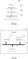
- FIG. 4A is a schematic diagram illustrating communication of an uplink data transmission method according to an embodiment of the present disclosure.
- the method includes part 401, which is specifically described as follows.
- the terminal transmits the uplink data, wherein, packet data convergence protocol sequence number (PDCP SN) of each data packet in the uplink data corresponds to a quality of service flow identification (QoS flow ID) in preset mapping relationship.
- PDCP SN packet data convergence protocol sequence number
- QoS flow ID quality of service flow identification
- the preset mapping relationship between the PDCP SN and the QoS flow ID of the data packet transmitted on the DRB1 may be as shown in FIG. 4B , the details are described as follows.
- PDCP SN 0, PDCP SN 2, PDCP SN 4...PDCP SN 2N corresponds to the QoS flow 1.
- PDCP SN 1, PDCP SN 3, PDCP SN 5...PDCP SN 2N-1 corresponds to the QoS flow 1, N is a positive integer.
- the preset mapping relationship between the PDCP SN and the QoS flow ID of the data packet transmitted on the DRB1 may be as shown in FIG. 4C , the details are described as follows.
- PDCP SN 0, PDCP SN 3, PDCP SN 6...PDCP SN 3N corresponds to the QoS flow 1.
- PDCP SN 1, PDCP SN 4, PDCP SN 7...PDCP SN 3N-2 corresponds to the QoS flow 1.
- PDCP SN 2 PDCP SN 5, PDCP SN 8...PDCP SN 3N-1 corresponds to the QoS flow 1, N is a positive integer.
- the preset mapping relationship includes the correspondence between the PDCP SN and the QoS flow ID of the data packet of the uplink data
- the transmitted data packet does not need to carry the QoS flow ID
- the terminal and the network side device only need to query the preset mapping relationship by using the PDCP SN of the data packet as a query identifier to query the preset mapping relationship, so as to know which QoS flow the data in the data packet comes from, thereby reducing the overhead of the QoS flow ID of the uplink data, which is beneficial to improve the efficiency of uplink data transmission.
- the preset mapping relationship is a correspondence between the PDCP SN and the QoS flow ID, and data in the data packet identified by the PDCP SN is derived from QoS flow identified by the QoS flow ID corresponding to the PDCP SN.
- the QoS flow identified by the QoS flow ID in the preset mapping relationship is the QoS flow of the DRB mapped to the terminal.
- the DRB is used to carry the user plane data.
- the terminal and the network side device can simultaneously establish up to eight DRBs.
- the DRB of the terminal corresponds to the PDCP stratum entity of the terminal.
- the terminal may correspond to a plurality PDCP stratum entities, e.g., 8 PDCP stratum entities, and may correspondingly support 8 DRBs.
- the network side device maps the QoS flow of the different service data to the DRB. For example, the QoS flow of the WeChat service of the terminal is mapped to the first DRB of the terminal, and the QoS flow of the video service of the terminal is mapped to the first DRB or the second DRB.
- the preset mapping relationship is determined by following manners.
- RRC radio resource control
- the preset mapping relationship used by the latter data packet may be determined according to the mapping relationship used by the previous data packet. If the previous data packet corresponds to use the mapping relationship determined by the reflective mapping, the latter data packet also corresponds to use the mapping relationship determined by the reflective mapping. If the previous data packet corresponds to use the mapping relationship determined by the flow mapping indicated by the RRC signal, the latter data packet also corresponds to use the mapping relationship determined by the flow mapping indicated by RRC signaling.
- the method further includes:
- the QoS flow ID is on the terminal side and is visible to the PDCP stratum entity of the terminal.
- an interface may be preset between the AS entity and the PDCP entity, so that the PDCP entity can obtain the QoS flow ID directly from the AS entity through the interface.
- the PDCP entity can establish a correspondence between the PDCP SN of the data packet and the QoS flow ID to form the preset mapping relationship in real time, so that the case, that the PDCP entity can't obtain the QoS flow ID of the AS entity in time and cause the data packet transmission delay, can be avoided, which is beneficial to improve the transmission efficiency of the data packet.
- the method further includes: transmitting, by the terminal, the preset mapping relationship through RRC signaling.
- FIG. 5 is a schematic diagram illustrating communication of another uplink data transmission method according to an embodiment of the present disclosure.
- the method includes part 501, which is specifically described as follows.
- the network side device receives an uplink data, wherein, packet data convergence protocol sequence number (PDCP SN) of each data packet in the uplink data corresponds to a quality of service flow identification (QoS flow ID) in preset mapping relationship.
- PDCP SN packet data convergence protocol sequence number
- QoS flow ID quality of service flow identification
- the network side device since the preset mapping relationship includes the correspondence between the PDCP SN and the QoS flow ID of the data packet of the uplink data, the transmitted data packet does not need to carry the QoS flow ID, the network side device only need to query the preset mapping relationship by using the PDCP SN of the data packet as a query identifier to query the preset mapping relationship, so as to know which QoS flow the data in the data packet comes from, thereby reducing the overhead of the QoS flow ID of the uplink data, which is beneficial to improve the efficiency of uplink data transmission.
- the preset mapping relationship is a correspondence between the PDCP SN and the QoS flow ID, and data in the data packet identified by the PDCP SN is derived from QoS flow identified by the QoS flow ID corresponding to the PDCP SN.
- the QoS flow identified by the QoS flow ID in the preset mapping relationship is the QoS flow of DRB mapped to the terminal.
- the preset mapping relationship is determined by following manners.
- the method further includes:
- the PDCP SN is visible on the network side for the PDCP stratum entity of the network side device.
- the method further includes: receiving, by the network side device, the preset mapping relationship through RRC signaling.
- the scheme of the embodiment of the disclosure is mainly introduced from the perspective of interaction between various network elements.
- the terminal and the network side device include corresponding hardware structures and/or software modules for performing the respective functions in order to implement the above functions.
- the present disclosure can be implemented in the form of hardware or a combination of hardware and computer software in combination with units and algorithm steps of various examples described in the embodiments disclosed herein. Whether a function is implemented in hardware or computer software to drive hardware depends on the specific application and design constraints of the solution. A person skilled in the art can use different methods for implementing the described functions for each particular application, but such implementation should not be considered to be beyond the scope of the present disclosure.
- the embodiments of the present disclosure may perform the division of functional units on the terminal and the network side device according to the foregoing method.
- each functional unit may be divided according to each function, or two or more functions may be integrated into one processing unit.
- the above integrated unit can be implemented in the form of hardware or in the form of a software functional unit. It should be noted that the division of the unit in the embodiment of the present disclosure is schematic, and is only a logical function division, and the actual implementation may have another division manner.
- FIG. 6A shows a possible structural diagram of the first core network device involved in the above embodiment.
- the terminal 600 includes a processing unit 602 and a communication unit 603.
- the processing unit 602 is configured to control and manage the actions of the terminal.
- the processing unit 602 is configured to support the terminal to perform step 401 in FIG. 4A and/or other processes for the techniques described herein.
- the communication unit 603 is for supporting communication between the terminal and other devices, such as communication with the network side device shown in FIG. 3 .
- the terminal may further include a storage unit 601 for storing program codes and data of the terminal.
- the processing unit 602 can be a processor or a controller, and can be, for example, a Central Processing Unit (CPU), a general-purpose processor, a Digital Signal Processor (DSP), an Application-specific Integrated Circuit (ASIC), Field Programmable Gate Array (FPGA) or other programmable logic device, transistor logic device, hardware component, or any combination thereof. It is possible to implement or carry out the various illustrative logical blocks, modules and circuits described in connection with the present disclosure.
- the processor may also be a combination of computing functions, for example, a combination including one or more microprocessors, a combination of a DSP and a microprocessor, and the like.
- the communication unit 603 may be a transceiver, a transceiver circuit, or the like, and the storage unit 601 may be a memory.
- the processing unit 602 is configured to transmit uplink data by using the communication unit 603, wherein packet data convergence protocol sequence number (PDCP SN) of each data packet in the uplink data corresponds to a quality of QoS flow ID in preset mapping relationship.
- PDCP SN packet data convergence protocol sequence number
- the preset mapping relationship is a correspondence between the PDCP SN and the QoS flow ID, and data in the data packet identified by the PDCP SN is derived from QoS flow identified by the QoS flow ID corresponding to the PDCP SN.
- the QoS flow identified by the QoS flow ID in the preset mapping relationship is the QoS flow of DRB mapped to the terminal.
- the preset mapping relationship is determined by following manners.
- the processing unit 602 is configured to obtain, by means of the communication unit 603 , from the AS entity through the PDCP stratum entity, the QoS flow ID of the QoS flow of the DRB mapped to the terminal, and establish a correspondence between the PDCP SN of the data packet and the QoS flow ID to form the preset mapping relationship.
- the processing unit 602 is configured to transmit, by means of the communication unit 603, the preset mapping relationship through the RRC signaling.
- the terminal involved in the embodiment of the present disclosure, may be the terminal shown in FIG. 4AB .
- the terminal 610 includes a processor 612, a communication interface 613, and a memory 611.
- the terminal 610 may further include a bus 614.
- the communication interface 613, the processor 612 and the memory 611 may be connected to each other through a bus 614.
- the bus 614 may be a Peripheral Component Interconnect (PCI) bus or an Extended Industry Standard Architecture (EISA) bus and so on.
- PCI Peripheral Component Interconnect
- EISA Extended Industry Standard Architecture
- the bus 614 can be categorized into an address bus, a data bus, a control bus and the like. For ease of representation, only one thick line is shown in FIG. 6B , but it does not mean that there is only one bus or one type of bus.
- the terminal shown in FIG. 6A or FIG. 6B can also be understood as a device for the terminal, which is not limited in the embodiment of the present disclosure.
- FIG. 7A shows a possible structural diagram of the first core network device involved in the above embodiment.
- the network side device 700 includes a processing unit 702 and a communication unit 703.
- the processing unit 702 is configured to control and manage the actions of the network side device.
- the processing unit 702 is configured to support the network side device to perform step 402 in FIG. 4A , step 501 in FIG. 4B , step 602 in FIG. 4C and/or other processes for the techniques described herein.
- the communication unit 703 is for supporting communication between the network side device and other devices, such as communication with the terminal shown in FIG. 3 .
- the network side device may further include a storage unit 701 for storing program codes and data of the network side device.
- the processing unit 702 can be a processor or a controller, and can be, for example, a Central Processing Unit (CPU), a general-purpose processor, a Digital Signal Processor (DSP), an Application-specific Integrated Circuit (ASIC), Field Programmable Gate Array (FPGA) or other programmable logic device, transistor logic device, hardware component, or any combination thereof. It is possible to implement or carry out the various illustrative logical blocks, modules and circuits described in connection with the present disclosure.
- the processor may also be a combination of computing functions, for example, a combination including one or more microprocessors, a combination of a DSP and a microprocessor, and the like.
- the communication unit 703 may be a transceiver, a transceiver circuit, or the like, and the storage unit 701 may be a memory.
- the processing unit 702 is configured to transmit uplink data by means of the communication unit 703, wherein packet data convergence protocol sequence number (PDCP SN) of each data packet in the uplink data corresponds to a quality of QoS flow ID in preset mapping relationship.
- PDCP SN packet data convergence protocol sequence number
- the preset mapping relationship is a correspondence between the PDCP SN and the QoS flow ID, and data in the data packet identified by the PDCP SN is derived from QoS flow identified by the QoS flow ID corresponding to the PDCP SN.
- the QoS flow identified by the QoS flow ID in the preset mapping relationship is the QoS flow of DRB mapped to the terminal.
- the preset mapping relationship is determined by following manners.
- the processing unit 702 is configured to obtain, by means of the communication unit 703, the PDCP SN from a PDCP stratum entity through an access stratum (AS) entity; and query the preset mapping relationship using the PDCP SN as a query identifier, to determine the QoS flow ID corresponding to the PDCP SN.
- AS access stratum
- the processing unit 702 is configured to transmit, by means of the communication unit 703, the preset mapping relationship through the RRC signaling.
- the network side device involved in the embodiment of the present disclosure, may be the network side device shown in FIG. 7B .
- the network side device 710 includes a processor 712, a communication interface 713, and a memory 711.
- the network side device 710 may further include a bus 715.
- the communication interface 713, the processor 712 and the memory 711 may be connected to each other through a bus 715.
- the bus 715 may be a Peripheral Component Interconnect (PCI) bus or an Extended Industry Standard Architecture (EISA) bus and so on.
- the bus 715 can be categorized into an address bus, a data bus, a control bus and the like. For ease of representation, only one thick line is shown in FIG. 7B , but it does not mean that there is only one bus or one type of bus.
- the network side device shown in FIG. 7A or FIG. 7B can also be understood as a device for the network side device, which is not limited in the embodiment of the present disclosure.
- the embodiment of the disclosure further provides a communication system, which includes the above terminal and network side device.
- the embodiment of the present disclosure further provides another terminal.
- FIG. 8 for the convenience of description, only parts related to the embodiment of the present disclosure are shown. If the specific technical details are not disclosed, please refer to the method part of the embodiment of the present disclosure.
- the terminal may be a mobile phone, a tablet computer, a Personal Digital Assistant (PDA), a Point of Sales (POS), an in-vehicle computer or the like, and a mobile phone, as the terminal, is taken as an example.
- FIG. 8 is a block diagram showing a partial structure of a mobile phone related to a terminal provided by an embodiment of the present disclosure.
- the mobile phone includes a Radio Frequency (RF) circuit 910, a memory 920, an input unit 930, a display unit 940, a sensor 950, an audio circuit 960, a Wireless Fidelity (WiFi) module 970, a processor 980 and a power supply 990 and other components.
- RF Radio Frequency
- the RF circuit 910 can be used for receiving and transmitting information.
- the RF circuit 910 includes, but is not limited to, an antenna, at least one amplifier, a transceiver, a coupler, a Low Noise Amplifier (LNA), a duplexer and the like.
- the RF circuit 910 can also communicate with the network and other devices via wireless communication.
- the above wireless communication may use any communication standard or protocol, including but not limited to Global System of Mobile communication (GSM), General Packet Radio Service (GPRS), Code Division Multiple Access (CDMA), Wideband Code Division Multiple Access (WCDMA), Long Term Evolution (LTE), E-mail, Short Messaging Service (SMS) and the like.
- GSM Global System of Mobile communication
- GPRS General Packet Radio Service
- CDMA Code Division Multiple Access
- WCDMA Wideband Code Division Multiple Access
- LTE Long Term Evolution
- E-mail Short Messaging Service
- the memory 920 can be used to store software programs and modules, and the processor 980 executes various functional applications and data processing of the mobile phone by running software programs and modules stored in the memory 920.
- the memory 920 may mainly include a storage program area and a storage data area, wherein the storage program area may store an operating system, an application required for at least one function and the like; the storage data area may store data created by usage of the mobile phone and the like.
- the memory 920 can include high speed random access memory, and can also include non-volatile memory, such as at least one magnetic disk storage device, flash memory device or other volatile solid state storage device.
- the input unit 930 can be configured to receive input numeric or character information and to generate key signal inputs related to user settings and function controls of the mobile phone.
- the input unit 930 can include a fingerprint recognition module 931 and other input devices 932.
- the fingerprint recognition module 931 can collect fingerprint data of the user thereon.
- the input unit 930 may also include other input devices 932.
- other input devices 932 may include, but are not limited to, one or more of a touch screen, a physical keyboard, function keys (such as volume control buttons, switch buttons, etc.), trackballs, mice, joysticks and the like.
- the display unit 940 can be used to display information inputted by the user or provide information to the user as well as various menus of the mobile phone.
- the display unit 940 can include a display screen 941.
- the display screen 941 can be configured in the form of a Liquid Crystal Display (LCD), an Organic Light-Emitting Diode (OLED) or the like.
- LCD Liquid Crystal Display
- OLED Organic Light-Emitting Diode
- the fingerprint recognition module 931 and the display screen 941 as two separate components to implement the input and input functions of the mobile phone, in some embodiments, the fingerprint recognition module 931 and the display screen 941 can be integrated and implemented to achieve the input and playback functions of the mobile phone.
- the mobile phone may also include at least one type of sensor 950, such as a light sensor, motion sensor and other sensors.
- the light sensor may include an ambient light sensor and a proximity sensor, wherein the ambient light sensor may adjust the brightness of the display screen 941 according to the brightness of the ambient light, and the proximity sensor may turn off the display screen 941 and/or backlight when the mobile phone moves to the ear.
- the accelerometer sensor can detect the magnitude of acceleration in all directions (usually three axes). When it is stationary, it can detect the magnitude and direction of gravity. It can be used to identify the gesture of the mobile phone (such as horizontal and vertical screen switching, related game, magnetometer gesture calibration), vibration recognition related functions (such as pedometer, tapping), and the like.
- the mobile phone can also be provided with gyroscope, barometer, hygrometer, thermometer, infrared sensor and other sensors, and are not described here for brevity.
- An audio circuit 960, a speaker 961, and a microphone 962 can provide an audio interface between the user and the mobile phone.
- the audio circuit 960 can convert the received audio data into an electrical signal, and transmit it to the speaker 961, and convert it into a sound signal for broadcast by the speaker 961; on the other hand, the microphone 962 converts the collected sound signal into an electrical signal by the audio circuit 960. It is converted to audio data after being received by the audio circuit 960, and it is processed by the audio data playback processor 980, and sent via the RF circuitry 910 to, for example, another mobile phone, or played back to the memory 920 for further processing.
- WiFi is a short-range wireless transmission technology
- the mobile phone can help users to send and receive emails, browse web pages and access streaming media, etc., through the WiFi module 970, which provides users with wireless broadband Internet access.
- FIG. 8 shows the WiFi module 970, it can be understood that it does not belong to the essential configuration of the mobile phone, and may be omitted as needed within the scope of not changing the essence of the disclosure.
- the processor 980 is the control center of the mobile phone, which connects various portions of the entire mobile phone using various interfaces and lines, by running or executing software programs and/or modules stored in the memory 920, and invoking data stored in the memory 920, executing the various functions and processing data of the mobile phone, so that the overall monitoring of the mobile phone is performed.
- the processor 980 may include one or more processing units; preferably, the processor 980 may integrate an application processor and a modem processor, wherein the application processor mainly processes an operating system, a user interface, an application and the like.
- the modem processor primarily handles wireless communications. It will be appreciated that the above described modem processor may also not be integrated into the processor 980.
- the mobile phone also includes the power supply 990 (such as a battery) for powering various components.
- the power supply can be logically connected to the processor 980 through a power management system to manage functions such as charging, discharging, and power management through the power management system.
- the mobile phone may further include a camera, a Bluetooth module and the like, and details are not described herein again.
- the process on the terminal side in each step method may be implemented based on the structure of the mobile phone.
- each unit function can be implemented based on the structure of the mobile phone.
- the steps of the method or algorithm described in the embodiments of the present disclosure may be implemented in a hardware manner, or may be implemented by a manner in which software instructions are executed by the processor.
- the software instructions may be composed of corresponding software modules, which may be stored in a Random Access Memory (RAM), a flash memory, a Read Only Memory (ROM), an Electrically EPROM (EPROM), Electrically EPROM (EEPROM), registers, hard disk, removable hard disk, compact disk read only (CD-ROM) or any other form of storage medium known in the art.
- An exemplary storage medium is coupled to the processor to enable the processor to read information from, and write information to, the storage medium.
- the storage medium can also be an part of the processor.
- the processor and the storage medium can be located in an ASIC. Additionally, the ASIC can be located in an access network device, a target network device or a core network device.
- the processor and the storage medium may also exist as a discrete component in the access network device, the target network device or the core network device.
- the functions described in the embodiments of the present disclosure may be implemented in whole or in part by software, hardware, firmware, or any combination thereof.
- software it may be implemented in whole or in part in the form of a computer program product.
- the computer program product includes one or more computer instructions.
- the processes or functions described in accordance with embodiments of the present disclosure are generated in whole or in part.
- the computer can be a general purpose computer, a special purpose computer, a computer network or other programmable device.
- the computer instructions can be stored in a computer readable storage medium or transferred from one computer readable storage medium to another computer readable storage medium, for example, the computer instructions can be transmission from a website site, computer, server or data center to another website site, computer, server, or data center by wire (eg, coaxial cable, fiber optic, Digital Subscriber Line (DSL)) or wireless (eg, infrared, wireless, microwave, etc.).
- the computer readable storage medium can be any available medium that can be accessed by a computer or a data storage device such as a server, data center or the like that includes one or more available media.
- the usable medium may be a magnetic medium (for example, a floppy disk, a hard disk, a magnetic tape), an optical medium (for example, a Digital Video Disc (DVD)), or a semiconductor medium (for example, a Solid State Disk (SSD)) etc.
- a magnetic medium for example, a floppy disk, a hard disk, a magnetic tape
- an optical medium for example, a Digital Video Disc (DVD)
- DVD Digital Video Disc
- SSD Solid State Disk
Description
- The present disclosure relates to the field of communication technologies, and more particularly, to an uplink transmission method, a terminal, a network side device and a system.
- QoS (Quality of Service) is quality of service. For network business, the quality of service includes bandwidth of transmission, delay of transmission, and packet loss rate of data. In the network, the quality of service can be improved by ensuring the bandwidth of transmission, reducing the delay of transmission and reducing the packet loss rate of data and delay jitter. Network resources are always limited, as long as there is a situation of robbing network resources, there will be requirements for the quality of service. The quality of service is relative to the network service. When the service quality of a certain type of service is guaranteed, it may damage the service quality of other services. For example, if the total bandwidth of a network is fixed, the more bandwidth a certain type of service occupies, the less bandwidth that other services can use, which may affect the use of other services. Therefore, network managers need to rationally plan and allocate network resources according to the characteristics of various services, so that network resources can be efficiently utilized.
- The QoS of the 5th-Generation (5G) new radio (NR) mainly includes two parts, non-access stratum mapping (NAS mapping) and access stratum mapping (AS mapping), which includes a process of mapping data packets from Internet protocol (IP flow) to QoS flow, and mapping QoS flow to data radio bear (DRB). As shown in
FIG. 1 , according to the latest development of the 3rd Generation Partnership Project (3GPP) conference, the QoS of the 5G NR needs to establish a protocol data unit session (PDU session), the PDU session contains the QoS flow mapped by multiple IP flow, and packets in each QoS flow carry the QoS flow identification (QoS flow ID). For the uplink data, the mapping of the QoS flow to the DRB is determined according to the downlink data mapping rule, and each packet needs to carry the QoS flow ID to complete the mapping. For the uplink data, the mapping from the DRB to the QoS flow at the receiving end needs to be judged according to the QoS flow ID. This requires the QoS flow ID carried on each packet. However, the QoS flow ID carried on each packet obviously increases the extra resource waste. Related technologies are known fromEP 3 355 641A1 - The invention is defined by the independent claims. Embodiments of the present disclosure provide an uplink data transmission method, a terminal, a network side device, and a computer readable storage medium so as to reduce the overhead of the QoS flow ID of the uplink data and improve the uplink data transmission efficiency.
- In the present disclosure, since a preset mapping relationship includes a correspondence between a PDCP SN and a QoS flow ID of the data packet of the uplink data, the transmitted data packet does not need to carry the QoS flow ID, the terminal and the network side device only need to query the preset mapping relationship by using the PDCP SN of the data packet as a query identifier to query the preset mapping relationship, so as to know which QoS flow the data in the data packet comes from, thereby reducing the overhead of the QoS flow ID of the uplink data, which is beneficial to improve the efficiency of uplink data transmission.
- The drawings used in the embodiments or the description of the prior art will be briefly introduced below.
-
FIG. 1 is a schematic diagram illustrating a PDU session established by QoS of a 5G NR; -
FIG. 2 is a block diagram illustrating a protocol stack of a 5G NR; -
FIG. 3 is a schematic diagram illustrating network architecture of an exemplary mobile communication system according to an embodiment of the present disclosure; -
FIG. 4A is a schematic diagram illustrating communication of an uplink data transmission method according to an embodiment of the present disclosure; -
FIG. 4B is a schematic diagram illustrating a preset mapping relationship according to an embodiment of the present disclosure; -
FIG. 4C is a schematic diagram illustrating another preset mapping relationship according to an embodiment of the present disclosure; -
FIG. 5 is a schematic diagram illustrating communication of another uplink data transmission method according to an embodiment of the present disclosure; -
FIG. 6A is a block diagram illustrating a terminal according to an embodiment of the present disclosure; -
FIG. 6B is a block diagram illustrating another terminal according to an embodiment of the present disclosure; -
FIG. 7A is a block diagram illustrating a network side device according to an embodiment of the present disclosure; -
FIG. 7B is a block diagram illustrating another network side device according to an embodiment of the present disclosure; -
FIG. 8 is a block diagram illustrating another terminal according to an embodiment of the present disclosure. - The technical solutions in the embodiments of the present disclosure will be described below with reference to the accompanying drawings.
- As shown in
FIG. 2 , the access stratum (AS) of the 5G NR is used to complete the mapping from the QoS flow to the DRB according to the corresponding QoS flow ID. The AS mainly includes the following three functions: (1) the QoS flow routing to the DRB; (2) the QoS flow ID encapsulation in downlink data; (3) the QoS flow ID encapsulation in uplink data. - Referring to
FIG. 3, FIG. 3 is a schematic diagram illustrating network architecture of an exemplary mobile communication system according to an embodiment of the present disclosure. The network architecture includes a network side device and a terminal. When the terminal accesses the mobile communication network provided by the network side device, the terminal and the network side device can communicate through the wireless link. The mobile communication system may be, for example, a 5G NR mobile communication system or the like. The network side device may be, for example, a base station in 5G network. In embodiments of the present disclosure, the terms "network" and "system" are often used interchangeably, and those skilled in the art can understand the meaning thereof. The terminal involved in the embodiments of the present disclosure may include various handheld devices, in-vehicle devices, wearable devices, computing devices, or other processing devices connected to the wireless modem, and various forms of user equipment (UE), mobile station (MS), terminal device and the like. For convenience of description, the devices mentioned above are collectively referred to as terminals. - Referring to
FIG. 4A, FIG. 4A is a schematic diagram illustrating communication of an uplink data transmission method according to an embodiment of the present disclosure. The method includespart 401, which is specifically described as follows. - In the
part 401, the terminal transmits the uplink data, wherein, packet data convergence protocol sequence number (PDCP SN) of each data packet in the uplink data corresponds to a quality of service flow identification (QoS flow ID) in preset mapping relationship. - For example, if the QoS flow of the DRB1 mapped to the terminal includes
QoS flow 1 andQoS flow 2, the preset mapping relationship between the PDCP SN and the QoS flow ID of the data packet transmitted on the DRB1 may be as shown inFIG. 4B , the details are described as follows. - PDCP SN 0, PDCP
SN 2, PDCP SN 4...PDCP SN 2N corresponds to theQoS flow 1. - PDCP
SN 1, PDCPSN 3, PDCP SN 5...PDCP SN 2N-1 corresponds to theQoS flow 1, N is a positive integer. - For example, if the QoS flow of the DRB1 mapped to the terminal includes
QoS flow 1,QoS flow 2 andQoS flow 3, the preset mapping relationship between the PDCP SN and the QoS flow ID of the data packet transmitted on the DRB1 may be as shown inFIG. 4C , the details are described as follows. - PDCP SN 0,
PDCP SN 3, PDCP SN 6...PDCP SN 3N corresponds to theQoS flow 1. -
PDCP SN 1, PDCP SN 4, PDCP SN 7...PDCP SN 3N-2 corresponds to theQoS flow 1. -
PDCP SN 2, PDCP SN 5, PDCP SN 8...PDCP SN 3N-1 corresponds to theQoS flow 1, N is a positive integer. - It can be seen that, in the embodiment of the present disclosure, since the preset mapping relationship includes the correspondence between the PDCP SN and the QoS flow ID of the data packet of the uplink data, the transmitted data packet does not need to carry the QoS flow ID, the terminal and the network side device only need to query the preset mapping relationship by using the PDCP SN of the data packet as a query identifier to query the preset mapping relationship, so as to know which QoS flow the data in the data packet comes from, thereby reducing the overhead of the QoS flow ID of the uplink data, which is beneficial to improve the efficiency of uplink data transmission.
- In one possible example, the preset mapping relationship is a correspondence between the PDCP SN and the QoS flow ID, and data in the data packet identified by the PDCP SN is derived from QoS flow identified by the QoS flow ID corresponding to the PDCP SN.
- In one possible example, the QoS flow identified by the QoS flow ID in the preset mapping relationship is the QoS flow of the DRB mapped to the terminal.
- Wherein, the DRB is used to carry the user plane data. According to the QoS, the terminal and the network side device can simultaneously establish up to eight DRBs. The DRB of the terminal corresponds to the PDCP stratum entity of the terminal. The terminal may correspond to a plurality PDCP stratum entities, e.g., 8 PDCP stratum entities, and may correspondingly support 8 DRBs. When the QoS flow of different service data on the network side is transmitted, the network side device maps the QoS flow of the different service data to the DRB. For example, the QoS flow of the WeChat service of the terminal is mapped to the first DRB of the terminal, and the QoS flow of the video service of the terminal is mapped to the first DRB or the second DRB.
- In one possible example, the preset mapping relationship is determined by following manners.
- It may be determined by the reflective mapping of the QoS.
- Or, it may be determined by the flow mapping indicated by the radio resource control (RRC) signaling.
- Wherein, for the two data packets transmitted on the same DRB, the preset mapping relationship used by the latter data packet may be determined according to the mapping relationship used by the previous data packet. If the previous data packet corresponds to use the mapping relationship determined by the reflective mapping, the latter data packet also corresponds to use the mapping relationship determined by the reflective mapping. If the previous data packet corresponds to use the mapping relationship determined by the flow mapping indicated by the RRC signal, the latter data packet also corresponds to use the mapping relationship determined by the flow mapping indicated by RRC signaling.
- In one possible example, the method further includes:
- obtaining, by the terminal, from an access stratum (AS) entity through a PDCP stratum entity, the QoS flow ID of the QoS flow of the DRB mapped to the terminal; and
- establishing, by the terminal, a correspondence between the PDCP SN of the data packet and the QoS flow ID to form the preset mapping relationship.
- Wherein, the QoS flow ID is on the terminal side and is visible to the PDCP stratum entity of the terminal. In a specific implementation, an interface may be preset between the AS entity and the PDCP entity, so that the PDCP entity can obtain the QoS flow ID directly from the AS entity through the interface.
- It can be seen that, in this example, since the PDCP stratum can directly obtain the QoS flow ID of the QoS flow of the DRB mapped to the terminal from the AS entity, and since the PDCP SN of the data packet is directly configured by the PDCP entity, the PDCP entity can establish a correspondence between the PDCP SN of the data packet and the QoS flow ID to form the preset mapping relationship in real time, so that the case, that the PDCP entity can't obtain the QoS flow ID of the AS entity in time and cause the data packet transmission delay, can be avoided, which is beneficial to improve the transmission efficiency of the data packet.
- In one possible example, the method further includes:
transmitting, by the terminal, the preset mapping relationship through RRC signaling. - Referring to
FIG. 5, FIG. 5 is a schematic diagram illustrating communication of another uplink data transmission method according to an embodiment of the present disclosure. The method includespart 501, which is specifically described as follows. - In the
part 501, the network side device receives an uplink data, wherein, packet data convergence protocol sequence number (PDCP SN) of each data packet in the uplink data corresponds to a quality of service flow identification (QoS flow ID) in preset mapping relationship. - It can be seen that, in the embodiment of the present disclosure, since the preset mapping relationship includes the correspondence between the PDCP SN and the QoS flow ID of the data packet of the uplink data, the transmitted data packet does not need to carry the QoS flow ID, the network side device only need to query the preset mapping relationship by using the PDCP SN of the data packet as a query identifier to query the preset mapping relationship, so as to know which QoS flow the data in the data packet comes from, thereby reducing the overhead of the QoS flow ID of the uplink data, which is beneficial to improve the efficiency of uplink data transmission.
- In a possible embodiment, the preset mapping relationship is a correspondence between the PDCP SN and the QoS flow ID, and data in the data packet identified by the PDCP SN is derived from QoS flow identified by the QoS flow ID corresponding to the PDCP SN.
- In a possible embodiment, the QoS flow identified by the QoS flow ID in the preset mapping relationship is the QoS flow of DRB mapped to the terminal.
- In a possible embodiment, the preset mapping relationship is determined by following manners.
- It may be determined by the reflective mapping of the QoS.
- Or, It may be determined by the flow mapping indicated by the RRC signaling.
- In a possible embodiment, the method further includes:
- obtaining, by the network side device, the PDCP SN from a PDCP stratum entity through an access stratum (AS) entity; and
- querying, by the network side device, the preset mapping relationship using the PDCP SN as a query identifier, to determine the QoS flow ID corresponding to the PDCP SN.
- Wherein, the PDCP SN is visible on the network side for the PDCP stratum entity of the network side device.
- In one possible example, the method further includes:
receiving, by the network side device, the preset mapping relationship through RRC signaling. - The scheme of the embodiment of the disclosure is mainly introduced from the perspective of interaction between various network elements. It can be understood that the terminal and the network side device include corresponding hardware structures and/or software modules for performing the respective functions in order to implement the above functions. Those skilled in the art will readily appreciate that the present disclosure can be implemented in the form of hardware or a combination of hardware and computer software in combination with units and algorithm steps of various examples described in the embodiments disclosed herein. Whether a function is implemented in hardware or computer software to drive hardware depends on the specific application and design constraints of the solution. A person skilled in the art can use different methods for implementing the described functions for each particular application, but such implementation should not be considered to be beyond the scope of the present disclosure.
- The embodiments of the present disclosure may perform the division of functional units on the terminal and the network side device according to the foregoing method. For example, each functional unit may be divided according to each function, or two or more functions may be integrated into one processing unit. The above integrated unit can be implemented in the form of hardware or in the form of a software functional unit. It should be noted that the division of the unit in the embodiment of the present disclosure is schematic, and is only a logical function division, and the actual implementation may have another division manner.
- In the case of adopting an integrated unit,
FIG. 6A shows a possible structural diagram of the first core network device involved in the above embodiment. The terminal 600 includes aprocessing unit 602 and acommunication unit 603. Theprocessing unit 602 is configured to control and manage the actions of the terminal. For example, theprocessing unit 602 is configured to support the terminal to performstep 401 inFIG. 4A and/or other processes for the techniques described herein. Thecommunication unit 603 is for supporting communication between the terminal and other devices, such as communication with the network side device shown inFIG. 3 . The terminal may further include astorage unit 601 for storing program codes and data of the terminal. - Wherein, the
processing unit 602 can be a processor or a controller, and can be, for example, a Central Processing Unit (CPU), a general-purpose processor, a Digital Signal Processor (DSP), an Application-specific Integrated Circuit (ASIC), Field Programmable Gate Array (FPGA) or other programmable logic device, transistor logic device, hardware component, or any combination thereof. It is possible to implement or carry out the various illustrative logical blocks, modules and circuits described in connection with the present disclosure. The processor may also be a combination of computing functions, for example, a combination including one or more microprocessors, a combination of a DSP and a microprocessor, and the like. Thecommunication unit 603 may be a transceiver, a transceiver circuit, or the like, and thestorage unit 601 may be a memory. - Wherein, the
processing unit 602 is configured to transmit uplink data by using thecommunication unit 603, wherein packet data convergence protocol sequence number (PDCP SN) of each data packet in the uplink data corresponds to a quality of QoS flow ID in preset mapping relationship. - In a possible example, the preset mapping relationship is a correspondence between the PDCP SN and the QoS flow ID, and data in the data packet identified by the PDCP SN is derived from QoS flow identified by the QoS flow ID corresponding to the PDCP SN.
- In a possible example, the QoS flow identified by the QoS flow ID in the preset mapping relationship is the QoS flow of DRB mapped to the terminal.
- In a possible example, the preset mapping relationship is determined by following manners.
- It may be determined by the reflective mapping of the QoS.
- Or, it may be determined by the flow mapping indicated by the RRC signaling.
- In a possible example, the
processing unit 602 is configured to obtain, by means of thecommunication unit 603 , from the AS entity through the PDCP stratum entity, the QoS flow ID of the QoS flow of the DRB mapped to the terminal, and establish a correspondence between the PDCP SN of the data packet and the QoS flow ID to form the preset mapping relationship. - In a possible example, the
processing unit 602 is configured to transmit, by means of thecommunication unit 603, the preset mapping relationship through the RRC signaling. - When the
processing unit 602 is a processor, thecommunication unit 603 is a communication interface, and thestorage unit 601 is a memory, the terminal, involved in the embodiment of the present disclosure, may be the terminal shown inFIG. 4AB . - Referring to
FIG. 6B , the terminal 610 includes aprocessor 612, acommunication interface 613, and amemory 611. Optionally, the terminal 610 may further include abus 614. Thecommunication interface 613, theprocessor 612 and thememory 611 may be connected to each other through abus 614. Thebus 614 may be a Peripheral Component Interconnect (PCI) bus or an Extended Industry Standard Architecture (EISA) bus and so on. Thebus 614 can be categorized into an address bus, a data bus, a control bus and the like. For ease of representation, only one thick line is shown inFIG. 6B , but it does not mean that there is only one bus or one type of bus. - The terminal shown in
FIG. 6A or FIG. 6B can also be understood as a device for the terminal, which is not limited in the embodiment of the present disclosure. - In the case of adopting an integrated unit,
FIG. 7A shows a possible structural diagram of the first core network device involved in the above embodiment. Thenetwork side device 700 includes aprocessing unit 702 and acommunication unit 703. Theprocessing unit 702 is configured to control and manage the actions of the network side device. For example, theprocessing unit 702 is configured to support the network side device to perform step 402 inFIG. 4A ,step 501 inFIG. 4B ,step 602 inFIG. 4C and/or other processes for the techniques described herein. Thecommunication unit 703 is for supporting communication between the network side device and other devices, such as communication with the terminal shown inFIG. 3 . The network side device may further include astorage unit 701 for storing program codes and data of the network side device. - Wherein, the
processing unit 702 can be a processor or a controller, and can be, for example, a Central Processing Unit (CPU), a general-purpose processor, a Digital Signal Processor (DSP), an Application-specific Integrated Circuit (ASIC), Field Programmable Gate Array (FPGA) or other programmable logic device, transistor logic device, hardware component, or any combination thereof. It is possible to implement or carry out the various illustrative logical blocks, modules and circuits described in connection with the present disclosure. The processor may also be a combination of computing functions, for example, a combination including one or more microprocessors, a combination of a DSP and a microprocessor, and the like. Thecommunication unit 703 may be a transceiver, a transceiver circuit, or the like, and thestorage unit 701 may be a memory. - Wherein, the
processing unit 702 is configured to transmit uplink data by means of thecommunication unit 703, wherein packet data convergence protocol sequence number (PDCP SN) of each data packet in the uplink data corresponds to a quality of QoS flow ID in preset mapping relationship. - In a possible example, the preset mapping relationship is a correspondence between the PDCP SN and the QoS flow ID, and data in the data packet identified by the PDCP SN is derived from QoS flow identified by the QoS flow ID corresponding to the PDCP SN.
- In a possible example, the QoS flow identified by the QoS flow ID in the preset mapping relationship is the QoS flow of DRB mapped to the terminal.
- In a possible example, the preset mapping relationship is determined by following manners.
- It may be determined by the reflective mapping of the QoS.
- Or, It may be determined by the flow mapping indicated by the RRC signaling.
- In a possible example, the
processing unit 702 is configured to obtain, by means of thecommunication unit 703, the PDCP SN from a PDCP stratum entity through an access stratum (AS) entity; and query the preset mapping relationship using the PDCP SN as a query identifier, to determine the QoS flow ID corresponding to the PDCP SN. - In a possible example, the
processing unit 702 is configured to transmit, by means of thecommunication unit 703, the preset mapping relationship through the RRC signaling. - When the
processing unit 702 is a processor, thecommunication unit 703 is a communication interface, and thestorage unit 701 is a memory, the network side device, involved in the embodiment of the present disclosure, may be the network side device shown inFIG. 7B . - Referring to
FIG. 7B , the network side device 710 includes aprocessor 712, acommunication interface 713, and amemory 711. Optionally, the network side device 710 may further include a bus 715. Thecommunication interface 713, theprocessor 712 and thememory 711 may be connected to each other through a bus 715. The bus 715 may be a Peripheral Component Interconnect (PCI) bus or an Extended Industry Standard Architecture (EISA) bus and so on. The bus 715 can be categorized into an address bus, a data bus, a control bus and the like. For ease of representation, only one thick line is shown inFIG. 7B , but it does not mean that there is only one bus or one type of bus. - The network side device shown in
FIG. 7A or FIG. 7B can also be understood as a device for the network side device, which is not limited in the embodiment of the present disclosure. - The embodiment of the disclosure further provides a communication system, which includes the above terminal and network side device.
- The embodiment of the present disclosure further provides another terminal. As shown in
FIG. 8 , for the convenience of description, only parts related to the embodiment of the present disclosure are shown. If the specific technical details are not disclosed, please refer to the method part of the embodiment of the present disclosure. The terminal may be a mobile phone, a tablet computer, a Personal Digital Assistant (PDA), a Point of Sales (POS), an in-vehicle computer or the like, and a mobile phone, as the terminal, is taken as an example. -
FIG. 8 is a block diagram showing a partial structure of a mobile phone related to a terminal provided by an embodiment of the present disclosure. Referring toFIG. 8 , the mobile phone includes a Radio Frequency (RF)circuit 910, amemory 920, aninput unit 930, adisplay unit 940, asensor 950, anaudio circuit 960, a Wireless Fidelity (WiFi)module 970, aprocessor 980 and apower supply 990 and other components. It will be understood by those skilled in the art that the structure of the mobile phone shown inFIG. 8 does not constitute a limitation to the mobile phone, and may include more or less components than those illustrated, or some components may be combined, or different component arrangements. - The specific components of the mobile phone will be specifically introduced below with reference to
FIG. 8 . - The
RF circuit 910 can be used for receiving and transmitting information. Generally, theRF circuit 910 includes, but is not limited to, an antenna, at least one amplifier, a transceiver, a coupler, a Low Noise Amplifier (LNA), a duplexer and the like. In addition, theRF circuit 910 can also communicate with the network and other devices via wireless communication. The above wireless communication may use any communication standard or protocol, including but not limited to Global System of Mobile communication (GSM), General Packet Radio Service (GPRS), Code Division Multiple Access (CDMA), Wideband Code Division Multiple Access (WCDMA), Long Term Evolution (LTE), E-mail, Short Messaging Service (SMS) and the like. - The
memory 920 can be used to store software programs and modules, and theprocessor 980 executes various functional applications and data processing of the mobile phone by running software programs and modules stored in thememory 920. Thememory 920 may mainly include a storage program area and a storage data area, wherein the storage program area may store an operating system, an application required for at least one function and the like; the storage data area may store data created by usage of the mobile phone and the like. Moreover, thememory 920 can include high speed random access memory, and can also include non-volatile memory, such as at least one magnetic disk storage device, flash memory device or other volatile solid state storage device. - The
input unit 930 can be configured to receive input numeric or character information and to generate key signal inputs related to user settings and function controls of the mobile phone. Specifically, theinput unit 930 can include afingerprint recognition module 931 andother input devices 932. Thefingerprint recognition module 931 can collect fingerprint data of the user thereon. In addition to thefingerprint recognition module 931, theinput unit 930 may also includeother input devices 932. Specifically,other input devices 932 may include, but are not limited to, one or more of a touch screen, a physical keyboard, function keys (such as volume control buttons, switch buttons, etc.), trackballs, mice, joysticks and the like. - The
display unit 940 can be used to display information inputted by the user or provide information to the user as well as various menus of the mobile phone. Thedisplay unit 940 can include adisplay screen 941. Optionally, thedisplay screen 941 can be configured in the form of a Liquid Crystal Display (LCD), an Organic Light-Emitting Diode (OLED) or the like. Although inFIG. 8 , thefingerprint recognition module 931 and thedisplay screen 941 as two separate components to implement the input and input functions of the mobile phone, in some embodiments, thefingerprint recognition module 931 and thedisplay screen 941 can be integrated and implemented to achieve the input and playback functions of the mobile phone. - The mobile phone may also include at least one type of
sensor 950, such as a light sensor, motion sensor and other sensors. Specifically, the light sensor may include an ambient light sensor and a proximity sensor, wherein the ambient light sensor may adjust the brightness of thedisplay screen 941 according to the brightness of the ambient light, and the proximity sensor may turn off thedisplay screen 941 and/or backlight when the mobile phone moves to the ear. As a kind of motion sensor, the accelerometer sensor can detect the magnitude of acceleration in all directions (usually three axes). When it is stationary, it can detect the magnitude and direction of gravity. It can be used to identify the gesture of the mobile phone (such as horizontal and vertical screen switching, related game, magnetometer gesture calibration), vibration recognition related functions (such as pedometer, tapping), and the like. The mobile phone can also be provided with gyroscope, barometer, hygrometer, thermometer, infrared sensor and other sensors, and are not described here for brevity. - An
audio circuit 960, aspeaker 961, and amicrophone 962 can provide an audio interface between the user and the mobile phone. Theaudio circuit 960 can convert the received audio data into an electrical signal, and transmit it to thespeaker 961, and convert it into a sound signal for broadcast by thespeaker 961; on the other hand, themicrophone 962 converts the collected sound signal into an electrical signal by theaudio circuit 960. It is converted to audio data after being received by theaudio circuit 960, and it is processed by the audiodata playback processor 980, and sent via theRF circuitry 910 to, for example, another mobile phone, or played back to thememory 920 for further processing. - WiFi is a short-range wireless transmission technology, and the mobile phone can help users to send and receive emails, browse web pages and access streaming media, etc., through the
WiFi module 970, which provides users with wireless broadband Internet access. AlthoughFIG. 8 shows theWiFi module 970, it can be understood that it does not belong to the essential configuration of the mobile phone, and may be omitted as needed within the scope of not changing the essence of the disclosure. - The
processor 980 is the control center of the mobile phone, which connects various portions of the entire mobile phone using various interfaces and lines, by running or executing software programs and/or modules stored in thememory 920, and invoking data stored in thememory 920, executing the various functions and processing data of the mobile phone, so that the overall monitoring of the mobile phone is performed. Optionally, theprocessor 980 may include one or more processing units; preferably, theprocessor 980 may integrate an application processor and a modem processor, wherein the application processor mainly processes an operating system, a user interface, an application and the like. The modem processor primarily handles wireless communications. It will be appreciated that the above described modem processor may also not be integrated into theprocessor 980. - The mobile phone also includes the power supply 990 (such as a battery) for powering various components. Preferably, the power supply can be logically connected to the
processor 980 through a power management system to manage functions such as charging, discharging, and power management through the power management system. - Although not shown, the mobile phone may further include a camera, a Bluetooth module and the like, and details are not described herein again.
- In the foregoing embodiment shown in
FIG. 4A andFIG. 5 , the process on the terminal side in each step method may be implemented based on the structure of the mobile phone. - In the foregoing embodiments shown in
FIG. 6A and FIG. 6B , each unit function can be implemented based on the structure of the mobile phone. - The steps of the method or algorithm described in the embodiments of the present disclosure may be implemented in a hardware manner, or may be implemented by a manner in which software instructions are executed by the processor. The software instructions may be composed of corresponding software modules, which may be stored in a Random Access Memory (RAM), a flash memory, a Read Only Memory (ROM), an Electrically EPROM (EPROM), Electrically EPROM (EEPROM), registers, hard disk, removable hard disk, compact disk read only (CD-ROM) or any other form of storage medium known in the art. An exemplary storage medium is coupled to the processor to enable the processor to read information from, and write information to, the storage medium. Of course, the storage medium can also be an part of the processor. The processor and the storage medium can be located in an ASIC. Additionally, the ASIC can be located in an access network device, a target network device or a core network device. Of course, the processor and the storage medium may also exist as a discrete component in the access network device, the target network device or the core network device.
- Those skilled in the art should appreciate that in one or more of the above examples, the functions described in the embodiments of the present disclosure may be implemented in whole or in part by software, hardware, firmware, or any combination thereof. When implemented in software, it may be implemented in whole or in part in the form of a computer program product. The computer program product includes one or more computer instructions. When the computer program instructions are loaded and executed on a computer, the processes or functions described in accordance with embodiments of the present disclosure are generated in whole or in part. The computer can be a general purpose computer, a special purpose computer, a computer network or other programmable device. The computer instructions can be stored in a computer readable storage medium or transferred from one computer readable storage medium to another computer readable storage medium, for example, the computer instructions can be transmission from a website site, computer, server or data center to another website site, computer, server, or data center by wire (eg, coaxial cable, fiber optic, Digital Subscriber Line (DSL)) or wireless (eg, infrared, wireless, microwave, etc.). The computer readable storage medium can be any available medium that can be accessed by a computer or a data storage device such as a server, data center or the like that includes one or more available media. The usable medium may be a magnetic medium (for example, a floppy disk, a hard disk, a magnetic tape), an optical medium (for example, a Digital Video Disc (DVD)), or a semiconductor medium (for example, a Solid State Disk (SSD)) etc.
- The specific embodiments of the present disclosure have been described in detail with reference to the embodiments of the embodiments of the present disclosure.
Claims (11)
- An uplink data transmission method, comprising:transmitting, by a terminal, a preset mapping relationship through radio resource control, RRC, signaling; andtransmitting (401) uplink data by the terminal, wherein, a packet data convergenceprotocol, PDCP, sequence number, SN, of each data packet in the uplink data corresponds to one quality of service, QoS, flow identification, ID, in the preset mapping relationship, and the each data packet does not need to carry the QoS flow ID,wherein the preset mapping relationship is a correspondence between the PDCP SN and the QoS flow ID, and data in the data packet identified by the PDCP SN is derived from a QoS flow identified by the QoS flow ID corresponding to the PDCP SN.
- The method according to claim 1, wherein the QoS flow identified by the QoS flow ID in the preset mapping relationship is the QoS flow of a data radio bearer, DRB, mapped to the terminal.
- The method according to claim 1 or 2, wherein the preset mapping relationship is determined by:a reflective mapping of QoS; ora flow mapping indicated by RRC signaling.
- The method according to any one of claims 1-3, further comprising:obtaining, by the terminal, from an access stratum, AS, entity through a PDCP stratum entity, the QoS flow ID of the QoS flow of a DRB mapped to the terminal; andestablishing, by the terminal, a correspondence between the PDCP SN of the data packet and the QoS flow ID to form the preset mapping relationship.
- An uplink data transmission method, comprising:receiving, by a network side device, a preset mapping relationship through radio resource control, RRC, signaling; andreceiving (501) an uplink data by the network side device, wherein, a packet data convergence protocol, PDCP, sequence number, SN, of each data packet in the uplink data corresponds to one quality of service, QoS, flow identification, ID, in the preset mapping relationship, and the each data packet does not need to carry the QoS flow ID,wherein the preset mapping relationship is a correspondence between the PDCP SN and the QoS flow ID, and data in the data packet identified by the PDCP SN is derived from a QoS flow identified by the QoS flow ID corresponding to the PDCP SN.
- The method according to claim 5, wherein the QoS flow identified by the QoS flow ID in the preset mapping relationship is the QoS flow of a data radio bearer, DRB, mapped to the terminal.
- The method according to claim 5 or 6, wherein the preset mapping relationship is determined by:a reflective mapping of QoS; ora flow mapping indicated by RRC signaling.
- The method according to any one of claims 5-7, further comprising:obtaining, by the network side device, the PDCP SN from a PDCP stratum entity through an access stratum, AS, entity; andquerying, by the network side device, the preset mapping relationship using the PDCP SN as a query identifier, to determine the QoS flow ID corresponding to the PDCP SN.
- A terminal, comprising a processor (612), a memory (611) and a transceiver (613), wherein the processor (612) is in communication with the memory (611) and the transceiver (613);
the memory (611) is configured to store program codes and data, and the processor (612) is configured to invoke the program codes and the data in the memory (611) to perform the method according to any one of claims 1-4. - A network side device, comprising a processor (712), a memory (711) and a transceiver (713), wherein the processor (712) is in communication with the memory (711) and the transceiver (713);
the memory (711) is configured to store program codes and data, and the processor (712) is configured to invoke the program codes and the data in the memory (711) to perform the method according to any one of claims 5-8. - A computer readable storage medium, wherein the computer readable storage medium stores instructions, when being executed on a computer, the computer is caused to perform the method according to any one of claims 1-8.
Applications Claiming Priority (1)
| Application Number | Priority Date | Filing Date | Title |
|---|---|---|---|
| PCT/CN2017/077867 WO2018170833A1 (en) | 2017-03-23 | 2017-03-23 | Uplink data transmission method, terminal, network side device and system |
Publications (3)
| Publication Number | Publication Date |
|---|---|
| EP3550883A1 EP3550883A1 (en) | 2019-10-09 |
| EP3550883A4 EP3550883A4 (en) | 2019-12-25 |
| EP3550883B1 true EP3550883B1 (en) | 2021-08-04 |
Family
ID=63584966
Family Applications (1)
| Application Number | Title | Priority Date | Filing Date |
|---|---|---|---|
| EP17902349.4A Active EP3550883B1 (en) | 2017-03-23 | 2017-03-23 | Uplink data transmission method, terminal, network side device and system |
Country Status (4)
| Country | Link |
|---|---|
| US (1) | US10959124B2 (en) |
| EP (1) | EP3550883B1 (en) |
| CN (1) | CN110036661B (en) |
| WO (1) | WO2018170833A1 (en) |
Families Citing this family (15)
| Publication number | Priority date | Publication date | Assignee | Title |
|---|---|---|---|---|
| US10454714B2 (en) | 2013-07-10 | 2019-10-22 | Nicira, Inc. | Method and system of overlay flow control |
| CN108809590B (en) * | 2017-05-05 | 2019-10-15 | 中国移动通信有限公司研究院 | A kind of data transmission method and new access sub-layer entities |
| US10999100B2 (en) | 2017-10-02 | 2021-05-04 | Vmware, Inc. | Identifying multiple nodes in a virtual network defined over a set of public clouds to connect to an external SAAS provider |
| US11102032B2 (en) | 2017-10-02 | 2021-08-24 | Vmware, Inc. | Routing data message flow through multiple public clouds |
| US11115480B2 (en) | 2017-10-02 | 2021-09-07 | Vmware, Inc. | Layer four optimization for a virtual network defined over public cloud |
| US11223514B2 (en) | 2017-11-09 | 2022-01-11 | Nicira, Inc. | Method and system of a dynamic high-availability mode based on current wide area network connectivity |
| US11252106B2 (en) | 2019-08-27 | 2022-02-15 | Vmware, Inc. | Alleviating congestion in a virtual network deployed over public clouds for an entity |
| CN112996043A (en) * | 2019-12-16 | 2021-06-18 | 中国移动通信有限公司研究院 | Interlayer mapping method and device of communication device |
| US20210234804A1 (en) | 2020-01-24 | 2021-07-29 | Vmware, Inc. | Accurate traffic steering between links through sub-path path quality metrics |
| CN113271551B (en) * | 2020-02-17 | 2022-07-05 | 大唐移动通信设备有限公司 | Data stream transmission method, terminal and network side equipment |
| US11601356B2 (en) | 2020-12-29 | 2023-03-07 | Vmware, Inc. | Emulating packet flows to assess network links for SD-WAN |
| CN116783874A (en) | 2021-01-18 | 2023-09-19 | Vm维尔股份有限公司 | Network aware load balancing |
| CN115915437A (en) * | 2021-08-13 | 2023-04-04 | 维沃移动通信有限公司 | Data transmission method, device, terminal and network side equipment |
| US11943146B2 (en) | 2021-10-01 | 2024-03-26 | VMware LLC | Traffic prioritization in SD-WAN |
| US11909815B2 (en) | 2022-06-06 | 2024-02-20 | VMware LLC | Routing based on geolocation costs |
Family Cites Families (13)
| Publication number | Priority date | Publication date | Assignee | Title |
|---|---|---|---|---|
| CN102026398B (en) | 2009-09-15 | 2013-02-13 | 普天信息技术研究院有限公司 | Method and device for realizing packet data convergence protocol of LTE relay system |
| CN103634893B (en) | 2012-08-20 | 2016-06-22 | 中兴通讯股份有限公司 | PDCP sequence number synchronization method and device |
| IN2015DN03255A (en) | 2012-11-09 | 2015-10-09 | Ericsson Telefon Ab L M | |
| WO2014092626A1 (en) * | 2012-12-14 | 2014-06-19 | Telefonaktiebolaget L M Ericsson (Publ) | Node apparatus and method for establishing auxiliary bearers |
| US9722929B2 (en) * | 2013-04-08 | 2017-08-01 | Telefonaktiebolaget Lm Ericsson (Publ) | Congestion aware throughput targets |
| CN105813213B (en) * | 2014-12-31 | 2019-11-12 | 中国电信股份有限公司 | Method, base station and the system of data are transmitted in dual link scheme |
| CN104683262B (en) | 2015-01-30 | 2018-02-02 | 大唐移动通信设备有限公司 | The processing method and equipment of a kind of packet |
| CN104735728A (en) | 2015-04-10 | 2015-06-24 | 宇龙计算机通信科技(深圳)有限公司 | Service data flow transmission method and system |
| WO2016191963A1 (en) | 2015-05-29 | 2016-12-08 | 华为技术有限公司 | Method for bearer establishment, user equipment and base station |
| CN115474245A (en) | 2015-06-30 | 2022-12-13 | 华为技术有限公司 | Data transmission method, wireless network node and communication system |
| CN106357548B (en) | 2016-09-18 | 2019-06-11 | 京信通信系统(中国)有限公司 | The method of reseptance and system of PDCP data packet |
| CN106453138B (en) | 2016-11-25 | 2020-03-06 | 新华三技术有限公司 | Message processing method and device |
| US20180213540A1 (en) * | 2017-01-25 | 2018-07-26 | Acer Incorporated | Method of mapping data packets and related apparatuses using the same |
-
2017
- 2017-03-23 US US16/475,350 patent/US10959124B2/en active Active
- 2017-03-23 WO PCT/CN2017/077867 patent/WO2018170833A1/en unknown
- 2017-03-23 CN CN201780075282.3A patent/CN110036661B/en active Active
- 2017-03-23 EP EP17902349.4A patent/EP3550883B1/en active Active
Non-Patent Citations (1)
| Title |
|---|
| ERICSSON: "QoS framework for NR", vol. RAN WG2, no. Athens, Greece; 20170213 - 20170217, 12 February 2017 (2017-02-12), XP051211623, Retrieved from the Internet <URL:http://www.3gpp.org/ftp/Meetings_3GPP_SYNC/RAN2/Docs/> [retrieved on 20170212] * |
Also Published As
| Publication number | Publication date |
|---|---|
| WO2018170833A1 (en) | 2018-09-27 |
| CN110036661A (en) | 2019-07-19 |
| US10959124B2 (en) | 2021-03-23 |
| EP3550883A1 (en) | 2019-10-09 |
| EP3550883A4 (en) | 2019-12-25 |
| US20190313278A1 (en) | 2019-10-10 |
| CN110036661B (en) | 2020-03-27 |
Similar Documents
| Publication | Publication Date | Title |
|---|---|---|
| EP3550883B1 (en) | Uplink data transmission method, terminal, network side device and system | |
| US20170316781A1 (en) | Remote electronic service requesting and processing method, server, and terminal | |
| CN110574485B (en) | Network connection configuration method and related products | |
| WO2019014892A1 (en) | Measurement configuration method and related product | |
| US11099898B2 (en) | Method for allocating memory resources and terminal device | |
| US10856180B2 (en) | Reconfiguration method and related products | |
| CN106793010B (en) | Network access method and equipment | |
| CA3048686A1 (en) | Data transmission method and device | |
| CN109644078B (en) | Uplink data transmission method, terminal, network side equipment and system | |
| WO2019028814A1 (en) | Measurement reporting control method and related product | |
| WO2018126407A1 (en) | Data transmission method and device | |
| US9965341B2 (en) | Method and device for exchanging data between processes | |
| WO2019028866A1 (en) | Data transmission method and related product | |
| CN109644377B (en) | Uplink data transmission method, terminal, network side equipment and system | |
| TW201906438A (en) | Method for transmitting data and related products | |
| WO2019028876A1 (en) | Data transmission method and related product | |
| WO2017049930A1 (en) | Resource usage method and terminal | |
| CN114258077A (en) | Data transmission system, method and related equipment | |
| WO2018152674A1 (en) | Data transmission method, terminal, network side device and system | |
| WO2019019124A1 (en) | Reconfiguration method and related product | |
| CN110603866A (en) | Data processing method and related equipment | |
| CN108282473B (en) | Cloud storage command management method and system | |
| CN109644205B (en) | Data processing method and related equipment | |
| CN107071764B (en) | Direct connection communication control method and device and mobile terminal | |
| WO2018201412A1 (en) | Packet cutting configuration method for radio link layer and related products |
Legal Events
| Date | Code | Title | Description |
|---|---|---|---|
| STAA | Information on the status of an ep patent application or granted ep patent |
Free format text: STATUS: THE INTERNATIONAL PUBLICATION HAS BEEN MADE |
|
| PUAI | Public reference made under article 153(3) epc to a published international application that has entered the european phase |
Free format text: ORIGINAL CODE: 0009012 |
|
| STAA | Information on the status of an ep patent application or granted ep patent |
Free format text: STATUS: REQUEST FOR EXAMINATION WAS MADE |
|
| 17P | Request for examination filed |
Effective date: 20190702 |
|
| AK | Designated contracting states |
Kind code of ref document: A1 Designated state(s): AL AT BE BG CH CY CZ DE DK EE ES FI FR GB GR HR HU IE IS IT LI LT LU LV MC MK MT NL NO PL PT RO RS SE SI SK SM TR |
|
| AX | Request for extension of the european patent |
Extension state: BA ME |
|
| RAP1 | Party data changed (applicant data changed or rights of an application transferred) |
Owner name: GUANGDONG OPPO MOBILE TELECOMMUNICATIONS CORP., LT |
|
| A4 | Supplementary search report drawn up and despatched |
Effective date: 20191125 |
|
| RIC1 | Information provided on ipc code assigned before grant |
Ipc: H04W 80/02 20090101AFI20191119BHEP |
|
| DAV | Request for validation of the european patent (deleted) | ||
| DAX | Request for extension of the european patent (deleted) | ||
| STAA | Information on the status of an ep patent application or granted ep patent |
Free format text: STATUS: EXAMINATION IS IN PROGRESS |
|
| 17Q | First examination report despatched |
Effective date: 20200810 |
|
| STAA | Information on the status of an ep patent application or granted ep patent |
Free format text: STATUS: EXAMINATION IS IN PROGRESS |
|
| REG | Reference to a national code |
Ref country code: DE Ref legal event code: R079 Ref document number: 602017043635 Country of ref document: DE Free format text: PREVIOUS MAIN CLASS: H04W0028160000 Ipc: H04W0080020000 |
|
| RIC1 | Information provided on ipc code assigned before grant |
Ipc: H04W 76/11 20180101ALI20210128BHEP Ipc: H04W 80/02 20090101AFI20210128BHEP Ipc: H04W 28/02 20090101ALI20210128BHEP |
|
| GRAP | Despatch of communication of intention to grant a patent |
Free format text: ORIGINAL CODE: EPIDOSNIGR1 |
|
| STAA | Information on the status of an ep patent application or granted ep patent |
Free format text: STATUS: GRANT OF PATENT IS INTENDED |
|
| INTG | Intention to grant announced |
Effective date: 20210430 |
|
| GRAS | Grant fee paid |
Free format text: ORIGINAL CODE: EPIDOSNIGR3 |
|
| GRAA | (expected) grant |
Free format text: ORIGINAL CODE: 0009210 |
|
| STAA | Information on the status of an ep patent application or granted ep patent |
Free format text: STATUS: THE PATENT HAS BEEN GRANTED |
|
| AK | Designated contracting states |
Kind code of ref document: B1 Designated state(s): AL AT BE BG CH CY CZ DE DK EE ES FI FR GB GR HR HU IE IS IT LI LT LU LV MC MK MT NL NO PL PT RO RS SE SI SK SM TR |
|
| REG | Reference to a national code |
Ref country code: GB Ref legal event code: FG4D |
|
| REG | Reference to a national code |
Ref country code: AT Ref legal event code: REF Ref document number: 1418371 Country of ref document: AT Kind code of ref document: T Effective date: 20210815 |
|
| REG | Reference to a national code |
Ref country code: CH Ref legal event code: EP |
|
| REG | Reference to a national code |
Ref country code: DE Ref legal event code: R096 Ref document number: 602017043635 Country of ref document: DE |
|
| REG | Reference to a national code |
Ref country code: IE Ref legal event code: FG4D |
|
| REG | Reference to a national code |
Ref country code: LT Ref legal event code: MG9D |
|
| REG | Reference to a national code |
Ref country code: NL Ref legal event code: MP Effective date: 20210804 |
|
| REG | Reference to a national code |
Ref country code: AT Ref legal event code: MK05 Ref document number: 1418371 Country of ref document: AT Kind code of ref document: T Effective date: 20210804 |
|
| PG25 | Lapsed in a contracting state [announced via postgrant information from national office to epo] |
Ref country code: LT Free format text: LAPSE BECAUSE OF FAILURE TO SUBMIT A TRANSLATION OF THE DESCRIPTION OR TO PAY THE FEE WITHIN THE PRESCRIBED TIME-LIMIT Effective date: 20210804 Ref country code: BG Free format text: LAPSE BECAUSE OF FAILURE TO SUBMIT A TRANSLATION OF THE DESCRIPTION OR TO PAY THE FEE WITHIN THE PRESCRIBED TIME-LIMIT Effective date: 20211104 Ref country code: AT Free format text: LAPSE BECAUSE OF FAILURE TO SUBMIT A TRANSLATION OF THE DESCRIPTION OR TO PAY THE FEE WITHIN THE PRESCRIBED TIME-LIMIT Effective date: 20210804 Ref country code: PT Free format text: LAPSE BECAUSE OF FAILURE TO SUBMIT A TRANSLATION OF THE DESCRIPTION OR TO PAY THE FEE WITHIN THE PRESCRIBED TIME-LIMIT Effective date: 20211206 Ref country code: NO Free format text: LAPSE BECAUSE OF FAILURE TO SUBMIT A TRANSLATION OF THE DESCRIPTION OR TO PAY THE FEE WITHIN THE PRESCRIBED TIME-LIMIT Effective date: 20211104 Ref country code: HR Free format text: LAPSE BECAUSE OF FAILURE TO SUBMIT A TRANSLATION OF THE DESCRIPTION OR TO PAY THE FEE WITHIN THE PRESCRIBED TIME-LIMIT Effective date: 20210804 Ref country code: FI Free format text: LAPSE BECAUSE OF FAILURE TO SUBMIT A TRANSLATION OF THE DESCRIPTION OR TO PAY THE FEE WITHIN THE PRESCRIBED TIME-LIMIT Effective date: 20210804 Ref country code: ES Free format text: LAPSE BECAUSE OF FAILURE TO SUBMIT A TRANSLATION OF THE DESCRIPTION OR TO PAY THE FEE WITHIN THE PRESCRIBED TIME-LIMIT Effective date: 20210804 Ref country code: RS Free format text: LAPSE BECAUSE OF FAILURE TO SUBMIT A TRANSLATION OF THE DESCRIPTION OR TO PAY THE FEE WITHIN THE PRESCRIBED TIME-LIMIT Effective date: 20210804 Ref country code: SE Free format text: LAPSE BECAUSE OF FAILURE TO SUBMIT A TRANSLATION OF THE DESCRIPTION OR TO PAY THE FEE WITHIN THE PRESCRIBED TIME-LIMIT Effective date: 20210804 |
|
| PG25 | Lapsed in a contracting state [announced via postgrant information from national office to epo] |
Ref country code: PL Free format text: LAPSE BECAUSE OF FAILURE TO SUBMIT A TRANSLATION OF THE DESCRIPTION OR TO PAY THE FEE WITHIN THE PRESCRIBED TIME-LIMIT Effective date: 20210804 Ref country code: LV Free format text: LAPSE BECAUSE OF FAILURE TO SUBMIT A TRANSLATION OF THE DESCRIPTION OR TO PAY THE FEE WITHIN THE PRESCRIBED TIME-LIMIT Effective date: 20210804 Ref country code: GR Free format text: LAPSE BECAUSE OF FAILURE TO SUBMIT A TRANSLATION OF THE DESCRIPTION OR TO PAY THE FEE WITHIN THE PRESCRIBED TIME-LIMIT Effective date: 20211105 |
|
| PG25 | Lapsed in a contracting state [announced via postgrant information from national office to epo] |
Ref country code: NL Free format text: LAPSE BECAUSE OF FAILURE TO SUBMIT A TRANSLATION OF THE DESCRIPTION OR TO PAY THE FEE WITHIN THE PRESCRIBED TIME-LIMIT Effective date: 20210804 |
|
| PG25 | Lapsed in a contracting state [announced via postgrant information from national office to epo] |
Ref country code: DK Free format text: LAPSE BECAUSE OF FAILURE TO SUBMIT A TRANSLATION OF THE DESCRIPTION OR TO PAY THE FEE WITHIN THE PRESCRIBED TIME-LIMIT Effective date: 20210804 |
|
| PGFP | Annual fee paid to national office [announced via postgrant information from national office to epo] |
Ref country code: DE Payment date: 20220322 Year of fee payment: 6 |
|
| REG | Reference to a national code |
Ref country code: DE Ref legal event code: R097 Ref document number: 602017043635 Country of ref document: DE |
|
| PG25 | Lapsed in a contracting state [announced via postgrant information from national office to epo] |
Ref country code: SM Free format text: LAPSE BECAUSE OF FAILURE TO SUBMIT A TRANSLATION OF THE DESCRIPTION OR TO PAY THE FEE WITHIN THE PRESCRIBED TIME-LIMIT Effective date: 20210804 Ref country code: SK Free format text: LAPSE BECAUSE OF FAILURE TO SUBMIT A TRANSLATION OF THE DESCRIPTION OR TO PAY THE FEE WITHIN THE PRESCRIBED TIME-LIMIT Effective date: 20210804 Ref country code: RO Free format text: LAPSE BECAUSE OF FAILURE TO SUBMIT A TRANSLATION OF THE DESCRIPTION OR TO PAY THE FEE WITHIN THE PRESCRIBED TIME-LIMIT Effective date: 20210804 Ref country code: EE Free format text: LAPSE BECAUSE OF FAILURE TO SUBMIT A TRANSLATION OF THE DESCRIPTION OR TO PAY THE FEE WITHIN THE PRESCRIBED TIME-LIMIT Effective date: 20210804 Ref country code: CZ Free format text: LAPSE BECAUSE OF FAILURE TO SUBMIT A TRANSLATION OF THE DESCRIPTION OR TO PAY THE FEE WITHIN THE PRESCRIBED TIME-LIMIT Effective date: 20210804 Ref country code: AL Free format text: LAPSE BECAUSE OF FAILURE TO SUBMIT A TRANSLATION OF THE DESCRIPTION OR TO PAY THE FEE WITHIN THE PRESCRIBED TIME-LIMIT Effective date: 20210804 |
|
| PLBE | No opposition filed within time limit |
Free format text: ORIGINAL CODE: 0009261 |
|
| STAA | Information on the status of an ep patent application or granted ep patent |
Free format text: STATUS: NO OPPOSITION FILED WITHIN TIME LIMIT |
|
| 26N | No opposition filed |
Effective date: 20220506 |
|
| PG25 | Lapsed in a contracting state [announced via postgrant information from national office to epo] |
Ref country code: IT Free format text: LAPSE BECAUSE OF FAILURE TO SUBMIT A TRANSLATION OF THE DESCRIPTION OR TO PAY THE FEE WITHIN THE PRESCRIBED TIME-LIMIT Effective date: 20210804 |
|
| PG25 | Lapsed in a contracting state [announced via postgrant information from national office to epo] |
Ref country code: SI Free format text: LAPSE BECAUSE OF FAILURE TO SUBMIT A TRANSLATION OF THE DESCRIPTION OR TO PAY THE FEE WITHIN THE PRESCRIBED TIME-LIMIT Effective date: 20210804 |
|
| PG25 | Lapsed in a contracting state [announced via postgrant information from national office to epo] |
Ref country code: MC Free format text: LAPSE BECAUSE OF FAILURE TO SUBMIT A TRANSLATION OF THE DESCRIPTION OR TO PAY THE FEE WITHIN THE PRESCRIBED TIME-LIMIT Effective date: 20210804 |
|
| REG | Reference to a national code |
Ref country code: CH Ref legal event code: PL |
|
| GBPC | Gb: european patent ceased through non-payment of renewal fee |
Effective date: 20220323 |
|
| REG | Reference to a national code |
Ref country code: BE Ref legal event code: MM Effective date: 20220331 |
|
| PG25 | Lapsed in a contracting state [announced via postgrant information from national office to epo] |
Ref country code: LU Free format text: LAPSE BECAUSE OF NON-PAYMENT OF DUE FEES Effective date: 20220323 Ref country code: LI Free format text: LAPSE BECAUSE OF NON-PAYMENT OF DUE FEES Effective date: 20220331 Ref country code: IE Free format text: LAPSE BECAUSE OF NON-PAYMENT OF DUE FEES Effective date: 20220323 Ref country code: GB Free format text: LAPSE BECAUSE OF NON-PAYMENT OF DUE FEES Effective date: 20220323 Ref country code: FR Free format text: LAPSE BECAUSE OF NON-PAYMENT OF DUE FEES Effective date: 20220331 Ref country code: CH Free format text: LAPSE BECAUSE OF NON-PAYMENT OF DUE FEES Effective date: 20220331 |
|
| PG25 | Lapsed in a contracting state [announced via postgrant information from national office to epo] |
Ref country code: BE Free format text: LAPSE BECAUSE OF NON-PAYMENT OF DUE FEES Effective date: 20220331 |
|
| P01 | Opt-out of the competence of the unified patent court (upc) registered |
Effective date: 20230412 |
|
| REG | Reference to a national code |
Ref country code: DE Ref legal event code: R119 Ref document number: 602017043635 Country of ref document: DE |
|
| PG25 | Lapsed in a contracting state [announced via postgrant information from national office to epo] |
Ref country code: DE Free format text: LAPSE BECAUSE OF NON-PAYMENT OF DUE FEES Effective date: 20231003 |