EP3550695B1 - Electric circuit and diagnosis method - Google Patents
Electric circuit and diagnosis method Download PDFInfo
- Publication number
- EP3550695B1 EP3550695B1 EP17889116.4A EP17889116A EP3550695B1 EP 3550695 B1 EP3550695 B1 EP 3550695B1 EP 17889116 A EP17889116 A EP 17889116A EP 3550695 B1 EP3550695 B1 EP 3550695B1
- Authority
- EP
- European Patent Office
- Prior art keywords
- battery
- side terminal
- potential side
- contactor
- batteries
- Prior art date
- Legal status (The legal status is an assumption and is not a legal conclusion. Google has not performed a legal analysis and makes no representation as to the accuracy of the status listed.)
- Active
Links
Images





Classifications
-
- B—PERFORMING OPERATIONS; TRANSPORTING
- B60—VEHICLES IN GENERAL
- B60L—PROPULSION OF ELECTRICALLY-PROPELLED VEHICLES; SUPPLYING ELECTRIC POWER FOR AUXILIARY EQUIPMENT OF ELECTRICALLY-PROPELLED VEHICLES; ELECTRODYNAMIC BRAKE SYSTEMS FOR VEHICLES IN GENERAL; MAGNETIC SUSPENSION OR LEVITATION FOR VEHICLES; MONITORING OPERATING VARIABLES OF ELECTRICALLY-PROPELLED VEHICLES; ELECTRIC SAFETY DEVICES FOR ELECTRICALLY-PROPELLED VEHICLES
- B60L3/00—Electric devices on electrically-propelled vehicles for safety purposes; Monitoring operating variables, e.g. speed, deceleration or energy consumption
-
- B—PERFORMING OPERATIONS; TRANSPORTING
- B60—VEHICLES IN GENERAL
- B60L—PROPULSION OF ELECTRICALLY-PROPELLED VEHICLES; SUPPLYING ELECTRIC POWER FOR AUXILIARY EQUIPMENT OF ELECTRICALLY-PROPELLED VEHICLES; ELECTRODYNAMIC BRAKE SYSTEMS FOR VEHICLES IN GENERAL; MAGNETIC SUSPENSION OR LEVITATION FOR VEHICLES; MONITORING OPERATING VARIABLES OF ELECTRICALLY-PROPELLED VEHICLES; ELECTRIC SAFETY DEVICES FOR ELECTRICALLY-PROPELLED VEHICLES
- B60L58/00—Methods or circuit arrangements for monitoring or controlling batteries or fuel cells, specially adapted for electric vehicles
- B60L58/10—Methods or circuit arrangements for monitoring or controlling batteries or fuel cells, specially adapted for electric vehicles for monitoring or controlling batteries
- B60L58/12—Methods or circuit arrangements for monitoring or controlling batteries or fuel cells, specially adapted for electric vehicles for monitoring or controlling batteries responding to state of charge [SoC]
-
- B—PERFORMING OPERATIONS; TRANSPORTING
- B60—VEHICLES IN GENERAL
- B60L—PROPULSION OF ELECTRICALLY-PROPELLED VEHICLES; SUPPLYING ELECTRIC POWER FOR AUXILIARY EQUIPMENT OF ELECTRICALLY-PROPELLED VEHICLES; ELECTRODYNAMIC BRAKE SYSTEMS FOR VEHICLES IN GENERAL; MAGNETIC SUSPENSION OR LEVITATION FOR VEHICLES; MONITORING OPERATING VARIABLES OF ELECTRICALLY-PROPELLED VEHICLES; ELECTRIC SAFETY DEVICES FOR ELECTRICALLY-PROPELLED VEHICLES
- B60L58/00—Methods or circuit arrangements for monitoring or controlling batteries or fuel cells, specially adapted for electric vehicles
- B60L58/10—Methods or circuit arrangements for monitoring or controlling batteries or fuel cells, specially adapted for electric vehicles for monitoring or controlling batteries
- B60L58/18—Methods or circuit arrangements for monitoring or controlling batteries or fuel cells, specially adapted for electric vehicles for monitoring or controlling batteries of two or more battery modules
- B60L58/19—Switching between serial connection and parallel connection of battery modules
-
- B—PERFORMING OPERATIONS; TRANSPORTING
- B62—LAND VEHICLES FOR TRAVELLING OTHERWISE THAN ON RAILS
- B62K—CYCLES; CYCLE FRAMES; CYCLE STEERING DEVICES; RIDER-OPERATED TERMINAL CONTROLS SPECIALLY ADAPTED FOR CYCLES; CYCLE AXLE SUSPENSIONS; CYCLE SIDECARS, FORECARS, OR THE LIKE
- B62K11/00—Motorcycles, engine-assisted cycles or motor scooters with one or two wheels
-
- H—ELECTRICITY
- H02—GENERATION; CONVERSION OR DISTRIBUTION OF ELECTRIC POWER
- H02J—ELECTRIC POWER NETWORKS; CIRCUIT ARRANGEMENTS OR SYSTEMS FOR SUPPLYING OR DISTRIBUTING ELECTRIC POWER; SYSTEMS FOR STORING ELECTRIC ENERGY
- H02J7/00—Circuit arrangements for charging or discharging batteries or for supplying loads from batteries
-
- H—ELECTRICITY
- H02—GENERATION; CONVERSION OR DISTRIBUTION OF ELECTRIC POWER
- H02J—ELECTRIC POWER NETWORKS; CIRCUIT ARRANGEMENTS OR SYSTEMS FOR SUPPLYING OR DISTRIBUTING ELECTRIC POWER; SYSTEMS FOR STORING ELECTRIC ENERGY
- H02J7/00—Circuit arrangements for charging or discharging batteries or for supplying loads from batteries
- H02J7/50—Circuit arrangements for charging or discharging batteries or for supplying loads from batteries acting upon multiple batteries simultaneously or sequentially
-
- Y—GENERAL TAGGING OF NEW TECHNOLOGICAL DEVELOPMENTS; GENERAL TAGGING OF CROSS-SECTIONAL TECHNOLOGIES SPANNING OVER SEVERAL SECTIONS OF THE IPC; TECHNICAL SUBJECTS COVERED BY FORMER USPC CROSS-REFERENCE ART COLLECTIONS [XRACs] AND DIGESTS
- Y02—TECHNOLOGIES OR APPLICATIONS FOR MITIGATION OR ADAPTATION AGAINST CLIMATE CHANGE
- Y02T—CLIMATE CHANGE MITIGATION TECHNOLOGIES RELATED TO TRANSPORTATION
- Y02T10/00—Road transport of goods or passengers
- Y02T10/60—Other road transportation technologies with climate change mitigation effect
- Y02T10/70—Energy storage systems for electromobility, e.g. batteries
-
- Y—GENERAL TAGGING OF NEW TECHNOLOGICAL DEVELOPMENTS; GENERAL TAGGING OF CROSS-SECTIONAL TECHNOLOGIES SPANNING OVER SEVERAL SECTIONS OF THE IPC; TECHNICAL SUBJECTS COVERED BY FORMER USPC CROSS-REFERENCE ART COLLECTIONS [XRACs] AND DIGESTS
- Y02—TECHNOLOGIES OR APPLICATIONS FOR MITIGATION OR ADAPTATION AGAINST CLIMATE CHANGE
- Y02T—CLIMATE CHANGE MITIGATION TECHNOLOGIES RELATED TO TRANSPORTATION
- Y02T10/00—Road transport of goods or passengers
- Y02T10/60—Other road transportation technologies with climate change mitigation effect
- Y02T10/7072—Electromobility specific charging systems or methods for batteries, ultracapacitors, supercapacitors or double-layer capacitors
-
- Y—GENERAL TAGGING OF NEW TECHNOLOGICAL DEVELOPMENTS; GENERAL TAGGING OF CROSS-SECTIONAL TECHNOLOGIES SPANNING OVER SEVERAL SECTIONS OF THE IPC; TECHNICAL SUBJECTS COVERED BY FORMER USPC CROSS-REFERENCE ART COLLECTIONS [XRACs] AND DIGESTS
- Y02—TECHNOLOGIES OR APPLICATIONS FOR MITIGATION OR ADAPTATION AGAINST CLIMATE CHANGE
- Y02T—CLIMATE CHANGE MITIGATION TECHNOLOGIES RELATED TO TRANSPORTATION
- Y02T90/00—Enabling technologies or technologies with a potential or indirect contribution to GHG emissions mitigation
- Y02T90/10—Technologies relating to charging of electric vehicles
- Y02T90/14—Plug-in electric vehicles
Definitions
- the present invention relates to a an electric circuit and a diagnosis method provided within an electric vehicle.
- Patent Literature 1 discloses an electric circuit that switches connection by a plurality of switches so that storage cell units (a capacitor group) are in parallel at the time of charging and are in series at the time of discharging.
- Patent Literature 1 In the electric circuit disclosed in Patent Literature 1, many switches that appropriately switch a plurality of storage cell units are necessary, and thus a complicated configuration is formed.
- An aspect of the present invention is achieved in consideration of such circumstances and one object of the present invention is to provide an electric circuit and a diagnosis method capable of using power stored in a plurality of batteries in a simpler configuration.
- moving object which includes, a load of a plurality of batteries including a first battery and a second battery, the load being provided with a capacitor; an electric circuit that switches connection among a plurality of batteries including a first battery and a second battery, a load of the plurality of batteries, and a power supply supplying power to the plurality of batteries.
- the moving object includes: a first rectifier configured to rectify a current flowing between a first pole terminal of the power supply and a first pole terminal of the first battery with homopolarity with the first pole terminal of the power supply; a second rectifier configured to rectify a current being different from the current and flowing between the first pole terminal of the power supply and a first pole terminal of the second battery with homopolarity with the first pole terminal of the power supply; and a connection switching device configured to connect the plurality of batteries in series between the first pole terminal of the first battery and the first pole terminal of the second battery and release the series connection of the plurality of batteries during a period in which the power supply supplies power to the plurality of batteries. It is possible to provide the battery system and the diagnosis method capable of using power stored in the plurality of batteries in a simpler configuration.
- Fig. 1 is a diagram showing an example of a saddle type electric vehicle to which an electric circuit according to an embodiment is applied.
- Fig. 1 shows an example of a scooter saddle type electric vehicle with a low floor (hereinafter referred to as an "electric motorcycle").
- the electric motorcycle 1 showed in Fig. 1 is an example of a moving object.
- a body frame F of the electric motorcycle 1 supports a front fork 11 so that front fork 11 can be steered.
- a front wheel WF is shaft-supported at the lower end of the front fork 11 and a steering handle 16 is connected to an upper portion of the front fork 11.
- a front end portion of a swing arm 17 is supported to be pivoted in a rear portion of the body frame F.
- An electric motor 135 is provided in a rear end portion of the swing arm 17 and a rear wheel WR is rotatably driven with power output by the electric motor 135.
- a pair of right and left seat frames 15 are provided to be connected to a rear portion of the body frame F.
- a boarding seat 21 is supported by the seat frames 15.
- a body cover 22 made of a synthetic resin covering the body frame F is fitted in the body frame F.
- Fig. 1 shows a disposition example of some electric components.
- a battery accommodation unit 120C made of a synthetic resin is provided below the boarding seat 21 and between the pair of right and left seat frames 15.
- a battery 120 is detachably accommodated in the battery accommodation unit 120C.
- the electric motorcycle 1 travels by the electric motor 135 provided in the swing arm 17 being driven by a PDU 130 with power supplied via an electric circuit 110 from the battery 120 and rotational power at the time of driving by the electric motor 135 being delivered to the rear wheel WR.
- the battery 120 according to the embodiment is partitioned into a plurality of battery units such as batteries 121, 122, and the like.
- the travel of the electric motorcycle 1 is controlled by an electric control unit (ECU) 140 or the like disposed in a proper place such as the inside of the body cover 22 or the like.
- a charger 150 converts power supplied from the outside and charges the battery 120 via the electric circuit 110.
- the charger 150 may be detachably mounted on the electric motorcycle 1.
- Fig. 2 is a block diagram showing a schematic configuration of a control system controlling travel of the electric motorcycle 1 according to the embodiment.
- a control system 10 includes an electric circuit 110, the battery 120, a PDU 130 (load), the ECU 140 (control unit), and the charger 150 (power supply).
- the electric circuit 110 includes a diode 111 (first rectifier), a diode 112 (second rectifier), a contactor 115 (first contactor), a contactor 116 (second contactor), and conductors 171 to 178.
- the battery 120 includes, for example, the batteries 121 and 122 which are examples of a plurality of storage cell units.
- the battery 120 generates a predetermined voltage (for example, a nominal voltage is 48 V) by connecting a plurality of single batteries such as lithium-ion batteries, nickel metal hydride batteries, or lead batteries in series.
- Power from the batteries 121 and 122 is supplied to the power driver unit (PDU) 130 controlling an output of the electric motor 135 via the electric circuit 110, is converted, for example, from a direct current to a three-phase alternating current by the PDU 130, and is subsequently supplied to the electric motor 135 which is a three-phase AC motor.
- the PDU 130 is a so-called inverter.
- an output voltage of the batteries 121 and 122 is dropped to a low voltage (for example, 12 V) by a DC-DC converter 126 and is supplied to a control system component such as the ECU 140.
- an allowable input voltage variation range of the DC-DC converter 126 includes a voltage obtained by connecting the batteries 121 and 122 in series. Further, in the DC-DC converter 126, a variation range of a voltage of each of the batteries 121 and 122 and a variation range of a voltage obtained by connecting the batteries 121 and 122 in series may be included in the allowable input voltage variation range.
- an output voltage of the batteries 121 and 122 may be set so that each nominal voltage is allowed to vary, for example, to an upper limit voltage equivalent to 125% of the nominal voltage and to a lower limit voltage equivalent to 90% of the nominal voltage at normal times.
- Some of the power of a low voltage dropped by the DC-DC converter 126 is supplied to the battery 125 or a general electric component such as a lighting component (not showed).
- the batteries 121 and 122 can be charged by, for example, the charger 150 connected to a power supply of AC 100 V.
- the battery 121 includes a battery body 1211, a battery managing unit (BMU) 1212, a bidirectional switch 1213, a high-potential side terminal 121P (first pole terminal), a low-potential side terminal 121N (second pole terminal), and a connector 121C.
- the battery 122 includes a battery body 1221, a BMU 1222, and a bidirectional switch 1223.
- the BMU 1212 and the BMU 1222 are collectively referred to as a unit BMU.
- a charging or discharging situation, a storage amount, a temperature, and the like of the batteries 121 and 122 are monitored by each battery BMU and monitoring information regarding the batteries 121 and 122 is shared with the ECU 140.
- the BMU limits charging and discharging of the battery body 1211 and the like by controlling the bidirectional switch 1213 or the like in accordance with a control instruction from the ECU 140 to be described below or the foregoing monitoring result.
- the details of the bidirectional switch 1213 will be described below.
- the BMU 1212 communicates the ECU 140 via the connector 121C.
- the BMU 1212 of the battery 121 is supplied with control power via the connector 121C.
- the battery 122 is also similar thereto.
- Information regarding an output request from a throttle (accelerator) sensor 180 is input to the ECU 140 and the ECU 140 controls the contactors 115 and 116, the battery 120, the PDU 130, and the like based on the input information regarding the output request.
- the ECU 140 can regulate the charging and discharging of the battery 120 by controlling the battery 120.
- the ECU 140 switches supply of the power to the battery 120 and discharging from the battery 120 by controlling the contactors 115 and 116.
- the ECU 140 controls driving of the electric motor 135 when the PDU 130 controls the power supplied to the electric motor 135.
- the charger 150 is also included in the control system 10 controlling travel of the electric motorcycle 1.
- the charger 150 may be configured to be detachably mounted in the electric motorcycle 1. In this case, the charger 150 may be provided outside of the electric motorcycle 1.
- the diode 111 rectifies a current flowing between a high-potential side terminal 150P (first pole terminal) of the charger 150 and a high-potential side terminal 121P (first pole terminal) of the battery 121 (first storage cell unit). For example, the diode 111 causes a current to flow in a direction oriented from the high-potential side terminal 150P of the charger 150 to the high-potential side terminal 121P of the battery 121.
- the diode 112 rectifies a current flowing between the high-potential side terminal 150P of the charger 150 and a high-potential side terminal 122P (first pole terminal) of the battery 122 (second storage cell unit). For example, the diode 112 causes a current to flow in a direction oriented from the high-potential side terminal 150P of the charger 150 to the high-potential side terminal 122P of the battery 122.
- the current flowing in the diode 111 is different from the current flowing in the diode 112.
- the polarity of each of the high-potential side terminal 150P of the charger 150, the high-potential side terminal 121P of the battery 121, and the high-potential side terminal 122P of the battery 122 is the same polarity and is, for example, positive polarity in the embodiment.
- the diode 111 corresponding to the battery 121 and the diode 112 corresponding to the battery 122 are provided to protect each unit from the following events.
- the diodes 111 and 112 are provided to prevent the current from flowing backward from each of the high-potential side terminal 121P of the battery 121 and the high-potential side terminal 122P of the battery 122 to the high-potential side terminal 150P of the charger 150.
- the diode 111 is provided to prevent the battery 121 from being short-circuited when the batteries 120 are connected in series.
- the contactor 115 switches between connection and non-connection of the low-potential side terminal 121N of the battery 121 and the high-potential side terminal 122P of the battery 122.
- the contactor 115 is provided between the high-potential side terminal 121P of the battery 121 and the high-potential side terminal 122P of the battery 122, that is, between the low-potential side terminal 121N of the battery 121 and the high-potential side terminal 122P of the battery 122.
- the contactor 115 connects the batteries 120 in series in a conductive state and releases the series connection of the batteries 120 in a cutoff state.
- a period in which the contactor 115 is in the cutoff state includes at least a period in which the charger 150 supplies power to the battery 120.
- the contactor 116 switches between connection and non-connection of the low-potential side terminal 121N of the battery 121 and the low-potential side terminal 122N of the battery 122.
- the contactor 116 connects the low-potential side terminal 121N of the battery 121 to the low-potential side terminal 122N of the battery 122 in the conductive state.
- a period in which the contactor 116 is in the conductive state includes at least a period in which the charger 150 supplies power to the batteries 120.
- Both ends of the batteries 120 connected in series are connected to the PDU 130.
- the batteries 121 and 122 in the batteries 120 are connected in series or connected in parallel in accordance with switching of the state of the contactors 115 and 116.
- the contactors 115 and 116 and the diodes 111 and 112 are examples of a connection switching device.
- Each unit of the driving system of the electric circuit 110 is electrically connected as follows by conductors (conducting wires) including the conductor 171 (first conductor), the conductor 172 (second conductor), a conductor 173 (third conductor), a conductor 174 (fourth conductor), a conductor 175, a conductor 176, a conductor 177, and a conductor 178.
- the conductor 171 electrically connects the high-potential side terminal 121P of the battery 121 to the high-potential side terminal 150P of the charger 150.
- the diode 111 is inserted into the conductor 171.
- a cathode of the diode 111 is connected to the high-potential side terminal 121P of the battery 121 and an anode of the diode 111 is connected to the high-potential side terminal 150P of the charger 150.
- a branch point P1 (first branch point) is provided between the anode of the diode 111 and the high-potential side terminal 150P of the charger 150.
- the conductor 172 electrically connects the branch point P1 to the high-potential side terminal 122P of the battery 122.
- the diode 112 is inserted into the conductor 172.
- a cathode of the diode 112 is connected to the high-potential side terminal 122P of the battery 122 and an anode of the diode 112 is connected to the high-potential side terminal 150P of the charger 150 via the branch point P1.
- a branch point P2 (second branch point) is provided between the cathode of the diode 112 and the high-potential side terminal 121P of the battery 121.
- the conductor 173 electrically connects the branch point P2 to the low-potential side terminal 121N of the battery 121.
- a contact point of the contactor 115 is inserted into the conductor 173.
- a branch point P3 (third branch point) is provided in the conductor 173. The position of the branch point P3 is between the contactor 115 and the low-potential side terminal 121N of the battery 121.
- the conductor 174 electrically connects the branch point P3 to the low-potential side terminal 150N of the charger 150. A contact point of the contactor 116 is inserted into the conductor 174.
- the conductor 174 electrically connects the low-potential side terminal (122N) of the battery (122) on a lower potential side among the batteries connected in series to the low-potential side terminal 150N of the charger 150.
- a branch point P4 (fourth branch point) is provided between the cathode of the diode 111 to the high-potential side terminal 121P of the battery 121.
- the conductor 175 electrically connects the branch point P4 to the high-potential side terminal 130P of the PDU 130.
- the conductor 176 electrically connects the branch point P4 to the high-potential side terminal 126P of the DC-DC converter 126.
- the conductor 177 connects the low-potential side terminal 130N of the PDU 130 to the low-potential side terminal 150N of the charger 150.
- the conductor 178 connects the low-potential side terminal 126N of the DC-DC converter 126 to the low-potential side terminal 150N of the charger 150.
- the electric circuit 110 may include connection of a monitoring control system indicated by a dotted line in Fig. 2 in addition to the connection of the foregoing driving system.
- the electric circuit 110 may include the ECU 140.
- the ECU 140 acquires a state of the battery 120 from the BMU of the battery 120.
- the ECU 140 detects a manipulation by a user from the throttle sensor 180 or the like.
- the ECU 140 controls the contactor 115, the contactor 116, and the PDU 130 based on the collected information.
- the ECU 140 sets the contactor 115 to the cutoff state and sets the contactor 116 to the conductive state. That is, when the batteries 121 and 122 are in a parallel connection state, power from the charger 150 is supplied to the batteries 121 and 122. In the case of the foregoing control state, a state in which power from the charger 150 can be supplied to the PDU 130 is achieved, but a voltage of the power is the same as a voltage applied between terminals of the battery 121.
- the ECU 140 sets the contacts 115 to the conductive state and sets the contactor 116 to the cutoff state. That is, when the batteries 121 and 122 are in a series connection state, the batteries 121 and 122 supply power to the PDU 130.
- the diode 111 is reversely biased and a voltage (for example, 96 V) of the high-potential side terminal 121P of the battery 121 is not applied to the high-potential side terminal 122P of the battery 122 and the high-potential side terminal 150P of the charger 150.
- a capacitor 133 is provided between input terminals of the power supply in some cases.
- the capacitor 133 is in a state in which the power is supplied to the PDU 130 and charged.
- the supply of the power to the PDU 130 is stopped, the power is discharged and the voltage between the terminals of the capacitor 133 becomes 0 V. Therefore, when the supply of the power to the PDU 130 is started, such as at the time of initiation of the electric motorcycle 1, charging of a voltage between the terminals of the capacitor 133 starts from 0 V.
- control system 10 performs a process of reducing a rush current generated at that time before supply of power from the batteries 121 and 122 to the PDU 130 starts.
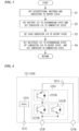
- Fig. 3 is a flowchart showing a process of reducing a rush current according to the embodiment.
- the ECU 140 raises a voltage step by step separately a plurality of times as follows when supply of power to the PDU 130 starts. For example, an example in which the number of times is two will be described below.
- the ECU 140 sets the bidirectional switches 1213 and 1223 in the battery 120 and the contactors 115 and 116 to the cutoff state (S1) and stops charging or discharging the battery 120.
- This process may be performed in a step in which the electric motor 135 is stopped or a step in which the charging or discharging of the battery 120 is first stopped.
- the ECU 140 sets the battery 121 to a discharging state and sets the contactor 116 to the conductive state to start first charging of the capacitor 133, with the contactor 115 being in the cutoff state (S2).
- a PDU power supply side terminal that is, the capacitor 133, is charged with 48 V.
- the ECU 140 sets each contactor to the cutoff state temporarily to avoid short-circuit or the like (S3).
- the ECU 140 maintains the cutoff state of the contactor 116 and sets the contactor 115 to the conductive state to start second charging before the voltage of the capacitor 133 considerably decreases (S4).
- the PDU power side terminal that is, the capacitor 133, is charged with 96 V
- the ECU 140 can separately raise a voltage applied to the PDU 130 step by step twice when the supply of the power to the PDU 130 is started.
- the electric circuit 110 switches connection among the batteries 120 including the batteries 121 and 122, the PDU 130 which is a load of the batteries 120, and the charger 150 supplying power to each of the batteries 120 connected in parallel.
- the diode 111 in the electric circuit 110 rectifies a current to flow the current in a direction oriented from the high-potential side terminal 150P of the charger 150 to the high-potential side terminal 121P of the battery 121.
- the diode 112 rectifies a current to flow the current in a direction oriented from the high-potential side terminal 150P of the charger 150 to the high-potential side terminal 122P of the battery 122.
- the state of the contactors 115 and 116 is switched to connect the batteries 121 and 122 in series between the first pole terminal of the battery 121 and each of the first pole terminal and the second pole terminal of the battery 122 and release the series connection of the batteries 121 and 122 during a period in which the charger 150 supplies the power to the batteries 120.
- the diodes 111 and 112 corresponding to the batteries 121 and 122 are provided, and thus the electric circuit 110 limits short-circuiting of the batteries 120 when the batteries 120 are connected in series.
- the electric circuit 110 can be configured more simply, and the power stored in the batteries 121 and 122 can be used.
- the electric circuit 110 can reduce the number of mechanical switches which can switch between parallel connection at the time of charging and to series connection at the time of discharging, compared to the above-described comparison example.
- the mechanical switches contact points are welded, which is a cause of failures.
- the number of mechanical switches is reduced using the diodes according to the embodiment, it is possible to reduce an occurrence probability of failures.
- the diodes 111 and 112 are connected in mutually reverse directions, thereby preventing short-circuiting.
- the batteries 120 may not be included in the electric circuit 110.
- a battery appropriate for the electric circuit 110 may be combined with the electric circuit 110.
- the polarity of the high-potential side terminal 150P (first pole terminal) of the charger 150 is positive.
- the diode 111 causes a current to flow in a direction oriented from the high-potential side terminal 150P of the charger 150 to the high-potential side terminal 121P of the battery 121.
- the diode 112 causes a current to flow in a direction oriented from the high-potential side terminal 150P of the charger 150 to the high-potential side terminal 122P of the battery 122.
- a negative side in the electric circuit 110 can be configured to be at a common potential.
- Both ends of the battery 120 are connected to the PDU 130.
- the batteries 120 in which the batteries 121 and 122 are connected in series can supply power to the PDU 130 through switching of the state of the contactors 115 and 116.
- the contactors 115 and 116 connect the batteries 120 to the charger 150, the series connection of the batteries 120 is released and the batteries 120 are connected to the charger 150 in parallel with each other.
- two contactors, the contactors 115 and 116, are used so that the series connection and the parallel connection of the batteries 121 and 122 can be switched.
- the contactor 115 switches between connection and non-connection between the low-potential side terminal of the battery 121 and the high-potential side terminal 121P of the battery 122.
- the contactor 116 switches between connection and non-connection between the low-potential side terminal of the battery 121 and the low-potential side terminal 121P of the battery 122.
- the contact 115 can connect the batteries 121 and 122 in series and the contactor 116 can connect them in parallel.
- the batteries 121 and 122 can supply the power to the PDU 130 when the contactor 115 is in the conductive state and the contactor 116 is in the cutoff state.
- the ECU 140 switches between a first connection mode in which the batteries 121 and 122 are connected in parallel and a second connection mode in which the batteries 121 and 122 are connected in series and the capacitor 133 is connected in parallel to both ends of the pair of batteries connected in series.
- the batteries 121 and 122 can be charged in the first connection mode and power can be discharged from the batteries 121 and 122 in the second connection mode.
- the electric circuit 110 can supply charges from the batteries 121 and 122 to the capacitor 133.
- the contactor 116 can electrically connect the battery 121 to the capacitor 133 in parallel.
- the ECU 140 switches among the first connection mode, the second connection mode, and a third connection mode in which the battery 121 and the capacitor 133 are electrically connected in parallel.
- the capacitor 133 can be charged step by step and a rush current at the time of start of charging can be reduced.
- the ECU 140 controls the contactor 115 to the cutoff state and controls the contactor 116 to the conductive state in the first connection mode.
- the ECU 140 controls the contactor 115 to the conductive state and controls the contactor 116 to the cutoff state in the second connection mode.
- the ECU 140 can control the conductive state of the contactors 115 and 116 to switch between charging to the batteries 120 and discharging from the batteries 120.
- the battery 121, the battery 122, and the PDU 130 are provided in the electric motorcycle 1 common to each other and are supplied with electricity by the charger 150 provided outside of the electric motorcycle 1.
- the electric circuit 110 includes a power supply connection terminal unit to which the detachably mounted charger 150 is connected. By releasing connection with the charger 150 via a connection portion with the charger 150 in the power supply connection terminal unit, it is possible to separate the charger 150 from the electric motorcycle 1.
- a battery accommodation unit that accommodates the batteries 121 and 122 is provided in the electric motorcycle 1.
- the batteries 121 and 122 are accommodated in the battery accommodation unit to be easily detachably mounted.
- the batteries 121 and 122 can be easily detachably mounted.
- the conductor 171 electrically connects the high-potential side terminal 121P of the battery 121 to the high-potential side terminal 150P of the charger 150 via the diode 111.
- the branch point P1 is provided in the conductor 171.
- the conductor 172 electrically connects the branch point P1 to the high-potential side terminal 122P of the battery 122 via the diode 112.
- the diodes 111 and 112 can rectify a current in a direction oriented from the branch point P1 to the batteries 121 and 122.
- the branch point P2 is provided in the conductor 172 to be closer to the high-potential side terminal 122P of the battery 122 than the diode 112, and the conductor 173 electrically connects the branch point P2 to the low-potential side terminal 121N of the battery 121.
- the branch point P3 is provided in the conductor 173.
- the conductor 174 electrically connects the branch point P3 to the low-potential side terminal 150N of the charger 150.
- the contactor 115 is interposed to be closer to the branch point P2 than the branch point P3 in the conductor 173.
- the contactor 116 is interposed in the conductor 174.
- a second embodiment will be described.
- the example in which a rush current is reduced by switching connection of the batteries 121 and 122 step by step has been described.
- the embodiment relates to an example in which a rush current is further reduced when the PDU 130 is charged and a state of the electric circuit 110 is diagnosed.
- the control system 10 that controls travel of the electric motorcycle 1 includes the electric circuit 110, the batteries 120, the PDU 130, the ECU 140 and the charger 150.
- the batteries 120 include, for example, the batteries 121 and 122 as in the first embodiment.
- Fig. 4 is a diagram for describing an example of a battery 121 according to the embodiment.
- the battery 121 according to the embodiment includes a battery body 1211, a BMU 1212, and a bidirectional switch 1213 (first bidirectional switch).
- the battery 122 according to the embodiment has a similar configuration as the battery 121. That is, the battery 122 includes a battery body 1221, a BMU 1222, and a bidirectional switch 1223 (second bidirectional switch).
- the bidirectional switch 1213 includes a switch 1213C, a switch 1213D, and a switch 1213P.
- the switch 1213C includes a semiconductor switch and a diode that causes a current to flow in a direction reverse to the direction of a current flowing in the semiconductor switch.
- the switch 1213C is controlled to a conductive state when the battery body 1211 is charged and causes a current to flow from the outside of the battery 121 to the battery body 1211.
- the switch 1213D includes a semiconductor switch and a diode that causes a current to flow in a direction reverse to the direction of a current flowing in the semiconductor switch.
- the switch 1213D is controlled to a conductive state when the battery body 1211 is discharged and causes a current to flow from the battery body 1211 to the outside of the battery 121.
- the switch 1213P includes a semiconductor switch and a diode that causes a current to flow in a direction reverse to the direction of a current flowing in the semiconductor switch.
- the switch 1213P is controlled to a conductive state when the capacitor 133 or the like of the PDU 130 is charged in advance (precharged) by discharging from the battery body 1211 so that a current oriented to the outside of the battery 121 from the battery body 1211 flows.
- the switch 1213P is connected in parallel to the switch 1213D.
- the current caused to flow by the switch 1213P is adjusted to be less than the current caused to flow by the switch 1213D, and thus a rush current at the time of charging of the capacitor 133 of the PDU 130 can be limited.
- the bidirectional switch 1213 cuts a charging or discharging current of the battery 121.
- the bidirectional switch 1223 cuts a charging or discharging current of the battery 122.
- the ECU 140 performs a process of reducing a rush current at the time of initiation or the like and a process of detecting a failure in parallel among a series of processes. The details of each process will be described below.
- the capacitor 133 is provided between terminals on a power supply input side in some cases.
- charging starts from 0 V of a voltage between the terminals of the capacitor 133. Therefore, it is necessary to suppress a rush current.
- the ECU 140 controls the bidirectional switches of the batteries 121 and 122 and external contactors before the supply of power from the batteries 121 and 122 to the PDU 130, thereby reducing the rush current.
- the voltage is configured to be gradually raised separately a plurality of times as follows.
- the number of times the voltage is raised is set to two and a charging current is further adjusted to reduce the rush current will be described.
- a switch state of each unit included in the electric circuit 110 is diagnosed.
- the ECU 140 controls conductive states of the bidirectional switch of each battery and the contactors 115 and 116 at the time of initiation of a vehicle and diagnoses whether there is a failure in each semiconductor switch of the foregoing bidirectional switches and each contactor, the contactors 115 and 116.
- the bidirectional switches of the batteries according to the embodiment are the bidirectional switch 1213 in the battery 121 and the bidirectional switch 1223 in the battery 122.
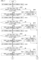
- Figs. 5 and 6 are flowcharts showing a procedure of a process at the time of driving start in the electric circuit according to the embodiment.
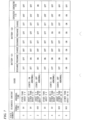
- Fig. 7 is a diagram for describing details of the diagnosis process by the ECU 140 according to the embodiment. In a list showed in Fig. 7 , the diagnosis process is divided into a plurality of states, diagnosis content at the time of stepwise diagnosis, causes assumed from abnormal states, and control content for the batteries 121 and 122 and the contactors 115 and 116 are summarized to correspond to diagnosis process states (state numbers).
- the ECU 140 charges the capacitor 133 in the PDU 130 by switching each state from the following State 0 to State 6 in order and performs the foregoing diagnosis by detecting a voltage storage in the capacitor 133 or the like (hereinafter referred to as a PDU power supply side terminal voltage).
- the ECU 140 sets a diagnosis condition of Diagnosis Item 0 (SA01) and first performs diagnosis of Diagnosis Item 0 immediately after an initiation operation is detected.
- the ECU 140 determines whether the PDU power supply side terminal voltage is within a desired voltage range, with the contactors 115 and 116 and the bidirectional switches 1213 and 1223 in the battery 120 being in the cutoff state (OFF) (SA02).
- An expected value of the PDU power supply side terminal voltage in State 0 is 0 V (volts).
- the ECU 140 determines that there is no abnormality in the result of the diagnosis when the PDU power supply side terminal voltage is within the desired voltage range (for example, about 0 V) (SA03), and determines that there is abnormality in other cases (SA04).
- the ECU 140 causes the control state from State 0 to transition State 1 and sets the diagnosis condition of Diagnosis Item 1 (SA11) and performs diagnosis of Diagnosis Item 1.
- the ECU 140 sets the switch 1213P in the battery 121 to the conductive state (ON) and determines whether the PDU power supply side terminal voltage is within the desired voltage range, with each switch and each contactor excluding the switch 1213P being in the cutoff state (OFF) (SA11).
- An expected value of the PDU power supply side terminal voltage in State 1 is 0 V
- the ECU 140 determines that there is no abnormality in the result of the diagnosis (SA12) when the PDU power supply side terminal voltage is within the desired voltage range (for example, about 0 V), and determines that there is abnormality in other cases (SA13). For example, when a failure occurs with the contact point of the contactor 116 being in the conductive state due to a cause of welding of the contact point of the contactor 116 (ON failure of the contactor 116), the PDU power supply side terminal voltage is detected as a voltage of 48 V or the like.
- the ECU 140 causes the control state from State 1 to transition State 2, sets the diagnosis condition of Diagnosis Item 2 (SA21), and performs diagnosis of Diagnosis Item 2.
- the ECU 140 maintains the conductive state of the switch 1213P in the battery 121, sets the contactor 116 to the conductive state (ON), and determines whether the PDU power supply side terminal voltage is within the desired voltage range, with each switch and each contactor excluding the contactor and the switch being in the cutoff state (SA22).
- An expected value of the PDU power supply side terminal voltage in State 2 is 48 V
- the ECU 140 determines that there is no abnormality in the result of the diagnosis (SA23) when the PDU power supply side terminal voltage is mostly 48 V (for example, about 48 V), and determines that there is abnormality in other cases (SA24).
- 48 V is a voltage value in a state in which the battery 121 is normally charged and is a voltage in a case in which the voltage value is within an allowable variation range.
- the PDU power supply side terminal voltage is detected as a voltage of 0 V or the like.
- the ECU 140 causes the control state from State 2 to transition State 3, sets the diagnosis condition of Diagnosis Item 3 (SA31), and performs diagnosis of Diagnosis Item 3.
- the ECU 140 returns the contactor 116 to the cutoff state and determines whether the PDU power supply side terminal voltage is within the desired voltage range, with each of the other switches and contactors including the switch 1213P in the battery 121 being in the cutoff state (SA32).
- the expected value and the diagnosis content in this state are the same as those in State 1. That is, the ECU 140 determines that there is no abnormality in the result of the diagnosis (SA33) when the PDU power supply side terminal voltage is 0 V, and determines that there is abnormality in other cases (SA34). For example, when welding of the contact point of the contact 115 occurs, the contactor 116 does not return to the cutoff state. Therefore, the PDU power supply side terminal voltage is not mostly 0 V and it is determined that there is abnormality.
- the ECU 140 causes the control state from State 3 to transition State 4, and sets the diagnosis condition of Diagnosis Item 4 (SA41), and performs diagnosis of Diagnosis Item 4.
- SA41 diagnosis condition of Diagnosis Item 4
- the ECU 140 maintains the switch 1213P in the battery 121 in the conductive state, further sets the switch in the battery 122 to the conductive state, and determines whether the PDU power supply side terminal voltage is within the desired voltage range, with each switch and each contactor excluding the switch 1213P being in the cutoff state (SA42).
- An expected value of the PDU power supply side terminal voltage in State 4 is 0 V
- the ECU 140 determines that there is no abnormality in the result of the diagnosis (SA43) when the PDU power supply side terminal voltage is 0 V, and determines that there is abnormality in other cases (SA44). For example, when a failure occurs with the contact point of the contactor 115 being in the conductive state due to a cause of welding of the contact point of the contactor 115 (ON failure of the contactor 115), the PDU power supply side terminal voltage is detected as a voltage of 96 V or the like.
- the ECU 140 causes the control state from State 4 to transition State 5, sets the diagnosis condition of Diagnosis Item 5 (SA51), and performs diagnosis of Diagnosis Item 5.
- the ECU 140 maintains the conductive state of the contactor 116 and the switch 1213P in the battery 121, further sets the switch 1213P in the battery 122 to the conductive state, and determines whether the PDU power supply side terminal voltage is within the desired voltage range, with each switch and each contactor excluding the contactor and the switches being in the cutoff state.
- An expected value of the PDU power supply side terminal voltage in State 5 is 96 V.
- the ECU 140 determines that there is no abnormality in the result of the diagnosis when the PDU power supply side terminal voltage is mostly 96 V (about 96 V), and determines that there is abnormality in other cases.
- 96 V is a voltage in a case in which a voltage value in the state in which the batteries 121 and 122 are normally charged is within an allowable variation range. For example, when a failure occurs with the contact point of the contactor 115 being in the cutoff state due to a cause of no operation of the contact point of the contactor 115 (OFF failure of the contactor 115), the PDU power supply side terminal voltage is detected as a voltage of 0 V
- the ECU 140 determines that the control system 10 normally operates including the electric circuit 110 (SA61) and allows charging or discharging of the batteries 121 and 122 to be executable (SA62). That is, the ECU 140 sets each switch, the bidirectional switch 1213 of the battery 121 and the bidirectional switch 1223 of the battery 122, to the conductive state, and then ends the series of processes showed in the drawings.
- the ECU 140 determines that there is abnormality in the diagnosis result of the diagnosis item of any process and performs a predetermined fail-safe process (SA62). After the ECU 140 ends the process, the ECU 140 ends the series of processes showed in the drawings.
- diagnosis items, the control states, the procedure of the diagnosis process, and the like are exemplary and may be modified in accordance with an object without being limited thereto.
- the ECU 140 determines a voltage in the capacitor 133 when the contactor 115 is in the cutoff state and the contactor 116 is in the conductive state (a first diagnosis mode).
- the ECU 140 determines a voltage in the capacitor 133 when the contactor 115 is in the conductive state and the contactor 116 is in the cutoff state after the first diagnosis mode (a second diagnosis mode).
- the ECU 140 can determine whether there is a failure of the contactor 116 from a determination result in the first diagnosis mode and determine whether there is a failure of the contactor 115 from a determination result in the second diagnosis mode.
- Modification Example 1 of the second embodiment will be described.
- the example in which the batteries 121 and 122 include the bidirectional switches has been described.
- the modification example relates to an example in which the electric circuit 110 includes a bidirectional switch.
- Fig. 8 is a block diagram showing a schematic configuration of a control system controlling travel of the electric motorcycle 1 according to the modification example.
- the control system 10 includes the electric circuit 110, the battery 120, the PDU 130, the ECU 140, and the charger 150.
- the electric circuit 110 include the diodes 111 and 112, the contactors 115 and 116, bidirectional switches 191 and 192, the batteries 121 and 122, and conductors 171 to 175 connecting them.
- the bidirectional switches 191 and 192 are equivalent to the above-described bidirectional switches 1213 and 1223.
- the bidirectional switch 191 is provided between the branch point P4 in the conductor 171 and the high-potential side terminal 121P of the battery 121.
- the bidirectional switch 192 is provided between the branch point P2 in the conductor 172 and the high-potential side terminal 122P of the battery 122.
- the battery 121 includes the battery body 1211 and the BMU 1212.
- the battery 122 includes the battery body 1221 and the BMU 1222.
- the BMU 1212 notifies the ECU 140 to be described below of information regarding the state of the battery body 1211.
- the ECU 140 limits charging or discharging of the battery body 1211 or the like by controlling the bidirectional switches 191 and 192 or the like in accordance with the foregoing monitoring results by the BMUs.
- the electric circuit 110 that has the above-described configuration may be used so that the ECU 140 perform similar processes to those of the second embodiment.
- a third embodiment will be described.
- the position of the contactor 115 in the first embodiment is closer to the branch point P2 than the branch point P3 in the conductor 173.
- the position of the contactor 115 according to the embodiment is modified as follows.
- Fig. 9 is a block diagram showing a schematic configuration of a control system controlling travel of the electric motorcycle 1 according to the embodiment.
- the control system 10 includes the electric circuit 110, the batteries 120, the PDU 130, the ECU 140, and the charger 150.
- the electric circuit 110 include the diodes 111 and 112, the contactors 115 and 116, and conductors 171 to 178.
- the contactor 115 switches between connection and non-connection between the low-potential side terminal 121P of the battery 121 and the high-potential side terminal 121P of the battery 122.
- the contactor 115 is provided between the high-potential side terminal 121P of the battery 121 and the high-potential side terminal 122P of the battery 122 and between the low-potential side terminal 121N of the battery 121 and the high-potential side terminal 122P of the battery 122.
- the contactor 115 connects the batteries 120 in series and releases the series connection of the batteries 120.
- the contactor 115 is provided at the following position.
- the conductor 172 electrically connects the branch point P1 to the high-potential side terminal 122P of the battery 122.
- the diode 112 and the contactor 115 are interposed in the conductor 172.
- a cathode of the diode 112 is connected to the high-potential side terminal 122P of the battery 122 and an anode of the diode 112 is connected to the high-potential side terminal 150P of the charger 150 via the branch point P1.
- a branch point P2 (second branch point) is provided between the cathode of the diode 112 and the high-potential side terminal 122P of the battery 122.
- the contactor 115 according to the embodiment is provided between the branch point P2 and the high-potential side terminal 122P of the battery 122.
- the conductor 173 electrically connects the branch point P2 to the low-potential side terminal 121N of the battery 121.
- a branch point P3 (third branch point) is provided in the conductor 173.
- connection other than the foregoing connection is similar to that of the first embodiment.
- the ECU 140 according to the embodiment may perform similar processes as those of the first or second embodiment.
- the contactor 115 can also be configured to be inserted into the conductor 172 to be closer to the battery 122 than the branch point P2.
- the batteries 120 according to the first to third embodiments include two batteries. Instead of this, the batteries 120 according to the embodiment include three batteries. Hereinafter, differences will be mainly described.
- Fig. 10 is a block diagram showing a schematic configuration of a control system controlling travel of the electric motorcycle 1 according to the embodiment that is not claimed.
- the control system 10 includes the electric circuit 110, the batteries 120, the PDU 130 (load), the ECU 140 (control unit), and the charger 150 (power supply).
- the electric circuit 110 include the diodes 111, 112, 113, and 114, the contactors 115, 116, 117, and 118, the conductors 171 to 178, and conductors 182 to 184.
- the batteries 120 include, for example, batteries 121, 122, and 123.
- the batteries 121, 122, and 123 have the same configuration.
- the diode 113 rectifies a current flowing between the branch point P1 and the high-potential side terminal 150P of the charger 150. For example, the diode 113 causes a current to flow in a direction oriented from the high-potential side terminal 150P of the charger 150 to the branch point P1.
- the diode 114 rectifies a current flowing between the high-potential side terminal 150P of the charger 150 and a high-potential side terminal 123P (first pole terminal) of the battery 123 (third storage cell unit).
- the diode 113 causes a current to flow in a direction oriented from the high-potential side terminal 150P of the charger 150 to the high-potential side terminal 123P of the battery 123.
- the currents flowing in the diodes 111, 112, and 114 are different from each other.
- the polarity of each of the high-potential side terminal 150P of the charger 150, the high-potential side terminal 121P of the battery 121, the high-potential side terminal 122P of the battery 122, and the high-potential side terminal 123P of the battery 123 is the same polarity and is, for example, positive polarity in the embodiment.
- the contactor 117 switches between connection and non-connection of the low-potential side terminal 122N of the battery 122 and the high-potential side terminal 123P of the battery 123.
- the contactor 115 is provided between the high-potential side terminal 122P of the battery 122 and the high-potential side terminal 123P of the battery 123, that is, between the low-potential side terminal 122N of the battery 122 and the high-potential side terminal 123P of the battery 123.
- the contactor 117 contributes to the series connection of the batteries 120 in the conductive state and releases the series connection of the batteries 120 in the cutoff state.
- the contactor 118 switches between connection and non-connection of the low-potential side terminal 122N of the battery 122 and the low-potential side terminal 123N of the battery 123.
- the contactor 118 connects the low-potential side terminal 122N of the battery 122 to the low-potential side terminal 123N of the battery 123 in the conductive state.
- a period in which the contactor 118 is in the conductive state includes at least a period in which the charger 150 supplies power to the batteries 120.
- Both ends of the batteries 120 connected in series are connected to the PDU 130.
- the batteries 121, 122, and 123 in the batteries 120 are connected in series or connected in parallel in accordance with switching of the state of the contactors 115, 116, 117, and 118.
- the contactors 115, 116, 117, and 118 and the diodes 111, 112, 113, and 114 are examples of a connection switching device.
- connection configuration showed in Fig. 10 that is not claimed, is exemplary and can be appropriately modified without being limited thereto.
- the electric circuit 110 that has the foregoing configuration is used so that the ECU 140 can perform similar processes as the processes described in the first or second embodiment.
- the batteries 120 include three batteries.
- the ECU 140 performs charging at a charging voltage separately at three stages when the charging of the capacitor 133 starts, and thus it is possible to further reduce a rush current.
- the battery 121 is discharged to charge the capacitor 133.
- the batteries 121 and 122 are connected in series and discharged to charge the capacitor 133.
- the batteries 121, 122, and 123 are connected in series and discharged to charge the capacitor 133.
- the bidirectional switch in each battery and each contactor state may be diagnosed at the stage at which the foregoing capacitor 133 is charged, as in the second embodiment.
- an electric circuit (110) that switches connection among a plurality of storage cell units (120) including a first storage cell unit (121) and a second storage cell unit (122), a load (130) of the plurality of storage cell units, and a power supply (150) supplying power to the plurality of storage cell units.
- the electric circuit includes: a first rectifier (111) configured to rectify a current flowing between a first pole terminal (150P) of the power supply and a first pole terminal (121P) of the first storage cell unit with homopolarity as polarity of the first pole terminal of the power supply; a second rectifier (112) configured to rectify a current being different from the current and flowing between the first pole terminal of the power supply and a first pole terminal (122P) of the second storage cell unit with homopolarity as the polarity of the first pole terminal of the power supply; and a connection switching device (115, 116) configured to connect the plurality of storage cell units in series between the first pole terminal of the first storage cell unit and the first pole terminal of the second storage cell unit and release the series connection of the plurality of storage cell units during a period in which the power supply supplies power to the plurality of storage cell units.
- a first rectifier configured to rectify a current flowing between a first pole terminal (150P) of the power supply and a first pole terminal (121P) of the
- the ECU 140 includes a computer system.
- the ECU 140 may perform the above-described various processes by recording a program for realizing the foregoing processes on a computer-readable recording medium and causing the computer system to read the program recorded on the recording medium to execute the recorded program.
- the "computer system” mentioned here may include an OS or hardware such as a peripheral device.
- the "computer-readable recording medium” refers to a storage device such as a flexible disc, a magneto-optical disc, a ROM, a writable non-volatile memory such as a flash memory, a portable medium such as a CD-ROM, or a hard disk contained in the computer system.
- the "computer-readable recording medium” is assumed to include a memory that retains a program for a certain time, such as a voltage memory (for example, a dynamic random access memory (DRAM)) in a computer system serving as a client or a server when a program is transmitted via a network such as the Internet or a communication circuit such as a telephone circuit.
- the program may be transmitted from a computer system in which the program is stored in a storage device or the like to another computer system through a transmission medium or transmission waves in the transmission medium.
- the "transmission medium” transmitting a program refers to a medium that has a function of transmitting information, such as a network (communication network) such as the Internet or a communication circuit (communication line) such as a telephone circuit.
- the program may realize some of the above-described functions.
- the program may also be a program combined with a program in which the above-described functions are previously recorded on a computer system, a so-called differential file (differential program).
Landscapes
- Engineering & Computer Science (AREA)
- Power Engineering (AREA)
- Mechanical Engineering (AREA)
- Life Sciences & Earth Sciences (AREA)
- Sustainable Development (AREA)
- Sustainable Energy (AREA)
- Transportation (AREA)
- Charge And Discharge Circuits For Batteries Or The Like (AREA)
- Electric Propulsion And Braking For Vehicles (AREA)
Description
- The present invention relates to a an electric circuit and a diagnosis method provided within an electric vehicle.
- Priority is claimed on
Japanese Patent Application No. 2016-256141, filed December 28, 2016 - In recent years, technologies for motorizing driving schemes of electric vehicles have been known (for example, see Patent Literature 1). As described in
Patent Literature 1, it is necessary to efficiently charge a storage cell unit included in a moving object and it is also necessary to efficiently obtain motivity from power stored in the storage cell unit.Patent Literature 1 andPatent Literature 2 discloses an electric circuit that switches connection by a plurality of switches so that storage cell units (a capacitor group) are in parallel at the time of charging and are in series at the time of discharging. -
- [Patent Literature 1]
Japanese Unexamined Patent Application, First Publication No. 2004-282800 - [Patent Literature 2]
EP 1 113 563 A2 - However, in the electric circuit disclosed in
Patent Literature 1, many switches that appropriately switch a plurality of storage cell units are necessary, and thus a complicated configuration is formed. - An aspect of the present invention is achieved in consideration of such circumstances and one object of the present invention is to provide an electric circuit and a diagnosis method capable of using power stored in a plurality of batteries in a simpler configuration.
- To solve the above-described problem and achieve the related object, the solution according to the present set of claims is provided.
- According to the aspects of the present invention, there is provided moving object which includes, a load of a plurality of batteries including a first battery and a second battery, the load being provided with a capacitor; an electric circuit that switches connection among a plurality of batteries including a first battery and a second battery, a load of the plurality of batteries, and a power supply supplying power to the plurality of batteries. The moving object includes: a first rectifier configured to rectify a current flowing between a first pole terminal of the power supply and a first pole terminal of the first battery with homopolarity with the first pole terminal of the power supply; a second rectifier configured to rectify a current being different from the current and flowing between the first pole terminal of the power supply and a first pole terminal of the second battery with homopolarity with the first pole terminal of the power supply; and a connection switching device configured to connect the plurality of batteries in series between the first pole terminal of the first battery and the first pole terminal of the second battery and release the series connection of the plurality of batteries during a period in which the power supply supplies power to the plurality of batteries. It is possible to provide the battery system and the diagnosis method capable of using power stored in the plurality of batteries in a simpler configuration.
-
-
Fig. 1 is a diagram showing an example of a saddle type electric vehicle to which an electric circuit is applied according to a first embodiment. -
Fig. 2 is a block diagram showing a schematic configuration of a control system controlling travel of anelectric motorcycle 1 according to the embodiment. -
Fig. 3 is a flowchart showing a process of reducing a rush current according to the embodiment. -
Fig. 4 is a diagram for describing an example of a battery according to a second embodiment. -
Fig. 5 is a flowchart showing a procedure of a process at the time of driving start in an electric circuit according to the embodiment. -
Fig. 6 is a flowchart showing the procedure of the process at the time of driving start in an electric circuit according to the embodiment. -
Fig. 7 is a diagram for describing details of a diagnosis process by anECU 140 according to the embodiment. -
Fig. 8 is a block diagram showing a schematic configuration of a control system controlling travel of anelectric motorcycle 1 according to a modification example of the second embodiment. -
Fig. 9 is a block diagram showing a schematic configuration of a control system controlling travel of theelectric motorcycle 1 according to a third embodiment. -
Fig. 10 is a block diagram showing a schematic configuration of a control system controlling travel of theelectric motorcycle 1 according to a fourth embodiment that is not claimed. - Hereinafter, embodiments of the present invention will be described with reference to the drawings. It is assumed that the drawings are ascertained in directions of reference signs and right, left, front, and rear directions are directions in which the reference signs are viewed by a driver.
-
Fig. 1 is a diagram showing an example of a saddle type electric vehicle to which an electric circuit according to an embodiment is applied.Fig. 1 shows an example of a scooter saddle type electric vehicle with a low floor (hereinafter referred to as an "electric motorcycle"). Theelectric motorcycle 1 showed inFig. 1 is an example of a moving object. A body frame F of theelectric motorcycle 1 supports afront fork 11 so thatfront fork 11 can be steered. A front wheel WF is shaft-supported at the lower end of thefront fork 11 and asteering handle 16 is connected to an upper portion of thefront fork 11. - A front end portion of a
swing arm 17 is supported to be pivoted in a rear portion of the body frame F. - An
electric motor 135 is provided in a rear end portion of theswing arm 17 and a rear wheel WR is rotatably driven with power output by theelectric motor 135. - A pair of right and
left seat frames 15 are provided to be connected to a rear portion of the body frame F.A boarding seat 21 is supported by theseat frames 15. Abody cover 22 made of a synthetic resin covering the body frame F is fitted in the body frame F. -
Fig. 1 shows a disposition example of some electric components. For example, a battery accommodation unit 120C made of a synthetic resin is provided below theboarding seat 21 and between the pair of right andleft seat frames 15. Abattery 120 is detachably accommodated in the battery accommodation unit 120C. - The
electric motorcycle 1 travels by theelectric motor 135 provided in theswing arm 17 being driven by aPDU 130 with power supplied via anelectric circuit 110 from thebattery 120 and rotational power at the time of driving by theelectric motor 135 being delivered to the rear wheel WR. For example, thebattery 120 according to the embodiment is partitioned into a plurality of battery units such asbatteries electric motorcycle 1 is controlled by an electric control unit (ECU) 140 or the like disposed in a proper place such as the inside of thebody cover 22 or the like. Acharger 150 converts power supplied from the outside and charges thebattery 120 via theelectric circuit 110. Thecharger 150 may be detachably mounted on theelectric motorcycle 1. -
Fig. 2 is a block diagram showing a schematic configuration of a control system controlling travel of theelectric motorcycle 1 according to the embodiment. - A
control system 10 includes anelectric circuit 110, thebattery 120, a PDU 130 (load), the ECU 140 (control unit), and the charger 150 (power supply). - The
electric circuit 110 includes a diode 111 (first rectifier), a diode 112 (second rectifier), a contactor 115 (first contactor), a contactor 116 (second contactor), andconductors 171 to 178. - The
battery 120 includes, for example, thebatteries battery 120 generates a predetermined voltage (for example, a nominal voltage is 48 V) by connecting a plurality of single batteries such as lithium-ion batteries, nickel metal hydride batteries, or lead batteries in series. Power from thebatteries electric motor 135 via theelectric circuit 110, is converted, for example, from a direct current to a three-phase alternating current by thePDU 130, and is subsequently supplied to theelectric motor 135 which is a three-phase AC motor. The PDU 130 is a so-called inverter. - For example, an output voltage of the
batteries DC converter 126 and is supplied to a control system component such as theECU 140. - For example, an allowable input voltage variation range of the DC-
DC converter 126 includes a voltage obtained by connecting thebatteries DC converter 126, a variation range of a voltage of each of thebatteries batteries - For example, an output voltage of the
batteries - Some of the power of a low voltage dropped by the DC-
DC converter 126 is supplied to thebattery 125 or a general electric component such as a lighting component (not showed). - The
batteries charger 150 connected to a power supply of AC 100 V. - The
battery 121 according to the embodiment includes abattery body 1211, a battery managing unit (BMU) 1212, abidirectional switch 1213, a high-potential side terminal 121P (first pole terminal), a low-potential side terminal 121N (second pole terminal), and aconnector 121C. Similarly, thebattery 122 includes abattery body 1221, aBMU 1222, and abidirectional switch 1223. In the following description, theBMU 1212 and theBMU 1222 are collectively referred to as a unit BMU. A charging or discharging situation, a storage amount, a temperature, and the like of thebatteries batteries ECU 140. The BMU limits charging and discharging of thebattery body 1211 and the like by controlling thebidirectional switch 1213 or the like in accordance with a control instruction from theECU 140 to be described below or the foregoing monitoring result. The details of thebidirectional switch 1213 will be described below. TheBMU 1212 communicates theECU 140 via theconnector 121C. TheBMU 1212 of thebattery 121 is supplied with control power via theconnector 121C. Thebattery 122 is also similar thereto. - Information regarding an output request from a throttle (accelerator)
sensor 180 is input to theECU 140 and theECU 140 controls thecontactors battery 120, thePDU 130, and the like based on the input information regarding the output request. For example, theECU 140 can regulate the charging and discharging of thebattery 120 by controlling thebattery 120. TheECU 140 switches supply of the power to thebattery 120 and discharging from thebattery 120 by controlling thecontactors ECU 140 controls driving of theelectric motor 135 when thePDU 130 controls the power supplied to theelectric motor 135. In the block diagram showed inFig. 2 , thecharger 150 is also included in thecontrol system 10 controlling travel of theelectric motorcycle 1. However, thecharger 150 may be configured to be detachably mounted in theelectric motorcycle 1. In this case, thecharger 150 may be provided outside of theelectric motorcycle 1. - The
diode 111 rectifies a current flowing between a high-potential side terminal 150P (first pole terminal) of thecharger 150 and a high-potential side terminal 121P (first pole terminal) of the battery 121 (first storage cell unit). For example, thediode 111 causes a current to flow in a direction oriented from the high-potential side terminal 150P of thecharger 150 to the high-potential side terminal 121P of thebattery 121. - The
diode 112 rectifies a current flowing between the high-potential side terminal 150P of thecharger 150 and a high-potential side terminal 122P (first pole terminal) of the battery 122 (second storage cell unit). For example, thediode 112 causes a current to flow in a direction oriented from the high-potential side terminal 150P of thecharger 150 to the high-potential side terminal 122P of thebattery 122. - The current flowing in the
diode 111 is different from the current flowing in thediode 112. The polarity of each of the high-potential side terminal 150P of thecharger 150, the high-potential side terminal 121P of thebattery 121, and the high-potential side terminal 122P of thebattery 122 is the same polarity and is, for example, positive polarity in the embodiment. - The
diode 111 corresponding to thebattery 121 and thediode 112 corresponding to thebattery 122 are provided to protect each unit from the following events. - The
diodes potential side terminal 121P of thebattery 121 and the high-potential side terminal 122P of thebattery 122 to the high-potential side terminal 150P of thecharger 150. - The
diode 111 is provided to prevent thebattery 121 from being short-circuited when thebatteries 120 are connected in series. - By providing the
diodes conductors potential side terminal 121P of thebattery 121 to the high-potential side terminal 122P of thebattery 122, when one battery is short-circuited and fails, the other battery is prevented from being short-circuited. - The contactor 115 (first contactor) switches between connection and non-connection of the low-
potential side terminal 121N of thebattery 121 and the high-potential side terminal 122P of thebattery 122. For example, thecontactor 115 is provided between the high-potential side terminal 121P of thebattery 121 and the high-potential side terminal 122P of thebattery 122, that is, between the low-potential side terminal 121N of thebattery 121 and the high-potential side terminal 122P of thebattery 122. Thecontactor 115 connects thebatteries 120 in series in a conductive state and releases the series connection of thebatteries 120 in a cutoff state. A period in which thecontactor 115 is in the cutoff state includes at least a period in which thecharger 150 supplies power to thebattery 120. - The contactor 116 (second contactor) switches between connection and non-connection of the low-
potential side terminal 121N of thebattery 121 and the low-potential side terminal 122N of thebattery 122. For example, thecontactor 116 connects the low-potential side terminal 121N of thebattery 121 to the low-potential side terminal 122N of thebattery 122 in the conductive state. A period in which thecontactor 116 is in the conductive state includes at least a period in which thecharger 150 supplies power to thebatteries 120. - Both ends of the
batteries 120 connected in series are connected to thePDU 130. Thebatteries batteries 120 are connected in series or connected in parallel in accordance with switching of the state of thecontactors contactors diodes - Each unit of the driving system of the
electric circuit 110 is electrically connected as follows by conductors (conducting wires) including the conductor 171 (first conductor), the conductor 172 (second conductor), a conductor 173 (third conductor), a conductor 174 (fourth conductor), aconductor 175, aconductor 176, aconductor 177, and aconductor 178. - The
conductor 171 electrically connects the high-potential side terminal 121P of thebattery 121 to the high-potential side terminal 150P of thecharger 150. Thediode 111 is inserted into theconductor 171. For example, a cathode of thediode 111 is connected to the high-potential side terminal 121P of thebattery 121 and an anode of thediode 111 is connected to the high-potential side terminal 150P of thecharger 150. A branch point P1 (first branch point) is provided between the anode of thediode 111 and the high-potential side terminal 150P of thecharger 150. - The
conductor 172 electrically connects the branch point P1 to the high-potential side terminal 122P of thebattery 122. Thediode 112 is inserted into theconductor 172. For example, a cathode of thediode 112 is connected to the high-potential side terminal 122P of thebattery 122 and an anode of thediode 112 is connected to the high-potential side terminal 150P of thecharger 150 via the branch point P1. A branch point P2 (second branch point) is provided between the cathode of thediode 112 and the high-potential side terminal 121P of thebattery 121. - The
conductor 173 electrically connects the branch point P2 to the low-potential side terminal 121N of thebattery 121. A contact point of thecontactor 115 is inserted into theconductor 173. A branch point P3 (third branch point) is provided in theconductor 173. The position of the branch point P3 is between the contactor 115 and the low-potential side terminal 121N of thebattery 121. - The
conductor 174 electrically connects the branch point P3 to the low-potential side terminal 150N of thecharger 150. A contact point of thecontactor 116 is inserted into theconductor 174. - The
conductor 174 electrically connects the low-potential side terminal (122N) of the battery (122) on a lower potential side among the batteries connected in series to the low-potential side terminal 150N of thecharger 150. - A branch point P4 (fourth branch point) is provided between the cathode of the
diode 111 to the high-potential side terminal 121P of thebattery 121. Theconductor 175 electrically connects the branch point P4 to the high-potential side terminal 130P of thePDU 130. Theconductor 176 electrically connects the branch point P4 to the high-potential side terminal 126P of the DC-DC converter 126. Theconductor 177 connects the low-potential side terminal 130N of thePDU 130 to the low-potential side terminal 150N of thecharger 150. Theconductor 178 connects the low-potential side terminal 126N of the DC-DC converter 126 to the low-potential side terminal 150N of thecharger 150. - The
electric circuit 110 may include connection of a monitoring control system indicated by a dotted line inFig. 2 in addition to the connection of the foregoing driving system. Theelectric circuit 110 may include theECU 140. - The
ECU 140 acquires a state of thebattery 120 from the BMU of thebattery 120. TheECU 140 detects a manipulation by a user from thethrottle sensor 180 or the like. TheECU 140 controls thecontactor 115, thecontactor 116, and thePDU 130 based on the collected information. - When the
battery 120 is charged with power from thecharger 150, theECU 140 sets thecontactor 115 to the cutoff state and sets thecontactor 116 to the conductive state. That is, when thebatteries charger 150 is supplied to thebatteries charger 150 can be supplied to thePDU 130 is achieved, but a voltage of the power is the same as a voltage applied between terminals of thebattery 121. - When the
PDU 130 is driven with power stored in thebattery 120, theECU 140 sets thecontacts 115 to the conductive state and sets thecontactor 116 to the cutoff state. That is, when thebatteries batteries PDU 130. In the foregoing case, thediode 111 is reversely biased and a voltage (for example, 96 V) of the high-potential side terminal 121P of thebattery 121 is not applied to the high-potential side terminal 122P of thebattery 122 and the high-potential side terminal 150P of thecharger 150. - As showed in
Fig. 1 described above, in thePDU 130, acapacitor 133 is provided between input terminals of the power supply in some cases. Thecapacitor 133 is in a state in which the power is supplied to thePDU 130 and charged. When the supply of the power to thePDU 130 is stopped, the power is discharged and the voltage between the terminals of thecapacitor 133 becomes 0 V. Therefore, when the supply of the power to thePDU 130 is started, such as at the time of initiation of theelectric motorcycle 1, charging of a voltage between the terminals of thecapacitor 133 starts from 0 V. - In particular, when charging starts in the state in which the
batteries - Accordingly, the
control system 10 according to the embodiment performs a process of reducing a rush current generated at that time before supply of power from thebatteries PDU 130 starts. -
Fig. 3 is a flowchart showing a process of reducing a rush current according to the embodiment. - For example, the
ECU 140 raises a voltage step by step separately a plurality of times as follows when supply of power to thePDU 130 starts. For example, an example in which the number of times is two will be described below. - First, the
ECU 140 sets thebidirectional switches battery 120 and thecontactors battery 120. - This process may be performed in a step in which the
electric motor 135 is stopped or a step in which the charging or discharging of thebattery 120 is first stopped. - Subsequently, the
ECU 140 sets thebattery 121 to a discharging state and sets thecontactor 116 to the conductive state to start first charging of thecapacitor 133, with thecontactor 115 being in the cutoff state (S2). Thus, a PDU power supply side terminal, that is, thecapacitor 133, is charged with 48 V. - Subsequently, the
ECU 140 sets each contactor to the cutoff state temporarily to avoid short-circuit or the like (S3). - Subsequently, the
ECU 140 maintains the cutoff state of thecontactor 116 and sets thecontactor 115 to the conductive state to start second charging before the voltage of thecapacitor 133 considerably decreases (S4). Thus, the PDU power side terminal, that is, thecapacitor 133, is charged with 96 V - As described above, the
ECU 140 can separately raise a voltage applied to thePDU 130 step by step twice when the supply of the power to thePDU 130 is started. - According to the foregoing embodiment, the
electric circuit 110 switches connection among thebatteries 120 including thebatteries PDU 130 which is a load of thebatteries 120, and thecharger 150 supplying power to each of thebatteries 120 connected in parallel. Thediode 111 in theelectric circuit 110 rectifies a current to flow the current in a direction oriented from the high-potential side terminal 150P of thecharger 150 to the high-potential side terminal 121P of thebattery 121. Thediode 112 rectifies a current to flow the current in a direction oriented from the high-potential side terminal 150P of thecharger 150 to the high-potential side terminal 122P of thebattery 122. The state of thecontactors batteries battery 121 and each of the first pole terminal and the second pole terminal of thebattery 122 and release the series connection of thebatteries charger 150 supplies the power to thebatteries 120. - In this way, the
diodes batteries electric circuit 110 limits short-circuiting of thebatteries 120 when thebatteries 120 are connected in series. Thus, theelectric circuit 110 can be configured more simply, and the power stored in thebatteries - Further, the
electric circuit 110 can reduce the number of mechanical switches which can switch between parallel connection at the time of charging and to series connection at the time of discharging, compared to the above-described comparison example. In the mechanical switches, contact points are welded, which is a cause of failures. However, since the number of mechanical switches is reduced using the diodes according to the embodiment, it is possible to reduce an occurrence probability of failures. - In a path connecting the high-
potential side terminal 121P of thebattery 121 to the high-potential side terminal 122P of thebattery 122, thediodes - The
batteries 120 may not be included in theelectric circuit 110. A battery appropriate for theelectric circuit 110 may be combined with theelectric circuit 110. - The polarity of the high-
potential side terminal 150P (first pole terminal) of thecharger 150 is positive. Thediode 111 causes a current to flow in a direction oriented from the high-potential side terminal 150P of thecharger 150 to the high-potential side terminal 121P of thebattery 121. Thediode 112 causes a current to flow in a direction oriented from the high-potential side terminal 150P of thecharger 150 to the high-potential side terminal 122P of thebattery 122. Thus, a negative side in theelectric circuit 110 can be configured to be at a common potential. - Both ends of the
battery 120 are connected to thePDU 130. Thebatteries 120 in which thebatteries PDU 130 through switching of the state of thecontactors - When the
contactors batteries 120 to thecharger 150, the series connection of thebatteries 120 is released and thebatteries 120 are connected to thecharger 150 in parallel with each other. Thus, two contactors, thecontactors batteries - The
contactor 115 switches between connection and non-connection between the low-potential side terminal of thebattery 121 and the high-potential side terminal 121P of thebattery 122. Thecontactor 116 switches between connection and non-connection between the low-potential side terminal of thebattery 121 and the low-potential side terminal 121P of thebattery 122. Thus, thecontact 115 can connect thebatteries contactor 116 can connect them in parallel. - The
batteries PDU 130 when thecontactor 115 is in the conductive state and thecontactor 116 is in the cutoff state. - When the
charger 150 is connected to theelectric circuit 110 and thus thecontactor 115 is in the cutoff state and thecontactor 116 is in the conductive state, power from thecharger 150 is supplied to thebatteries - The
ECU 140 switches between a first connection mode in which thebatteries batteries capacitor 133 is connected in parallel to both ends of the pair of batteries connected in series. Thus, thebatteries batteries - The
electric circuit 110 can supply charges from thebatteries capacitor 133. Thecontactor 116 can electrically connect thebattery 121 to thecapacitor 133 in parallel. TheECU 140 switches among the first connection mode, the second connection mode, and a third connection mode in which thebattery 121 and thecapacitor 133 are electrically connected in parallel. Thus, thecapacitor 133 can be charged step by step and a rush current at the time of start of charging can be reduced. - The
ECU 140 controls thecontactor 115 to the cutoff state and controls thecontactor 116 to the conductive state in the first connection mode. TheECU 140 controls thecontactor 115 to the conductive state and controls thecontactor 116 to the cutoff state in the second connection mode. Thus, theECU 140 can control the conductive state of thecontactors batteries 120 and discharging from thebatteries 120. - The
battery 121, thebattery 122, and thePDU 130 are provided in theelectric motorcycle 1 common to each other and are supplied with electricity by thecharger 150 provided outside of theelectric motorcycle 1. For example, theelectric circuit 110 includes a power supply connection terminal unit to which the detachably mountedcharger 150 is connected. By releasing connection with thecharger 150 via a connection portion with thecharger 150 in the power supply connection terminal unit, it is possible to separate thecharger 150 from theelectric motorcycle 1. - A battery accommodation unit that accommodates the
batteries electric motorcycle 1. Thebatteries batteries - The
conductor 171 electrically connects the high-potential side terminal 121P of thebattery 121 to the high-potential side terminal 150P of thecharger 150 via thediode 111. The branch point P1 is provided in theconductor 171. Theconductor 172 electrically connects the branch point P1 to the high-potential side terminal 122P of thebattery 122 via thediode 112. Thus, thediodes batteries - The branch point P2 is provided in the
conductor 172 to be closer to the high-potential side terminal 122P of thebattery 122 than thediode 112, and theconductor 173 electrically connects the branch point P2 to the low-potential side terminal 121N of thebattery 121. The branch point P3 is provided in theconductor 173. Theconductor 174 electrically connects the branch point P3 to the low-potential side terminal 150N of thecharger 150. Thecontactor 115 is interposed to be closer to the branch point P2 than the branch point P3 in theconductor 173. Thecontactor 116 is interposed in theconductor 174. Thus, the two contactors are used so that thebatteries - A second embodiment will be described. In the first embodiment, the example in which a rush current is reduced by switching connection of the
batteries PDU 130 is charged and a state of theelectric circuit 110 is diagnosed. - As showed in
Fig. 2 described above, thecontrol system 10 that controls travel of theelectric motorcycle 1 according to the embodiment includes theelectric circuit 110, thebatteries 120, thePDU 130, theECU 140 and thecharger 150. Thebatteries 120 include, for example, thebatteries -
Fig. 4 is a diagram for describing an example of abattery 121 according to the embodiment. - The
battery 121 according to the embodiment includes abattery body 1211, aBMU 1212, and a bidirectional switch 1213 (first bidirectional switch). Thebattery 122 according to the embodiment has a similar configuration as thebattery 121. That is, thebattery 122 includes abattery body 1221, aBMU 1222, and a bidirectional switch 1223 (second bidirectional switch). - The
bidirectional switch 1213 according to the embodiment includes a switch 1213C, aswitch 1213D, and aswitch 1213P. - The switch 1213C includes a semiconductor switch and a diode that causes a current to flow in a direction reverse to the direction of a current flowing in the semiconductor switch. The switch 1213C is controlled to a conductive state when the
battery body 1211 is charged and causes a current to flow from the outside of thebattery 121 to thebattery body 1211. - The
switch 1213D includes a semiconductor switch and a diode that causes a current to flow in a direction reverse to the direction of a current flowing in the semiconductor switch. Theswitch 1213D is controlled to a conductive state when thebattery body 1211 is discharged and causes a current to flow from thebattery body 1211 to the outside of thebattery 121. - The
switch 1213P includes a semiconductor switch and a diode that causes a current to flow in a direction reverse to the direction of a current flowing in the semiconductor switch. Theswitch 1213P is controlled to a conductive state when thecapacitor 133 or the like of thePDU 130 is charged in advance (precharged) by discharging from thebattery body 1211 so that a current oriented to the outside of thebattery 121 from thebattery body 1211 flows. For example, theswitch 1213P is connected in parallel to theswitch 1213D. The current caused to flow by theswitch 1213P is adjusted to be less than the current caused to flow by theswitch 1213D, and thus a rush current at the time of charging of thecapacitor 133 of thePDU 130 can be limited. - The
bidirectional switch 1213 cuts a charging or discharging current of thebattery 121. Thebidirectional switch 1223 cuts a charging or discharging current of thebattery 122. - In the embodiment, the
ECU 140 performs a process of reducing a rush current at the time of initiation or the like and a process of detecting a failure in parallel among a series of processes. The details of each process will be described below. - As showed in
Fig. 1 described above, in thePDU 130, thecapacitor 133 is provided between terminals on a power supply input side in some cases. When supply of power to thePDU 130 starts, charging starts from 0 V of a voltage between the terminals of thecapacitor 133. Therefore, it is necessary to suppress a rush current. - Accordingly, in the
electric circuit 110 according to the embodiment, theECU 140 controls the bidirectional switches of thebatteries batteries PDU 130, thereby reducing the rush current. - For example, when the
ECU 140 starts supplying power to thePDU 130, the voltage is configured to be gradually raised separately a plurality of times as follows. For example, an example in which the number of times the voltage is raised is set to two and a charging current is further adjusted to reduce the rush current will be described. - To improve reliability when the
electric circuit 110 according to the embodiment is used, a switch state of each unit included in theelectric circuit 110 is diagnosed. For example, theECU 140 controls conductive states of the bidirectional switch of each battery and thecontactors contactors bidirectional switch 1213 in thebattery 121 and thebidirectional switch 1223 in thebattery 122. -
Figs. 5 and6 are flowcharts showing a procedure of a process at the time of driving start in the electric circuit according to the embodiment.Fig. 7 is a diagram for describing details of the diagnosis process by theECU 140 according to the embodiment. In a list showed inFig. 7 , the diagnosis process is divided into a plurality of states, diagnosis content at the time of stepwise diagnosis, causes assumed from abnormal states, and control content for thebatteries contactors - As showed in
Figs. 5 and6 , theECU 140 charges thecapacitor 133 in thePDU 130 by switching each state from the followingState 0 toState 6 in order and performs the foregoing diagnosis by detecting a voltage storage in thecapacitor 133 or the like (hereinafter referred to as a PDU power supply side terminal voltage). - First, as showed in
Fig. 5 , theECU 140 sets a diagnosis condition of Diagnosis Item 0 (SA01) and first performs diagnosis ofDiagnosis Item 0 immediately after an initiation operation is detected. TheECU 140 determines whether the PDU power supply side terminal voltage is within a desired voltage range, with thecontactors bidirectional switches battery 120 being in the cutoff state (OFF) (SA02). An expected value of the PDU power supply side terminal voltage inState 0 is 0 V (volts). TheECU 140 determines that there is no abnormality in the result of the diagnosis when the PDU power supply side terminal voltage is within the desired voltage range (for example, about 0 V) (SA03), and determines that there is abnormality in other cases (SA04). - Next, the
ECU 140 causes the control state fromState 0 to transitionState 1 and sets the diagnosis condition of Diagnosis Item 1 (SA11) and performs diagnosis ofDiagnosis Item 1. TheECU 140 sets theswitch 1213P in thebattery 121 to the conductive state (ON) and determines whether the PDU power supply side terminal voltage is within the desired voltage range, with each switch and each contactor excluding theswitch 1213P being in the cutoff state (OFF) (SA11). An expected value of the PDU power supply side terminal voltage inState 1 is 0 V TheECU 140 determines that there is no abnormality in the result of the diagnosis (SA12) when the PDU power supply side terminal voltage is within the desired voltage range (for example, about 0 V), and determines that there is abnormality in other cases (SA13). For example, when a failure occurs with the contact point of thecontactor 116 being in the conductive state due to a cause of welding of the contact point of the contactor 116 (ON failure of the contactor 116), the PDU power supply side terminal voltage is detected as a voltage of 48 V or the like. - Next, the
ECU 140 causes the control state fromState 1 to transitionState 2, sets the diagnosis condition of Diagnosis Item 2 (SA21), and performs diagnosis ofDiagnosis Item 2. TheECU 140 maintains the conductive state of theswitch 1213P in thebattery 121, sets thecontactor 116 to the conductive state (ON), and determines whether the PDU power supply side terminal voltage is within the desired voltage range, with each switch and each contactor excluding the contactor and the switch being in the cutoff state (SA22). An expected value of the PDU power supply side terminal voltage inState 2 is 48 V TheECU 140 determines that there is no abnormality in the result of the diagnosis (SA23) when the PDU power supply side terminal voltage is mostly 48 V (for example, about 48 V), and determines that there is abnormality in other cases (SA24). Mostly 48 V is a voltage value in a state in which thebattery 121 is normally charged and is a voltage in a case in which the voltage value is within an allowable variation range. For example, when a failure occurs with the contact point of thecontactor 116 being in the cutoff state due to a cause of no operation of the contact point of the contactor 116 (OFF failure of the contactor 116), the PDU power supply side terminal voltage is detected as a voltage of 0 V or the like. - Next, the
ECU 140 causes the control state fromState 2 to transitionState 3, sets the diagnosis condition of Diagnosis Item 3 (SA31), and performs diagnosis ofDiagnosis Item 3. TheECU 140 returns thecontactor 116 to the cutoff state and determines whether the PDU power supply side terminal voltage is within the desired voltage range, with each of the other switches and contactors including theswitch 1213P in thebattery 121 being in the cutoff state (SA32). The expected value and the diagnosis content in this state are the same as those inState 1. That is, theECU 140 determines that there is no abnormality in the result of the diagnosis (SA33) when the PDU power supply side terminal voltage is 0 V, and determines that there is abnormality in other cases (SA34). For example, when welding of the contact point of thecontact 115 occurs, thecontactor 116 does not return to the cutoff state. Therefore, the PDU power supply side terminal voltage is not mostly 0 V and it is determined that there is abnormality. - Next, as showed in
Fig. 6 , theECU 140 causes the control state fromState 3 to transitionState 4, and sets the diagnosis condition of Diagnosis Item 4 (SA41), and performs diagnosis ofDiagnosis Item 4. TheECU 140 maintains theswitch 1213P in thebattery 121 in the conductive state, further sets the switch in thebattery 122 to the conductive state, and determines whether the PDU power supply side terminal voltage is within the desired voltage range, with each switch and each contactor excluding theswitch 1213P being in the cutoff state (SA42). An expected value of the PDU power supply side terminal voltage inState 4 is 0 V TheECU 140 determines that there is no abnormality in the result of the diagnosis (SA43) when the PDU power supply side terminal voltage is 0 V, and determines that there is abnormality in other cases (SA44). For example, when a failure occurs with the contact point of thecontactor 115 being in the conductive state due to a cause of welding of the contact point of the contactor 115 (ON failure of the contactor 115), the PDU power supply side terminal voltage is detected as a voltage of 96 V or the like. - Next, the
ECU 140 causes the control state fromState 4 to transitionState 5, sets the diagnosis condition of Diagnosis Item 5 (SA51), and performs diagnosis ofDiagnosis Item 5. TheECU 140 maintains the conductive state of thecontactor 116 and theswitch 1213P in thebattery 121, further sets theswitch 1213P in thebattery 122 to the conductive state, and determines whether the PDU power supply side terminal voltage is within the desired voltage range, with each switch and each contactor excluding the contactor and the switches being in the cutoff state. An expected value of the PDU power supply side terminal voltage inState 5 is 96 V. TheECU 140 determines that there is no abnormality in the result of the diagnosis when the PDU power supply side terminal voltage is mostly 96 V (about 96 V), and determines that there is abnormality in other cases. Mostly 96 V is a voltage in a case in which a voltage value in the state in which thebatteries contactor 115 being in the cutoff state due to a cause of no operation of the contact point of the contactor 115 (OFF failure of the contactor 115), the PDU power supply side terminal voltage is detected as a voltage of 0 V - When abnormality is not detected in any of
Diagnosis Item 0 toDiagnosis Item 5 performed in each of the foregoing processes, theECU 140 determines that thecontrol system 10 normally operates including the electric circuit 110 (SA61) and allows charging or discharging of thebatteries ECU 140 sets each switch, thebidirectional switch 1213 of thebattery 121 and thebidirectional switch 1223 of thebattery 122, to the conductive state, and then ends the series of processes showed in the drawings. - After any process ends among SA04, SA14, SA24, SA34, SA44, and SA54, the
ECU 140 determines that there is abnormality in the diagnosis result of the diagnosis item of any process and performs a predetermined fail-safe process (SA62). After theECU 140 ends the process, theECU 140 ends the series of processes showed in the drawings. - The diagnosis items, the control states, the procedure of the diagnosis process, and the like are exemplary and may be modified in accordance with an object without being limited thereto.
- According to the embodiment, similar advantageous effects to those of the first embodiment can be obtained and the following diagnosis can also be performed. For example, the
ECU 140 determines a voltage in thecapacitor 133 when thecontactor 115 is in the cutoff state and thecontactor 116 is in the conductive state (a first diagnosis mode). TheECU 140 determines a voltage in thecapacitor 133 when thecontactor 115 is in the conductive state and thecontactor 116 is in the cutoff state after the first diagnosis mode (a second diagnosis mode). Thus, it is possible to diagnose the state of theelectric circuit 110 including operational situations of thecontactors capacitor 133. - The
ECU 140 can determine whether there is a failure of the contactor 116 from a determination result in the first diagnosis mode and determine whether there is a failure of the contactor 115 from a determination result in the second diagnosis mode. - Modification Example 1 of the second embodiment will be described. In the second embodiment, the example in which the
batteries electric circuit 110 includes a bidirectional switch. -
Fig. 8 is a block diagram showing a schematic configuration of a control system controlling travel of theelectric motorcycle 1 according to the modification example. - The
control system 10 includes theelectric circuit 110, thebattery 120, thePDU 130, theECU 140, and thecharger 150. - The
electric circuit 110 include thediodes contactors bidirectional switches batteries conductors 171 to 175 connecting them. - The
bidirectional switches bidirectional switches bidirectional switch 191 is provided between the branch point P4 in theconductor 171 and the high-potential side terminal 121P of thebattery 121. Thebidirectional switch 192 is provided between the branch point P2 in theconductor 172 and the high-potential side terminal 122P of thebattery 122. - The
battery 121 according to the embodiment includes thebattery body 1211 and theBMU 1212. - The
battery 122 according to the embodiment includes thebattery body 1221 and theBMU 1222. For example, theBMU 1212 notifies theECU 140 to be described below of information regarding the state of thebattery body 1211. - The
ECU 140 limits charging or discharging of thebattery body 1211 or the like by controlling thebidirectional switches - The
electric circuit 110 that has the above-described configuration may be used so that theECU 140 perform similar processes to those of the second embodiment. - According to the foregoing modification example, similar advantageous effects to those of the second embodiment are obtained even in the example in which the
battery 120 including no bidirectional switch is used. Further, thebidirectional switches ECU 140 and safety in a case in which thebattery 120 including no bidirectional switch is applied can be ensured. - A third embodiment will be described. The position of the
contactor 115 in the first embodiment is closer to the branch point P2 than the branch point P3 in theconductor 173. Instead of this, the position of thecontactor 115 according to the embodiment is modified as follows. -
Fig. 9 is a block diagram showing a schematic configuration of a control system controlling travel of theelectric motorcycle 1 according to the embodiment. - The
control system 10 includes theelectric circuit 110, thebatteries 120, thePDU 130, theECU 140, and thecharger 150. - The
electric circuit 110 include thediodes contactors conductors 171 to 178. - The contactor 115 (first contactor) according to the embodiment switches between connection and non-connection between the low-
potential side terminal 121P of thebattery 121 and the high-potential side terminal 121P of thebattery 122. For example, thecontactor 115 is provided between the high-potential side terminal 121P of thebattery 121 and the high-potential side terminal 122P of thebattery 122 and between the low-potential side terminal 121N of thebattery 121 and the high-potential side terminal 122P of thebattery 122. Thecontactor 115 connects thebatteries 120 in series and releases the series connection of thebatteries 120. - For example, the
contactor 115 is provided at the following position. - The
conductor 172 electrically connects the branch point P1 to the high-potential side terminal 122P of thebattery 122. Thediode 112 and thecontactor 115 are interposed in theconductor 172. For example, a cathode of thediode 112 is connected to the high-potential side terminal 122P of thebattery 122 and an anode of thediode 112 is connected to the high-potential side terminal 150P of thecharger 150 via the branch point P1. A branch point P2 (second branch point) is provided between the cathode of thediode 112 and the high-potential side terminal 122P of thebattery 122. Thecontactor 115 according to the embodiment is provided between the branch point P2 and the high-potential side terminal 122P of thebattery 122. - The
conductor 173 electrically connects the branch point P2 to the low-potential side terminal 121N of thebattery 121. A branch point P3 (third branch point) is provided in theconductor 173. - The connection other than the foregoing connection is similar to that of the first embodiment.
- The
ECU 140 according to the embodiment may perform similar processes as those of the first or second embodiment. - According to the foregoing embodiment, similar advantageous effects to those of the first embodiment can be obtained and the
contactor 115 can also be configured to be inserted into theconductor 172 to be closer to thebattery 122 than the branch point P2. - A fourth embodiment will be described. The
batteries 120 according to the first to third embodiments include two batteries. Instead of this, thebatteries 120 according to the embodiment include three batteries. Hereinafter, differences will be mainly described. -
Fig. 10 is a block diagram showing a schematic configuration of a control system controlling travel of theelectric motorcycle 1 according to the embodiment that is not claimed. - The
control system 10 includes theelectric circuit 110, thebatteries 120, the PDU 130 (load), the ECU 140 (control unit), and the charger 150 (power supply). - The
electric circuit 110 include thediodes contactors conductors 171 to 178, andconductors 182 to 184. - The
batteries 120 include, for example,batteries batteries - The
diode 113 rectifies a current flowing between the branch point P1 and the high-potential side terminal 150P of thecharger 150. For example, thediode 113 causes a current to flow in a direction oriented from the high-potential side terminal 150P of thecharger 150 to the branch point P1. - The
diode 114 rectifies a current flowing between the high-potential side terminal 150P of thecharger 150 and a high-potential side terminal 123P (first pole terminal) of the battery 123 (third storage cell unit). For example, thediode 113 causes a current to flow in a direction oriented from the high-potential side terminal 150P of thecharger 150 to the high-potential side terminal 123P of thebattery 123. - The currents flowing in the
diodes potential side terminal 150P of thecharger 150, the high-potential side terminal 121P of thebattery 121, the high-potential side terminal 122P of thebattery 122, and the high-potential side terminal 123P of thebattery 123 is the same polarity and is, for example, positive polarity in the embodiment. - The contactor 117 (first contactor) switches between connection and non-connection of the low-
potential side terminal 122N of thebattery 122 and the high-potential side terminal 123P of thebattery 123. For example, thecontactor 115 is provided between the high-potential side terminal 122P of thebattery 122 and the high-potential side terminal 123P of thebattery 123, that is, between the low-potential side terminal 122N of thebattery 122 and the high-potential side terminal 123P of thebattery 123. Thecontactor 117 contributes to the series connection of thebatteries 120 in the conductive state and releases the series connection of thebatteries 120 in the cutoff state. - The contactor 118 (second contactor) switches between connection and non-connection of the low-
potential side terminal 122N of thebattery 122 and the low-potential side terminal 123N of thebattery 123. For example, thecontactor 118 connects the low-potential side terminal 122N of thebattery 122 to the low-potential side terminal 123N of thebattery 123 in the conductive state. A period in which thecontactor 118 is in the conductive state includes at least a period in which thecharger 150 supplies power to thebatteries 120. - Both ends of the
batteries 120 connected in series are connected to thePDU 130. Thebatteries batteries 120 are connected in series or connected in parallel in accordance with switching of the state of thecontactors contactors diodes - The connection configuration showed in
Fig. 10 , that is not claimed, is exemplary and can be appropriately modified without being limited thereto. - The
electric circuit 110 that has the foregoing configuration is used so that theECU 140 can perform similar processes as the processes described in the first or second embodiment. - As described above, the
batteries 120 according to the embodiment include three batteries. TheECU 140 performs charging at a charging voltage separately at three stages when the charging of thecapacitor 133 starts, and thus it is possible to further reduce a rush current. - For example, in a first stage, the
battery 121 is discharged to charge thecapacitor 133. In a second stage, thebatteries capacitor 133. In a third stage, thebatteries capacitor 133. - Although detailed description is omitted, the bidirectional switch in each battery and each contactor state may be diagnosed at the stage at which the foregoing
capacitor 133 is charged, as in the second embodiment. - According to the foregoing embodiments, similar advantageous effects as those of the first embodiment can be obtained and application to a case in which three or more batteries are combined to configure the
batteries 120 can also be achieved, and thus theelectric circuit 110 can be configured more simply and at least the power stored in thebatteries - According to at least one of the above-described embodiments, there is provided an electric circuit (110) that switches connection among a plurality of storage cell units (120) including a first storage cell unit (121) and a second storage cell unit (122), a load (130) of the plurality of storage cell units, and a power supply (150) supplying power to the plurality of storage cell units. The electric circuit includes: a first rectifier (111) configured to rectify a current flowing between a first pole terminal (150P) of the power supply and a first pole terminal (121P) of the first storage cell unit with homopolarity as polarity of the first pole terminal of the power supply; a second rectifier (112) configured to rectify a current being different from the current and flowing between the first pole terminal of the power supply and a first pole terminal (122P) of the second storage cell unit with homopolarity as the polarity of the first pole terminal of the power supply; and a connection switching device (115, 116) configured to connect the plurality of storage cell units in series between the first pole terminal of the first storage cell unit and the first pole terminal of the second storage cell unit and release the series connection of the plurality of storage cell units during a period in which the power supply supplies power to the plurality of storage cell units. Thus, the power stored in the plurality of storage cell units can be used with a simpler configuration.
- The
ECU 140 according to the embodiment includes a computer system. TheECU 140 may perform the above-described various processes by recording a program for realizing the foregoing processes on a computer-readable recording medium and causing the computer system to read the program recorded on the recording medium to execute the recorded program. The "computer system" mentioned here may include an OS or hardware such as a peripheral device. The "computer-readable recording medium" refers to a storage device such as a flexible disc, a magneto-optical disc, a ROM, a writable non-volatile memory such as a flash memory, a portable medium such as a CD-ROM, or a hard disk contained in the computer system. - Further, the "computer-readable recording medium" is assumed to include a memory that retains a program for a certain time, such as a voltage memory (for example, a dynamic random access memory (DRAM)) in a computer system serving as a client or a server when a program is transmitted via a network such as the Internet or a communication circuit such as a telephone circuit. The program may be transmitted from a computer system in which the program is stored in a storage device or the like to another computer system through a transmission medium or transmission waves in the transmission medium. Here, the "transmission medium" transmitting a program refers to a medium that has a function of transmitting information, such as a network (communication network) such as the Internet or a communication circuit (communication line) such as a telephone circuit. The program may realize some of the above-described functions. Further, the program may also be a program combined with a program in which the above-described functions are previously recorded on a computer system, a so-called differential file (differential program).
- While preferred embodiments of the invention have been described and showed above, it should be understood that these are exemplary of the invention and are not to be considered as limiting. Additions, omissions, substitutions, and other modifications can be made without departing from scope of the present invention as defined in the appended claims. Accordingly, the invention is not to be considered as being limited by the foregoing description, and is only limited by the scope of the appended claims.
-
- 1 Electric motorcycle (moving object)
- 110 Electric circuit
- 115, 116, 117, 118 Contactor (connection switching device)
- 120, 121, 122, 123 Battery (storage cell unit)
- 120C Battery accommodation unit (accommodation unit)
- 130 PDU (load)
- 133 Capacitor (third storage cell unit)
- 135 Electric motorcycle
- 140 ECU (control unit)
- 150 Charger (power supply)
- 171, 172, 173, 174, 175, 176, 177, 178 Conductor
- 1212, 1222, 1232 BMU
Claims (15)
- An electric vehicle (1) comprising:a load (130) of a plurality of batteries (120) including a first battery (121) and a second battery (122), the load (130) being provided with a capacitor (133);an electric circuit (110) that is configured to switch connection among the plurality of batteries (120), the load (130), and a power supply (150) supplying power to the plurality of batteries (120)a first rectifier (111) configured to rectify a current flowing between a high-potential side terminal (150P) of the power supply (150) and a high-potential side terminal (121P) of the first battery (121);a second rectifier (112) configured to rectify a current being different from the current and flowing between the high-potential side terminal (150P) of the power supply (150) and a high-potential side terminal (122P) of the second battery (122); andconnection switching devices (115-118) configured to connect the plurality of batteries (120) in series and release the series connection of the plurality of batteries (120) during a period in which the power supply (150) supplies power to the plurality of batteries (120),wherein the connection switching devices (115-118) includea first contactor (115) configured to switch connection and non-connection between a low-potential side terminal (121N) of the first battery (121) and the high-potential side terminal (122P) of the second battery (122), anda second contactor (116) configured to switch connection and non-connection between the low-potential side terminal (121N) of the first battery (121) and a low-potential side terminal (122N) of the second battery (122),the electric vehicle (1) further comprising:
a control unit (140) configured to control the connection switching devices to switch among a first connection mode in which the first battery (121), the second battery (122) are connected in parallel, a second connection mode in which a capacitor (133) is connected in parallel to both ends of a pair of the first battery (121) and the second battery (122) connected in series, and a third connection mode in which the first battery (121) and the capacitor (133) are electrically connected in parallel. - The electric vehicle (1) according to claim 1,wherein both ends of a pair of the plurality of batteries (120) connected in series are connected to the load (130), andwherein the connection switching devices (115-118) perform switching to connect the plurality of batteries (120) in series.
- The electric vehicle (1) according to claim 1 or 2, wherein the connection switching devices (115-118) perform switching to release the series connection and connect the plurality of batteries (120) in parallel to the power supply (150).
- The electric vehicle (1) according to claim 1, wherein, when the first contactor (115) is in a conductive state and the second contactor (116) is in a cutoff state, power is supplied from the first battery (121) and the second battery (122) to the load (130).
- The electric vehicle (1) according to claim 1 or 4, wherein, when the first contactor (115) is in the cutoff state and the second contactor (116) is in the conductive state, power is supplied from the power supply (150) to the first battery (121) and the second battery (122).
- The electric vehicle (1) according to claim 1,wherein the control unit (140) controls the first contactor (115) to be in the cutoff state and controls the second contactor (116) to be in the conductive state in the first connection mode, andwherein the control unit (140) controls the first contactor (115) to be in the conductive state and controls the second contactor (116) to be in the cutoff state in the second connection mode.
- The electric vehicle (1) according to any one of claims 1-6, further comprising:a first bidirectional switch (1213) configured to cut a charging or discharging current of the first battery (121); anda second bidirectional switch (1223) configured to cut a charging or discharging current of the second battery (122).
- The electric vehicle (1) according to any one of claims 1-7, wherein the first battery (121) and the second battery (122) are provided in a moving object (1) including the load (130) and are supplied with electricity by a power supply (150) provided outside of the moving object (1).
- The electric vehicle (1) according to claim 8,wherein an accommodation unit (120C) accommodating each of the first battery (121) and the second battery (122) is provided in the moving object (1), andwherein the first battery (121) and the second battery (122) are accommodated in the accommodation unit (120C) to be easily detachably mounted.
- The electric vehicle (1) according to any one of claims 1 and 4-6, further comprising:a first conductor (171) configured to electrically connect the high-potential side terminal (121P) of the first battery (121) to the high-potential side terminal (150P) of the power supply (150) via the first rectifier (111); anda second conductor (172) configured to electrically connect a first branch point (P1) provided in the first conductor (171) to the high-potential side terminal (122P) of the second battery (122) via the second rectifier (112).
- The electric vehicle (1) according to claim 10, further comprising:a third conductor (173) configured to electrically connect a second branch point (P2), provided in the second conductor (172) to be closer to the high-potential side terminal (122P) of the second battery (122) than the second rectifier (112), to the low-potential side terminal (121N) of the first battery (121); anda fourth conductor (174) configured to electrically connect a third branch point (P3), which is provided in the third conductor (173) to a low-potential side terminal (150N) of the power supply (150),wherein the first contactor (115) is interposed to be closer to the second branch point (P2) than the third branch point (P3) in the third conductor (173) or closer to the second battery (122) than the second branch point (P2) of the second conductor (172), andwherein the second contactor (116) is interposed in the fourth conductor (174).
- The electric vehicle (1) according to any one of claims 1-11,
wherein the first rectifier (111) is configured to cause a current to flow in a direction oriented from the high-potential side terminal (150P) of the power supply (150) to the high-potential side terminal (121P) of the first battery (121), and
wherein the second rectifier (112) is configured to cause a current to flow in a direction oriented from the high-potential side terminal (150P) of the power supply (150) to the high-potential side terminal (122P) of the second battery (122). - A diagnosis method for an electric vehicle (1) which includes:
a load (130) of a plurality of batteries (120) including a first battery (121) and a second battery (122), the load (130) being provided with a capacitor (133);an electric circuit (110) that switches connection among the plurality of batteries (120), the load (130), and a power supply (150) supplying power to the plurality of batteries (120);
a first rectifier (111) configured to rectify a current flowing between a high-potential side terminal (150P) of the power supply (150) and a high-potential side terminal (121P) of the first battery (121),a second rectifier (112) configured to rectify a current being different from the current and flowing between the high-potential side terminal (150P) of the power supply (150) and a high-potential side terminal (122P) of the second battery (122); andconnection switching devices (115-118) configured to connect the plurality of batteries (120) in series and release the series connection of the plurality of batteries (120) during a period in which the power supply (150) supplies power to the plurality of batteries (120),wherein the connection switching devices (115-118) includea first contactor (115) configured to switch connection and non-connection between a low-potential side terminal (121N) of the first battery (121) and the high-potential side terminal (122P) of the second battery (122), anda second contactor (116) configured to switch connection and non-connection between the low-potential side terminal (121N) of the first battery (121) and a low-potential side terminal (122N) of the second battery (122), andwherein the diagnosis method comprises:performing a first diagnosis mode in which the first contactor (115) is set to a cutoff state, the second contactor (116) is set to a conductive state, and a voltage of the capacitor (133) is determined; andperforming a second diagnosis mode in which the first contactor (115) is set to the conductive state, the second contactor (116) is set to the cutoff state, and a voltage of the capacitor (133) is determined, after the first diagnosis mode. - The diagnosis method for the electric vehicle (1) according to claim 13, further comprising:
determining presence or absence of a failure of the second contactor (116) from a result of determination in the first diagnosis mode. - The diagnosis method for the electric vehicle (1) according to claim 13 or 14, further comprising:
determining presence or absence of a failure of the first contactor (115) from a result of determination in the second diagnosis mode.
Applications Claiming Priority (2)
| Application Number | Priority Date | Filing Date | Title |
|---|---|---|---|
| JP2016256141 | 2016-12-28 | ||
| PCT/JP2017/042479 WO2018123391A1 (en) | 2016-12-28 | 2017-11-28 | Electric circuit and diagnosis method |
Publications (3)
| Publication Number | Publication Date |
|---|---|
| EP3550695A1 EP3550695A1 (en) | 2019-10-09 |
| EP3550695A4 EP3550695A4 (en) | 2019-12-04 |
| EP3550695B1 true EP3550695B1 (en) | 2024-02-14 |
Family
ID=62708156
Family Applications (1)
| Application Number | Title | Priority Date | Filing Date |
|---|---|---|---|
| EP17889116.4A Active EP3550695B1 (en) | 2016-12-28 | 2017-11-28 | Electric circuit and diagnosis method |
Country Status (5)
| Country | Link |
|---|---|
| US (1) | US11065961B2 (en) |
| EP (1) | EP3550695B1 (en) |
| JP (1) | JP6648310B2 (en) |
| CN (1) | CN110168840B (en) |
| WO (1) | WO2018123391A1 (en) |
Families Citing this family (10)
| Publication number | Priority date | Publication date | Assignee | Title |
|---|---|---|---|---|
| JP6545230B2 (en) * | 2017-08-31 | 2019-07-17 | 本田技研工業株式会社 | Vehicle power system |
| WO2019049338A1 (en) * | 2017-09-08 | 2019-03-14 | 新電元工業株式会社 | Power control device and control method for power control device |
| EP3664251B1 (en) * | 2018-12-07 | 2021-03-03 | Yazaki Corporation | Power supply system |
| JP7237682B2 (en) * | 2019-03-25 | 2023-03-13 | 株式会社Subaru | vehicle power supply |
| JP7034560B2 (en) * | 2019-07-11 | 2022-03-14 | 矢崎総業株式会社 | Power supply |
| US11295557B2 (en) * | 2019-10-23 | 2022-04-05 | Uber Technologies, Inc. | Light electric vehicle defect management based on user profiles |
| JP7342819B2 (en) * | 2020-08-25 | 2023-09-12 | 株式会社デンソー | power system |
| CN114274792A (en) * | 2020-10-01 | 2022-04-05 | 郑州创狼信息技术有限公司 | Direct current power supply system and battery module charging system thereof |
| CN113665715B (en) * | 2021-08-27 | 2025-08-22 | 天津爱玛车业科技有限公司 | Battery interconnection matching device and electric vehicle |
| WO2025196909A1 (en) * | 2024-03-18 | 2025-09-25 | 本田技研工業株式会社 | Electric power supply device and apparatus |
Family Cites Families (11)
| Publication number | Priority date | Publication date | Assignee | Title |
|---|---|---|---|---|
| JPH01248935A (en) * | 1988-03-28 | 1989-10-04 | Toshiba Corp | Battery backup device |
| US6140800A (en) * | 1999-05-27 | 2000-10-31 | Peterson; William Anders | Autonomous battery equalization circuit |
| JP4075260B2 (en) | 1999-12-27 | 2008-04-16 | ソニー株式会社 | Battery pack, power supply device, and charging and discharging method |
| TW564589B (en) * | 2001-11-09 | 2003-12-01 | Tai-He Yang | Random input multi-staged voltage tiny stream electricity storage apparatus |
| JP2004282800A (en) | 2003-03-12 | 2004-10-07 | Nissan Motor Co Ltd | Power supply control device for vehicles |
| JP2007053838A (en) | 2005-08-17 | 2007-03-01 | Toshiba Corp | Power storage device |
| JP5348312B2 (en) * | 2010-02-26 | 2013-11-20 | トヨタ自動車株式会社 | vehicle |
| CN101860050B (en) * | 2010-04-09 | 2012-07-04 | 福州福光电子有限公司 | Discharge test device for distributed full online storage battery pack |
| JP2012005160A (en) * | 2010-06-14 | 2012-01-05 | Hitachi Ltd | Charge/discharge circuit and built-in controller |
| WO2014097407A1 (en) * | 2012-12-18 | 2014-06-26 | ボルボ ラストバグナー アクチエボラグ | Power storage system |
| US9225191B2 (en) * | 2013-02-19 | 2015-12-29 | Freescale Semiconductor, Inc. | Circuit and method for voltage equalization in large batteries |
-
2017
- 2017-11-28 JP JP2018558919A patent/JP6648310B2/en active Active
- 2017-11-28 EP EP17889116.4A patent/EP3550695B1/en active Active
- 2017-11-28 US US16/473,655 patent/US11065961B2/en active Active
- 2017-11-28 WO PCT/JP2017/042479 patent/WO2018123391A1/en not_active Ceased
- 2017-11-28 CN CN201780080804.9A patent/CN110168840B/en active Active
Also Published As
| Publication number | Publication date |
|---|---|
| JP6648310B2 (en) | 2020-02-14 |
| US11065961B2 (en) | 2021-07-20 |
| EP3550695A1 (en) | 2019-10-09 |
| EP3550695A4 (en) | 2019-12-04 |
| JPWO2018123391A1 (en) | 2019-07-11 |
| CN110168840A (en) | 2019-08-23 |
| US20190356139A1 (en) | 2019-11-21 |
| CN110168840B (en) | 2023-04-04 |
| WO2018123391A1 (en) | 2018-07-05 |
Similar Documents
| Publication | Publication Date | Title |
|---|---|---|
| EP3550695B1 (en) | Electric circuit and diagnosis method | |
| US12074433B2 (en) | Electric system and method for energizing the electric system | |
| US20110286137A1 (en) | Traction battery having increased reliability | |
| US11351866B2 (en) | Battery controller for an electrically driven vehicle without any low-voltage battery, electrically driven vehicle comprising said controller, and method | |
| JP5772784B2 (en) | Vehicle, power supply system, and control method for power supply system | |
| US9193272B2 (en) | Jump-starting method and device for implementing the method | |
| EP2879900B1 (en) | Electrical storage system | |
| KR101740824B1 (en) | Power supply apparatus | |
| WO2013042166A1 (en) | Electrical storage system and method for controlling electrical storage system | |
| JPWO2019151231A1 (en) | Power storage device and vehicle equipped with it | |
| JP2013085336A (en) | Power storage system, and control method for power storage system | |
| JP2014180185A (en) | Battery module | |
| US9252608B2 (en) | Electrical storage system, and control method for electrical storage system | |
| JP6600974B2 (en) | Battery control device | |
| CN117996688A (en) | Active short circuit control method and device | |
| CN110234531B (en) | Control system, mobile body, and control method | |
| US12160126B2 (en) | In-vehicle battery system | |
| JP2021087280A (en) | Battery control device | |
| JP5658936B2 (en) | Secondary battery pack, charger and vehicle | |
| JP2017216796A (en) | Electric vehicle | |
| JP6668210B2 (en) | Power supply control device and power supply system | |
| JP7168913B2 (en) | vehicle power system | |
| JP2010041817A (en) | Power supply unit for vehicle | |
| JP2014223004A (en) | Power storage system |
Legal Events
| Date | Code | Title | Description |
|---|---|---|---|
| STAA | Information on the status of an ep patent application or granted ep patent |
Free format text: STATUS: THE INTERNATIONAL PUBLICATION HAS BEEN MADE |
|
| PUAI | Public reference made under article 153(3) epc to a published international application that has entered the european phase |
Free format text: ORIGINAL CODE: 0009012 |
|
| STAA | Information on the status of an ep patent application or granted ep patent |
Free format text: STATUS: REQUEST FOR EXAMINATION WAS MADE |
|
| 17P | Request for examination filed |
Effective date: 20190704 |
|
| AK | Designated contracting states |
Kind code of ref document: A1 Designated state(s): AL AT BE BG CH CY CZ DE DK EE ES FI FR GB GR HR HU IE IS IT LI LT LU LV MC MK MT NL NO PL PT RO RS SE SI SK SM TR |
|
| AX | Request for extension of the european patent |
Extension state: BA ME |
|
| A4 | Supplementary search report drawn up and despatched |
Effective date: 20191107 |
|
| RIC1 | Information provided on ipc code assigned before grant |
Ipc: B60L 58/19 20190101ALI20191031BHEP Ipc: B60L 3/00 20190101ALI20191031BHEP Ipc: H02J 7/00 20060101AFI20191031BHEP |
|
| DAV | Request for validation of the european patent (deleted) | ||
| DAX | Request for extension of the european patent (deleted) | ||
| STAA | Information on the status of an ep patent application or granted ep patent |
Free format text: STATUS: EXAMINATION IS IN PROGRESS |
|
| 17Q | First examination report despatched |
Effective date: 20210507 |
|
| GRAP | Despatch of communication of intention to grant a patent |
Free format text: ORIGINAL CODE: EPIDOSNIGR1 |
|
| STAA | Information on the status of an ep patent application or granted ep patent |
Free format text: STATUS: GRANT OF PATENT IS INTENDED |
|
| INTG | Intention to grant announced |
Effective date: 20230127 |
|
| GRAJ | Information related to disapproval of communication of intention to grant by the applicant or resumption of examination proceedings by the epo deleted |
Free format text: ORIGINAL CODE: EPIDOSDIGR1 |
|
| STAA | Information on the status of an ep patent application or granted ep patent |
Free format text: STATUS: EXAMINATION IS IN PROGRESS |
|
| INTC | Intention to grant announced (deleted) | ||
| GRAS | Grant fee paid |
Free format text: ORIGINAL CODE: EPIDOSNIGR3 |
|
| STAA | Information on the status of an ep patent application or granted ep patent |
Free format text: STATUS: GRANT OF PATENT IS INTENDED |
|
| GRAP | Despatch of communication of intention to grant a patent |
Free format text: ORIGINAL CODE: EPIDOSNIGR1 |
|
| INTG | Intention to grant announced |
Effective date: 20231009 |
|
| GRAA | (expected) grant |
Free format text: ORIGINAL CODE: 0009210 |
|
| STAA | Information on the status of an ep patent application or granted ep patent |
Free format text: STATUS: THE PATENT HAS BEEN GRANTED |
|
| P01 | Opt-out of the competence of the unified patent court (upc) registered |
Effective date: 20240103 |
|
| AK | Designated contracting states |
Kind code of ref document: B1 Designated state(s): AL AT BE BG CH CY CZ DE DK EE ES FI FR GB GR HR HU IE IS IT LI LT LU LV MC MK MT NL NO PL PT RO RS SE SI SK SM TR |
|
| REG | Reference to a national code |
Ref country code: GB Ref legal event code: FG4D |
|
| REG | Reference to a national code |
Ref country code: CH Ref legal event code: EP |
|
| REG | Reference to a national code |
Ref country code: DE Ref legal event code: R096 Ref document number: 602017079244 Country of ref document: DE |
|
| REG | Reference to a national code |
Ref country code: IE Ref legal event code: FG4D |
|
| REG | Reference to a national code |
Ref country code: LT Ref legal event code: MG9D |
|
| REG | Reference to a national code |
Ref country code: NL Ref legal event code: MP Effective date: 20240214 |
|
| PG25 | Lapsed in a contracting state [announced via postgrant information from national office to epo] |
Ref country code: IS Free format text: LAPSE BECAUSE OF FAILURE TO SUBMIT A TRANSLATION OF THE DESCRIPTION OR TO PAY THE FEE WITHIN THE PRESCRIBED TIME-LIMIT Effective date: 20240614 |
|
| PG25 | Lapsed in a contracting state [announced via postgrant information from national office to epo] |
Ref country code: LT Free format text: LAPSE BECAUSE OF FAILURE TO SUBMIT A TRANSLATION OF THE DESCRIPTION OR TO PAY THE FEE WITHIN THE PRESCRIBED TIME-LIMIT Effective date: 20240214 |
|
| PG25 | Lapsed in a contracting state [announced via postgrant information from national office to epo] |
Ref country code: GR Free format text: LAPSE BECAUSE OF FAILURE TO SUBMIT A TRANSLATION OF THE DESCRIPTION OR TO PAY THE FEE WITHIN THE PRESCRIBED TIME-LIMIT Effective date: 20240515 |
|
| REG | Reference to a national code |
Ref country code: AT Ref legal event code: MK05 Ref document number: 1657895 Country of ref document: AT Kind code of ref document: T Effective date: 20240214 |
|
| PG25 | Lapsed in a contracting state [announced via postgrant information from national office to epo] |
Ref country code: RS Free format text: LAPSE BECAUSE OF FAILURE TO SUBMIT A TRANSLATION OF THE DESCRIPTION OR TO PAY THE FEE WITHIN THE PRESCRIBED TIME-LIMIT Effective date: 20240514 Ref country code: HR Free format text: LAPSE BECAUSE OF FAILURE TO SUBMIT A TRANSLATION OF THE DESCRIPTION OR TO PAY THE FEE WITHIN THE PRESCRIBED TIME-LIMIT Effective date: 20240214 Ref country code: NL Free format text: LAPSE BECAUSE OF FAILURE TO SUBMIT A TRANSLATION OF THE DESCRIPTION OR TO PAY THE FEE WITHIN THE PRESCRIBED TIME-LIMIT Effective date: 20240214 |
|
| PG25 | Lapsed in a contracting state [announced via postgrant information from national office to epo] |
Ref country code: ES Free format text: LAPSE BECAUSE OF FAILURE TO SUBMIT A TRANSLATION OF THE DESCRIPTION OR TO PAY THE FEE WITHIN THE PRESCRIBED TIME-LIMIT Effective date: 20240214 |
|
| PG25 | Lapsed in a contracting state [announced via postgrant information from national office to epo] |
Ref country code: AT Free format text: LAPSE BECAUSE OF FAILURE TO SUBMIT A TRANSLATION OF THE DESCRIPTION OR TO PAY THE FEE WITHIN THE PRESCRIBED TIME-LIMIT Effective date: 20240214 |
|
| PG25 | Lapsed in a contracting state [announced via postgrant information from national office to epo] |
Ref country code: RS Free format text: LAPSE BECAUSE OF FAILURE TO SUBMIT A TRANSLATION OF THE DESCRIPTION OR TO PAY THE FEE WITHIN THE PRESCRIBED TIME-LIMIT Effective date: 20240514 Ref country code: NO Free format text: LAPSE BECAUSE OF FAILURE TO SUBMIT A TRANSLATION OF THE DESCRIPTION OR TO PAY THE FEE WITHIN THE PRESCRIBED TIME-LIMIT Effective date: 20240514 Ref country code: NL Free format text: LAPSE BECAUSE OF FAILURE TO SUBMIT A TRANSLATION OF THE DESCRIPTION OR TO PAY THE FEE WITHIN THE PRESCRIBED TIME-LIMIT Effective date: 20240214 Ref country code: LT Free format text: LAPSE BECAUSE OF FAILURE TO SUBMIT A TRANSLATION OF THE DESCRIPTION OR TO PAY THE FEE WITHIN THE PRESCRIBED TIME-LIMIT Effective date: 20240214 Ref country code: IS Free format text: LAPSE BECAUSE OF FAILURE TO SUBMIT A TRANSLATION OF THE DESCRIPTION OR TO PAY THE FEE WITHIN THE PRESCRIBED TIME-LIMIT Effective date: 20240614 Ref country code: HR Free format text: LAPSE BECAUSE OF FAILURE TO SUBMIT A TRANSLATION OF THE DESCRIPTION OR TO PAY THE FEE WITHIN THE PRESCRIBED TIME-LIMIT Effective date: 20240214 Ref country code: GR Free format text: LAPSE BECAUSE OF FAILURE TO SUBMIT A TRANSLATION OF THE DESCRIPTION OR TO PAY THE FEE WITHIN THE PRESCRIBED TIME-LIMIT Effective date: 20240515 Ref country code: FI Free format text: LAPSE BECAUSE OF FAILURE TO SUBMIT A TRANSLATION OF THE DESCRIPTION OR TO PAY THE FEE WITHIN THE PRESCRIBED TIME-LIMIT Effective date: 20240214 Ref country code: ES Free format text: LAPSE BECAUSE OF FAILURE TO SUBMIT A TRANSLATION OF THE DESCRIPTION OR TO PAY THE FEE WITHIN THE PRESCRIBED TIME-LIMIT Effective date: 20240214 Ref country code: BG Free format text: LAPSE BECAUSE OF FAILURE TO SUBMIT A TRANSLATION OF THE DESCRIPTION OR TO PAY THE FEE WITHIN THE PRESCRIBED TIME-LIMIT Effective date: 20240214 Ref country code: AT Free format text: LAPSE BECAUSE OF FAILURE TO SUBMIT A TRANSLATION OF THE DESCRIPTION OR TO PAY THE FEE WITHIN THE PRESCRIBED TIME-LIMIT Effective date: 20240214 |
|
| PG25 | Lapsed in a contracting state [announced via postgrant information from national office to epo] |
Ref country code: PT Free format text: LAPSE BECAUSE OF FAILURE TO SUBMIT A TRANSLATION OF THE DESCRIPTION OR TO PAY THE FEE WITHIN THE PRESCRIBED TIME-LIMIT Effective date: 20240614 Ref country code: PL Free format text: LAPSE BECAUSE OF FAILURE TO SUBMIT A TRANSLATION OF THE DESCRIPTION OR TO PAY THE FEE WITHIN THE PRESCRIBED TIME-LIMIT Effective date: 20240214 |
|
| PG25 | Lapsed in a contracting state [announced via postgrant information from national office to epo] |
Ref country code: SE Free format text: LAPSE BECAUSE OF FAILURE TO SUBMIT A TRANSLATION OF THE DESCRIPTION OR TO PAY THE FEE WITHIN THE PRESCRIBED TIME-LIMIT Effective date: 20240214 Ref country code: PT Free format text: LAPSE BECAUSE OF FAILURE TO SUBMIT A TRANSLATION OF THE DESCRIPTION OR TO PAY THE FEE WITHIN THE PRESCRIBED TIME-LIMIT Effective date: 20240614 Ref country code: PL Free format text: LAPSE BECAUSE OF FAILURE TO SUBMIT A TRANSLATION OF THE DESCRIPTION OR TO PAY THE FEE WITHIN THE PRESCRIBED TIME-LIMIT Effective date: 20240214 Ref country code: LV Free format text: LAPSE BECAUSE OF FAILURE TO SUBMIT A TRANSLATION OF THE DESCRIPTION OR TO PAY THE FEE WITHIN THE PRESCRIBED TIME-LIMIT Effective date: 20240214 |
|
| PG25 | Lapsed in a contracting state [announced via postgrant information from national office to epo] |
Ref country code: DK Free format text: LAPSE BECAUSE OF FAILURE TO SUBMIT A TRANSLATION OF THE DESCRIPTION OR TO PAY THE FEE WITHIN THE PRESCRIBED TIME-LIMIT Effective date: 20240214 |
|
| PG25 | Lapsed in a contracting state [announced via postgrant information from national office to epo] |
Ref country code: SM Free format text: LAPSE BECAUSE OF FAILURE TO SUBMIT A TRANSLATION OF THE DESCRIPTION OR TO PAY THE FEE WITHIN THE PRESCRIBED TIME-LIMIT Effective date: 20240214 |
|
| PG25 | Lapsed in a contracting state [announced via postgrant information from national office to epo] |
Ref country code: EE Free format text: LAPSE BECAUSE OF FAILURE TO SUBMIT A TRANSLATION OF THE DESCRIPTION OR TO PAY THE FEE WITHIN THE PRESCRIBED TIME-LIMIT Effective date: 20240214 Ref country code: CZ Free format text: LAPSE BECAUSE OF FAILURE TO SUBMIT A TRANSLATION OF THE DESCRIPTION OR TO PAY THE FEE WITHIN THE PRESCRIBED TIME-LIMIT Effective date: 20240214 |
|
| PG25 | Lapsed in a contracting state [announced via postgrant information from national office to epo] |
Ref country code: SK Free format text: LAPSE BECAUSE OF FAILURE TO SUBMIT A TRANSLATION OF THE DESCRIPTION OR TO PAY THE FEE WITHIN THE PRESCRIBED TIME-LIMIT Effective date: 20240214 |
|
| PG25 | Lapsed in a contracting state [announced via postgrant information from national office to epo] |
Ref country code: SM Free format text: LAPSE BECAUSE OF FAILURE TO SUBMIT A TRANSLATION OF THE DESCRIPTION OR TO PAY THE FEE WITHIN THE PRESCRIBED TIME-LIMIT Effective date: 20240214 Ref country code: SK Free format text: LAPSE BECAUSE OF FAILURE TO SUBMIT A TRANSLATION OF THE DESCRIPTION OR TO PAY THE FEE WITHIN THE PRESCRIBED TIME-LIMIT Effective date: 20240214 Ref country code: RO Free format text: LAPSE BECAUSE OF FAILURE TO SUBMIT A TRANSLATION OF THE DESCRIPTION OR TO PAY THE FEE WITHIN THE PRESCRIBED TIME-LIMIT Effective date: 20240214 Ref country code: EE Free format text: LAPSE BECAUSE OF FAILURE TO SUBMIT A TRANSLATION OF THE DESCRIPTION OR TO PAY THE FEE WITHIN THE PRESCRIBED TIME-LIMIT Effective date: 20240214 Ref country code: DK Free format text: LAPSE BECAUSE OF FAILURE TO SUBMIT A TRANSLATION OF THE DESCRIPTION OR TO PAY THE FEE WITHIN THE PRESCRIBED TIME-LIMIT Effective date: 20240214 Ref country code: CZ Free format text: LAPSE BECAUSE OF FAILURE TO SUBMIT A TRANSLATION OF THE DESCRIPTION OR TO PAY THE FEE WITHIN THE PRESCRIBED TIME-LIMIT Effective date: 20240214 |
|
| REG | Reference to a national code |
Ref country code: DE Ref legal event code: R097 Ref document number: 602017079244 Country of ref document: DE |
|
| PG25 | Lapsed in a contracting state [announced via postgrant information from national office to epo] |
Ref country code: IT Free format text: LAPSE BECAUSE OF FAILURE TO SUBMIT A TRANSLATION OF THE DESCRIPTION OR TO PAY THE FEE WITHIN THE PRESCRIBED TIME-LIMIT Effective date: 20240214 |
|
| PLBE | No opposition filed within time limit |
Free format text: ORIGINAL CODE: 0009261 |
|
| STAA | Information on the status of an ep patent application or granted ep patent |
Free format text: STATUS: NO OPPOSITION FILED WITHIN TIME LIMIT |
|
| PG25 | Lapsed in a contracting state [announced via postgrant information from national office to epo] |
Ref country code: IT Free format text: LAPSE BECAUSE OF FAILURE TO SUBMIT A TRANSLATION OF THE DESCRIPTION OR TO PAY THE FEE WITHIN THE PRESCRIBED TIME-LIMIT Effective date: 20240214 |
|
| 26N | No opposition filed |
Effective date: 20241115 |
|
| PG25 | Lapsed in a contracting state [announced via postgrant information from national office to epo] |
Ref country code: SI Free format text: LAPSE BECAUSE OF FAILURE TO SUBMIT A TRANSLATION OF THE DESCRIPTION OR TO PAY THE FEE WITHIN THE PRESCRIBED TIME-LIMIT Effective date: 20240214 |
|
| REG | Reference to a national code |
Ref country code: DE Ref legal event code: R119 Ref document number: 602017079244 Country of ref document: DE |
|
| REG | Reference to a national code |
Ref country code: CH Ref legal event code: PL |
|
| PG25 | Lapsed in a contracting state [announced via postgrant information from national office to epo] |
Ref country code: MC Free format text: LAPSE BECAUSE OF FAILURE TO SUBMIT A TRANSLATION OF THE DESCRIPTION OR TO PAY THE FEE WITHIN THE PRESCRIBED TIME-LIMIT Effective date: 20240214 |
|
| PG25 | Lapsed in a contracting state [announced via postgrant information from national office to epo] |
Ref country code: LU Free format text: LAPSE BECAUSE OF NON-PAYMENT OF DUE FEES Effective date: 20241128 |
|
| REG | Reference to a national code |
Ref country code: CH Ref legal event code: PL |
|
| GBPC | Gb: european patent ceased through non-payment of renewal fee |
Effective date: 20241128 |
|
| PG25 | Lapsed in a contracting state [announced via postgrant information from national office to epo] |
Ref country code: CH Free format text: LAPSE BECAUSE OF NON-PAYMENT OF DUE FEES Effective date: 20241130 |
|
| REG | Reference to a national code |
Ref country code: BE Ref legal event code: MM Effective date: 20241130 |
|
| PG25 | Lapsed in a contracting state [announced via postgrant information from national office to epo] |
Ref country code: DE Free format text: LAPSE BECAUSE OF NON-PAYMENT OF DUE FEES Effective date: 20250603 |
|
| PG25 | Lapsed in a contracting state [announced via postgrant information from national office to epo] |
Ref country code: GB Free format text: LAPSE BECAUSE OF NON-PAYMENT OF DUE FEES Effective date: 20241128 Ref country code: BE Free format text: LAPSE BECAUSE OF NON-PAYMENT OF DUE FEES Effective date: 20241130 |
|
| PG25 | Lapsed in a contracting state [announced via postgrant information from national office to epo] |
Ref country code: FR Free format text: LAPSE BECAUSE OF NON-PAYMENT OF DUE FEES Effective date: 20241130 |
|
| PG25 | Lapsed in a contracting state [announced via postgrant information from national office to epo] |
Ref country code: IE Free format text: LAPSE BECAUSE OF NON-PAYMENT OF DUE FEES Effective date: 20241128 |
|
| PG25 | Lapsed in a contracting state [announced via postgrant information from national office to epo] |
Ref country code: HU Free format text: LAPSE BECAUSE OF FAILURE TO SUBMIT A TRANSLATION OF THE DESCRIPTION OR TO PAY THE FEE WITHIN THE PRESCRIBED TIME-LIMIT; INVALID AB INITIO Effective date: 20171128 |
|
| PG25 | Lapsed in a contracting state [announced via postgrant information from national office to epo] |
Ref country code: CY Free format text: LAPSE BECAUSE OF FAILURE TO SUBMIT A TRANSLATION OF THE DESCRIPTION OR TO PAY THE FEE WITHIN THE PRESCRIBED TIME-LIMIT; INVALID AB INITIO Effective date: 20171128 |