EP3550671A1 - Relay terminal and relay connector - Google Patents
Relay terminal and relay connector Download PDFInfo
- Publication number
- EP3550671A1 EP3550671A1 EP19165055.5A EP19165055A EP3550671A1 EP 3550671 A1 EP3550671 A1 EP 3550671A1 EP 19165055 A EP19165055 A EP 19165055A EP 3550671 A1 EP3550671 A1 EP 3550671A1
- Authority
- EP
- European Patent Office
- Prior art keywords
- terminal
- housing chamber
- electrical connection
- counterpart
- counterpart terminal
- Prior art date
- Legal status (The legal status is an assumption and is not a legal conclusion. Google has not performed a legal analysis and makes no representation as to the accuracy of the status listed.)
- Withdrawn
Links
- 238000003780 insertion Methods 0.000 claims abstract description 105
- 230000037431 insertion Effects 0.000 claims abstract description 105
- 230000008878 coupling Effects 0.000 claims description 32
- 238000010168 coupling process Methods 0.000 claims description 32
- 238000005859 coupling reaction Methods 0.000 claims description 32
- 238000000605 extraction Methods 0.000 description 30
- 230000013011 mating Effects 0.000 description 14
- 238000000465 moulding Methods 0.000 description 6
- 239000002184 metal Substances 0.000 description 3
- 238000000034 method Methods 0.000 description 3
- 230000008602 contraction Effects 0.000 description 2
- 239000000463 material Substances 0.000 description 2
- 238000005452 bending Methods 0.000 description 1
- 239000004020 conductor Substances 0.000 description 1
- 238000010276 construction Methods 0.000 description 1
- 239000011810 insulating material Substances 0.000 description 1
- 238000012986 modification Methods 0.000 description 1
- 230000004048 modification Effects 0.000 description 1
- 229920003002 synthetic resin Polymers 0.000 description 1
- 239000000057 synthetic resin Substances 0.000 description 1
- 230000003245 working effect Effects 0.000 description 1
Images






Classifications
-
- H—ELECTRICITY
- H01—ELECTRIC ELEMENTS
- H01R—ELECTRICALLY-CONDUCTIVE CONNECTIONS; STRUCTURAL ASSOCIATIONS OF A PLURALITY OF MUTUALLY-INSULATED ELECTRICAL CONNECTING ELEMENTS; COUPLING DEVICES; CURRENT COLLECTORS
- H01R13/00—Details of coupling devices of the kinds covered by groups H01R12/70 or H01R24/00 - H01R33/00
- H01R13/02—Contact members
- H01R13/22—Contacts for co-operating by abutting
- H01R13/24—Contacts for co-operating by abutting resilient; resiliently-mounted
- H01R13/2464—Contacts for co-operating by abutting resilient; resiliently-mounted characterized by the contact point
-
- H—ELECTRICITY
- H01—ELECTRIC ELEMENTS
- H01R—ELECTRICALLY-CONDUCTIVE CONNECTIONS; STRUCTURAL ASSOCIATIONS OF A PLURALITY OF MUTUALLY-INSULATED ELECTRICAL CONNECTING ELEMENTS; COUPLING DEVICES; CURRENT COLLECTORS
- H01R13/00—Details of coupling devices of the kinds covered by groups H01R12/70 or H01R24/00 - H01R33/00
- H01R13/02—Contact members
- H01R13/10—Sockets for co-operation with pins or blades
- H01R13/11—Resilient sockets
- H01R13/113—Resilient sockets co-operating with pins or blades having a rectangular transverse section
-
- H—ELECTRICITY
- H01—ELECTRIC ELEMENTS
- H01R—ELECTRICALLY-CONDUCTIVE CONNECTIONS; STRUCTURAL ASSOCIATIONS OF A PLURALITY OF MUTUALLY-INSULATED ELECTRICAL CONNECTING ELEMENTS; COUPLING DEVICES; CURRENT COLLECTORS
- H01R13/00—Details of coupling devices of the kinds covered by groups H01R12/70 or H01R24/00 - H01R33/00
- H01R13/02—Contact members
- H01R13/15—Pins, blades or sockets having separate spring member for producing or increasing contact pressure
- H01R13/187—Pins, blades or sockets having separate spring member for producing or increasing contact pressure with spring member in the socket
-
- H—ELECTRICITY
- H01—ELECTRIC ELEMENTS
- H01R—ELECTRICALLY-CONDUCTIVE CONNECTIONS; STRUCTURAL ASSOCIATIONS OF A PLURALITY OF MUTUALLY-INSULATED ELECTRICAL CONNECTING ELEMENTS; COUPLING DEVICES; CURRENT COLLECTORS
- H01R13/00—Details of coupling devices of the kinds covered by groups H01R12/70 or H01R24/00 - H01R33/00
- H01R13/46—Bases; Cases
- H01R13/502—Bases; Cases composed of different pieces
-
- H—ELECTRICITY
- H01—ELECTRIC ELEMENTS
- H01R—ELECTRICALLY-CONDUCTIVE CONNECTIONS; STRUCTURAL ASSOCIATIONS OF A PLURALITY OF MUTUALLY-INSULATED ELECTRICAL CONNECTING ELEMENTS; COUPLING DEVICES; CURRENT COLLECTORS
- H01R13/00—Details of coupling devices of the kinds covered by groups H01R12/70 or H01R24/00 - H01R33/00
- H01R13/62—Means for facilitating engagement or disengagement of coupling parts or for holding them in engagement
- H01R13/629—Additional means for facilitating engagement or disengagement of coupling parts, e.g. aligning or guiding means, levers, gas pressure electrical locking indicators, manufacturing tolerances
- H01R13/631—Additional means for facilitating engagement or disengagement of coupling parts, e.g. aligning or guiding means, levers, gas pressure electrical locking indicators, manufacturing tolerances for engagement only
- H01R13/6315—Additional means for facilitating engagement or disengagement of coupling parts, e.g. aligning or guiding means, levers, gas pressure electrical locking indicators, manufacturing tolerances for engagement only allowing relative movement between coupling parts, e.g. floating connection
-
- H—ELECTRICITY
- H01—ELECTRIC ELEMENTS
- H01R—ELECTRICALLY-CONDUCTIVE CONNECTIONS; STRUCTURAL ASSOCIATIONS OF A PLURALITY OF MUTUALLY-INSULATED ELECTRICAL CONNECTING ELEMENTS; COUPLING DEVICES; CURRENT COLLECTORS
- H01R31/00—Coupling parts supported only by co-operation with counterpart
- H01R31/06—Intermediate parts for linking two coupling parts, e.g. adapter
-
- H—ELECTRICITY
- H01—ELECTRIC ELEMENTS
- H01R—ELECTRICALLY-CONDUCTIVE CONNECTIONS; STRUCTURAL ASSOCIATIONS OF A PLURALITY OF MUTUALLY-INSULATED ELECTRICAL CONNECTING ELEMENTS; COUPLING DEVICES; CURRENT COLLECTORS
- H01R43/00—Apparatus or processes specially adapted for manufacturing, assembling, maintaining, or repairing of line connectors or current collectors or for joining electric conductors
- H01R43/20—Apparatus or processes specially adapted for manufacturing, assembling, maintaining, or repairing of line connectors or current collectors or for joining electric conductors for assembling or disassembling contact members with insulating base, case or sleeve
- H01R43/24—Assembling by moulding on contact members
-
- H—ELECTRICITY
- H01—ELECTRIC ELEMENTS
- H01H—ELECTRIC SWITCHES; RELAYS; SELECTORS; EMERGENCY PROTECTIVE DEVICES
- H01H45/00—Details of relays
- H01H45/14—Terminal arrangements
-
- H—ELECTRICITY
- H01—ELECTRIC ELEMENTS
- H01R—ELECTRICALLY-CONDUCTIVE CONNECTIONS; STRUCTURAL ASSOCIATIONS OF A PLURALITY OF MUTUALLY-INSULATED ELECTRICAL CONNECTING ELEMENTS; COUPLING DEVICES; CURRENT COLLECTORS
- H01R13/00—Details of coupling devices of the kinds covered by groups H01R12/70 or H01R24/00 - H01R33/00
- H01R13/02—Contact members
- H01R13/22—Contacts for co-operating by abutting
- H01R13/24—Contacts for co-operating by abutting resilient; resiliently-mounted
- H01R13/2464—Contacts for co-operating by abutting resilient; resiliently-mounted characterized by the contact point
- H01R13/2492—Contacts for co-operating by abutting resilient; resiliently-mounted characterized by the contact point multiple contact points
-
- H—ELECTRICITY
- H01—ELECTRIC ELEMENTS
- H01R—ELECTRICALLY-CONDUCTIVE CONNECTIONS; STRUCTURAL ASSOCIATIONS OF A PLURALITY OF MUTUALLY-INSULATED ELECTRICAL CONNECTING ELEMENTS; COUPLING DEVICES; CURRENT COLLECTORS
- H01R2201/00—Connectors or connections adapted for particular applications
- H01R2201/26—Connectors or connections adapted for particular applications for vehicles
-
- H—ELECTRICITY
- H01—ELECTRIC ELEMENTS
- H01R—ELECTRICALLY-CONDUCTIVE CONNECTIONS; STRUCTURAL ASSOCIATIONS OF A PLURALITY OF MUTUALLY-INSULATED ELECTRICAL CONNECTING ELEMENTS; COUPLING DEVICES; CURRENT COLLECTORS
- H01R25/00—Coupling parts adapted for simultaneous co-operation with two or more identical counterparts, e.g. for distributing energy to two or more circuits
- H01R25/006—Coupling parts adapted for simultaneous co-operation with two or more identical counterparts, e.g. for distributing energy to two or more circuits the coupling part being secured to apparatus or structure, e.g. duplex wall receptacle
Definitions
- the present invention relates to a relay terminal and a relay connector.
- Japanese Patent Application Laid-open No. 2009-99429 discloses a technique of interposing a conductive spring between a mating connector of one of the objects to be electrically connected and a mating connector of the other object to be electrically connected, and using that conductive spring as a relay terminal between the two.
- the two objects to be electrically connected are electrically connected by connecting counterpart terminals of the respective mating connectors with the conductive spring.
- an insertion/extraction direction of the two mating connectors conforms to an expansion/contraction direction of the conductive spring, and tolerance and variation in a fitting direction of the two connectors is absorbed by the expansion/contraction of that conductive spring.
- a relay terminal has multi-directional tolerance and variation between each of counterpart terminals to be connected by itself.
- the relay terminal is desired to be such a relay terminal that can absorb the multi-directional tolerance and variation in order to improve an electrical connection state of the respective counterpart terminals.
- an objective of the present invention is to provide a relay terminal and a relay connector that are capable of absorbing multi-directional tolerance and variation between counterpart terminals.
- a relay terminal includes a terminal body including a first terminal housing chamber into which a first counterpart terminal is inserted and housed, and a second terminal housing chamber into which a second counterpart terminal is inserted and housed, wherein the first terminal housing chamber serves either of two openings that are opposingly arranged as an insertion opening for the first counterpart terminal, and includes a first elastic contact part that contacts the first counterpart terminal housed in the first terminal housing chamber while imparting resilient force in a direction orthogonal to an insertion direction of the first counterpart terminal, and a gap with respect to the first counterpart terminal housed in the first terminal housing chamber in a direction orthogonal to the insertion direction of the first counterpart terminal and the resilient force imparting direction of the first elastic contact part, and the second terminal housing chamber serves either of two openings that are opposingly arranged as an insertion opening for the second counterpart terminal, and includes a second elastic contact part that contacts the second counterpart terminal housed in the second terminal housing chamber while imparting resilient force in a direction
- the relay terminal it is possible to configure that the first terminal housing chamber and the second terminal housing chamber are formed such that the insertion direction of the first counterpart terminal and the insertion direction of the second counterpart terminal are the same or are opposite from each other.
- the terminal body includes first to third electrical connection bodies that are arranged in parallel with intervals from one another, and a coupling body that integrates the first to the third electrical connection bodies
- the first terminal housing chamber is formed by utilizing a space between the first electrical connection body and the second electrical connection body that are opposingly arranged with an interval from each other
- the second terminal housing chamber is formed by utilizing a space between the second electrical connection body and the third electrical connection body that are opposingly arranged with an interval from each other.
- the first elastic contact part is formed in at least either of the first electrical connection body and the second electrical connection body
- the second elastic contact part is formed in at least either of the second electrical connection body and the third electrical connection body
- the relay terminal it is possible to further include that a first contact member assembled in the first terminal housing chamber, and a second contact member assembled in the second terminal housing chamber, wherein the first contact member has the first elastic contact part, and the second contact member has the second elastic contact part.
- a relay connector includes a relay terminal; and a housing including a terminal holding chamber in which the relay terminal is housed and held, wherein the relay terminal includes a terminal body including a first terminal housing chamber into which a first counterpart terminal is inserted and housed, and a second terminal housing chamber into which a second counterpart terminal is inserted and housed, the first terminal housing chamber serves either of two openings that are opposingly arranged as an insertion opening for the first counterpart terminal, and includes a first elastic contact part that contacts the first counterpart terminal housed in the first terminal housing chamber while imparting resilient force to a direction orthogonal to an insertion direction of the first counterpart terminal, and a gap with respect to the first counterpart terminal housed in the first terminal housing chamber in a direction orthogonal to the insertion direction of the first counterpart terminal and the resilient force imparting direction of the first elastic contact part, the second terminal housing chamber serves either of two openings that are opposingly arranged as an insertion opening for the second counterpart terminal, and
- FIG. 1 to FIG. 16 An embodiment of the relay terminal and the relay connector according to the present invention is described based on FIG. 1 to FIG. 16 .
- Reference sign 1 in FIG. 1 to FIG. 7 denotes the relay terminal of the present embodiment.
- the relay terminal 1 is a terminal that connects a first counterpart terminal 120 and a second counterpart terminal 220, and that allows a physical and electrical connection therebetween.
- the relay terminal 1 includes at least a conductive terminal body 10 that is made of a conductive material such as metal ( FIG. 1 to FIG. 7 ).
- the terminal body 10 has a first terminal housing chamber 20 into which the first counterpart terminal 120 is inserted and housed, and a second terminal housing chamber 30 into which the second counterpart terminal 220 is inserted and housed ( FIG. 1 to FIG. 7 ).
- the first terminal housing chamber 20 is formed in a shape that conforms to the shape of an electrical connection part 121 of the first counterpart terminal 120 such that the electrical connection part 121 can be inserted or extracted.
- the electrical connection part 121 of the first counterpart terminal 120 is formed in a rectangular plate shape (i.e., a male tab shape), as will be described later.
- the first terminal housing chamber 20 is formed in a cuboid shape.
- the electrical connection with the first counterpart terminal 120 is achieved by inserting and housing the electrical connection part 121 along the insertion direction.
- the electrical connection with the first counterpart terminal 120 is released by extracting the housed electrical connection part 121 along the extraction direction.
- the insertion/extraction direction of the electrical connection part 121 of the first counterpart terminal 120 with respect to the first terminal housing chamber 20 will be collectively referred to as the "insertion/extraction direction" herein.
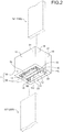
- the first terminal housing chamber 20 has two openings 21, 22 that are opposingly arranged ( FIG. 1 and FIG. 2 ). Furthermore, the first terminal housing chamber 20 serves either of the two openings 21, 22 as an insertion opening for the electrical connection part 121 of the first counterpart terminal 120. Thus, the first terminal housing chamber 20 can cause the electrical connection part 121 that is inserted from either of the two openings 21, 22 to project from the other opening. In other words, the electrical connection part 121 can be inserted through the first terminal housing chamber 20 through the two openings 21, 22.
- the relay terminal 1 can change a relative position of the first counterpart terminal 120 with respect to the first terminal housing chamber 20 in the insertion/extraction direction (i.e., a housed position of the electrical connection part 121), while ensuring the electrical connection state between the first terminal housing chamber 20 and the first counterpart terminal 120.
- the relay terminal 1 can ensure the electrical connection state between the first terminal housing chamber 20 and the first counterpart terminal 120 even when the housed position of the electrical connection part 121 in the insertion/extraction direction has changed. Accordingly, the relay terminal 1 can absorb tolerance and variation between the first terminal housing chamber 20 and the first counterpart terminal 120 in the insertion/extraction direction.
- the exemplified first terminal housing chamber 20 serves the opening 21 as the insertion opening for the electrical connection part 121 of the first counterpart terminal 120.
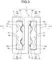
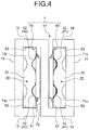
- the first terminal housing chamber 20 includes a first elastic contact part 41 to be physically and electrically connected with the electrical connection part 121 of the first counterpart terminal 120 ( FIG. 3 to FIG. 5 ).
- the first elastic contact part 41 is a contact part that is formed to have elasticity.
- the first elastic contact part 41 contacts the electrical connection part 121 of the first counterpart terminal 120 housed in the first terminal housing chamber 20, while imparting resilient force in a direction orthogonal to the insertion direction (insertion/extraction direction) of the first counterpart terminal 120.
- the relay terminal 1 can change a relative position of the first counterpart terminal 120 with respect to the first terminal housing chamber 20 in the resilient force imparting direction of the first elastic contact part 41, while ensuring the electrical connection state between the first terminal housing chamber 20 and the first counterpart terminal 120 through the first elastic contact part 41. Accordingly, the relay terminal 1 can absorb tolerance and variation between the first terminal housing chamber 20 and the first counterpart terminal 120 in the resilient force imparting direction.
- the first elastic contact part 41 may be integrally formed on a wall surface of the first terminal housing chamber 20, or may be integrally formed with another part housed in the first terminal housing chamber 20.
- the first terminal housing chamber 20 has gaps g1, g2 with respect to the electrical connection part 121 of the housed first counterpart terminal 120, in a direction (hereinafter, the "gap direction") orthogonal to the insertion direction (insertion/extraction direction) of the first counterpart terminal 120 and the resilient force imparting direction of the first elastic contact part 41 ( FIG. 7 ).
- the first elastic contact part 41 is arranged so as to contact the electrical connection part 121 of the first counterpart terminal 120 while imparting resilient force thereto, even when the electrical connection part 121 moves relatively to the first terminal housing chamber 20 by the gaps g1, g2 at a maximum.
- the relay terminal 1 can change a relative position of the first counterpart terminal 120 with respect to the first terminal housing chamber 20 in the gap direction, while ensuring the electrical connection state between the first terminal housing chamber 20 and the first counterpart terminal 120 through the first elastic contact part 41. Accordingly, the relay terminal 1 can absorb tolerance and variation between the first terminal housing chamber 20 and the first counterpart terminal 120 in the gap direction.
- the second terminal housing chamber 30 is formed in a shape that conforms to the shape of an electrical connection part 221 of the second counterpart terminal 220 such that the electrical connection part 221 can be inserted and extracted.
- the second terminal housing chamber 30 does not necessarily have a shape equivalent to the first terminal housing chamber 20.
- the electrical connection part 221 of the exemplified second counterpart terminal 220 is formed in a rectangular plate shape (i.e., a male tab shape) similar to the electrical connection part 121 of the first counterpart terminal 120, as will be described later.
- the second terminal housing chamber 30 is formed to have a cuboid shape that is equivalent to the first terminal housing chamber 20.
- the electrical connection with the second counterpart terminal 220 is achieved by inserting and housing the electrical connection part 221 along the insertion direction.
- the electrical connection with the second counterpart terminal 220 is released by extracting the housed electrical connection part 221 along the extraction direction.
- the insertion/extraction direction of the electrical connection part 221 of the second counterpart terminal 220 with respect to the second terminal housing chamber 30 will be collectively referred to as the "insertion/extraction direction" herein.
- the second terminal housing chamber 30 has two openings 31, 32 that are opposingly arranged ( FIG. 1 and FIG. 2 ). Furthermore, the second terminal housing chamber 30 serves either of the two openings 31, 32 as an insertion opening for the electrical connection part 221 of the second counterpart terminal 220. Thus, the second terminal housing chamber 30 can cause the electrical connection part 221 that is inserted from either of the two openings 31, 32 to project from the other opening. In other words, the electrical connection part 221 can be inserted through the second terminal housing chamber 30 through the two openings 31, 32, as in the case of the first terminal housing chamber 20.
- the relay terminal 1 can change a relative position of the second counterpart terminal 220 with respect to the second terminal housing chamber 30 in the insertion/extraction direction (i.e., a housed position of the electrical connection part 221), while ensuring the electrical connection state between the second terminal housing chamber 30 and the second counterpart terminal 220.
- the relay terminal 1 can ensure the electrical connection state between the second terminal housing chamber 30 and the second counterpart terminal 220 even when the housed position of the electrical connection part 221 in the insertion/extraction direction has changed. Accordingly, the relay terminal 1 can absorb tolerance and variation between the second terminal housing chamber 30 and the second counterpart terminal 220 in the insertion/extraction direction.
- the first terminal housing chamber 20 and the second terminal housing chamber 30 may be formed such that the insertion/extraction direction of the first counterpart terminal 120 and the insertion/extraction direction of the second counterpart terminal 220 are the same as each other, or may be formed such that the respective insertion/extraction directions are different from each other. Furthermore, the first terminal housing chamber 20 and the second terminal housing chamber 30 are formed such that, when the respective insertion/extraction directions are the same as each other, the insertion direction of the first counterpart terminal 120 and the insertion direction of the second counterpart terminal 220 are the same or opposite from each other.
- the exemplified first terminal housing chamber 20 and second terminal housing chamber 30 are formed such that the insertion direction of the first counterpart terminal 120 and the insertion direction of the second counterpart terminal 220 are opposite from each other.
- the exemplified second terminal housing chamber 30 serves the opening 32 as an insertion opening for the electrical connection part 221 of the second counterpart terminal 220.
- the second terminal housing chamber 30 includes a second elastic contact part 42 to be physically and electrically connected with the electrical connection part 221 of the second counterpart terminal 220 ( FIG. 3 to FIG. 5 ).
- the second elastic contact part 42 is a contact part that is formed to have elasticity, as in the case of the first elastic contact part 41.
- the second elastic contact part 42 may have a shape equivalent to the first elastic contact part 41, or may have a shape different from the first elastic contact part 41.
- the second elastic contact part 42 contacts the electrical connection part 221 of the second counterpart terminal 220 housed in the second terminal housing chamber 30, while imparting resilient force in a direction orthogonal to the insertion direction (insertion/extraction direction) of the second counterpart terminal 220.
- the relay terminal 1 can change a relative position of the second counterpart terminal 220 with respect to the second terminal housing chamber 30 in the resilient force imparting direction of the second elastic contact part 42, while ensuring the electrical connection state between the second terminal housing chamber 30 and the second counterpart terminal 220 through the second elastic contact part 42. Accordingly, the relay terminal 1 can absorb tolerance and variation between the second terminal housing chamber 30 and the second counterpart terminal 220 in the resilient force imparting direction.
- the second elastic contact part 42 may be integrally formed on a wall surface of the second terminal housing chamber 30, or may be integrally formed with another part housed in the second terminal housing chamber 30.
- the second terminal housing chamber 30 has gaps g3, g4 with respect to the electrical connection part 221 of the housed second counterpart terminal 220, in a direction (hereinafter, the "gap direction") orthogonal to the insertion direction (insertion/extraction direction) of the second counterpart terminal 220 and the resilient force imparting direction of the second elastic contact part 42 ( FIG. 7 ).
- the second elastic contact part 42 is arranged so as to contact the electrical connection part 221 while imparting resilient force thereto, even when the electrical connection part 221 of the second counterpart terminal 220 moves relatively to the second terminal housing chamber 30 by the gaps g3, g4 at a maximum.
- the relay terminal 1 can change a relative position of the second counterpart terminal 220 with respect to the second terminal housing chamber 30 in the gap direction, while ensuring the electrical connection state between the second terminal housing chamber 30 and the second counterpart terminal 220 through the second elastic contact part 42. Accordingly, the relay terminal 1 can absorb tolerance and variation between the second terminal housing chamber 30 and the second counterpart terminal 220 in the gap direction.
- the relay terminal 1 in the relay terminal 1, the first terminal housing chamber 20 is formed such that the electrical connection part 121 of the first counterpart terminal 120 is relatively moved in each of three directions orthogonal to one another, and the second terminal housing chamber 30 is formed such that the electrical connection part 221 of the second counterpart terminal 220 is relatively moved in each of the three directions orthogonal to one another.
- the relay terminal 1 can absorb tolerance and variation between the first terminal housing chamber 20 and the first counterpart terminal 120 in each of the three directions orthogonal to one another, and can absorb tolerance and variation between the second terminal housing chamber 30 and the second counterpart terminal 220 in each of the three directions orthogonal to one another.
- the relay terminal 1 can provide a desired electrical connection state between the first terminal housing chamber 20 and the first counterpart terminal 120, and can provide a desired electrical connection state between the second terminal housing chamber 30 and the second counterpart terminal 220. Therefore, the electrical connection state between the first counterpart terminal 120 and the second counterpart terminal 220 can be improved.
- the terminal body 10 of the relay terminal 1 has first to third electrical connection bodies 11 to 13 that are arranged in parallel with intervals from one another, and coupling bodies 14, 15 that integrate these first to third electrical connection bodies 11 to 13 ( FIG. 1 to FIG. 7 ).
- the exemplified first to third electrical connection bodies 11 to 13 and the coupling bodies 14, 15 are each formed in rectangular flat plate shapes.
- the exemplified first to third electrical connection bodies 11 to 13 are each formed in equivalent shapes.
- the first electrical connection body 11 and the second electrical connection body 12 are opposingly arranged with an interval from each other, and one sides of the opposingly arranged first electrical connection body 11 and the second electrical connection body 12 are coupled with the coupling body 14 ( FIG. 1 to FIG. 7 ).
- the first electrical connection body 11 and the second electrical connection body 12 are opposingly arranged by setting the rectangular flat surfaces to face each other.
- the coupling body 14 is set orthogonal to each of the first electrical connection body 11 and the second electrical connection body 12.
- the first terminal housing chamber 20 is formed by utilizing a space between the first electrical connection body 11 and the second electrical connection body 12.
- the terminal body 10 has a wall body 16 that is erected from the other side of the first electrical connection body 11 toward the other side of the second electrical connection body 12 ( FIG. 1 to FIG. 7 ).
- the wall body 16 is formed in a rectangular flat plate shape, and is set orthogonal to the first electrical connection body 11.
- the wall body 16 is arranged so as to oppose the coupling body 14 with an interval.
- a cuboid-shaped space that is surrounded by the first electrical connection body 11, the second electrical connection body 12, the coupling body 14, and the wall body 16 is utilized as the first terminal housing chamber 20.
- the rectangular-shaped opening 21 is formed with one ends of each of the first electrical connection body 11, the second electrical connection body 12, the coupling body 14, and the wall body 16, whereas the rectangular-shaped opening 22 is formed with the other ends of each of the first electrical connection body 11, the second electrical connection body 12, the coupling body 14, and the wall body 16.
- the gap between the first electrical connection body 11 and the second electrical connection body 12 is made larger than a plate thickness of the electrical connection part 121 of the first counterpart terminal 120.
- the coupling body 14 is arranged such that the gap g1 is formed between the coupling body 14 and the electrical connection part 121
- the wall body 16 is arranged such that the gap g2 is formed between the wall body 16 and the electrical connection part 121.
- the second electrical connection body 12 and the third electrical connection body 13 are opposingly arranged with an interval from each other, and the other sides of the opposingly arranged second electrical connection body 12 and the third electrical connection body 13 are coupled with the coupling body 15 ( FIG. 1 to FIG. 7 ).
- the second electrical connection body 12 and the third electrical connection body 13 are opposingly arranged by setting the rectangular flat surfaces to face each other.
- the coupling body 15 is set orthogonal to each of the second electrical connection body 12 and the third electrical connection body 13.
- the second terminal housing chamber 30 is formed by utilizing a space between the second electrical connection body 12 and the third electrical connection body 13.
- the terminal body 10 has a wall body 17 that is erected from one side of the third electrical connection body 13 toward one side of the second electrical connection body 12 ( FIG. 1 to FIG. 7 ).
- the wall body 17 is formed in a rectangular flat plate shape, and is set orthogonal to the third electrical connection body 13.
- the wall body 17 is arranged so as to oppose the coupling body 15 with an interval.
- a cuboid-shaped space that is surrounded by the second electrical connection body 12, the third electrical connection body 13, the coupling body 15, and the wall body 17 is utilized as the second terminal housing chamber 30.
- the rectangular-shaped opening 31 is formed with one ends of each of the second electrical connection body 12, the third electrical connection body 13, the coupling body 15, and the wall body 17, whereas the rectangular-shaped opening 32 is formed with the other ends of each of the second electrical connection body 12, the third electrical connection body 13, the coupling body 15, and the wall body 17.
- the gap between the second electrical connection body 12 and the third electrical connection body 13 is made larger than a plate thickness of the electrical connection part 221 of the second counterpart terminal 220.
- the coupling body 15 is arranged such that the gap g3 is formed between the coupling body 15 and the electrical connection part 221
- the wall body 17 is arranged such that the gap g4 is formed between the wall body 17 and the electrical connection part 221.
- the outer shape of the terminal body 10 in this specific example is formed in a cuboid shape by, for example, using a metal plate as a base material, and performing press molding in an S-shape.
- the terminal body 10 may have any shape, as long as it has the first to the third electrical connection bodies 11 to 13, the wall body 16, a wall body that is arranged so as to oppose the wall body 16 with an interval (e.g., coupling body 14), the wall body 17, and a wall body that is arranged so as to oppose the wall body 17 with an interval (e.g., coupling body 15).
- the terminal body 10 may have the first to the third electrical connection bodies 11 to 13, the wall body 16, the coupling body 15, and a wall body that connects one sides of the first electrical connection body 11 and the third electrical connection body 13 at the positions of the coupling body 14 and the wall body 17.
- the first elastic contact part 41 may be integrally formed on the wall surface of the first terminal housing chamber 20, or may be integrally formed with another part housed in the first terminal housing chamber 20.
- the second elastic contact part 42 may be integrally formed on the wall surface of the second terminal housing chamber 30, or may be integrally formed with another part housed in the second terminal housing chamber 30.
- the first elastic contact part 41 is integrally formed on the wall surface of the first terminal housing chamber 20
- at least one first elastic contact part 41 is formed in at least either of the first electrical connection body 11 and the second electrical connection body 12.
- the first elastic contact part 41 is formed in a shape having elasticity by being bent with press molding to project from at least either of the first electrical connection body 11 and the second electrical connection body 12 toward the first terminal housing chamber 20.
- the second elastic contact part 42 is integrally formed on the wall surface of the second terminal housing chamber 30, at least one second elastic contact part 42 is formed in at least either of the second electrical connection body 12 and the third electrical connection body 13.
- the second elastic contact part 42 is formed in a shape having elasticity by being bent with press molding to project from at least either of the second electrical connection body 12 and the third electrical connection body 13 toward the second terminal housing chamber 30.
- the relay terminal 1 in this case includes a first contact member that is assembled in the first terminal housing chamber 20, and a second contact member that is assembled in the second terminal housing chamber 30.
- the first contact member has the first elastic contact part 41.
- the second contact member has the second elastic contact part 42.
- the first contact member and the second contact member are intended to be used in common, and a contact member 50 to be utilized as the first contact member and the second contact member is provided ( FIG. 1 to FIG. 5 ).
- the contact member 50 is formed with, for example, press molding by using a metal plate as a base material, and is housed and fixed in each of the first terminal housing chamber 20 and the second terminal housing chamber 30.
- the contact member 50 has a main body 51 having a rectangular shape, a plurality of elastic contact parts 52 that are bent to project in the same direction from the main body 51 with press molding, and a plurality of fitting and fixing parts 53 that each project in the same direction as the elastic contact parts 52 from two sides that are opposingly arranged in the main body 51 ( FIG. 1 to FIG. 5 , FIG. 7 , and FIG. 8 ).
- the elastic contact parts 52 are portions to be utilized as the first elastic contact part 41 and the second elastic contact part 42, and are formed in shapes having elasticity by such bending.
- Each of the fitting and fixing parts 53 has a seat 53a that is formed in a rectangular shape, and an elastic piece part 53b that is bent to project to the opposite side of the elastic contact part 52 from the seat 53a with press molding ( FIG. 5 and FIG. 8 ).
- the contact member 50 is housed in the first terminal housing chamber 20 such that the elastic contact parts 52 project from the second electrical connection body 12 side to the first electrical connection body 11 side. Furthermore, the contact member 50 is housed in the first terminal housing chamber 20 such that resilient force acts on the coupling body 14 by the elastic piece part 53b on one side of the main body 51, and resilient force acts on the wall body 16 by the elastic piece part 53b on the other side of the main body 51. In this manner, the contact member 50 is fitted and fixed between the coupling body 14 and the wall body 16 in the state that the elastic contact parts 52 are arranged so as to oppose the first electrical connection body 11 with an interval. The contact member 50 is physically and electrically connected to the wall surface of the first terminal housing chamber 20 through at least the elastic piece part 53b.
- a plurality of indents (projecting parts) 11c that project toward the second electrical connection body 12 side, are formed in the exemplified first electrical connection body 11 ( FIG. 3 to FIG. 5 , and FIG. 7 ).
- two indents 11c that are extended in the insertion/extraction direction of the first counterpart terminal 120 are arranged with an interval, between the coupling body 14 and the wall body 16.
- the indents 11c are each arranged so as to oppose the elastic contact parts 52.
- the shapes and the arrangements of each of the elastic contact parts 52 and the indents 11c are set such that a minimum gap between the elastic contact parts 52 and the indents 11c in the first terminal housing chamber 20 is narrower than the plate thickness of the electrical connection part 121 of the first counterpart terminal 120.
- the gap g1 is formed between the fitting and fixing part 53 on the coupling body 14 side and the electrical connection part 121
- the gap g2 is formed between the fitting and fixing part 53 on the wall body 16 side and the electrical connection part 121.
- the contact member 50 is housed in the second terminal housing chamber 30 such that the elastic contact parts 52 project from the second electrical connection body 12 side to the third electrical connection body 13 side. Furthermore, the contact member 50 is housed in the second terminal housing chamber 30 such that resilient force acts on the coupling body 15 by the elastic piece part 53b on one side of the main body 51, and resilient force acts on the wall body 17 by the elastic piece part 53b on the other side of the main body 51. In this manner, the contact member 50 is fitted and fixed between the coupling body 15 and the wall body 17 in the state that the elastic contact parts 52 are arranged so as to oppose the third electrical connection body 13 with an interval. The contact member 50 is physically and electrically connected with the wall surface of the second terminal housing chamber 30 through at least the elastic piece part 53b.
- a plurality of indents (projecting parts) 13c that project to the second electrical connection body 12 side are formed in the exemplified third electrical connection body 13 ( FIG. 3 to FIG. 5 and FIG. 7 ).
- two indents 13c that are extended in the insertion/extraction direction of the second counterpart terminal 220 are arranged with an interval, between the coupling body 15 and the wall body 17.
- the indents 13c are each arranged so as to oppose the elastic contact parts 52.
- the shapes and the arrangements of each of the elastic contact parts 52 and the indents 13c are set such that a minimum gap between the elastic contact parts 52 and the indents 13c in the second terminal housing chamber 30 is narrower than the plate thickness of the electrical connection part 221 of the second counterpart terminal 220.
- the gap g3 is formed between the fitting and fixing part 53 on the coupling body 15 side and the electrical connection part 221
- the gap g4 is formed between the fitting and fixing part 53 on the wall body 17 side and the electrical connection part 221.
- the relay terminal 1 By forming the relay terminal 1 in this manner, in the relay terminal 1, the electrical connection part 121 of the first counterpart terminal 120 can be moved relatively to the first terminal housing chamber 20 in each of the three directions orthogonal to one another, and the electrical connection part 221 of the second counterpart terminal 220 can be moved relatively to the second terminal housing chamber 30 in each of the three directions orthogonal to one another. In this manner, the relay terminal 1 can absorb tolerance and variation between the first terminal housing chamber 20 and the first counterpart terminal 120 in each of the three directions orthogonal to one another, and can absorb tolerance and variation between the second terminal housing chamber 30 and the second counterpart terminal 220 in each of the three directions orthogonal to one another.
- the relay terminal 1 can provide a desired electrical connection state between the first terminal housing chamber 20 and the first counterpart terminal 120 through the first elastic contact parts 41 (elastic contact parts 52) and the indents 11c, and can provide a desired electrical connection state between the second terminal housing chamber 30 and the second counterpart terminal 220 through the second elastic contact parts 42 (elastic contact parts 52) and the indents 13c.
- the electrical connection state between the first counterpart terminal 120 and the second counterpart terminal 220 can be improved.
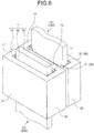
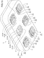
- the relay terminal 1 described above forms a relay connector 70 by being housed in an insulating housing 60 ( FIG. 9 to FIG. 12 ).
- the relay connector 70 includes at least one relay terminal 1.
- an example of the relay connector 70 will be described.
- the exemplified relay connector 70 includes a plurality of the relay terminals 1. In this example, six relay terminals 1 are included.
- the housing 60 has a terminal holding chamber 61 in which the relay terminals 1 are housed and held ( FIG. 9 to FIG. 12 ).
- the housing 60 has the terminal holding chamber 61 for each of the relay terminals 1.
- the terminal holding chamber 61 has an insertion opening 62 ( FIG. 9 , FIG. 11 , and FIG. 12 ) for the first counterpart terminal 120, and an insertion opening 63 ( FIG. 10 ) for the second counterpart terminal 220.
- the insertion opening 62 for the first counterpart terminal 120 is arranged so as to oppose the insertion opening (opening 21) for the first counterpart terminal 120 in the first terminal housing chamber 20 of the relay terminal 1.
- the insertion opening 63 for the second counterpart terminal 220 is arranged so as to oppose the insertion opening (opening 32) for the second counterpart terminal 220 in the second terminal housing chamber 30 of the relay terminal 1.
- the exemplified terminal holding chamber 61 has an opening 64 ( FIG. 9 , FIG. 11 , and FIG. 12 ) that is arranged so as to oppose the openings 21, 31 of the terminal body 10, and an opening 65 ( FIG. 10 ) that is arranged so as to oppose the openings 22, 32 of the terminal body 10.
- the terminal holding chamber 61 utilizes at least either of the openings 64, 65 as the insertion openings 62, 63 in accordance with the insertion direction of the first counterpart terminal 120 and the insertion direction of the second counterpart terminal 220.
- the insertion direction of the first counterpart terminal 120 and the insertion direction of the second counterpart terminal 220 are opposite from each other.
- a portion of the opening 64 is utilized as the insertion opening 62
- a portion of the opening 65 is utilized as the insertion opening 63.
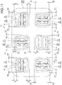
- the terminal holding chamber 61 has a first gap G1 that is configured to relatively move the relay terminal 1 housed in the terminal holding chamber 61 in the resilient force imparting direction of the first elastic contact parts 41 (elastic contact parts 52), and a second gap G2 that is configured to relatively move the relay terminal 1 housed in the terminal holding chamber 61 in a direction orthogonal to the insertion direction (insertion/extraction direction) of the first counterpart terminal 120 and the resilient force imparting direction of the first elastic contact parts 41 (elastic contact parts 52) ( FIG. 11 ).
- the first gap G1 and the second gap G2 are each provided at two positions.
- the relay terminal 1 in the terminal holding chamber 61, the relay terminal 1 can be moved relatively to the terminal holding chamber 61, in both directions orthogonal to the insertion/extraction direction of the first and the second counterpart terminals 120, 220.
- the openings 64, 65 are made smaller than the relay terminal 1 in consideration of the relative movement, such that the relay terminal 1 can be continuously held in the terminal holding chamber 61.
- the exemplified housing 60 includes a housing member 60A and a lid member 60B ( FIG. 9 , FIG. 10 , and FIG. 12 ).
- the housing 60 forms the terminal holding chamber 61 with the housing member 60A and the lid member 60B.
- the housing member 60A and the lid member 60B are made of insulating materials such as synthetic resins.
- a main space for the terminal holding chamber 61 and the opening 65 (insertion opening 63) are formed in the housing member 60A.
- the opening 64 (insertion opening 62) is formed in the lid member 60B.
- the lid member 60B closes the periphery of the opening of the main space for the terminal holding chamber 61 while leaving the opening 64 (insertion opening 62), by being fit on the housing member 60A in which the relay terminals 1 are housed.
- each of the relay terminals 1 can be moved relatively to the terminal holding chamber 61 in both directions orthogonal to the insertion/extraction direction of the first and the second counterpart terminals 120, 220. Furthermore, the relay connector 70 can move the electrical connection part 121 of the first counterpart terminal 120 relatively to the first terminal housing chamber 20 in each of the three directions orthogonal to one another, and can move the electrical connection part 221 of the second counterpart terminal 220 relatively to the second terminal housing chamber 30 in each of the three directions orthogonal to one another, for each of the relay terminals 1.
- the relay connector 70 can absorb tolerance and variation between the first terminal housing chamber 20 and the first counterpart terminal 120 in each of the three directions orthogonal to one another, and can absorb tolerance and variation between the second terminal housing chamber 30 and the second counterpart terminal 220 in each of the three directions orthogonal to one another, for each of the relay terminals 1. Furthermore, the relay connector 70 can absorb tolerance and variation among a plurality of the first counterpart terminals 120 in the three directions orthogonal to one another, and can absorb tolerance and variation among a plurality of the second counterpart terminals 220 in the three directions orthogonal to one another, due to the working effect of the relay terminal 1 alone combined with the relative movement of the relay terminal 1.
- the relay connector 70 can provide a desired electrical connection state between the first terminal housing chamber 20 and the first counterpart terminal 120 through the first elastic contact parts 41 (elastic contact parts 52) and the indents 11c, and can provide a desired electrical connection state between the second terminal housing chamber 30 and the second counterpart terminal 220 through the second elastic contact parts 42 (elastic contact parts 52) and the indents 13c, for each of the relay terminals 1.
- the relay connector 70 can improve the electrical connection state between the first counterpart terminal 120 and the second counterpart terminal 220 in all the relay terminals 1.
- a pair of the first counterpart terminal 120 and the second counterpart terminal 220 is connected to each relay terminal 1 by being arranged in a direction orthogonal to the insertion/extraction direction.
- the body size in the insertion/extraction direction can be made small.
- the relay connector 70 is used for electrically connecting an inverter and a rotating machine, in a vehicle using a rotating machine as driving force such as an electric automobile or hybrid vehicle.
- the inverter (not illustrated) is provided with a first mating connector 110 that includes the first counterpart terminal 120 ( FIG. 13 to FIG. 15 ).
- the rotating machine (not illustrated) is provided with a second mating connector 210 that includes the second counterpart terminal 220 ( FIG. 13 to FIG. 15 ).
- the relay connector 70 By physically and electrically connecting the relay connector 70 to each of the first mating connector 110 and the second mating connector 210, the first mating connector 110 and the second mating connector 210 are electrically connected.
- the exemplified first mating connector 110 includes six first counterpart terminals 120 (first counterpart terminals 120A to 120F) ( FIG. 14 ).
- the first counterpart terminals 120A to 120F are each housed in an insulating housing 130 in the state that the electrical connection parts 121 project in the same direction.
- the exemplified second mating connector 210 includes six second counterpart terminals 220 (second counterpart terminals 220A to 220F) ( FIG. 13 ).
- the second counterpart terminals 220A to 220F are each housed in an insulating housing 230 in the state that the electrical connection parts 221 project in the same direction.
- the first mating connector 110 and the second mating connector 210 sandwich the relay connector 70, and the pair of the first counterpart terminal 120 and the second counterpart terminal 220 is connected to each of the relay terminals 1.
- each of the six relay terminals 1 in the terminal holding chamber 61 by adjusting the housed state of each of the six relay terminals 1 in the terminal holding chamber 61 such as by shifting each of them by 90 degrees, at least two of the first counterpart terminals 120A to 120F and the second counterpart terminals 220A to 220F can be used in common.
- the same things are used for the first counterpart terminals 120B, 120C, and the second counterpart terminals 220A, 220D ( FIG. 16 ) .
- the first terminal housing chamber is formed such that the first counterpart terminal is relatively moved in each of the three directions orthogonal to one another
- the second terminal housing chamber is formed such that the second counterpart terminal is relatively moved in each of the three directions orthogonal to one another.
- the relay terminal and the relay connector can absorb tolerance and variation between the first terminal housing chamber and the first counterpart terminal in each of the three directions orthogonal to one another, and can absorb tolerance and variation between the second terminal housing chamber and the second counterpart terminal in each of the three directions that are orthogonal to one another.
- the relay terminal and the relay connector can provide a desired electrical connection state between the first terminal housing chamber and the first counterpart terminal, and can provide a desired electrical connection state between the second terminal housing chamber and the second counterpart terminal. Therefore, the electrical connection state between the first counterpart terminal and the second counterpart terminal can be improved.
Landscapes
- Engineering & Computer Science (AREA)
- Manufacturing & Machinery (AREA)
- Coupling Device And Connection With Printed Circuit (AREA)
- Details Of Connecting Devices For Male And Female Coupling (AREA)
- Connecting Device With Holders (AREA)
Abstract
Description
- The present invention relates to a relay terminal and a relay connector.
- Conventionally, a relay terminal and a relay connector that electrically connect two objects to be electrically connected have been known. For example, Japanese Patent Application Laid-open No.
2009-99429 2009-99429 2009-99429 - Meanwhile, a relay terminal has multi-directional tolerance and variation between each of counterpart terminals to be connected by itself. Thus, the relay terminal is desired to be such a relay terminal that can absorb the multi-directional tolerance and variation in order to improve an electrical connection state of the respective counterpart terminals.
- Therefore, an objective of the present invention is to provide a relay terminal and a relay connector that are capable of absorbing multi-directional tolerance and variation between counterpart terminals.
- In order to achieve the above mentioned object, a relay terminal according to one aspect of the present invention includes a terminal body including a first terminal housing chamber into which a first counterpart terminal is inserted and housed, and a second terminal housing chamber into which a second counterpart terminal is inserted and housed, wherein the first terminal housing chamber serves either of two openings that are opposingly arranged as an insertion opening for the first counterpart terminal, and includes a first elastic contact part that contacts the first counterpart terminal housed in the first terminal housing chamber while imparting resilient force in a direction orthogonal to an insertion direction of the first counterpart terminal, and a gap with respect to the first counterpart terminal housed in the first terminal housing chamber in a direction orthogonal to the insertion direction of the first counterpart terminal and the resilient force imparting direction of the first elastic contact part, and the second terminal housing chamber serves either of two openings that are opposingly arranged as an insertion opening for the second counterpart terminal, and includes a second elastic contact part that contacts the second counterpart terminal housed in the second terminal housing chamber while imparting resilient force in a direction orthogonal to an insertion direction of the second counterpart terminal, and a gap with respect to the second counterpart terminal housed in the second terminal housing chamber in a direction orthogonal to the insertion direction of the second counterpart terminal and the resilient force imparting direction of the second elastic contact part.
- According to another aspect of the present invention, in the relay terminal, it is possible to configure that the first terminal housing chamber and the second terminal housing chamber are formed such that the insertion direction of the first counterpart terminal and the insertion direction of the second counterpart terminal are the same or are opposite from each other.
- According to still another aspect of the present invention, in the relay terminal, it is possible to configure that the terminal body includes first to third electrical connection bodies that are arranged in parallel with intervals from one another, and a coupling body that integrates the first to the third electrical connection bodies, the first terminal housing chamber is formed by utilizing a space between the first electrical connection body and the second electrical connection body that are opposingly arranged with an interval from each other, and the second terminal housing chamber is formed by utilizing a space between the second electrical connection body and the third electrical connection body that are opposingly arranged with an interval from each other.
- According to still another aspect of the present invention, in the relay terminal, it is possible to configure that the first elastic contact part is formed in at least either of the first electrical connection body and the second electrical connection body, and the second elastic contact part is formed in at least either of the second electrical connection body and the third electrical connection body.
- According to still another aspect of the present invention, in the relay terminal, it is possible to further include that a first contact member assembled in the first terminal housing chamber, and a second contact member assembled in the second terminal housing chamber, wherein the first contact member has the first elastic contact part, and the second contact member has the second elastic contact part.
- In order to achieve the above mentioned object, a relay connector according to still another aspect of the present invention includes a relay terminal; and a housing including a terminal holding chamber in which the relay terminal is housed and held, wherein the relay terminal includes a terminal body including a first terminal housing chamber into which a first counterpart terminal is inserted and housed, and a second terminal housing chamber into which a second counterpart terminal is inserted and housed, the first terminal housing chamber serves either of two openings that are opposingly arranged as an insertion opening for the first counterpart terminal, and includes a first elastic contact part that contacts the first counterpart terminal housed in the first terminal housing chamber while imparting resilient force to a direction orthogonal to an insertion direction of the first counterpart terminal, and a gap with respect to the first counterpart terminal housed in the first terminal housing chamber in a direction orthogonal to the insertion direction of the first counterpart terminal and the resilient force imparting direction of the first elastic contact part, the second terminal housing chamber serves either of two openings that are opposingly arranged as an insertion opening for the second counterpart terminal, and includes a second elastic contact part that contacts the second counterpart terminal housed in the second terminal housing chamber while imparting resilient force in a direction orthogonal to an insertion direction of the second counterpart terminal, and a gap with respect to the second counterpart terminal housed in the second terminal housing chamber in a direction orthogonal to the insertion direction of the second counterpart terminal and the resilient force imparting direction of the second elastic contact part, the first terminal housing chamber and the second terminal housing chamber are formed such that the insertion direction of the first counterpart terminal and the insertion direction of the second counterpart terminal are the same or are different from each other, and the terminal holding chamber has an insertion opening for the first counterpart terminal that is arranged so as to oppose the insertion opening for the first counterpart terminal in the first terminal housing chamber, an insertion opening for the second counterpart terminal that is arranged so as to oppose the insertion opening for the second counterpart terminal in the second terminal housing chamber, a first gap that is configured to relatively move the relay terminal housed in the terminal holding chamber in the resilient force imparting direction of the first elastic contact part, and a second gap that is configured to relatively move the relay terminal housed in the terminal holding chamber in a direction orthogonal to the insertion direction of the first counterpart terminal and the resilient force imparting direction of the first elastic contact part.
- The above and other objects, features, advantages and technical and industrial significance of this invention will be better understood by reading the following detailed description of presently preferred embodiments of the invention, when considered in connection with the accompanying drawings.
-
-
FIG. 1 is a perspective view of a relay terminal in an embodiment that is seen from one side of an opening; -
FIG. 2 is a perspective view of the relay terminal in the embodiment that is seen from the other side of the opening; -
FIG. 3 is a plan view of the relay terminal in the embodiment that is seen from the one side of the opening; -
FIG. 4 is a plan view of the relay terminal in the embodiment that is seen from the other side of the opening; -
FIG. 5 is a cross-section view at a line X-X inFIG. 3 ; -
FIG. 6 is a perspective view illustrating the relay terminal to which first and second counterpart terminals are connected; -
FIG. 7 is a plan view illustrating the relay terminal to which the first and the second counterpart terminals are connected; -
FIG. 8 is a perspective view illustrating a contact member; -
FIG. 9 is a perspective view illustrating a relay connector in the embodiment; -
FIG. 10 is a perspective view of the relay connector in the embodiment that is seen from another angle; -
FIG. 11 is a plan view of the relay connector in the embodiment that is seen from the one side of the opening; -
FIG. 12 is an exploded perspective view of the relay connector in the embodiment; -
FIG. 13 is a perspective view illustrating the relay connector before connection of the first and the second counterpart terminals; -
FIG. 14 is a perspective view of the relay connector before connection of the first and the second counterpart terminals that is seen from another angle; -
FIG. 15 is a perspective view illustrating the relay connector after connection of the first and the second counterpart terminals; and -
FIG. 16 is a perspective view illustrating the first and the second counterpart terminals. - Hereinafter, an embodiment of a relay terminal and a relay connector according to the present invention is described in detail with reference to the drawings. The present invention is not limited to this embodiment.
- An embodiment of the relay terminal and the relay connector according to the present invention is described based on
FIG. 1 to FIG. 16 . -
Reference sign 1 inFIG. 1 to FIG. 7 denotes the relay terminal of the present embodiment. - The
relay terminal 1 is a terminal that connects afirst counterpart terminal 120 and asecond counterpart terminal 220, and that allows a physical and electrical connection therebetween. Therelay terminal 1 includes at least a conductiveterminal body 10 that is made of a conductive material such as metal (FIG. 1 to FIG. 7 ). Theterminal body 10 has a firstterminal housing chamber 20 into which thefirst counterpart terminal 120 is inserted and housed, and a secondterminal housing chamber 30 into which thesecond counterpart terminal 220 is inserted and housed (FIG. 1 to FIG. 7 ). - The first
terminal housing chamber 20 is formed in a shape that conforms to the shape of anelectrical connection part 121 of thefirst counterpart terminal 120 such that theelectrical connection part 121 can be inserted or extracted. Theelectrical connection part 121 of thefirst counterpart terminal 120 is formed in a rectangular plate shape (i.e., a male tab shape), as will be described later. Thus, the firstterminal housing chamber 20 is formed in a cuboid shape. In the firstterminal housing chamber 20, the electrical connection with thefirst counterpart terminal 120 is achieved by inserting and housing theelectrical connection part 121 along the insertion direction. In addition, in the firstterminal housing chamber 20, the electrical connection with thefirst counterpart terminal 120 is released by extracting the housedelectrical connection part 121 along the extraction direction. The insertion/extraction direction of theelectrical connection part 121 of thefirst counterpart terminal 120 with respect to the firstterminal housing chamber 20 will be collectively referred to as the "insertion/extraction direction" herein. - The first
terminal housing chamber 20 has twoopenings FIG. 1 andFIG. 2 ). Furthermore, the firstterminal housing chamber 20 serves either of the twoopenings electrical connection part 121 of thefirst counterpart terminal 120. Thus, the firstterminal housing chamber 20 can cause theelectrical connection part 121 that is inserted from either of the twoopenings electrical connection part 121 can be inserted through the firstterminal housing chamber 20 through the twoopenings relay terminal 1 can change a relative position of thefirst counterpart terminal 120 with respect to the firstterminal housing chamber 20 in the insertion/extraction direction (i.e., a housed position of the electrical connection part 121), while ensuring the electrical connection state between the firstterminal housing chamber 20 and thefirst counterpart terminal 120. For example, by setting an interval of the twoopenings terminal housing chamber 20 shorter than the length of theelectrical connection part 121 in the insertion/extraction direction, therelay terminal 1 can ensure the electrical connection state between the firstterminal housing chamber 20 and thefirst counterpart terminal 120 even when the housed position of theelectrical connection part 121 in the insertion/extraction direction has changed. Accordingly, therelay terminal 1 can absorb tolerance and variation between the firstterminal housing chamber 20 and thefirst counterpart terminal 120 in the insertion/extraction direction. - The exemplified first
terminal housing chamber 20 serves theopening 21 as the insertion opening for theelectrical connection part 121 of thefirst counterpart terminal 120. - Furthermore, the first
terminal housing chamber 20 includes a firstelastic contact part 41 to be physically and electrically connected with theelectrical connection part 121 of the first counterpart terminal 120 (FIG. 3 to FIG. 5 ). The firstelastic contact part 41 is a contact part that is formed to have elasticity. The firstelastic contact part 41 contacts theelectrical connection part 121 of thefirst counterpart terminal 120 housed in the firstterminal housing chamber 20, while imparting resilient force in a direction orthogonal to the insertion direction (insertion/extraction direction) of thefirst counterpart terminal 120. Thus, therelay terminal 1 can change a relative position of thefirst counterpart terminal 120 with respect to the firstterminal housing chamber 20 in the resilient force imparting direction of the firstelastic contact part 41, while ensuring the electrical connection state between the firstterminal housing chamber 20 and thefirst counterpart terminal 120 through the firstelastic contact part 41. Accordingly, therelay terminal 1 can absorb tolerance and variation between the firstterminal housing chamber 20 and thefirst counterpart terminal 120 in the resilient force imparting direction. - The first
elastic contact part 41 may be integrally formed on a wall surface of the firstterminal housing chamber 20, or may be integrally formed with another part housed in the firstterminal housing chamber 20. - Furthermore, the first
terminal housing chamber 20 has gaps g1, g2 with respect to theelectrical connection part 121 of the housedfirst counterpart terminal 120, in a direction (hereinafter, the "gap direction") orthogonal to the insertion direction (insertion/extraction direction) of thefirst counterpart terminal 120 and the resilient force imparting direction of the first elastic contact part 41 (FIG. 7 ). For example, in the firstterminal housing chamber 20, the firstelastic contact part 41 is arranged so as to contact theelectrical connection part 121 of thefirst counterpart terminal 120 while imparting resilient force thereto, even when theelectrical connection part 121 moves relatively to the firstterminal housing chamber 20 by the gaps g1, g2 at a maximum. Thus, therelay terminal 1 can change a relative position of thefirst counterpart terminal 120 with respect to the firstterminal housing chamber 20 in the gap direction, while ensuring the electrical connection state between the firstterminal housing chamber 20 and thefirst counterpart terminal 120 through the firstelastic contact part 41. Accordingly, therelay terminal 1 can absorb tolerance and variation between the firstterminal housing chamber 20 and thefirst counterpart terminal 120 in the gap direction. - The second
terminal housing chamber 30 is formed in a shape that conforms to the shape of anelectrical connection part 221 of thesecond counterpart terminal 220 such that theelectrical connection part 221 can be inserted and extracted. The secondterminal housing chamber 30 does not necessarily have a shape equivalent to the firstterminal housing chamber 20. However, theelectrical connection part 221 of the exemplifiedsecond counterpart terminal 220 is formed in a rectangular plate shape (i.e., a male tab shape) similar to theelectrical connection part 121 of thefirst counterpart terminal 120, as will be described later. Thus, the secondterminal housing chamber 30 is formed to have a cuboid shape that is equivalent to the firstterminal housing chamber 20. In the secondterminal housing chamber 30, the electrical connection with thesecond counterpart terminal 220 is achieved by inserting and housing theelectrical connection part 221 along the insertion direction. In addition, in the secondterminal housing chamber 30, the electrical connection with thesecond counterpart terminal 220 is released by extracting the housedelectrical connection part 221 along the extraction direction. The insertion/extraction direction of theelectrical connection part 221 of thesecond counterpart terminal 220 with respect to the secondterminal housing chamber 30 will be collectively referred to as the "insertion/extraction direction" herein. - The second
terminal housing chamber 30 has twoopenings FIG. 1 andFIG. 2 ). Furthermore, the secondterminal housing chamber 30 serves either of the twoopenings electrical connection part 221 of thesecond counterpart terminal 220. Thus, the secondterminal housing chamber 30 can cause theelectrical connection part 221 that is inserted from either of the twoopenings electrical connection part 221 can be inserted through the secondterminal housing chamber 30 through the twoopenings terminal housing chamber 20. In this manner, therelay terminal 1 can change a relative position of thesecond counterpart terminal 220 with respect to the secondterminal housing chamber 30 in the insertion/extraction direction (i.e., a housed position of the electrical connection part 221), while ensuring the electrical connection state between the secondterminal housing chamber 30 and thesecond counterpart terminal 220. For example, by setting an interval of the twoopenings terminal housing chamber 30 shorter than the length of theelectrical connection part 221 in the insertion/extraction direction, therelay terminal 1 can ensure the electrical connection state between the secondterminal housing chamber 30 and thesecond counterpart terminal 220 even when the housed position of theelectrical connection part 221 in the insertion/extraction direction has changed. Accordingly, therelay terminal 1 can absorb tolerance and variation between the secondterminal housing chamber 30 and thesecond counterpart terminal 220 in the insertion/extraction direction. - In this regard, in the
relay terminal 1, the firstterminal housing chamber 20 and the secondterminal housing chamber 30 may be formed such that the insertion/extraction direction of thefirst counterpart terminal 120 and the insertion/extraction direction of thesecond counterpart terminal 220 are the same as each other, or may be formed such that the respective insertion/extraction directions are different from each other. Furthermore, the firstterminal housing chamber 20 and the secondterminal housing chamber 30 are formed such that, when the respective insertion/extraction directions are the same as each other, the insertion direction of thefirst counterpart terminal 120 and the insertion direction of thesecond counterpart terminal 220 are the same or opposite from each other. The exemplified firstterminal housing chamber 20 and secondterminal housing chamber 30 are formed such that the insertion direction of thefirst counterpart terminal 120 and the insertion direction of thesecond counterpart terminal 220 are opposite from each other. Thus, the exemplified secondterminal housing chamber 30 serves theopening 32 as an insertion opening for theelectrical connection part 221 of thesecond counterpart terminal 220. - Furthermore, the second
terminal housing chamber 30 includes a secondelastic contact part 42 to be physically and electrically connected with theelectrical connection part 221 of the second counterpart terminal 220 (FIG. 3 to FIG. 5 ). The secondelastic contact part 42 is a contact part that is formed to have elasticity, as in the case of the firstelastic contact part 41. The secondelastic contact part 42 may have a shape equivalent to the firstelastic contact part 41, or may have a shape different from the firstelastic contact part 41. The secondelastic contact part 42 contacts theelectrical connection part 221 of thesecond counterpart terminal 220 housed in the secondterminal housing chamber 30, while imparting resilient force in a direction orthogonal to the insertion direction (insertion/extraction direction) of thesecond counterpart terminal 220. Thus, therelay terminal 1 can change a relative position of thesecond counterpart terminal 220 with respect to the secondterminal housing chamber 30 in the resilient force imparting direction of the secondelastic contact part 42, while ensuring the electrical connection state between the secondterminal housing chamber 30 and thesecond counterpart terminal 220 through the secondelastic contact part 42. Accordingly, therelay terminal 1 can absorb tolerance and variation between the secondterminal housing chamber 30 and thesecond counterpart terminal 220 in the resilient force imparting direction. - The second
elastic contact part 42 may be integrally formed on a wall surface of the secondterminal housing chamber 30, or may be integrally formed with another part housed in the secondterminal housing chamber 30. - Furthermore, the second
terminal housing chamber 30 has gaps g3, g4 with respect to theelectrical connection part 221 of the housedsecond counterpart terminal 220, in a direction (hereinafter, the "gap direction") orthogonal to the insertion direction (insertion/extraction direction) of thesecond counterpart terminal 220 and the resilient force imparting direction of the second elastic contact part 42 (FIG. 7 ). For example, in the secondterminal housing chamber 30, as in the case of the firstterminal housing chamber 20, the secondelastic contact part 42 is arranged so as to contact theelectrical connection part 221 while imparting resilient force thereto, even when theelectrical connection part 221 of thesecond counterpart terminal 220 moves relatively to the secondterminal housing chamber 30 by the gaps g3, g4 at a maximum. Thus, therelay terminal 1 can change a relative position of thesecond counterpart terminal 220 with respect to the secondterminal housing chamber 30 in the gap direction, while ensuring the electrical connection state between the secondterminal housing chamber 30 and thesecond counterpart terminal 220 through the secondelastic contact part 42. Accordingly, therelay terminal 1 can absorb tolerance and variation between the secondterminal housing chamber 30 and thesecond counterpart terminal 220 in the gap direction. - In this manner, in the
relay terminal 1, the firstterminal housing chamber 20 is formed such that theelectrical connection part 121 of thefirst counterpart terminal 120 is relatively moved in each of three directions orthogonal to one another, and the secondterminal housing chamber 30 is formed such that theelectrical connection part 221 of thesecond counterpart terminal 220 is relatively moved in each of the three directions orthogonal to one another. In other words, therelay terminal 1 can absorb tolerance and variation between the firstterminal housing chamber 20 and thefirst counterpart terminal 120 in each of the three directions orthogonal to one another, and can absorb tolerance and variation between the secondterminal housing chamber 30 and thesecond counterpart terminal 220 in each of the three directions orthogonal to one another. Accordingly, therelay terminal 1 can provide a desired electrical connection state between the firstterminal housing chamber 20 and thefirst counterpart terminal 120, and can provide a desired electrical connection state between the secondterminal housing chamber 30 and thesecond counterpart terminal 220. Therefore, the electrical connection state between thefirst counterpart terminal 120 and thesecond counterpart terminal 220 can be improved. - Hereinafter, a specific example of the
relay terminal 1 will be described. - The
terminal body 10 of therelay terminal 1 has first to thirdelectrical connection bodies 11 to 13 that are arranged in parallel with intervals from one another, andcoupling bodies electrical connection bodies 11 to 13 (FIG. 1 to FIG. 7 ). The exemplified first to thirdelectrical connection bodies 11 to 13 and thecoupling bodies electrical connection bodies 11 to 13 are each formed in equivalent shapes. - In the
terminal body 10, the firstelectrical connection body 11 and the secondelectrical connection body 12 are opposingly arranged with an interval from each other, and one sides of the opposingly arranged firstelectrical connection body 11 and the secondelectrical connection body 12 are coupled with the coupling body 14 (FIG. 1 to FIG. 7 ). The firstelectrical connection body 11 and the secondelectrical connection body 12 are opposingly arranged by setting the rectangular flat surfaces to face each other. Thecoupling body 14 is set orthogonal to each of the firstelectrical connection body 11 and the secondelectrical connection body 12. - The first
terminal housing chamber 20 is formed by utilizing a space between the firstelectrical connection body 11 and the secondelectrical connection body 12. In this regard, theterminal body 10 has awall body 16 that is erected from the other side of the firstelectrical connection body 11 toward the other side of the second electrical connection body 12 (FIG. 1 to FIG. 7 ). Thewall body 16 is formed in a rectangular flat plate shape, and is set orthogonal to the firstelectrical connection body 11. Thus, thewall body 16 is arranged so as to oppose thecoupling body 14 with an interval. In this specific example, a cuboid-shaped space that is surrounded by the firstelectrical connection body 11, the secondelectrical connection body 12, thecoupling body 14, and thewall body 16 is utilized as the firstterminal housing chamber 20. In the firstterminal housing chamber 20, the rectangular-shapedopening 21 is formed with one ends of each of the firstelectrical connection body 11, the secondelectrical connection body 12, thecoupling body 14, and thewall body 16, whereas the rectangular-shapedopening 22 is formed with the other ends of each of the firstelectrical connection body 11, the secondelectrical connection body 12, thecoupling body 14, and thewall body 16. - In the first
terminal housing chamber 20, the gap between the firstelectrical connection body 11 and the secondelectrical connection body 12 is made larger than a plate thickness of theelectrical connection part 121 of thefirst counterpart terminal 120. In addition, in the firstterminal housing chamber 20, thecoupling body 14 is arranged such that the gap g1 is formed between thecoupling body 14 and theelectrical connection part 121, and thewall body 16 is arranged such that the gap g2 is formed between thewall body 16 and theelectrical connection part 121. Thus, there will be no problem if thewall body 16 contacts the other side of the secondelectrical connection body 12. However, if a gap is provided with respect to the other side, the gap should be formed narrower than the plate thickness of theelectrical connection part 121. - In addition, in the
terminal body 10, the secondelectrical connection body 12 and the thirdelectrical connection body 13 are opposingly arranged with an interval from each other, and the other sides of the opposingly arranged secondelectrical connection body 12 and the thirdelectrical connection body 13 are coupled with the coupling body 15 (FIG. 1 to FIG. 7 ). The secondelectrical connection body 12 and the thirdelectrical connection body 13 are opposingly arranged by setting the rectangular flat surfaces to face each other. Thecoupling body 15 is set orthogonal to each of the secondelectrical connection body 12 and the thirdelectrical connection body 13. - The second
terminal housing chamber 30 is formed by utilizing a space between the secondelectrical connection body 12 and the thirdelectrical connection body 13. In this regard, theterminal body 10 has awall body 17 that is erected from one side of the thirdelectrical connection body 13 toward one side of the second electrical connection body 12 (FIG. 1 to FIG. 7 ). Thewall body 17 is formed in a rectangular flat plate shape, and is set orthogonal to the thirdelectrical connection body 13. Thus, thewall body 17 is arranged so as to oppose thecoupling body 15 with an interval. In this specific example, a cuboid-shaped space that is surrounded by the secondelectrical connection body 12, the thirdelectrical connection body 13, thecoupling body 15, and thewall body 17 is utilized as the secondterminal housing chamber 30. In the secondterminal housing chamber 30, the rectangular-shapedopening 31 is formed with one ends of each of the secondelectrical connection body 12, the thirdelectrical connection body 13, thecoupling body 15, and thewall body 17, whereas the rectangular-shapedopening 32 is formed with the other ends of each of the secondelectrical connection body 12, the thirdelectrical connection body 13, thecoupling body 15, and thewall body 17. - In the second
terminal housing chamber 30, the gap between the secondelectrical connection body 12 and the thirdelectrical connection body 13 is made larger than a plate thickness of theelectrical connection part 221 of thesecond counterpart terminal 220. In addition, in the secondterminal housing chamber 30, thecoupling body 15 is arranged such that the gap g3 is formed between thecoupling body 15 and theelectrical connection part 221, and thewall body 17 is arranged such that the gap g4 is formed between thewall body 17 and theelectrical connection part 221. Thus, there will be no problem if thewall body 17 contacts one side of the secondelectrical connection body 12. However, if a gap is provided with respect to the one side, the gap should be formed narrower than the plate thickness of theelectrical connection part 221. - The outer shape of the
terminal body 10 in this specific example is formed in a cuboid shape by, for example, using a metal plate as a base material, and performing press molding in an S-shape. Theterminal body 10 may have any shape, as long as it has the first to the thirdelectrical connection bodies 11 to 13, thewall body 16, a wall body that is arranged so as to oppose thewall body 16 with an interval (e.g., coupling body 14), thewall body 17, and a wall body that is arranged so as to oppose thewall body 17 with an interval (e.g., coupling body 15). For example, theterminal body 10 may have the first to the thirdelectrical connection bodies 11 to 13, thewall body 16, thecoupling body 15, and a wall body that connects one sides of the firstelectrical connection body 11 and the thirdelectrical connection body 13 at the positions of thecoupling body 14 and thewall body 17. - As previously described, the first
elastic contact part 41 may be integrally formed on the wall surface of the firstterminal housing chamber 20, or may be integrally formed with another part housed in the firstterminal housing chamber 20. In addition, the secondelastic contact part 42 may be integrally formed on the wall surface of the secondterminal housing chamber 30, or may be integrally formed with another part housed in the secondterminal housing chamber 30. - When the first
elastic contact part 41 is integrally formed on the wall surface of the firstterminal housing chamber 20, at least one firstelastic contact part 41 is formed in at least either of the firstelectrical connection body 11 and the secondelectrical connection body 12. For example, the firstelastic contact part 41 is formed in a shape having elasticity by being bent with press molding to project from at least either of the firstelectrical connection body 11 and the secondelectrical connection body 12 toward the firstterminal housing chamber 20. In addition, when the secondelastic contact part 42 is integrally formed on the wall surface of the secondterminal housing chamber 30, at least one secondelastic contact part 42 is formed in at least either of the secondelectrical connection body 12 and the thirdelectrical connection body 13. For example, the secondelastic contact part 42 is formed in a shape having elasticity by being bent with press molding to project from at least either of the secondelectrical connection body 12 and the thirdelectrical connection body 13 toward the secondterminal housing chamber 30. - In this specific example, the first
elastic contact part 41 and the secondelastic contact part 42 are provided as separate parts. Therelay terminal 1 in this case includes a first contact member that is assembled in the firstterminal housing chamber 20, and a second contact member that is assembled in the secondterminal housing chamber 30. The first contact member has the firstelastic contact part 41. The second contact member has the secondelastic contact part 42. In this regard, in therelay terminal 1 of this specific example, the first contact member and the second contact member are intended to be used in common, and acontact member 50 to be utilized as the first contact member and the second contact member is provided (FIG. 1 to FIG. 5 ). - The
contact member 50 is formed with, for example, press molding by using a metal plate as a base material, and is housed and fixed in each of the firstterminal housing chamber 20 and the secondterminal housing chamber 30. Thecontact member 50 has amain body 51 having a rectangular shape, a plurality ofelastic contact parts 52 that are bent to project in the same direction from themain body 51 with press molding, and a plurality of fitting and fixingparts 53 that each project in the same direction as theelastic contact parts 52 from two sides that are opposingly arranged in the main body 51 (FIG. 1 to FIG. 5 ,FIG. 7 , andFIG. 8 ). Theelastic contact parts 52 are portions to be utilized as the firstelastic contact part 41 and the secondelastic contact part 42, and are formed in shapes having elasticity by such bending. Sixelastic contact parts 52 are formed in themain body 51. Each of the fitting and fixingparts 53 has aseat 53a that is formed in a rectangular shape, and anelastic piece part 53b that is bent to project to the opposite side of theelastic contact part 52 from theseat 53a with press molding (FIG. 5 andFIG. 8 ). - The
contact member 50 is housed in the firstterminal housing chamber 20 such that theelastic contact parts 52 project from the secondelectrical connection body 12 side to the firstelectrical connection body 11 side. Furthermore, thecontact member 50 is housed in the firstterminal housing chamber 20 such that resilient force acts on thecoupling body 14 by theelastic piece part 53b on one side of themain body 51, and resilient force acts on thewall body 16 by theelastic piece part 53b on the other side of themain body 51. In this manner, thecontact member 50 is fitted and fixed between thecoupling body 14 and thewall body 16 in the state that theelastic contact parts 52 are arranged so as to oppose the firstelectrical connection body 11 with an interval. Thecontact member 50 is physically and electrically connected to the wall surface of the firstterminal housing chamber 20 through at least theelastic piece part 53b. - In this regard, a plurality of indents (projecting parts) 11c that project toward the second
electrical connection body 12 side, are formed in the exemplified first electrical connection body 11 (FIG. 3 to FIG. 5 , andFIG. 7 ). In this example, twoindents 11c that are extended in the insertion/extraction direction of thefirst counterpart terminal 120 are arranged with an interval, between thecoupling body 14 and thewall body 16. Theindents 11c are each arranged so as to oppose theelastic contact parts 52. - In the
relay terminal 1, the shapes and the arrangements of each of theelastic contact parts 52 and theindents 11c are set such that a minimum gap between theelastic contact parts 52 and theindents 11c in the firstterminal housing chamber 20 is narrower than the plate thickness of theelectrical connection part 121 of thefirst counterpart terminal 120. In addition, in therelay terminal 1, the gap g1 is formed between the fitting and fixingpart 53 on thecoupling body 14 side and theelectrical connection part 121, and the gap g2 is formed between the fitting and fixingpart 53 on thewall body 16 side and theelectrical connection part 121. - In addition, the
contact member 50 is housed in the secondterminal housing chamber 30 such that theelastic contact parts 52 project from the secondelectrical connection body 12 side to the thirdelectrical connection body 13 side. Furthermore, thecontact member 50 is housed in the secondterminal housing chamber 30 such that resilient force acts on thecoupling body 15 by theelastic piece part 53b on one side of themain body 51, and resilient force acts on thewall body 17 by theelastic piece part 53b on the other side of themain body 51. In this manner, thecontact member 50 is fitted and fixed between thecoupling body 15 and thewall body 17 in the state that theelastic contact parts 52 are arranged so as to oppose the thirdelectrical connection body 13 with an interval. Thecontact member 50 is physically and electrically connected with the wall surface of the secondterminal housing chamber 30 through at least theelastic piece part 53b. - In this regard, as in the case of the first
electrical connection body 11, a plurality of indents (projecting parts) 13c that project to the secondelectrical connection body 12 side are formed in the exemplified third electrical connection body 13 (FIG. 3 to FIG. 5 andFIG. 7 ). In this example, as in the case of the firstelectrical connection body 11, twoindents 13c that are extended in the insertion/extraction direction of thesecond counterpart terminal 220 are arranged with an interval, between thecoupling body 15 and thewall body 17. Theindents 13c are each arranged so as to oppose theelastic contact parts 52. - In the
relay terminal 1, the shapes and the arrangements of each of theelastic contact parts 52 and theindents 13c are set such that a minimum gap between theelastic contact parts 52 and theindents 13c in the secondterminal housing chamber 30 is narrower than the plate thickness of theelectrical connection part 221 of thesecond counterpart terminal 220. In addition, in therelay terminal 1, the gap g3 is formed between the fitting and fixingpart 53 on thecoupling body 15 side and theelectrical connection part 221, and the gap g4 is formed between the fitting and fixingpart 53 on thewall body 17 side and theelectrical connection part 221. - By forming the
relay terminal 1 in this manner, in therelay terminal 1, theelectrical connection part 121 of thefirst counterpart terminal 120 can be moved relatively to the firstterminal housing chamber 20 in each of the three directions orthogonal to one another, and theelectrical connection part 221 of thesecond counterpart terminal 220 can be moved relatively to the secondterminal housing chamber 30 in each of the three directions orthogonal to one another. In this manner, therelay terminal 1 can absorb tolerance and variation between the firstterminal housing chamber 20 and thefirst counterpart terminal 120 in each of the three directions orthogonal to one another, and can absorb tolerance and variation between the secondterminal housing chamber 30 and thesecond counterpart terminal 220 in each of the three directions orthogonal to one another. Accordingly, therelay terminal 1 can provide a desired electrical connection state between the firstterminal housing chamber 20 and thefirst counterpart terminal 120 through the first elastic contact parts 41 (elastic contact parts 52) and theindents 11c, and can provide a desired electrical connection state between the secondterminal housing chamber 30 and thesecond counterpart terminal 220 through the second elastic contact parts 42 (elastic contact parts 52) and theindents 13c. Thus, the electrical connection state between thefirst counterpart terminal 120 and thesecond counterpart terminal 220 can be improved. - The
relay terminal 1 described above forms arelay connector 70 by being housed in an insulating housing 60 (FIG. 9 to FIG. 12 ). Therelay connector 70 includes at least onerelay terminal 1. Hereinafter, an example of therelay connector 70 will be described. - The exemplified
relay connector 70 includes a plurality of therelay terminals 1. In this example, sixrelay terminals 1 are included. Thehousing 60 has aterminal holding chamber 61 in which therelay terminals 1 are housed and held (FIG. 9 to FIG. 12 ). Thehousing 60 has theterminal holding chamber 61 for each of therelay terminals 1. - The
terminal holding chamber 61 has an insertion opening 62 (FIG. 9 ,FIG. 11 , andFIG. 12 ) for thefirst counterpart terminal 120, and an insertion opening 63 (FIG. 10 ) for thesecond counterpart terminal 220. Theinsertion opening 62 for thefirst counterpart terminal 120 is arranged so as to oppose the insertion opening (opening 21) for thefirst counterpart terminal 120 in the firstterminal housing chamber 20 of therelay terminal 1. In addition, theinsertion opening 63 for thesecond counterpart terminal 220 is arranged so as to oppose the insertion opening (opening 32) for thesecond counterpart terminal 220 in the secondterminal housing chamber 30 of therelay terminal 1. - The exemplified
terminal holding chamber 61 has an opening 64 (FIG. 9 ,FIG. 11 , andFIG. 12 ) that is arranged so as to oppose theopenings terminal body 10, and an opening 65 (FIG. 10 ) that is arranged so as to oppose theopenings terminal body 10. Theterminal holding chamber 61 utilizes at least either of theopenings insertion openings first counterpart terminal 120 and the insertion direction of thesecond counterpart terminal 220. As previously described, in this exemplification, the insertion direction of thefirst counterpart terminal 120 and the insertion direction of thesecond counterpart terminal 220 are opposite from each other. Thus, in this example, a portion of theopening 64 is utilized as theinsertion opening 62, and a portion of theopening 65 is utilized as theinsertion opening 63. - Furthermore, the
terminal holding chamber 61 has a first gap G1 that is configured to relatively move therelay terminal 1 housed in theterminal holding chamber 61 in the resilient force imparting direction of the first elastic contact parts 41 (elastic contact parts 52), and a second gap G2 that is configured to relatively move therelay terminal 1 housed in theterminal holding chamber 61 in a direction orthogonal to the insertion direction (insertion/extraction direction) of thefirst counterpart terminal 120 and the resilient force imparting direction of the first elastic contact parts 41 (elastic contact parts 52) (FIG. 11 ). In this exemplification, since therelay terminal 1 is located at approximately the center of theterminal holding chamber 61, the first gap G1 and the second gap G2 are each provided at two positions. In this manner, in theterminal holding chamber 61, therelay terminal 1 can be moved relatively to theterminal holding chamber 61, in both directions orthogonal to the insertion/extraction direction of the first and thesecond counterpart terminals openings relay terminal 1 in consideration of the relative movement, such that therelay terminal 1 can be continuously held in theterminal holding chamber 61. - Specifically, the exemplified
housing 60 includes ahousing member 60A and alid member 60B (FIG. 9 ,FIG. 10 , andFIG. 12 ). Thehousing 60 forms theterminal holding chamber 61 with thehousing member 60A and thelid member 60B. Thehousing member 60A and thelid member 60B are made of insulating materials such as synthetic resins. A main space for theterminal holding chamber 61 and the opening 65 (insertion opening 63) are formed in thehousing member 60A. The opening 64 (insertion opening 62) is formed in thelid member 60B. Thelid member 60B closes the periphery of the opening of the main space for theterminal holding chamber 61 while leaving the opening 64 (insertion opening 62), by being fit on thehousing member 60A in which therelay terminals 1 are housed. - By forming the
relay connector 70 in this manner, in therelay connector 70, each of therelay terminals 1 can be moved relatively to theterminal holding chamber 61 in both directions orthogonal to the insertion/extraction direction of the first and thesecond counterpart terminals relay connector 70 can move theelectrical connection part 121 of thefirst counterpart terminal 120 relatively to the firstterminal housing chamber 20 in each of the three directions orthogonal to one another, and can move theelectrical connection part 221 of thesecond counterpart terminal 220 relatively to the secondterminal housing chamber 30 in each of the three directions orthogonal to one another, for each of therelay terminals 1. In this manner, therelay connector 70 can absorb tolerance and variation between the firstterminal housing chamber 20 and thefirst counterpart terminal 120 in each of the three directions orthogonal to one another, and can absorb tolerance and variation between the secondterminal housing chamber 30 and thesecond counterpart terminal 220 in each of the three directions orthogonal to one another, for each of therelay terminals 1. Furthermore, therelay connector 70 can absorb tolerance and variation among a plurality of thefirst counterpart terminals 120 in the three directions orthogonal to one another, and can absorb tolerance and variation among a plurality of thesecond counterpart terminals 220 in the three directions orthogonal to one another, due to the working effect of therelay terminal 1 alone combined with the relative movement of therelay terminal 1. Accordingly, therelay connector 70 can provide a desired electrical connection state between the firstterminal housing chamber 20 and thefirst counterpart terminal 120 through the first elastic contact parts 41 (elastic contact parts 52) and theindents 11c, and can provide a desired electrical connection state between the secondterminal housing chamber 30 and thesecond counterpart terminal 220 through the second elastic contact parts 42 (elastic contact parts 52) and theindents 13c, for each of therelay terminals 1. Thus, therelay connector 70 can improve the electrical connection state between thefirst counterpart terminal 120 and thesecond counterpart terminal 220 in all therelay terminals 1. Furthermore, in therelay connector 70, a pair of thefirst counterpart terminal 120 and thesecond counterpart terminal 220 is connected to eachrelay terminal 1 by being arranged in a direction orthogonal to the insertion/extraction direction. Thus, the body size in the insertion/extraction direction can be made small. - For example, the
relay connector 70 is used for electrically connecting an inverter and a rotating machine, in a vehicle using a rotating machine as driving force such as an electric automobile or hybrid vehicle. The inverter (not illustrated) is provided with afirst mating connector 110 that includes the first counterpart terminal 120 (FIG. 13 to FIG. 15 ). The rotating machine (not illustrated) is provided with asecond mating connector 210 that includes the second counterpart terminal 220 (FIG. 13 to FIG. 15 ). By physically and electrically connecting therelay connector 70 to each of thefirst mating connector 110 and thesecond mating connector 210, thefirst mating connector 110 and thesecond mating connector 210 are electrically connected. - The exemplified
first mating connector 110 includes six first counterpart terminals 120 (first counterpart terminals 120A to 120F) (FIG. 14 ). Thefirst counterpart terminals 120A to 120F are each housed in an insulatinghousing 130 in the state that theelectrical connection parts 121 project in the same direction. In addition, the exemplifiedsecond mating connector 210 includes six second counterpart terminals 220 (second counterpart terminals 220A to 220F) (FIG. 13 ). Thesecond counterpart terminals 220A to 220F are each housed in an insulatinghousing 230 in the state that theelectrical connection parts 221 project in the same direction. - In this exemplification, by causing the inverter and the rotating machine to approach each other, the
first mating connector 110 and thesecond mating connector 210 sandwich therelay connector 70, and the pair of thefirst counterpart terminal 120 and thesecond counterpart terminal 220 is connected to each of therelay terminals 1. - In this regard, by adjusting the housed state of each of the six
relay terminals 1 in theterminal holding chamber 61 such as by shifting each of them by 90 degrees, at least two of thefirst counterpart terminals 120A to 120F and thesecond counterpart terminals 220A to 220F can be used in common. In this exemplification, the same things are used for thefirst counterpart terminals second counterpart terminals FIG. 16 ) . - In the relay terminal and the relay connector according to the present embodiments, the first terminal housing chamber is formed such that the first counterpart terminal is relatively moved in each of the three directions orthogonal to one another, and the second terminal housing chamber is formed such that the second counterpart terminal is relatively moved in each of the three directions orthogonal to one another. In other words, the relay terminal and the relay connector can absorb tolerance and variation between the first terminal housing chamber and the first counterpart terminal in each of the three directions orthogonal to one another, and can absorb tolerance and variation between the second terminal housing chamber and the second counterpart terminal in each of the three directions that are orthogonal to one another. Accordingly, the relay terminal and the relay connector can provide a desired electrical connection state between the first terminal housing chamber and the first counterpart terminal, and can provide a desired electrical connection state between the second terminal housing chamber and the second counterpart terminal. Therefore, the electrical connection state between the first counterpart terminal and the second counterpart terminal can be improved.
- Although the invention has been described with respect to specific embodiments for a complete and clear disclosure, the appended claims are not to be thus limited but are to be construed as embodying all modifications and alternative constructions that may occur to one skilled in the art that fairly fall within the basic teaching herein set forth.
Claims (6)
- A relay terminal (1), comprising:a terminal body (10) including a first terminal housing chamber (20) into which a first counterpart terminal (120) is inserted and housed, and a second terminal housing chamber (30) into which a second counterpart terminal (220) is inserted and housed, whereinthe first terminal housing chamber (20) serves either of two openings (21, 22) that are opposingly arranged as an insertion opening for the first counterpart terminal (120), and includes a first elastic contact part (41) that contacts the first counterpart terminal (120) housed in the first terminal housing chamber (20) while imparting resilient force in a direction orthogonal to an insertion direction of the first counterpart terminal (120), and a gap (g1, g2) with respect to the first counterpart terminal (120) housed in the first terminal housing chamber (20) in a direction orthogonal to the insertion direction of the first counterpart terminal (120) and the resilient force imparting direction of the first elastic contact part (41), andthe second terminal housing chamber (30) serves either of two openings (31, 32) that are opposingly arranged as an insertion opening for the second counterpart terminal (220), and includes a second elastic contact part (42) that contacts the second counterpart terminal (220) housed in the second terminal housing chamber (30) while imparting resilient force in a direction orthogonal to an insertion direction of the second counterpart terminal (220), and a gap (31,32) with respect to the second counterpart terminal (220) housed in the second terminal housing chamber (30) in a direction orthogonal to the insertion direction of the second counterpart terminal (220) and the resilient force imparting direction of the second elastic contact part (42).
- The relay terminal (1) according to claim 1, wherein
the first terminal housing chamber (20) and the second terminal housing chamber (30) are formed such that the insertion direction of the first counterpart terminal (120) and the insertion direction of the second counterpart terminal (220) are the same or are opposite from each other. - The relay terminal (1) according to claim 1 or 2, wherein
the terminal body (10) includes first to third electrical connection bodies (11, 12, 13) that are arranged in parallel with intervals from one another, and a coupling body (14, 15) that integrates the first to the third electrical connection bodies (11, 12, 13),
the first terminal housing chamber (20) is formed by utilizing a space between the first electrical connection body (11) and the second electrical connection body (12) that are opposingly arranged with an interval from each other, and
the second terminal housing chamber (30) is formed by utilizing a space between the second electrical connection body (12) and the third electrical connection body (13) that are opposingly arranged with an interval from each other. - The relay terminal (1) according to claim 3, wherein
the first elastic contact part (41) is formed in at least either of the first electrical connection body (11) and the second electrical connection body (12), and
the second elastic contact part (42) is formed in at least either of the second electrical connection body (12) and the third electrical connection body (13). - The relay terminal (1) according to any one of claims 1 to 3, further comprising:a first contact member (50) assembled in the first terminal housing chamber (20), anda second contact member (50) assembled in the second terminal housing chamber (30), whereinthe first contact member (50) has the first elastic contact part (41), andthe second contact member (50) has the second elastic contact part (42).
- A relay connector (70), comprising:a relay terminal (1); anda housing (60) including a terminal holding chamber (61) in which the relay terminal (1) is housed and held, whereinthe relay terminal (1) includes a terminal body (10) including a first terminal housing chamber (20) into which a first counterpart terminal (120) is inserted and housed, and a second terminal housing chamber (30) into which a second counterpart terminal (220) is inserted and housed,the first terminal housing chamber (20) serves either of two openings (21, 22) that are opposingly arranged as an insertion opening (21) for the first counterpart terminal (120), and includes a first elastic contact part (41) that contacts the first counterpart terminal (120) housed in the first terminal housing chamber (20) while imparting resilient force to a direction orthogonal to an insertion direction of the first counterpart terminal (120), and a gap (g1, g4) with respect to the first counterpart terminal (120) housed in the first terminal housing chamber (20) in a direction orthogonal to the insertion direction of the first counterpart terminal (120) and the resilient force imparting direction of the first elastic contact part (41),the second terminal housing chamber (30) serves either of two openings (31, 32) that are opposingly arranged as an insertion opening (32) for the second counterpart terminal (220), and includes a second elastic contact part (42) that contacts the second counterpart terminal (220) housed in the second terminal housing chamber (30) while imparting resilient force in a direction orthogonal to an insertion direction of the second counterpart terminal (220), and a gap (g3, g4) with respect to the second counterpart terminal (220) housed in the second terminal housing chamber (30) in a direction orthogonal to the insertion direction of the second counterpart terminal (220) and the resilient force imparting direction of the second elastic contact part (42),the first terminal housing chamber (20) and the second terminal housing chamber (30) are formed such that the insertion direction of the first counterpart terminal (120) and the insertion direction of the second counterpart terminal (220) are the same or are different from each other, andthe terminal holding chamber (61) has an insertion opening (62) for the first counterpart terminal (120) that is arranged so as to oppose the insertion opening (21) for the first counterpart terminal (120) in the first terminal housing chamber (20), an insertion opening (63) for the second counterpart terminal (220) that is arranged so as to oppose the insertion opening (32) for the second counterpart terminal (220) in the second terminal housing chamber (30), a first gap (G1) that is configured to relatively move the relay terminal (1) housed in the terminal holding chamber (61) in the resilient force imparting direction of the first elastic contact part (41), and a second gap (G2) that is configured to relatively move the relay terminal (1) housed in the terminal holding chamber (61) in a direction orthogonal to the insertion direction of the first counterpart terminal (120) and the resilient force imparting direction of the first elastic contact part (41).
Applications Claiming Priority (1)
| Application Number | Priority Date | Filing Date | Title |
|---|---|---|---|
| JP2018071628A JP2019185885A (en) | 2018-04-03 | 2018-04-03 | Relay terminal and relay connector |
Publications (1)
| Publication Number | Publication Date |
|---|---|
| EP3550671A1 true EP3550671A1 (en) | 2019-10-09 |
Family
ID=65991544
Family Applications (1)
| Application Number | Title | Priority Date | Filing Date |
|---|---|---|---|
| EP19165055.5A Withdrawn EP3550671A1 (en) | 2018-04-03 | 2019-03-26 | Relay terminal and relay connector |
Country Status (4)
| Country | Link |
|---|---|
| US (1) | US10608362B2 (en) |
| EP (1) | EP3550671A1 (en) |
| JP (1) | JP2019185885A (en) |
| CN (1) | CN110350344A (en) |
Cited By (1)
| Publication number | Priority date | Publication date | Assignee | Title |
|---|---|---|---|---|
| WO2023026253A1 (en) * | 2021-08-26 | 2023-03-02 | Te Connectivity Solutions Gmbh | Header power connector |
Families Citing this family (4)
| Publication number | Priority date | Publication date | Assignee | Title |
|---|---|---|---|---|
| JP2019185885A (en) * | 2018-04-03 | 2019-10-24 | 矢崎総業株式会社 | Relay terminal and relay connector |
| JP7466844B2 (en) * | 2020-12-11 | 2024-04-15 | 株式会社オートネットワーク技術研究所 | Terminal Unit |
| CN113178356B (en) * | 2021-04-19 | 2022-08-30 | 东风柳州汽车有限公司 | Relay mounting structure |
| US20250239825A1 (en) * | 2024-01-18 | 2025-07-24 | Te Connectivity Brasil Industria De Electronicos Ltda | Header power connector |
Citations (2)
| Publication number | Priority date | Publication date | Assignee | Title |
|---|---|---|---|---|
| JP2009099429A (en) | 2007-10-18 | 2009-05-07 | Toyota Motor Corp | High voltage cable connection device for vehicle driving power |
| WO2012058807A1 (en) * | 2010-11-03 | 2012-05-10 | Harting Electronics Gmbh & Co. Kg | Contact element for plug-in connector socket |
Family Cites Families (24)
| Publication number | Priority date | Publication date | Assignee | Title |
|---|---|---|---|---|
| US2904771A (en) * | 1955-02-03 | 1959-09-15 | Burtt | Electrical connector with doubleended socket contacts |
| US4029377A (en) * | 1976-02-03 | 1977-06-14 | Rogers Corporation | Push-on bus bar |
| US4392702A (en) * | 1981-04-02 | 1983-07-12 | Ark-Les Corporation | Shorting jumper |
| US4482198A (en) * | 1982-11-08 | 1984-11-13 | Amp Incorporated | Shunt |
| US4514784A (en) * | 1983-04-22 | 1985-04-30 | Cray Research, Inc. | Interconnected multiple circuit module |
| US4813881A (en) * | 1986-12-29 | 1989-03-21 | Labinal Components And Systems, Inc. | Variable insertion force contact |
| US4966563A (en) * | 1989-04-11 | 1990-10-30 | Rogers Corporation | Bus bar tab connector |
| JP2586531Y2 (en) * | 1992-03-30 | 1998-12-09 | 住友電装株式会社 | Junction terminal for branch junction box |
| JP2814933B2 (en) * | 1994-10-26 | 1998-10-27 | 住友電装株式会社 | Relay terminal for electrical junction box |
| US6036534A (en) * | 1997-02-26 | 2000-03-14 | 3M Innovative Properties Company | Low profile shunt connector |
| EP1231679B1 (en) * | 2001-02-09 | 2004-05-26 | Harting Electronics GmbH & Co. KG | Connector composed of a male and female part |
| JP2005129389A (en) * | 2003-10-24 | 2005-05-19 | Yazaki Corp | Relay terminal |
| JP3989448B2 (en) * | 2004-01-23 | 2007-10-10 | 矢崎総業株式会社 | Relay terminal |
| JP2009140705A (en) * | 2007-12-05 | 2009-06-25 | Toyota Motor Corp | Relay terminal and vehicle drive device |
| AU2009244548B2 (en) * | 2008-05-05 | 2012-05-03 | Dow Global Technologies Llc | System for installation of photovoltaic devices on a structure |
| JP5346713B2 (en) * | 2009-06-30 | 2013-11-20 | 株式会社アドバンテスト | Connector, and semiconductor test apparatus equipped with connector |
| JP5381492B2 (en) * | 2009-08-19 | 2014-01-08 | 住友電装株式会社 | Female terminal bracket |
| JP2013114800A (en) * | 2011-11-25 | 2013-06-10 | Hosiden Corp | Floating connector assembly |
| FR3023984B1 (en) * | 2014-07-16 | 2018-01-26 | Valeo Systemes De Controle Moteur | ELECTRICAL CONNECTOR AND ELECTRICAL CONNECTION SYSTEM |
| DE102015216632A1 (en) * | 2015-08-31 | 2017-03-02 | Te Connectivity Germany Gmbh | Arrangement for establishing an electrical connection between a flat contact and a high-current conductor |
| JP6571517B2 (en) * | 2015-12-24 | 2019-09-04 | ヒロセ電機株式会社 | Terminal attachment / detachment device |
| JP6276825B2 (en) * | 2016-04-26 | 2018-02-07 | 宏致電子股▲ふん▼有限公司Aces Electronics Co.,Ltd. | connector |
| DE102016209478A1 (en) * | 2016-05-31 | 2017-11-30 | Te Connectivity Germany Gmbh | Connecting cage for connecting two electrical flat contacts |
| JP2019185885A (en) * | 2018-04-03 | 2019-10-24 | 矢崎総業株式会社 | Relay terminal and relay connector |
-
2018
- 2018-04-03 JP JP2018071628A patent/JP2019185885A/en not_active Abandoned
-
2019
- 2019-03-25 US US16/364,100 patent/US10608362B2/en active Active
- 2019-03-26 EP EP19165055.5A patent/EP3550671A1/en not_active Withdrawn
- 2019-04-02 CN CN201910261825.1A patent/CN110350344A/en not_active Withdrawn
Patent Citations (2)
| Publication number | Priority date | Publication date | Assignee | Title |
|---|---|---|---|---|
| JP2009099429A (en) | 2007-10-18 | 2009-05-07 | Toyota Motor Corp | High voltage cable connection device for vehicle driving power |
| WO2012058807A1 (en) * | 2010-11-03 | 2012-05-10 | Harting Electronics Gmbh & Co. Kg | Contact element for plug-in connector socket |
Cited By (1)
| Publication number | Priority date | Publication date | Assignee | Title |
|---|---|---|---|---|
| WO2023026253A1 (en) * | 2021-08-26 | 2023-03-02 | Te Connectivity Solutions Gmbh | Header power connector |
Also Published As
| Publication number | Publication date |
|---|---|
| JP2019185885A (en) | 2019-10-24 |
| CN110350344A (en) | 2019-10-18 |
| US10608362B2 (en) | 2020-03-31 |
| US20190305459A1 (en) | 2019-10-03 |
Similar Documents
| Publication | Publication Date | Title |
|---|---|---|
| US10608362B2 (en) | Relay terminal and relay connector | |
| US9484656B2 (en) | Electrical connector | |
| US20200176930A1 (en) | Connector | |
| TWI528659B (en) | Electrical connector with interface grounding feature | |
| EP0321257B1 (en) | Hermaphroditic low insertion force mating electrical contacts | |
| JP7154782B2 (en) | movable connector | |
| US9899755B2 (en) | Connector and connection structure | |
| JP7107708B2 (en) | connector | |
| US10243288B2 (en) | Female-type electrical connector, male-type electrical connector, and electrical connector assembly utilizing same | |
| CN109921248B (en) | electrical connector | |
| CN110021849B (en) | Electrical connector | |
| US20200153133A1 (en) | Intermediate adapter connector and connector assembly | |
| JP2016081669A (en) | connector | |
| US20190245293A1 (en) | Terminal module and connector | |
| JP2014203734A (en) | Receptacle connector and plug connector | |
| JP2022186850A (en) | movable connector | |
| JP2020061252A (en) | connector | |
| JP4933325B2 (en) | Connection terminal structure | |
| US9437937B2 (en) | Terminal and connector having the same | |
| JP2012212671A (en) | Multipolar connector | |
| TWI565168B (en) | Electrical connection terminal structure | |
| US11069996B2 (en) | Contact pin for plug connector having retaining elements | |
| EP3624274B1 (en) | Contact assembly | |
| CN112542723B (en) | Electrical connector | |
| KR20230118515A (en) | Electrical circuit board-plug contact device |
Legal Events
| Date | Code | Title | Description |
|---|---|---|---|
| PUAI | Public reference made under article 153(3) epc to a published international application that has entered the european phase |
Free format text: ORIGINAL CODE: 0009012 |
|
| 17P | Request for examination filed |
Effective date: 20190326 |
|
| AK | Designated contracting states |
Kind code of ref document: A1 Designated state(s): AL AT BE BG CH CY CZ DE DK EE ES FI FR GB GR HR HU IE IS IT LI LT LU LV MC MK MT NL NO PL PT RO RS SE SI SK SM TR |
|
| AX | Request for extension of the european patent |
Extension state: BA ME |
|
| RBV | Designated contracting states (corrected) |
Designated state(s): AL AT BE BG CH CY CZ DE DK EE ES FI FR GB GR HR HU IE IS IT LI LT LU LV MC MK MT NL NO PL PT RO RS SE SI SK SM TR |
|
| STAA | Information on the status of an ep patent application or granted ep patent |
Free format text: STATUS: THE APPLICATION HAS BEEN WITHDRAWN |
|
| 18W | Application withdrawn |
Effective date: 20200615 |