EP3550579B1 - Coil unit - Google Patents
Coil unit Download PDFInfo
- Publication number
- EP3550579B1 EP3550579B1 EP17879358.4A EP17879358A EP3550579B1 EP 3550579 B1 EP3550579 B1 EP 3550579B1 EP 17879358 A EP17879358 A EP 17879358A EP 3550579 B1 EP3550579 B1 EP 3550579B1
- Authority
- EP
- European Patent Office
- Prior art keywords
- coil
- coil conductor
- groove
- stranded wire
- diameter
- Prior art date
- Legal status (The legal status is an assumption and is not a legal conclusion. Google has not performed a legal analysis and makes no representation as to the accuracy of the status listed.)
- Active
Links
Images






Classifications
-
- H—ELECTRICITY
- H02—GENERATION; CONVERSION OR DISTRIBUTION OF ELECTRIC POWER
- H02J—ELECTRIC POWER NETWORKS; CIRCUIT ARRANGEMENTS OR SYSTEMS FOR SUPPLYING OR DISTRIBUTING ELECTRIC POWER; SYSTEMS FOR STORING ELECTRIC ENERGY
- H02J50/00—Circuit arrangements or systems for wireless supply or distribution of electric power
- H02J50/40—Circuit arrangements or systems for wireless supply or distribution of electric power using two or more transmitting or receiving devices
- H02J50/402—Circuit arrangements or systems for wireless supply or distribution of electric power using two or more transmitting or receiving devices the two or more transmitting or the two or more receiving devices being integrated in the same unit, e.g. power mats with several coils or antennas with several sub-antennas
-
- H—ELECTRICITY
- H01—ELECTRIC ELEMENTS
- H01F—MAGNETS; INDUCTANCES; TRANSFORMERS; SELECTION OF MATERIALS FOR THEIR MAGNETIC PROPERTIES
- H01F27/00—Details of transformers or inductances, in general
- H01F27/28—Coils; Windings; Conductive connections
- H01F27/2823—Wires
-
- H—ELECTRICITY
- H01—ELECTRIC ELEMENTS
- H01F—MAGNETS; INDUCTANCES; TRANSFORMERS; SELECTION OF MATERIALS FOR THEIR MAGNETIC PROPERTIES
- H01F27/00—Details of transformers or inductances, in general
- H01F27/28—Coils; Windings; Conductive connections
- H01F27/30—Fastening or clamping coils, windings, or parts thereof together; Fastening or mounting coils or windings on core, casing, or other support
- H01F27/306—Fastening or mounting coils or windings on core, casing or other support
-
- H—ELECTRICITY
- H01—ELECTRIC ELEMENTS
- H01F—MAGNETS; INDUCTANCES; TRANSFORMERS; SELECTION OF MATERIALS FOR THEIR MAGNETIC PROPERTIES
- H01F38/00—Adaptations of transformers or inductances for specific applications or functions
- H01F38/14—Inductive couplings
-
- H—ELECTRICITY
- H02—GENERATION; CONVERSION OR DISTRIBUTION OF ELECTRIC POWER
- H02J—ELECTRIC POWER NETWORKS; CIRCUIT ARRANGEMENTS OR SYSTEMS FOR SUPPLYING OR DISTRIBUTING ELECTRIC POWER; SYSTEMS FOR STORING ELECTRIC ENERGY
- H02J50/00—Circuit arrangements or systems for wireless supply or distribution of electric power
- H02J50/10—Circuit arrangements or systems for wireless supply or distribution of electric power using inductive coupling
Definitions
- the present disclosure relates to a coil unit.
- Such a coil unit has heretofore been known that has a retaining member which retains a coil in a groove formed on the retaining member (see, for example, PTL 1).
- FIG. 15 is an exploded perspective view of the conventional coil unit. As shown in FIG. 15 , the conventional coil unit has vehicle pad cover 101 having an approximately rectangular depression, and DD coil structure 102 retained in vehicle pad cover 101.
- Rounded rectangular depressions 103 are formed in the base of the depression of vehicle pad cover 101.
- Spiral groove 104 is formed in each depression 103 so as to retain DD coil structure 102.
- DD coil structure 102 is inserted in spiral groove 104 to be retained in vehicle pad cover 101.
- the conventional coil unit still has room for improvement from the view point of improving reliability.
- the above prior art document discloses the coil unit having the configuration in which a coil conductor is inserted in the spiral groove formed in the retaining member to be retained in the retaining member.
- the prior art document neither disclose, nor suggest dimensions of the spiral groove.
- the coil conductor would float from the spiral groove, so that the coil unit cannot be maintained in a desired state. As a result, performance and reliability of the coil unit will reduce.
- An object of the present disclosure is to solve the above-described problem of the conventional art to provide a highly reliable coil unit.
- a coil unit according to the present invention as defined in claim 1 comprises: a coil conductor formed of a plurality of element wires; and a coil base having a groove configured to retain the coil conductor.
- the coil conductor has a diameter in a range from 3 mm to 6 mm, inclusive.
- the groove has a straight portion, and an arc portion having a radius of curvature of at least 20 mm.
- a coil unit according to the present invention as defined in claim 1 comprises: a coil conductor formed of a plurality of element wires; and a coil base having a groove configured to retain the coil conductor.
- the coil conductor has a diameter in a range from 3 mm to 6 mm, inclusive.
- the groove has a straight portion, and an arc portion having a radius of curvature of at least 20 mm.
- the coil unit is configured such that a depth of the groove is larger than the diameter of the coil conductor, and a difference between the depth of the groove and the diameter of the coil conductor is in a range from 1.5 mm to 2.0 mm, inclusive.
- the coil unit is configured such that the coil conductor includes a first stranded wire formed by twisting together a plurality of element wires, a second stranded wire formed by twisting together a plurality of the first stranded wires, and a third stranded wire formed by twisting together a plurality of the second stranded wires.
- the coil unit is configured such that a twist pitch of the first stranded wire is smaller than a twist pitch of the second stranded wire, and the twist pitch of the second stranded wire is smaller than a twist pitch of the third stranded wire.
- the coil unit is configured such that the coil conductor includes an insulating member that covers an outer periphery of the plurality of element wires.
- the exemplary embodiment described hereinafter is an example in which a coil unit in accordance with the present disclosure is applied to a contactless power transmission system for supplying power to an electric vehicle in a contactless manner.
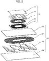
- FIG. 1 and FIG. 2 are a perspective view and an exploded perspective view, respectively, of coil unit 10 at a power receiver end and coil unit 20 at a power transmitter end in accordance with an exemplary embodiment of the present disclosure.
- a contactless power transmission system has coil unit 10 disposed in an electric vehicle, and coil unit 20 disposed at a specified location at which the electric vehicle comes to stop.
- coil unit 10 When the electric vehicle stops at the specified location, coil unit 10 is in a position above coil unit 20. In this situation, coil unit 20 is supplied with high frequency power from a power supply unit (not shown) connected to coil unit 20. This allows electric energy to be transmitted to coil unit 10 in a contactless manner and stored in a vehicle's onboard battery (not shown) connected to coil unit 10.
- coil unit 10 has coil conductor 11 at a power receiver end, coil base 12 at the power receiver end, magnetic shielding member 13 at the power receiver end, and sound insulation member 14 at the power receiver end.
- Coil base 12 retains coil conductor 11.
- Magnetic shielding member 13 is disposed above coil conductor 11.
- Sound insulation member 14 is disposed above magnetic shielding member 13.
- FIG. 3 is a sectional view of coil conductor 11 in accordance with the present exemplary embodiment.
- coil conductor 11 has a plurality of element wires 11a, and insulating member 11b covering a periphery of the plurality of element wires 11a.
- Coil conductor 11 is formed by twisting together the plurality of element wires 11a so as to have diameter R1 in a range from 3 mm to 6 mm, inclusive. Details of coil conductor 11 will be described later.
- FIG. 4 and FIG. 5 are a plan view and a perspective view, respectively, of a coil base in accordance with the present exemplary embodiment.
- coil base 12 has groove 15 formed in a spiral shape for coil conductor 11 to be inserted in groove 15.
- Groove 15 has a plurality of straight portions 15a formed sequentially from an inner periphery to an outer periphery, and a plurality of arc portions 15b formed sequentially from an inner periphery to an outer periphery.
- Each of the plurality of straight portions 15a is formed in parallel to the other.
- the plurality of arc portions 15b are concentric, and each of the plurality of arc portions 15b has a specific radius of curvature.
- the plurality of arc portions 15b are formed so that an innermost arc portion 15b has a radius of curvature equal to or larger than 20 mm.
- a plurality of magnetic shielding member 13 made of ferrite are arranged side by side to cover the upper side of coil conductor 11.
- Sound insulation member 14 made of aluminum is disposed to cover the upper side of coil base 12.
- Coil unit 20 has coil conductor 21 at a power transmitter end, coil base 22 at the power transmitter end, magnetic shielding member 23 at the power transmitter end, and sound insulation member 24 at the power transmitter end.
- Coil base 22 retains coil conductor 21.
- Magnetic shielding member 23 is disposed below coil conductor 21.
- Sound insulation member 24 is disposed below magnetic shielding member 23.
- FIG. 6 is a sectional view of coil conductor 21 in accordance with the present exemplary embodiment.
- coil conductor 21 has a plurality of element wires 21a, and insulating member 21b covering a periphery of the plurality of element wires 21a.
- Coil conductor 21 is formed by twisting together the plurality of element wires 21a so as to have diameter R2 in a range from 3 mm to 6 mm, inclusive. Details of coil conductor 21 will be described later.
- FIG. 7 is a perspective view of coil base 22 in accordance with the present exemplary embodiment.
- coil base 22 has two grooves 25 each of which is formed in a spiral shape and in parallel to the other for coil conductors 21 to be inserted in grooves 25.
- Groove 25 corresponds to a second groove.
- Groove 25 has a plurality of straight portions 25a formed sequentially from an inner periphery to an outer periphery, and a plurality of arc portions 25b formed sequentially from an inner periphery to an outer periphery.
- the plurality of arc portions 25b are concentric, and each of the plurality of arc portions 25b has a specific radius of curvature.
- the plurality of arc portions 25b are formed so that an innermost arc portion 25b has a radius of curvature equal to or larger than 20 mm.
- a plurality of magnetic shielding member 23 made of ferrite are arranged side by side to cover the upper side of coil conductor 21.
- Sound insulation member 24 made of aluminum is disposed to cover the upper side of coil base 22.
- Required minimum diameter R1 of coil conductor 11 and required minimum diameter of coil conductor 21 depend on the supplied high frequency power.
- coil conductor 11 shown in FIG. 3 is supplied with 3.7 kW of high frequency power
- coil conductor 11 is required to have diameter R1 of at least 3 mm.
- Coil conductor 11 in this case may be produced by twisting together 1500 element wires 11a each having a diameter of 0.05 mm to form a wire bundle (not shown), and then coating the outer periphery of the wire bundle with insulating member 11b.
- Insulating member 11b may be made of a resin having an excellent heat-resistance such, for example, as a fluorine resin and may have a thickness of 0.15 mm.
- coil conductor 11 is required to have diameter R1 of at least 5 mm.
- Coil conductor 11 in this case may be produced by twisting together 5000 element wires 11a each having a diameter of 0.05 mm to form a wire bundle (not shown), and then coating the outer periphery of the wire bundle with insulating member 11b.
- coil conductor 21 shown in FIG. 6 is supplied with 3.7 kW of high frequency power, coil conductor 21 is required to have diameter R2 of at least 3 mm.
- Coil conductor 21 in this case may be produced by twisting together 1500 element wires 21a each having a diameter of 0.05 mm to form a wire bundle (not shown), and then coating the outer periphery of the wire bundle with insulating member 21b.
- Insulating member 21b may be made of a resin having an excellent heat-resistance such, for example, as a fluorine resin and may have a thickness of 0.15 mm.
- coil conductor 21 is required to have diameter R2 of at least 5 mm.
- Coil conductor 21 in this case may be produced by twisting together 5000 element wires 21a each having a diameter of 0.05 mm to form a wire bundle (not shown), and then coating the outer periphery of the wire bundle with insulating member 21b.
- the diameter of each element wire 11a, the number of element wires 11a, the diameter of each element wire 21a, the number of element wires 21a, the diameter R1 of coil conductor 11 and the diameter R2 of coil conductor 21 may be appropriately selected depending on the magnitude of the supplied high frequency power.
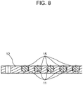
- FIG. 8 is a sectional view of coil base 12 in accordance with the present exemplary embodiment in a state in which coil conductor 11 is inserted in groove 15. As shown in FIG. 8 , coil conductor 11 is inserted in groove 15 formed on coil base 12 to be retained on coil base 12. Groove 15 corresponds to a first groove.
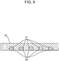
- FIG. 9 is a sectional view of coil base 22 in accordance with the present exemplary embodiment in a state in which coil conductor 21 is inserted in groove 25. As shown in FIG. 9 , coil conductor 21 is inserted in groove 25 formed on coil base 22 to be retained on coil base 22.
- arc portions 15b are formed such that the radius of curvature of the innermost arc portion 15b of groove 15 becomes equal to or larger than 20 mm.
- Arc portions 25b are formed such that, and the radius of curvature of the innermost arc portion 25b of groove 25 becomes equal to or larger than 20 mm.
- the radius of curvature of the innermost arc portion 15b of groove 15 may be made equal to or larger than 30 mm, and the radius of curvature of the innermost arc portion 25b of groove 25 may be made equal to or larger than 30 mm.
- the radius of curvature of the innermost arc portion 15b of groove 15 may be made equal to or larger than 35 mm, and the radius of curvature of the innermost arc portion 25b of groove 25 may be made equal to or larger than 35 mm.
- the radius of curvature of the innermost arc portion 15b and the radius of curvature of the innermost arc portion 25b are each equal to or smaller than 50 mm.
- coil units 10 and 20 can be small-sized. As a result, it is possible to efficiently supply power from coil unit 20 to coil unit 10.
- coil conductor 11 and coil conductor 21 are formed respectively using element wire 11a and element wires 21a each having a diameter of 0.05 mm. Accordingly, coil conductors 11 and 21 can be made lighter in weight.
- the conventional coil unit is produced using a coil conductor which is formed by twisting together a plurality of relatively thick element wires (e.g., 0.1 mm, 0.2 mm or the like). If the diameter of the element wire is made half, the surface area of the element wire becomes one quarter (1/4) and the volume of the element wire becomes one eighth (1/8). Accordingly, it is possible by doubling the number of element wires to prevent increase in volume and weight, while securing the same surface area as that of the conventional stranded wire.
- a coil conductor which is formed by twisting together a plurality of relatively thick element wires (e.g., 0.1 mm, 0.2 mm or the like). If the diameter of the element wire is made half, the surface area of the element wire becomes one quarter (1/4) and the volume of the element wire becomes one eighth (1/8). Accordingly, it is possible by doubling the number of element wires to prevent increase in volume and weight, while securing the same surface area as that of the conventional stranded wire.
- the present exemplary embodiment uses element wires 11a and 21a each having a diameter equal to or smaller than half the diameter of the conventional element wires. Accordingly, it is possible to make coil conductors 11 and 21 lighter in weight compared to the conventional coil conductor.
- coil conductor 11 is formed by the plurality of element wires 11a and insulating member 11b
- coil conductor 21 is formed by the plurality of element wires 21a and insulating member 21b.
- two grooves 25 are formed on coil base 22.
- a single groove 25 may be formed on coil base 22.
- the diameter of each of element wires 11a and 21a is 0.05 mm.
- the diameter of each of element wires 11a and 21a may not be limited to this size, and may be in a range from 0.03 mm to 0.08 mm, inclusive.
- coil unit 10 supplied with 7.7 kW of high frequency power is provided with coil conductor 11 formed by twisting together 5000 element wires 11a each having a diameter of 0.05 mm.
- Coil unit 20 supplied with 7.7 kW of high frequency power is provided with coil conductor 21 formed by twisting together 5000 element wires 21a each having a diameter of 0.05 mm.
- coil conductor 11 may have diameter R1 of at least 5 mm and coil conductor 21 may have diameter R2 of at least 5 mm.
- the number of element wires used may not be limited to 5000.
- the radius of curvature of the innermost arc portion 15b is equal to or larger than 20 mm
- the radius of curvature of the innermost arc portion 25b is equal to or larger than 20 mm.
- the groove may be formed such that the radii of curvature of the arc portions increase in order from the innermost arc portion toward the outermost arc portion or may be formed such that the radii of curvature of the arc portions are constant.
- the radius of curvature of an arc portion 15b having a minimum radius of curvature may be equal to or larger than 20 mm, and the radius of curvature of an arc portion 25b having a minimum radius of curvature may be equal to or larger than 20 mm.
- FIG. 10 is a sectional view of coil base 12 in accordance with the modification example of the present exemplary embodiment in a state in which a coil conductor is inserted in a groove.
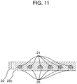
- FIG. 11 is a sectional view of coil base 22 in accordance with the modification example of the present exemplary embodiment in a state in which a coil conductor is inserted in a groove.
- the depth of groove 15 is larger than diameter R1 of coil conductor 11, and the difference between the depth of groove 15 and diameter R1 is in a range from 1.5 mm to 2.0 mm, inclusive.
- the depth of groove 25 is larger than diameter R2 of coil conductor 21, and the difference between the depth of groove 25 and diameter R2 is in a range from 1.5 mm to 2.0 mm, inclusive.
- Rib 15c protruded upward from coil base 12 is formed at the outer periphery of groove 15.
- Rib 25c protruded downward from coil base 22 is formed at the outer periphery of groove 25.
- Ribs 15c and rib 25c correspond to a first rib and a second rib, respectively.
- an upper end of groove 15 is positioned upper than coil conductor 11.
- a lower end of groove 25 is positioned lower than coil conductor 21.
- the upper end of groove 15 and the lower end of groove 25 are each formed in a roundish shape by R-plane chamfering or C-plane chamfering.
- a stress applied to coil conductor 11 at straight portion 15a is different from a stress applied to coil conductor 11 at arc portion 15b. Accordingly, when coil conductor 11 is inserted into groove 15, coil conductor 11 is twisted due to the presence of arc portion 15b.
- a stress applied to coil conductor 21 at straight portion 25a is different from a stress applied to coil conductor 21 at arc portion 25b. Accordingly, when coil conductor 21 is inserted into groove 25, coil conductor 21 is twisted due to the presence of arc portion 25b.
- the depth of groove 15 is larger than diameter R1 of coil conductor 11, and the difference between the depth of groove 15 and diameter R1 is in a range from 1.5 mm to 2.0 mm, inclusive.
- the depth of groove 25 is larger than diameter R2 of coil conductor 21, and the difference between the depth of groove 25 and diameter R2 is in a range from 1.5 mm to 2.0 mm, inclusive.
- coil conductor 11 can be securely placed in groove 15 and is prevented from floating from arc portion 15b.
- coil conductor 21 can be securely placed in groove 25 and is prevented from floating from arc portion 25b. As a result, it is possible to improve reliability of coil units 10 and 20.
- the heights of the ribs 15c and 25c becomes higher, the distance between coil conductor 11 and magnetic shielding member 13 and the distance between coil conductor 21 and magnetic shielding member 23 increase. Therefore, the power transfer efficiency reduces. Accordingly, it is preferable to set the heights of the ribs to be as low as possible while considering the workability and the power transfer efficiency.
- coil conductor 11 After coil conductor 11 has been inserted in coil base 12, coil conductor 11 may be coated with an adhesive or the like to allow coil conductor 11 to be pushed to the bottom of groove 15.
- coil conductor 21 After coil conductor 21 has been inserted in coil base 22, coil conductor 21 may be coated with an adhesive or the like to allow coil conductor 21 to be pushed to the upper part of groove 25.
- FIGS. 12A and 12B are sectional views of stranded wires 17 and 27, respectively, in accordance with the present exemplary embodiment.
- FIGS. 13A and 13B are sectional views of stranded wires 18 and 28, respectively, in accordance with the present exemplary embodiment.
- FIGS. 14A and 14B are sectional views of coil conductors 11 and 21, respectively, in accordance with the present exemplary embodiment.
- the plurality of element wires 11a are twisted together to form each of stranded wires 16.
- a plurality of stranded wires 16 are twisted together to form stranded wire 17.
- a plurality of stranded wires 17 are twisted together to form stranded wire 18.
- a plurality of stranded wires 18 are twisted together to form stranded wire 19.
- the outer periphery of stranded wire 19 is covered with insulating member 11b to form coil conductor 11.
- Stranded wires 16, 17, 18 and 19 respectively correspond to first, second, third and fourth stranded wires at the power receiver end.
- the plurality of element wires 21a are twisted together to form each of stranded wires 26.
- a plurality of stranded wires 26 are twisted together to form stranded wire 27.
- a plurality of stranded wires 27 are twisted together to form stranded wire 28.
- a plurality of stranded wires 28 are twisted together to form stranded wire 29.
- the outer periphery of stranded wire 29 is covered with insulating member 21b to form coil conductor 21.
- Stranded wires 26, 27, 28 and 29 respectively correspond to first, second, third and fourth stranded wires at the power transmitter end.
- Stranded wires 16 and 26 are formed to be smaller in twist pitch than stranded wires 17 and 27, respectively.
- Stranded wires 17 and 27 are formed to be smaller in twist pitch than stranded wires 18 and 28, respectively.
- Stranded wires 18 and 28 are formed to be smaller in twist pitch than stranded wires 19 and 29, respectively.
- stranded wire 16 is formed to have a twist pitch of 40 mm so as to reduce gaps formed when the plurality of element wires 11a are twisted together. Much the same is true for stranded wire 26.
- Stranded wire 17 is formed to have a twist pitch of 50 mm by deforming stranded wires 16 so that the tension applied to element wire 11a at the time of forming stranded wire 17 becomes the same as the tension applied to element wire 11a at the time of forming stranded wire 16. Much the same is true for stranded wire 27.
- Stranded wire 18 is formed to have a twist pitch of 60 mm by deforming stranded wires 17 so that the tension applied to the plurality of element wires 11a at the time of forming stranded wire 18 becomes the same as the tension applied to the plurality of element wires 11a at the time of forming stranded wire 17. Much the same is true for stranded wire 28.
- Stranded wire 19 is formed to have a twist pitch in a range from 65 mm to 75 mm by deforming stranded wires 18 so that the tension applied to the plurality of element wires 11a at the time of forming stranded wire 19 becomes the same as the tension applied to the plurality of element wires 11a at the time of forming stranded wire 18. Much the same is true for stranded wire 29.
- the conventional coil unit uses the coil conductor which is formed by twisting together a plurality of relatively thick element wires (e.g., 0.1 mm, 0.2 mm or the like). If the diameter of the element wire is made half, the surface area of the element wire becomes one quarter (1/4) and the volume of the element wire becomes one eighth (1/8). Accordingly, it is possible by doubling the number of element wires to prevent increase in volume and weight, while securing the same surface area as that of the conventional stranded wire.
- element wires e.g., 0.1 mm, 0.2 mm or the like.
- the present exemplary embodiment uses element wires 11a and 21a each having a diameter equal to or smaller than half the diameter of the conventional element wires. Accordingly, it is possible to make coil conductors 11 and 21 lighter in weight compared to the conventional coil conductors.
- coil conductor 11 is formed by twisting together element wires 11a each having a diameter in a range from 0.03 mm to 0.08 mm, inclusive. According to the present exemplary embodiment, it is possible by twisting together the plurality of element wires 11a plural times to prevent the element wire from being broken due to the tension applied at the time of forming the coil conductor. Much the same is true for coil conductor 21.
- coil conductor 11 and coil conductor 21 lighter in weight by respectively using element wires 11a and element wires 21a which are thinner than the conventional element wires.
- first stranded wire having an approximately circular sectional area by twisting together element wires 11a or 21a at a tension within a range in which the element wires are not broken, while keeping the element wires in close contact with each other.
- stranded wire 17 or 27 it is possible to apply a stress which is larger than the tensile strength of the solid wire to the whole of the plurality of element wires 11a or 21a.
- the twist pitch of stranded wire 17 it is possible by making the twist pitch of stranded wire 17 to be larger than the twist pitch of stranded wire 16 to form a stranded wire which is thinner than a case in which the two twist pitches are the same as each other.
- the twist pitch of the third stranded wire it is possible by making the twist pitch of the third stranded wire to be larger than the twist pitch of the second stranded wire to form a stranded wire which is thinner than a case in which the two twist pitches are the same as each other.
- the twist pitch of the fourth stranded wire it is possible by making the twist pitch of the fourth stranded wire to be larger than the twist pitch of the third stranded wire to form a stranded wire which is thinner than a case in which the two twist pitches are the same as each other. With the above-described configuration, it is possible to make coil conductors 11 and 21 to be thin.
- the twist pitches of stranded wire 16, stranded wire 17, stranded wire 18 and stranded wire 19 are set to be approximately 40 mm, approximately 50 mm, approximately 60 mm and approximately in a range from 65 mm to 75 mm, respectively.
- the twist pitch of each stranded wire may be increased or decreased by approximately 10 mm from these values.
- coil conductors 11 and 21 can be made thin, it is possible to place coil conductor 11 closer to coil conductor 21. As a result, the power transfer efficiency can be improved.
- coil conductors 11 and 21 become thicker, their weights will increase. As a result, the weights of coil units 10 and 20 will increase. Particularly, in a case where coil unit 10 is placed on an electric vehicle, the weight of the electric vehicle will increase, so that the energy saving performances such, for example, as fuel consumption will reduce.
- the present exemplary embodiment it is possible by reducing the weight of coil units 10 and 20 to prevent the weight increase of the electric vehicle. As a result, the energy saving performances can be improved.
- the present disclosure is applicable to contactless power transmission systems that transmit power to an electric vehicle in a contactless manner.
- the coil unit according to the present disclosure is applicable to not only such contactless power transmission systems, but also to other equipment such, for example as an induction heating apparatus.
Landscapes
- Engineering & Computer Science (AREA)
- Power Engineering (AREA)
- Computer Networks & Wireless Communication (AREA)
- Coils Or Transformers For Communication (AREA)
- Coils Of Transformers For General Uses (AREA)
Description
- The present disclosure relates to a coil unit.
- Such a coil unit has heretofore been known that has a retaining member which retains a coil in a groove formed on the retaining member (see, for example, PTL 1).
-
FIG. 15 is an exploded perspective view of the conventional coil unit. As shown inFIG. 15 , the conventional coil unit hasvehicle pad cover 101 having an approximately rectangular depression, andDD coil structure 102 retained invehicle pad cover 101. - Rounded
rectangular depressions 103 are formed in the base of the depression ofvehicle pad cover 101.Spiral groove 104 is formed in eachdepression 103 so as to retainDD coil structure 102. - In the conventional coil unit,
DD coil structure 102 is inserted inspiral groove 104 to be retained invehicle pad cover 101. - PTL 1:
US 2014/327391 A1 - The conventional coil unit still has room for improvement from the view point of improving reliability.
- More specifically, the above prior art document discloses the coil unit having the configuration in which a coil conductor is inserted in the spiral groove formed in the retaining member to be retained in the retaining member. However, the prior art document neither disclose, nor suggest dimensions of the spiral groove.
- Therefore, in a case where the curvature of the spiral groove relative to the diameter of the coil conductor is inappropriate, or more specifically, for example, the curvature of the spiral groove is excessively smaller than the diameter of the coil conductor, the coil conductor would float from the spiral groove, so that the coil unit cannot be maintained in a desired state. As a result, performance and reliability of the coil unit will reduce.
- An object of the present disclosure is to solve the above-described problem of the conventional art to provide a highly reliable coil unit.
- A coil unit according to the present invention as defined in claim 1 comprises: a coil conductor formed of a plurality of element wires; and a coil base having a groove configured to retain the coil conductor. The coil conductor has a diameter in a range from 3 mm to 6 mm, inclusive. The groove has a straight portion, and an arc portion having a radius of curvature of at least 20 mm.
- According to the invention as defined in claim 1, it is possible to prevent separation of the coil conductor from the coil base and break of the coil conductor. As a result, reliability of the coil unit can be improved.
-
-
FIG. 1 is a perspective view of a coil unit at a power receiver end and a coil unit at a power transmitter end in accordance with an exemplary embodiment. -
FIG. 2 is an exploded perspective view of the coil unit at the power receiver end and the coil unit at the power transmitter end in accordance with the exemplary embodiment. -
FIG. 3 is a sectional view of a coil conductor at the power receiver end in accordance with the exemplary embodiment. -
FIG. 4 is a plan view of a coil base at the power receiver end in accordance with the exemplary embodiment. -
FIG. 5 is a perspective view of the coil base at the power receiver end in accordance with the exemplary embodiment. -
FIG. 6 is a sectional view of a coil conductor at the power transmitter end in accordance with the exemplary embodiment. -
FIG. 7 is a perspective view of a coil base at the power transmitter end in accordance with the exemplary embodiment. -
FIG. 8 is a sectional view of the coil base at the power receiver end in accordance with the exemplary embodiment. -
FIG. 9 is a sectional view of the coil base at the power transmitter end in accordance with the exemplary embodiment. -
FIG. 10 is a sectional view of a coil base at the power receiver end in accordance with a modification example of the exemplary embodiment. -
FIG. 11 is a sectional view of a coil base at the power transmitter end in accordance with the modification example of the exemplary embodiment. -
FIG. 12A is a sectional view of a second stranded wire at the power receiver end in accordance with the exemplary embodiment. -
FIG. 12B is a sectional view of a second stranded wire at the power transmitter end in accordance with the exemplary embodiment. -
FIG. 13A is a sectional view of a third stranded wire at the power receiver end in accordance with the exemplary embodiment. -
FIG. 13B is a sectional view of a third stranded wire at the power transmitter end in accordance with the exemplary embodiment. -
FIG. 14A is a sectional view of a coil conductor at the power receiver end in accordance with the exemplary embodiment. -
FIG. 14B is a sectional view of a coil conductor at the power transmitter end in accordance with the exemplary embodiment. -
FIG. 15 is an exploded perspective view of the conventional coil unit. - A coil unit according to the present invention as defined in claim 1 comprises: a coil conductor formed of a plurality of element wires; and a coil base having a groove configured to retain the coil conductor. The coil conductor has a diameter in a range from 3 mm to 6 mm, inclusive. The groove has a straight portion, and an arc portion having a radius of curvature of at least 20 mm.
- In a particular embodiment the coil unit is configured such that a depth of the groove is larger than the diameter of the coil conductor, and a difference between the depth of the groove and the diameter of the coil conductor is in a range from 1.5 mm to 2.0 mm, inclusive.
- In a further embodiment the coil unit is configured such that the coil conductor includes a first stranded wire formed by twisting together a plurality of element wires, a second stranded wire formed by twisting together a plurality of the first stranded wires, and a third stranded wire formed by twisting together a plurality of the second stranded wires.
- In a further embodiment the coil unit is configured such that a twist pitch of the first stranded wire is smaller than a twist pitch of the second stranded wire, and the twist pitch of the second stranded wire is smaller than a twist pitch of the third stranded wire.
- In a further embodiment the coil unit is configured such that the coil conductor includes an insulating member that covers an outer periphery of the plurality of element wires.
- A preferred exemplary embodiment of the present disclosure will hereinafter be described in detail with reference to the drawings. In the following description, like parts or corresponding parts will be indicated by like reference marks, and duplicate description on them will be omitted.
- The exemplary embodiment described hereinafter is an example in which a coil unit in accordance with the present disclosure is applied to a contactless power transmission system for supplying power to an electric vehicle in a contactless manner.
-
FIG. 1 andFIG. 2 are a perspective view and an exploded perspective view, respectively, ofcoil unit 10 at a power receiver end andcoil unit 20 at a power transmitter end in accordance with an exemplary embodiment of the present disclosure. - As shown in
FIGS. 1 and2 , a contactless power transmission system hascoil unit 10 disposed in an electric vehicle, andcoil unit 20 disposed at a specified location at which the electric vehicle comes to stop. - When the electric vehicle stops at the specified location,
coil unit 10 is in a position abovecoil unit 20. In this situation,coil unit 20 is supplied with high frequency power from a power supply unit (not shown) connected tocoil unit 20. This allows electric energy to be transmitted tocoil unit 10 in a contactless manner and stored in a vehicle's onboard battery (not shown) connected tocoil unit 10. - As shown in
FIG. 2 ,coil unit 10 hascoil conductor 11 at a power receiver end,coil base 12 at the power receiver end, magnetic shieldingmember 13 at the power receiver end, andsound insulation member 14 at the power receiver end.Coil base 12 retainscoil conductor 11. Magnetic shieldingmember 13 is disposed abovecoil conductor 11.Sound insulation member 14 is disposed above magnetic shieldingmember 13. -
FIG. 3 is a sectional view ofcoil conductor 11 in accordance with the present exemplary embodiment. As shown inFIG. 3 ,coil conductor 11 has a plurality ofelement wires 11a, and insulatingmember 11b covering a periphery of the plurality ofelement wires 11a.Coil conductor 11 is formed by twisting together the plurality ofelement wires 11a so as to have diameter R1 in a range from 3 mm to 6 mm, inclusive. Details ofcoil conductor 11 will be described later. -
FIG. 4 andFIG. 5 are a plan view and a perspective view, respectively, of a coil base in accordance with the present exemplary embodiment. As shown inFIGS. 4 and5 ,coil base 12 hasgroove 15 formed in a spiral shape forcoil conductor 11 to be inserted ingroove 15. -
Groove 15 has a plurality ofstraight portions 15a formed sequentially from an inner periphery to an outer periphery, and a plurality ofarc portions 15b formed sequentially from an inner periphery to an outer periphery. - Each of the plurality of
straight portions 15a is formed in parallel to the other. The plurality ofarc portions 15b are concentric, and each of the plurality ofarc portions 15b has a specific radius of curvature. The plurality ofarc portions 15b are formed so that aninnermost arc portion 15b has a radius of curvature equal to or larger than 20 mm. - As shown in
FIG. 2 , a plurality of magnetic shieldingmember 13 made of ferrite are arranged side by side to cover the upper side ofcoil conductor 11.Sound insulation member 14 made of aluminum is disposed to cover the upper side ofcoil base 12. -
Coil unit 20 hascoil conductor 21 at a power transmitter end,coil base 22 at the power transmitter end, magnetic shieldingmember 23 at the power transmitter end, andsound insulation member 24 at the power transmitter end.Coil base 22 retainscoil conductor 21. Magnetic shieldingmember 23 is disposed belowcoil conductor 21.Sound insulation member 24 is disposed below magnetic shieldingmember 23. -
FIG. 6 is a sectional view ofcoil conductor 21 in accordance with the present exemplary embodiment. As shown inFIG. 6 ,coil conductor 21 has a plurality ofelement wires 21a, and insulatingmember 21b covering a periphery of the plurality ofelement wires 21a.Coil conductor 21 is formed by twisting together the plurality ofelement wires 21a so as to have diameter R2 in a range from 3 mm to 6 mm, inclusive. Details ofcoil conductor 21 will be described later. -
FIG. 7 is a perspective view ofcoil base 22 in accordance with the present exemplary embodiment. As shown inFIG. 7 ,coil base 22 has twogrooves 25 each of which is formed in a spiral shape and in parallel to the other forcoil conductors 21 to be inserted ingrooves 25.Groove 25 corresponds to a second groove. -
Groove 25 has a plurality ofstraight portions 25a formed sequentially from an inner periphery to an outer periphery, and a plurality ofarc portions 25b formed sequentially from an inner periphery to an outer periphery. - The plurality of
arc portions 25b are concentric, and each of the plurality ofarc portions 25b has a specific radius of curvature. The plurality ofarc portions 25b are formed so that aninnermost arc portion 25b has a radius of curvature equal to or larger than 20 mm. - A plurality of magnetic shielding
member 23 made of ferrite are arranged side by side to cover the upper side ofcoil conductor 21.Sound insulation member 24 made of aluminum is disposed to cover the upper side ofcoil base 22. - Required minimum diameter R1 of
coil conductor 11 and required minimum diameter ofcoil conductor 21 depend on the supplied high frequency power. - Specifically, in a case where
coil conductor 11 shown inFIG. 3 is supplied with 3.7 kW of high frequency power,coil conductor 11 is required to have diameter R1 of at least 3 mm. -
Coil conductor 11 in this case may be produced by twisting together 1500element wires 11a each having a diameter of 0.05 mm to form a wire bundle (not shown), and then coating the outer periphery of the wire bundle with insulatingmember 11b. Insulatingmember 11b may be made of a resin having an excellent heat-resistance such, for example, as a fluorine resin and may have a thickness of 0.15 mm. - In a case where
coil conductor 11 is supplied with 7.7 kW of high frequency power,coil conductor 11 is required to have diameter R1 of at least 5 mm. -
Coil conductor 11 in this case may be produced by twisting together 5000element wires 11a each having a diameter of 0.05 mm to form a wire bundle (not shown), and then coating the outer periphery of the wire bundle with insulatingmember 11b. - In a case where
coil conductor 21 shown inFIG. 6 is supplied with 3.7 kW of high frequency power,coil conductor 21 is required to have diameter R2 of at least 3 mm. -
Coil conductor 21 in this case may be produced by twisting together 1500element wires 21a each having a diameter of 0.05 mm to form a wire bundle (not shown), and then coating the outer periphery of the wire bundle with insulatingmember 21b. Insulatingmember 21b may be made of a resin having an excellent heat-resistance such, for example, as a fluorine resin and may have a thickness of 0.15 mm. - In a case where
coil conductor 21 is supplied with 7.7 kW of high frequency power,coil conductor 21 is required to have diameter R2 of at least 5 mm. -
Coil conductor 21 in this case may be produced by twisting together 5000element wires 21a each having a diameter of 0.05 mm to form a wire bundle (not shown), and then coating the outer periphery of the wire bundle with insulatingmember 21b. - The diameter of each
element wire 11a, the number ofelement wires 11a, the diameter of eachelement wire 21a, the number ofelement wires 21a, the diameter R1 ofcoil conductor 11 and the diameter R2 ofcoil conductor 21 may be appropriately selected depending on the magnitude of the supplied high frequency power. -
FIG. 8 is a sectional view ofcoil base 12 in accordance with the present exemplary embodiment in a state in whichcoil conductor 11 is inserted ingroove 15. As shown inFIG. 8 ,coil conductor 11 is inserted ingroove 15 formed oncoil base 12 to be retained oncoil base 12.Groove 15 corresponds to a first groove. -
FIG. 9 is a sectional view ofcoil base 22 in accordance with the present exemplary embodiment in a state in whichcoil conductor 21 is inserted ingroove 25. As shown inFIG. 9 ,coil conductor 21 is inserted ingroove 25 formed oncoil base 22 to be retained oncoil base 22. - If the radius of curvature of an
arc portion 15b is not properly set relative to diameter R1, it is likely thatcoil conductor 11 would float from thearc portion 15b. If the radius of curvature of anarc portion 25b is not properly set relative to diameter R2, it is likely thatcoil conductor 21 would float from thearc portion 25b. - In the present exemplary embodiment, in a case where each of diameters R1 and R2 is 3 mm,
arc portions 15b are formed such that the radius of curvature of theinnermost arc portion 15b ofgroove 15 becomes equal to or larger than 20 mm.Arc portions 25b are formed such that, and the radius of curvature of theinnermost arc portion 25b ofgroove 25 becomes equal to or larger than 20 mm. - With this configuration, it is possible to prevent occurrence of the above-mentioned defect and to improve reliability of
coil units - In a case where each of diameters R1 and R2 is 5 mm, the radius of curvature of the
innermost arc portion 15b ofgroove 15 may be made equal to or larger than 30 mm, and the radius of curvature of theinnermost arc portion 25b ofgroove 25 may be made equal to or larger than 30 mm. - With this configuration, it is possible to prevent occurrence of the above-mentioned defect and to improve reliability of
coil units - In a case where each of diameters R1 and R2 is 6 mm, the radius of curvature of the
innermost arc portion 15b ofgroove 15 may be made equal to or larger than 35 mm, and the radius of curvature of theinnermost arc portion 25b ofgroove 25 may be made equal to or larger than 35 mm. - With this configuration, it is possible to prevent occurrence of the above-mentioned defect and to improve reliability of
coil units - As the radius of curvature of the
innermost arc portion 15b and the radius of curvature of theinnermost arc portion 25b become larger, the sizes ofcoil units - In the case where
coil units coil unit 10 located outside the region abovecoil unit 20 becomes large when an electric vehicle comes to stop at the specified location. In this case, it is likely that power cannot efficiently be transferred fromcoil unit 20 tocoil unit 10. - Accordingly, it is preferable that the radius of curvature of the
innermost arc portion 15b and the radius of curvature of theinnermost arc portion 25b are each equal to or smaller than 50 mm. - With this configuration,
coil units coil unit 20 tocoil unit 10. - In the present exemplary embodiment,
coil conductor 11 andcoil conductor 21 are formed respectively usingelement wire 11a andelement wires 21a each having a diameter of 0.05 mm. Accordingly,coil conductors - The conventional coil unit is produced using a coil conductor which is formed by twisting together a plurality of relatively thick element wires (e.g., 0.1 mm, 0.2 mm or the like). If the diameter of the element wire is made half, the surface area of the element wire becomes one quarter (1/4) and the volume of the element wire becomes one eighth (1/8). Accordingly, it is possible by doubling the number of element wires to prevent increase in volume and weight, while securing the same surface area as that of the conventional stranded wire.
- The present exemplary embodiment uses
element wires coil conductors - In the present exemplary embodiment,
coil conductor 11 is formed by the plurality ofelement wires 11a and insulatingmember 11b, andcoil conductor 21 is formed by the plurality ofelement wires 21a and insulatingmember 21b. - With this configuration, it is possible to prevent
coil conductors grooves coil units - In the present exemplary embodiment, two
grooves 25 are formed oncoil base 22. However, asingle groove 25 may be formed oncoil base 22. - In the present exemplary embodiment, the diameter of each of
element wires element wires - In the present exemplary embodiment,
coil unit 10 supplied with 7.7 kW of high frequency power is provided withcoil conductor 11 formed by twisting together 5000element wires 11a each having a diameter of 0.05 mm.Coil unit 20 supplied with 7.7 kW of high frequency power is provided withcoil conductor 21 formed by twisting together 5000element wires 21a each having a diameter of 0.05 mm. - However,
coil conductor 11 may have diameter R1 of at least 5 mm andcoil conductor 21 may have diameter R2 of at least 5 mm. Also, the number of element wires used may not be limited to 5000. - In the present exemplary embodiment, the radius of curvature of the
innermost arc portion 15b is equal to or larger than 20 mm, and the radius of curvature of theinnermost arc portion 25b is equal to or larger than 20 mm. - However, the groove may be formed such that the radii of curvature of the arc portions increase in order from the innermost arc portion toward the outermost arc portion or may be formed such that the radii of curvature of the arc portions are constant. The radius of curvature of an
arc portion 15b having a minimum radius of curvature may be equal to or larger than 20 mm, and the radius of curvature of anarc portion 25b having a minimum radius of curvature may be equal to or larger than 20 mm. - Hereinafter, a modification example of the exemplary embodiment of the present disclosure will be described with reference to
FIGS. 10 and11 .FIG. 10 is a sectional view ofcoil base 12 in accordance with the modification example of the present exemplary embodiment in a state in which a coil conductor is inserted in a groove.FIG. 11 is a sectional view ofcoil base 22 in accordance with the modification example of the present exemplary embodiment in a state in which a coil conductor is inserted in a groove. - Referring to
FIG. 10 , the depth ofgroove 15 is larger than diameter R1 ofcoil conductor 11, and the difference between the depth ofgroove 15 and diameter R1 is in a range from 1.5 mm to 2.0 mm, inclusive. Referring toFIG. 11 , the depth ofgroove 25 is larger than diameter R2 ofcoil conductor 21, and the difference between the depth ofgroove 25 and diameter R2 is in a range from 1.5 mm to 2.0 mm, inclusive. -
Rib 15c protruded upward fromcoil base 12 is formed at the outer periphery ofgroove 15.Rib 25c protruded downward fromcoil base 22 is formed at the outer periphery ofgroove 25.Ribs 15c andrib 25c correspond to a first rib and a second rib, respectively. - In a state in which
coil conductor 11 is inserted ingroove 15, an upper end ofgroove 15 is positioned upper thancoil conductor 11. In a state in whichcoil conductor 21 is inserted ingroove 25, a lower end ofgroove 25 is positioned lower thancoil conductor 21. The upper end ofgroove 15 and the lower end ofgroove 25 are each formed in a roundish shape by R-plane chamfering or C-plane chamfering. - A stress applied to
coil conductor 11 atstraight portion 15a is different from a stress applied tocoil conductor 11 atarc portion 15b. Accordingly, whencoil conductor 11 is inserted intogroove 15,coil conductor 11 is twisted due to the presence ofarc portion 15b. - As a result, there is a possibility that residual stresses would be generated in
element wire 11a and insulatingmember 11b, and thatcoil conductor 11 would be deformed to float from the bottom ofgroove 15 atarc portion 15b. - A stress applied to
coil conductor 21 atstraight portion 25a is different from a stress applied tocoil conductor 21 atarc portion 25b. Accordingly, whencoil conductor 21 is inserted intogroove 25,coil conductor 21 is twisted due to the presence ofarc portion 25b. - As a result, there is a possibility that residual stresses would be generated in
element wire 21a and insulatingmember 21b, and thatcoil conductor 21 would be deformed to float from the bottom ofgroove 25 atarc portion 25b. - Considering the above, in the present exemplary embodiment, the depth of
groove 15 is larger than diameter R1 ofcoil conductor 11, and the difference between the depth ofgroove 15 and diameter R1 is in a range from 1.5 mm to 2.0 mm, inclusive. Also, the depth ofgroove 25 is larger than diameter R2 ofcoil conductor 21, and the difference between the depth ofgroove 25 and diameter R2 is in a range from 1.5 mm to 2.0 mm, inclusive. - With this configuration,
coil conductor 11 can be securely placed ingroove 15 and is prevented from floating fromarc portion 15b. Also,coil conductor 21 can be securely placed ingroove 25 and is prevented from floating fromarc portion 25b. As a result, it is possible to improve reliability ofcoil units - As the height of
rib 15c becomes higher, it becomes easier to insertcoil conductor 11 intogroove 15. As the height ofrib 25c becomes higher, it becomes easier to insertcoil conductor 21 intogroove 25. Accordingly, workability is improved. - However, as the heights of the
ribs coil conductor 11 and magnetic shieldingmember 13 and the distance betweencoil conductor 21 and magnetic shieldingmember 23 increase. Therefore, the power transfer efficiency reduces. Accordingly, it is preferable to set the heights of the ribs to be as low as possible while considering the workability and the power transfer efficiency. - This makes it possible to reduce the distance between
coil conductor 11 and magnetic shieldingmember 13, as well as to prevent variations in the distance. Also, it is possible to reduce the distance betweencoil conductor 21 and magnetic shieldingmember 23, as well as to prevent variations in the distance. - After
coil conductor 11 has been inserted incoil base 12,coil conductor 11 may be coated with an adhesive or the like to allowcoil conductor 11 to be pushed to the bottom ofgroove 15. - After
coil conductor 21 has been inserted incoil base 22,coil conductor 21 may be coated with an adhesive or the like to allowcoil conductor 21 to be pushed to the upper part ofgroove 25. - This makes it possible to prevent
coil conductor 11 from floating fromarc portion 15b. Also, it is possible to preventcoil conductor 21 from floating fromarc portion 25b. - The coil conductor in accordance with the exemplary embodiment of the present disclosure will hereinafter be described in detail with reference to
FIGS 12A to 14B .FIGS. 12A and 12B are sectional views of strandedwires FIGS. 13A and 13B are sectional views of strandedwires FIGS. 14A and 14B are sectional views ofcoil conductors - As shown in
FIG. 12A , the plurality ofelement wires 11a are twisted together to form each of strandedwires 16. A plurality of strandedwires 16 are twisted together to form strandedwire 17. As shown inFIG. 13A , a plurality of strandedwires 17 are twisted together to form strandedwire 18. - As shown in
FIG. 14A , a plurality of strandedwires 18 are twisted together to form strandedwire 19. The outer periphery of strandedwire 19 is covered with insulatingmember 11b to formcoil conductor 11. Strandedwires - As shown in
FIG. 12B , the plurality ofelement wires 21a are twisted together to form each of strandedwires 26. A plurality of strandedwires 26 are twisted together to form strandedwire 27. As shown inFIG. 13B , a plurality of strandedwires 27 are twisted together to form strandedwire 28. - As shown in
FIG. 14B , a plurality of strandedwires 28 are twisted together to form strandedwire 29. The outer periphery of strandedwire 29 is covered with insulatingmember 21b to formcoil conductor 21. Strandedwires - Stranded
wires wires wires wires wires wires - Specifically, stranded
wire 16 is formed to have a twist pitch of 40 mm so as to reduce gaps formed when the plurality ofelement wires 11a are twisted together. Much the same is true for strandedwire 26. - Stranded
wire 17 is formed to have a twist pitch of 50 mm by deforming strandedwires 16 so that the tension applied toelement wire 11a at the time of forming strandedwire 17 becomes the same as the tension applied toelement wire 11a at the time of forming strandedwire 16. Much the same is true for strandedwire 27. - Stranded
wire 18 is formed to have a twist pitch of 60 mm by deforming strandedwires 17 so that the tension applied to the plurality ofelement wires 11a at the time of forming strandedwire 18 becomes the same as the tension applied to the plurality ofelement wires 11a at the time of forming strandedwire 17. Much the same is true for strandedwire 28. - Stranded
wire 19 is formed to have a twist pitch in a range from 65 mm to 75 mm by deforming strandedwires 18 so that the tension applied to the plurality ofelement wires 11a at the time of forming strandedwire 19 becomes the same as the tension applied to the plurality ofelement wires 11a at the time of forming strandedwire 18. Much the same is true for strandedwire 29. - The conventional coil unit uses the coil conductor which is formed by twisting together a plurality of relatively thick element wires (e.g., 0.1 mm, 0.2 mm or the like). If the diameter of the element wire is made half, the surface area of the element wire becomes one quarter (1/4) and the volume of the element wire becomes one eighth (1/8). Accordingly, it is possible by doubling the number of element wires to prevent increase in volume and weight, while securing the same surface area as that of the conventional stranded wire.
- The present exemplary embodiment uses
element wires coil conductors - As described above,
coil conductor 11 is formed by twisting togetherelement wires 11a each having a diameter in a range from 0.03 mm to 0.08 mm, inclusive. According to the present exemplary embodiment, it is possible by twisting together the plurality ofelement wires 11a plural times to prevent the element wire from being broken due to the tension applied at the time of forming the coil conductor. Much the same is true forcoil conductor 21. - According to the present exemplary embodiment, it is possible to make
coil conductor 11 andcoil conductor 21 lighter in weight by respectively usingelement wires 11a andelement wires 21a which are thinner than the conventional element wires. - It is possible to prevent
element wires element wires coil units - It is possible to form a first stranded wire having an approximately circular sectional area by twisting together
element wires - At the time of forming stranded
wire element wires - At the time of forming stranded
wire element wires wire 17 to be larger than the twist pitch of strandedwire 16 to form a stranded wire which is thinner than a case in which the two twist pitches are the same as each other. - Similarly, at the time of forming the third stranded wire, it is possible by making the twist pitch of the third stranded wire to be larger than the twist pitch of the second stranded wire to form a stranded wire which is thinner than a case in which the two twist pitches are the same as each other.
- Also, at the time of forming the fourth stranded wire, it is possible by making the twist pitch of the fourth stranded wire to be larger than the twist pitch of the third stranded wire to form a stranded wire which is thinner than a case in which the two twist pitches are the same as each other. With the above-described configuration, it is possible to make
coil conductors - In the present exemplary embodiment, the twist pitches of stranded
wire 16, strandedwire 17, strandedwire 18 and strandedwire 19 are set to be approximately 40 mm, approximately 50 mm, approximately 60 mm and approximately in a range from 65 mm to 75 mm, respectively. However, the twist pitch of each stranded wire may be increased or decreased by approximately 10 mm from these values. - According to the present exemplary embodiment, in each of the cases of forming
coil conductors element wires coil conductors coil units - Since
coil conductors coil conductor 11 closer tocoil conductor 21. As a result, the power transfer efficiency can be improved. - As
coil conductors coil units coil unit 10 is placed on an electric vehicle, the weight of the electric vehicle will increase, so that the energy saving performances such, for example, as fuel consumption will reduce. - According to the present exemplary embodiment, it is possible by reducing the weight of
coil units - The present disclosure is applicable to contactless power transmission systems that transmit power to an electric vehicle in a contactless manner. However, the coil unit according to the present disclosure is applicable to not only such contactless power transmission systems, but also to other equipment such, for example as an induction heating apparatus.
-
- 10, 20
- coil unit
- 11, 21
- coil conductor
- 11a, 21a
- element wire
- 11b, 21b
- insulating member
- 12, 22
- coil base
- 13, 23
- magnetic shielding member
- 14, 24
- sound insulation member
- 15, 25
- groove
- 15a, 25a
- straight portion
- 15b, 25b
- arc portion
- 15c, 25c
- rib
- 16, 26, 17, 27, 18, 28, 19, 29
- stranded wire
Claims (5)
- A coil unit (10, 20) comprising:a coil conductor (11, 21) formed of a plurality of element wires (11a, 21a); anda coil base (12, 22) having a groove (15, 25) configured to retain the coil conductor (11, 21),characterized in that the coil conductor (11, 21) has a diameter in a range from 3 mm to 6 mm, inclusive, andwherein the groove (15, 25) has a straight portion (15a, 25a), and an arc portion (15b, 25b) having a radius of curvature of at least 20 mm.
- The coil unit (10, 20) according to claim 1, wherein a depth of the groove (15, 25) is larger than the diameter of the coil conductor (11, 21), and
wherein a difference between the depth of the groove (15, 25) and the diameter of the coil conductor (11, 21) is in a range from 1.5 mm to 2.0 mm, inclusive. - The coil unit (10, 20) according to claim 1, wherein the coil conductor (11, 21) includes a first stranded wire (16, 26) formed by twisting together the plurality of element wires (11a, 21a), a second stranded wire (17, 27) formed by twisting together a plurality of the first stranded wires (16, 26), and a third stranded wire (18, 28) formed by twisting together a plurality of the second stranded wires (17, 27).
- The coil unit (10, 20) according to claim 3, wherein a twist pitch of the first stranded wire (16, 26) is smaller than a twist pitch of the second stranded wire (17, 27), and the twist pitch of the second stranded wire (17, 27) is smaller than a twist pitch of the third stranded wire (18, 28).
- The coil unit (10, 20) according to claim 1, wherein the coil conductor (11, 21) includes an insulating member (11b, 21b) that covers a periphery of the plurality of element wires (11a, 21a).
Applications Claiming Priority (2)
| Application Number | Priority Date | Filing Date | Title |
|---|---|---|---|
| JP2016235636 | 2016-12-05 | ||
| PCT/JP2017/027428 WO2018105167A1 (en) | 2016-12-05 | 2017-07-28 | Coil unit |
Publications (3)
| Publication Number | Publication Date |
|---|---|
| EP3550579A1 EP3550579A1 (en) | 2019-10-09 |
| EP3550579A4 EP3550579A4 (en) | 2020-01-08 |
| EP3550579B1 true EP3550579B1 (en) | 2021-05-19 |
Family
ID=62492246
Family Applications (1)
| Application Number | Title | Priority Date | Filing Date |
|---|---|---|---|
| EP17879358.4A Active EP3550579B1 (en) | 2016-12-05 | 2017-07-28 | Coil unit |
Country Status (3)
| Country | Link |
|---|---|
| EP (1) | EP3550579B1 (en) |
| JP (1) | JPWO2018105167A1 (en) |
| WO (1) | WO2018105167A1 (en) |
Cited By (1)
| Publication number | Priority date | Publication date | Assignee | Title |
|---|---|---|---|---|
| WO2024175688A3 (en) * | 2023-02-24 | 2024-10-17 | Brusa Elektronik Ag | Main coil assembly for a ground module gpm or for a vehicle module cpm of an inductive charging system for a vehicle |
Families Citing this family (7)
| Publication number | Priority date | Publication date | Assignee | Title |
|---|---|---|---|---|
| JP7373709B2 (en) * | 2019-08-23 | 2023-11-06 | Spiral Tech株式会社 | High frequency coil parts, coil parts for wireless power supply, wireless power supply device, and manufacturing method of frequency coil parts |
| CN110571947B (en) * | 2019-10-17 | 2020-12-04 | 上海瞳鳗智能科技有限公司 | Multifunctional mode circuit and wireless power transfer system |
| WO2022064470A1 (en) * | 2020-09-28 | 2022-03-31 | Molex Cvs Dabendorf Gmbh | Litz wires with ferromagnetic covers, coil topologies, and coils |
| JP7355398B2 (en) * | 2021-03-30 | 2023-10-03 | 株式会社セルコ | Contactless charging coil unit and its manufacturing method |
| JP7773710B2 (en) * | 2021-08-31 | 2025-11-20 | 大日本印刷株式会社 | Coil component and manufacturing method thereof, power transmission device, power receiving device, and power transmission system |
| JP7830918B2 (en) * | 2021-12-15 | 2026-03-17 | 大日本印刷株式会社 | Coil components, power transmission equipment, power receiving equipment, and power transmission systems |
| US20250266715A1 (en) * | 2024-02-15 | 2025-08-21 | Apple Inc. | Wireless Power Transfer Coil with Insulated Conductive Wires |
Family Cites Families (7)
| Publication number | Priority date | Publication date | Assignee | Title |
|---|---|---|---|---|
| JP4057038B2 (en) * | 2006-06-05 | 2008-03-05 | メレアグロス株式会社 | Power transmission method, method for selecting and using coil of power transmission device |
| JP4209437B2 (en) * | 2006-11-10 | 2009-01-14 | 三菱重工業株式会社 | Non-contact power feeding device for mobile body and protection device therefor |
| US9676285B2 (en) * | 2013-05-01 | 2017-06-13 | Qualcomm Incorporated | Vehicle charging pad having reduced thickness |
| JP6221411B2 (en) * | 2013-06-27 | 2017-11-01 | Tdk株式会社 | Coil unit for wireless power transmission |
| DE102013219540A1 (en) * | 2013-09-27 | 2015-04-02 | Siemens Aktiengesellschaft | Charging device for inductive wireless delivery of energy |
| JP6432251B2 (en) * | 2013-11-28 | 2018-12-05 | Tdk株式会社 | Power transmission coil unit and wireless power transmission device |
| JP2017017874A (en) * | 2015-07-01 | 2017-01-19 | 株式会社Ihi | Coil device |
-
2017
- 2017-07-28 WO PCT/JP2017/027428 patent/WO2018105167A1/en not_active Ceased
- 2017-07-28 EP EP17879358.4A patent/EP3550579B1/en active Active
- 2017-07-28 JP JP2018554815A patent/JPWO2018105167A1/en active Pending
Non-Patent Citations (1)
| Title |
|---|
| None * |
Cited By (1)
| Publication number | Priority date | Publication date | Assignee | Title |
|---|---|---|---|---|
| WO2024175688A3 (en) * | 2023-02-24 | 2024-10-17 | Brusa Elektronik Ag | Main coil assembly for a ground module gpm or for a vehicle module cpm of an inductive charging system for a vehicle |
Also Published As
| Publication number | Publication date |
|---|---|
| EP3550579A4 (en) | 2020-01-08 |
| JPWO2018105167A1 (en) | 2019-10-24 |
| WO2018105167A1 (en) | 2018-06-14 |
| EP3550579A1 (en) | 2019-10-09 |
Similar Documents
| Publication | Publication Date | Title |
|---|---|---|
| EP3550579A1 (en) | Coil unit | |
| US20180175645A1 (en) | Wireless charging module having a wireless charging coil and a magnetic sheet | |
| CN104870243B (en) | Device having a winding arrangement and arrangement, in particular a charging station, for contactless transfer of energy to an electric vehicle, having a winding arrangement | |
| EP2669913B1 (en) | Contactless charging module, contactless charging device, and method of manufacturing contactless charging module | |
| MXPA04008860A (en) | Twisted pair cable with cable separator. | |
| US10634517B2 (en) | Resolver stator | |
| CN101399111B (en) | Electrical winding conductor with a rectangular cross section | |
| US11710596B2 (en) | Coil device | |
| CN102171771A (en) | Electric insulated wire and coil | |
| US20210057126A1 (en) | Insulated wire | |
| JP6056100B2 (en) | Spiral coil | |
| JP7355398B2 (en) | Contactless charging coil unit and its manufacturing method | |
| JP4835800B1 (en) | Non-contact charging module and non-contact charging device | |
| JP4962634B1 (en) | Method for manufacturing contactless charging module | |
| WO2017082021A1 (en) | Wire harness | |
| US20190319508A1 (en) | Stator and Electrical Connection Cap thereof | |
| JP6249731B2 (en) | Coil unit and non-contact power transmission device | |
| US11469040B2 (en) | Wireless magnetic charger with solenoids | |
| JP5453898B2 (en) | Flat cable | |
| KR101684429B1 (en) | Transformer for battery charger | |
| US12106875B2 (en) | Wire harness | |
| US10796843B2 (en) | Antenna coil and antenna device | |
| JP4900524B1 (en) | Non-contact charging module and non-contact charging device | |
| JP2009245713A (en) | Shield cable and method of manufacturing the same | |
| JP5874621B2 (en) | High frequency current transmission cable |
Legal Events
| Date | Code | Title | Description |
|---|---|---|---|
| STAA | Information on the status of an ep patent application or granted ep patent |
Free format text: STATUS: THE INTERNATIONAL PUBLICATION HAS BEEN MADE |
|
| PUAI | Public reference made under article 153(3) epc to a published international application that has entered the european phase |
Free format text: ORIGINAL CODE: 0009012 |
|
| STAA | Information on the status of an ep patent application or granted ep patent |
Free format text: STATUS: REQUEST FOR EXAMINATION WAS MADE |
|
| 17P | Request for examination filed |
Effective date: 20190424 |
|
| AK | Designated contracting states |
Kind code of ref document: A1 Designated state(s): AL AT BE BG CH CY CZ DE DK EE ES FI FR GB GR HR HU IE IS IT LI LT LU LV MC MK MT NL NO PL PT RO RS SE SI SK SM TR |
|
| AX | Request for extension of the european patent |
Extension state: BA ME |
|
| A4 | Supplementary search report drawn up and despatched |
Effective date: 20191205 |
|
| RIC1 | Information provided on ipc code assigned before grant |
Ipc: H02J 50/40 20160101ALI20191130BHEP Ipc: H01F 27/30 20060101ALI20191130BHEP Ipc: H02J 50/10 20160101ALI20191130BHEP Ipc: H01F 27/28 20060101ALI20191130BHEP Ipc: H01F 38/14 20060101AFI20191130BHEP |
|
| DAV | Request for validation of the european patent (deleted) | ||
| DAX | Request for extension of the european patent (deleted) | ||
| GRAP | Despatch of communication of intention to grant a patent |
Free format text: ORIGINAL CODE: EPIDOSNIGR1 |
|
| STAA | Information on the status of an ep patent application or granted ep patent |
Free format text: STATUS: GRANT OF PATENT IS INTENDED |
|
| INTG | Intention to grant announced |
Effective date: 20201208 |
|
| GRAS | Grant fee paid |
Free format text: ORIGINAL CODE: EPIDOSNIGR3 |
|
| GRAA | (expected) grant |
Free format text: ORIGINAL CODE: 0009210 |
|
| STAA | Information on the status of an ep patent application or granted ep patent |
Free format text: STATUS: THE PATENT HAS BEEN GRANTED |
|
| AK | Designated contracting states |
Kind code of ref document: B1 Designated state(s): AL AT BE BG CH CY CZ DE DK EE ES FI FR GB GR HR HU IE IS IT LI LT LU LV MC MK MT NL NO PL PT RO RS SE SI SK SM TR |
|
| REG | Reference to a national code |
Ref country code: GB Ref legal event code: FG4D |
|
| REG | Reference to a national code |
Ref country code: CH Ref legal event code: EP |
|
| REG | Reference to a national code |
Ref country code: DE Ref legal event code: R096 Ref document number: 602017039029 Country of ref document: DE |
|
| REG | Reference to a national code |
Ref country code: AT Ref legal event code: REF Ref document number: 1394786 Country of ref document: AT Kind code of ref document: T Effective date: 20210615 |
|
| REG | Reference to a national code |
Ref country code: IE Ref legal event code: FG4D |
|
| REG | Reference to a national code |
Ref country code: LT Ref legal event code: MG9D |
|
| REG | Reference to a national code |
Ref country code: AT Ref legal event code: MK05 Ref document number: 1394786 Country of ref document: AT Kind code of ref document: T Effective date: 20210519 |
|
| REG | Reference to a national code |
Ref country code: NL Ref legal event code: MP Effective date: 20210519 |
|
| PG25 | Lapsed in a contracting state [announced via postgrant information from national office to epo] |
Ref country code: AT Free format text: LAPSE BECAUSE OF FAILURE TO SUBMIT A TRANSLATION OF THE DESCRIPTION OR TO PAY THE FEE WITHIN THE PRESCRIBED TIME-LIMIT Effective date: 20210519 Ref country code: BG Free format text: LAPSE BECAUSE OF FAILURE TO SUBMIT A TRANSLATION OF THE DESCRIPTION OR TO PAY THE FEE WITHIN THE PRESCRIBED TIME-LIMIT Effective date: 20210819 Ref country code: HR Free format text: LAPSE BECAUSE OF FAILURE TO SUBMIT A TRANSLATION OF THE DESCRIPTION OR TO PAY THE FEE WITHIN THE PRESCRIBED TIME-LIMIT Effective date: 20210519 Ref country code: FI Free format text: LAPSE BECAUSE OF FAILURE TO SUBMIT A TRANSLATION OF THE DESCRIPTION OR TO PAY THE FEE WITHIN THE PRESCRIBED TIME-LIMIT Effective date: 20210519 Ref country code: LT Free format text: LAPSE BECAUSE OF FAILURE TO SUBMIT A TRANSLATION OF THE DESCRIPTION OR TO PAY THE FEE WITHIN THE PRESCRIBED TIME-LIMIT Effective date: 20210519 |
|
| PG25 | Lapsed in a contracting state [announced via postgrant information from national office to epo] |
Ref country code: RS Free format text: LAPSE BECAUSE OF FAILURE TO SUBMIT A TRANSLATION OF THE DESCRIPTION OR TO PAY THE FEE WITHIN THE PRESCRIBED TIME-LIMIT Effective date: 20210519 Ref country code: SE Free format text: LAPSE BECAUSE OF FAILURE TO SUBMIT A TRANSLATION OF THE DESCRIPTION OR TO PAY THE FEE WITHIN THE PRESCRIBED TIME-LIMIT Effective date: 20210519 Ref country code: PL Free format text: LAPSE BECAUSE OF FAILURE TO SUBMIT A TRANSLATION OF THE DESCRIPTION OR TO PAY THE FEE WITHIN THE PRESCRIBED TIME-LIMIT Effective date: 20210519 Ref country code: LV Free format text: LAPSE BECAUSE OF FAILURE TO SUBMIT A TRANSLATION OF THE DESCRIPTION OR TO PAY THE FEE WITHIN THE PRESCRIBED TIME-LIMIT Effective date: 20210519 Ref country code: PT Free format text: LAPSE BECAUSE OF FAILURE TO SUBMIT A TRANSLATION OF THE DESCRIPTION OR TO PAY THE FEE WITHIN THE PRESCRIBED TIME-LIMIT Effective date: 20210920 Ref country code: NO Free format text: LAPSE BECAUSE OF FAILURE TO SUBMIT A TRANSLATION OF THE DESCRIPTION OR TO PAY THE FEE WITHIN THE PRESCRIBED TIME-LIMIT Effective date: 20210819 Ref country code: IS Free format text: LAPSE BECAUSE OF FAILURE TO SUBMIT A TRANSLATION OF THE DESCRIPTION OR TO PAY THE FEE WITHIN THE PRESCRIBED TIME-LIMIT Effective date: 20210919 Ref country code: GR Free format text: LAPSE BECAUSE OF FAILURE TO SUBMIT A TRANSLATION OF THE DESCRIPTION OR TO PAY THE FEE WITHIN THE PRESCRIBED TIME-LIMIT Effective date: 20210820 |
|
| PG25 | Lapsed in a contracting state [announced via postgrant information from national office to epo] |
Ref country code: NL Free format text: LAPSE BECAUSE OF FAILURE TO SUBMIT A TRANSLATION OF THE DESCRIPTION OR TO PAY THE FEE WITHIN THE PRESCRIBED TIME-LIMIT Effective date: 20210519 |
|
| PG25 | Lapsed in a contracting state [announced via postgrant information from national office to epo] |
Ref country code: SK Free format text: LAPSE BECAUSE OF FAILURE TO SUBMIT A TRANSLATION OF THE DESCRIPTION OR TO PAY THE FEE WITHIN THE PRESCRIBED TIME-LIMIT Effective date: 20210519 Ref country code: SM Free format text: LAPSE BECAUSE OF FAILURE TO SUBMIT A TRANSLATION OF THE DESCRIPTION OR TO PAY THE FEE WITHIN THE PRESCRIBED TIME-LIMIT Effective date: 20210519 Ref country code: EE Free format text: LAPSE BECAUSE OF FAILURE TO SUBMIT A TRANSLATION OF THE DESCRIPTION OR TO PAY THE FEE WITHIN THE PRESCRIBED TIME-LIMIT Effective date: 20210519 Ref country code: ES Free format text: LAPSE BECAUSE OF FAILURE TO SUBMIT A TRANSLATION OF THE DESCRIPTION OR TO PAY THE FEE WITHIN THE PRESCRIBED TIME-LIMIT Effective date: 20210519 Ref country code: RO Free format text: LAPSE BECAUSE OF FAILURE TO SUBMIT A TRANSLATION OF THE DESCRIPTION OR TO PAY THE FEE WITHIN THE PRESCRIBED TIME-LIMIT Effective date: 20210519 Ref country code: DK Free format text: LAPSE BECAUSE OF FAILURE TO SUBMIT A TRANSLATION OF THE DESCRIPTION OR TO PAY THE FEE WITHIN THE PRESCRIBED TIME-LIMIT Effective date: 20210519 Ref country code: CZ Free format text: LAPSE BECAUSE OF FAILURE TO SUBMIT A TRANSLATION OF THE DESCRIPTION OR TO PAY THE FEE WITHIN THE PRESCRIBED TIME-LIMIT Effective date: 20210519 |
|
| REG | Reference to a national code |
Ref country code: DE Ref legal event code: R097 Ref document number: 602017039029 Country of ref document: DE |
|
| REG | Reference to a national code |
Ref country code: CH Ref legal event code: PL |
|
| PLBE | No opposition filed within time limit |
Free format text: ORIGINAL CODE: 0009261 |
|
| STAA | Information on the status of an ep patent application or granted ep patent |
Free format text: STATUS: NO OPPOSITION FILED WITHIN TIME LIMIT |
|
| PG25 | Lapsed in a contracting state [announced via postgrant information from national office to epo] |
Ref country code: MC Free format text: LAPSE BECAUSE OF FAILURE TO SUBMIT A TRANSLATION OF THE DESCRIPTION OR TO PAY THE FEE WITHIN THE PRESCRIBED TIME-LIMIT Effective date: 20210519 |
|
| REG | Reference to a national code |
Ref country code: BE Ref legal event code: MM Effective date: 20210731 |
|
| 26N | No opposition filed |
Effective date: 20220222 |
|
| GBPC | Gb: european patent ceased through non-payment of renewal fee |
Effective date: 20210819 |
|
| PG25 | Lapsed in a contracting state [announced via postgrant information from national office to epo] |
Ref country code: LI Free format text: LAPSE BECAUSE OF NON-PAYMENT OF DUE FEES Effective date: 20210731 Ref country code: CH Free format text: LAPSE BECAUSE OF NON-PAYMENT OF DUE FEES Effective date: 20210731 |
|
| PG25 | Lapsed in a contracting state [announced via postgrant information from national office to epo] |
Ref country code: IS Free format text: LAPSE BECAUSE OF FAILURE TO SUBMIT A TRANSLATION OF THE DESCRIPTION OR TO PAY THE FEE WITHIN THE PRESCRIBED TIME-LIMIT Effective date: 20210919 Ref country code: LU Free format text: LAPSE BECAUSE OF NON-PAYMENT OF DUE FEES Effective date: 20210728 Ref country code: FR Free format text: LAPSE BECAUSE OF NON-PAYMENT OF DUE FEES Effective date: 20210731 Ref country code: AL Free format text: LAPSE BECAUSE OF FAILURE TO SUBMIT A TRANSLATION OF THE DESCRIPTION OR TO PAY THE FEE WITHIN THE PRESCRIBED TIME-LIMIT Effective date: 20210519 |
|
| PG25 | Lapsed in a contracting state [announced via postgrant information from national office to epo] |
Ref country code: IT Free format text: LAPSE BECAUSE OF FAILURE TO SUBMIT A TRANSLATION OF THE DESCRIPTION OR TO PAY THE FEE WITHIN THE PRESCRIBED TIME-LIMIT Effective date: 20210519 Ref country code: IE Free format text: LAPSE BECAUSE OF NON-PAYMENT OF DUE FEES Effective date: 20210728 Ref country code: GB Free format text: LAPSE BECAUSE OF NON-PAYMENT OF DUE FEES Effective date: 20210819 Ref country code: BE Free format text: LAPSE BECAUSE OF NON-PAYMENT OF DUE FEES Effective date: 20210731 |
|
| PG25 | Lapsed in a contracting state [announced via postgrant information from national office to epo] |
Ref country code: CY Free format text: LAPSE BECAUSE OF FAILURE TO SUBMIT A TRANSLATION OF THE DESCRIPTION OR TO PAY THE FEE WITHIN THE PRESCRIBED TIME-LIMIT Effective date: 20210519 |
|
| PG25 | Lapsed in a contracting state [announced via postgrant information from national office to epo] |
Ref country code: HU Free format text: LAPSE BECAUSE OF FAILURE TO SUBMIT A TRANSLATION OF THE DESCRIPTION OR TO PAY THE FEE WITHIN THE PRESCRIBED TIME-LIMIT; INVALID AB INITIO Effective date: 20170728 |
|
| PG25 | Lapsed in a contracting state [announced via postgrant information from national office to epo] |
Ref country code: MK Free format text: LAPSE BECAUSE OF FAILURE TO SUBMIT A TRANSLATION OF THE DESCRIPTION OR TO PAY THE FEE WITHIN THE PRESCRIBED TIME-LIMIT Effective date: 20210519 |
|
| PG25 | Lapsed in a contracting state [announced via postgrant information from national office to epo] |
Ref country code: MT Free format text: LAPSE BECAUSE OF FAILURE TO SUBMIT A TRANSLATION OF THE DESCRIPTION OR TO PAY THE FEE WITHIN THE PRESCRIBED TIME-LIMIT Effective date: 20210519 |
|
| PGFP | Annual fee paid to national office [announced via postgrant information from national office to epo] |
Ref country code: DE Payment date: 20250722 Year of fee payment: 9 |
|
| PG25 | Lapsed in a contracting state [announced via postgrant information from national office to epo] |
Ref country code: TR Free format text: LAPSE BECAUSE OF FAILURE TO SUBMIT A TRANSLATION OF THE DESCRIPTION OR TO PAY THE FEE WITHIN THE PRESCRIBED TIME-LIMIT Effective date: 20210519 |