EP3550578A1 - Coil core in the form of a ferromagnetic rivet for spiral inductors on printed circuit boards - Google Patents
Coil core in the form of a ferromagnetic rivet for spiral inductors on printed circuit boards Download PDFInfo
- Publication number
- EP3550578A1 EP3550578A1 EP18165616.6A EP18165616A EP3550578A1 EP 3550578 A1 EP3550578 A1 EP 3550578A1 EP 18165616 A EP18165616 A EP 18165616A EP 3550578 A1 EP3550578 A1 EP 3550578A1
- Authority
- EP
- European Patent Office
- Prior art keywords
- rivet
- substrate
- assembly according
- assembly
- conductor
- Prior art date
- Legal status (The legal status is an assumption and is not a legal conclusion. Google has not performed a legal analysis and makes no representation as to the accuracy of the status listed.)
- Granted
Links
Images




Classifications
-
- H—ELECTRICITY
- H01—ELECTRIC ELEMENTS
- H01F—MAGNETS; INDUCTANCES; TRANSFORMERS; SELECTION OF MATERIALS FOR THEIR MAGNETIC PROPERTIES
- H01F27/00—Details of transformers or inductances, in general
- H01F27/24—Magnetic cores
- H01F27/26—Fastening parts of the core together; Fastening or mounting the core on casing or support
- H01F27/266—Fastening or mounting the core on casing or support
-
- H—ELECTRICITY
- H01—ELECTRIC ELEMENTS
- H01F—MAGNETS; INDUCTANCES; TRANSFORMERS; SELECTION OF MATERIALS FOR THEIR MAGNETIC PROPERTIES
- H01F27/00—Details of transformers or inductances, in general
- H01F27/28—Coils; Windings; Conductive connections
- H01F27/2804—Printed windings
-
- H—ELECTRICITY
- H02—GENERATION; CONVERSION OR DISTRIBUTION OF ELECTRIC POWER
- H02J—ELECTRIC POWER NETWORKS; CIRCUIT ARRANGEMENTS OR SYSTEMS FOR SUPPLYING OR DISTRIBUTING ELECTRIC POWER; SYSTEMS FOR STORING ELECTRIC ENERGY
- H02J50/00—Circuit arrangements or systems for wireless supply or distribution of electric power
- H02J50/10—Circuit arrangements or systems for wireless supply or distribution of electric power using inductive coupling
-
- H—ELECTRICITY
- H03—ELECTRONIC CIRCUITRY
- H03H—IMPEDANCE NETWORKS, e.g. RESONANT CIRCUITS; RESONATORS
- H03H7/00—Multiple-port networks comprising only passive electrical elements as network components
- H03H7/38—Impedance-matching networks
-
- H—ELECTRICITY
- H05—ELECTRIC TECHNIQUES NOT OTHERWISE PROVIDED FOR
- H05K—PRINTED CIRCUITS; CASINGS OR CONSTRUCTIONAL DETAILS OF ELECTRIC APPARATUS; MANUFACTURE OF ASSEMBLAGES OF ELECTRICAL COMPONENTS
- H05K1/00—Printed circuits
- H05K1/02—Details
- H05K1/0277—Bendability or stretchability details
-
- H—ELECTRICITY
- H05—ELECTRIC TECHNIQUES NOT OTHERWISE PROVIDED FOR
- H05K—PRINTED CIRCUITS; CASINGS OR CONSTRUCTIONAL DETAILS OF ELECTRIC APPARATUS; MANUFACTURE OF ASSEMBLAGES OF ELECTRICAL COMPONENTS
- H05K1/00—Printed circuits
- H05K1/16—Printed circuits incorporating printed electric components, e.g. printed resistors, capacitors or inductors
- H05K1/165—Printed circuits incorporating printed electric components, e.g. printed resistors, capacitors or inductors incorporating printed inductors
-
- H—ELECTRICITY
- H01—ELECTRIC ELEMENTS
- H01F—MAGNETS; INDUCTANCES; TRANSFORMERS; SELECTION OF MATERIALS FOR THEIR MAGNETIC PROPERTIES
- H01F17/00—Fixed inductances of the signal type
- H01F17/0006—Printed inductances
- H01F2017/006—Printed inductances flexible printed inductors
-
- H—ELECTRICITY
- H01—ELECTRIC ELEMENTS
- H01F—MAGNETS; INDUCTANCES; TRANSFORMERS; SELECTION OF MATERIALS FOR THEIR MAGNETIC PROPERTIES
- H01F38/00—Adaptations of transformers or inductances for specific applications or functions
- H01F38/14—Inductive couplings
Definitions
- Flat spiral inductors are particularly used on flexible conductor boards (e.g. printed circuit boards), particularly for impedance matching or for forming a spiral antenna.
- ferromagnetic and electrically non-conductive materials can be used in the vicinity of the coil as a (e.g. ferrite) core.
- a core In case of cylindrical coils such a core can be designed rather easily and is widely used.
- an assembly comprising
- the present method uses a way to increase the inductance which is simpler than previous methods and allows applying larger amounts of effective ferromagnetic material for increasing inductance.
- a ferromagnetic rivet is used, which can be joined and pressed through the middle of the e.g. flat and spiral coil.
- the use of a ferromagnetic core is highly beneficial.
- an affordable realization of large and flat inductors having a small form factor at the same time can be achieved by way of the present invention.
- the length 1 of the inductor/coil is significantly smaller than its diameter d (1 ⁇ d), so that particularly the ferromagnetic and electrically non-conducting rivet forming the core of the coil generates an inductance that is significantly larger than the inductance of the same coil having an air core instead.
- the conductor of the coil forms a spiral.
- the substrate is a conductor plate, wherein said conductor is formed by at least one conductive path arranged on the substrate.
- the substrate is a printed circuit board and the conductive path is a printed circuit board track.
- the conductive path is arranged on a first side (e.g. upper side) of the substrate, wherein the conductor comprises a further conductive path arranged on a second side (e.g. lower side) of the substrate, which second side faces away from the first side.
- the two conductive paths are electrically connected, e.g. by means of a through-connection such as a VIA (vertical interconnect access).
- the substrate is a flexible substrate.
- the substrate can comprise a thickness in the range from 25 ⁇ m to 300 ⁇ m, particularly 50 ⁇ m.
- the conductive path can have a thickness in the range from 1 ⁇ m to 50 ⁇ m, particularly 3 ⁇ m.
- the substrate can e.g. be formed out of a polyimide, a rigid glass material, a low temperature co-fired ceramic, a high temperature co-fired ceramic or a liquid crystal polymer.
- a polyimide e.g., polyimide
- a rigid glass material e.g., polyethylene
- a low temperature co-fired ceramic e.g., polypropylene
- a high temperature co-fired ceramic e
- the rivet comprises ferromagnetic particles embedded in a carrier material, wherein particularly the carrier material is a plastically deformable material.
- the ferromagnetic material of the rivet or said particles comprise or consist of one of the following materials: AlNiCo, SmCo, Nd 2 Fe 14 B, Ni 80 Fe 20 (so called Permalloy), a NiFeCo alloy (so called Mu-metal), a manganese-zinc ferrite, Mn a Zn (1-a) Fe 2 O 4 , a nickel-zinc ferrite, Ni a Zn (1-a) Fe 2 O 4 .
- a plastically deformable and electrically non-conductive plastic material e.g. polymer
- a liquid crystal polymer that can be plastically deformed by applying heat and thereby joined e.g. with a liquid crystal polymer of the substrate.
- the rivet may comprise at least one part that is not plastically deformed, which part can also be formed out of a ceramic material.
- the rivet is a solid rivet comprising a rivet pin connected to a rivet cap e.g. by a riveting process (e.g. self-piercing riveting).
- the rivet is a semi-tubular rivet (also known in the art as mushroom head rivet or countersunk head rivet) comprising a rivet pin connected to a rivet cap e.g. by a riveting process (e.g. self-piercing riveting).
- the rivet cap is a rivet mandrel used to deform a plastically deformable head of the rivet pin at a hollow end of the rivet pin.
- the rivet is a semi-tubular rivet pin (here no rivet cap is needed) comprising a plastically deformable rivet head at a hollow end of the rivet pin.
- the head is deformed for riveting the rivet to the substrate by means of a separate tool comprising a mandrel for deforming the head of the rivet pin.
- the respective rivet is connected to the substrate by means of self-piercing riveting (or another suitable riveting technique).
- the rivet pin can comprise a diameter in the range from 1 mm to 3 mm, particularly 1.5 mm, and a length in the range from 100 ⁇ m to 300 ⁇ m, particularly 200 ⁇ m.
- the rivet cap can comprise a diameter in the range from 1.5 mm to 3.5 mm, particularly 2 mm, and a thickness in the range from 25 ⁇ m to 75 ⁇ m, particularly 50 ⁇ m.
- the assembly comprises an impedance matching means (e.g. an impedance matching network or an impedance matching circuit) comprising or formed by said electromagnetic coil having the ferromagnetic core.
- an impedance matching means e.g. an impedance matching network or an impedance matching circuit
- the assembly comprises an antenna structure and an integrated circuit, wherein said impedance matching means is configured for impedance matching of the antenna structure with respect to the integrated circuit.
- the antenna structure and/or said integrated circuit is arranged on said substrate of the assembly.
- Such an application of a ferromagnetic rivet according to the present invention is of particular interest concerning an automatic lead recognition using an (e.g. miniature) device arranged on the implantable lead to be recognized, which device comprises the integrated circuit that is configured to contain information about the implantable lead (such as e.g. a serial number of the lead, admission restrictions, etc.).
- an (e.g. miniature) device arranged on the implantable lead to be recognized, which device comprises the integrated circuit that is configured to contain information about the implantable lead (such as e.g. a serial number of the lead, admission restrictions, etc.).
- the integrated circuit is configured to be provided with energy in a wireless fashion by a medical implant that uses said lead, wherein the implant is particularly configured to provide said energy via an antenna of said implant. Further, particularly, the implant is configured to read said information stored in the integrated circuit using e.g. an UHF-RFID technology.
- a lead comprising an assembly according to the present invention (e.g. for impedance matching, see above), particularly for automatic recognition of the lead by an implant using the lead.
- the assembly comprises an antenna formed by the electromagnetic coil or comprising the electromagnetic coil.
- the assembly is configured to use the electromagnetic coil for inductive energy and/or data transmission.
- a medical device comprising an assembly according to the present invention.
- This medical device is preferably implantable.
- the medical device that comprises an assembly according to the present invention is preferably a pacemaker, a defibrillator, a neurostimulator, a cochlear implant or a retina implant.
- the assembly of the invention is particularly suitable for a medical device because of its high mechanical stability. Medical devices are usually implanted into a patient for years and subject to many shocks during their life time. High mechanical stability over a long life time is therefore necessary for such implants. Fixation of a magnetic core to a substrate by a rivet offers a more mechanically stable solution than fixation through brazing or by an adhesive. This is particularly the case if the substrate of the medical device is subject to bending during use. A further advantage of a medical device with an assembly according to the invention is its reduced manufacturing costs. Ferromagnetic cores are usually fixated onto the substrate by use of a solder or an adhesive. In contrast, when using a rivet, no additional material has to be deposited on the substrate in order to fixate the ferromagnetic core of the substrate. The use of a rivet as a ferromagnetic core also allows further miniaturization of the device.
- a further advantage of using a rivet as opposed to solder is that the substrate does not need to be thermally treated in order to fixate the magnetic core onto the substrate, since the riveting process can be performed at ambient temperature. Components that are sensitive to high temperatures can therefore be incorporated without the risk of them being damaged during the soldering process.
- the medical device comprises a housing and the assembly according to the invention is located inside the housing of the medical device.
- a housing can be made of titanium and is configured to be water tight. The advantage of this configuration is that the assembly is not exposed to corrosive bodily fluids.
- the medical device does not comprise a housing or the assembly is located outside of the housing.
- the assembly can be configured to be biocompatible.
- One way of achieving this is to provide an assembly that is entirely embedded in a biocompatible matrix.
- Another possibility is to provide an assembly in which the ferromagnetic particles of the core are embedded into a biocompatible matrix and the substrate is made of a biocompatible material such as LCP.
- the leads do not necessarily have to be made of a biocompatible material. This is possible if the rivet head and cap are configured to entirely enclose the lead between the rivet and the substrate in a water tight manner. As a result, the lead is kept from interacting with the body environment and the assembly is biocompatible.
- the assembly of the invention is configured as a Medical Implant Communication Service (MICS) antenna that is preferably incorporated into the header of the implant.
- MIMS Medical Implant Communication Service
- the assembly according to the invention is MRT-compatible.
- the strong static magnetic field of the MRT leads to saturation of the magnetic flow inside of the ferromagnet.
- the assembly comprising the coil and the ferrogmagnetic core therefore effectively behaves as a coil with an air core during MRT examination. This leads to the resonance frequency of the antenna being significantly raised, which in turn leads to a strong reduction of the unfavorable interaction between the radio frequency pulses inside of the MRT and the implant. Without the saturation effect of the ferromagnetic core, the coil would overheat.
- Fig. 1 shows a schematic illustration of an assembly 1 according to the present invention, comprising an electromagnetic coil 10 comprising a conductor 11, and a substrate (not shown, see below) on which the conductor 11 is arranged.
- the coil 10 comprises a core 12, wherein said conductor 10 extends along or around the core 12, and wherein the core 12 is formed by a ferromagnetic rivet 12 fastened to the substrate.
- the conductor 11 of the coil 10 forms a spiral, as indicated in the top view in the upper part of Fig. 1
- the substrate 20 can be a flexible conductor plate formed e.g. out of polyimide (PI) or a liquid crystal polymer (LCP) and may comprise a thickness T of 50 ⁇ m.
- the conductor 11 can comprise or can be formed by a conductive path 11a in form of a gold coating of the substrate 20, wherein the conductive path 11a may have a thickness T' of e.g. 3 ⁇ m and may form on a first side 20a of the substrate 20 a spiral having two windings, wherein the conductive path 11a can have a width W of e.g. 50 ⁇ m, and a conductive path distance D" of e.g.
- the conductor 11 is passed via a through-connection (e.g. VIA) to the other second side 20b of the substrate 20, where the conductor 11 may also comprise a conductive path 11b in form of a spiral (i.e. as described above).
- a through-connection e.g. VIA
- the coil 10 comprises a core 12 in the form of a ferromagnetic solid rivet 12 comprising a rivet pin 121 having a diameter B of e.g. 1.5 mm, and a length L of e.g. 200 ⁇ m as well as a rivet cap 122 having a diameter A of e.g. 2 mm and a thickness T" of e.g. 100 ⁇ m.
- the rivet pin and cap 121, 122 is connected to the substrate 20 in a form-fitting manner by means of self-piercing riveting such that the rivet pin 121 extends through the substrate 20.
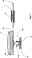
- the riveting process is illustrated for a solid rivet 12 in Fig. 2 .
- the rivet cap 122 is initially arranged on the first side 20a of the substrate 20 and the rivet pin 121 is arranged on the second side 20b of the substrate 20 as indicated on the left-hand side of Fig. 2 (of course, the position of the pin 121 and the cap 122 can also be interchanged).
- the rivet pin 121 comprises a plastically deformable head 121a to be joined to the cap 122.
- the substrate 20 Upon riveting, the substrate 20 is penetrated by the rivet pin 121 and the head 121a of the rivet pin 121 is deformed and joined to the rivet cap 122 so that the ferromagnetic rivet 12 is fastened to the substrate 20 as shown on the right-hand side of Fig. 2 .
- the substrate 20 can also be provided with a bore for receiving the rivet pin 121.
- the inductor 10 can e.g. be part of an impedance matching network for impedance matching of an antenna structure with respect to an integrated circuit (IC), e.g. as described above.
- the coil 10 may also be used as an antenna or alternative for inductive transport of energy and/or data.
- the ferromagnetic rivet 12 forming the coil core 12 can be also formed as a semi-tubular rivet 12, comprising a rivet pin 121 and a rivet cap 122.
- the rivet cap 122 is initially arranged on the first side 20a of the substrate 20 and the rivet pin 121 is arranged on the second side 20b of the substrate 20 as indicated on the left-hand side of Fig. 3 (of course, the position of the pin 121 and the cap 122 can also be interchanged).
- the rivet pin 121 comprises a plastically deformable head 121a at a hollow end 121b of the pin 121 that shall be joined to the cap 122.
- the substrate 20 Upon riveting, the substrate 20 is penetrated by the rivet pin 121 and the head 121a of the rivet pin 121 is deformed and joined to the rivet cap 122 so that the ferromagnetic rivet 12 is fastened to the substrate 20 as shown on the right-hand side of Fig. 3 .
- the substrate 20 can also be provided with a bore for receiving the rivet pin 121.
- a rivet 12 as shown in Fig. 4 can be used as ferromagnetic coil core 12 of the coil 10 of the assembly 1.
- the rivet 12 is a semi-tubular rivet pin 12 comprising a plastically deformable rivet head 121a at a hollow end 121b of the semi-tubular rivet pin 12.
- a mandrel 130 for deforming the pin 12 is arranged on the first side 20a of the substrate 20 and the rivet pin 12 is arranged on the second side 20b of the substrate 20 as indicated on the left-hand side of Fig. 4 (of course, the position of the pin 12 and the mandrel 130 can also be interchanged).
- the rivet pin 12 comprises a plastically deformable head 121a at a hollow end 121b of the pin 12 that shall be deformed to fasten the rivet 12 to the substrate 20.
- the substrate 20 Upon riveting, the substrate 20 is penetrated by the rivet pin 12 and the head 121a of the rivet pin 12 is deformed by the mandrel 130 to fasten the pin 12 to the substrate 20 as shown on the right-hand side of Fig. 4 . Also here, in case a more rigid substrate 20 is used, the substrate 20 can also be provided with a bore for receiving the rivet pin 12.
- the respective ferromagnetic rivet 12 can comprise e.g. the following materials (e.g. in the form of particles 12a): AINiCo, SmCo, Nd 2 Fe 14 B, Ni 80 Fe 20 ("Permalloy"), or NiFeCo alloys ("Mu-metal"), manganese-zinc ferrites (MnZn), e.g. comprising the composition Mn a Zn (1-a) Fe 2 O 4 und nickel-zinc ferrites (NiZn), e.g. comprising the composition Ni a Zn (1-a) Fe 2 O 4 .
- the ferromagnetic material may be incorporated into a carrier material 12b of the respective rivet 12 (e.g. of the rivet pin 121 and/or of the rivet cap 122).
- carrier material basically all plastically deformable, electrically non-conductive plastics or polymers can be used, particularly a liquid crystal polymer (LCP), which can be easily deformed thermically and can e.g. be directly bonded to the substrate.
- LCP liquid crystal polymer
- Those parts of the rivet 12 that are not plastically deformed can also be formed out of usual ceramic materials.
- the present invention provides a simple and affordable method to use comparably large amounts of ferromagnetic material as a core for a flat and spiral coil.
- a particular advantage of the present invention can be seen when considering the inductive transport of energy. For this, it is advantageous to use coils having a high Quality factor, since the latter has a significant influence on the efficiency of the energy transport.
- Fig. 6 shows the course of the inductance of the design described above (cf. Fig. 5 ).
- the inductance increases with increasing relative permeability.
- the Quality factor of this inductor is given by the ratio of reactance and resistance and is shown in Fig. 7 .
- a relative permeability of value 6.95 a clear maximum develops, at which the efficiency of the energy transport becomes maximal.
- Fig. 8 shows an assembly 1 with an impedance matching means 30 comprising an electromagnetic coil 10 with a ferromagnetic rivet 12.
- the assembly further comprises an antennae structure 50 and an integrated circuit (IC) 40.
- the impedance matching means 30 is configured for impedance matching of the antenna structure 50 with respect to the integrated circuit 40.
Landscapes
- Engineering & Computer Science (AREA)
- Power Engineering (AREA)
- Microelectronics & Electronic Packaging (AREA)
- Computer Networks & Wireless Communication (AREA)
- Coils Or Transformers For Communication (AREA)
Abstract
Description
- Flat spiral inductors are particularly used on flexible conductor boards (e.g. printed circuit boards), particularly for impedance matching or for forming a spiral antenna.
- In order to increase the inductance of such a flat spiral either the diameter or the number of windings is increased, or - according to a further possibility - ferromagnetic and electrically non-conductive materials can be used in the vicinity of the coil as a (e.g. ferrite) core. In case of cylindrical coils such a core can be designed rather easily and is widely used.
- In case of flat spiral shaped inductors/coils on conductor boards, providing ferromagnetic cores is rather difficult und thus ferromagnetic cores are rarely used with such coils on conductor boards. In the state of the art, doping the substrate material or using a coating of the coil with a ferromagnetic material is predominantly used.
- However, said doping changes the mechanical properties of the substrate material and the possible density of the ferromagnetic material is limited. Furthermore, coating the coil is expensive and the thickness of the coating is limited to a few micrometers depending on the coating process used.
- In this regard it is an objective of the present invention to provide an assembly that is improved regarding the above-stated difficulties.
- This problem is solved by means of an assembly having the features of
claim 1. Particular embodiments are stated in the corresponding sub claims and/or are described below. - According to
claim 1 an assembly is disclosed, comprising - an electromagnetic coil comprising a conductor, and
- a substrate on which the conductor is arranged,
- Thus, the present method uses a way to increase the inductance which is simpler than previous methods and allows applying larger amounts of effective ferromagnetic material for increasing inductance. Particularly, according to the present invention, a ferromagnetic rivet is used, which can be joined and pressed through the middle of the e.g. flat and spiral coil.
- Particularly in case the outer dimensions of the e.g. spiral coil are limited and thus the outer diameter and the number of windings can only be increased to a limited extent, the use of a ferromagnetic core is highly beneficial. Thus, according to the present invention, there is no need to decrease the stability of the substrate material by doping it. Thus, an affordable realization of large and flat inductors having a small form factor at the same time can be achieved by way of the present invention.
- Particularly, according to an embodiment, the
length 1 of the inductor/coil is significantly smaller than its diameter d (1<<d), so that particularly the ferromagnetic and electrically non-conducting rivet forming the core of the coil generates an inductance that is significantly larger than the inductance of the same coil having an air core instead. - Particularly, according to an embodiment of the assembly according to the present invention, the conductor of the coil forms a spiral.
- Particularly, according to an embodiment of the assembly according to the present invention, the substrate is a conductor plate, wherein said conductor is formed by at least one conductive path arranged on the substrate. Particularly, the substrate is a printed circuit board and the conductive path is a printed circuit board track.
- According to a further embodiment of the assembly, the conductive path is arranged on a first side (e.g. upper side) of the substrate, wherein the conductor comprises a further conductive path arranged on a second side (e.g. lower side) of the substrate, which second side faces away from the first side. Particularly, the two conductive paths are electrically connected, e.g. by means of a through-connection such as a VIA (vertical interconnect access).
- Further, according to an embodiment of the assembly according to the present invention, the substrate is a flexible substrate.
- Particularly, in case of very thin flexible substrates that are used to achieve a form factor that is as small as possible, the application of an inductive element integrated into the substrate in the form of a rivet is very reasonable. In such a design, the number of windings of the coil is strongly limited, since a planar design only allows a small number of layers in contrast to a coil made out of a wound wire.
- Furthermore, a large number of windings leads to an unwanted high parasitic capacitance and thus to a reduced resonance frequency of the coil. This is of particular importance in case of higher frequencies. For this reason, the application of a ferromagnetic rivet core is advantageous since it allows increasing the inductance.
- Further, according to an embodiment of the assembly according to the present invention, the substrate can comprise a thickness in the range from 25 µm to 300 µm, particularly 50 µm. The conductive path can have a thickness in the range from 1 µm to 50 µm, particularly 3 µm.
- Further, according to an embodiment of the assembly according to the present invention, the substrate can e.g. be formed out of a polyimide, a rigid glass material, a low temperature co-fired ceramic, a high temperature co-fired ceramic or a liquid crystal polymer. Other possible materials are polyester or polytetrafluorethylene.
- Further, according to an embodiment of the assembly according to the present invention, the rivet comprises ferromagnetic particles embedded in a carrier material, wherein particularly the carrier material is a plastically deformable material.
- Further, according to an embodiment of the assembly according to the present invention, the ferromagnetic material of the rivet or said particles comprise or consist of one of the following materials: AlNiCo, SmCo, Nd2Fe14B, Ni80Fe20 (so called Permalloy), a NiFeCo alloy (so called Mu-metal), a manganese-zinc ferrite, MnaZn(1-a)Fe2O4, a nickel-zinc ferrite, NiaZn(1-a)Fe2O4.
- Particularly, as a carrier material, a plastically deformable and electrically non-conductive plastic material (e.g. polymer) can be used, particularly a liquid crystal polymer, that can be plastically deformed by applying heat and thereby joined e.g. with a liquid crystal polymer of the substrate. The rivet may comprise at least one part that is not plastically deformed, which part can also be formed out of a ceramic material.
- Further, according to an embodiment of the assembly according to the present invention, the rivet is a solid rivet comprising a rivet pin connected to a rivet cap e.g. by a riveting process (e.g. self-piercing riveting).
- Further, according to an embodiment of the assembly according to the present invention, the rivet is a semi-tubular rivet (also known in the art as mushroom head rivet or countersunk head rivet) comprising a rivet pin connected to a rivet cap e.g. by a riveting process (e.g. self-piercing riveting). Particularly, the rivet cap is a rivet mandrel used to deform a plastically deformable head of the rivet pin at a hollow end of the rivet pin.
- Further, according to an embodiment of the assembly according to the present invention, the rivet is a semi-tubular rivet pin (here no rivet cap is needed) comprising a plastically deformable rivet head at a hollow end of the rivet pin. The head is deformed for riveting the rivet to the substrate by means of a separate tool comprising a mandrel for deforming the head of the rivet pin.
- Further, according to an embodiment of the assembly according to the present invention, the respective rivet is connected to the substrate by means of self-piercing riveting (or another suitable riveting technique).
- Further, according to an embodiment of the assembly according to the present invention, the rivet pin can comprise a diameter in the range from 1 mm to 3 mm, particularly 1.5 mm, and a length in the range from 100 µm to 300 µm, particularly 200 µm. Furthermore, the rivet cap can comprise a diameter in the range from 1.5 mm to 3.5 mm, particularly 2 mm, and a thickness in the range from 25 µm to 75 µm, particularly 50 µm.
- Further, according to an embodiment of the assembly according to the present invention, the assembly comprises an impedance matching means (e.g. an impedance matching network or an impedance matching circuit) comprising or formed by said electromagnetic coil having the ferromagnetic core.
- Further, according to an embodiment of the assembly according to the present invention, the assembly comprises an antenna structure and an integrated circuit, wherein said impedance matching means is configured for impedance matching of the antenna structure with respect to the integrated circuit.
- Further, according to an embodiment of the assembly according to the present invention, the antenna structure and/or said integrated circuit is arranged on said substrate of the assembly.
- Such an application of a ferromagnetic rivet according to the present invention is of particular interest concerning an automatic lead recognition using an (e.g. miniature) device arranged on the implantable lead to be recognized, which device comprises the integrated circuit that is configured to contain information about the implantable lead (such as e.g. a serial number of the lead, admission restrictions, etc.).
- Further, according to an embodiment, the integrated circuit is configured to be provided with energy in a wireless fashion by a medical implant that uses said lead, wherein the implant is particularly configured to provide said energy via an antenna of said implant. Further, particularly, the implant is configured to read said information stored in the integrated circuit using e.g. an UHF-RFID technology.
- According to yet another aspect of the present invention, a lead is disclosed, the lead comprising an assembly according to the present invention (e.g. for impedance matching, see above), particularly for automatic recognition of the lead by an implant using the lead.
- Further, according to an alternative embodiment of the assembly according to the present invention, the assembly comprises an antenna formed by the electromagnetic coil or comprising the electromagnetic coil.
- Further, according to an alternative embodiment of the assembly according to the present invention, the assembly is configured to use the electromagnetic coil for inductive energy and/or data transmission.
- According to yet another aspect of the present invention, a medical device is disclosed, wherein the medical device comprises an assembly according to the present invention. This medical device is preferably implantable.
- The medical device that comprises an assembly according to the present invention is preferably a pacemaker, a defibrillator, a neurostimulator, a cochlear implant or a retina implant.
- The assembly of the invention is particularly suitable for a medical device because of its high mechanical stability. Medical devices are usually implanted into a patient for years and subject to many shocks during their life time. High mechanical stability over a long life time is therefore necessary for such implants. Fixation of a magnetic core to a substrate by a rivet offers a more mechanically stable solution than fixation through brazing or by an adhesive. This is particularly the case if the substrate of the medical device is subject to bending during use. A further advantage of a medical device with an assembly according to the invention is its reduced manufacturing costs. Ferromagnetic cores are usually fixated onto the substrate by use of a solder or an adhesive. In contrast, when using a rivet, no additional material has to be deposited on the substrate in order to fixate the ferromagnetic core of the substrate. The use of a rivet as a ferromagnetic core also allows further miniaturization of the device.
- A further advantage of using a rivet as opposed to solder is that the substrate does not need to be thermally treated in order to fixate the magnetic core onto the substrate, since the riveting process can be performed at ambient temperature. Components that are sensitive to high temperatures can therefore be incorporated without the risk of them being damaged during the soldering process.
- According to one embodiment, the medical device comprises a housing and the assembly according to the invention is located inside the housing of the medical device. Such a housing can be made of titanium and is configured to be water tight. The advantage of this configuration is that the assembly is not exposed to corrosive bodily fluids.
- In an alternative embodiment however, the medical device does not comprise a housing or the assembly is located outside of the housing. This is possible because the assembly can be configured to be biocompatible. One way of achieving this is to provide an assembly that is entirely embedded in a biocompatible matrix. Another possibility is to provide an assembly in which the ferromagnetic particles of the core are embedded into a biocompatible matrix and the substrate is made of a biocompatible material such as LCP. In this embodiment, the leads do not necessarily have to be made of a biocompatible material. This is possible if the rivet head and cap are configured to entirely enclose the lead between the rivet and the substrate in a water tight manner. As a result, the lead is kept from interacting with the body environment and the assembly is biocompatible.
- In one embodiment, the assembly of the invention is configured as a Medical Implant Communication Service (MICS) antenna that is preferably incorporated into the header of the implant. This is particularly advantageous because the assembly according to the invention is MRT-compatible. The strong static magnetic field of the MRT leads to saturation of the magnetic flow inside of the ferromagnet. The assembly comprising the coil and the ferrogmagnetic core therefore effectively behaves as a coil with an air core during MRT examination. This leads to the resonance frequency of the antenna being significantly raised, which in turn leads to a strong reduction of the unfavorable interaction between the radio frequency pulses inside of the MRT and the implant. Without the saturation effect of the ferromagnetic core, the coil would overheat.
- Further features and embodiments of the present invention are described in the following with reference to the Figures, wherein
- Fig. 1
- shows a schematic top view onto an embodiment of an assembly according to the present invention (upper part) as well as a schematic lateral view of the assembly (lower part);
- Fig. 2
- shows a schematic view of a coil core in the form of a ferromagnetic rivet in two different states, namely before riveting a rivet pin to a rivet cap of the rivet (and thereby the rivet to the substrate) on the left-hand side of
Fig. 2 as well as the rivet when it is riveted to the substrate (right-hand side ofFig. 2 ); - Fig. 3
- also shows a rivet according to the present invention in said two states, wherein here the rivet is a semi-tubular rivet comprising a rivet pin and a separate rivet cap that is to be riveted to the rivet pin;
- Fig. 4
- shows a further rivet according to the present invention and said two states wherein here the rivet is a semi-tubular rivet formed by a single rivet pin that is configured to be riveted to the substrate by means of a mandrel;
- Fig. 5
- shows a schematic cross sectional view of yet another embodiment of an assembly according to the present invention;
- Fig. 6
- shows the inductance versus the relative permeability regarding the embodiment shown in
Fig. 5 ; - Fig. 7
- shows the Quality factor versus the relative permeability regarding the embodiments shown in
Fig. 5 ; and - Fig. 8
- shows an assembly according to the invention comprising an antenna structure and an integrated circuit.
-
Fig. 1 shows a schematic illustration of anassembly 1 according to the present invention, comprising anelectromagnetic coil 10 comprising aconductor 11, and a substrate (not shown, see below) on which theconductor 11 is arranged. Thecoil 10 comprises a core 12, wherein saidconductor 10 extends along or around thecore 12, and wherein thecore 12 is formed by aferromagnetic rivet 12 fastened to the substrate. Particularly, theconductor 11 of thecoil 10 forms a spiral, as indicated in the top view in the upper part ofFig. 1 -
Fig. 5 shows a further embodiment of anassembly 1 according to the present invention. Particularly, thesubstrate 20 can be a flexible conductor plate formed e.g. out of polyimide (PI) or a liquid crystal polymer (LCP) and may comprise a thickness T of 50 µm. Theconductor 11 can comprise or can be formed by aconductive path 11a in form of a gold coating of thesubstrate 20, wherein theconductive path 11a may have a thickness T' of e.g. 3 µm and may form on afirst side 20a of thesubstrate 20 a spiral having two windings, wherein theconductive path 11a can have a width W of e.g. 50 µm, and a conductive path distance D" of e.g. 50 µm, an outer diameter D of e.g. 2mm, and an inner diameter D' of e.g. 1.8 mm. In the internal diameter (e.g. center) of thespiral 11a, theconductor 11 is passed via a through-connection (e.g. VIA) to the othersecond side 20b of thesubstrate 20, where theconductor 11 may also comprise aconductive path 11b in form of a spiral (i.e. as described above). - Further, the
coil 10 comprises a core 12 in the form of a ferromagneticsolid rivet 12 comprising arivet pin 121 having a diameter B of e.g. 1.5 mm, and a length L of e.g. 200 µm as well as arivet cap 122 having a diameter A of e.g. 2 mm and a thickness T" of e.g. 100 µm. - The rivet pin and
cap substrate 20 in a form-fitting manner by means of self-piercing riveting such that therivet pin 121 extends through thesubstrate 20. The riveting process is illustrated for asolid rivet 12 inFig. 2 . According thereto, therivet cap 122 is initially arranged on thefirst side 20a of thesubstrate 20 and therivet pin 121 is arranged on thesecond side 20b of thesubstrate 20 as indicated on the left-hand side ofFig. 2 (of course, the position of thepin 121 and thecap 122 can also be interchanged). Therivet pin 121 comprises a plastically deformable head 121a to be joined to thecap 122. Upon riveting, thesubstrate 20 is penetrated by therivet pin 121 and thehead 121a of therivet pin 121 is deformed and joined to therivet cap 122 so that theferromagnetic rivet 12 is fastened to thesubstrate 20 as shown on the right-hand side ofFig. 2 . In case a morerigid substrate 20 is used, thesubstrate 20 can also be provided with a bore for receiving therivet pin 121. - The
inductor 10 can e.g. be part of an impedance matching network for impedance matching of an antenna structure with respect to an integrated circuit (IC), e.g. as described above. Thecoil 10 may also be used as an antenna or alternative for inductive transport of energy and/or data. - Instead of a solid rivet, also
semi-hollow rivets 12 can be used in the above described embodiments. - Particularly, as indicated in
Fig. 3 , theferromagnetic rivet 12 forming thecoil core 12 can be also formed as asemi-tubular rivet 12, comprising arivet pin 121 and arivet cap 122. Also here, therivet cap 122 is initially arranged on thefirst side 20a of thesubstrate 20 and therivet pin 121 is arranged on thesecond side 20b of thesubstrate 20 as indicated on the left-hand side ofFig. 3 (of course, the position of thepin 121 and thecap 122 can also be interchanged). Therivet pin 121 comprises a plasticallydeformable head 121a at ahollow end 121b of thepin 121 that shall be joined to thecap 122. Upon riveting, thesubstrate 20 is penetrated by therivet pin 121 and thehead 121a of therivet pin 121 is deformed and joined to therivet cap 122 so that theferromagnetic rivet 12 is fastened to thesubstrate 20 as shown on the right-hand side ofFig. 3 . Also here, in case a morerigid substrate 20 is used, thesubstrate 20 can also be provided with a bore for receiving therivet pin 121. - According to yet another embodiment, also a
rivet 12 as shown inFig. 4 can be used asferromagnetic coil core 12 of thecoil 10 of theassembly 1. - Here, the
rivet 12 is asemi-tubular rivet pin 12 comprising a plasticallydeformable rivet head 121a at ahollow end 121b of thesemi-tubular rivet pin 12. Again, initially, amandrel 130 for deforming thepin 12 is arranged on thefirst side 20a of thesubstrate 20 and therivet pin 12 is arranged on thesecond side 20b of thesubstrate 20 as indicated on the left-hand side ofFig. 4 (of course, the position of thepin 12 and themandrel 130 can also be interchanged). Therivet pin 12 comprises a plasticallydeformable head 121a at ahollow end 121b of thepin 12 that shall be deformed to fasten therivet 12 to thesubstrate 20. Upon riveting, thesubstrate 20 is penetrated by therivet pin 12 and thehead 121a of therivet pin 12 is deformed by themandrel 130 to fasten thepin 12 to thesubstrate 20 as shown on the right-hand side ofFig. 4 . Also here, in case a morerigid substrate 20 is used, thesubstrate 20 can also be provided with a bore for receiving therivet pin 12. - In the embodiments described above, the respective ferromagnetic rivet 12 (e.g. rivet pin and/or
rivet cap 121, 122) can comprise e.g. the following materials (e.g. in the form ofparticles 12a): AINiCo, SmCo, Nd2Fe14B, Ni80Fe20 ("Permalloy"), or NiFeCo alloys ("Mu-metal"), manganese-zinc ferrites (MnZn), e.g. comprising the composition MnaZn(1-a)Fe2O4 und nickel-zinc ferrites (NiZn), e.g. comprising the composition NiaZn(1-a)Fe2O4. - Furthermore, the ferromagnetic material may be incorporated into a
carrier material 12b of the respective rivet 12 (e.g. of therivet pin 121 and/or of the rivet cap 122). As carrier material basically all plastically deformable, electrically non-conductive plastics or polymers can be used, particularly a liquid crystal polymer (LCP), which can be easily deformed thermically and can e.g. be directly bonded to the substrate. Those parts of therivet 12 that are not plastically deformed can also be formed out of usual ceramic materials. - The present invention provides a simple and affordable method to use comparably large amounts of ferromagnetic material as a core for a flat and spiral coil. A particular advantage of the present invention can be seen when considering the inductive transport of energy. For this, it is advantageous to use coils having a high Quality factor, since the latter has a significant influence on the efficiency of the energy transport.
- For example,
Fig. 6 shows the course of the inductance of the design described above (cf.Fig. 5 ). As expected, the inductance increases with increasing relative permeability. The Quality factor of this inductor is given by the ratio of reactance and resistance and is shown inFig. 7 . Here, in case of a relative permeability of value 6.95 a clear maximum develops, at which the efficiency of the energy transport becomes maximal. -
Fig. 8 shows anassembly 1 with an impedance matching means 30 comprising anelectromagnetic coil 10 with aferromagnetic rivet 12. The assembly further comprises anantennae structure 50 and an integrated circuit (IC) 40. The impedance matching means 30 is configured for impedance matching of theantenna structure 50 with respect to theintegrated circuit 40.
Claims (15)
- An assembly (1), comprising- an electromagnetic coil (10) comprising a conductor (11), and- a substrate (20) on which the conductor (11) is arranged,characterized in that
the coil (10) comprises a core (12), wherein said conductor (10) extends along or around the core (12), and wherein the core (12) is formed by a ferromagnetic rivet fastened to the substrate (20). - The assembly according to claim 1, characterized in that the conductor (11) of the coil (10) forms a spiral.
- The assembly according to claim 1 or 2, characterized in that the substrate (20) is a conductor plate, wherein said conductor (11) is formed by or comprises a conductive path (11a) arranged on the substrate (20).
- The assembly according to claim 3, characterized in that the conductive path (11a) is arranged on a first side (20a) of the substrate (20), wherein the conductor (11) comprises a further conductive path (11b) arranged on a second side (20b) of the substrate (20), which second side (20b) faces away from the first side (20a).
- The assembly according to one of the preceding claims, characterized in that the substrate (20) is a flexible substrate.
- The assembly according to one of the preceding claims, characterized in that said rivet (12) comprises ferromagnetic particles (12a) embedded in a carrier material (12b) and in that the ferromagnetic particles (12a) preferably comprise or consist of one of the following materials: AlNiCo, SmCo, Nd2Fe14B, Ni80Fe20, a NiFeCo alloy, a manganese-zinc ferrite, MnaZn(1-a)Fe2O4, a nickel-zinc ferrite, NiaZn(1-a)Fe2O4.
- The assembly according to claim 6, characterized in that the carrier material (12b) is one of or comprises one of: an electrically non-conductive material, an electrically non-conductive plastic or polymer, a liquid crystal polymer, a ceramic material.
- The assembly according to one of the preceding claims, characterized in that the rivet (12) is a solid rivet comprising a rivet pin (121) and a rivet cap (122).
- The assembly according to one of the claim 1 to 7, characterized in that the rivet (12) is a semi-tubular rivet comprising a rivet pin (121) and a rivet cap (122).
- The assembly according to one of the claim 1 to 7, characterized in that the rivet (12) is a semi-tubular rivet pin (12) comprising a plastically deformable rivet head (121a) at a hollow end (121b) of the semi-tubular rivet pin (12).
- The assembly according to one of the preceding claims, characterized in that the assembly (1) comprises an impedance matching means (30) comprising or formed by said electromagnetic coil (10).
- The assembly according to claim 11, characterized in that the assembly comprises an antenna structure (50) and an integrated circuit (40), wherein said impedance matching means (30) is configured for impedance matching of the antenna structure (50) with respect to the integrated circuit (40).
- The assembly according to one of the claims 1 to 11, characterized in that the assembly (1) comprises an antenna (10) formed by the electromagnetic coil (10) or comprising the electromagnetic coil (10).
- The assembly according to one of the claims 1 to 11, characterized in that the assembly is configured to use the electromagnetic coil (10) for inductive energy and/or data transmission.
- Implantable medical device, preferably a pacemaker, a defibrillator, a neurostimulator, a cochlear implant or a retina implant, characterized in that the device comprises an assembly according to any of the previous claims.
Priority Applications (2)
| Application Number | Priority Date | Filing Date | Title |
|---|---|---|---|
| EP18165616.6A EP3550578B1 (en) | 2018-04-04 | 2018-04-04 | Coil core in the form of a ferromagnetic rivet for spiral inductors on printed circuit boards |
| US16/375,158 US11532422B2 (en) | 2018-04-04 | 2019-04-04 | Coil core in the form of a ferromagnetic rivet for spiral inductors on printed circuit boards |
Applications Claiming Priority (1)
| Application Number | Priority Date | Filing Date | Title |
|---|---|---|---|
| EP18165616.6A EP3550578B1 (en) | 2018-04-04 | 2018-04-04 | Coil core in the form of a ferromagnetic rivet for spiral inductors on printed circuit boards |
Publications (2)
| Publication Number | Publication Date |
|---|---|
| EP3550578A1 true EP3550578A1 (en) | 2019-10-09 |
| EP3550578B1 EP3550578B1 (en) | 2020-12-09 |
Family
ID=61906645
Family Applications (1)
| Application Number | Title | Priority Date | Filing Date |
|---|---|---|---|
| EP18165616.6A Active EP3550578B1 (en) | 2018-04-04 | 2018-04-04 | Coil core in the form of a ferromagnetic rivet for spiral inductors on printed circuit boards |
Country Status (2)
| Country | Link |
|---|---|
| US (1) | US11532422B2 (en) |
| EP (1) | EP3550578B1 (en) |
Cited By (1)
| Publication number | Priority date | Publication date | Assignee | Title |
|---|---|---|---|---|
| CN112216480A (en) * | 2020-09-08 | 2021-01-12 | 杭州铁城信息科技有限公司 | Transformer iron core fixed knot constructs and on-vehicle machine and DC/DC converter that charges thereof |
Families Citing this family (4)
| Publication number | Priority date | Publication date | Assignee | Title |
|---|---|---|---|---|
| CN111786541B (en) | 2019-03-18 | 2021-10-29 | 台达电子工业股份有限公司 | Voltage Regulation Module |
| CN112731996B (en) | 2019-10-28 | 2022-07-15 | 台达电子工业股份有限公司 | Voltage Regulation Module |
| US11735962B2 (en) | 2021-01-29 | 2023-08-22 | Apple Inc. | Methods and circuitry for mitigating saturation in wireless power systems |
| US20230122858A1 (en) * | 2021-10-14 | 2023-04-20 | Compass Technology Company Limited | Method of Embedding a Multi-Layer Lithium Ion Battery on a Flexible Printed Circuit Board |
Citations (2)
| Publication number | Priority date | Publication date | Assignee | Title |
|---|---|---|---|---|
| JPH0590028A (en) * | 1991-09-30 | 1993-04-09 | Toshiba Lighting & Technol Corp | Inductance element and transformer |
| WO2013010455A1 (en) * | 2011-07-19 | 2013-01-24 | 深圳市研通高频技术有限公司 | Variable inductor |
Family Cites Families (3)
| Publication number | Priority date | Publication date | Assignee | Title |
|---|---|---|---|---|
| JP5657133B2 (en) * | 2010-11-23 | 2015-01-21 | カーディアック ペースメイカーズ, インコーポレイテッド | Foldable antenna for implantable medical device |
| US9934895B2 (en) * | 2012-06-29 | 2018-04-03 | Intel Corporation | Spiral near field communication (NFC) coil for consistent coupling with different tags and devices |
| EP3128672B1 (en) * | 2015-08-03 | 2021-01-06 | Advanced Automotive Antennas, S.L.U. | Impedance matching circuit |
-
2018
- 2018-04-04 EP EP18165616.6A patent/EP3550578B1/en active Active
-
2019
- 2019-04-04 US US16/375,158 patent/US11532422B2/en active Active
Patent Citations (2)
| Publication number | Priority date | Publication date | Assignee | Title |
|---|---|---|---|---|
| JPH0590028A (en) * | 1991-09-30 | 1993-04-09 | Toshiba Lighting & Technol Corp | Inductance element and transformer |
| WO2013010455A1 (en) * | 2011-07-19 | 2013-01-24 | 深圳市研通高频技术有限公司 | Variable inductor |
Cited By (1)
| Publication number | Priority date | Publication date | Assignee | Title |
|---|---|---|---|---|
| CN112216480A (en) * | 2020-09-08 | 2021-01-12 | 杭州铁城信息科技有限公司 | Transformer iron core fixed knot constructs and on-vehicle machine and DC/DC converter that charges thereof |
Also Published As
| Publication number | Publication date |
|---|---|
| US20190311839A1 (en) | 2019-10-10 |
| EP3550578B1 (en) | 2020-12-09 |
| US11532422B2 (en) | 2022-12-20 |
Similar Documents
| Publication | Publication Date | Title |
|---|---|---|
| US11532422B2 (en) | Coil core in the form of a ferromagnetic rivet for spiral inductors on printed circuit boards | |
| US9208942B2 (en) | Multi-layer-multi-turn structure for high efficiency wireless communication | |
| US20240348091A1 (en) | Multi-Layer-Multi-Turn Structure For High Efficiency Wireless Communication | |
| US9444213B2 (en) | Method for manufacture of multi-layer wire structure for high efficiency wireless communication | |
| US6115634A (en) | Implantable medical device and method of manufacture | |
| US20130067738A1 (en) | Method for Manufacture of Multi-Layer-Multi-Turn Structure for High Efficiency Wireless Communication | |
| US7503491B2 (en) | RFID chip and antenna with improved range | |
| US20140041218A1 (en) | Method for manufacture of multi-layer wire structure for high efficiency wireless communication | |
| US20080049376A1 (en) | Non-ferromagnetic tank filters in lead wires of active implantable medical devices to enhance mri compatibility | |
| US20070095926A1 (en) | RFID tag with improved range | |
| EP2775564A1 (en) | Multi-layer-multi-turn structure for high efficiency wireless communication | |
| WO2011118379A1 (en) | Rfid system | |
| EP2133827B1 (en) | Radio ic device | |
| US10307603B2 (en) | Hermetic package with inductors and capacitors integrated into ceramic housing | |
| EP2068330A3 (en) | Inductive device including permanent magnet and associated methods | |
| US10511193B2 (en) | Device with a receiving antenna and a related power transfer system | |
| KR101892689B1 (en) | Chip electronic component and board having the same mounted thereon | |
| JP5884888B2 (en) | HF band wireless communication device | |
| EP4440680B1 (en) | Systems and methods for wireless power resonators with open core | |
| EP1970993B1 (en) | RFID chip and antenna with improved range | |
| EP1970840A1 (en) | RFID tag with improved range | |
| US10600550B2 (en) | Coil component | |
| KR102004240B1 (en) | Chip electronic component and board having the same mounted thereon | |
| CN113921248A (en) | Coil component | |
| KR200322720Y1 (en) | Super-thin inductor |
Legal Events
| Date | Code | Title | Description |
|---|---|---|---|
| PUAI | Public reference made under article 153(3) epc to a published international application that has entered the european phase |
Free format text: ORIGINAL CODE: 0009012 |
|
| STAA | Information on the status of an ep patent application or granted ep patent |
Free format text: STATUS: THE APPLICATION HAS BEEN PUBLISHED |
|
| AK | Designated contracting states |
Kind code of ref document: A1 Designated state(s): AL AT BE BG CH CY CZ DE DK EE ES FI FR GB GR HR HU IE IS IT LI LT LU LV MC MK MT NL NO PL PT RO RS SE SI SK SM TR |
|
| AX | Request for extension of the european patent |
Extension state: BA ME |
|
| STAA | Information on the status of an ep patent application or granted ep patent |
Free format text: STATUS: REQUEST FOR EXAMINATION WAS MADE |
|
| 17P | Request for examination filed |
Effective date: 20200302 |
|
| RBV | Designated contracting states (corrected) |
Designated state(s): AL AT BE BG CH CY CZ DE DK EE ES FI FR GB GR HR HU IE IS IT LI LT LU LV MC MK MT NL NO PL PT RO RS SE SI SK SM TR |
|
| GRAP | Despatch of communication of intention to grant a patent |
Free format text: ORIGINAL CODE: EPIDOSNIGR1 |
|
| STAA | Information on the status of an ep patent application or granted ep patent |
Free format text: STATUS: GRANT OF PATENT IS INTENDED |
|
| RIC1 | Information provided on ipc code assigned before grant |
Ipc: H01F 38/14 20060101ALN20200616BHEP Ipc: H01F 17/00 20060101ALN20200616BHEP Ipc: H01F 27/28 20060101ALI20200616BHEP Ipc: H01F 27/26 20060101AFI20200616BHEP |
|
| INTG | Intention to grant announced |
Effective date: 20200706 |
|
| GRAS | Grant fee paid |
Free format text: ORIGINAL CODE: EPIDOSNIGR3 |
|
| GRAA | (expected) grant |
Free format text: ORIGINAL CODE: 0009210 |
|
| STAA | Information on the status of an ep patent application or granted ep patent |
Free format text: STATUS: THE PATENT HAS BEEN GRANTED |
|
| RIN1 | Information on inventor provided before grant (corrected) |
Inventor name: MOSS, CHRISTIAN Inventor name: RUMP, JENS |
|
| AK | Designated contracting states |
Kind code of ref document: B1 Designated state(s): AL AT BE BG CH CY CZ DE DK EE ES FI FR GB GR HR HU IE IS IT LI LT LU LV MC MK MT NL NO PL PT RO RS SE SI SK SM TR |
|
| REG | Reference to a national code |
Ref country code: GB Ref legal event code: FG4D |
|
| REG | Reference to a national code |
Ref country code: AT Ref legal event code: REF Ref document number: 1344238 Country of ref document: AT Kind code of ref document: T Effective date: 20201215 Ref country code: CH Ref legal event code: EP |
|
| REG | Reference to a national code |
Ref country code: DE Ref legal event code: R096 Ref document number: 602018010521 Country of ref document: DE |
|
| REG | Reference to a national code |
Ref country code: IE Ref legal event code: FG4D |
|
| PG25 | Lapsed in a contracting state [announced via postgrant information from national office to epo] |
Ref country code: NO Free format text: LAPSE BECAUSE OF FAILURE TO SUBMIT A TRANSLATION OF THE DESCRIPTION OR TO PAY THE FEE WITHIN THE PRESCRIBED TIME-LIMIT Effective date: 20210309 Ref country code: GR Free format text: LAPSE BECAUSE OF FAILURE TO SUBMIT A TRANSLATION OF THE DESCRIPTION OR TO PAY THE FEE WITHIN THE PRESCRIBED TIME-LIMIT Effective date: 20210310 Ref country code: FI Free format text: LAPSE BECAUSE OF FAILURE TO SUBMIT A TRANSLATION OF THE DESCRIPTION OR TO PAY THE FEE WITHIN THE PRESCRIBED TIME-LIMIT Effective date: 20201209 Ref country code: RS Free format text: LAPSE BECAUSE OF FAILURE TO SUBMIT A TRANSLATION OF THE DESCRIPTION OR TO PAY THE FEE WITHIN THE PRESCRIBED TIME-LIMIT Effective date: 20201209 |
|
| REG | Reference to a national code |
Ref country code: AT Ref legal event code: MK05 Ref document number: 1344238 Country of ref document: AT Kind code of ref document: T Effective date: 20201209 |
|
| PG25 | Lapsed in a contracting state [announced via postgrant information from national office to epo] |
Ref country code: LV Free format text: LAPSE BECAUSE OF FAILURE TO SUBMIT A TRANSLATION OF THE DESCRIPTION OR TO PAY THE FEE WITHIN THE PRESCRIBED TIME-LIMIT Effective date: 20201209 Ref country code: SE Free format text: LAPSE BECAUSE OF FAILURE TO SUBMIT A TRANSLATION OF THE DESCRIPTION OR TO PAY THE FEE WITHIN THE PRESCRIBED TIME-LIMIT Effective date: 20201209 Ref country code: BG Free format text: LAPSE BECAUSE OF FAILURE TO SUBMIT A TRANSLATION OF THE DESCRIPTION OR TO PAY THE FEE WITHIN THE PRESCRIBED TIME-LIMIT Effective date: 20210309 |
|
| REG | Reference to a national code |
Ref country code: NL Ref legal event code: MP Effective date: 20201209 |
|
| PG25 | Lapsed in a contracting state [announced via postgrant information from national office to epo] |
Ref country code: HR Free format text: LAPSE BECAUSE OF FAILURE TO SUBMIT A TRANSLATION OF THE DESCRIPTION OR TO PAY THE FEE WITHIN THE PRESCRIBED TIME-LIMIT Effective date: 20201209 Ref country code: NL Free format text: LAPSE BECAUSE OF FAILURE TO SUBMIT A TRANSLATION OF THE DESCRIPTION OR TO PAY THE FEE WITHIN THE PRESCRIBED TIME-LIMIT Effective date: 20201209 |
|
| REG | Reference to a national code |
Ref country code: LT Ref legal event code: MG9D |
|
| PG25 | Lapsed in a contracting state [announced via postgrant information from national office to epo] |
Ref country code: SM Free format text: LAPSE BECAUSE OF FAILURE TO SUBMIT A TRANSLATION OF THE DESCRIPTION OR TO PAY THE FEE WITHIN THE PRESCRIBED TIME-LIMIT Effective date: 20201209 Ref country code: EE Free format text: LAPSE BECAUSE OF FAILURE TO SUBMIT A TRANSLATION OF THE DESCRIPTION OR TO PAY THE FEE WITHIN THE PRESCRIBED TIME-LIMIT Effective date: 20201209 Ref country code: CZ Free format text: LAPSE BECAUSE OF FAILURE TO SUBMIT A TRANSLATION OF THE DESCRIPTION OR TO PAY THE FEE WITHIN THE PRESCRIBED TIME-LIMIT Effective date: 20201209 Ref country code: PT Free format text: LAPSE BECAUSE OF FAILURE TO SUBMIT A TRANSLATION OF THE DESCRIPTION OR TO PAY THE FEE WITHIN THE PRESCRIBED TIME-LIMIT Effective date: 20210409 Ref country code: RO Free format text: LAPSE BECAUSE OF FAILURE TO SUBMIT A TRANSLATION OF THE DESCRIPTION OR TO PAY THE FEE WITHIN THE PRESCRIBED TIME-LIMIT Effective date: 20201209 Ref country code: SK Free format text: LAPSE BECAUSE OF FAILURE TO SUBMIT A TRANSLATION OF THE DESCRIPTION OR TO PAY THE FEE WITHIN THE PRESCRIBED TIME-LIMIT Effective date: 20201209 Ref country code: LT Free format text: LAPSE BECAUSE OF FAILURE TO SUBMIT A TRANSLATION OF THE DESCRIPTION OR TO PAY THE FEE WITHIN THE PRESCRIBED TIME-LIMIT Effective date: 20201209 |
|
| PG25 | Lapsed in a contracting state [announced via postgrant information from national office to epo] |
Ref country code: PL Free format text: LAPSE BECAUSE OF FAILURE TO SUBMIT A TRANSLATION OF THE DESCRIPTION OR TO PAY THE FEE WITHIN THE PRESCRIBED TIME-LIMIT Effective date: 20201209 Ref country code: AT Free format text: LAPSE BECAUSE OF FAILURE TO SUBMIT A TRANSLATION OF THE DESCRIPTION OR TO PAY THE FEE WITHIN THE PRESCRIBED TIME-LIMIT Effective date: 20201209 |
|
| REG | Reference to a national code |
Ref country code: DE Ref legal event code: R097 Ref document number: 602018010521 Country of ref document: DE |
|
| PG25 | Lapsed in a contracting state [announced via postgrant information from national office to epo] |
Ref country code: IS Free format text: LAPSE BECAUSE OF FAILURE TO SUBMIT A TRANSLATION OF THE DESCRIPTION OR TO PAY THE FEE WITHIN THE PRESCRIBED TIME-LIMIT Effective date: 20210409 |
|
| PLBE | No opposition filed within time limit |
Free format text: ORIGINAL CODE: 0009261 |
|
| STAA | Information on the status of an ep patent application or granted ep patent |
Free format text: STATUS: NO OPPOSITION FILED WITHIN TIME LIMIT |
|
| PG25 | Lapsed in a contracting state [announced via postgrant information from national office to epo] |
Ref country code: AL Free format text: LAPSE BECAUSE OF FAILURE TO SUBMIT A TRANSLATION OF THE DESCRIPTION OR TO PAY THE FEE WITHIN THE PRESCRIBED TIME-LIMIT Effective date: 20201209 Ref country code: IT Free format text: LAPSE BECAUSE OF FAILURE TO SUBMIT A TRANSLATION OF THE DESCRIPTION OR TO PAY THE FEE WITHIN THE PRESCRIBED TIME-LIMIT Effective date: 20201209 |
|
| 26N | No opposition filed |
Effective date: 20210910 |
|
| PG25 | Lapsed in a contracting state [announced via postgrant information from national office to epo] |
Ref country code: MC Free format text: LAPSE BECAUSE OF FAILURE TO SUBMIT A TRANSLATION OF THE DESCRIPTION OR TO PAY THE FEE WITHIN THE PRESCRIBED TIME-LIMIT Effective date: 20201209 Ref country code: SI Free format text: LAPSE BECAUSE OF FAILURE TO SUBMIT A TRANSLATION OF THE DESCRIPTION OR TO PAY THE FEE WITHIN THE PRESCRIBED TIME-LIMIT Effective date: 20201209 Ref country code: DK Free format text: LAPSE BECAUSE OF FAILURE TO SUBMIT A TRANSLATION OF THE DESCRIPTION OR TO PAY THE FEE WITHIN THE PRESCRIBED TIME-LIMIT Effective date: 20201209 |
|
| PG25 | Lapsed in a contracting state [announced via postgrant information from national office to epo] |
Ref country code: LU Free format text: LAPSE BECAUSE OF NON-PAYMENT OF DUE FEES Effective date: 20210404 |
|
| REG | Reference to a national code |
Ref country code: BE Ref legal event code: MM Effective date: 20210430 |
|
| PG25 | Lapsed in a contracting state [announced via postgrant information from national office to epo] |
Ref country code: ES Free format text: LAPSE BECAUSE OF FAILURE TO SUBMIT A TRANSLATION OF THE DESCRIPTION OR TO PAY THE FEE WITHIN THE PRESCRIBED TIME-LIMIT Effective date: 20201209 |
|
| PG25 | Lapsed in a contracting state [announced via postgrant information from national office to epo] |
Ref country code: IS Free format text: LAPSE BECAUSE OF FAILURE TO SUBMIT A TRANSLATION OF THE DESCRIPTION OR TO PAY THE FEE WITHIN THE PRESCRIBED TIME-LIMIT Effective date: 20210409 |
|
| PG25 | Lapsed in a contracting state [announced via postgrant information from national office to epo] |
Ref country code: BE Free format text: LAPSE BECAUSE OF NON-PAYMENT OF DUE FEES Effective date: 20210430 |
|
| PG25 | Lapsed in a contracting state [announced via postgrant information from national office to epo] |
Ref country code: CY Free format text: LAPSE BECAUSE OF FAILURE TO SUBMIT A TRANSLATION OF THE DESCRIPTION OR TO PAY THE FEE WITHIN THE PRESCRIBED TIME-LIMIT Effective date: 20201209 |
|
| P01 | Opt-out of the competence of the unified patent court (upc) registered |
Effective date: 20230612 |
|
| PG25 | Lapsed in a contracting state [announced via postgrant information from national office to epo] |
Ref country code: HU Free format text: LAPSE BECAUSE OF FAILURE TO SUBMIT A TRANSLATION OF THE DESCRIPTION OR TO PAY THE FEE WITHIN THE PRESCRIBED TIME-LIMIT; INVALID AB INITIO Effective date: 20180404 |
|
| PG25 | Lapsed in a contracting state [announced via postgrant information from national office to epo] |
Ref country code: MK Free format text: LAPSE BECAUSE OF FAILURE TO SUBMIT A TRANSLATION OF THE DESCRIPTION OR TO PAY THE FEE WITHIN THE PRESCRIBED TIME-LIMIT Effective date: 20201209 |
|
| PG25 | Lapsed in a contracting state [announced via postgrant information from national office to epo] |
Ref country code: TR Free format text: LAPSE BECAUSE OF FAILURE TO SUBMIT A TRANSLATION OF THE DESCRIPTION OR TO PAY THE FEE WITHIN THE PRESCRIBED TIME-LIMIT Effective date: 20201209 |
|
| PG25 | Lapsed in a contracting state [announced via postgrant information from national office to epo] |
Ref country code: MT Free format text: LAPSE BECAUSE OF FAILURE TO SUBMIT A TRANSLATION OF THE DESCRIPTION OR TO PAY THE FEE WITHIN THE PRESCRIBED TIME-LIMIT Effective date: 20201209 |
|
| PGFP | Annual fee paid to national office [announced via postgrant information from national office to epo] |
Ref country code: GB Payment date: 20260324 Year of fee payment: 9 |
|
| REG | Reference to a national code |
Ref country code: CH Ref legal event code: U11 Free format text: ST27 STATUS EVENT CODE: U-0-0-U10-U11 (AS PROVIDED BY THE NATIONAL OFFICE) Effective date: 20260501 |
|
| PGFP | Annual fee paid to national office [announced via postgrant information from national office to epo] |
Ref country code: DE Payment date: 20260420 Year of fee payment: 9 |
|
| PGFP | Annual fee paid to national office [announced via postgrant information from national office to epo] |
Ref country code: IE Payment date: 20260423 Year of fee payment: 9 Ref country code: CH Payment date: 20260501 Year of fee payment: 9 |
|
| PGFP | Annual fee paid to national office [announced via postgrant information from national office to epo] |
Ref country code: FR Payment date: 20260423 Year of fee payment: 9 |