EP3550309A1 - Kombination pipettenspitzen-aufnahme und greifer - Google Patents
Kombination pipettenspitzen-aufnahme und greifer Download PDFInfo
- Publication number
- EP3550309A1 EP3550309A1 EP18166132.3A EP18166132A EP3550309A1 EP 3550309 A1 EP3550309 A1 EP 3550309A1 EP 18166132 A EP18166132 A EP 18166132A EP 3550309 A1 EP3550309 A1 EP 3550309A1
- Authority
- EP
- European Patent Office
- Prior art keywords
- pipette tip
- adapter
- coupling
- pipetting system
- section
- Prior art date
- Legal status (The legal status is an assumption and is not a legal conclusion. Google has not performed a legal analysis and makes no representation as to the accuracy of the status listed.)
- Granted
Links
Images




Classifications
-
- G—PHYSICS
- G01—MEASURING; TESTING
- G01N—INVESTIGATING OR ANALYSING MATERIALS BY DETERMINING THEIR CHEMICAL OR PHYSICAL PROPERTIES
- G01N35/00—Automatic analysis not limited to methods or materials provided for in any single one of groups G01N1/00 - G01N33/00; Handling materials therefor
- G01N35/10—Devices for transferring samples or any liquids to, in, or from, the analysis apparatus, e.g. suction devices, injection devices
- G01N35/1065—Multiple transfer devices
-
- B—PERFORMING OPERATIONS; TRANSPORTING
- B01—PHYSICAL OR CHEMICAL PROCESSES OR APPARATUS IN GENERAL
- B01L—CHEMICAL OR PHYSICAL LABORATORY APPARATUS FOR GENERAL USE
- B01L3/00—Containers or dishes for laboratory use, e.g. laboratory glassware; Droppers
- B01L3/02—Burettes; Pipettes
- B01L3/021—Pipettes, i.e. with only one conduit for withdrawing and redistributing liquids
-
- B—PERFORMING OPERATIONS; TRANSPORTING
- B01—PHYSICAL OR CHEMICAL PROCESSES OR APPARATUS IN GENERAL
- B01L—CHEMICAL OR PHYSICAL LABORATORY APPARATUS FOR GENERAL USE
- B01L3/00—Containers or dishes for laboratory use, e.g. laboratory glassware; Droppers
- B01L3/02—Burettes; Pipettes
- B01L3/0275—Interchangeable or disposable dispensing tips
-
- B—PERFORMING OPERATIONS; TRANSPORTING
- B01—PHYSICAL OR CHEMICAL PROCESSES OR APPARATUS IN GENERAL
- B01L—CHEMICAL OR PHYSICAL LABORATORY APPARATUS FOR GENERAL USE
- B01L9/00—Supporting devices; Holding devices
-
- B—PERFORMING OPERATIONS; TRANSPORTING
- B25—HAND TOOLS; PORTABLE POWER-DRIVEN TOOLS; MANIPULATORS
- B25J—MANIPULATORS; CHAMBERS PROVIDED WITH MANIPULATION DEVICES
- B25J15/00—Gripping heads and other end effectors
- B25J15/0014—Gripping heads and other end effectors having fork, comb or plate shaped means for engaging the lower surface on a object to be transported
-
- B—PERFORMING OPERATIONS; TRANSPORTING
- B25—HAND TOOLS; PORTABLE POWER-DRIVEN TOOLS; MANIPULATORS
- B25J—MANIPULATORS; CHAMBERS PROVIDED WITH MANIPULATION DEVICES
- B25J15/00—Gripping heads and other end effectors
- B25J15/02—Gripping heads and other end effectors servo-actuated
- B25J15/0253—Gripping heads and other end effectors servo-actuated comprising parallel grippers
-
- B—PERFORMING OPERATIONS; TRANSPORTING
- B25—HAND TOOLS; PORTABLE POWER-DRIVEN TOOLS; MANIPULATORS
- B25J—MANIPULATORS; CHAMBERS PROVIDED WITH MANIPULATION DEVICES
- B25J15/00—Gripping heads and other end effectors
- B25J15/04—Gripping heads and other end effectors with provision for the remote detachment or exchange of the head or parts thereof
- B25J15/0408—Connections means
-
- B—PERFORMING OPERATIONS; TRANSPORTING
- B25—HAND TOOLS; PORTABLE POWER-DRIVEN TOOLS; MANIPULATORS
- B25J—MANIPULATORS; CHAMBERS PROVIDED WITH MANIPULATION DEVICES
- B25J15/00—Gripping heads and other end effectors
- B25J15/06—Gripping heads and other end effectors with vacuum or magnetic holding means
- B25J15/0608—Gripping heads and other end effectors with vacuum or magnetic holding means with magnetic holding means
-
- B—PERFORMING OPERATIONS; TRANSPORTING
- B01—PHYSICAL OR CHEMICAL PROCESSES OR APPARATUS IN GENERAL
- B01L—CHEMICAL OR PHYSICAL LABORATORY APPARATUS FOR GENERAL USE
- B01L2200/00—Solutions for specific problems relating to chemical or physical laboratory apparatus
- B01L2200/02—Adapting objects or devices to another
- B01L2200/025—Align devices or objects to ensure defined positions relative to each other
-
- G—PHYSICS
- G01—MEASURING; TESTING
- G01N—INVESTIGATING OR ANALYSING MATERIALS BY DETERMINING THEIR CHEMICAL OR PHYSICAL PROPERTIES
- G01N35/00—Automatic analysis not limited to methods or materials provided for in any single one of groups G01N1/00 - G01N33/00; Handling materials therefor
- G01N35/10—Devices for transferring samples or any liquids to, in, or from, the analysis apparatus, e.g. suction devices, injection devices
- G01N2035/1027—General features of the devices
- G01N2035/1048—General features of the devices using the transfer device for another function
- G01N2035/1051—General features of the devices using the transfer device for another function for transporting containers, e.g. retained by friction
-
- G—PHYSICS
- G01—MEASURING; TESTING
- G01N—INVESTIGATING OR ANALYSING MATERIALS BY DETERMINING THEIR CHEMICAL OR PHYSICAL PROPERTIES
- G01N35/00—Automatic analysis not limited to methods or materials provided for in any single one of groups G01N1/00 - G01N33/00; Handling materials therefor
- G01N35/10—Devices for transferring samples or any liquids to, in, or from, the analysis apparatus, e.g. suction devices, injection devices
- G01N35/1065—Multiple transfer devices
- G01N35/1067—Multiple transfer devices for transfer to or from containers having different spacing
- G01N2035/1069—Multiple transfer devices for transfer to or from containers having different spacing by adjusting the spacing between multiple probes of a single transferring head
Definitions
- the present invention relates to a pipetting system, in particular with grippers for microplates, deep well plates, sample tubes and other laboratory articles.
- An object of the present invention is to provide a pipetting system in which a gripper can be used together with an inserted pipette tip.
- a pipetting system comprises at least one pipette tip receptacle with a pipette tip arranged therein, which extends along a vertical axis, at least one gripper, which comprises a mechanical coupling which extends along the vertical axis, wherein the gripper with the coupling to the at least a pipette tip receptacle is connected, and at least one gripping element extending from the coupling along the vertical axis, wherein the at least one gripping element comprises at least one substantially vertical portion, wherein the coupling comprises a body having a passageway which extends along the Vertical axis extends over the entire length of the coupling and wherein the pipette tip extends at least partially along the passage channel of the coupling.
- Such an embodiment has the advantage that the pipette tip does not have to be removed in order to mount the gripper. Accordingly, no disposable tips need to be used and disposed of, thereby reducing costs. In addition, no additional holders for pipette tips are needed, whereby the space that would require the holder, otherwise usable.
- the gripping element is arranged laterally on the body of the coupling. This allows a simple and inexpensive installation.
- a first power disc between the body and an axial guide ring is clamped at the upper free end of the clutch, wherein the inner contour of the first power disc in the clamped state projects into the interior of the contour of the passage channel.
- the pipette tip receptacle includes an adapter having a passageway extending along the vertical axis over the entire length of the adapter, the pipette tip extending at least partially along the passageway of the adapter.
- the adapter ensures that the pipette tip is accurately and securely positioned and fixed, and enables accurate and secure positioning and fixation of the gripper on the pipette tip holder.
- the pipette tip extends through the passageway of the adapter and beyond the adapter.
- the adapter may be shorter, the same length or longer than the clutch of the gripper.
- the passageway of the adapter includes a first portion having a first diameter thread, the first portion extending downwardly from the upper end side of the adapter along the vertical axis.
- the adapter comprises a second adjoining the first section Section with a second diameter, wherein the second diameter is smaller than the first diameter.
- the adapter comprises a third section adjoining the second section with a third diameter, wherein the third diameter is smaller than the second diameter, resulting in a circumferential shoulder, on which the pipette tip is arranged.
- the pipette tip comprises a circumferential collar which abuts the peripheral shoulder. The collar of the pipette tip is clamped between the circumferential shoulder and a pipetting tube of a z-axis of a manipulator.
- a driving profile is formed on the outside at the upper free end of the adapter.
- the driver profile may include one or more recesses on the circumference of the adapter. For example, it may be formed ribbed, so that the adapter can be easily screwed by hand to the pipetting tube.
- the entrainment profile may comprise one or more recesses for engagement with a tool, for example a key.
- the adapter comprises a shaft having a cylindrical first portion, a conical second portion, and a cylindrical third portion.
- the through-channel of the coupling comprises corresponding sections, which are substantially congruent with the respective sections of the adapter, or which form identical counterparts to the respective sections of the adapter.
- a circumferential first elevation is provided in the first portion of the adapter, whose outer contour protrudes outwards beyond the contour of the first section, wherein the outer contour of the first elevation lies within the contour of the through-channel of the coupling.
- the circumferential increase causes an increased holding force together with the first power disc and centers the adapter in the passage of the coupling.
- a radially outwardly extending second elevation is provided in the first portion of the adapter, wherein at least one second recess is provided at the upper free end of the coupling which extends radially outwardly from the passageway and wherein the second elevation of the adapter in the second recess of the coupling is receivable, whereby a relative rotation of the gripper with respect to the adapter can be prevented.
- a plurality of elevations may be provided, which may engage in corresponding recesses. The elevations on the adapter and the corresponding recesses on the coupling may be downwardly conically converging along the vertical axis to facilitate retraction and alignment.
- a first seal is provided in the passage of the adapter, in the region of the lower free end of the adapter, which prevents direct contact of the pipette tip with the passageway of the adapter.
- a third seal is arranged on its outside, the outer contour of which protrudes beyond the outer contour of the first section of the adapter.
- the first, second, and third seals are O-rings which ensure compliant and sealing centering of the pipette tip in the adapter.
- a circumferential groove is provided in the first portion of the adapter on its outer side.
- a circumferential fourth groove is provided in a first portion of the passage channel.
- An annular, elastic coupling element is provided, which engages in both grooves.
- the coupling element is a toroidal spring.
- the coupling element may comprise a seal, for example in the form of an at least partially plastic sheath.
- the coupling element can also be completely surrounded by plastic.
- the coupling element may be a clamping ring or a clamping sleeve.
- At least one radial bore is provided in the coupling, which extends radially outward from the fourth groove and in which a pusher is arranged, with which a radially inwardly directed force is exerted on the coupling element.
- a pusher is arranged, with which a radially inwardly directed force is exerted on the coupling element.
- a circumferential second groove is provided in the third portion of the passage channel, in which an annular second seal is arranged, the inner contour protrudes into the interior of the contour of the third portion of the passage channel.
- an O-ring or a lip seal is provided.
- the second seal also centers and seals.
- a circumferential third groove is provided in the first portion of the passageway, in which an annular third seal or in which an annular third seal and a second power disc are arranged, wherein the inner contour of the third seal in the interior of the contour of the first portion the passageway protrudes.
- the third seal may also be an O-ring or a lip seal.
- the second power disc may be made of plastic or metal. With the power disc, a radially inwardly directed force can be exerted on the third seal. This design reduces the stiffness behavior of the third seal when force is applied to the inside of the third seal, as the force plate is more resilient compared to the gripper material in the region of the coupling.
- the body of the coupling comprises a holding device with a side of the Passage channel arranged recess.
- the coupling can be arranged on a holder provided therefor.
- several grippers can be arranged on a holder.
- the recess forms a positive connection with the holder.
- the recess may comprise position holes, which may be arranged distributed over the recess on a regular basis. For example, four position holes can be arranged in a rectangle.
- the body of the clutch comprises magnet holes which extend substantially perpendicular to the recess and in which magnets are arranged at a distance from the recess.
- the magnet holes are arranged on the opposite side of the holding device and ends at a distance from the recess of the holding device.
- the magnets may be cylindrical permanent magnets, which are embedded in the magnet holes.
- the holder may comprise a magnetic element, which together with the magnets of the clutch results in an additional holding force.
- the at least one gripping element comprises at least one substantially horizontal section.
- This section can be formed in one piece or in several parts.
- the at least one horizontal section may comprise one, two or more horizontal tabs integrally formed with or disposed on the vertical section.
- the substantially horizontal portion of the gripping member extends away from the pipette tip.
- the pipette tip is separated by at least one vertical portion of the laboratory article to be gripped and protected accordingly.
- the horizontal portion may be directed against the pipette tip.
- the at least one gripping element comprises at least one further substantially vertical section.
- a damping element is arranged on the vertical section or on the further vertical section.
- the damping element may be, for example, a rubber or foam element; for example in mat or plate form.
- the damping element not only dampens, it also increases the adhesion of the gripping element.
- the at least one gripping element comprises further sections which are arranged between the vertical section and the horizontal section or which are arranged between the vertical section and the further vertical section.
- the further sections may be formed horizontally, vertically, angled or curved. Angled portions are obliquely oriented, i. at an angle that is neither horizontal nor vertical.
- At least one of the further sections comprises a passage opening, which is arranged in the extension of the through-channel.
- the passage opening is in the extension of the Passage channels of the coupling and the adapter arranged. The inserted pipette tip can be freely inserted into the through hole.
- two, more or all portions comprise a separate through-hole or wherein two, more or all portions comprise a common through-hole.
- the pipetting system further comprises a manipulator with which the at least one pipette tip receptacle can be moved along a first horizontal axis, along a second horizontal axis perpendicular to the first horizontal axis, and along a vertical axis perpendicular to the two horizontal axes.
- the pipetting system further comprises at least one holder for at least one gripper.
- the at least one holder can be arranged on a workbench of the system. Several holders can be placed next to each other on the work table.
- the holders may be made of or may comprise a magnetic or magnetizable material.
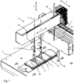
- FIG. 1 shows a partial perspective view of a pipetting system according to the invention.
- the illustrated pipetting system comprises four pipette tip receptacles 4, wherein in each case a pipette tip 40 is arranged in two of the receptacles 4 and wherein in each case a pipette tip 40 and a gripper 1, 5 are arranged in two of the receptacles 4.
- the pipette tip receptacles 4 are arranged on a manipulator 8, with which they are jointly displaceable along a first horizontal axis X and separated from each other along a second horizontal axis Y and along a vertical axis Z are displaceable.
- the manipulator 8 is designed such that the pipette tip receptacles 4 are movable over a work table 9.
- plate holders 7 are arranged for microplates 70.
- One Holder 90 for receiving two grippers is also arranged on the work table 9. If the grippers are in the gripper holder, then a pipette tip receptacle 4 can be moved vertically via the coupling 1 of the corresponding gripper. If the pipette tip holder 4 is inserted into the coupling 1, this is clamped laterally and there is a frictional connection. Alternatively, a positive connection can be realized. The insertion can be done without the removal of the pipette tip 40.
- the coupling 1 can be extended from the laterally arranged pins 90 of the holder 90.
- Two grippers together can remove a microplate 7 from the plate holder 7 and place it precisely elsewhere. If the grippers are no longer needed, they can be re-arranged in the holder 90.
- both are magnetic or magnetizable and at least one of the two elements comprises a permanent magnet.
- like elements are designated by like reference numerals.
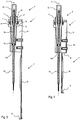
- FIG. 2 shows perspective views of an embodiment of a gripper according to the invention, wherein the FIG. 2A shows the gripper with a coupling 1 and a first gripping element 2, wherein the coupling 1 is arranged on an adapter 3 with a pipette tip 40 inserted therein.
- the FIG. 2B shows the same embodiment of the gripper from one of the first page opposite side, but without adapter and pipette tip.
- the pipette tip 40 protrudes through the entire adapter 3, the entire coupling 1 and a lower end face of the coupling 1.
- a first gripping member 2 is fixed. Specifically, the first gripping element 2 is screwed by screws to the body 10.
- the first gripping element 2 comprises a vertical section 20 and a horizontal section 21.
- the gripping element 2 is fastened to the coupling 1 with the vertical section 20.
- the horizontal portion 21 extends away from the pipette tip 40.
- the gripping element 2 projects beyond the pipette tip 40 downwards.
- the gripping element 2 is made narrow in the upper region close to the coupling and widens towards the horizontal section 21 towards the bottom, resulting in a substantially triangular shape of the vertical section 20.
- the horizontal section 21 comprises two horizontal tabs, which are each arranged in a lateral edge region of the vertical section 20, ie are formed integrally with the vertical section 20 in the lateral corner regions of the triangle.
- the first gripping element 2 is made for example of metal, such as stainless steel or aluminum or plastic, such as PEEK (polyetheretherketone). Between the two tabs 21, a damping element 22 is formed on the vertical portion 20, for example of a foam mat.
- a first power disk 11 is then arranged on the body 10, which is clamped between the body 10 and an axial guide ring 12 is held. In the illustrated embodiment, screws are used to create the clamping action.
- a passageway 100 extends from the upper free end of the coupling, or the axial guide ring 12, along a vertical axis V over the entire length of the coupling 1.
- the first power disk 11 is made of an elastic material, for example of an elastic plastic, such as rubber or silicone. With the power disc, the gripper can be centered on the adapter 3, clamped and aligned. In addition, so that the gap between the clutch 1 and the adapter 3 are sealed.
- the body 10 of the coupling 1 may be made of metal such as stainless steel or aluminum, or it may be made of plastic such as PEEK (polyether ether ketone). On one side of the body 10 of the coupling 1, which is opposite to the attachment side of the first gripping element 2, a holding device 19 is formed.
- the holding device 19 comprises a recess 190, in which position holes 191 are provided. Shown are four position holes 191 which are arranged in a rectangle, wherein two of the holes are arranged in an upper region of the recess 190 and two in a lower region. From the attachment side, magnet holes 192 protrude into the body 10, extend substantially perpendicular to a surface of the recess 190, and terminate inside the body 10 before Reaching the surface of the recess 190. The magnet holes 192 are arranged in a plane which lies between the upper and lower position holes 191 of the holding device 19. In the magnet holes 191 cylindrical permanent magnets 193 are arranged.
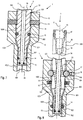
- FIG. 3 shows a sectional view of another embodiment of a gripper according to the invention 1,2 wherein the passageway 100, an adapter 3 is arranged with a pipette tip 40 inserted therein.
- the adapter 3 is arranged on a tubular Z-bar 80, that screwed with this.
- the adapter 3 comprises a passage 34, which extends along the vertical axis V from the upper free end over the entire length of the adapter 3.
- the passageway 34 includes a first portion having a first diameter thread 36, the first portion extending downwardly from the upper end side of the adapter 3 along the vertical axis V. Subsequent to the first section, a second section is formed with a smaller diameter.
- a third section is formed with a smaller diameter, resulting in a circumferential shoulder 35, on which a circumferential collar 41 of the pipette tip 4 is arranged.
- a first seal 13 is provided in the passage 34.
- an O-ring 13 is disposed in a circumferential groove in the shaft body 30 of the adapter. The O-ring 13 centers the pipette tip 40 in the through-channel 34 of the adapter 3 and thus in the through-channel 100 of the coupling 1.
- the adapter 3 comprises at its upper free end a peripheral driving profile 37 to which a tool can be attached to screw the adapter 3 with the thread of the Z-bar 80.
- the adapter 3 comprises on its outer side a circumferential groove 33 which is provided adjacent to the driving profile.
- An elastic coupling element 17 of the coupling 1 engages in the assembled state in the circumferential groove 33 of the adapter 3, whereby a positive and non-positive connection can be realized.
- a gripping element 2 is provided which comprises a vertical section 20 and a horizontal section 21 adjoining thereto, the horizontal section 21 being directed against the pipette tip 40.
- the vertical portion 20 extends substantially beyond the lower tip of the pipette tip 40.
- the vertical distance between the pipette tip 40 and the horizontal portion 21 is dimensioned such that when grasping the corresponding laboratory items, such as a microplate, this can not collide with the pipette tip 40.
- a laboratory article to be gripped can therefore with a gripping element 2, as in the Figures 2 and 3 is shown, are clamped laterally and / or the laboratory article can be held with this gripping element 2 from below.
- FIG. 4 shows a sectional view of another embodiment of an inventive gripper 1,5.
- a gripping element 5 is provided, which comprises a vertical portion 50, with which the gripping element 5 on the body 10 of the coupling. 1 is screwed.
- the horizontal portion 51 is located slightly below the pipette tip 40 and extends away therefrom.
- the vertical portion 50 a horizontal further portion 52 is provided and a subsequent thereto vertical further portion 53, which is connected to the horizontal portion 51.
- the further horizontal portion 52 extends from the vertical portion 50 in the direction of the pipette tip 40, but ends at a distance therefrom.
- the further vertical portion 53 extends parallel to the pipette tip 40, spaced therefrom. All sections 50,51,52,53 are integrally formed in one piece from a metal sheet.
- FIG. 5 shows a perspective view of another embodiment of an inventive gripper 1,5.
- another substantially horizontal portion 52 and another substantially vertical portion 53 are provided between the vertical portion 50 and the horizontal portion 51 of the gripping member 5.
- the further horizontal portion 52 extends from the vertical portion 50 in the direction of the pipette tip 40 and beyond to the opposite side of the pipette tip 40.
- the further vertical portion 53 extends substantially parallel to the pipette tip 40 spaced therefrom on the opposite side of the pipette tip 40 vertical portion 50.
- the horizontal portion 51 extends away from the pipette tip 40.
- a common passage opening 54 is provided through which the pipette tip 40 can pass unhindered.
- the passage opening 54 is arranged in alignment with the through-passage 100 of the coupling.
- a laboratory article to be gripped can therefore with a gripping element 5, as in the FIGS. 4 and 5 is shown, laterally clamped and / or the laboratory article can be held with this gripping element 5 from below.
- FIG. 6A-C show perspective views of further embodiment of gripping elements 6 according to the invention.
- These gripping elements 6 all comprise a vertical section 60 and a further vertical section 61, each of the further vertical sections 61 comprising areas lying neither in the plane of the vertical section 60 nor parallel to this are. That is, these areas lie in vertical planes which are aligned at an angle to the plane of the vertical section 60.
- another angled portion 62 is provided in the embodiment of the FIG. 6A between the vertical portion 60 and the further vertical portion 61.
- the further vertical portion 61 is curved. That is, it has the shape of a pipe segment section.
- the further vertical portion 61 comprises two tabs which extend at an angle laterally away from the vertical portion.
- FIG. 6A shows perspective views of further embodiment of gripping elements 6 according to the invention.
- These gripping elements 6 all comprise a vertical section 60 and a further vertical section 61, each of the further vertical sections 61 comprising areas lying neither in the plane of the vertical section 60 nor parallel to this are.
- the further vertical section 61 comprises two planes arranged at an angle to one another, which are connected to one another and together have a V-shaped cross section.
- the sections 60,61,62 are formed together in one piece with each other.
- gripping elements for example, tubular laboratory items, such as sample tubes can be used.
- further horizontal sections 61 can be provided on the further vertical sections 61, which are movable under a region of the laboratory article to be gripped in order to grip or hold the laboratory article from below. A laboratory article to be gripped can therefore be clamped laterally with such a gripping element 6 and / or the laboratory article can be held with this gripping element 6 from below.
- FIG. 7 shows a schematic partial sectional view through an embodiment of a coupling 1 and an adapter 3.
- the coupling 1 extends along the vertical axis V.
- a shaft 30 of the adapter 3 is arranged centrally passageway 100 of the coupling 1.
- the through-passage 100 and the shaft 30 comprise an upper, cylindrical first region 1000, 300, a second region 1001, 301 adjoining below and conically converging downwards, and a cylindrical third region 1002, 302 adjoining the latter below.
- an air gap is provided between the inner walls of the passageway 100 and the outer walls of the shaft 30, an air gap is provided.
- a circumferential groove is provided, in which an annular second seal 14 is arranged.
- a circumferential groove is provided, in which an annular third seal 15 is arranged.
- the second seal 14 and the third Seal 15 seal the air gap between the coupling 1 and the adapter 3. In addition, it can be realized by a centering, a sealing effect and a fixation.
- the cross-sectional diameter of the third seal 15 is greater than that of the second seal 14.
- a circumferential first elevation 31 is provided which projects radially beyond the circumference of the cylindrical first region.
- the radial outer contour of the first elevation 31 is smaller than the inner diameter of the through-channel 100.
- the first force disk 11 has the shape of an annular disk whose inner diameter in the clamped state is smaller than the inner diameter of the through-channel 100.
- the inner side of the first power disk 11 can Contact the outside of the first portion of the adapter 3, from which a centering, seal and fixation can be achieved.
- the first power plate 11 is then arranged in assembly above the first elevation 31 and forms a retaining element for the clutch. With this configuration, the gripper with a reasonable amount of force from the adapter 3 is removable.
- a radially outwardly extending second elevation 32 is provided, which can engage in assembly in a second recess 120 of the coupling 1, which extends from the passageway 100 radially outwardly, whereby a relative rotation between the coupling and the adapter is preventable.
- FIG. 8 shows a schematic partial sectional view through a further embodiment of an adapter 3 and a clutch 1.
- a circumferential second groove 102 is provided, in which an annular second seal 14 is arranged.
- a circumferential third groove 103 is provided, in which a third seal 15 and a second power disc 16 are arranged, wherein the power disc 16 can exert a radially inwardly directed force component on the third seal 15.
- the second seal 14 and the third seal 15 close the air gap between the coupling 1 and the adapter 3.
- a circumferential fourth groove 104 is provided, in which a toroidal coupling element 17 is arranged.
- the inner diameter of the coupling element 17 protrudes into the diameter of the passage channel 100.
- a circumferential groove 33 is provided, into which the coupling element 17 can engage in the assembled state. With this configuration, the gripper with a reasonable amount of force from the adapter 3 is removable.
- an outwardly extending radial bore 105 is provided in the body 10 of the clutch 1, in which a pusher 18 is arranged. With the pusher 18, a radially inwardly directed force can be exerted on the coupling element 17, whereby the clamping force of the coupling element 17 is adjustable.
- the elements of the first embodiment can be compared with those of the second embodiment combine. All of the resulting embodiments may be used in conjunction with the different embodiments of the gripping elements.
- FIG. 9 shows a side view of an inventive pipetting system with two grippers, which are arranged on two opposite sides of a deep well plate 71.
- microplates 70 and deep well plates 71 are disposed on plate mounts 7 such that as many plates 70, 71 as possible can be placed in the available space. Accordingly, the distance between two adjacent plates 70, 71 is to be kept as small as possible. Consequently, the distance between the pipette tip 40 and the receiving location of the plates on the gripping element 5 is to be kept as small as possible.
- the distance between the pipette tip 40 and the gripping element 5 can be, for example, 0.5 to 10 millimeters, 1 to 8 millimeters or 2 to 5 millimeters.
- the horizontal portions 51 of the respective gripping element 5 are moved from the side under the deep well plate 71.
- the adjoining the horizontal portion 51 vertical portion 53 may press on the side of the plate 71, may rest against her pressure-free or may be arranged spaced therefrom.
Landscapes
- Engineering & Computer Science (AREA)
- Robotics (AREA)
- Mechanical Engineering (AREA)
- Health & Medical Sciences (AREA)
- Chemical & Material Sciences (AREA)
- Clinical Laboratory Science (AREA)
- Chemical Kinetics & Catalysis (AREA)
- Life Sciences & Earth Sciences (AREA)
- Physics & Mathematics (AREA)
- Analytical Chemistry (AREA)
- Biochemistry (AREA)
- General Health & Medical Sciences (AREA)
- General Physics & Mathematics (AREA)
- Immunology (AREA)
- Pathology (AREA)
- Devices For Use In Laboratory Experiments (AREA)
- Automatic Analysis And Handling Materials Therefor (AREA)
Abstract
Description
- Die vorliegende Erfindung betrifft ein Pipettier-System, insbesondere mit Greifer für Mikroplatten, Deep-Well-Platten, Probenröhrchen und andere Laborartikel.
- Es sind Pipettier-Systeme bekannt, bei welchen anstelle von Wegwerf-Pipettenspitzen, Greifer oder andere Werkzeuge mit Pipettenspitzen-Aufnahmen aufgenommen werden können. Normalerweise werden Wegwerf-Spitzen, sogenannten Disposable Tips (DiTi), mit Pipettenspitzen-Aufnahmen solcher Systeme aufgenommen und nach dem Pipettieren wieder abgeworfen. Es kann nur eine Wegwerf-Spitze oder ein Greifer an der Pipettenspitzen-Aufnahme befestigt sein. Da die Verwendung von Wegwerf-Spitzen im laufenden Betrieb teuer ist und zusätzlich Kosten für deren Entsorgung anfallen, werden häufig fix montierte Pipetten-Spitzen aus Stahl verwendet. Ein Pipettier-System mit fix montierte Pipetten-Spitzen ist jedoch nicht in der Lage, herkömmliche Greifer oder andere Werkzeuge mit Pipettenspitzen-Aufnahmen aufzunehmen.
- Eine Aufgabe der vorliegenden Erfindung besteht darin, ein Pipettier-System bereitzustellen, bei welchem ein Greifer zusammen mit einer eingesetzten Pipettenspitze verwendet werden kann.
- Diese Aufgabe wird durch ein Pipettier-System mit den Merkmalen des Anspruchs 1 gelöst. Weitere Ausführungsformen des Pipettier-Systems sind durch die Merkmale von weiteren Ansprüchen definiert.
- Ein erfindungsgemässes Pipettier-System umfasst mindestens eine Pipettenspitzen-Aufnahme mit einer darin angeordneten Pipettenspitze, welche sich entlang einer Vertikalachse erstreckt, mindestens einen Greifer, welcher eine mechanische Kupplung umfasst, welche sich entlang der Vertikalachse erstreckt, wobei der Greifer mit der Kupplung an die mindestens eine Pipettenspitzen-Aufnahme angeschlossen ist, und mindestens ein Greifelement, welches sich von der Kupplung aus entlang der Vertikalachse erstreckt, wobei das mindestens eine Greifelement mindestens einen im Wesentlichen vertikalen Abschnitt umfasst, wobei die Kupplung einen Körper mit einem Durchgangskanal umfasst, welcher sich entlang der Vertikalachse über die gesamte Länge der Kupplung erstreckt und wobei sich die Pipettenspitze zumindest teilweise entlang des Durchgangskanals der Kupplung erstreckt. Eine solche Ausgestaltung hat den Vorteil, dass die Pipettenspitze nicht entfernt werden muss, um den Greifer montieren zu können. Dementsprechend müssen keine Wegwerfspitzen verwendet und entsorgt werden, wodurch sich die Kosten reduzieren. Zudem werden keine zusätzlichen Halter für Pipettenspitzen benötigt, wodurch der Platz, den die Halter benötigen würden, anderweitig nutzbar ist.
- In einer Ausführungsform ist das Greifelement seitlich am Körper der Kupplung angeordnet. Dies erlaubt eine einfache und kostengünstige Montage.
- In einer Ausführungsform ist am oberen freien Ende der Kupplung eine erste Kraftscheibe zwischen dem Körper und einem axialen Führungsring klemmbar angeordnet, wobei die innere Kontur der ersten Kraftscheibe im geklemmten Zustand in das Innere der Kontur des Durchgangskanals ragt. Durch die Kraftscheibe ist gleichzeitig eine Zentrierung und eine Klemmung realisierbar.
- In einer Ausführungsform umfasst die Pipettenspitzen-Aufnahme einen Adapter mit einem Durchgangskanal, welcher sich entlang der Vertikalachse über die gesamte Länge des Adapters erstreckt, wobei sich die Pipettenspitze zumindest teilweise entlang des Durchgangskanals des Adapters erstreckt. Der Adapter stellt sicher, dass die Pipettenspitze exakt und sicher positioniert und fixiert ist und ermöglicht eine exakte und sichere Positionierung und Fixierung des Greifers an der Pipettenspitzen-Aufnahme.
- In einer Ausführungsform erstreckt sich die Pipettenspitze durch den Durchgangskanal des Adapters hindurch und über den Adapter hinaus. Der Adapter kann kürzer, gleichlang oder länger als die Kupplung des Greifers ausgebildet sein.
- In einer Ausführungsform umfasst der Durchgangskanal des Adapters einen ersten Abschnitt mit einem Gewinde mit einem ersten Durchmesser, wobei sich der erste Abschnitt von einer oberen Stirnseite des Adapters aus entlang der Vertikalachse nach unten erstreckt. Der Adapter umfasst einen an den ersten Abschnitt anschliessenden zweiten Abschnitt mit einem zweiten Durchmesser, wobei der zweite Durchmesser kleiner als der erste Durchmesser ausgebildet ist. Der Adapter umfasst einen an den zweiten Abschnitt anschliessenden dritten Abschnitt mit einem dritten Durchmesser, wobei der dritte Durchmesser kleiner als der zweite Durchmesser ist, wodurch sich ein umlaufender Absatz ergibt, an welchem die Pipettenspitze angeordnet ist. Die Pipettenspitze umfasst einen umlaufenden Kragen, welcher am umlaufenden Absatz anschlägt. Der Kragen der Pipettenspitze wird zwischen dem umlaufenden Absatz und einem Pipettierrohr einer Z-Achse eines Manipulators geklemmt.
- In eine Ausführungsform ist am oberen freien Ende des Adapters auf der Aussenseite ein Mitnahmeprofil ausgebildet. Das Mitnehmerprofil kann eine oder mehrere Ausnehmungen am Umfang des Adapters umfassen. Beispielsweise kann es gerippt ausgebildet sein, sodass der Adapter leicht von Hand am Pipettierrohr festgeschraubt werden kann. Alternativ kann das Mitnahmeprofil eine oder mehrere Ausnehmungen für das Eingreifen mit einem Werkzeug umfassen, beispielsweise mit einem Schlüssel.
- In einer Ausführungsform umfasst der Adapter einen Schaft mit einem zylindrischen ersten Abschnitt, einem konischen zweiten Abschnitt und einem zylindrischen dritten Abschnitt. Der Durchgangskanal der Kupplung umfasst entsprechende Abschnitte, welche zu den jeweiligen Abschnitten des Adapters im Wesentlichen kongruent sind, bzw. welche formgleiche Gegenstücke zu den jeweiligen Abschnitten des Adapters bilden.
- In einer Ausführungsform ist im ersten Abschnitt des Adapters eine umlaufende erste Erhöhung vorgesehen, deren äussere Kontur nach aussen über die Kontur des ersten Abschnitts ragt, wobei die äussere Kontur der ersten Erhöhung innerhalb der Kontur des Durchgangskanals der Kupplung liegt. Die umlaufende Erhöhung bewirkt eine erhöhte Haltekraft zusammen mit der ersten Kraftscheibe und zentriert den Adapter im Durchgangskanal der Kupplung.
- In einer Ausführungsform ist im ersten Abschnitt des Adapters eine sich radial nach aussen erstreckende zweite Erhöhung vorgesehen, wobei am oberen freien Ende der Kupplung mindestens eine zweite Ausnehmung vorgesehen ist, welche sich vom Durchgangskanal radial nach aussen erstreckt und wobei die zweite Erhöhung des Adapters in der zweiten Ausnehmung der Kupplung aufnehmbar ist, wodurch eine relative Verdrehung des Greifers bezüglich des Adapters verhinderbar ist. Beispielsweise können mehrere Erhöhungen vorgesehen sein, welche in entsprechende Ausnehmungen eingreifen können. Die Erhöhungen am Adapter und die entsprechenden Ausnehmungen an der Kupplung können nach unten, entlang der Vertikalachse konisch zusammenlaufend ausgebildet sein, um das Einfahren und das Ausrichten zu erleichtern.
- In einer Ausführungsform ist im Durchgangskanal des Adapters, im Bereich des unteren freien Endes des Adapters, eine erste Dichtung vorgesehen, welche einen direkten Kontakt der Pipettenspitze mit dem Durchgangskanal des Adapters verhindert. In einer Ausführungsform ist im dritten Abschnitt des Adapters an seiner Aussenseite eine ringförmige zweite Dichtung angeordnet, deren äussere Kontur über die äussere Kontur des dritten Abschnitts des Adapters ragt. In einer Ausführungsform ist im ersten Abschnitt des Adapters, an seiner Aussenseite eine dritte Dichtung angeordnet, deren äussere Kontur über die äussere Kontur des ersten Abschnitts des Adapters ragt. Beispielsweise sind die erste, die zweite und die dritte Dichtung O-Ringe, welche eine nachgiebige und dichtende Zentrierung der Pipettenspitze im Adapter sicherstellen.
- In einer Ausführungsform ist im ersten Abschnitt des Adapters auf seiner Aussenseite eine umlaufende Nut vorgesehen. In einem ersten Abschnitt des Durchgangskanals ist eine umlaufende vierte Nut vorgesehen. Ein ringförmiges, elastisches Kupplungselement ist vorgesehen, welches in beide Nuten eingreift. Beispielsweise ist das Kupplungselement eine torusförmige Feder. Das Kupplungselement kann eine Dichtung umfassen, beispielsweise in der Form einer zumindest teilweisen Kunststoffummantelung. Das Kupplungselement kann auch vollständig von Kunststoff umgeben sein. Alternativ kann das Kupplungselement ein Spannring oder eine Spannhülse sein.
- In einer Ausführungsform ist in der Kupplung mindestens eine radiale Bohrung vorgesehen, welche sich von der vierten Nut radial nach aussen erstreckt und in welcher ein Drücker angeordnet ist, mit welchem eine radial nach innen gerichtete Kraft auf das Kupplungselement ausübbar ist. Mit mehreren Drückern kann eine am Umfang gleichmässiger verteilt äussere Krafteinwirkung auf das Kupplungselement erzeugt werden. Zudem erhöht sich die Gesamtkraft. Somit kann eine präzise Einstellung der Kraft vorgenommen werden, welche für die Anordnung des Greifers am Pipettier-Rohr erforderlich ist.
- In einer Ausführungsform ist im dritten Abschnitt des Durchgangskanals eine umlaufende zweite Nut vorgesehen, in welcher eine ringförmige zweite Dichtung angeordnet ist, deren innere Kontur in das Innere der Kontur des dritten Abschnitts des Durchgangskanals ragt. Beispielsweise ist ein O-Ring oder eine Lippendichtung vorgesehen. Die zweite Dichtung zentriert und dichtet ebenfalls.
- In einer Ausführungsform ist im ersten Abschnitt des Durchgangskanals eine umlaufende dritte Nut vorgesehen, in welcher eine ringförmige dritte Dichtung oder in welcher eine ringförmige dritte Dichtung und eine zweite Kraftscheibe angeordnet sind, wobei die innere Kontur der dritten Dichtung in das Innere der Kontur des ersten Abschnitts des Durchgangskanals ragt. Die dritte Dichtung kann ebenfalls ein O-Ring oder eine Lippendichtung sein. Die zweite Kraftscheibe kann aus Kunststoff oder aus Metall gefertigt sein. Mit der Kraftscheibe kann eine radial nach innen gerichtete Kraft auf die dritte Dichtung ausgeübt werden. Diese Bauweise reduziert das Steifigkeitsverhalten der dritten Dichtung bei einer Kraftbeaufschlagung auf die Innenseite der dritten Dichtung, da die Kraftscheibe nachgiebiger ist im Vergleich zum Greifermaterial im Bereich der Kupplung.
- In einer Ausführungsform umfasst der Körper der Kupplung eine Haltevorrichtung mit einer seitlich des Durchgangskanals angeordneten Ausnehmung. Mit der Haltervorrichtung kann die Kupplung an einem dafür vorgesehenen Halter angeordnet werden. Beispielsweise können mehrere Greifer an einem Halter angeordnet werden. Die Ausnehmung bildet eine formschlüssige Verbindung mit dem Halter. Die Ausnehmung kann Positionsbohrungen umfassen, wobei diese regelmässig verteilt über die Ausnehmung angeordnet sein können. Beispielsweise können vier Positionsbohrungen in einem Rechteck angeordnet sein.
- In einer Ausführungsform umfasst der Körper der Kupplung Magnetbohrungen, welche sich im Wesentlichen senkrecht zur Ausnehmung erstrecken und in welchen Magnete beabstandet zur Ausnehmung angeordnet sind. Beispielsweise sind die Magnetbohrungen auf der gegenüberliegenden Seite der Haltevorrichtung angeordnet und enden beabstandet zur Ausnehmung der Haltevorrichtung. Die Magnete können zylindrische Permanentmagnete sein, welche in die Magnetbohrungen eingelassen sind. Der Halter kann ein magnetisches Element umfassen, wodurch zusammen mit den Magneten der Kupplung eine zusätzliche Haltekraft resultiert.
- In einer Ausführungsform umfasst das mindestens eine Greifelement mindestens einen im Wesentlichen horizontalen Abschnitt. Dieser Abschnitt kann einteilig oder mehrteilig ausgebildet sein. Beispielsweise kann der mindestens eine horizontale Abschnitt eine, zwei oder mehr horizontale Laschen umfassen, welche einstückig mit dem vertikalen Abschnitt ausgebildet sind oder welche an diesem angeordnet sind.
- In einer Ausführungsform erstreckt sich der im Wesentlichen horizontale Abschnitt des Greifelements von der Pipettenspitze weg. Durch diese Anordnung ist die Pipettenspitze durch mindestens einen vertikalen Abschnitt von dem zu greifenden Laborartikel getrennt und dementsprechend geschützt. Alternativ kann der horizontale Abschnitt gegen die Pipettenspitze gerichtet sein.
- In einer Ausführungsform umfasst das mindestens eine Greifelement mindestens einen weiteren im Wesentlichen vertikalen Abschnitt.
- In einer Ausführungsform ist ein Dämpfungselement am vertikalen Abschnitt oder am weiteren vertikalen Abschnitt angeordnet. Das Dämpfungselement kann beispielsweise ein Gummi- oder Schaumstoffelement sein; beispielsweise in Matten- oder Plattenform. Das Dämpfungselement dämpft nicht nur, es erhöht auch die Haftung des Greifelements.
- In einer Ausführungsform umfasst das mindestens eine Greifelement weitere Abschnitte, welche zwischen dem vertikalen Abschnitt und dem horizontalen Abschnitt oder welche zwischen dem vertikalen Abschnitt und dem weiteren vertikalen Abschnitt angeordnet sind. Die weiteren Abschnitte können horizontal, vertikal, winklig oder gekrümmt ausgebildet sein. Winklige Abschnitte sind schräg ausgerichtet, d.h. unter einem Winkel der weder horizontal noch vertikal ist.
- In einer Ausführungsform umfasst mindestens einer der weiteren Abschnitte eine Durchgangsöffnung, welche in der Verlängerung des Durchgangskanals angeordnet ist. Die Durchgangsöffnung ist in der Verlängerung des Durchgangskanals der Kupplung und des Adapters angeordnet. Die eingesetzte Pipettenspitze kann ungehindert in die Durchgangsöffnung eingeführt werden.
- In einer Ausführungsform umfassen zwei, mehr oder alle Abschnitte eine separate Durchgangsöffnung oder wobei zwei, mehr oder alle Abschnitte umfassen eine gemeinsame Durchgangsöffnung.
- In einer Ausführungsform umfasst das Pipettier-System weiter einen Manipulator, mit welchem die mindestens eine Pipettenspitzen-Aufnahme entlang einer ersten Horizontalachse, entlang einer zur ersten Horizontalachse senkrechten zweiten Horizontalachse und entlang einer zu den beiden Horizontalachsen senkrechten Vertikalachse verfahrbar ist.
- In einer Ausführungsform umfasst das Pipettier-System weiter mindestens einen Halter für mindestens einen Greifer. Der mindestens eine Halter ist auf einem Arbeitstisch des Systems anordbar. Es können mehrere Halter auf dem Arbeitstisch nebeneinander angeordnet werden. Die Halter können aus einem magnetischen oder magnetisierbaren Material gefertigt sein oder können ein solches umfassen.
- Die erwähnten Ausführungsformen des Pipettier-Systems lassen sich in beliebiger Kombination einsetzen, sofern sie sich nicht widersprechen.
- Ein erfindungsgemässes Verfahren zur Verwendung eines Greifers in einem Pipettier-System gemäss einem der vorangehenden Ausführungsformen umfasst die Schritte:
- Bereitstellen mindestens einer Pipettenspitzen-Aufnahme mit einer darin angeordneten Pipettenspitze;
- Bereitstellen mindestens eines Greifers mit einem Durchgangskanal;
- Anordnen der Pipettenspitzen-Aufnahme über dem Greifer;
- Absenken der Pipettenspitzen-Aufnahme, wodurch die Pipettenspitze in den Durchgangskanal eingeführt wird; und
- Herstellen einer Verbindung zwischen der Pipettenspitzen-Aufnahme und dem Greifer.
- Ausführungsbeispiele der vorliegenden Erfindung werden nachstehend anhand von Figuren noch näher erläutert. Diese dienen lediglich zur Erläuterung und sind nicht einschränkend auszulegen. Es zeigen
-
Fig. 1 eine perspektivische Teilansicht eines erfindungsgemässen Pipettier-Systems; -
Fig. 2 perspektivische Ansichten einer Ausführungsform eines erfindungsgemässen Greifers; -
Fig. 3 eine Schnittansicht einer weiteren Ausführungsform eines erfindungsgemässen Greifers; -
Fig. 4 eine Schnittansicht einer weiteren Ausführungsform eines erfindungsgemässen Greifers; -
Fig. 5 eine perspektivische Ansicht einer weiteren Ausführungsform eines erfindungsgemässen Greifers; -
Fig. 6 perspektivische Ansichten von weiteren Ausführungsform von erfindungsgemässen Greifelementen; -
Fig. 7 eine schematische Teilschnittansicht durch eine Ausführungsform eines Adapters und einer Kupplung; -
Fig. 8 eine schematische Teilschnittansicht durch eine weitere Ausführungsform eines Adapters und einer Kupplung; und -
Fig. 9 eine Seitenansicht eines erfindungsgemässen Pipettier-Systems mit zwei Greifern, welche an zwei sich gegenüberliegenden Seiten einer Deep-Well-Platte angeordnet sind. - Die
Figur 1 zeigt eine perspektivische Teilansicht eines erfindungsgemässen Pipettier-Systems. Das dargestellte Pipettier-System umfasst vier Pipettenspitzen-Aufnahmen 4, wobei in zwei der Aufnahmen 4 jeweils eine Pipettenspitze 40 angeordnet ist und wobei in zwei der Aufnahmen 4 jeweils eine Pipettenspitze 40 und ein Greifer 1;5 angeordnet ist. Die Pipettenspitzen-Aufnahmen 4 sind an einem Manipulator 8 angeordnet, mit welchem sie gemeinsam entlang einer ersten Horizontalachse X verschiebbar sind und getrennt voneinander entlang einer zweiten Horizontalachse Y und entlang einer Vertikalachse Z verschiebbar sind. Der Manipulator 8 ist derart ausgestaltet, dass die Pipettenspitzen-Aufnahmen 4 über einem Arbeitstisch 9 verfahrbar sind. Auf dem Arbeitstisch 9 sind Plattenhalterungen 7 für Mikroplatten 70 angeordnet. Ein Halter 90 zur Aufnahme von zwei Greifern ist ebenfalls auf dem Arbeitstisch 9 angeordnet. Wenn sich die Greifer in im Greifer-Halter befinden, so kann jeweils eine Pipettenspitzen-Aufnahme 4 senkrecht über die Kupplung 1 des entsprechenden Greifers verfahren werden. Wird die Pipettenspitzen-Aufnahme 4 in die Kupplung 1 eingeführt, wird diese seitlich geklemmt und es entsteht eine kraftschlüssige Verbindung. Alternativ kann eine formschlüssige Verbindung realisiert werden. Das Einführen kann ohne die Entfernung der Pipettenspitze 40 erfolgen. Durch eine Verschiebung der Pipettenspitzen-Aufnahme 4 entlang der Y-Achse kann die Kupplung 1 von den seitlich angeordneten Stiften 90 des Halters 90 ausgefahren werden. Zwei Greifer zusammen können eine Mikroplatte 7 aus der Plattenhalterung 7 entfernen und anderswo präzise platzieren. Werden die Greifer nicht mehr benötigt, so können sie wieder im Halter 90 angeordnet werden. Um ein ungewolltes seitliches abrutschen der Greifer vom Greifer-Halter 90 zu vermeiden, sind beide magnetisch oder magnetisierbar und mindestens eines der beiden Elemente umfasst einen Permanentmagneten. In den dargestellten Ausführungsformen sind gleiche Elemente mit gleichen Bezugszeichen versehen. - Die
Figur 2 zeigt perspektivische Ansichten einer Ausführungsform eines erfindungsgemässen Greifers, wobei dieFigur 2A den Greifer mit einer Kupplung 1 und einem ersten Greifelement 2 zeigt, wobei die Kupplung 1 an einem Adapter 3 mit einer darin eingesetzten Pipettenspitze 40 angeordnet ist. DieFigur 2B zeigt die gleiche Ausführungsform des Greifers von einer der ersten Seite gegenüberliegenden Seite, jedoch ohne Adapter und Pipettenspitze. In derFigur 2A ist erkennbar, dass die Pipettenspitze 40 durch den gesamten Adapter 3, die gesamte Kupplung 1 und über eine untere Stirnfläche der Kupplung 1 hinausragt. Seitlich an einem Körper 10 der Kupplung 1 ist ein erstes Greifelement 2 befestigt. Konkret ist das erste Greifelement 2 mittels Schrauben am Körper 10 festgeschraubt. Das erste Greifelement 2 umfasst einen vertikalen Abschnitt 20 und einen horizontalen Abschnitt 21. Das Greifelement 2 ist mit dem Vertikalen Abschnitt 20 an der Kupplung 1 befestigt. Der horizontale Abschnitt 21 erstreckt sich von der Pipettenspitze 40 weg. Das Greifelement 2 überragt die Pipettenspitze 40 nach unten. Das Greifelement 2 ist im oberen, kupplungsnahen Bereich schmal ausgeführt und verbreitert sich gegen unten hin zum horizontalen Abschnitt 21, wodurch sich eine im Wesentlichen dreieckige Form des vertikalen Abschnitts 20 ergibt. Der horizontale Abschnitt 21 umfasst zwei horizontale Laschen, welche jeweils in einem seitlichen Randbereich des vertikalen Abschnitts 20 angeordnet sind, d.h. in den seitlichen Eckbereichen des Dreiecks einstückig mit dem vertikalen Abschnitt 20 ausgebildet sind. Das erste Greifelement 2 ist beispielsweise aus Metall, wie beispielsweise rostfreiem Stahl oder Aluminium oder aus Kunststoff, wie beispielsweise PEEK (Polyetheretherketon) gefertigt. Zwischen den beiden Laschen 21 ist am vertikalen Abschnitt 20 ein Dämpfungselement 22 ausgebildet, beispielsweise aus einer Schaumstoffmatte. Am oberen freien Ende der Kupplung 1 ist anschliessend an den Körper 10 eine erste Kraftscheibe 11 angeordnet, welche klemmbar zwischen dem Körper 10 und einem axialen Führungsring 12 gehalten ist. In der dargestellten Ausführungsform werden Schrauben für die Erzeugung der Klemmwirkung verwendet. Ein Durchgangskanal 100 erstreckt sich vom oberen freien Ende der Kupplung, bzw. des axialen Führungsringes 12, entlang einer Vertikalachse V über die gesamte Länge der Kupplung 1. Von oben ist ein Adapter 3 mit einer darin eingesetzten Pipettenspitze 40 entlang der Vertikalachse V in den Durchgangskanal 100 einführbar. Die erste Kraftscheibe 11 ist aus einem elastischen Material, beispielsweise aus einem elastischen Kunststoff, wie beispielsweise Gummi oder Silikon. Mit der Kraftscheibe kann der Greifer am Adapter 3 zentriert, geklemmt und ausgerichtet werden. Zusätzlich kann damit der Spalt zwischen der Kupplung 1 und dem Adapter 3 abgedichtet werden. Der Körper 10 der Kupplung 1 kann aus Metall, wie beispielsweise rostfreiem Stahl oder Aluminium gefertigt sein oder er kann aus Kunststoff, wie beispielsweise PEEK (Polyetheretherketon) gefertigt sein. Auf einer Seite des Körpers 10 der Kupplung 1, welche der Befestigungsseite des ersten Greifelements 2 gegenüberliegt, ist eine Haltevorrichtung 19 ausgebildet. Die Haltevorrichtung 19 umfasst eine Ausnehmung 190, in welcher Positionsbohrungen 191 vorgesehen sind. Dargestellt sind vier Positionsbohrungen 191, welche in einem Rechteck angeordnet sind, wobei zwei der Bohrungen in einem oberen Bereich der Ausnehmung 190 angeordnet sind und zwei in einem unteren Bereich. Von der Befestigungsseite aus ragen Magnetbohrungen 192 in den Körper 10 hinein, erstrecken sich im Wesentlichen senkrecht zu einer Oberfläche der Ausnehmung 190 und enden im Innern des Körpers 10 vor dem Erreichen der Oberfläche der Ausnehmung 190. Die Magnetbohrungen 192 sind in einer Ebene angeordnet, welche zwischen den oberen und unteren Positionsbohrungen 191 der Haltevorrichtung 19 liegt. In den Magnetbohrungen 191 sind zylinderförmige Permanentmagnete 193 angeordnet. - Die
Figur 3 zeigt eine Schnittansicht einer weiteren Ausführungsform eines erfindungsgemässen Greifers 1,2 wobei im Durchgangskanal 100 ein Adapter 3 mit einer darin eingesetzten Pipettenspitze 40 angeordnet ist. Der Adapter 3 ist an einer rohrförmigen Z-Stange 80 angeordnet, d.h. mit dieser verschraubt. Der Adapter 3 umfasst einen Durchgangskanal 34, welcher sich entlang der Vertikalachse V vom oberen freien Ende über die gesamte Länge des Adapters 3 erstreckt. Der Durchgangskanal 34 umfasst einen ersten Abschnitt mit einem Gewinde 36 mit einem ersten Durchmesser, wobei sich der erste Abschnitt von einer oberen Stirnseite des Adapters 3 aus entlang der Vertikalachse V nach unten erstreckt. Anschliessend an den ersten Abschnitt ist ein zweiter Abschnitt mit einem kleineren Durchmesser ausgebildet. Anschliessend an den zweiten Abschnitt ist ein dritter Abschnitt mit einem kleineren Durchmesser ausgebildet, wodurch sich ein umlaufender Absatz 35 ergibt, an welchem ein umlaufender Kragen 41 der Pipettenspitze 4 angeordnet ist. Im Bereich der unteren Stirnseite des Adapters 3 ist im Durchgangskanal 34 eine erste Dichtung 13 vorgesehen. Konkret ist ein O-Ring 13 in einer umlaufenden Nut im Schaftkörper 30 des Adapters angeordnet. Der O-Ring 13 zentriert die Pipettenspitze 40 im Durchgangskanal 34 des Adapters 3 und somit im Durchgangskanal 100 der Kupplung 1. - Der Adapter 3 umfasst an seinem oberen freien Ende ein peripheres Mitnahmeprofil 37, an welchem ein Werkzeug angesetzt werden kann, um den Adapter 3 mit dem Gewinde der Z-Stange 80 zu verschrauben. Der Adapter 3 umfasst auf seiner Aussenseite eine umlaufende Nut 33 welche benachbart zum Mitnahmeprofil vorgesehen ist. Ein elastisches Kopplungselement 17 der Kupplung 1 greift im zusammengebauten Zustand in die umlaufende Nut 33 des Adapters 3, wodurch eine form- und kraftschlüssige Verbindung realisierbar ist. In dieser Ausführungsform ist ein Greifelement 2 vorgesehen, welches einen vertikalen Abschnitt 20 und einen daran anschliessenden horizontalen Abschnitt 21 umfasst, wobei der horizontale Abschnitt 21 gegen die Pipettenspitze 40 gerichtet ist. Der vertikale Abschnitt 20 erstreckt sich wesentlich über die untere Spitze der Pipettenspitze 40 hinaus. Der vertikale Abstand zwischen der Pipettenspitze 40 und dem horizontalen Abschnitt 21 ist derart bemessen, dass beim Greifen der entsprechenden Laborartikel, beispielsweise einer Mikroplatte, dieser nicht mit der Pipettenspitze 40 kollidieren kann. Ein zu greifender Laborartikel kann demnach mit einem Greifelement 2, wie es in den
Figuren 2 und3 dargestellt ist, seitlich geklemmt werden und/oder der Laborartikel kann mit diesem Greifelement 2 von unten gehalten werden. - Die
Figur 4 zeigt eine Schnittansicht einer weiteren Ausführungsform eines erfindungsgemässen Greifers 1,5. In dieser Ausführungsform ist ein Greifelement 5 vorgesehen, welches einen vertikalen Abschnitt 50 umfasst, mit welchem das Greifelement 5 am Körper 10 der Kupplung 1 festgeschraubt ist. Der horizontale Abschnitt 51 ist etwas unter der Pipettenspitze 40 angeordnet und erstreckt sich von dieser weg. Anschliessend and den vertikalen Abschnitt 50 ist ein horizontaler weiterer Abschnitt 52 vorgesehen und ein an diesen anschliessenden vertikalen weiteren Abschnitt 53, welcher mit dem horizontalen Abschnitt 51 verbunden ist. Der weitere horizontale Abschnitt 52 erstreckt sich vom vertikalen Abschnitt 50 an in die Richtung der Pipettenspitze 40, endet jedoch beabstandet zu dieser. Der weitere vertikale Abschnitt 53 erstreckt sich parallel zur Pipettenspitze 40, beabstandet zu dieser. Alle Abschnitte 50,51,52,53 sind gemeinsam einstückig aus einem Blech ausgebildet. - Die
Figur 5 zeigt eine perspektivische Ansicht einer weiteren Ausführungsform eines erfindungsgemässen Greifers 1,5. In dieser Ausführungsform sind zwischen dem vertikalen Abschnitt 50 und dem horizontalen Abschnitt 51 des Greifelements 5, ein weiterer im Wesentlichen horizontaler Abschnitt 52 und ein weiterer im Wesentlichen vertikaler Abschnitt 53 vorgesehen. Der weitere horizontale Abschnitt 52 erstreckt sich vom vertikalen Abschnitt 50 aus in der Richtung der Pipettenspitze 40 und darüber hinaus auf die gegenüberliegende Seite der Pipettenspitze 40. Der weitere vertikale Abschnitt 53 erstreckt sich im Wesentlichen parallel zur Pipettenspitze 40 beabstandet zu dieser auf der gegenüberliegenden Seite des vertikalen Abschnittes 50. Der horizontale Abschnitt 51 erstreckt sich von der Pipettenspitze 40 weg. In den weiteren Abschnitten 52,53 ist eine gemeinsame Durchgangsöffnung 54 vorgesehen, durch welche die Pipettenspitze 40 ungehindert passieren kann. - Die Durchgangsöffnung 54 ist in der Flucht des Durchgangskanals 100 der Kupplung angeordnet. Ein zu greifender Laborartikel kann demnach mit einem Greifelement 5, wie es in den
Figuren 4 und5 dargestellt ist, seitlich geklemmt werden und/oder der Laborartikel kann mit diesem Greifelement 5 von unten gehalten werden. - Die
Figuren 6A-C zeigen perspektivische Ansichten von weiteren Ausführungsform von erfindungsgemässen Greifelementen 6. Diese Greifelemente 6 umfassen alle einen vertikalen Abschnitt 60 und einen weiteren vertikalen Abschnitt 61, wobei jeder der weiteren vertikalen Abschnitte 61 Bereiche umfasst, welche weder in der Ebene des vertikalen Abschnittes 60 liegen, noch parallel zu diesem sind. D.h. diese Bereiche liegen in vertikalen Ebenen, welche winklig zur Ebene des vertikalen Abschnitts 60 ausgerichtet sind. In der Ausführungsform derFigur 6A ist zwischen dem vertikalen Abschnitt 60 und dem weiteren vertikalen Abschnitt 61 ein weiterer winkliger Abschnitt 62 vorgesehen. Der weitere vertikale Abschnitt 61 ist gekrümmt ausgebildet. D.h. er hat die Form eines Rohrsegment-Abschnittes. In der Ausführungsform derFigur 6B umfasst der weitere vertikale Abschnitt 61 zwei Laschen, welche sich winklig vom vertikalen Abschnitt an seitlich von diesem weg erstrecken. In der Ausführungsform derFigur 6C ist zwischen dem vertikalen Abschnitt 60 und dem weiteren vertikalen Abschnitt 61 ein weiterer winklig gekrümmter Abschnitt 62 vorgesehen. Der weitere vertikale Abschnitt 61 umfasst zwei winklig aufeinander stehende Ebenen, welche miteinander verbunden sind und zusammen einen V-förmigen Querschnitt aufweisen. In allen Ausführungsformen derFiguren 6A-C sind die Abschnitte 60,61,62 gemeinsam einstückig miteinander ausgebildet. Mit solchen Greifelementen können beispielsweise rohrförmige Laborartikel, wie Probenröhrchen gegriffen werden. Obschon nicht dargestellt, können an den weiteren vertikalen Abschnitten 61 weitere horizontale Abschnitte vorgesehen werden, welche unter einen Bereich des zu greifenden Laborartikels bewegbar sind, um den Laborartikel von unten zu greifen, bzw. zu halten. Ein zu greifender Laborartikel kann demnach mit einem solchen Greifelement 6 seitlich geklemmt werden und/oder der Laborartikel kann mit diesem Greifelement 6 von unten gehalten werden. - Die
Figur 7 zeigt eine schematische Teilschnittansicht durch eine Ausführungsform einer Kupplung 1 und eines Adapters 3. Die Kupplung 1 erstreckt sich entlang der Vertikalachse V. Ein Schaft 30 des Adapters 3 ist zentrisch Durchgangskanal 100 der Kupplung 1 angeordnet. Der Durchgangskanal 100 und der Schaft 30 umfassen einen oberen, zylindrischen ersten Bereich 1000;300, einen an diesen unterhalb anschliessenden und nach unten konisch zusammenlaufenden zweiten Bereich 1001;301 und einen an diesen unterhalb anschliessenden zylindrischen dritten Bereich 1002;302. Zwischen den Innenwänden des Durchgangskanals 100 und den Aussenwänden des Schaftes 30 ist ein Luftspalt vorgesehen. Im dritten Bereich des Schaftes 30 ist eine umlaufende Nut vorgesehen, in welcher eine ringförmige zweite Dichtung 14 angeordnet ist. Im ersten Bereich des Schaftes 30 ist eine umlaufende Nut vorgesehen, in welcher eine ringförmige dritte Dichtung 15 angeordnet ist. Die zweite Dichtung 14 und die dritte Dichtung 15 verschliessen den Luftspalt zwischen der Kupplung 1 und dem Adapter 3. Zusätzlich ist durch sie eine Zentrierung, eine Dichtwirkung und eine Fixierung realisierbar. Der Querschnittsdurchmesser der dritten Dichtung 15 ist grösser als derjenige der zweiten Dichtung 14. Im ersten Bereich 300 des Schaftes 30 ist eine umlaufende erste Erhöhung 31 vorgesehen, welche radial über den Umfang des zylinderförmigen ersten Bereichs ragt. Die radiale Aussenkontur der ersten Erhöhung 31 ist kleiner als der Innendurchmesser des Durchgangskanals 100. Die erste Kraftscheibe 11 hat die Form einer Ringscheibe, deren Innendurchmesser im verspannten Zustand kleiner ist als der Innendurchmesser des Durchgangskanals 100. Im zusammengebauten Zustand kann die Innenseite der ersten Kraftscheibe 11 die Aussenseite des ersten Bereiches des Adapters 3 kontaktieren, woraus eine Zentrierung, Dichtung und Fixierung erzielbar ist. Die erste Kraftscheibe 11 ist im Zusammenbau anschliessend oberhalb der ersten Erhöhung 31 angeordnet und bildet ein Rückhalteelement für die Kupplung. Durch diese Ausgestaltung ist der Greifer mit einem vernünftigen Kraftaufwand vom Adapter 3 entfernbar. Im ersten Schaftbereich des Adapters 3 eine sich radial nach aussen erstreckende zweite Erhöhung 32 vorgesehen, welche im Zusammenbau in eine zweite Ausnehmung 120 der Kupplung 1 eingreifen kann, welche sich vom Durchgangskanal 100 radial nach aussen erstreckt, wodurch eine Relativrotation zwischen der Kupplung und dem Adapter verhinderbar ist. - Die
Figur 8 zeigt eine schematische Teilschnittansicht durch eine weitere Ausführungsform eines Adapters 3 und einer Kupplung 1. Im Unterschied zur ersten Ausführungsform ist bei dieser Ausführungsform im dritten Bereich 1002 des Durchgangskanals 100 eine umlaufende zweite Nut 102 vorgesehen, in welcher eine ringförmige zweite Dichtung 14 angeordnet ist. Im ersten Bereich 1000 des Durchgangskanals 100 ist eine umlaufende dritte Nut 103 vorgesehen, in welcher eine dritte Dichtung 15 und eine zweite Kraftscheibe 16 angeordnet sind, wobei die Kraftscheibe 16 eine radial nach innen gerichtete Kraftkomponente auf die dritte Dichtung 15 ausüben kann. Die zweite Dichtung 14 und die dritte Dichtung 15 verschliessen den Luftspalt zwischen der Kupplung 1 und dem Adapter 3. Im ersten Bereich 1000 des Durchgangskanals 100 ist eine umlaufende vierte Nut 104 vorgesehen, in welcher ein torusförmiges Kupplungselement 17 angeordnet ist. Der Innendurchmesser des Kupplungselements 17 ragt in den Durchmesser des Durchgangskanals 100. Im ersten Bereich 300 des Schaftes 30 des Adapters 3 ist eine umlaufende Nut 33 vorgesehen, in welche das Kupplungselement 17 im zusammengebauten Zustand eingreifen kann. Durch diese Ausgestaltung ist der Greifer mit einem vernünftigen Kraftaufwand vom Adapter 3 entfernbar. Im Bereich der vierten Nut 104 ist im Körper 10 der Kupplung 1 eine sich nach aussen erstreckende radiale Bohrung 105 vorgesehen, in welcher ein Drücker 18 angeordnet ist. Mit dem Drücker 18 kann eine radial nach innen gerichtet Kraft auf das Kupplungselement 17 ausgeübt werden, wodurch die Klemmkraft des Kupplungselements 17 einstellbar ist. - Selbstverständlich lassen sich die Elemente der ersten Ausführungsform mit denjenigen der zweiten Ausführungsform kombinieren. Alle sich daraus ergebenden Ausführungsformen können zusammen mit den unterschiedlichen Ausführungen der Greifelemente verwendet werden.
- Die
Figur 9 zeigt eine Seitenansicht eines erfindungsgemässen Pipettier-Systems mit zwei Greifern, welche an zwei sich gegenüberliegenden Seiten einer Deep-Well-Platte 71 angeordnet sind. In der dargestellten Ausführungsform sind Mikroplatten 70 und Deep-Well-Platten 71 auf Plattenhalterungen 7 derart angeordnet, dass möglichst viele Platten 70,71 auf dem zur Verfügung stehenden Platz angeordnet werden können. Dementsprechend ist der Abstand zwischen zwei benachbarten Platten 70,71 möglichst klein zu halten. Folglich ist der Abstand zwischen der Pipettenspitze 40 und dem Aufnahmeort der Platten am Greifelement 5 möglichst klein zu halten. Der Abstand zwischen der Pipettenspitze 40 und dem Greifelement 5 kann beispielsweise 0,5 bis 10 Millimeter, 1 bis 8 Millimeter oder 2 bis 5 Millimeter betragen. Dargestellt ist eine Deep-Well-Platte 71 welche durch zwei in derFigur 5 dargestellte Greifer von zwei sich gegenüberliegenden Seiten gegriffen wird. Hierfür werden die horizontalen Abschnitte 51 des jeweiligen Greifelements 5 von der Seite unter die Deep-Well-Platte 71 verfahren. Die an den horizontalen Abschnitt 51 anschliessende vertikale Abschnitt 53 kann seitlich an der Platte 71 andrücken, kann druckfrei an ihr anliegen oder kann beabstandet zu ihr angeordnet sein.BEZUGSZEICHENLISTE 1 Kupplung 191 Positionsbohrung 10 Körper 192 Magnetbohrung 100 Durchgangskanal 193 Magnet 1000 erster Abschnitt 2 erstes Greifelement 1001 zweiter Abschnitt 20 vertikaler Abschnitt 1002 dritter Abschnitt 21 horizontaler Abschnitt 101 erste Nut 102 zweite Nut 22 Dämpfungselement 103 dritte Nut 3 Adapter 104 vierte Nut 30 Schaft 105 radiale Bohrung 300 erster Abschnitt 11 erste Kraftscheibe 301 zweiter Abschnitt 12 axialer Führungsring 302 dritter Abschnitt 120 zweite Ausnehmung 31 erste Erhöhung 13 erste Dichtung 32 zweite Erhöhung 14 zweite Dichtung 33 Nut 15 dritte Dichtung 34 Durchgangskanal 16 zweite Kraftscheibe 35 Absatz 17 Kupplungselement 36 Gewinde 18 Drücker 37 Mitnahmeprofil 19 Haltevorrichtung 190 Ausnehmung 4 Pipettenspitzen-Aufnahme 7 Plattenhalterung 70 Mikroplatte 40 Pipettenspitze 71 Deep-Well-Platte 41 Kragen 8 Manipulator 5 zweites Greifelement 80 Z-Stange 50 vertikaler Abschnitt 9 Arbeitstisch 51 horizontaler Abschnitt 90 Halter 52 weiterer Abschnitt 91 Stift 53 weiterer Abschnitt 54 Durchgangsöffnung V Vertikalachse 6 drittes Greifelement X erste Horizontalachse 60 vertikaler Abschnitt Y zweite Horizontalachse 61 vertikaler Abschnitt Z Vertikalachse 62 weiterer Abschnitt
Claims (20)
- Ein Pipettier-System umfassend:- mindestens eine Pipettenspitzen-Aufnahme (4) mit einer darin angeordneten Pipettenspitze (40), welche sich entlang einer Vertikalachse (V) erstreckt,- mindestens einen Greifer (1,2;5;6) umfassend:dadurch gekennzeichnet, dass die Kupplung (1) einen Körper (10) mit einem Durchgangskanal (100) umfasst, welcher sich entlang der Vertikalachse (V) über die gesamte Länge der Kupplung (1) erstreckt und wobei sich die Pipettenspitze (40) zumindest teilweise entlang des Durchgangskanals (100) der Kupplung (1) erstreckt.- eine mechanische Kupplung (1), welche sich entlang der Vertikalachse (V) erstreckt, wobei der Greifer mit der Kupplung (1) an die mindestens eine Pipettenspitzen-Aufnahme (4) angeschlossen ist, und- mindestens ein Greifelement (2;5;6), welches sich von der Kupplung (1) aus entlang der Vertikalachse (V) erstreckt, wobei das mindestens eine Greifelement (2;5;6) mindestens einen im Wesentlichen vertikalen Abschnitt (20;50;60) umfasst,
- Das Pipettier-System gemäss Anspruch 1, wobei das Greifelement (2;5;6) seitlich am Körper (10) der Kupplung (1) angeordnet ist.
- Das Pipettier-System gemäss Anspruch 1 oder 2, wobei am oberen freien Ende der Kupplung (1) eine erste Kraftscheibe (11) zwischen dem Körper (10) und einem axialen Führungsring (12) klemmbar angeordnet ist, wobei die innere Kontur der ersten Kraftscheibe (11) im geklemmten Zustand in das Innere der Kontur des Durchgangskanals (100) ragt.
- Das Pipettier-System gemäss einem der Ansprüche 1 bis 3, wobei die Pipettenspitzen-Aufnahme (4) einen Adapter (3) mit einem Durchgangskanal (34) umfasst, welcher sich entlang der Vertikalachse (V) über die gesamte Länge des Adapters (3) erstreckt, wobei sich die Pipettenspitze (40) zumindest teilweise entlang des Durchgangskanals (34) des Adapters (3) erstreckt.
- Das Pipettier-System gemäss Anspruch 4, wobei der Durchgangskanal (34) des Adapters (3) einen ersten Abschnitt mit einem Gewinde (36) mit einem ersten Durchmesser umfasst, wobei sich der erste Abschnitt von einer oberen Stirnseite des Adapters (3) aus entlang der Vertikalachse (V) nach unten erstreckt, einen an den ersten Abschnitt anschliessenden zweiten Abschnitt mit einem zweiten Durchmesser umfasst, wobei der zweite Durchmesser kleiner als der erste Durchmesser ausgebildet ist, und einen an den zweiten Abschnitt anschliessenden dritten Abschnitt mit einem dritten Durchmesser umfasst, wobei der dritte Durchmesser kleiner als der zweite Durchmesser ist, wodurch sich ein umlaufender Absatz (35) ergibt, an welchem die Pipettenspitze (4) angeordnet ist.
- Das Pipettier-System gemäss Anspruch 4 oder 5, wobei der Adapter (3) einen Schaft (30) mit einem zylindrischen ersten Abschnitt (300), einem konischen zweiten Abschnitt (301) und einem zylindrischen dritten Abschnitt (302) umfasst.
- Das Pipettier-System gemäss Anspruch 6, wobei im ersten Abschnitt (300) des Adapters (3) eine umlaufende erste Erhöhung (31) vorgesehen ist, deren äussere Kontur nach aussen über die Kontur des ersten Abschnitts (300) ragt, wobei die äussere Kontur der ersten Erhöhung (31) innerhalb der Kontur des Durchgangskanals (100) der Kupplung (1) liegt.
- Das Pipettier-System gemäss Anspruch 6 oder 7, wobei im ersten Abschnitt (300) des Adapters (3) eine sich radial nach aussen erstreckende zweite Erhöhung (32) vorgesehen ist, wobei am oberen freien Ende der Kupplung (1) mindestens eine zweite Ausnehmung (120) vorgesehen ist, welche sich vom Durchgangskanal (100) radial nach aussen erstreckt und wobei die zweite Erhöhung (32) des Adapters (3) in der zweiten Ausnehmung (120) der Kupplung (1) aufnehmbar ist, wodurch eine relative Verdrehung des Greifers (1,2;5) bezüglich des Adapters (3) verhinderbar ist.
- Das Pipettier-System gemäss einem der Ansprüche 6 bis 8, wobei im Durchgangskanal (34) des Adapters (3) im Bereich des unteren freien Endes des Adapters (3) eine erste Dichtung (13) vorgesehen ist, welche einen direkten Kontakt der Pipettenspitze (40) mit dem Durchgangskanal (34) des Adapters (3) verhindert.
- Das Pipettier-System gemäss einem der Ansprüche 6 bis 9, wobei im ersten Abschnitt (300) des Adapters (3) auf seiner Aussenseite eine umlaufende Nut (33) vorgesehen ist, wobei in einem ersten Abschnitt (1000) des Durchgangskanals (100) eine umlaufende vierte Nut (104) vorgesehen ist, und wobei ein ringförmiges, elastisches Kupplungselement (17) vorgesehen ist, welches in beide Nuten (33;104) eingreift.
- Das Pipettier-System gemäss Anspruch 10, wobei in der Kupplung (1) mindestens eine radiale Bohrung (105) vorgesehen ist, welche sich von der vierten Nut (104) radial nach aussen erstreckt und in welcher ein Drücker (18) angeordnet ist, mit welchem eine radial nach innen gerichtete Kraft auf das Kupplungselement (17) ausübbar ist.
- Das Pipettier-System gemäss einem der Ansprüche 1 bis 11, wobei das mindestens eine Greifelement (2;5) mindestens einen im Wesentlichen horizontalen Abschnitt (21;51) umfasst.
- Das Pipettier-System gemäss Anspruch 12, wobei sich der im Wesentlichen horizontale Abschnitt (21;51) des Greifelements (2;5) von der Pipettenspitze (40) weg erstreckt.
- Das Pipettier-System gemäss einem der Ansprüche 1 bis 11, wobei das mindestens eine Greifelement (6) mindestens einen weiteren im Wesentlichen vertikalen Abschnitt (61) umfasst.
- Das Pipettier-System gemäss einem der Ansprüche 12 bis 14, wobei das mindestens eine Greifelement (5;6) weitere Abschnitte (52,53;62) umfasst, welche zwischen dem vertikalen Abschnitt (50) und dem horizontalen Abschnitt (51) oder welche zwischen dem vertikalen Abschnitt (60) und dem weiteren vertikalen Abschnitt (61) angeordnet sind.
- Das Pipettier-System gemäss einem der Ansprüche 12 bis 15, wobei mindestens einer der weiteren Abschnitte (52,53) eine Durchgangsöffnung (54) umfasst, welche in der Verlängerung des Durchgangskanals (100) angeordnet ist.
- Das Pipettier-System gemäss Anspruch 16, wobei zwei, mehr oder alle Abschnitte (52,53) eine separate Durchgangsöffnung (54) umfassen oder wobei zwei, mehr oder alle Abschnitte (52,53) eine gemeinsame Durchgangsöffnung (54) umfassen.
- Das Pipettier-System gemäss einem der Ansprüche 1 bis 17, wobei das Pipettier-System weiter einen Manipulator (8) umfasst, mit welchem die mindestens eine Pipettenspitzen-Aufnahme (4) entlang einer ersten Horizontalachse (X), entlang einer zur ersten Horizontalachse (X) senkrechten zweiten Horizontalachse (Y) und entlang einer zu den beiden Horizontalachsen (X;Y) senkrechten Vertikalachse (Z) verfahrbar ist.
- Das Pipettier-System gemäss einem der Ansprüche 1 bis 18, wobei das Pipettier-System weiter mindestens einen Halter (90) für mindestens einen Greifer (1,2;5) umfasst.
- Ein Verfahren zur Verwendung eines Greifers in einem Pipettier-System gemäss einem der vorangehenden Ansprüche, umfassend die Schritte:- Bereitstellen mindestens einer Pipettenspitzen-Aufnahme (4) mit einer darin angeordneten Pipettenspitze (40);- Bereitstellen mindestens eines Greifers (1,2;5;6) mit einem Durchgangskanal (100);- Anordnen der Pipettenspitzen-Aufnahme (4) über dem Greifer (1,2;5;6);- Absenken der Pipettenspitzen-Aufnahme (4), wodurch die Pipettenspitze (40) in den Durchgangskanal (100) eingeführt wird; und- Herstellen einer Verbindung zwischen der Pipettenspitzen-Aufnahme (4) und dem Greifer (1,2;5;6).
Priority Applications (3)
| Application Number | Priority Date | Filing Date | Title |
|---|---|---|---|
| EP18166132.3A EP3550309B1 (de) | 2018-04-06 | 2018-04-06 | Kombination pipettenspitzen-aufnahme und greifer |
| US16/373,128 US11173485B2 (en) | 2018-04-06 | 2019-04-02 | Pipetting system |
| CN201910277726.2A CN110339883B (zh) | 2018-04-06 | 2019-04-08 | 移液系统 |
Applications Claiming Priority (1)
| Application Number | Priority Date | Filing Date | Title |
|---|---|---|---|
| EP18166132.3A EP3550309B1 (de) | 2018-04-06 | 2018-04-06 | Kombination pipettenspitzen-aufnahme und greifer |
Publications (2)
| Publication Number | Publication Date |
|---|---|
| EP3550309A1 true EP3550309A1 (de) | 2019-10-09 |
| EP3550309B1 EP3550309B1 (de) | 2023-10-04 |
Family
ID=61913014
Family Applications (1)
| Application Number | Title | Priority Date | Filing Date |
|---|---|---|---|
| EP18166132.3A Active EP3550309B1 (de) | 2018-04-06 | 2018-04-06 | Kombination pipettenspitzen-aufnahme und greifer |
Country Status (3)
| Country | Link |
|---|---|
| US (1) | US11173485B2 (de) |
| EP (1) | EP3550309B1 (de) |
| CN (1) | CN110339883B (de) |
Families Citing this family (1)
| Publication number | Priority date | Publication date | Assignee | Title |
|---|---|---|---|---|
| EP4017640A1 (de) * | 2020-01-15 | 2022-06-29 | PerkinElmer Health Sciences, Inc. | Pipettenspitzen sowie verfahren und systeme damit |
Citations (6)
| Publication number | Priority date | Publication date | Assignee | Title |
|---|---|---|---|---|
| US20010034067A1 (en) * | 2001-01-26 | 2001-10-25 | Dales G. Cameron | Apparatus and methods for parallel processing of multiple reaction mixtures |
| US8007741B1 (en) * | 2008-07-08 | 2011-08-30 | Scigene Corporation | Pipetting head with plate gripper |
| US20130019697A1 (en) * | 2011-07-22 | 2013-01-24 | Constitution Medical, Inc. | Fluid sample preparation systems and methods |
| DE202013102432U1 (de) * | 2013-06-06 | 2013-07-08 | Tecan Trading Ag | Pipettiervorrichtung |
| EP2913677A1 (de) * | 2014-02-26 | 2015-09-02 | Tecan Trading AG | Transportwerkzeug zum Transportieren eines Laborartikels |
| WO2017098331A1 (en) * | 2015-12-10 | 2017-06-15 | Vanrx Pharmasystems Inc | Method for protecting and unprotecting the fluid path in a controlled environment enclosure |
Family Cites Families (2)
| Publication number | Priority date | Publication date | Assignee | Title |
|---|---|---|---|---|
| US7081228B1 (en) * | 1999-09-21 | 2006-07-25 | Olympus America Inc. | Apparatus for preparing a fluid sample aliquot |
| US20110300033A1 (en) * | 2010-06-07 | 2011-12-08 | Chemence Medical, Inc. | Pipette Holder and Applicator Apparatus |
-
2018
- 2018-04-06 EP EP18166132.3A patent/EP3550309B1/de active Active
-
2019
- 2019-04-02 US US16/373,128 patent/US11173485B2/en active Active
- 2019-04-08 CN CN201910277726.2A patent/CN110339883B/zh active Active
Patent Citations (6)
| Publication number | Priority date | Publication date | Assignee | Title |
|---|---|---|---|---|
| US20010034067A1 (en) * | 2001-01-26 | 2001-10-25 | Dales G. Cameron | Apparatus and methods for parallel processing of multiple reaction mixtures |
| US8007741B1 (en) * | 2008-07-08 | 2011-08-30 | Scigene Corporation | Pipetting head with plate gripper |
| US20130019697A1 (en) * | 2011-07-22 | 2013-01-24 | Constitution Medical, Inc. | Fluid sample preparation systems and methods |
| DE202013102432U1 (de) * | 2013-06-06 | 2013-07-08 | Tecan Trading Ag | Pipettiervorrichtung |
| EP2913677A1 (de) * | 2014-02-26 | 2015-09-02 | Tecan Trading AG | Transportwerkzeug zum Transportieren eines Laborartikels |
| WO2017098331A1 (en) * | 2015-12-10 | 2017-06-15 | Vanrx Pharmasystems Inc | Method for protecting and unprotecting the fluid path in a controlled environment enclosure |
Also Published As
| Publication number | Publication date |
|---|---|
| CN110339883B (zh) | 2022-07-22 |
| US20190308186A1 (en) | 2019-10-10 |
| EP3550309B1 (de) | 2023-10-04 |
| CN110339883A (zh) | 2019-10-18 |
| US11173485B2 (en) | 2021-11-16 |
Similar Documents
| Publication | Publication Date | Title |
|---|---|---|
| DE69301352T2 (de) | Vorrichtung zum Spannen und Festhalten von zu formenden Glasscheiben in ihrer Position während ihrer Bearbeitung | |
| DE4009940C2 (de) | Einrichtung zur spanabhebenden Bearbeitung von Werkstücken | |
| EP2999565B1 (de) | Werkzeugaufnahme | |
| DE69714781T2 (de) | Hydromechanisches futter | |
| EP0215283A2 (de) | Werkzeugkupplung | |
| DE102016009470B3 (de) | Modular aufgebaute Vorrichtung aus im Querschnitt an ihrer Außenseite polygonförmig gestalteten Rohren | |
| EP3791979A1 (de) | Spann-vorrichtung | |
| DE102016118153B4 (de) | Werkzeug und Verfahren zumindest zum Handhaben von Werkstücken | |
| WO2021233497A1 (de) | Bauteil zur anbindung einer spannaufnahme an eine welle | |
| DE1602750B2 (de) | Einrichtung zum Zuführen von Kühlmitteln in einem Spannfutter für Werkzeuge mit einem zylindrischen Werkzeugschaft | |
| EP3363569B1 (de) | Spann- oder greifeinrichtung | |
| EP3550309B1 (de) | Kombination pipettenspitzen-aufnahme und greifer | |
| DE102004039398B4 (de) | Futter zur Halterung von Befestigungselementen für eine Reibschweißverbindung | |
| DE4123966A1 (de) | Spannvorrichtung fuer einzelwerkzeuge | |
| DE102017004697B3 (de) | Modular aufgebaute Vorrichtung aus im Querschnitt an ihren Außenseiten polygonförmig gestalteten Rohren | |
| DE102010034889A1 (de) | Werkzeugspannsystem | |
| EP3620659B1 (de) | Befestigungsvorrichtung, pumpe, pumpenaufbau | |
| DE202024104784U1 (de) | Schnellspannvorrichtung | |
| DE3514829A1 (de) | Einrichtung zum halten eines werkzeuges an der spindel einer numerisch gesteuerten werkzeugmaschine | |
| EP1382559B1 (de) | Manipulationsvorrichtung mit Saugköpfen | |
| DE29819672U1 (de) | Bereitstellungshalterung für Schrauben | |
| DE102019104836A1 (de) | Spannvorrichtung für eine Werkzeugmaschine, insbesondere ein Bearbeitungszentrum | |
| DE102017007905A1 (de) | Festlegevorrichtung für Werkzeugmaschinen | |
| EP3499241B1 (de) | Greifer mit mindestens einen saugnapf | |
| DE102018105000B4 (de) | Spannfutter |
Legal Events
| Date | Code | Title | Description |
|---|---|---|---|
| PUAI | Public reference made under article 153(3) epc to a published international application that has entered the european phase |
Free format text: ORIGINAL CODE: 0009012 |
|
| STAA | Information on the status of an ep patent application or granted ep patent |
Free format text: STATUS: THE APPLICATION HAS BEEN PUBLISHED |
|
| AK | Designated contracting states |
Kind code of ref document: A1 Designated state(s): AL AT BE BG CH CY CZ DE DK EE ES FI FR GB GR HR HU IE IS IT LI LT LU LV MC MK MT NL NO PL PT RO RS SE SI SK SM TR |
|
| AX | Request for extension of the european patent |
Extension state: BA ME |
|
| STAA | Information on the status of an ep patent application or granted ep patent |
Free format text: STATUS: REQUEST FOR EXAMINATION WAS MADE |
|
| 17P | Request for examination filed |
Effective date: 20200225 |
|
| RBV | Designated contracting states (corrected) |
Designated state(s): AL AT BE BG CH CY CZ DE DK EE ES FI FR GB GR HR HU IE IS IT LI LT LU LV MC MK MT NL NO PL PT RO RS SE SI SK SM TR |
|
| STAA | Information on the status of an ep patent application or granted ep patent |
Free format text: STATUS: EXAMINATION IS IN PROGRESS |
|
| 17Q | First examination report despatched |
Effective date: 20210614 |
|
| GRAP | Despatch of communication of intention to grant a patent |
Free format text: ORIGINAL CODE: EPIDOSNIGR1 |
|
| STAA | Information on the status of an ep patent application or granted ep patent |
Free format text: STATUS: GRANT OF PATENT IS INTENDED |
|
| INTG | Intention to grant announced |
Effective date: 20230509 |
|
| RIC1 | Information provided on ipc code assigned before grant |
Ipc: B25J 15/06 20060101ALI20230421BHEP Ipc: B25J 15/04 20060101ALI20230421BHEP Ipc: B25J 15/02 20060101ALI20230421BHEP Ipc: B25J 15/00 20060101ALI20230421BHEP Ipc: G01N 35/10 20060101AFI20230421BHEP |
|
| P01 | Opt-out of the competence of the unified patent court (upc) registered |
Effective date: 20230522 |
|
| GRAS | Grant fee paid |
Free format text: ORIGINAL CODE: EPIDOSNIGR3 |
|
| GRAA | (expected) grant |
Free format text: ORIGINAL CODE: 0009210 |
|
| STAA | Information on the status of an ep patent application or granted ep patent |
Free format text: STATUS: THE PATENT HAS BEEN GRANTED |
|
| AK | Designated contracting states |
Kind code of ref document: B1 Designated state(s): AL AT BE BG CH CY CZ DE DK EE ES FI FR GB GR HR HU IE IS IT LI LT LU LV MC MK MT NL NO PL PT RO RS SE SI SK SM TR |
|
| REG | Reference to a national code |
Ref country code: GB Ref legal event code: FG4D Free format text: NOT ENGLISH |
|
| REG | Reference to a national code |
Ref country code: CH Ref legal event code: EP |
|
| REG | Reference to a national code |
Ref country code: DE Ref legal event code: R096 Ref document number: 502018013358 Country of ref document: DE |
|
| REG | Reference to a national code |
Ref country code: IE Ref legal event code: FG4D Free format text: LANGUAGE OF EP DOCUMENT: GERMAN |
|
| REG | Reference to a national code |
Ref country code: LT Ref legal event code: MG9D |
|
| REG | Reference to a national code |
Ref country code: NL Ref legal event code: MP Effective date: 20231004 |
|
| PG25 | Lapsed in a contracting state [announced via postgrant information from national office to epo] |
Ref country code: NL Free format text: LAPSE BECAUSE OF FAILURE TO SUBMIT A TRANSLATION OF THE DESCRIPTION OR TO PAY THE FEE WITHIN THE PRESCRIBED TIME-LIMIT Effective date: 20231004 |
|
| PG25 | Lapsed in a contracting state [announced via postgrant information from national office to epo] |
Ref country code: GR Free format text: LAPSE BECAUSE OF FAILURE TO SUBMIT A TRANSLATION OF THE DESCRIPTION OR TO PAY THE FEE WITHIN THE PRESCRIBED TIME-LIMIT Effective date: 20240105 |
|
| PG25 | Lapsed in a contracting state [announced via postgrant information from national office to epo] |
Ref country code: IS Free format text: LAPSE BECAUSE OF FAILURE TO SUBMIT A TRANSLATION OF THE DESCRIPTION OR TO PAY THE FEE WITHIN THE PRESCRIBED TIME-LIMIT Effective date: 20240204 |
|
| PG25 | Lapsed in a contracting state [announced via postgrant information from national office to epo] |
Ref country code: LT Free format text: LAPSE BECAUSE OF FAILURE TO SUBMIT A TRANSLATION OF THE DESCRIPTION OR TO PAY THE FEE WITHIN THE PRESCRIBED TIME-LIMIT Effective date: 20231004 |
|
| PG25 | Lapsed in a contracting state [announced via postgrant information from national office to epo] |
Ref country code: ES Free format text: LAPSE BECAUSE OF FAILURE TO SUBMIT A TRANSLATION OF THE DESCRIPTION OR TO PAY THE FEE WITHIN THE PRESCRIBED TIME-LIMIT Effective date: 20231004 |
|
| PG25 | Lapsed in a contracting state [announced via postgrant information from national office to epo] |
Ref country code: LT Free format text: LAPSE BECAUSE OF FAILURE TO SUBMIT A TRANSLATION OF THE DESCRIPTION OR TO PAY THE FEE WITHIN THE PRESCRIBED TIME-LIMIT Effective date: 20231004 Ref country code: IS Free format text: LAPSE BECAUSE OF FAILURE TO SUBMIT A TRANSLATION OF THE DESCRIPTION OR TO PAY THE FEE WITHIN THE PRESCRIBED TIME-LIMIT Effective date: 20240204 Ref country code: GR Free format text: LAPSE BECAUSE OF FAILURE TO SUBMIT A TRANSLATION OF THE DESCRIPTION OR TO PAY THE FEE WITHIN THE PRESCRIBED TIME-LIMIT Effective date: 20240105 Ref country code: ES Free format text: LAPSE BECAUSE OF FAILURE TO SUBMIT A TRANSLATION OF THE DESCRIPTION OR TO PAY THE FEE WITHIN THE PRESCRIBED TIME-LIMIT Effective date: 20231004 Ref country code: BG Free format text: LAPSE BECAUSE OF FAILURE TO SUBMIT A TRANSLATION OF THE DESCRIPTION OR TO PAY THE FEE WITHIN THE PRESCRIBED TIME-LIMIT Effective date: 20240104 Ref country code: PT Free format text: LAPSE BECAUSE OF FAILURE TO SUBMIT A TRANSLATION OF THE DESCRIPTION OR TO PAY THE FEE WITHIN THE PRESCRIBED TIME-LIMIT Effective date: 20240205 |
|
| PG25 | Lapsed in a contracting state [announced via postgrant information from national office to epo] |
Ref country code: SE Free format text: LAPSE BECAUSE OF FAILURE TO SUBMIT A TRANSLATION OF THE DESCRIPTION OR TO PAY THE FEE WITHIN THE PRESCRIBED TIME-LIMIT Effective date: 20231004 Ref country code: RS Free format text: LAPSE BECAUSE OF FAILURE TO SUBMIT A TRANSLATION OF THE DESCRIPTION OR TO PAY THE FEE WITHIN THE PRESCRIBED TIME-LIMIT Effective date: 20231004 Ref country code: PL Free format text: LAPSE BECAUSE OF FAILURE TO SUBMIT A TRANSLATION OF THE DESCRIPTION OR TO PAY THE FEE WITHIN THE PRESCRIBED TIME-LIMIT Effective date: 20231004 Ref country code: NO Free format text: LAPSE BECAUSE OF FAILURE TO SUBMIT A TRANSLATION OF THE DESCRIPTION OR TO PAY THE FEE WITHIN THE PRESCRIBED TIME-LIMIT Effective date: 20240104 Ref country code: LV Free format text: LAPSE BECAUSE OF FAILURE TO SUBMIT A TRANSLATION OF THE DESCRIPTION OR TO PAY THE FEE WITHIN THE PRESCRIBED TIME-LIMIT Effective date: 20231004 Ref country code: HR Free format text: LAPSE BECAUSE OF FAILURE TO SUBMIT A TRANSLATION OF THE DESCRIPTION OR TO PAY THE FEE WITHIN THE PRESCRIBED TIME-LIMIT Effective date: 20231004 |
|
| REG | Reference to a national code |
Ref country code: DE Ref legal event code: R097 Ref document number: 502018013358 Country of ref document: DE |
|
| PG25 | Lapsed in a contracting state [announced via postgrant information from national office to epo] |
Ref country code: DK Free format text: LAPSE BECAUSE OF FAILURE TO SUBMIT A TRANSLATION OF THE DESCRIPTION OR TO PAY THE FEE WITHIN THE PRESCRIBED TIME-LIMIT Effective date: 20231004 |
|
| PG25 | Lapsed in a contracting state [announced via postgrant information from national office to epo] |
Ref country code: CZ Free format text: LAPSE BECAUSE OF FAILURE TO SUBMIT A TRANSLATION OF THE DESCRIPTION OR TO PAY THE FEE WITHIN THE PRESCRIBED TIME-LIMIT Effective date: 20231004 |
|
| PG25 | Lapsed in a contracting state [announced via postgrant information from national office to epo] |
Ref country code: SK Free format text: LAPSE BECAUSE OF FAILURE TO SUBMIT A TRANSLATION OF THE DESCRIPTION OR TO PAY THE FEE WITHIN THE PRESCRIBED TIME-LIMIT Effective date: 20231004 |
|
| PG25 | Lapsed in a contracting state [announced via postgrant information from national office to epo] |
Ref country code: SM Free format text: LAPSE BECAUSE OF FAILURE TO SUBMIT A TRANSLATION OF THE DESCRIPTION OR TO PAY THE FEE WITHIN THE PRESCRIBED TIME-LIMIT Effective date: 20231004 Ref country code: SK Free format text: LAPSE BECAUSE OF FAILURE TO SUBMIT A TRANSLATION OF THE DESCRIPTION OR TO PAY THE FEE WITHIN THE PRESCRIBED TIME-LIMIT Effective date: 20231004 Ref country code: RO Free format text: LAPSE BECAUSE OF FAILURE TO SUBMIT A TRANSLATION OF THE DESCRIPTION OR TO PAY THE FEE WITHIN THE PRESCRIBED TIME-LIMIT Effective date: 20231004 Ref country code: IT Free format text: LAPSE BECAUSE OF FAILURE TO SUBMIT A TRANSLATION OF THE DESCRIPTION OR TO PAY THE FEE WITHIN THE PRESCRIBED TIME-LIMIT Effective date: 20231004 Ref country code: EE Free format text: LAPSE BECAUSE OF FAILURE TO SUBMIT A TRANSLATION OF THE DESCRIPTION OR TO PAY THE FEE WITHIN THE PRESCRIBED TIME-LIMIT Effective date: 20231004 Ref country code: DK Free format text: LAPSE BECAUSE OF FAILURE TO SUBMIT A TRANSLATION OF THE DESCRIPTION OR TO PAY THE FEE WITHIN THE PRESCRIBED TIME-LIMIT Effective date: 20231004 Ref country code: CZ Free format text: LAPSE BECAUSE OF FAILURE TO SUBMIT A TRANSLATION OF THE DESCRIPTION OR TO PAY THE FEE WITHIN THE PRESCRIBED TIME-LIMIT Effective date: 20231004 |
|
| PLBE | No opposition filed within time limit |
Free format text: ORIGINAL CODE: 0009261 |
|
| STAA | Information on the status of an ep patent application or granted ep patent |
Free format text: STATUS: NO OPPOSITION FILED WITHIN TIME LIMIT |
|
| 26N | No opposition filed |
Effective date: 20240705 |
|
| PG25 | Lapsed in a contracting state [announced via postgrant information from national office to epo] |
Ref country code: SI Free format text: LAPSE BECAUSE OF FAILURE TO SUBMIT A TRANSLATION OF THE DESCRIPTION OR TO PAY THE FEE WITHIN THE PRESCRIBED TIME-LIMIT Effective date: 20231004 |
|
| PG25 | Lapsed in a contracting state [announced via postgrant information from national office to epo] |
Ref country code: SI Free format text: LAPSE BECAUSE OF FAILURE TO SUBMIT A TRANSLATION OF THE DESCRIPTION OR TO PAY THE FEE WITHIN THE PRESCRIBED TIME-LIMIT Effective date: 20231004 |
|
| PG25 | Lapsed in a contracting state [announced via postgrant information from national office to epo] |
Ref country code: MC Free format text: LAPSE BECAUSE OF FAILURE TO SUBMIT A TRANSLATION OF THE DESCRIPTION OR TO PAY THE FEE WITHIN THE PRESCRIBED TIME-LIMIT Effective date: 20231004 |
|
| PG25 | Lapsed in a contracting state [announced via postgrant information from national office to epo] |
Ref country code: MC Free format text: LAPSE BECAUSE OF FAILURE TO SUBMIT A TRANSLATION OF THE DESCRIPTION OR TO PAY THE FEE WITHIN THE PRESCRIBED TIME-LIMIT Effective date: 20231004 |
|
| PG25 | Lapsed in a contracting state [announced via postgrant information from national office to epo] |
Ref country code: LU Free format text: LAPSE BECAUSE OF NON-PAYMENT OF DUE FEES Effective date: 20240406 |
|
| REG | Reference to a national code |
Ref country code: BE Ref legal event code: MM Effective date: 20240430 |
|
| PG25 | Lapsed in a contracting state [announced via postgrant information from national office to epo] |
Ref country code: LU Free format text: LAPSE BECAUSE OF NON-PAYMENT OF DUE FEES Effective date: 20240406 |
|
| PG25 | Lapsed in a contracting state [announced via postgrant information from national office to epo] |
Ref country code: BE Free format text: LAPSE BECAUSE OF NON-PAYMENT OF DUE FEES Effective date: 20240430 |
|
| PG25 | Lapsed in a contracting state [announced via postgrant information from national office to epo] |
Ref country code: BE Free format text: LAPSE BECAUSE OF NON-PAYMENT OF DUE FEES Effective date: 20240430 |
|
| PG25 | Lapsed in a contracting state [announced via postgrant information from national office to epo] |
Ref country code: IE Free format text: LAPSE BECAUSE OF NON-PAYMENT OF DUE FEES Effective date: 20240406 |
|
| REG | Reference to a national code |
Ref country code: AT Ref legal event code: MM01 Ref document number: 1618244 Country of ref document: AT Kind code of ref document: T Effective date: 20240406 |
|
| PGFP | Annual fee paid to national office [announced via postgrant information from national office to epo] |
Ref country code: DE Payment date: 20250305 Year of fee payment: 8 |
|
| PGFP | Annual fee paid to national office [announced via postgrant information from national office to epo] |
Ref country code: CH Payment date: 20250501 Year of fee payment: 8 |
|
| PG25 | Lapsed in a contracting state [announced via postgrant information from national office to epo] |
Ref country code: AT Free format text: LAPSE BECAUSE OF NON-PAYMENT OF DUE FEES Effective date: 20240406 |
|
| PG25 | Lapsed in a contracting state [announced via postgrant information from national office to epo] |
Ref country code: CY Free format text: LAPSE BECAUSE OF FAILURE TO SUBMIT A TRANSLATION OF THE DESCRIPTION OR TO PAY THE FEE WITHIN THE PRESCRIBED TIME-LIMIT; INVALID AB INITIO Effective date: 20180406 |
|
| PG25 | Lapsed in a contracting state [announced via postgrant information from national office to epo] |
Ref country code: HU Free format text: LAPSE BECAUSE OF FAILURE TO SUBMIT A TRANSLATION OF THE DESCRIPTION OR TO PAY THE FEE WITHIN THE PRESCRIBED TIME-LIMIT; INVALID AB INITIO Effective date: 20180406 |
|
| PG25 | Lapsed in a contracting state [announced via postgrant information from national office to epo] |
Ref country code: FI Free format text: LAPSE BECAUSE OF FAILURE TO SUBMIT A TRANSLATION OF THE DESCRIPTION OR TO PAY THE FEE WITHIN THE PRESCRIBED TIME-LIMIT Effective date: 20231004 |
|
| PG25 | Lapsed in a contracting state [announced via postgrant information from national office to epo] |
Ref country code: TR Free format text: LAPSE BECAUSE OF FAILURE TO SUBMIT A TRANSLATION OF THE DESCRIPTION OR TO PAY THE FEE WITHIN THE PRESCRIBED TIME-LIMIT Effective date: 20231004 |
|
| PGFP | Annual fee paid to national office [announced via postgrant information from national office to epo] |
Ref country code: GB Payment date: 20260313 Year of fee payment: 9 |
|
| PGFP | Annual fee paid to national office [announced via postgrant information from national office to epo] |
Ref country code: FR Payment date: 20260309 Year of fee payment: 9 |
|
| REG | Reference to a national code |
Ref country code: CH Ref legal event code: U11 Free format text: ST27 STATUS EVENT CODE: U-0-0-U10-U11 (AS PROVIDED BY THE NATIONAL OFFICE) Effective date: 20260501 |