EP3550214A1 - Outdoor unit of air conditioning device - Google Patents
Outdoor unit of air conditioning device Download PDFInfo
- Publication number
- EP3550214A1 EP3550214A1 EP16923212.1A EP16923212A EP3550214A1 EP 3550214 A1 EP3550214 A1 EP 3550214A1 EP 16923212 A EP16923212 A EP 16923212A EP 3550214 A1 EP3550214 A1 EP 3550214A1
- Authority
- EP
- European Patent Office
- Prior art keywords
- positioning protrusion
- surface portion
- partition plate
- receiving surface
- electrical component
- Prior art date
- Legal status (The legal status is an assumption and is not a legal conclusion. Google has not performed a legal analysis and makes no representation as to the accuracy of the status listed.)
- Granted
Links
Images




Classifications
-
- F—MECHANICAL ENGINEERING; LIGHTING; HEATING; WEAPONS; BLASTING
- F24—HEATING; RANGES; VENTILATING
- F24F—AIR-CONDITIONING; AIR-HUMIDIFICATION; VENTILATION; USE OF AIR CURRENTS FOR SCREENING
- F24F1/00—Room units for air-conditioning, e.g. separate or self-contained units or units receiving primary air from a central station
- F24F1/06—Separate outdoor units, e.g. outdoor unit to be linked to a separate room comprising a compressor and a heat exchanger
- F24F1/20—Electric components for separate outdoor units
- F24F1/22—Arrangement or mounting thereof
-
- F—MECHANICAL ENGINEERING; LIGHTING; HEATING; WEAPONS; BLASTING
- F24—HEATING; RANGES; VENTILATING
- F24F—AIR-CONDITIONING; AIR-HUMIDIFICATION; VENTILATION; USE OF AIR CURRENTS FOR SCREENING
- F24F1/00—Room units for air-conditioning, e.g. separate or self-contained units or units receiving primary air from a central station
- F24F1/06—Separate outdoor units, e.g. outdoor unit to be linked to a separate room comprising a compressor and a heat exchanger
- F24F1/20—Electric components for separate outdoor units
-
- F—MECHANICAL ENGINEERING; LIGHTING; HEATING; WEAPONS; BLASTING
- F24—HEATING; RANGES; VENTILATING
- F24F—AIR-CONDITIONING; AIR-HUMIDIFICATION; VENTILATION; USE OF AIR CURRENTS FOR SCREENING
- F24F1/00—Room units for air-conditioning, e.g. separate or self-contained units or units receiving primary air from a central station
- F24F1/06—Separate outdoor units, e.g. outdoor unit to be linked to a separate room comprising a compressor and a heat exchanger
- F24F1/46—Component arrangements in separate outdoor units
-
- F—MECHANICAL ENGINEERING; LIGHTING; HEATING; WEAPONS; BLASTING
- F24—HEATING; RANGES; VENTILATING
- F24F—AIR-CONDITIONING; AIR-HUMIDIFICATION; VENTILATION; USE OF AIR CURRENTS FOR SCREENING
- F24F11/00—Control or safety arrangements
- F24F11/89—Arrangement or mounting of control or safety devices
-
- F—MECHANICAL ENGINEERING; LIGHTING; HEATING; WEAPONS; BLASTING
- F24—HEATING; RANGES; VENTILATING
- F24F—AIR-CONDITIONING; AIR-HUMIDIFICATION; VENTILATION; USE OF AIR CURRENTS FOR SCREENING
- F24F13/00—Details common to, or for air-conditioning, air-humidification, ventilation or use of air currents for screening
- F24F13/20—Casings or covers
-
- F—MECHANICAL ENGINEERING; LIGHTING; HEATING; WEAPONS; BLASTING
- F24—HEATING; RANGES; VENTILATING
- F24F—AIR-CONDITIONING; AIR-HUMIDIFICATION; VENTILATION; USE OF AIR CURRENTS FOR SCREENING
- F24F13/00—Details common to, or for air-conditioning, air-humidification, ventilation or use of air currents for screening
- F24F13/20—Casings or covers
- F24F2013/207—Casings or covers with control knobs; Mounting controlling members or control units therein
-
- F—MECHANICAL ENGINEERING; LIGHTING; HEATING; WEAPONS; BLASTING
- F25—REFRIGERATION OR COOLING; COMBINED HEATING AND REFRIGERATION SYSTEMS; HEAT PUMP SYSTEMS; MANUFACTURE OR STORAGE OF ICE; LIQUEFACTION SOLIDIFICATION OF GASES
- F25B—REFRIGERATION MACHINES, PLANTS OR SYSTEMS; COMBINED HEATING AND REFRIGERATION SYSTEMS; HEAT PUMP SYSTEMS
- F25B49/00—Arrangement or mounting of control or safety devices
-
- F—MECHANICAL ENGINEERING; LIGHTING; HEATING; WEAPONS; BLASTING
- F25—REFRIGERATION OR COOLING; COMBINED HEATING AND REFRIGERATION SYSTEMS; HEAT PUMP SYSTEMS; MANUFACTURE OR STORAGE OF ICE; LIQUEFACTION SOLIDIFICATION OF GASES
- F25D—REFRIGERATORS; COLD ROOMS; ICE-BOXES; COOLING OR FREEZING APPARATUS NOT OTHERWISE PROVIDED FOR
- F25D29/00—Arrangement or mounting of control or safety devices
- F25D29/005—Mounting of control devices
Definitions
- the present invention relates to an outdoor unit of an air-conditioning apparatus in which the fixing position of an electrical component unit is determined and the electrical component unit is mounted.
- the electrical component unit when mounting an electrical component unit, the electrical component unit is positioned by inserting a protruding portion of a cover of the electrical component unit into an insertion hole provided in a partition plate. Then, the electrical component unit is screw-fixed from the upper part of the outdoor unit of an air-conditioning apparatus (see, for example, Patent Literature 1).
- Patent Literature 1 Japanese Unexamined Patent Application Publication No. 2005-147466
- an electrical component unit is disposed in the upper part of the outdoor unit of an air-conditioning apparatus to avoid trouble caused by dew condensation water in the refrigerant pipe or dripping of drain water generated during operation.
- the increase in the size of the outdoor unit of an air-conditioning apparatus accompanying the recent expansion of the cooling and heating capacity has resulted in an increase in the height of the outdoor unit due to an increase in the number of rows of the heat exchanger for the purpose of increasing the capacity.
- the present invention is aimed at solving the above problem, and an object thereof is to provide an outdoor unit of an air-conditioning apparatus in which when an electrical component unit is mounted, the fixing position of the electrical component unit is easily determined, and the work efficiency at the time of manufacture is improved.
- An outdoor unit of an air-conditioning apparatus of an embodiment of the present invention includes a fan chamber in which a fan is provided and a machine chamber in which a compressor is provided, a partition plate separating the fan chamber and the machine chamber, and an electrical component unit having a control board on which an electrical component is mounted and a holder that holds the control board and is fixed to an upper part of the partition plate.
- the partition plate is provided with, in its upper part, a planar receiving surface portion for receiving the holder.
- the holder is provided with a positioning protrusion protruding downward.
- a cutout portion into which the positioning protrusion is inserted is formed in the receiving surface portion. At least one inclined surface portion that is inclined downward from the receiving surface portion and guides the positioning protrusion to the cutout portion is provided at an end portion of the receiving surface portion that leads to the cutout portion.
- At least one inclined surface portion that is inclined downward from the receiving surface portion and guides the positioning protrusion to the cutout portion is provided at an end portion of the receiving surface portion that leads to the cutout portion.
- the positioning protrusion is guided smoothly to the cutout portion by the inclined surface portion, and the positioning protrusion can be positioned in the cutout portion. Therefore, when the electrical component unit is mounted, the fixing position of the electrical component unit is easily determined, and the work efficiency at the time of manufacturing can be improved.
- Fig. 1 is a perspective view showing an external appearance of an outdoor unit 100 of an air-conditioning apparatus according to Embodiment 1 of the present invention.
- Fig. 2 is an exploded perspective view showing the interior of the outdoor unit 100 of an air-conditioning apparatus according to Embodiment 1 of the present invention.
- the outline of the outdoor unit 100 of an air-conditioning apparatus is covered by a front plate 1, a side plate 2, a top plate 3, and a protective cover 4.
- a fan chamber 5 and a machine chamber 6 are provided in the outdoor unit 100 of an air-conditioning apparatus.
- the fan chamber 5 and the machine room 6 are separated by an upright partition plate 7.
- Components inside the outdoor unit 100 of an air-conditioning apparatus are held on the bottom surface of a bottom plate 9 having leg portions 8.
- a heat exchanger 10, a propeller fan 11 disposed in front of the heat exchanger 10, a motor 12 to which the propeller fan 11 is attached, and a motor mounting base 13 holding the motor 12 are provided in the fan chamber 5.
- the propeller fan 11 When the propeller fan 11 operates, air flows into the outdoor unit 100 of an air-conditioning apparatus from the back and the left through the heat exchanger 10.
- the air flowing into the outdoor unit 100 of an air-conditioning apparatus flows through the heat exchanger 10 in the ventilation direction, passes through the propeller fan 11, and flows out to the front of the outdoor unit 100 of an air-conditioning apparatus.
- the refrigerant in the heat exchanger 10 is cooled by heat exchange with inflowing air, and the air passing through the heat exchanger 10 is heated after heat exchange with the refrigerant.
- the refrigerant in the heat exchanger 10 is heated by heat exchange with inflowing air, and the air passing through the heat exchanger 10 is cooled after heat exchange with the refrigerant.
- a compressor 14, a refrigerant pipe 15, an electrical component unit 16, and a power supply board 17 are provided in the machine chamber 6.
- the refrigerant sent from an indoor unit (not shown) is compressed by the compressor 14, passes through the refrigerant pipe 15, and is sent to the heat exchanger 10.
- the electrical component unit 16 has a control board 18 on which electrical components for controlling the air-conditioning apparatus are mounted, and supplies power to each component.
- the electrical component unit 16 has a substantially cuboid shape that is thin in the vertical direction.
- the power supply board 17 draws electricity from the power supply to the control board 18.
- a terminal block 19 for connecting the outdoor unit 100 of an air-conditioning apparatus and the indoor unit (not shown) with a communication wire is screw-fixed to the power supply board 17.
- Fig. 3 is a perspective view of the electrical component unit 16 according to Embodiment 1 of the present invention as viewed from the back.
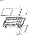
- Fig. 4 is an exploded perspective view of the electrical component unit 16 according to Embodiment 1 of the present invention as viewed from the back.
- the electrical component unit 16 includes a board fixing frame 20 that holds the control board 18 and a board protection sheet metal 21 that covers the upper part of the board fixing frame 20 and protects the control board 18.
- a heat sink 22 for assisting heat release is mounted on the control board 18.
- the heat sink 22 is fixed to the lower part of the board fixing frame 20 by a heat sink fixing sheet metal 23.
- the board fixing frame 20 corresponds to a holder of the present invention.
- Fig. 5 is a perspective view of the board fixing frame 20 according to Embodiment 1 of the present invention as viewed from the back.
- Fig. 6 is an explanatory view of the A-A section of Fig. 5 showing the board fixing frame 20 according to Embodiment 1 of the present invention.
- the back surface of the board fixing frame 20 has a contact surface portion 24 that comes in contact with the partition plate 7 when the outdoor unit 100 of an air-conditioning apparatus is assembled.
- a part of the board fixing frame 20 leading to the contact surface portion 24 that holds the control board 18 constitutes a main body portion 25.
- the back surface of the board fixing frame 20 has a downward protruding V-shaped positioning protrusion 27 that has a gap 26 between positioning protrusion 27 and the contact surface portion 24.
- the positioning protrusion 27 is V-shaped in cross section, and a V-shaped cross section is formed to have a finite width in the front-back direction. Since the positioning protrusion 27 has a finite width, the distal end portion comes into line contact with a receiving surface portion 29 and inclined surface portions 32 that are described later and can slide stably.
- the positioning protrusion 27 is connected by a rib 28 that causes the upper base portion thereof to protrude from the main body portion 25 to the back, and has a gap 26 extending in the front-back direction between the positioning protrusion 27 and the main body portion 25 holding the control board 18 of the board fixing frame 20.
- the positioning protrusion 27 may be provided in a shape other than a V shape, for example, it may be provided in a U shape.
- the positioning protrusion 27 may have a hemispherical distal end having no finite width in the front-back direction.
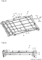
- Fig. 7 is a perspective view of the partition plate 7 according to Embodiment 1 of the present invention as viewed from the back.
- Fig. 8 is an enlarged back view showing the upper part of the partition plate 7 according to Embodiment 1 of the present invention as viewed from the back.
- a planar receiving surface portion 29 for receiving the board fixing frame 20 is provided in the upper part of the standing partition plate 7.
- the receiving surface portion 29 comes into contact with the rib 28 of the board fixing frame 20, and the electrical component unit 16 is supported by the partition plate 7. Therefore, the receiving surface portion 29 has substantially the same shape as the rib 28 so that the rib 28 can be put on the receiving surface portion 29.
- a planar supporting surface portion 30 for receiving the board fixing frame 20 in the front-back direction is provided in the upper part of the portion bent forward of the upright partition plate 7.
- the receiving surface portion 29 is provided with, in its middle part, a cutout portion 31 into which the positioning protrusion 27 is inserted.
- the cutout portion 31 is a space, and when the receiving surface portion 29 and the rib 28 of the board fixing frame 20 are brought into contact with each other, the positioning protrusion 27 is caused to protrude downward.
- Inclined surface portions 32 that are inclined downward from the receiving surface portion 29 and guide the positioning protrusion 27 to the cutout portion 31 are provided at end portions of the receiving surface portion 29 that lead to the cutout portion 31.
- the inclined surface portions 32 are bent obliquely downward from the receiving surface portion 29.
- the inclined surface portions 32 are formed in a pair on both left and right sides of the cutout portion 31.
- the inclined surface portions 32 are inclined at an angle along the V-shaped finite width side surface of the positioning protrusion 27. Therefore, the inclined surface portions 32 are brought into contact with the base portion of the positioning protrusion 27 in a state where the positioning protrusion 27 is inserted into the cutout portion 31 and the fixing position of the electrical component unit 16 is determined in the upper part of the partition plate 7.
- the partition plate 7 having the receiving surface portion 29 and the inclined surface portions 32 is made of a sheet of metal.
- the receiving surface portion 29 is formed by bending the upper part of the upright partition plate 7.
- the inclined surface portions 32 are formed by cutting a part of the receiving surface portion 29 from the partition plate 7 at the bending portion of the receiving surface portion 29 and bending it downward.
- the upper end portion 33 of the partition plate 7 adjacent to the cutout portion 31 has substantially the same height as the receiving surface portion 29.
- Fig. 9 is a diagram showing a model of the inclined surface portions 32 of the partition plate 7 according to Embodiment 1 of the present invention.
- the length of the inclined surface portions 32 and the cutout portion 31 in the left-right horizontal direction is defined as 21.
- the pair of inclined surface portions 32 that is line-symmetrical relative to the left-right center line of the cutout portion 31 can be formed to have a maximum length I of half of 21.
- the pair of left and right inclined surface portions 32 may have different lengths.
- One of the inclined surface portions 32 may be formed to be longer than the maximum length I, and the other may be formed to be shorter than the maximum length I.
- Both of the pair of inclined surface portions 32 may be formed to be shorter than the maximum length I. Only one of the inclined surface portions 32 may be formed.
- Fig. 10 is a perspective view showing the heat sink fixing sheet metal 23 according to Embodiment 1 of the present invention.
- the heat sink fixing sheet metal 23 has, in its front part, a screw-fixing portion 34 that is screw-fixed in a state where the positioning protrusion 27 is inserted into the cutout portion 31 and the fixing position of the electrical component unit 16 is determined in the upper part of the partition plate 7.
- the screw-fixing portion 34 is, for example, a screw hole.
- the partition plate 7 has a screw-fixing area (not shown) to which the screw-fixing portion 34 is screw-fixed.
- Fig. 11 is a back view showing a state where the positioning protrusion 27 according to Embodiment 1 of the present invention is slid on the receiving surface portion 29 as viewed from the back.
- Fig. 12 is a back view showing a state where the positioning protrusion 27 according to Embodiment 1 of the present invention is inserted into the cutout portion 31 as viewed from the back.
- Fig. 13 is an explanatory view of the B-B cross section of Fig. 12 showing a state where the positioning protrusion 27 according to Embodiment 1 of the present invention is inserted into the cutout portion 31.
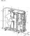
- Fig. 14 is a perspective view showing a state where the electrical component unit 16 according to Embodiment 1 of the present invention is mounted on the partition plate 7.
- the electrical component unit 16 is temporarily placed in a state where the distal end of the positioning protrusion 27 of the board fixing frame 20 is in contact with the receiving surface portion 29 of the partition plate 7.
- the contact surface portion 24 of the main body portion 25 holding the control board 18 of the board fixing frame 20 is in contact with the front side of the partition plate 7 for a period of time including a time when the positioning protrusion 27 is thereafter guided to the cutout portion 31 by the receiving surface portion 29 and the inclined surface portions 32.
- the manufacturing worker slides the electrical component unit 16 in a temporarily placed state in the left-right direction of the outdoor unit 100 of an air-conditioning apparatus, so that the positioning protrusion 27 slides into the cutout portion 31 via the receiving surface portion 29 and the inclined surface portions 32.
- the positioning protrusion 27 is inserted into the cutout portion 31.
- the fixing position of the electrical component unit 16 is determined. As shown in Fig.
- the upper end portion 33 of the partition plate 7 adjacent to the cutout portion 31 enters the gap 26 between the main body portion 25 of the board fixing frame 20 and the positioning protrusion 27 when the positioning protrusion 27 is inserted into the cutout portion 31 and the fixing position of the electrical component unit 16 is determined in the upper part of the partition plate 7.
- the electrical component unit 16 is screw-fixed horizontally to the partition plate 7 at the screw-fixing portion 34 provided in the heat sink fixing sheet metal 23. As a result, the state where the electrical component unit 16 is mounted on the partition plate 7 as shown in Fig. 14 is completed.
- the outdoor unit 100 of an air-conditioning apparatus includes a fan chamber 5 in which a propeller fan 11 is provided and a machine chamber 6 in which a compressor 14 is provided.
- the outdoor unit 100 of an air-conditioning apparatus includes an upright partition plate 7 separating the fan chamber 5 and the machine chamber 6.
- the outdoor unit 100 of an air-conditioning apparatus includes an electrical component unit 16 having a control board 18 on which electrical components for controlling the air-conditioning apparatus are mounted and a board fixing frame 20 that holds the control board 18 and is fixed to the upper part of the partition plate 7.
- the partition plate 7 is provided with, in its upper part, a planar receiving surface portion 29 for receiving the board fixing frame 20.
- the board fixing frame 20 is provided with a positioning protrusion 27 protruding downward.
- a cutout portion 31 into which the positioning protrusion 27 is inserted is formed in the receiving surface portion 29.
- Inclined surface portions 32 that are inclined downward from the receiving surface portion 29 and guide the positioning protrusion 27 to the cutout portion 31 are provided at end portions of the receiving surface portion 29 that lead to the cutout portion 31.
- the positioning protrusion 27 is smoothly guided to the cutout portion 31 by the inclined surface portions 32, and the positioning protrusion 27 can be positioned in the cutout portion 31. Therefore, when the electrical component unit 16 is mounted, the fixing position of the electrical component unit 16 is easily determined, and the work efficiency at the time of manufacturing can be improved. Further, since the positioning protrusion 27 is guided downward by the inclined surface portions 32, the impact on the electrical component unit 16 caused by falling of the electrical component unit 16 for a distance corresponding to the height of the positioning protrusion 27 when the positioning protrusion 27 is positioned in the cutout portion 31 can be mitigated. Therefore, the electrical component unit 16 is less likely to malfunction, and the electrical component unit 16 can be mounted.
- the inclined surface portions 32 come into contact with the base portion of the positioning protrusion 27 in a state where the positioning protrusion 27 is inserted into the cutout portion 31 and the fixing position of the electrical component unit 16 is determined in the upper part of the partition plate 7.
- the inclined surface portions 32 come into contact with the base portion of the positioning protrusion 27, and the positioning protrusion 27 can stably be positioned in the cutout portion 31. Therefore, the fixing position of the electrical component unit 16 is accurately determined in the upper part of the partition plate 7, work such as screw-fixing to the electrical component unit 16 after positioning can be performed quickly, and the work efficiency at the time of manufacturing can be improved.
- the partition plate 7 having the receiving surface portion 29 and the inclined surface portions 32 is made of a sheet of metal.
- the receiving surface portion 29 is formed by bending the upper part of the partition plate 7.
- the inclined surface portions 32 are formed by cutting a part of the receiving surface portion 29 and bending it downward.
- the inclined surface portions 32 are formed in pairs on both sides of the cutout portion 31 by cutting a part of the receiving surface portion 29.
- the positioning protrusion 27 is smoothly guided from either side of the cutout portion 31 by the pair of inclined surface portions 32, and the positioning protrusion 27 can be positioned in the cutout portion 31.
- a gap 26 is provided between the positioning protrusion 27 and the main body portion 25 holding the control board 18 of the board fixing frame 20.
- the upper end portion 33 of the partition plate 7 adjacent to the cutout portion 31 enters the gap 26 when the positioning protrusion 27 is inserted into the cutout portion 31 and the fixing position of the electrical component unit 16 is fixed in the upper part of the partition plate 7.
- the upper end portion 33 of the partition plate 7 adjacent to the cutout portion 31 enters the gap 26, and the electrical component unit 16 can be prevented from being displaced away from the partition plate 7 in the front-back direction. Further, at this time, since the positioning protrusion 27 is inserted into the cutout portions 31, the electrical component unit 16 can also be prevented from being displaced in the left-right direction and the vertical direction. Therefore, the fixing position of the electrical component unit 16 is accurately determined in the upper part of the partition plate 7 in all directions, and work such as screw-fixing to the electrical component unit 16 after positioning can be performed quickly, and the work efficiency at the time of manufacturing can be improved.
- the positioning protrusion 27 is V-shaped.
- the positioning protrusion 27 can smoothly move relative to the receiving surface portion 29 and the inclined surface portions 32.
- Embodiment 1 there is provided a screw-fixing portion 34 that is screw-fixed in a state where the positioning protrusion 27 is inserted into the cutout portion 31 and the fixing position of the electrical component unit 16 is determined in the upper part of the partition plate 7.
- the electrical component unit 16 can be easily screw-fixed to the partition plate 7 at the screw-fixing portion 34, and the work efficiency at the time of manufacturing can be improved.
- the main body portion 25 holding the control board 18 of the board fixing frame 20 comes into contact with the partition plate 7 when the positioning protrusion 27 is guided to the cutout portion 31 by the receiving surface portion 29 and the inclined surface portions 32.
- the positioning protrusion 27 cannot determine the guide position relative to the receiving surface portion 29 and the inclined surface portions 32. Therefore, the positioning protrusion 27 is smoothly guided to the cutout portion 31 by the receiving surface portion 29 and the inclined surface portions 32.
Landscapes
- Engineering & Computer Science (AREA)
- Chemical & Material Sciences (AREA)
- Combustion & Propulsion (AREA)
- Mechanical Engineering (AREA)
- General Engineering & Computer Science (AREA)
- Other Air-Conditioning Systems (AREA)
Abstract
Description
- The present invention relates to an outdoor unit of an air-conditioning apparatus in which the fixing position of an electrical component unit is determined and the electrical component unit is mounted.
- In a conventional outdoor unit of an air-conditioning apparatus, when mounting an electrical component unit, the electrical component unit is positioned by inserting a protruding portion of a cover of the electrical component unit into an insertion hole provided in a partition plate. Then, the electrical component unit is screw-fixed from the upper part of the outdoor unit of an air-conditioning apparatus (see, for example, Patent Literature 1).
- Patent Literature 1: Japanese Unexamined Patent Application Publication No.
2005-147466 - In an outdoor unit of an air-conditioning apparatus, generally, an electrical component unit is disposed in the upper part of the outdoor unit of an air-conditioning apparatus to avoid trouble caused by dew condensation water in the refrigerant pipe or dripping of drain water generated during operation. However, the increase in the size of the outdoor unit of an air-conditioning apparatus accompanying the recent expansion of the cooling and heating capacity has resulted in an increase in the height of the outdoor unit due to an increase in the number of rows of the heat exchanger for the purpose of increasing the capacity.
- As a result, when the outdoor unit of an air-conditioning apparatus is placed on the work table at the time of manufacture of the outdoor unit of an air-conditioning apparatus, the mounting position of the electrical component unit becomes so high that it is difficult for the worker to visually check and to determine the fixing position of the electrical component unit. Therefore, it may be necessary for the worker to climb on a step stool to a height at which the worker can visually check the screw hole to reliably mount the electrical component unit. As a result, the work efficiency at the time of manufacture is deteriorated.
- The present invention is aimed at solving the above problem, and an object thereof is to provide an outdoor unit of an air-conditioning apparatus in which when an electrical component unit is mounted, the fixing position of the electrical component unit is easily determined, and the work efficiency at the time of manufacture is improved.
- An outdoor unit of an air-conditioning apparatus of an embodiment of the present invention includes a fan chamber in which a fan is provided and a machine chamber in which a compressor is provided, a partition plate separating the fan chamber and the machine chamber, and an electrical component unit having a control board on which an electrical component is mounted and a holder that holds the control board and is fixed to an upper part of the partition plate. The partition plate is provided with, in its upper part, a planar receiving surface portion for receiving the holder. The holder is provided with a positioning protrusion protruding downward. A cutout portion into which the positioning protrusion is inserted is formed in the receiving surface portion. At least one inclined surface portion that is inclined downward from the receiving surface portion and guides the positioning protrusion to the cutout portion is provided at an end portion of the receiving surface portion that leads to the cutout portion.
- According to the outdoor unit of an air-conditioning apparatus of an embodiment of the present invention, at least one inclined surface portion that is inclined downward from the receiving surface portion and guides the positioning protrusion to the cutout portion is provided at an end portion of the receiving surface portion that leads to the cutout portion. Whereby, the positioning protrusion is guided smoothly to the cutout portion by the inclined surface portion, and the positioning protrusion can be positioned in the cutout portion. Therefore, when the electrical component unit is mounted, the fixing position of the electrical component unit is easily determined, and the work efficiency at the time of manufacturing can be improved.
-
- [
Fig. 1] Fig. 1 is a perspective view showing an external appearance of an outdoor unit of an air-conditioning apparatus according toEmbodiment 1 of the present invention. - [
Fig. 2] Fig. 2 is an exploded perspective view showing the interior of the outdoor unit of an air-conditioning apparatus according toEmbodiment 1 of the present invention. - [
Fig. 3] Fig. 3 is a perspective view of the electrical component unit according toEmbodiment 1 of the present invention as viewed from the back. - [
Fig. 4] Fig. 4 is an exploded perspective view of the electrical component unit according toEmbodiment 1 of the present invention as viewed from the back. - [
Fig. 5] Fig. 5 is a perspective view of the board fixing frame according toEmbodiment 1 of the present invention as viewed from a back. - [
Fig. 6] Fig. 6 is an explanatory view of the A-A cross section ofFig. 5 showing the board fixing frame according toEmbodiment 1 of the present invention. - [
Fig. 7] Fig. 7 is a perspective view of the partition plate according toEmbodiment 1 of the present invention as viewed from the back. - [
Fig. 8] Fig. 8 is an enlarged back view showing the upper part of the partition plate according toEmbodiment 1 of the present invention as viewed from the back. - [
Fig. 9] Fig. 9 is a diagram showing a model of the inclined surface portions of the partition plate according toEmbodiment 1 of the present invention. - [
Fig. 10] Fig. 10 is a perspective view showing the heat sink fixing sheet metal according toEmbodiment 1 of the present invention. - [
Fig. 11] Fig. 11 is a back view showing a state where the positioning protrusion according toEmbodiment 1 of the present invention is slid on the receiving surface portion as viewed from the back. - [
Fig. 12] Fig. 12 is a back view showing a state where the positioning protrusion according toEmbodiment 1 of the present invention is inserted into the cutout portion as viewed from the back. - [
Fig. 13] Fig. 13 is an explanatory view of the B-B cross section ofFig. 12 showing a state where the positioning protrusion according toEmbodiment 1 of the present invention is inserted into the cutout portion. - [
Fig. 14] Fig. 14 is a perspective view showing a state where the electrical component unit according toEmbodiment 1 of the present invention is mounted on the partition plate. - Hereinafter, an outdoor unit of an air-conditioning apparatus in the present invention will be described with reference to the drawings. In the following drawings, the relationship of sizes of the components may differ from that of actual ones. In the following drawings, those denoted by the same reference numerals are the same or equivalent, and this applies throughout the entire text of the specification. Furthermore, the forms of components described in the full text of the specification are merely illustrative, and the present invention should not be limited to these descriptions.
-
Fig. 1 is a perspective view showing an external appearance of anoutdoor unit 100 of an air-conditioning apparatus according toEmbodiment 1 of the present invention.Fig. 2 is an exploded perspective view showing the interior of theoutdoor unit 100 of an air-conditioning apparatus according toEmbodiment 1 of the present invention. As shown inFigs. 1 and2 , the outline of theoutdoor unit 100 of an air-conditioning apparatus is covered by afront plate 1, aside plate 2, atop plate 3, and aprotective cover 4. In theoutdoor unit 100 of an air-conditioning apparatus, afan chamber 5 and amachine chamber 6 are provided. Thefan chamber 5 and themachine room 6 are separated by anupright partition plate 7. Components inside theoutdoor unit 100 of an air-conditioning apparatus are held on the bottom surface of abottom plate 9 havingleg portions 8. - A
heat exchanger 10, apropeller fan 11 disposed in front of theheat exchanger 10, amotor 12 to which thepropeller fan 11 is attached, and amotor mounting base 13 holding themotor 12 are provided in thefan chamber 5. - When the
propeller fan 11 operates, air flows into theoutdoor unit 100 of an air-conditioning apparatus from the back and the left through theheat exchanger 10. The air flowing into theoutdoor unit 100 of an air-conditioning apparatus flows through theheat exchanger 10 in the ventilation direction, passes through thepropeller fan 11, and flows out to the front of theoutdoor unit 100 of an air-conditioning apparatus. Thus, for example, during the cooling operation, the refrigerant in theheat exchanger 10 is cooled by heat exchange with inflowing air, and the air passing through theheat exchanger 10 is heated after heat exchange with the refrigerant. For example, during the heating operation, the refrigerant in theheat exchanger 10 is heated by heat exchange with inflowing air, and the air passing through theheat exchanger 10 is cooled after heat exchange with the refrigerant. - A
compressor 14, arefrigerant pipe 15, anelectrical component unit 16, and apower supply board 17 are provided in themachine chamber 6. The refrigerant sent from an indoor unit (not shown) is compressed by thecompressor 14, passes through therefrigerant pipe 15, and is sent to theheat exchanger 10. Theelectrical component unit 16 has acontrol board 18 on which electrical components for controlling the air-conditioning apparatus are mounted, and supplies power to each component. Theelectrical component unit 16 has a substantially cuboid shape that is thin in the vertical direction. Thepower supply board 17 draws electricity from the power supply to thecontrol board 18. Aterminal block 19 for connecting theoutdoor unit 100 of an air-conditioning apparatus and the indoor unit (not shown) with a communication wire is screw-fixed to thepower supply board 17. -
Fig. 3 is a perspective view of theelectrical component unit 16 according toEmbodiment 1 of the present invention as viewed from the back.Fig. 4 is an exploded perspective view of theelectrical component unit 16 according toEmbodiment 1 of the present invention as viewed from the back. As shown inFigs. 3 and4 , theelectrical component unit 16 includes aboard fixing frame 20 that holds thecontrol board 18 and a boardprotection sheet metal 21 that covers the upper part of theboard fixing frame 20 and protects thecontrol board 18. Aheat sink 22 for assisting heat release is mounted on thecontrol board 18. Theheat sink 22 is fixed to the lower part of theboard fixing frame 20 by a heat sink fixingsheet metal 23. Here, theboard fixing frame 20 corresponds to a holder of the present invention. -
Fig. 5 is a perspective view of theboard fixing frame 20 according toEmbodiment 1 of the present invention as viewed from the back.Fig. 6 is an explanatory view of the A-A section ofFig. 5 showing theboard fixing frame 20 according toEmbodiment 1 of the present invention. As shown inFigs. 5 and 6 , the back surface of theboard fixing frame 20 has acontact surface portion 24 that comes in contact with thepartition plate 7 when theoutdoor unit 100 of an air-conditioning apparatus is assembled. Here, a part of theboard fixing frame 20 leading to thecontact surface portion 24 that holds thecontrol board 18 constitutes amain body portion 25. - The back surface of the
board fixing frame 20 has a downward protruding V-shapedpositioning protrusion 27 that has agap 26 betweenpositioning protrusion 27 and thecontact surface portion 24. Thepositioning protrusion 27 is V-shaped in cross section, and a V-shaped cross section is formed to have a finite width in the front-back direction. Since thepositioning protrusion 27 has a finite width, the distal end portion comes into line contact with a receivingsurface portion 29 andinclined surface portions 32 that are described later and can slide stably. Thepositioning protrusion 27 is connected by arib 28 that causes the upper base portion thereof to protrude from themain body portion 25 to the back, and has agap 26 extending in the front-back direction between the positioningprotrusion 27 and themain body portion 25 holding thecontrol board 18 of theboard fixing frame 20. Thepositioning protrusion 27 may be provided in a shape other than a V shape, for example, it may be provided in a U shape. Thepositioning protrusion 27 may have a hemispherical distal end having no finite width in the front-back direction. -
Fig. 7 is a perspective view of thepartition plate 7 according toEmbodiment 1 of the present invention as viewed from the back.Fig. 8 is an enlarged back view showing the upper part of thepartition plate 7 according toEmbodiment 1 of the present invention as viewed from the back. As shown inFigs. 7 and8 , a planarreceiving surface portion 29 for receiving theboard fixing frame 20 is provided in the upper part of the standingpartition plate 7. The receivingsurface portion 29 comes into contact with therib 28 of theboard fixing frame 20, and theelectrical component unit 16 is supported by thepartition plate 7. Therefore, the receivingsurface portion 29 has substantially the same shape as therib 28 so that therib 28 can be put on the receivingsurface portion 29. When theelectrical component unit 16 is mounted, thepositioning protrusion 27 of theboard fixing frame 20 contacts and slides on the receivingsurface portion 29. A planar supportingsurface portion 30 for receiving theboard fixing frame 20 in the front-back direction is provided in the upper part of the portion bent forward of theupright partition plate 7. - The receiving
surface portion 29 is provided with, in its middle part, acutout portion 31 into which thepositioning protrusion 27 is inserted. Thecutout portion 31 is a space, and when the receivingsurface portion 29 and therib 28 of theboard fixing frame 20 are brought into contact with each other, thepositioning protrusion 27 is caused to protrude downward. -
Inclined surface portions 32 that are inclined downward from the receivingsurface portion 29 and guide thepositioning protrusion 27 to thecutout portion 31 are provided at end portions of the receivingsurface portion 29 that lead to thecutout portion 31. Theinclined surface portions 32 are bent obliquely downward from the receivingsurface portion 29. Theinclined surface portions 32 are formed in a pair on both left and right sides of thecutout portion 31. Theinclined surface portions 32 are inclined at an angle along the V-shaped finite width side surface of thepositioning protrusion 27. Therefore, theinclined surface portions 32 are brought into contact with the base portion of thepositioning protrusion 27 in a state where thepositioning protrusion 27 is inserted into thecutout portion 31 and the fixing position of theelectrical component unit 16 is determined in the upper part of thepartition plate 7. - As shown in
Fig. 7 , thepartition plate 7 having the receivingsurface portion 29 and theinclined surface portions 32 is made of a sheet of metal. The receivingsurface portion 29 is formed by bending the upper part of theupright partition plate 7. Theinclined surface portions 32 are formed by cutting a part of the receivingsurface portion 29 from thepartition plate 7 at the bending portion of the receivingsurface portion 29 and bending it downward. Theupper end portion 33 of thepartition plate 7 adjacent to thecutout portion 31 has substantially the same height as the receivingsurface portion 29. -
Fig. 9 is a diagram showing a model of theinclined surface portions 32 of thepartition plate 7 according toEmbodiment 1 of the present invention. As shown inFig. 9 , the length of theinclined surface portions 32 and thecutout portion 31 in the left-right horizontal direction is defined as 21. In this case, the pair ofinclined surface portions 32 that is line-symmetrical relative to the left-right center line of thecutout portion 31 can be formed to have a maximum length I of half of 21. The pair of left and rightinclined surface portions 32 may have different lengths. One of theinclined surface portions 32 may be formed to be longer than the maximum length I, and the other may be formed to be shorter than the maximum length I. Both of the pair ofinclined surface portions 32 may be formed to be shorter than the maximum length I. Only one of theinclined surface portions 32 may be formed. -
Fig. 10 is a perspective view showing the heat sink fixingsheet metal 23 according toEmbodiment 1 of the present invention. As shown inFig. 10 , the heat sink fixingsheet metal 23 has, in its front part, a screw-fixingportion 34 that is screw-fixed in a state where thepositioning protrusion 27 is inserted into thecutout portion 31 and the fixing position of theelectrical component unit 16 is determined in the upper part of thepartition plate 7. By screw-fixing thescrew fixing portion 34 to thepartition plate 7, theelectrical component unit 16 is fixed to thepartition plate 7. The screw-fixingportion 34 is, for example, a screw hole. Thepartition plate 7 has a screw-fixing area (not shown) to which the screw-fixingportion 34 is screw-fixed. In a state where thepositioning protrusion 27 is inserted into thecutout portion 31 and the fixing position of theelectrical component unit 16 is determined in the upper part of thepartition plate 7, the screw insertion position of the screw-fixingportion 34 coincides with the screw insertion position of the screw fixing portion of thepartition plate 7. -
Fig. 11 is a back view showing a state where thepositioning protrusion 27 according toEmbodiment 1 of the present invention is slid on the receivingsurface portion 29 as viewed from the back.Fig. 12 is a back view showing a state where thepositioning protrusion 27 according toEmbodiment 1 of the present invention is inserted into thecutout portion 31 as viewed from the back.Fig. 13 is an explanatory view of the B-B cross section ofFig. 12 showing a state where thepositioning protrusion 27 according toEmbodiment 1 of the present invention is inserted into thecutout portion 31.Fig. 14 is a perspective view showing a state where theelectrical component unit 16 according toEmbodiment 1 of the present invention is mounted on thepartition plate 7. - The
electrical component unit 16 is temporarily placed in a state where the distal end of thepositioning protrusion 27 of theboard fixing frame 20 is in contact with the receivingsurface portion 29 of thepartition plate 7. In this temporarily placed state, thecontact surface portion 24 of themain body portion 25 holding thecontrol board 18 of theboard fixing frame 20 is in contact with the front side of thepartition plate 7 for a period of time including a time when thepositioning protrusion 27 is thereafter guided to thecutout portion 31 by the receivingsurface portion 29 and theinclined surface portions 32. Then, as shown inFig. 11 , the manufacturing worker slides theelectrical component unit 16 in a temporarily placed state in the left-right direction of theoutdoor unit 100 of an air-conditioning apparatus, so that thepositioning protrusion 27 slides into thecutout portion 31 via the receivingsurface portion 29 and theinclined surface portions 32. As shown inFig. 12 , thepositioning protrusion 27 is inserted into thecutout portion 31. As a result, the fixing position of theelectrical component unit 16 is determined. As shown inFig. 13 , theupper end portion 33 of thepartition plate 7 adjacent to thecutout portion 31 enters thegap 26 between themain body portion 25 of theboard fixing frame 20 and thepositioning protrusion 27 when thepositioning protrusion 27 is inserted into thecutout portion 31 and the fixing position of theelectrical component unit 16 is determined in the upper part of thepartition plate 7. Thereafter, theelectrical component unit 16 is screw-fixed horizontally to thepartition plate 7 at the screw-fixingportion 34 provided in the heat sink fixingsheet metal 23. As a result, the state where theelectrical component unit 16 is mounted on thepartition plate 7 as shown inFig. 14 is completed. - According to
Embodiment 1, theoutdoor unit 100 of an air-conditioning apparatus includes afan chamber 5 in which apropeller fan 11 is provided and amachine chamber 6 in which acompressor 14 is provided. Theoutdoor unit 100 of an air-conditioning apparatus includes anupright partition plate 7 separating thefan chamber 5 and themachine chamber 6. Theoutdoor unit 100 of an air-conditioning apparatus includes anelectrical component unit 16 having acontrol board 18 on which electrical components for controlling the air-conditioning apparatus are mounted and aboard fixing frame 20 that holds thecontrol board 18 and is fixed to the upper part of thepartition plate 7. Thepartition plate 7 is provided with, in its upper part, a planarreceiving surface portion 29 for receiving theboard fixing frame 20. Theboard fixing frame 20 is provided with apositioning protrusion 27 protruding downward. Acutout portion 31 into which thepositioning protrusion 27 is inserted is formed in the receivingsurface portion 29.Inclined surface portions 32 that are inclined downward from the receivingsurface portion 29 and guide thepositioning protrusion 27 to thecutout portion 31 are provided at end portions of the receivingsurface portion 29 that lead to thecutout portion 31. - Due to this configuration, the
positioning protrusion 27 is smoothly guided to thecutout portion 31 by theinclined surface portions 32, and thepositioning protrusion 27 can be positioned in thecutout portion 31. Therefore, when theelectrical component unit 16 is mounted, the fixing position of theelectrical component unit 16 is easily determined, and the work efficiency at the time of manufacturing can be improved. Further, since thepositioning protrusion 27 is guided downward by theinclined surface portions 32, the impact on theelectrical component unit 16 caused by falling of theelectrical component unit 16 for a distance corresponding to the height of thepositioning protrusion 27 when thepositioning protrusion 27 is positioned in thecutout portion 31 can be mitigated. Therefore, theelectrical component unit 16 is less likely to malfunction, and theelectrical component unit 16 can be mounted. - According to
Embodiment 1, theinclined surface portions 32 come into contact with the base portion of thepositioning protrusion 27 in a state where thepositioning protrusion 27 is inserted into thecutout portion 31 and the fixing position of theelectrical component unit 16 is determined in the upper part of thepartition plate 7. - According to this configuration, the
inclined surface portions 32 come into contact with the base portion of thepositioning protrusion 27, and thepositioning protrusion 27 can stably be positioned in thecutout portion 31. Therefore, the fixing position of theelectrical component unit 16 is accurately determined in the upper part of thepartition plate 7, work such as screw-fixing to theelectrical component unit 16 after positioning can be performed quickly, and the work efficiency at the time of manufacturing can be improved. - According to
Embodiment 1, thepartition plate 7 having the receivingsurface portion 29 and theinclined surface portions 32 is made of a sheet of metal. The receivingsurface portion 29 is formed by bending the upper part of thepartition plate 7. Theinclined surface portions 32 are formed by cutting a part of the receivingsurface portion 29 and bending it downward. - According to this configuration, simplification of configuration can be obtained, the number of parts can be reduced, and cost reduction can be achieved.
- According to
Embodiment 1, theinclined surface portions 32 are formed in pairs on both sides of thecutout portion 31 by cutting a part of the receivingsurface portion 29. - According to this configuration, the
positioning protrusion 27 is smoothly guided from either side of thecutout portion 31 by the pair ofinclined surface portions 32, and thepositioning protrusion 27 can be positioned in thecutout portion 31. - According to
Embodiment 1, agap 26 is provided between the positioningprotrusion 27 and themain body portion 25 holding thecontrol board 18 of theboard fixing frame 20. Theupper end portion 33 of thepartition plate 7 adjacent to thecutout portion 31 enters thegap 26 when thepositioning protrusion 27 is inserted into thecutout portion 31 and the fixing position of theelectrical component unit 16 is fixed in the upper part of thepartition plate 7. - Due to this configuration, the
upper end portion 33 of thepartition plate 7 adjacent to thecutout portion 31 enters thegap 26, and theelectrical component unit 16 can be prevented from being displaced away from thepartition plate 7 in the front-back direction. Further, at this time, since thepositioning protrusion 27 is inserted into thecutout portions 31, theelectrical component unit 16 can also be prevented from being displaced in the left-right direction and the vertical direction. Therefore, the fixing position of theelectrical component unit 16 is accurately determined in the upper part of thepartition plate 7 in all directions, and work such as screw-fixing to theelectrical component unit 16 after positioning can be performed quickly, and the work efficiency at the time of manufacturing can be improved. - According to
Embodiment 1, thepositioning protrusion 27 is V-shaped. - Due to this configuration, it is possible to reduce the area where the lower end of the
positioning protrusion 27 contacts the receivingsurface portion 29 and theinclined surface portions 32. Therefore, thepositioning protrusion 27 can smoothly move relative to the receivingsurface portion 29 and theinclined surface portions 32. - According to
Embodiment 1, there is provided a screw-fixingportion 34 that is screw-fixed in a state where thepositioning protrusion 27 is inserted into thecutout portion 31 and the fixing position of theelectrical component unit 16 is determined in the upper part of thepartition plate 7. - According to this configuration, after the fixing position of the
electrical component unit 16 is accurately determined in the upper part of thepartition plate 7, theelectrical component unit 16 can be easily screw-fixed to thepartition plate 7 at the screw-fixingportion 34, and the work efficiency at the time of manufacturing can be improved. - According to
Embodiment 1, themain body portion 25 holding thecontrol board 18 of theboard fixing frame 20 comes into contact with thepartition plate 7 when thepositioning protrusion 27 is guided to thecutout portion 31 by the receivingsurface portion 29 and theinclined surface portions 32. - According to this configuration, it is possible to prevent a situation where the
main body portion 25 holding thecontrol board 18 of theboard fixing frame 20 does not come into contact with thepartition plate 7, theelectrical component unit 16 is separated from thepartition plate 7, and thepositioning protrusion 27 cannot determine the guide position relative to the receivingsurface portion 29 and theinclined surface portions 32. Therefore, thepositioning protrusion 27 is smoothly guided to thecutout portion 31 by the receivingsurface portion 29 and theinclined surface portions 32. - It should be noted that embodiments disclosed above are examples in all respects and are not restrictive. It is intended that the scope of the present invention is defined not by the above description but by the claims and includes all modifications within meaning and scope equivalent to the claims.
- 1
front plate 2side plate 3top plate 4protective cover 5fan chamber 6machine chamber 7partition plate 8leg portion 9bottom plate 10heat exchanger 11propeller fan 12motor 13motor mounting base 14compressor 15refrigerant pipe 16electrical component unit 17power supply board 18control board 19terminal block 20board fixing frame 21 boardprotection sheet metal 22heat sink 23 heat sink fixingsheet metal 24contact surface portion 25main body portion 26gap 27positioning protrusion 28rib 29 receivingsurface portion 30 supportingsurface portion 31cutout portion 32inclined surface portion 33upper end portion 34 screw-fixingportion 100 outdoor unit
Claims (8)
- An outdoor unit of an air-conditioning apparatus comprising:a fan chamber in which a fan is provided and a machine chamber in which a compressor is provided;a partition plate separating the fan chamber and the machine chamber; andan electrical component unit having a control board on which an electrical component is mounted and a holder that holds the control board and is fixed to an upper part of the partition plate,wherein the partition plate is provided with, in its upper part, a planar receiving surface portion for receiving the holder,wherein the holder is provided with a positioning protrusion protruding downward,wherein a cutout portion into which the positioning protrusion is inserted is formed in the receiving surface portion, andwherein at least one inclined surface portion that is inclined downward from the receiving surface portion and guides the positioning protrusion to the cutout portion is provided at an end portion of the receiving surface portion that leads to the cutout portion.
- The outdoor unit of an air-conditioning apparatus of claim 1, wherein the at least one inclined surface portion comes into contact with a base portion of the positioning protrusion in a state where the positioning protrusion is inserted into the cutout portion and a fixing position of the electrical component unit is determined in the upper part of the partition plate.
- The outdoor unit of an air-conditioning apparatus of claim 1 or 2,
wherein the partition plate having the receiving surface portion and the at least one inclined surface portion is made of a sheet of metal,
wherein the receiving surface portion is formed by bending the upper part of the partition plate, and
wherein the at least one inclined surface portion is formed by cutting a part of the receiving surface portion and bending it downward. - The outdoor unit of an air-conditioning apparatus of claim 3, wherein the at least one inclined surface portion comprise a pair of inclined surface portions formed on both sides of the cutout portion by cutting a part of the receiving surface portion.
- The outdoor unit of an air-conditioning apparatus of any one of claims 1 to 4,
wherein the positioning protrusion has a gap between the positioning protrusion and a main body portion holding the control board of the holder, and
wherein an upper end portion of the partition plate adjacent to the cutout portion enters the gap when the positioning protrusion is inserted into the cutout portion and a fixing position of the electrical component unit is determined in the upper part of the partition plate. - The outdoor unit of an air-conditioning apparatus of any one of claims 1 to 5, wherein the positioning protrusion is V-shaped.
- The outdoor unit of an air-conditioning apparatus of any one of claims 1 to 6, comprising a screw-fixing portion screw-fixed in a state where the positioning protrusion is inserted into the cutout portion and a fixing position of the electrical component unit is determined in the upper part of the partition plate.
- The outdoor unit of an air-conditioning apparatus of any one of claims 3 to 7, wherein a main body portion holding the control board of the holder comes into contact with the partition plate when the positioning protrusion is guided to the cutout portion by the receiving surface portion and the at least one inclined surface portion.
Applications Claiming Priority (1)
| Application Number | Priority Date | Filing Date | Title |
|---|---|---|---|
| PCT/JP2016/086005 WO2018104990A1 (en) | 2016-12-05 | 2016-12-05 | Outdoor unit of air conditioning device |
Publications (3)
| Publication Number | Publication Date |
|---|---|
| EP3550214A1 true EP3550214A1 (en) | 2019-10-09 |
| EP3550214A4 EP3550214A4 (en) | 2019-11-20 |
| EP3550214B1 EP3550214B1 (en) | 2023-03-29 |
Family
ID=62490818
Family Applications (1)
| Application Number | Title | Priority Date | Filing Date |
|---|---|---|---|
| EP16923212.1A Active EP3550214B1 (en) | 2016-12-05 | 2016-12-05 | Outdoor unit of air conditioning device |
Country Status (5)
| Country | Link |
|---|---|
| US (1) | US10962239B2 (en) |
| EP (1) | EP3550214B1 (en) |
| JP (1) | JP6939816B2 (en) |
| CN (1) | CN110036243A (en) |
| WO (1) | WO2018104990A1 (en) |
Families Citing this family (8)
| Publication number | Priority date | Publication date | Assignee | Title |
|---|---|---|---|---|
| US12352462B2 (en) * | 2018-05-15 | 2025-07-08 | Carrier Corporation | Air handling unit |
| CN109094798A (en) * | 2018-10-10 | 2018-12-28 | 深圳市道通智能航空技术有限公司 | A kind of unmanned plane and its winged control component |
| DE112019006774T5 (en) * | 2019-01-30 | 2021-10-14 | Mitsubishi Electric Corporation | Indoor unit of an air conditioner |
| DE112019007594T5 (en) * | 2019-08-01 | 2022-04-14 | Mitsubishi Electric Corporation | Outdoor unit for air conditioning device and air conditioning device |
| US11976828B2 (en) * | 2020-03-30 | 2024-05-07 | Mitsubishi Electric Corporation | Outdoor unit of air-conditioning apparatus |
| CN113175635A (en) * | 2021-04-21 | 2021-07-27 | 深圳市派乐光电技术有限公司 | Green energy-concerving and environment-protective high light efficiency light structure |
| CN113606683B (en) * | 2021-08-12 | 2022-07-19 | 创维空调科技(安徽)有限公司 | Shell structure and air conditioner |
| JP2024052212A (en) * | 2022-09-30 | 2024-04-11 | パナソニックIpマネジメント株式会社 | Heat pump equipment |
Family Cites Families (16)
| Publication number | Priority date | Publication date | Assignee | Title |
|---|---|---|---|---|
| JP3549357B2 (en) * | 1997-03-10 | 2004-08-04 | 松下電器産業株式会社 | Outdoor unit for separation type air conditioner |
| JP3966013B2 (en) * | 2002-02-25 | 2007-08-29 | 日産自動車株式会社 | Opening cover structure |
| JP4022858B2 (en) | 2002-03-18 | 2007-12-19 | 三菱電機株式会社 | Air conditioner with floor heating |
| JP4079071B2 (en) | 2003-11-13 | 2008-04-23 | 松下電器産業株式会社 | Heat source unit |
| JP2006064208A (en) * | 2004-08-25 | 2006-03-09 | Mitsubishi Electric Corp | Air conditioner outdoor unit and air conditioner electrical unit unit |
| JP2010071518A (en) * | 2008-09-17 | 2010-04-02 | Daikin Ind Ltd | Electronic component unit for air conditioner and outdoor unit for the air conditioner |
| JP4941479B2 (en) * | 2009-02-02 | 2012-05-30 | ダイキン工業株式会社 | Electrical component module and outdoor unit equipped with the same |
| IT1400737B1 (en) * | 2009-05-20 | 2013-07-02 | Sanyo Electric Co | EXTERNAL UNIT FOR HEAT EXCHANGE, PARTICULARLY IN HEAT EXCHANGERS AND SIMILAR. |
| JP4807445B2 (en) * | 2009-07-14 | 2011-11-02 | ダイキン工業株式会社 | Outdoor unit |
| CN203718977U (en) * | 2014-01-10 | 2014-07-16 | 广东美的制冷设备有限公司 | Air conditioner outdoor unit |
| JP6223262B2 (en) * | 2014-04-04 | 2017-11-01 | 三菱電機株式会社 | Air conditioner outdoor unit |
| JP6333108B2 (en) * | 2014-08-04 | 2018-05-30 | 三菱電機株式会社 | Air conditioner heat source side unit |
| JP2016043748A (en) * | 2014-08-21 | 2016-04-04 | 河西工業株式会社 | Connection structure of vehicular interior components |
| CN204335267U (en) * | 2015-01-05 | 2015-05-13 | 广东美的制冷设备有限公司 | Air conditioner and its electric control box assembly |
| CN105444292A (en) * | 2016-01-14 | 2016-03-30 | 珠海格力电器股份有限公司 | Motor support and air condensing units |
| CN106016503A (en) * | 2016-06-15 | 2016-10-12 | 珠海格力电器股份有限公司 | Air conditioner |
-
2016
- 2016-12-05 CN CN201680091267.3A patent/CN110036243A/en active Pending
- 2016-12-05 WO PCT/JP2016/086005 patent/WO2018104990A1/en not_active Ceased
- 2016-12-05 JP JP2018555325A patent/JP6939816B2/en not_active Expired - Fee Related
- 2016-12-05 US US16/330,214 patent/US10962239B2/en not_active Expired - Fee Related
- 2016-12-05 EP EP16923212.1A patent/EP3550214B1/en active Active
Also Published As
| Publication number | Publication date |
|---|---|
| JPWO2018104990A1 (en) | 2019-06-27 |
| WO2018104990A1 (en) | 2018-06-14 |
| EP3550214B1 (en) | 2023-03-29 |
| US10962239B2 (en) | 2021-03-30 |
| JP6939816B2 (en) | 2021-09-22 |
| US20190285288A1 (en) | 2019-09-19 |
| EP3550214A4 (en) | 2019-11-20 |
| CN110036243A (en) | 2019-07-19 |
Similar Documents
| Publication | Publication Date | Title |
|---|---|---|
| EP3550214B1 (en) | Outdoor unit of air conditioning device | |
| EP2206978A1 (en) | Outdoor unit for air conditioner | |
| US20170205086A1 (en) | Outdoor unit of air conditioner | |
| US9388993B2 (en) | Outdoor unit of air-conditioning apparatus | |
| JP2012233614A (en) | Outdoor unit for air conditioner device | |
| JP5873994B2 (en) | Air conditioner outdoor unit | |
| JP7031059B2 (en) | Heat pump cycle device and heat pump water heater | |
| JP5879534B2 (en) | Outdoor unit for cover and air conditioner | |
| KR20150091616A (en) | Outdoor unit for air conditoiner | |
| JP6242245B2 (en) | Air conditioner indoor unit | |
| CN111971511A (en) | Outdoor unit of air conditioner | |
| JP6298542B2 (en) | Outdoor unit of refrigeration cycle equipment | |
| CN109587946B (en) | Air conditioner | |
| JP6882716B2 (en) | Outdoor unit of air conditioner | |
| EP3346199A1 (en) | Outdoor unit | |
| EP4108999B1 (en) | Mobile air conditioner | |
| JPWO2020075243A1 (en) | Outdoor unit of air conditioner | |
| JP6014856B2 (en) | Panel heater | |
| JP6984162B2 (en) | Outdoor unit of air conditioner | |
| WO2022054128A1 (en) | Outdoor unit | |
| CN217884325U (en) | Accurate refrigeration air supply arrangement | |
| CN215989720U (en) | Waterproof power distribution cabinet for electrical engineering | |
| JP6639525B2 (en) | Air conditioner indoor unit | |
| JP2009186106A (en) | Outdoor unit | |
| KR20090040499A (en) | Outdoor unit of air conditioner |
Legal Events
| Date | Code | Title | Description |
|---|---|---|---|
| STAA | Information on the status of an ep patent application or granted ep patent |
Free format text: STATUS: THE INTERNATIONAL PUBLICATION HAS BEEN MADE |
|
| PUAI | Public reference made under article 153(3) epc to a published international application that has entered the european phase |
Free format text: ORIGINAL CODE: 0009012 |
|
| STAA | Information on the status of an ep patent application or granted ep patent |
Free format text: STATUS: REQUEST FOR EXAMINATION WAS MADE |
|
| 17P | Request for examination filed |
Effective date: 20190423 |
|
| AK | Designated contracting states |
Kind code of ref document: A1 Designated state(s): AL AT BE BG CH CY CZ DE DK EE ES FI FR GB GR HR HU IE IS IT LI LT LU LV MC MK MT NL NO PL PT RO RS SE SI SK SM TR |
|
| AX | Request for extension of the european patent |
Extension state: BA ME |
|
| A4 | Supplementary search report drawn up and despatched |
Effective date: 20191021 |
|
| RIC1 | Information provided on ipc code assigned before grant |
Ipc: F24F 1/22 20110101AFI20191015BHEP |
|
| DAV | Request for validation of the european patent (deleted) | ||
| DAX | Request for extension of the european patent (deleted) | ||
| STAA | Information on the status of an ep patent application or granted ep patent |
Free format text: STATUS: EXAMINATION IS IN PROGRESS |
|
| 17Q | First examination report despatched |
Effective date: 20201209 |
|
| GRAP | Despatch of communication of intention to grant a patent |
Free format text: ORIGINAL CODE: EPIDOSNIGR1 |
|
| STAA | Information on the status of an ep patent application or granted ep patent |
Free format text: STATUS: GRANT OF PATENT IS INTENDED |
|
| INTG | Intention to grant announced |
Effective date: 20221024 |
|
| GRAS | Grant fee paid |
Free format text: ORIGINAL CODE: EPIDOSNIGR3 |
|
| GRAA | (expected) grant |
Free format text: ORIGINAL CODE: 0009210 |
|
| STAA | Information on the status of an ep patent application or granted ep patent |
Free format text: STATUS: THE PATENT HAS BEEN GRANTED |
|
| AK | Designated contracting states |
Kind code of ref document: B1 Designated state(s): AL AT BE BG CH CY CZ DE DK EE ES FI FR GB GR HR HU IE IS IT LI LT LU LV MC MK MT NL NO PL PT RO RS SE SI SK SM TR |
|
| REG | Reference to a national code |
Ref country code: CH Ref legal event code: EP |
|
| REG | Reference to a national code |
Ref country code: DE Ref legal event code: R096 Ref document number: 602016078603 Country of ref document: DE |
|
| REG | Reference to a national code |
Ref country code: AT Ref legal event code: REF Ref document number: 1556931 Country of ref document: AT Kind code of ref document: T Effective date: 20230415 |
|
| REG | Reference to a national code |
Ref country code: IE Ref legal event code: FG4D |
|
| REG | Reference to a national code |
Ref country code: LT Ref legal event code: MG9D |
|
| PG25 | Lapsed in a contracting state [announced via postgrant information from national office to epo] |
Ref country code: RS Free format text: LAPSE BECAUSE OF FAILURE TO SUBMIT A TRANSLATION OF THE DESCRIPTION OR TO PAY THE FEE WITHIN THE PRESCRIBED TIME-LIMIT Effective date: 20230329 Ref country code: NO Free format text: LAPSE BECAUSE OF FAILURE TO SUBMIT A TRANSLATION OF THE DESCRIPTION OR TO PAY THE FEE WITHIN THE PRESCRIBED TIME-LIMIT Effective date: 20230629 Ref country code: LV Free format text: LAPSE BECAUSE OF FAILURE TO SUBMIT A TRANSLATION OF THE DESCRIPTION OR TO PAY THE FEE WITHIN THE PRESCRIBED TIME-LIMIT Effective date: 20230329 Ref country code: LT Free format text: LAPSE BECAUSE OF FAILURE TO SUBMIT A TRANSLATION OF THE DESCRIPTION OR TO PAY THE FEE WITHIN THE PRESCRIBED TIME-LIMIT Effective date: 20230329 Ref country code: HR Free format text: LAPSE BECAUSE OF FAILURE TO SUBMIT A TRANSLATION OF THE DESCRIPTION OR TO PAY THE FEE WITHIN THE PRESCRIBED TIME-LIMIT Effective date: 20230329 |
|
| REG | Reference to a national code |
Ref country code: NL Ref legal event code: MP Effective date: 20230329 |
|
| REG | Reference to a national code |
Ref country code: AT Ref legal event code: MK05 Ref document number: 1556931 Country of ref document: AT Kind code of ref document: T Effective date: 20230329 |
|
| P01 | Opt-out of the competence of the unified patent court (upc) registered |
Effective date: 20230711 |
|
| PG25 | Lapsed in a contracting state [announced via postgrant information from national office to epo] |
Ref country code: SE Free format text: LAPSE BECAUSE OF FAILURE TO SUBMIT A TRANSLATION OF THE DESCRIPTION OR TO PAY THE FEE WITHIN THE PRESCRIBED TIME-LIMIT Effective date: 20230329 Ref country code: NL Free format text: LAPSE BECAUSE OF FAILURE TO SUBMIT A TRANSLATION OF THE DESCRIPTION OR TO PAY THE FEE WITHIN THE PRESCRIBED TIME-LIMIT Effective date: 20230329 Ref country code: GR Free format text: LAPSE BECAUSE OF FAILURE TO SUBMIT A TRANSLATION OF THE DESCRIPTION OR TO PAY THE FEE WITHIN THE PRESCRIBED TIME-LIMIT Effective date: 20230630 Ref country code: FI Free format text: LAPSE BECAUSE OF FAILURE TO SUBMIT A TRANSLATION OF THE DESCRIPTION OR TO PAY THE FEE WITHIN THE PRESCRIBED TIME-LIMIT Effective date: 20230329 |
|
| PG25 | Lapsed in a contracting state [announced via postgrant information from national office to epo] |
Ref country code: SM Free format text: LAPSE BECAUSE OF FAILURE TO SUBMIT A TRANSLATION OF THE DESCRIPTION OR TO PAY THE FEE WITHIN THE PRESCRIBED TIME-LIMIT Effective date: 20230329 Ref country code: RO Free format text: LAPSE BECAUSE OF FAILURE TO SUBMIT A TRANSLATION OF THE DESCRIPTION OR TO PAY THE FEE WITHIN THE PRESCRIBED TIME-LIMIT Effective date: 20230329 Ref country code: PT Free format text: LAPSE BECAUSE OF FAILURE TO SUBMIT A TRANSLATION OF THE DESCRIPTION OR TO PAY THE FEE WITHIN THE PRESCRIBED TIME-LIMIT Effective date: 20230731 Ref country code: ES Free format text: LAPSE BECAUSE OF FAILURE TO SUBMIT A TRANSLATION OF THE DESCRIPTION OR TO PAY THE FEE WITHIN THE PRESCRIBED TIME-LIMIT Effective date: 20230329 Ref country code: EE Free format text: LAPSE BECAUSE OF FAILURE TO SUBMIT A TRANSLATION OF THE DESCRIPTION OR TO PAY THE FEE WITHIN THE PRESCRIBED TIME-LIMIT Effective date: 20230329 Ref country code: AT Free format text: LAPSE BECAUSE OF FAILURE TO SUBMIT A TRANSLATION OF THE DESCRIPTION OR TO PAY THE FEE WITHIN THE PRESCRIBED TIME-LIMIT Effective date: 20230329 |
|
| PG25 | Lapsed in a contracting state [announced via postgrant information from national office to epo] |
Ref country code: SK Free format text: LAPSE BECAUSE OF FAILURE TO SUBMIT A TRANSLATION OF THE DESCRIPTION OR TO PAY THE FEE WITHIN THE PRESCRIBED TIME-LIMIT Effective date: 20230329 Ref country code: PL Free format text: LAPSE BECAUSE OF FAILURE TO SUBMIT A TRANSLATION OF THE DESCRIPTION OR TO PAY THE FEE WITHIN THE PRESCRIBED TIME-LIMIT Effective date: 20230329 Ref country code: IS Free format text: LAPSE BECAUSE OF FAILURE TO SUBMIT A TRANSLATION OF THE DESCRIPTION OR TO PAY THE FEE WITHIN THE PRESCRIBED TIME-LIMIT Effective date: 20230729 |
|
| REG | Reference to a national code |
Ref country code: DE Ref legal event code: R097 Ref document number: 602016078603 Country of ref document: DE |
|
| PG25 | Lapsed in a contracting state [announced via postgrant information from national office to epo] |
Ref country code: DK Free format text: LAPSE BECAUSE OF FAILURE TO SUBMIT A TRANSLATION OF THE DESCRIPTION OR TO PAY THE FEE WITHIN THE PRESCRIBED TIME-LIMIT Effective date: 20230329 Ref country code: CZ Free format text: LAPSE BECAUSE OF FAILURE TO SUBMIT A TRANSLATION OF THE DESCRIPTION OR TO PAY THE FEE WITHIN THE PRESCRIBED TIME-LIMIT Effective date: 20230329 |
|
| PGFP | Annual fee paid to national office [announced via postgrant information from national office to epo] |
Ref country code: DE Payment date: 20231031 Year of fee payment: 8 |
|
| PLBE | No opposition filed within time limit |
Free format text: ORIGINAL CODE: 0009261 |
|
| STAA | Information on the status of an ep patent application or granted ep patent |
Free format text: STATUS: NO OPPOSITION FILED WITHIN TIME LIMIT |
|
| 26N | No opposition filed |
Effective date: 20240103 |
|
| PG25 | Lapsed in a contracting state [announced via postgrant information from national office to epo] |
Ref country code: SI Free format text: LAPSE BECAUSE OF FAILURE TO SUBMIT A TRANSLATION OF THE DESCRIPTION OR TO PAY THE FEE WITHIN THE PRESCRIBED TIME-LIMIT Effective date: 20230329 |
|
| PG25 | Lapsed in a contracting state [announced via postgrant information from national office to epo] |
Ref country code: SI Free format text: LAPSE BECAUSE OF FAILURE TO SUBMIT A TRANSLATION OF THE DESCRIPTION OR TO PAY THE FEE WITHIN THE PRESCRIBED TIME-LIMIT Effective date: 20230329 Ref country code: IT Free format text: LAPSE BECAUSE OF FAILURE TO SUBMIT A TRANSLATION OF THE DESCRIPTION OR TO PAY THE FEE WITHIN THE PRESCRIBED TIME-LIMIT Effective date: 20230329 |
|
| REG | Reference to a national code |
Ref country code: CH Ref legal event code: PL |
|
| PG25 | Lapsed in a contracting state [announced via postgrant information from national office to epo] |
Ref country code: LU Free format text: LAPSE BECAUSE OF NON-PAYMENT OF DUE FEES Effective date: 20231205 |
|
| PG25 | Lapsed in a contracting state [announced via postgrant information from national office to epo] |
Ref country code: MC Free format text: LAPSE BECAUSE OF FAILURE TO SUBMIT A TRANSLATION OF THE DESCRIPTION OR TO PAY THE FEE WITHIN THE PRESCRIBED TIME-LIMIT Effective date: 20230329 |
|
| GBPC | Gb: european patent ceased through non-payment of renewal fee |
Effective date: 20231205 |
|
| REG | Reference to a national code |
Ref country code: BE Ref legal event code: MM Effective date: 20231231 |
|
| PG25 | Lapsed in a contracting state [announced via postgrant information from national office to epo] |
Ref country code: MC Free format text: LAPSE BECAUSE OF FAILURE TO SUBMIT A TRANSLATION OF THE DESCRIPTION OR TO PAY THE FEE WITHIN THE PRESCRIBED TIME-LIMIT Effective date: 20230329 Ref country code: LU Free format text: LAPSE BECAUSE OF NON-PAYMENT OF DUE FEES Effective date: 20231205 |
|
| REG | Reference to a national code |
Ref country code: IE Ref legal event code: MM4A |
|
| PG25 | Lapsed in a contracting state [announced via postgrant information from national office to epo] |
Ref country code: IE Free format text: LAPSE BECAUSE OF NON-PAYMENT OF DUE FEES Effective date: 20231205 |
|
| PG25 | Lapsed in a contracting state [announced via postgrant information from national office to epo] |
Ref country code: GB Free format text: LAPSE BECAUSE OF NON-PAYMENT OF DUE FEES Effective date: 20231205 |
|
| PG25 | Lapsed in a contracting state [announced via postgrant information from national office to epo] |
Ref country code: BE Free format text: LAPSE BECAUSE OF NON-PAYMENT OF DUE FEES Effective date: 20231231 |
|
| PG25 | Lapsed in a contracting state [announced via postgrant information from national office to epo] |
Ref country code: FR Free format text: LAPSE BECAUSE OF NON-PAYMENT OF DUE FEES Effective date: 20231231 |
|
| PG25 | Lapsed in a contracting state [announced via postgrant information from national office to epo] |
Ref country code: CH Free format text: LAPSE BECAUSE OF NON-PAYMENT OF DUE FEES Effective date: 20231231 |
|
| PG25 | Lapsed in a contracting state [announced via postgrant information from national office to epo] |
Ref country code: IE Free format text: LAPSE BECAUSE OF NON-PAYMENT OF DUE FEES Effective date: 20231205 Ref country code: GB Free format text: LAPSE BECAUSE OF NON-PAYMENT OF DUE FEES Effective date: 20231205 Ref country code: FR Free format text: LAPSE BECAUSE OF NON-PAYMENT OF DUE FEES Effective date: 20231231 Ref country code: CH Free format text: LAPSE BECAUSE OF NON-PAYMENT OF DUE FEES Effective date: 20231231 Ref country code: BE Free format text: LAPSE BECAUSE OF NON-PAYMENT OF DUE FEES Effective date: 20231231 |
|
| PG25 | Lapsed in a contracting state [announced via postgrant information from national office to epo] |
Ref country code: BG Free format text: LAPSE BECAUSE OF FAILURE TO SUBMIT A TRANSLATION OF THE DESCRIPTION OR TO PAY THE FEE WITHIN THE PRESCRIBED TIME-LIMIT Effective date: 20230329 |
|
| PG25 | Lapsed in a contracting state [announced via postgrant information from national office to epo] |
Ref country code: BG Free format text: LAPSE BECAUSE OF FAILURE TO SUBMIT A TRANSLATION OF THE DESCRIPTION OR TO PAY THE FEE WITHIN THE PRESCRIBED TIME-LIMIT Effective date: 20230329 |
|
| REG | Reference to a national code |
Ref country code: DE Ref legal event code: R119 Ref document number: 602016078603 Country of ref document: DE |
|
| PG25 | Lapsed in a contracting state [announced via postgrant information from national office to epo] |
Ref country code: CY Free format text: LAPSE BECAUSE OF FAILURE TO SUBMIT A TRANSLATION OF THE DESCRIPTION OR TO PAY THE FEE WITHIN THE PRESCRIBED TIME-LIMIT; INVALID AB INITIO Effective date: 20161205 |
|
| PG25 | Lapsed in a contracting state [announced via postgrant information from national office to epo] |
Ref country code: HU Free format text: LAPSE BECAUSE OF FAILURE TO SUBMIT A TRANSLATION OF THE DESCRIPTION OR TO PAY THE FEE WITHIN THE PRESCRIBED TIME-LIMIT; INVALID AB INITIO Effective date: 20161205 |
|
| PG25 | Lapsed in a contracting state [announced via postgrant information from national office to epo] |
Ref country code: DE Free format text: LAPSE BECAUSE OF NON-PAYMENT OF DUE FEES Effective date: 20250701 |
|
| PG25 | Lapsed in a contracting state [announced via postgrant information from national office to epo] |
Ref country code: TR Free format text: LAPSE BECAUSE OF FAILURE TO SUBMIT A TRANSLATION OF THE DESCRIPTION OR TO PAY THE FEE WITHIN THE PRESCRIBED TIME-LIMIT Effective date: 20230329 |