EP3550145B1 - Pumping apparatus - Google Patents
Pumping apparatus Download PDFInfo
- Publication number
- EP3550145B1 EP3550145B1 EP19163777.6A EP19163777A EP3550145B1 EP 3550145 B1 EP3550145 B1 EP 3550145B1 EP 19163777 A EP19163777 A EP 19163777A EP 3550145 B1 EP3550145 B1 EP 3550145B1
- Authority
- EP
- European Patent Office
- Prior art keywords
- compartment
- zone
- opening
- channel
- fluid
- Prior art date
- Legal status (The legal status is an assumption and is not a legal conclusion. Google has not performed a legal analysis and makes no representation as to the accuracy of the status listed.)
- Active
Links
Images


Classifications
-
- F—MECHANICAL ENGINEERING; LIGHTING; HEATING; WEAPONS; BLASTING
- F04—POSITIVE - DISPLACEMENT MACHINES FOR LIQUIDS; PUMPS FOR LIQUIDS OR ELASTIC FLUIDS
- F04C—ROTARY-PISTON, OR OSCILLATING-PISTON, POSITIVE-DISPLACEMENT MACHINES FOR LIQUIDS; ROTARY-PISTON, OR OSCILLATING-PISTON, POSITIVE-DISPLACEMENT PUMPS
- F04C2/00—Rotary-piston machines or pumps
- F04C2/08—Rotary-piston machines or pumps of intermeshing-engagement type, i.e. with engagement of co-operating members similar to that of toothed gearing
- F04C2/10—Rotary-piston machines or pumps of intermeshing-engagement type, i.e. with engagement of co-operating members similar to that of toothed gearing of internal-axis type with the outer member having more teeth or tooth-equivalents, e.g. rollers, than the inner member
- F04C2/102—Rotary-piston machines or pumps of intermeshing-engagement type, i.e. with engagement of co-operating members similar to that of toothed gearing of internal-axis type with the outer member having more teeth or tooth-equivalents, e.g. rollers, than the inner member the two members rotating simultaneously around their respective axes
-
- F—MECHANICAL ENGINEERING; LIGHTING; HEATING; WEAPONS; BLASTING
- F04—POSITIVE - DISPLACEMENT MACHINES FOR LIQUIDS; PUMPS FOR LIQUIDS OR ELASTIC FLUIDS
- F04C—ROTARY-PISTON, OR OSCILLATING-PISTON, POSITIVE-DISPLACEMENT MACHINES FOR LIQUIDS; ROTARY-PISTON, OR OSCILLATING-PISTON, POSITIVE-DISPLACEMENT PUMPS
- F04C11/00—Combinations of two or more machines or pumps, each being of rotary-piston or oscillating-piston type; Pumping installations
- F04C11/001—Combinations of two or more machines or pumps, each being of rotary-piston or oscillating-piston type; Pumping installations of similar working principle
-
- F—MECHANICAL ENGINEERING; LIGHTING; HEATING; WEAPONS; BLASTING
- F04—POSITIVE - DISPLACEMENT MACHINES FOR LIQUIDS; PUMPS FOR LIQUIDS OR ELASTIC FLUIDS
- F04C—ROTARY-PISTON, OR OSCILLATING-PISTON, POSITIVE-DISPLACEMENT MACHINES FOR LIQUIDS; ROTARY-PISTON, OR OSCILLATING-PISTON, POSITIVE-DISPLACEMENT PUMPS
- F04C14/00—Control of, monitoring of, or safety arrangements for, machines, pumps or pumping installations
- F04C14/24—Control of, monitoring of, or safety arrangements for, machines, pumps or pumping installations characterised by using valves controlling pressure or flow rate, e.g. discharge valves or unloading valves
- F04C14/26—Control of, monitoring of, or safety arrangements for, machines, pumps or pumping installations characterised by using valves controlling pressure or flow rate, e.g. discharge valves or unloading valves using bypass channels
-
- F—MECHANICAL ENGINEERING; LIGHTING; HEATING; WEAPONS; BLASTING
- F04—POSITIVE - DISPLACEMENT MACHINES FOR LIQUIDS; PUMPS FOR LIQUIDS OR ELASTIC FLUIDS
- F04C—ROTARY-PISTON, OR OSCILLATING-PISTON, POSITIVE-DISPLACEMENT MACHINES FOR LIQUIDS; ROTARY-PISTON, OR OSCILLATING-PISTON, POSITIVE-DISPLACEMENT PUMPS
- F04C15/00—Component parts, details or accessories of machines, pumps or pumping installations, not provided for in groups F04C2/00 - F04C14/00
- F04C15/06—Arrangements for admission or discharge of the working fluid, e.g. constructional features of the inlet or outlet
- F04C15/064—Arrangements for admission or discharge of the working fluid, e.g. constructional features of the inlet or outlet with inlet and outlet valves specially adapted for rotary or oscillating piston machines or pumps
-
- F—MECHANICAL ENGINEERING; LIGHTING; HEATING; WEAPONS; BLASTING
- F04—POSITIVE - DISPLACEMENT MACHINES FOR LIQUIDS; PUMPS FOR LIQUIDS OR ELASTIC FLUIDS
- F04C—ROTARY-PISTON, OR OSCILLATING-PISTON, POSITIVE-DISPLACEMENT MACHINES FOR LIQUIDS; ROTARY-PISTON, OR OSCILLATING-PISTON, POSITIVE-DISPLACEMENT PUMPS
- F04C2/00—Rotary-piston machines or pumps
- F04C2/08—Rotary-piston machines or pumps of intermeshing-engagement type, i.e. with engagement of co-operating members similar to that of toothed gearing
- F04C2/12—Rotary-piston machines or pumps of intermeshing-engagement type, i.e. with engagement of co-operating members similar to that of toothed gearing of other than internal-axis type
- F04C2/14—Rotary-piston machines or pumps of intermeshing-engagement type, i.e. with engagement of co-operating members similar to that of toothed gearing of other than internal-axis type with toothed rotary pistons
- F04C2/18—Rotary-piston machines or pumps of intermeshing-engagement type, i.e. with engagement of co-operating members similar to that of toothed gearing of other than internal-axis type with toothed rotary pistons with similar tooth forms
Definitions
- the present invention relates to a pumping apparatus. It can be used to drive loads, typically in trucks or tipper trucks.
- volumetric gear pumps The use of a plurality of volumetric gear pumps is known, which are used to drive corresponding loads independently of each other.
- the object of the present invention is to propose a pumping apparatus equipped with multiple pumping sections which makes it possible to reverse the direction of rotation in a simple way (without opening the pumping apparatus, but simply by modifying the fluid connections from the outside).
- a further object of the present invention is to implement measures that allow minimising the risk of error during the reversal of the direction of rotation.
- reference number 10 denotes a pumping apparatus.
- the pumping apparatus 10 comprises a first reversible volumetric gear pump 1.
- the first pump 1 comprises:
- the apparatus 10 also comprises a second reversible volumetric gear pump 2.
- the second volumetric pump 2 comprises:
- the first and second pumps 1, 2 can also be defined as the first and second sections of the same pumping apparatus 10.
- the first volumetric pump 1 draws in rotation the second volumetric pump 2, or vice versa.
- a joint can be present which couples a toothed wheel of the first pair 11 (or an element integral therewith) with a toothed wheel of the second pair 21 (or an element integral therewith).
- the first and second pumps 1, 2 are advantageously alongside each other.
- a wheel of the first pair 11 is coaxial with a wheel of the second pair 21.
- the first pump 1 is operatively interposed between a drive shaft connectable to the motor and the second pump 2.
- the motor is suitably electrical or thermal.
- the apparatus 10 further comprises a first channel 13 that places in fluid connection a first zone 121 of the first compartment 12 and a first zone 221 of the second compartment 22.
- the apparatus 10 further comprises a second channel 23 that places in fluid connection a second zone 122 of the first compartment 12 and a second zone 222 of the second compartment 22.
- the apparatus 10 further comprises means 3 for opening/closing the first and second channels 13, 23.
- the apparatus 10 further comprises a first, a second, a third and a fourth openings 14, 15, 24, 25 intended to allow the fluid communication of the pumping apparatus 10 with the outside.
- the apparatus 10 comprises an outer casing 4.
- casing 4 is made of metallic material.
- the first, second, third and fourth openings 14, 15, 24, 25 are fashioned on the casing 4.
- first and third openings 14, 24 are fashioned on a first face 41 of the casing 4.
- the second and fourth opening 15, 25 are instead fashioned on a second face 42 of the casing 4.
- the second face 42 and the first face 41 are fashioned in separate areas of the casing 4.
- the second face 42 is opposite the first face 41 (see for example figures 7 and 8 ).
- the first and second openings 14, 15 allow direct access to the first and second zones 121, 122 of the first compartment 12.
- the third and fourth openings 24, 25 allow direct access to an intermediate position of the first and second channels 13, 23.
- the third and fourth openings 24, 25 respectively allow access to the first and second zones 221, 222 of the second compartment 22.
- the apparatus 10 can assume at least a first and a second operating configurations. They correspond to distinct modes of operation associated with the reversibility of the first and second pumps 1, 2. In the second operating configuration the rotation direction of the first and of the second pair 11, 21 of wheels is opposite to that assumed in the first operating configuration.
- Figures 1, 2 , 3 , 7, 8 exemplify the first configuration.
- the first zone 121 of the first compartment 12 and the first zone 221 of the second compartment 22 define a suction respectively of the first and second pumps 1, 2, while the second zone 122 of the first compartment 12 and the second zone 222 of the second compartment 22 respectively define a delivery of the first and second pumps 1, 2.
- the means 3 for opening/closing the first and second channels 13, 23 block the second channel 23. In this way they prevent the fluid communication between the second zone 122 of the first compartment 12 and the second zone 222 of the second compartment 22.
- the means 3 for opening/closing in the first configuration allow the fluid communication of the first zone 121 of the first compartment 12 and the first zone 221 of the second compartment 22 through the first channel 13.
- Figures 4 , 5 and 6 exemplify the second operating configuration.
- the second zone 122 of the first compartment 12 and the second zone 222 of the second compartment 22 respectively define a suction of the first and second pumps 1, 2, while the first zone 121 of the first compartment 12 and the second zone 221 of the second compartment 22 respectively define a delivery of the first and second pumps 1, 2.
- the means 3 for opening/closing the first and second channels 13, 23 block the first channel 13, thereby preventing communication between the first zone 121 of the first compartment 11 and the first zone 221 of the second compartment 22. Furthermore, in the second configuration they allow the fluid communication between the second zone 122 of the first compartment 12 and the second zone 222 of the second compartment 22 through the second channel 23.
- both the first and second configuration there is a single inlet of the operating fluid in the apparatus 10: it is the first opening 14 in the first configuration and the second opening 15 in the second configuration. Having a single suction zone is particularly convenient.
- both the first and second configuration there are at least two independent outlets of the operating fluid from the apparatus 10: for example, in the first configuration they are the second and the fourth opening 15, 25. They thus make it possible to deliver to two loads which are separate, and in an independent manner.
- the apparatus 1 advantageously comprises a first hole 51 which connects the first channel 13 and the outside of the casing 4.
- the means 3 for opening and closing the first and second channels 13, 23 comprise a first and a second stoppers 31, 32.
- the first stopper 31, if applied to the first hole 51, allows the passage of fluid between the first and second compartments 12, 22 through the first channel 13.
- the second stopper 32 if applied to the first hole 51, prevents the passage of fluid between the first and the second compartments 12, 22 through the first channel 13.
- the second stopper 32 can comprise a pair of gaskets. If applied to the first hole 51, the second stopper 32 blocks the first channel 13, preventing the passage of fluid. In this case, the first channel 13 is blocked by a portion of the second stopper 32 interposed between the pair of gaskets (which therefore contribute to a sealing action).
- this pair of gaskets could be absent.
- the seal would be defined by the metal walls of the second stopper 32 (and would therefore be purely mechanical).
- the apparatus 1 also comprises a second hole 52 which connects the second channel 23 and the outside of the casing 4.
- the first and second stoppers 31, 32 can also be fitted into the second hole 52.
- the second stopper 32 is fitted into the second hole 52 and the first stopper 31 is fitted into the first hole 51.
- the second stopper 32 can prevent the fluid connection between the first and second compartments 12, 22 through the second channel 23.
- the first stopper 31 instead allows the connection between the first and second compartments 12, 22 through the first channel 13.
- the second stopper 32 is fitted into the first hole 51 and the first stopper 31 is fitted into the second hole 52.
- the second stopper 32 prevents the fluid connection between the first and second compartments 12, 22 through the first channel 13 while the first stopper 31 allows the fluid connection between the first and second compartments 12, 22 through the second channel 23.
- the first hole 51 extends between the first channel 13 and the third opening 24 while the second hole 52 extends between the second channel 23 and the fourth opening 25.
- the second stopper 32 is suitable for penetrating further into the apparatus 10 (or better inside the casing 4) with respect to the first stopper 31. In this way (unlike the first stopper 31), it can reach and block the first or the second channel 13, 23.
- the second stopper 32 comprises:
- the cavity 324 is crossed by the fluid present along the second channel 23 and coming from the second pump 2 (thus allowing the crossing of the fourth opening 25).
- the cavity 324 is crossed by the fluid present along the first channel 13 and coming from the second pump 2 (thus allowing the crossing of the third opening 24).
- a third stopper 33 different from the first and second stoppers 31, 32 is used to block one among the third and the fourth openings 24, 25 (the other remaining open for the outflow of the fluid coming from the delivery of the second pump 2).
- the first and second stoppers 31, 32 exert the function of allowing or not allowing the passage through the first or the second channel 13, 23.
- the third stopper 33 is not fittable in the first and second holes 51, 52 intended for the first and second stoppers 31, 32. This is to minimise the risk of accidental errors by users when reversing the motion of the apparatus (which could compromise proper operation).
- the operating principle of the schematic solution of figures 3 and 6 is also valid for the solution of figures 11 and 12 .
- an inlet of the operating fluid into the apparatus 10 coincides with an inlet of operating fluid into the first pump 1.
- the delivery of the first and second pumps 1, 2 are not mutually communicating. Therefore, an independent delivery of various loads is possible.
- the delivery of the first and second pumps 1, 2 are located side by side (or otherwise formed along a same side of the casing 4).
- the pumping apparatus 1 comprises a lubrication path 90 of bushings 94 supporting one or more support shafts of the first and/or second pair of toothed wheels 11, 21 (see figures 9 and 10 ).
- the lubrication path 90 draws the fluid from the first and/or from the second compartment 12, 22 and conveys it in an environment 93 downstream of the bushings 94 and at least partially delimited by an oil seal.
- This environment 93 must be at low pressure in order to avoid the breakage of the oil seal separating it from the outside. In fact, the outside will typically have atmospheric pressure.
- the apparatus 1 comprises a hinge 91 that connects the first and second holes 51, 52 and which is in communication with such environment (through a section 92).
- such switch 91 connects a bottom of the first hole 51 and a bottom of the second hole 52.
- the present invention achieves important advantages.
Landscapes
- Engineering & Computer Science (AREA)
- Mechanical Engineering (AREA)
- General Engineering & Computer Science (AREA)
- Physics & Mathematics (AREA)
- Fluid Mechanics (AREA)
- Rotary Pumps (AREA)
- Massaging Devices (AREA)
- Infusion, Injection, And Reservoir Apparatuses (AREA)
Description
- The present invention relates to a pumping apparatus. It can be used to drive loads, typically in trucks or tipper trucks.
- The use of a plurality of volumetric gear pumps is known, which are used to drive corresponding loads independently of each other.
- Pumping apparatus are disclosed in
GB882248 EP2154372 . - The object of the present invention is to propose a pumping apparatus equipped with multiple pumping sections which makes it possible to reverse the direction of rotation in a simple way (without opening the pumping apparatus, but simply by modifying the fluid connections from the outside). A further object of the present invention is to implement measures that allow minimising the risk of error during the reversal of the direction of rotation.
- The defined technical task and the specified aims are substantially achieved by a pumping apparatus comprising the technical characteristics set forth in one or more of the appended claims.
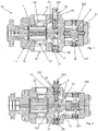
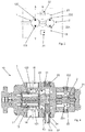
- Further characteristics and advantages of the present invention will become more apparent from the following indicative and therefore nonlimiting description of a pumping apparatus as illustrated in the appended drawings, in which:
-
figures 1 and 2 show sectional views of an apparatus according to the present invention in a first operating configuration, these two sections being conducted through parallel sectional planes which are slightly spaced from one another; -
figure 3 shows a functional diagram of the apparatus in the configuration offigures 1 and 2 ; -
figures 4 and 5 show a sectional view of the apparatus offigures 1 and 2 in a second operating configuration, these two sections being conducted through parallel sectional planes which are slightly spaced from one another; -
figure 6 shows a functional diagram of the apparatus in the configuration offigures 4 and 5 ; -
figures 7 and 8 show views of the apparatus offigure 1 ; -
figures 9 and 10 show further details of the apparatus according to the present invention; -
figures 11 and 12 show a further constructive solution of a pumping apparatus according to the present invention, as an alternative to the apparatus infigures 1-8 . - In the appended figures of the drawings,
reference number 10 denotes a pumping apparatus. - The
pumping apparatus 10 comprises a first reversiblevolumetric gear pump 1. In turn, thefirst pump 1 comprises: - a
first pair 11 of toothed wheels (meshing with each other); - a
first housing compartment 12 for housing thefirst pair 11 of toothed wheels. - The
apparatus 10 also comprises a second reversiblevolumetric gear pump 2. In turn, the secondvolumetric pump 2 comprises: - a
second pair 21 of toothed wheels (meshing with each other); - a
second housing compartment 22 for housing thesecond pair 21 of wheels. - The first and
second pumps same pumping apparatus 10. - The first
volumetric pump 1 draws in rotation the secondvolumetric pump 2, or vice versa. - In this regard, a joint can be present which couples a toothed wheel of the first pair 11 (or an element integral therewith) with a toothed wheel of the second pair 21 (or an element integral therewith). The first and
second pumps first pair 11 is coaxial with a wheel of thesecond pair 21. - There is therefore a single motor which drives both the first and the
second pumps first pump 1 is operatively interposed between a drive shaft connectable to the motor and thesecond pump 2. The motor is suitably electrical or thermal. - The
apparatus 10 further comprises afirst channel 13 that places in fluid connection afirst zone 121 of thefirst compartment 12 and afirst zone 221 of thesecond compartment 22. - The
apparatus 10 further comprises asecond channel 23 that places in fluid connection asecond zone 122 of thefirst compartment 12 and asecond zone 222 of thesecond compartment 22. - The
apparatus 10 further comprises means 3 for opening/closing the first andsecond channels - The
apparatus 10 further comprises a first, a second, a third and afourth openings pumping apparatus 10 with the outside. - Appropriately the
apparatus 10 comprises anouter casing 4. Preferablysuch casing 4 is made of metallic material. - The first, second, third and
fourth openings casing 4. - Preferably the first and
third openings first face 41 of thecasing 4. The second andfourth opening second face 42 of thecasing 4. Thesecond face 42 and thefirst face 41 are fashioned in separate areas of thecasing 4. In particular, thesecond face 42 is opposite the first face 41 (see for examplefigures 7 and 8 ). - The first and
second openings second zones first compartment 12. - In turn, in the solution of
figures 1-10 , the third andfourth openings second channels - Instead, in the solution of
figures 11 and 12 , the third andfourth openings second zones second compartment 22. - The
apparatus 10 can assume at least a first and a second operating configurations. They correspond to distinct modes of operation associated with the reversibility of the first andsecond pumps second pair -
Figures 1, 2 ,3 ,7, 8 exemplify the first configuration. In this case, thefirst zone 121 of thefirst compartment 12 and thefirst zone 221 of thesecond compartment 22 define a suction respectively of the first andsecond pumps second zone 122 of thefirst compartment 12 and thesecond zone 222 of thesecond compartment 22 respectively define a delivery of the first andsecond pumps second channels second channel 23. In this way they prevent the fluid communication between thesecond zone 122 of thefirst compartment 12 and thesecond zone 222 of thesecond compartment 22. The means 3 for opening/closing in the first configuration, however, allow the fluid communication of thefirst zone 121 of thefirst compartment 12 and thefirst zone 221 of thesecond compartment 22 through thefirst channel 13. - Still in the first configuration:
- the
first opening 14 is crossed by the inflowing operating fluid and directed towards thefirst zone 121 of thefirst compartment 11 and thefirst zone 221 of thesecond compartment 12; - the
second opening 15 is crossed by the outflowing operating fluid coming from thesecond zone 122 of the first compartment 11 (and outflowing from the apparatus 1); - the third opening 24 is blocked;
- the
fourth opening 25 is crossed by the outflowing fluid coming from thesecond zone 222 of thesecond compartment 12. -
Figures 4 ,5 and 6 exemplify the second operating configuration. In this configuration, thesecond zone 122 of thefirst compartment 12 and thesecond zone 222 of thesecond compartment 22 respectively define a suction of the first andsecond pumps first zone 121 of thefirst compartment 12 and thesecond zone 221 of thesecond compartment 22 respectively define a delivery of the first andsecond pumps - In the second configuration, the
means 3 for opening/closing the first andsecond channels first channel 13, thereby preventing communication between thefirst zone 121 of thefirst compartment 11 and thefirst zone 221 of thesecond compartment 22. Furthermore, in the second configuration they allow the fluid communication between thesecond zone 122 of thefirst compartment 12 and thesecond zone 222 of thesecond compartment 22 through thesecond channel 23. - In the second configuration:
- the
first opening 14 is crossed by the outflowing operating fluid coming from thefirst zone 121 of thefirst compartment 12; - the
second opening 15 is crossed by the inflowing operating fluid directed towards thesecond zone 122 of thefirst compartment 12 and thesecond zone 222 of thesecond compartment 12; - the
third opening 24 is crossed by the outflowing fluid coming from thefirst zone 221 of thesecond compartment 12; - the
fourth opening 25 is blocked. - In the second configuration, the
fourth opening 25 is blocked. - In both the first and second configuration there is a single inlet of the operating fluid in the apparatus 10: it is the
first opening 14 in the first configuration and thesecond opening 15 in the second configuration. Having a single suction zone is particularly convenient. - In addition, in both the first and second configuration there are at least two independent outlets of the operating fluid from the apparatus 10: for example, in the first configuration they are the second and the
fourth opening - The
apparatus 1 advantageously comprises afirst hole 51 which connects thefirst channel 13 and the outside of thecasing 4. - The
means 3 for opening and closing the first andsecond channels second stoppers - They are applicable to the
casing 4 and fittable in thefirst hole 51. They are applicable to thefirst hole 51 as an alternative to one another. Thefirst stopper 31, if applied to thefirst hole 51, allows the passage of fluid between the first andsecond compartments first channel 13. Instead, thesecond stopper 32, if applied to thefirst hole 51, prevents the passage of fluid between the first and thesecond compartments first channel 13. - The
second stopper 32 can comprise a pair of gaskets. If applied to thefirst hole 51, thesecond stopper 32 blocks thefirst channel 13, preventing the passage of fluid. In this case, thefirst channel 13 is blocked by a portion of thesecond stopper 32 interposed between the pair of gaskets (which therefore contribute to a sealing action). - In an alternative solution, this pair of gaskets could be absent. In this case the seal would be defined by the metal walls of the second stopper 32 (and would therefore be purely mechanical).
- The
apparatus 1 also comprises asecond hole 52 which connects thesecond channel 23 and the outside of thecasing 4. - The first and
second stoppers second hole 52. In the first configuration, thesecond stopper 32 is fitted into thesecond hole 52 and thefirst stopper 31 is fitted into thefirst hole 51. In this case, thesecond stopper 32 can prevent the fluid connection between the first andsecond compartments second channel 23. Thefirst stopper 31 instead allows the connection between the first andsecond compartments first channel 13. In the second configuration, thesecond stopper 32 is fitted into thefirst hole 51 and thefirst stopper 31 is fitted into thesecond hole 52. In this case, thesecond stopper 32 prevents the fluid connection between the first andsecond compartments first channel 13 while thefirst stopper 31 allows the fluid connection between the first andsecond compartments second channel 23. - In the solution exemplified in
figures 1-10 , thefirst hole 51 extends between thefirst channel 13 and thethird opening 24 while thesecond hole 52 extends between thesecond channel 23 and thefourth opening 25. - The
second stopper 32 is suitable for penetrating further into the apparatus 10 (or better inside the casing 4) with respect to thefirst stopper 31. In this way (unlike the first stopper 31), it can reach and block the first or thesecond channel - In the solution exemplified in
figures 1-10 thesecond stopper 32 comprises: - a first and a second
longitudinal end - a
lateral wall 323 which connects the first and second ends 321, 322; - an
internal cavity 324 in communication with the outside at thefirst end 321 and at a zone of thelateral wall 323. - In the first configuration the
cavity 324 is crossed by the fluid present along thesecond channel 23 and coming from the second pump 2 (thus allowing the crossing of the fourth opening 25). - In the second configuration the
cavity 324 is crossed by the fluid present along thefirst channel 13 and coming from the second pump 2 (thus allowing the crossing of the third opening 24). - This arrangement is absent in the solution of
figures 11 and 12 , wherein the outflow of the fluid processed by thesecond pump 2 does not cross thesecond stopper 32, but crosses a different channel. In fact, in this case the first andsecond holes fourth openings figure 11 (which is in the first operating configuration), the outflow of fluid continues to take place through thefourth opening 25 which, however, does not provide for the transit through thestopper 32. In the case wherein the solution offigure 11 was in the second operating configuration, thefourth opening 25 would be stopped while thethird opening 24 would allow the outflow of the fluid processed by thesecond pump 2. - In the solution of
Figure 11 , athird stopper 33 different from the first andsecond stoppers fourth openings 24, 25 (the other remaining open for the outflow of the fluid coming from the delivery of the second pump 2). In this case, even if thesecond stopper 32 is not internally crossed by the fluid, the first andsecond stoppers second channel third stopper 33 is not fittable in the first andsecond holes second stoppers figures 3 and6 is also valid for the solution offigures 11 and 12 . - With reference to any of the solutions exemplified in the appended drawings, regardless of the first or second configuration, an inlet of the operating fluid into the
apparatus 10 coincides with an inlet of operating fluid into thefirst pump 1. - In addition, regardless of the first or second configuration, the delivery of the first and
second pumps second pumps - Advantageously, the
pumping apparatus 1 comprises alubrication path 90 ofbushings 94 supporting one or more support shafts of the first and/or second pair oftoothed wheels 11, 21 (seefigures 9 and 10 ). Thelubrication path 90 draws the fluid from the first and/or from thesecond compartment environment 93 downstream of thebushings 94 and at least partially delimited by an oil seal. Thisenvironment 93 must be at low pressure in order to avoid the breakage of the oil seal separating it from the outside. In fact, the outside will typically have atmospheric pressure. Advantageously, theapparatus 1 comprises acanalisation 91 that connects the first andsecond holes such canalisation 91 connects a bottom of thefirst hole 51 and a bottom of thesecond hole 52. These measures make it possible to ensure that such an environment has the suction pressure of the operating fluid (and therefore low pressure). In this way, the breakage of the oil seal is avoided. - The present invention achieves important advantages.
- Firstly, it allows reversing the direction of rotation in a simple way, without opening the pump, but acting only on the connections accessible from the outside (the channels that connect to the
openings - Furthermore, all the details can be replaced with other technically-equivalent elements. In practice, all the materials used, as well as the dimensions, can be any according to requirements.
Claims (10)
- A pumping apparatus comprising:i) a first reversible volumetric gear pump (1) comprising:- a first pair (11) of toothed wheels;- a first housing compartment (12) for housing the first pair (11) of toothed wheels;ii) a second reversible volumetric gear pump (2) comprising:characterised in that it comprises:- a second pair (21) of toothed wheels; the first volumetric pump (1) drawing in rotation the second volumetric pump (2);- a second housing compartment (22) for housing the second pair (21) of wheels;* a first channel (13) that places in fluid connection a first zone (121) of the first compartment (12) and a first zone (221) of the second compartment (22);* a second channel (23) that places in fluid connection a second zone (122) of the first compartment (12) and a second zone (222) of the second compartment (22);* means (3) for opening/closing the first and the second channel (13, 23);* an outer casing (4) comprising a first, a second, a third and a fourth opening (14, 15, 24, 25) intended to allow the fluid communication of the pumping apparatus (10) with the outside;* means used to block the third and fourth openings (24, 25);in a first operating configuration: said first zone (121) of the first compartment (12) and said first zone (221) of the second compartment (22) defining a suction of the first and of the second pump (1, 2), respectively, said second zone (122) of the first compartment (12) and said second zone (222) of the second compartment (22) defining a delivery of the first and of the second pump (1, 2), respectively, said means (3) for opening/closing the first and the second channel (13, 23) blocking the second channel (23) and allowing the fluid communication of the first zone (121) of the first compartment (12) and of the first zone (221) of the second compartment (22) through the first channel (13); the first opening (14) being crossed by the inflowing operating fluid directed towards the first zone (121) of the first compartment (12) and to the first zone (221) of the second compartment (22); the second opening (15) being crossed by the outflowing operating fluid coming from the second zone (122) of the first compartment (12), the third opening (24) being blocked, the fourth opening (25) being crossed by the outflowing fluid coming from the second zone (222) of the second pump (2);
in a second operating configuration: said second zone (122) of the first compartment (12) and said second zone (222) of the second compartment (22) defining a suction of the first and of the second pump (1, 2), respectively, said first zone (121) of the first compartment (12) and said first zone (221) of the second compartment (22) defining a delivery of the first and of the second pump (1, 2), respectively, said means (3) for opening/closing the first and second channel (13, 23) blocking the first channel (13) and allowing the fluid communication between the second zone (122) of the first compartment (12) and the second zone (222) of the second compartment (22) through the second channel (23); the first opening (14) being crossed by the outflowing operating fluid coming from the first zone (121) of the first compartment (12), the second opening (15) being crossed by the inflowing fluid directed towards the second zone (122) of the first compartment (12) and towards the second zone (222) of the second compartment (22); the third opening (24) being crossed by the outflowing fluid coming from the first zone (221) of the second compartment (2); the fourth opening (25) being blocked;
in the second operating configuration the rotation direction of the first and of the second pair (11, 21) of wheels being opposite to that assumed in the first operating configuration. - The apparatus according to claim 1, characterised in that it comprises a first hole (51) that connects the first channel (13) and the outside of the casing (4), the means (3) for opening and closing the first and the second channel (13, 23) comprising a first and a second stopper (31, 32) applicable to the casing (4) and fittable in said first hole (51); the first stopper (31), if applied to the first hole (51), allowing the passage of fluid between the first and the second compartment (12, 22) through the first channel (13), the second stopper (32), if applied to the first hole (51), preventing the passage of fluid through the first channel (13).
- The apparatus according to claim 2, characterised in that it comprises a second hole (52) that connects the second channel (23) and the outside of the casing (4); the first and the second stopper (31, 32) being fittable also in the second hole (52); in the first configuration the second stopper (32) being fitted in the second hole (52) for stopping the passage of fluid between the first and the second compartment (12, 22) through the second channel (23) and the first stopper (31) being fitted in the first hole (51); in the second configuration the second stopper (32) being fitted in the first hole (51), the first stopper (31) being fitted in the second hole (52) allowing the passage of fluid between the first and the second compartment (12, 22) through the second channel (23).
- The apparatus according to claim 3, characterised in that the first and the second hole (51, 52) are separate and independent with respect to the third and the fourth opening (24, 25).
- The apparatus according to claim 3, characterised in that the first hole (51) extends between the first channel (13) and the third opening (24); the second hole (52) extending between the second channel (23) and the fourth opening (25).
- The apparatus according to any one of claims 2 to 5, characterised in that the second stopper (32) is suitable for penetrating further into the apparatus (10) than the first stopper (31).
- The apparatus according to any one of claims 2 to 6, characterised in that the second stopper (32) comprises:- a first and a second longitudinal end (321, 322);- a lateral wall (323) which connects the first and the second end (321, 322);- an internal cavity (324) in communication with the outside at the first end (321) and at a zone of the lateral wall (323);in the first configuration said cavity (324) being crossed by the fluid present along the second channel (23) and coming from the second pump (2) allowing the crossing of the fourth opening (25);
in the second configuration said cavity (324) being crossed by the fluid present along the first channel (13) and coming from the second pump (2) allowing the crossing of the third opening (24). - The apparatus according to any one of the preceding claims, characterised in that the first and the third opening (14, 24) are fashioned on a first face (41) of said casing (4); the second and the fourth opening (15, 25) being fashioned on a second face (42) of said casing (4), the second face (42) being opposite the first face (41).
- The apparatus according to any one of the preceding claims, characterised in that both in the first and in the second configuration an inlet of the operating fluid into the apparatus (10) coincides with an inlet of operating fluid into the first pump (1).
- The apparatus according to any one of the preceding claims, characterised in that both in the first and in the second configuration the delivery of the first and the second pump (1, 2) are not mutually communicating and are located alongside each other.
Applications Claiming Priority (1)
| Application Number | Priority Date | Filing Date | Title |
|---|---|---|---|
| IT102018000004230A IT201800004230A1 (en) | 2018-04-05 | 2018-04-05 | PUMPING APPARATUS |
Publications (2)
| Publication Number | Publication Date |
|---|---|
| EP3550145A1 EP3550145A1 (en) | 2019-10-09 |
| EP3550145B1 true EP3550145B1 (en) | 2020-08-05 |
Family
ID=62751394
Family Applications (1)
| Application Number | Title | Priority Date | Filing Date |
|---|---|---|---|
| EP19163777.6A Active EP3550145B1 (en) | 2018-04-05 | 2019-03-19 | Pumping apparatus |
Country Status (3)
| Country | Link |
|---|---|
| EP (1) | EP3550145B1 (en) |
| CN (1) | CN110345065B (en) |
| IT (1) | IT201800004230A1 (en) |
Families Citing this family (1)
| Publication number | Priority date | Publication date | Assignee | Title |
|---|---|---|---|---|
| CN112524020B (en) * | 2020-12-28 | 2024-03-19 | 合肥皖液液压元件有限公司 | High-pressure gear pump with large discharge capacity |
Family Cites Families (10)
| Publication number | Priority date | Publication date | Assignee | Title |
|---|---|---|---|---|
| US2280392A (en) * | 1940-01-10 | 1942-04-21 | Vickers Inc | Power transmission |
| GB882248A (en) * | 1956-12-11 | 1961-11-15 | Georg Wiggermann | Improvements in variable capacity gear pumps |
| IT1269371B (en) * | 1994-05-31 | 1997-03-26 | Salami Spa | GEAR VOLUMETRIC PUMP |
| CN2199333Y (en) * | 1994-06-09 | 1995-05-31 | 青州液压件厂 | Duplex gear pump with one suction inlet |
| CN100476210C (en) * | 2007-06-15 | 2009-04-08 | 王晓忻 | Internal gear pump or motor |
| IT1390747B1 (en) * | 2008-08-12 | 2011-09-23 | Settima Flow Mechanisms Srl | ROTARY GEAR VOLUMETRIC PUMP |
| US8037670B2 (en) * | 2008-09-05 | 2011-10-18 | Masahiro Ikemura | Bi-directional converter between pressure and rotational force |
| CN201526451U (en) * | 2009-09-13 | 2010-07-14 | 王旭 | Novel double-screw pump provided with threaded sleeves with unequal pitches |
| CN203130493U (en) * | 2013-03-13 | 2013-08-14 | 无锡英特帕普威孚液压有限责任公司 | High-pressure bilateral rotation gear pump |
| ITAN20130102A1 (en) * | 2013-05-30 | 2014-12-01 | Marzocchi Pompe S P A | HYDRAULIC PUMP OR HYDRAULIC GEAR MOTOR WITH HELICAL TOOTH GEAR WITH HYDRAULIC SYSTEM FOR BALANCING OF AXIAL FORCES. |
-
2018
- 2018-04-05 IT IT102018000004230A patent/IT201800004230A1/en unknown
-
2019
- 2019-03-19 EP EP19163777.6A patent/EP3550145B1/en active Active
- 2019-04-02 CN CN201910260488.4A patent/CN110345065B/en active Active
Non-Patent Citations (1)
| Title |
|---|
| None * |
Also Published As
| Publication number | Publication date |
|---|---|
| EP3550145A1 (en) | 2019-10-09 |
| CN110345065A (en) | 2019-10-18 |
| CN110345065B (en) | 2022-11-08 |
| IT201800004230A1 (en) | 2019-10-05 |
Similar Documents
| Publication | Publication Date | Title |
|---|---|---|
| CN207297340U (en) | External gear pump integrated with two independently driven prime movers | |
| EP3179106A1 (en) | Electric motor driven liquid pump | |
| US10119539B2 (en) | Internal-gear pump and hydraulic circuit for a motor vehicle drivetrain | |
| US4548562A (en) | Helical gear pump with specific helix angle, tooth contact length and circular base pitch relationship | |
| EP3550145A1 (en) | Pumping apparatus | |
| US3658452A (en) | Gear pump or motor | |
| CN109441799B (en) | Easily-maintained low-noise mixed transportation booster pump | |
| US10267309B2 (en) | Gear pump and gear motor | |
| JP3830313B2 (en) | Gear pump | |
| CN106050645A (en) | Gear pump and motor | |
| US4944662A (en) | Reversible geroter pump with pivoting carrier unidirectional flow | |
| CN100383392C (en) | Axial housing type gear pump mounted with rolling bearing and gear motor | |
| CN110360097B (en) | Gear pump | |
| CN102345600B (en) | There is the displacement pump of suction socket | |
| KR100526767B1 (en) | Internal gear machine for reversed operation in a closed hydraulic circuit | |
| US10975863B2 (en) | Gear pump or motor with features for determining if assembled correctly | |
| CN210013822U (en) | Sliding bearing for melt gear pump and melt gear pump comprising sliding bearing | |
| EP4505072B1 (en) | Bidirectional automotive positive-displacement pump | |
| JP3746399B2 (en) | Gear pump | |
| US8657592B2 (en) | Pumping apparatus with a hollow shaft acting as a valve | |
| JP2014015967A (en) | Support structure of oil pump | |
| JP7014093B2 (en) | Gear pump or motor | |
| JPH05149236A (en) | Oil hydraulic motor device | |
| JP2012197722A (en) | Pump device | |
| US20110186158A1 (en) | Delivery unit |
Legal Events
| Date | Code | Title | Description |
|---|---|---|---|
| PUAI | Public reference made under article 153(3) epc to a published international application that has entered the european phase |
Free format text: ORIGINAL CODE: 0009012 |
|
| STAA | Information on the status of an ep patent application or granted ep patent |
Free format text: STATUS: THE APPLICATION HAS BEEN PUBLISHED |
|
| AK | Designated contracting states |
Kind code of ref document: A1 Designated state(s): AL AT BE BG CH CY CZ DE DK EE ES FI FR GB GR HR HU IE IS IT LI LT LU LV MC MK MT NL NO PL PT RO RS SE SI SK SM TR |
|
| AX | Request for extension of the european patent |
Extension state: BA ME |
|
| STAA | Information on the status of an ep patent application or granted ep patent |
Free format text: STATUS: REQUEST FOR EXAMINATION WAS MADE |
|
| 17P | Request for examination filed |
Effective date: 20200127 |
|
| RBV | Designated contracting states (corrected) |
Designated state(s): AL AT BE BG CH CY CZ DE DK EE ES FI FR GB GR HR HU IE IS IT LI LT LU LV MC MK MT NL NO PL PT RO RS SE SI SK SM TR |
|
| RIC1 | Information provided on ipc code assigned before grant |
Ipc: F04C 11/00 20060101ALI20200211BHEP Ipc: F04C 14/26 20060101ALI20200211BHEP Ipc: F04C 2/10 20060101AFI20200211BHEP |
|
| GRAP | Despatch of communication of intention to grant a patent |
Free format text: ORIGINAL CODE: EPIDOSNIGR1 |
|
| STAA | Information on the status of an ep patent application or granted ep patent |
Free format text: STATUS: GRANT OF PATENT IS INTENDED |
|
| GRAS | Grant fee paid |
Free format text: ORIGINAL CODE: EPIDOSNIGR3 |
|
| INTG | Intention to grant announced |
Effective date: 20200528 |
|
| GRAA | (expected) grant |
Free format text: ORIGINAL CODE: 0009210 |
|
| STAA | Information on the status of an ep patent application or granted ep patent |
Free format text: STATUS: THE PATENT HAS BEEN GRANTED |
|
| AK | Designated contracting states |
Kind code of ref document: B1 Designated state(s): AL AT BE BG CH CY CZ DE DK EE ES FI FR GB GR HR HU IE IS IT LI LT LU LV MC MK MT NL NO PL PT RO RS SE SI SK SM TR |
|
| REG | Reference to a national code |
Ref country code: GB Ref legal event code: FG4D |
|
| REG | Reference to a national code |
Ref country code: CH Ref legal event code: EP |
|
| REG | Reference to a national code |
Ref country code: AT Ref legal event code: REF Ref document number: 1299073 Country of ref document: AT Kind code of ref document: T Effective date: 20200815 |
|
| REG | Reference to a national code |
Ref country code: DE Ref legal event code: R096 Ref document number: 602019000385 Country of ref document: DE |
|
| REG | Reference to a national code |
Ref country code: IE Ref legal event code: FG4D |
|
| REG | Reference to a national code |
Ref country code: LT Ref legal event code: MG4D |
|
| REG | Reference to a national code |
Ref country code: NL Ref legal event code: MP Effective date: 20200805 |
|
| REG | Reference to a national code |
Ref country code: AT Ref legal event code: MK05 Ref document number: 1299073 Country of ref document: AT Kind code of ref document: T Effective date: 20200805 |
|
| PG25 | Lapsed in a contracting state [announced via postgrant information from national office to epo] |
Ref country code: PT Free format text: LAPSE BECAUSE OF FAILURE TO SUBMIT A TRANSLATION OF THE DESCRIPTION OR TO PAY THE FEE WITHIN THE PRESCRIBED TIME-LIMIT Effective date: 20201207 Ref country code: SE Free format text: LAPSE BECAUSE OF FAILURE TO SUBMIT A TRANSLATION OF THE DESCRIPTION OR TO PAY THE FEE WITHIN THE PRESCRIBED TIME-LIMIT Effective date: 20200805 Ref country code: AT Free format text: LAPSE BECAUSE OF FAILURE TO SUBMIT A TRANSLATION OF THE DESCRIPTION OR TO PAY THE FEE WITHIN THE PRESCRIBED TIME-LIMIT Effective date: 20200805 Ref country code: NO Free format text: LAPSE BECAUSE OF FAILURE TO SUBMIT A TRANSLATION OF THE DESCRIPTION OR TO PAY THE FEE WITHIN THE PRESCRIBED TIME-LIMIT Effective date: 20201105 Ref country code: FI Free format text: LAPSE BECAUSE OF FAILURE TO SUBMIT A TRANSLATION OF THE DESCRIPTION OR TO PAY THE FEE WITHIN THE PRESCRIBED TIME-LIMIT Effective date: 20200805 Ref country code: GR Free format text: LAPSE BECAUSE OF FAILURE TO SUBMIT A TRANSLATION OF THE DESCRIPTION OR TO PAY THE FEE WITHIN THE PRESCRIBED TIME-LIMIT Effective date: 20201106 Ref country code: HR Free format text: LAPSE BECAUSE OF FAILURE TO SUBMIT A TRANSLATION OF THE DESCRIPTION OR TO PAY THE FEE WITHIN THE PRESCRIBED TIME-LIMIT Effective date: 20200805 Ref country code: BG Free format text: LAPSE BECAUSE OF FAILURE TO SUBMIT A TRANSLATION OF THE DESCRIPTION OR TO PAY THE FEE WITHIN THE PRESCRIBED TIME-LIMIT Effective date: 20201105 Ref country code: ES Free format text: LAPSE BECAUSE OF FAILURE TO SUBMIT A TRANSLATION OF THE DESCRIPTION OR TO PAY THE FEE WITHIN THE PRESCRIBED TIME-LIMIT Effective date: 20200805 Ref country code: LT Free format text: LAPSE BECAUSE OF FAILURE TO SUBMIT A TRANSLATION OF THE DESCRIPTION OR TO PAY THE FEE WITHIN THE PRESCRIBED TIME-LIMIT Effective date: 20200805 |
|
| PG25 | Lapsed in a contracting state [announced via postgrant information from national office to epo] |
Ref country code: PL Free format text: LAPSE BECAUSE OF FAILURE TO SUBMIT A TRANSLATION OF THE DESCRIPTION OR TO PAY THE FEE WITHIN THE PRESCRIBED TIME-LIMIT Effective date: 20200805 Ref country code: RS Free format text: LAPSE BECAUSE OF FAILURE TO SUBMIT A TRANSLATION OF THE DESCRIPTION OR TO PAY THE FEE WITHIN THE PRESCRIBED TIME-LIMIT Effective date: 20200805 Ref country code: LV Free format text: LAPSE BECAUSE OF FAILURE TO SUBMIT A TRANSLATION OF THE DESCRIPTION OR TO PAY THE FEE WITHIN THE PRESCRIBED TIME-LIMIT Effective date: 20200805 Ref country code: NL Free format text: LAPSE BECAUSE OF FAILURE TO SUBMIT A TRANSLATION OF THE DESCRIPTION OR TO PAY THE FEE WITHIN THE PRESCRIBED TIME-LIMIT Effective date: 20200805 Ref country code: IS Free format text: LAPSE BECAUSE OF FAILURE TO SUBMIT A TRANSLATION OF THE DESCRIPTION OR TO PAY THE FEE WITHIN THE PRESCRIBED TIME-LIMIT Effective date: 20201205 |
|
| PG25 | Lapsed in a contracting state [announced via postgrant information from national office to epo] |
Ref country code: SM Free format text: LAPSE BECAUSE OF FAILURE TO SUBMIT A TRANSLATION OF THE DESCRIPTION OR TO PAY THE FEE WITHIN THE PRESCRIBED TIME-LIMIT Effective date: 20200805 Ref country code: RO Free format text: LAPSE BECAUSE OF FAILURE TO SUBMIT A TRANSLATION OF THE DESCRIPTION OR TO PAY THE FEE WITHIN THE PRESCRIBED TIME-LIMIT Effective date: 20200805 Ref country code: DK Free format text: LAPSE BECAUSE OF FAILURE TO SUBMIT A TRANSLATION OF THE DESCRIPTION OR TO PAY THE FEE WITHIN THE PRESCRIBED TIME-LIMIT Effective date: 20200805 Ref country code: CZ Free format text: LAPSE BECAUSE OF FAILURE TO SUBMIT A TRANSLATION OF THE DESCRIPTION OR TO PAY THE FEE WITHIN THE PRESCRIBED TIME-LIMIT Effective date: 20200805 Ref country code: EE Free format text: LAPSE BECAUSE OF FAILURE TO SUBMIT A TRANSLATION OF THE DESCRIPTION OR TO PAY THE FEE WITHIN THE PRESCRIBED TIME-LIMIT Effective date: 20200805 |
|
| REG | Reference to a national code |
Ref country code: DE Ref legal event code: R097 Ref document number: 602019000385 Country of ref document: DE |
|
| PG25 | Lapsed in a contracting state [announced via postgrant information from national office to epo] |
Ref country code: AL Free format text: LAPSE BECAUSE OF FAILURE TO SUBMIT A TRANSLATION OF THE DESCRIPTION OR TO PAY THE FEE WITHIN THE PRESCRIBED TIME-LIMIT Effective date: 20200805 |
|
| PLBE | No opposition filed within time limit |
Free format text: ORIGINAL CODE: 0009261 |
|
| STAA | Information on the status of an ep patent application or granted ep patent |
Free format text: STATUS: NO OPPOSITION FILED WITHIN TIME LIMIT |
|
| PG25 | Lapsed in a contracting state [announced via postgrant information from national office to epo] |
Ref country code: SK Free format text: LAPSE BECAUSE OF FAILURE TO SUBMIT A TRANSLATION OF THE DESCRIPTION OR TO PAY THE FEE WITHIN THE PRESCRIBED TIME-LIMIT Effective date: 20200805 |
|
| 26N | No opposition filed |
Effective date: 20210507 |
|
| PG25 | Lapsed in a contracting state [announced via postgrant information from national office to epo] |
Ref country code: SI Free format text: LAPSE BECAUSE OF FAILURE TO SUBMIT A TRANSLATION OF THE DESCRIPTION OR TO PAY THE FEE WITHIN THE PRESCRIBED TIME-LIMIT Effective date: 20200805 |
|
| PG25 | Lapsed in a contracting state [announced via postgrant information from national office to epo] |
Ref country code: MC Free format text: LAPSE BECAUSE OF FAILURE TO SUBMIT A TRANSLATION OF THE DESCRIPTION OR TO PAY THE FEE WITHIN THE PRESCRIBED TIME-LIMIT Effective date: 20200805 |
|
| REG | Reference to a national code |
Ref country code: BE Ref legal event code: MM Effective date: 20210331 |
|
| PG25 | Lapsed in a contracting state [announced via postgrant information from national office to epo] |
Ref country code: LU Free format text: LAPSE BECAUSE OF NON-PAYMENT OF DUE FEES Effective date: 20210319 Ref country code: IE Free format text: LAPSE BECAUSE OF NON-PAYMENT OF DUE FEES Effective date: 20210319 |
|
| PG25 | Lapsed in a contracting state [announced via postgrant information from national office to epo] |
Ref country code: BE Free format text: LAPSE BECAUSE OF NON-PAYMENT OF DUE FEES Effective date: 20210331 |
|
| REG | Reference to a national code |
Ref country code: CH Ref legal event code: PL |
|
| PG25 | Lapsed in a contracting state [announced via postgrant information from national office to epo] |
Ref country code: LI Free format text: LAPSE BECAUSE OF NON-PAYMENT OF DUE FEES Effective date: 20220331 Ref country code: CH Free format text: LAPSE BECAUSE OF NON-PAYMENT OF DUE FEES Effective date: 20220331 |
|
| P01 | Opt-out of the competence of the unified patent court (upc) registered |
Effective date: 20230517 |
|
| PG25 | Lapsed in a contracting state [announced via postgrant information from national office to epo] |
Ref country code: CY Free format text: LAPSE BECAUSE OF FAILURE TO SUBMIT A TRANSLATION OF THE DESCRIPTION OR TO PAY THE FEE WITHIN THE PRESCRIBED TIME-LIMIT Effective date: 20200805 |
|
| PG25 | Lapsed in a contracting state [announced via postgrant information from national office to epo] |
Ref country code: HU Free format text: LAPSE BECAUSE OF FAILURE TO SUBMIT A TRANSLATION OF THE DESCRIPTION OR TO PAY THE FEE WITHIN THE PRESCRIBED TIME-LIMIT; INVALID AB INITIO Effective date: 20190319 |
|
| GBPC | Gb: european patent ceased through non-payment of renewal fee |
Effective date: 20230319 |
|
| PG25 | Lapsed in a contracting state [announced via postgrant information from national office to epo] |
Ref country code: GB Free format text: LAPSE BECAUSE OF NON-PAYMENT OF DUE FEES Effective date: 20230319 |
|
| PG25 | Lapsed in a contracting state [announced via postgrant information from national office to epo] |
Ref country code: GB Free format text: LAPSE BECAUSE OF NON-PAYMENT OF DUE FEES Effective date: 20230319 |
|
| PG25 | Lapsed in a contracting state [announced via postgrant information from national office to epo] |
Ref country code: MK Free format text: LAPSE BECAUSE OF FAILURE TO SUBMIT A TRANSLATION OF THE DESCRIPTION OR TO PAY THE FEE WITHIN THE PRESCRIBED TIME-LIMIT Effective date: 20200805 |
|
| PG25 | Lapsed in a contracting state [announced via postgrant information from national office to epo] |
Ref country code: MT Free format text: LAPSE BECAUSE OF FAILURE TO SUBMIT A TRANSLATION OF THE DESCRIPTION OR TO PAY THE FEE WITHIN THE PRESCRIBED TIME-LIMIT Effective date: 20200805 |
|
| PGFP | Annual fee paid to national office [announced via postgrant information from national office to epo] |
Ref country code: DE Payment date: 20260320 Year of fee payment: 8 |
|
| PGFP | Annual fee paid to national office [announced via postgrant information from national office to epo] |
Ref country code: IT Payment date: 20260319 Year of fee payment: 8 |
|
| PGFP | Annual fee paid to national office [announced via postgrant information from national office to epo] |
Ref country code: FR Payment date: 20260323 Year of fee payment: 8 |
|
| PGFP | Annual fee paid to national office [announced via postgrant information from national office to epo] |
Ref country code: TR Payment date: 20260227 Year of fee payment: 8 |