EP3550125B1 - Passives kraftstoffadditivdosierungssystem - Google Patents
Passives kraftstoffadditivdosierungssystem Download PDFInfo
- Publication number
- EP3550125B1 EP3550125B1 EP19166494.5A EP19166494A EP3550125B1 EP 3550125 B1 EP3550125 B1 EP 3550125B1 EP 19166494 A EP19166494 A EP 19166494A EP 3550125 B1 EP3550125 B1 EP 3550125B1
- Authority
- EP
- European Patent Office
- Prior art keywords
- fuel
- membrane
- dosing system
- passive
- cartridge
- Prior art date
- Legal status (The legal status is an assumption and is not a legal conclusion. Google has not performed a legal analysis and makes no representation as to the accuracy of the status listed.)
- Active
Links
Images


Classifications
-
- F—MECHANICAL ENGINEERING; LIGHTING; HEATING; WEAPONS; BLASTING
- F02—COMBUSTION ENGINES; HOT-GAS OR COMBUSTION-PRODUCT ENGINE PLANTS
- F02C—GAS-TURBINE PLANTS; AIR INTAKES FOR JET-PROPULSION PLANTS; CONTROLLING FUEL SUPPLY IN AIR-BREATHING JET-PROPULSION PLANTS
- F02C7/00—Features, components parts, details or accessories, not provided for in, or of interest apart form groups F02C1/00 - F02C6/00; Air intakes for jet-propulsion plants
- F02C7/22—Fuel supply systems
-
- B—PERFORMING OPERATIONS; TRANSPORTING
- B64—AIRCRAFT; AVIATION; COSMONAUTICS
- B64D—EQUIPMENT FOR FITTING IN OR TO AIRCRAFT; FLIGHT SUITS; PARACHUTES; ARRANGEMENT OR MOUNTING OF POWER PLANTS OR PROPULSION TRANSMISSIONS IN AIRCRAFT
- B64D37/00—Arrangements in connection with fuel supply for power plant
- B64D37/34—Conditioning fuel, e.g. heating
-
- F—MECHANICAL ENGINEERING; LIGHTING; HEATING; WEAPONS; BLASTING
- F02—COMBUSTION ENGINES; HOT-GAS OR COMBUSTION-PRODUCT ENGINE PLANTS
- F02M—SUPPLYING COMBUSTION ENGINES IN GENERAL WITH COMBUSTIBLE MIXTURES OR CONSTITUENTS THEREOF
- F02M25/00—Engine-pertinent apparatus for adding non-fuel substances or small quantities of secondary fuel to combustion-air, main fuel or fuel-air mixture
-
- F—MECHANICAL ENGINEERING; LIGHTING; HEATING; WEAPONS; BLASTING
- F02—COMBUSTION ENGINES; HOT-GAS OR COMBUSTION-PRODUCT ENGINE PLANTS
- F02M—SUPPLYING COMBUSTION ENGINES IN GENERAL WITH COMBUSTIBLE MIXTURES OR CONSTITUENTS THEREOF
- F02M37/00—Apparatus or systems for feeding liquid fuel from storage containers to carburettors or fuel-injection apparatus; Arrangements for purifying liquid fuel specially adapted for, or arranged on, internal-combustion engines
- F02M37/0047—Layout or arrangement of systems for feeding fuel
- F02M37/007—Layout or arrangement of systems for feeding fuel characterised by its use in vehicles, in stationary plants or in small engines, e.g. hand held tools
-
- F—MECHANICAL ENGINEERING; LIGHTING; HEATING; WEAPONS; BLASTING
- F02—COMBUSTION ENGINES; HOT-GAS OR COMBUSTION-PRODUCT ENGINE PLANTS
- F02M—SUPPLYING COMBUSTION ENGINES IN GENERAL WITH COMBUSTIBLE MIXTURES OR CONSTITUENTS THEREOF
- F02M37/00—Apparatus or systems for feeding liquid fuel from storage containers to carburettors or fuel-injection apparatus; Arrangements for purifying liquid fuel specially adapted for, or arranged on, internal-combustion engines
- F02M37/0076—Details of the fuel feeding system related to the fuel tank
- F02M37/0082—Devices inside the fuel tank other than fuel pumps or filters
-
- F—MECHANICAL ENGINEERING; LIGHTING; HEATING; WEAPONS; BLASTING
- F02—COMBUSTION ENGINES; HOT-GAS OR COMBUSTION-PRODUCT ENGINE PLANTS
- F02C—GAS-TURBINE PLANTS; AIR INTAKES FOR JET-PROPULSION PLANTS; CONTROLLING FUEL SUPPLY IN AIR-BREATHING JET-PROPULSION PLANTS
- F02C7/00—Features, components parts, details or accessories, not provided for in, or of interest apart form groups F02C1/00 - F02C6/00; Air intakes for jet-propulsion plants
- F02C7/22—Fuel supply systems
- F02C7/224—Heating fuel before feeding to the burner
-
- F—MECHANICAL ENGINEERING; LIGHTING; HEATING; WEAPONS; BLASTING
- F02—COMBUSTION ENGINES; HOT-GAS OR COMBUSTION-PRODUCT ENGINE PLANTS
- F02M—SUPPLYING COMBUSTION ENGINES IN GENERAL WITH COMBUSTIBLE MIXTURES OR CONSTITUENTS THEREOF
- F02M37/00—Apparatus or systems for feeding liquid fuel from storage containers to carburettors or fuel-injection apparatus; Arrangements for purifying liquid fuel specially adapted for, or arranged on, internal-combustion engines
- F02M37/04—Feeding by means of driven pumps
-
- F—MECHANICAL ENGINEERING; LIGHTING; HEATING; WEAPONS; BLASTING
- F05—INDEXING SCHEMES RELATING TO ENGINES OR PUMPS IN VARIOUS SUBCLASSES OF CLASSES F01-F04
- F05D—INDEXING SCHEME FOR ASPECTS RELATING TO NON-POSITIVE-DISPLACEMENT MACHINES OR ENGINES, GAS-TURBINES OR JET-PROPULSION PLANTS
- F05D2220/00—Application
- F05D2220/30—Application in turbines
- F05D2220/32—Application in turbines in gas turbines
- F05D2220/323—Application in turbines in gas turbines for aircraft propulsion, e.g. jet engines
-
- F—MECHANICAL ENGINEERING; LIGHTING; HEATING; WEAPONS; BLASTING
- F05—INDEXING SCHEMES RELATING TO ENGINES OR PUMPS IN VARIOUS SUBCLASSES OF CLASSES F01-F04
- F05D—INDEXING SCHEME FOR ASPECTS RELATING TO NON-POSITIVE-DISPLACEMENT MACHINES OR ENGINES, GAS-TURBINES OR JET-PROPULSION PLANTS
- F05D2260/00—Function
- F05D2260/60—Fluid transfer
- F05D2260/607—Preventing clogging or obstruction of flow paths by dirt, dust, or foreign particles
-
- Y—GENERAL TAGGING OF NEW TECHNOLOGICAL DEVELOPMENTS; GENERAL TAGGING OF CROSS-SECTIONAL TECHNOLOGIES SPANNING OVER SEVERAL SECTIONS OF THE IPC; TECHNICAL SUBJECTS COVERED BY FORMER USPC CROSS-REFERENCE ART COLLECTIONS [XRACs] AND DIGESTS
- Y02—TECHNOLOGIES OR APPLICATIONS FOR MITIGATION OR ADAPTATION AGAINST CLIMATE CHANGE
- Y02T—CLIMATE CHANGE MITIGATION TECHNOLOGIES RELATED TO TRANSPORTATION
- Y02T50/00—Aeronautics or air transport
- Y02T50/60—Efficient propulsion technologies, e.g. for aircraft
Definitions
- the present disclosure relates to a fuel system with on-board delivery of additives, and more particularly to a passive fuel additives dosing system.
- Aircraft fuel systems are often utilized as a heat sink by absorbing heat from engine accessories.
- air-saturated fuel is heated to temperatures above about 120 degrees C (250 degrees F)
- free radical species coke precursors
- auto-oxidation autoxidation
- the temperature at which autoxidation begins differs for different fuels.
- These objectionable deposits may foul surfaces for heat exchange and clog fuel system components.
- the increased rate of these auto-oxidation reactions becomes problematic for typical aircraft fuel system maintenance intervals.
- the dissolved oxygen and other heteroatoms limit the amount of heat that can be rejected to fuel.
- Next generation aircraft will have greater heat loads and less fuel flow to reject heat due to more efficient engine technology.
- Fuel stabilization technologies require removal of dissolved oxygen, which is a root cause of carbonaceous deposits.
- One method for dissolved oxygen removal is a membrane-based device, but other approaches can also be deployed.
- additives can provide an increase in fuel temperature up to certain limits.
- Blending a very small quantity of additives in a large volume of fuel is accomplished with "dosing pumps" or similar equipment, which are common in the chemical and process industries.
- the additives are typically designed for injection into fuel at refueling truck loading racks. While the performance of the additive is proven, logistic challenges may prevent broad implementation.
- blending additives into the fuel off-board aircraft may be avoided in some situations such as, for example, naval aircraft which are because of potential interference with coalescing filters, which are utilized for water-contaminated fuel supplies.
- US 2004/026291 A1 discloses a prior art passive fuel additives dosing system.
- US 2006/086738 A1 discloses a prior art cap for a fuel container.
- FIG. 1 schematically illustrates a fuel system 20 for an engine 22.
- the engine 22 may be, for example but not limited to, a gas turbine engine utilized for propulsion of an aircraft, a gas turbine engine utilized as an auxiliary power unit (APU) or other system.
- APU auxiliary power unit
- control of the additive blending operation is performed on-board the vehicle as opposed to relying on ground operations. This also avoids interference with coalescing filters, etc.
- the fuel system 20 may generally include a tank pump 24 to supply fuel from a fuel tank 26 through a passive fuel additives dosing system 28 to a fuel subsystem 30, thence to a fuel manifold 32 in a combustor section 34 of the engine 22.
- the fuel subsystem 30, in one example, may include a boost pump 40, an engine fuel-oil heat exchanger 42, a filter system 44, a highpressure fuel pump 46 and control system 48.
- the fuel subsystem 30 may alternatively or additionally include various components such as multiple fuel tanks, air-oil coolers, fuel driven actuators fuel modules, solenoid valves, metering valves, shut-off valves, spill valves, and other filters.
- the passive fuel additives dosing system 28 will be described primarily as within the low pressure fuel tank 26, the passive fuel additives dosing system 28 may be directly associated with the fuel tank 26 and/or distributed elsewhere in the fuel system 20 such as downstream of the boost pump 40 and upstream of the engine fuel-oil heat exchanger 42; downstream of the engine fuel-oil heat exchanger 42 and upstream of the filter system 44; and/or downstream of the filter system 44 and upstream of the high pressure fuel pump 46.
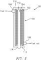
- the passive fuel additives dosing system 28 generally includes a cartridge 100, a membrane-based contactor 102 within the cartridge 100, and an additive 104 within the membrane-based contactor 102.
- the cartridge 100 includes a fuel inlet 106 and a fuel outlet 108 for communication with the fuel subsystem 30.
- the membrane-based contactor 102 is arranged within the cartridge 100 such that, with fuel in the cartridge 100, a fuel contact area with the membrane-based contactor 102 is dependent on a fuel flow rate to passively dispense a proportional amount of the additive 104 into the fuel.
- the membrane-based contactor 102 is sized and oriented within the cartridge 100 to facilitate metering of the fuel contact area with the membrane-based contactor 102 in relation to the fuel flow rate to passively dispense the additive 104.
- the fuel outlet 108 is arranged with respect to the fuel inlet 106 to facilitate metering of the fuel contact area.
- the fuel inlet 106 can be located adjacent a top 110 of the cartridge 100 and the fuel outlet 108 adjacent to a bottom 112 of the cartridge 100. This facilitates draining of the membrane-based contactor 102 once fuel flow has stopped such that osmotic pressure will not continue to drive additives into the fuel which may otherwise result in large concentrations of additives in the remaining volume of fuel. It should be appreciated that relative positional terms such as "top” and "bottom” are with respect to a normal operational attitude of the vehicle such as level flight.
- the membrane-based contactor 102 may include a non-porous or a porous membrane.
- a non-porous membrane may be a reverse selective membrane to permeate large molecules over smaller ones, based on differences in solubility rather than diffusivity.
- Suitable membranes include silicone rubbers, poly-methyl pentyl, and poly-trimethyl-silyl-propyl, and other such reverse selective types.
- Typical polymer non-porous membranes would be unsuitable for this application as membranes such as those typically used for aircraft fuel tank inerting (based on polyimides, polysulfones or polycarbonates) would result in very low permeance of the large molecules comprising the fuel additives package as well as membranes such as those used for fuel stabilization, which are inherently oleophobic (fuel and oil repellent).
- a porous membrane may comprise an oleophobic layer overcoating the outer diameter of a nanoporous polymer film to provide a barrier that facilitates prevention of the fuel from entering into the bore of each hollow fiber while the additives can exit therefrom.
- the porous membrane may have a thickness between about 50 nanometers and about 4 microns with pores of an average pore diameter less than or equal to 0.06 microns.
- the membrane-based contactor 102 may be formed as a bundle of hollow fibers, in which a bore of each fiber contains the additive in a solution, suspension, or emulsion form.
- the relatively large surface area afforded by hollow fibers facilitates effective release of the additive when the flow rate is high.
- the outside surface of each hollow fiber of the bundle of hollow fibers is wetted by the fuel that enters the cartridge 100 from the fuel inlet 106 and exits from the fuel outlet 108.
- Each hollow fiber may include a porous support and a non-porous or porous membrane on an outer diameter of the porous support.
- Another form of the membrane-based contactor 102 may be a flat sheet configuration ( FIG. 3 ), which falls outside the wording of the claims.
- FIG. 4 Other forms, which can include the bundle of hollow fibers, include a spiral-wound configuration ( FIG. 4 ), or plate-and-frame configuration ( FIG. 5 ).
- FIG. 5 examples include both organic (polymeric) and inorganic (e.g. ceramic) membranes.
- the additive can include anti-oxidants such as hindered phenols, metal deactivators, and dispersants that diffuse across the membrane-based contactor 102 due to the difference in osmotic pressure inside and outside of the hollow fibers.
- anti-oxidants such as hindered phenols, metal deactivators, and dispersants that diffuse across the membrane-based contactor 102 due to the difference in osmotic pressure inside and outside of the hollow fibers.
- some or all of the additive can be added as a concentrated liquid that is diluted to meet the specified application.
- the driving force for the additive to permeate the membrane-based contactor 102 is a concentration gradient (higher in the bore, lower in the fuel). Since the hollow fibers are always filled with the additive, the concentration difference between the inside (exposed to the additive) and the outside (exposed to flowing fuel) is essentially constant. Therefore, overall mass transfer is determined by the amount of membrane surface area wetted by the flowing fuel. This, in turn, is determined by the fuel flow rate and a recommended additive
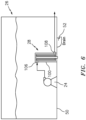
- the cartridge 100 in one embodiment, is located at a bottom 50 of the fuel tank 26 with the fuel outlet 108 adjacent to a tank fuel drain 52 in the fuel tank 26 to facilitate draining of fuel from the cartridge 100 ( FIG. 6 ).
- An additive inlet 114 FIG. 2 ) for refilling the additive is located at the bottom 112 of the cartridge 100.
- the additive inlet 114 communicates with a manifold 116 adjacent to the top 110 of the cartridge 100.
- the manifold 116 supplies additive by gravity such that the hollow fibers are always filled with the additive. Replenishment of the manifold 116 may occur over various intervals and may be conveniently performed at regular intervals as typical operators drain fuel tanks daily to avoid accumulation of water in the fuel tank. Alternatively, the entire cartridge 100 may be replaceable.
- the passive fuel additives dosing system 28 is a relatively uncomplicated, passive osmotic dispenser device that leverages osmotic pressure, as opposed to a power source with dosing properties tuned by the characteristics of the membrane-based contactor 102 as opposed to complex control systems.
Landscapes
- Engineering & Computer Science (AREA)
- Chemical & Material Sciences (AREA)
- Combustion & Propulsion (AREA)
- Mechanical Engineering (AREA)
- General Engineering & Computer Science (AREA)
- Aviation & Aerospace Engineering (AREA)
- Separation Using Semi-Permeable Membranes (AREA)
Claims (12)
- Passives Kraftstoffadditivdosierungssystem (28), umfassend:eine Kartusche (100);einen membranbasierten Kontaktgeber (102) innerhalb der Kartusche (100), der ein Bündel von Hohlfasern umfasst;einen Kraftstoffeinlass (106) zu der Kartusche (100);einen Kraftstoffauslass (108) aus der Kartusche (100); undein Additiv (104) innerhalb des membranbasierten Kontaktgebers (102), wobei der membranbasierte Kontaktgeber (102) derart in der Kartusche (100) angeordnet ist, dass mit Kraftstoff in der Kartusche (100) eine Außenfläche jeder Hohlfaser des Bündels von Hohlfasern durch den Kraftstoff benetzt wird, der durch den Kraftstoffeinlass (106) in die Kartusche (100) eintritt und durch den Kraftstoffauslass (108) austritt, und eine Kraftstoffkontaktfläche mit dem membranbasierten Kontaktgeber (102) von einer Kraftstoffdurchflussrate abhängig ist, um passiv eine proportionale Menge des Additivs in den Kraftstoff abzugeben, wobeider membranbasierte Kontaktgeber (102) mindestens eines von einem spiralförmig gewickelten Modul und einem Platten-Rahmen-Modul innerhalb der Kartusche (100) umfasst, undwobei eine Bohrung jeder der Hohlfasern das Additiv enthält.
- Passives Kraftstoffadditivdosierungssystem (28) nach Anspruch 1, wobei das Additiv in einer konzentrierten Lösungs-, Suspensions- oder Emulsionsform vorliegt.
- Passives Kraftstoffadditivdosierungssystem (28) nach Anspruch 1 oder 2, wobei der membranbasierte Kontaktgeber (102) eine poröse Membran umfasst.
- Passives Kraftstoffadditivdosierungssystem (28) nach Anspruch 3, wobei die poröse Membran eine organische oder eine anorganische Membran umfasst.
- Passives Kraftstoffadditivdosierungssystem (28) nach einem der vorhergehenden Ansprüche, wobei ein Additiveinlass (114) zum Einführen der Additive an einer Unterseite des membranbasierten Kontaktgebers (102) angeordnet ist und mit einem Verteiler (116) an einer Oberseite des membranbasierten Kontaktgebers (102) verbunden ist, derart, dass der membranbasierte Kontaktgeber (102) durch Schwerkraft kontinuierlich mit den Additiven versorgt wird.
- Passives Kraftstoffadditivdosierungssystem (28) nach einem der vorhergehenden Ansprüche, wobei der Kraftstoffeinlass (106) in Bezug auf den Kraftstoffauslass (108) derart positioniert ist, dass der Kraftstoff als Reaktion auf eine Verringerung der Kraftstoffdurchflussrate aus dem membranbasierten Kontaktgeber (102) abfließt.
- Passives Kraftstoffadditivdosierungssystem (28) nach einem der vorhergehenden Ansprüche, wobei eine Schicht des membranbasierten Kontaktgebers (102) eine Dicke zwischen 50 Nanometern und etwa 4 Mikrometern mit Poren eines durchschnittlichen Porendurchmessers von weniger als oder gleich 0,06 Mikrometern aufweist.
- Kraftstoffsystem (20) für ein Fahrzeug, umfassend:einen Kraftstofftank (26); undein passives Kraftstoffadditivdosierungssystem (28) nach einem der vorhergehenden Ansprüche innerhalb des Kraftstofftanks (26) .
- Kraftstoffsystem (20) nach Anspruch 8, wobei das passive Kraftstoffadditivdosierungssystem (28) an einer Stelle an einem Boden (50) des Kraftstofftanks (26) angeordnet ist, wobei der Kraftstoffauslass (108) zu einem Kraftstoffablass (52) im Kraftstofftank (26) benachbart ist.
- Verfahren zum Zuführen eines Additivs an Bord eines Fahrzeugs, umfassend Dosieren eines Kraftstoffs mit einem Kraftstoffadditiv aus einem passiven Kraftstoffadditivdosierungssystem (28) nach einem der Ansprüche 1 bis 7, das mit einem Kraftstofftank (26) in Verbindung steht, während des Betriebs des Fahrzeugs, wobei der membranbasierte Kontaktgeber (102) des passiven Kraftstoffadditivdosierungssystems (28) das Kraftstoffadditiv passiv proportional zu einer Kraftstoffdurchflussrate abgibt.
- Verfahren nach Anspruch 10, ferner umfassend Anordnen des passiven Kraftstoffadditivdosierungssystems (28) innerhalb des Kraftstofftanks (26).
- Verfahren nach Anspruch 10 oder 11, ferner umfassend Austauschen des passiven Kraftstoffadditivdosierungssystems (28) als eine Kartusche (100).
Applications Claiming Priority (1)
| Application Number | Priority Date | Filing Date | Title |
|---|---|---|---|
| US15/942,982 US10823072B2 (en) | 2018-04-02 | 2018-04-02 | Passive fuel additives dosing system |
Publications (2)
| Publication Number | Publication Date |
|---|---|
| EP3550125A1 EP3550125A1 (de) | 2019-10-09 |
| EP3550125B1 true EP3550125B1 (de) | 2024-02-14 |
Family
ID=66049042
Family Applications (1)
| Application Number | Title | Priority Date | Filing Date |
|---|---|---|---|
| EP19166494.5A Active EP3550125B1 (de) | 2018-04-02 | 2019-04-01 | Passives kraftstoffadditivdosierungssystem |
Country Status (2)
| Country | Link |
|---|---|
| US (1) | US10823072B2 (de) |
| EP (1) | EP3550125B1 (de) |
Families Citing this family (1)
| Publication number | Priority date | Publication date | Assignee | Title |
|---|---|---|---|---|
| US11193420B2 (en) * | 2018-11-16 | 2021-12-07 | United Technologies Corporation | System and method for monitoring fuel additives |
Family Cites Families (20)
| Publication number | Priority date | Publication date | Assignee | Title |
|---|---|---|---|---|
| US4346689A (en) | 1980-12-09 | 1982-08-31 | Neely Noah A | Controlled fuel injection system |
| US6315815B1 (en) | 1999-12-16 | 2001-11-13 | United Technologies Corporation | Membrane based fuel deoxygenator |
| US6623636B2 (en) | 2000-05-08 | 2003-09-23 | Honeywell International Inc. | Staged oil filter incorporating timed release oil conditioner |
| AUPQ984500A0 (en) | 2000-09-01 | 2000-09-28 | National Valve & Engineering Company Pty. Limited | Multi-additive injection system for aviation fuel |
| US6835218B1 (en) * | 2001-08-24 | 2004-12-28 | Dober Chemical Corp. | Fuel additive compositions |
| US6827750B2 (en) | 2001-08-24 | 2004-12-07 | Dober Chemical Corp | Controlled release additives in fuel systems |
| WO2004013484A2 (en) | 2002-08-01 | 2004-02-12 | Briggs & Stratton Corporation | Drip feed apparatus for a fuel container |
| US6709492B1 (en) | 2003-04-04 | 2004-03-23 | United Technologies Corporation | Planar membrane deoxygenator |
| US7744827B2 (en) | 2004-02-13 | 2010-06-29 | United Technologies Corporation | Catalytic treatment of fuel to impart coking resistance |
| US7431818B2 (en) | 2004-03-26 | 2008-10-07 | United Technologies Corporation | Electrochemical fuel deoxygenation system |
| US7393388B2 (en) | 2005-05-13 | 2008-07-01 | United Technologies Corporation | Spiral wound fuel stabilization unit for fuel de-oxygenation |
| US8648596B2 (en) | 2006-10-31 | 2014-02-11 | Active Spectrum, Inc. | Method of and apparatus for analysis of the composition of a sample by electron spin resonance (ESR) spectrometry employing carrier suppression |
| US8210826B2 (en) | 2006-04-15 | 2012-07-03 | William Freeman | Controlled liquid injection and blending apparatus |
| US7950216B2 (en) | 2007-01-30 | 2011-05-31 | Pratt & Whitney Canada Corp. | Gas turbine engine fuel control system |
| US8702995B2 (en) | 2008-05-27 | 2014-04-22 | Dober Chemical Corp. | Controlled release of microbiocides |
| US8468982B2 (en) | 2009-03-09 | 2013-06-25 | GM Global Technology Operations LLC | Systems and methods for dispensing oil and fuel additives |
| US20100242490A1 (en) | 2009-03-31 | 2010-09-30 | General Electric Company | Additive delivery systems and methods |
| FR2971016B1 (fr) | 2011-02-02 | 2015-08-07 | Filtrauto | Dispositif de distribution d'un additif |
| US9458761B2 (en) | 2011-09-07 | 2016-10-04 | Afton Chemical Corporation | Airborne engine additive delivery system |
| KR101376464B1 (ko) | 2012-11-28 | 2014-03-19 | (주) 유니크코리아엔아이 | 디젤선박 연비향상을 위한 첨가제 농도측정용 센서모듈 |
-
2018
- 2018-04-02 US US15/942,982 patent/US10823072B2/en active Active
-
2019
- 2019-04-01 EP EP19166494.5A patent/EP3550125B1/de active Active
Also Published As
| Publication number | Publication date |
|---|---|
| EP3550125A1 (de) | 2019-10-09 |
| US20190301368A1 (en) | 2019-10-03 |
| US10823072B2 (en) | 2020-11-03 |
Similar Documents
| Publication | Publication Date | Title |
|---|---|---|
| EP3034409B1 (de) | Flugzeugtreibstoffsauerstoffreduzierungssystem | |
| US11879388B2 (en) | System and method for monitoring fuel additives | |
| US4790941A (en) | Fluid decontamination system | |
| US10478780B2 (en) | Separating device for separating at least one undesired fluid from a liquid, membrane of a separating device, filter, filter element, and liquid system | |
| US4850498A (en) | Fluid decontamination system | |
| EP3095498A1 (de) | Flugzeugkraftstoffsystem mit fliehkraftabscheider | |
| EP3550125B1 (de) | Passives kraftstoffadditivdosierungssystem | |
| US10688440B2 (en) | Fuel fractioning unit for inert gas generating system | |
| US4844804A (en) | Fluid decontamination system | |
| EP2570469A1 (de) | Brennstofffraktionierung mittels Membrandestillation | |
| EP2784299A1 (de) | Dieselkraftstoffstabilisierung für verbesserte Verbrennung | |
| US20180274505A1 (en) | Fuel filter system with water emulsifier | |
| RU2388927C2 (ru) | Транспортное средство | |
| US20180318730A1 (en) | Vacuum systems for degassing of liquid hydrocarbon fuels | |
| US20190022557A1 (en) | Fuel tank de-oxygenation system | |
| JP7609855B2 (ja) | 噴射器堆積物を低減するためのプロセス | |
| Ayrancı | Design and performance evaluation of a fuel filter | |
| EP3539880B1 (de) | Kavitationsminderung in kraftstofftankinertisierungssystemen mit katalytischer oxidation | |
| EP1538330B1 (de) | Selbstentlüftendes Kraftstoffversorgungssystem für einen Dieselmotor mit einer durch Schwerkraft erstbefüllten Förderpumpe | |
| NL8300403A (nl) | Brandstofinrichting voor scheepsdieselmotoren. | |
| US20240253014A1 (en) | Oxygen reduction system for a hydrocarbon fluid | |
| US20190022558A1 (en) | Fuel tank de-oxygenation system | |
| CN119982270A (zh) | 一种船用甲醇燃料供给系统 | |
| WO2016174299A1 (en) | A fuel supply arrangement for an internal combustion engine and a method of filtering fuel in a fuel supply arrangement of an internal combustion engine | |
| WO2020132656A1 (en) | Composite hollow fiber membranes for jet fuel de-oxygenation |
Legal Events
| Date | Code | Title | Description |
|---|---|---|---|
| PUAI | Public reference made under article 153(3) epc to a published international application that has entered the european phase |
Free format text: ORIGINAL CODE: 0009012 |
|
| STAA | Information on the status of an ep patent application or granted ep patent |
Free format text: STATUS: THE APPLICATION HAS BEEN PUBLISHED |
|
| AK | Designated contracting states |
Kind code of ref document: A1 Designated state(s): AL AT BE BG CH CY CZ DE DK EE ES FI FR GB GR HR HU IE IS IT LI LT LU LV MC MK MT NL NO PL PT RO RS SE SI SK SM TR |
|
| AX | Request for extension of the european patent |
Extension state: BA ME |
|
| STAA | Information on the status of an ep patent application or granted ep patent |
Free format text: STATUS: REQUEST FOR EXAMINATION WAS MADE |
|
| 17P | Request for examination filed |
Effective date: 20200406 |
|
| RBV | Designated contracting states (corrected) |
Designated state(s): AL AT BE BG CH CY CZ DE DK EE ES FI FR GB GR HR HU IE IS IT LI LT LU LV MC MK MT NL NO PL PT RO RS SE SI SK SM TR |
|
| RAP1 | Party data changed (applicant data changed or rights of an application transferred) |
Owner name: RAYTHEON TECHNOLOGIES CORPORATION |
|
| STAA | Information on the status of an ep patent application or granted ep patent |
Free format text: STATUS: EXAMINATION IS IN PROGRESS |
|
| 17Q | First examination report despatched |
Effective date: 20210722 |
|
| GRAP | Despatch of communication of intention to grant a patent |
Free format text: ORIGINAL CODE: EPIDOSNIGR1 |
|
| STAA | Information on the status of an ep patent application or granted ep patent |
Free format text: STATUS: GRANT OF PATENT IS INTENDED |
|
| INTG | Intention to grant announced |
Effective date: 20230908 |
|
| RAP3 | Party data changed (applicant data changed or rights of an application transferred) |
Owner name: RTX CORPORATION |
|
| GRAS | Grant fee paid |
Free format text: ORIGINAL CODE: EPIDOSNIGR3 |
|
| GRAA | (expected) grant |
Free format text: ORIGINAL CODE: 0009210 |
|
| STAA | Information on the status of an ep patent application or granted ep patent |
Free format text: STATUS: THE PATENT HAS BEEN GRANTED |
|
| AK | Designated contracting states |
Kind code of ref document: B1 Designated state(s): AL AT BE BG CH CY CZ DE DK EE ES FI FR GB GR HR HU IE IS IT LI LT LU LV MC MK MT NL NO PL PT RO RS SE SI SK SM TR |
|
| REG | Reference to a national code |
Ref country code: GB Ref legal event code: FG4D |
|
| REG | Reference to a national code |
Ref country code: CH Ref legal event code: EP |
|
| REG | Reference to a national code |
Ref country code: DE Ref legal event code: R096 Ref document number: 602019046390 Country of ref document: DE |
|
| REG | Reference to a national code |
Ref country code: IE Ref legal event code: FG4D |
|
| REG | Reference to a national code |
Ref country code: LT Ref legal event code: MG9D |
|
| REG | Reference to a national code |
Ref country code: NL Ref legal event code: MP Effective date: 20240214 |
|
| PG25 | Lapsed in a contracting state [announced via postgrant information from national office to epo] |
Ref country code: IS Free format text: LAPSE BECAUSE OF FAILURE TO SUBMIT A TRANSLATION OF THE DESCRIPTION OR TO PAY THE FEE WITHIN THE PRESCRIBED TIME-LIMIT Effective date: 20240614 |
|
| PG25 | Lapsed in a contracting state [announced via postgrant information from national office to epo] |
Ref country code: LT Free format text: LAPSE BECAUSE OF FAILURE TO SUBMIT A TRANSLATION OF THE DESCRIPTION OR TO PAY THE FEE WITHIN THE PRESCRIBED TIME-LIMIT Effective date: 20240214 |
|
| PG25 | Lapsed in a contracting state [announced via postgrant information from national office to epo] |
Ref country code: GR Free format text: LAPSE BECAUSE OF FAILURE TO SUBMIT A TRANSLATION OF THE DESCRIPTION OR TO PAY THE FEE WITHIN THE PRESCRIBED TIME-LIMIT Effective date: 20240515 |
|
| REG | Reference to a national code |
Ref country code: AT Ref legal event code: MK05 Ref document number: 1657194 Country of ref document: AT Kind code of ref document: T Effective date: 20240214 |
|
| PG25 | Lapsed in a contracting state [announced via postgrant information from national office to epo] |
Ref country code: HR Free format text: LAPSE BECAUSE OF FAILURE TO SUBMIT A TRANSLATION OF THE DESCRIPTION OR TO PAY THE FEE WITHIN THE PRESCRIBED TIME-LIMIT Effective date: 20240214 Ref country code: NL Free format text: LAPSE BECAUSE OF FAILURE TO SUBMIT A TRANSLATION OF THE DESCRIPTION OR TO PAY THE FEE WITHIN THE PRESCRIBED TIME-LIMIT Effective date: 20240214 Ref country code: RS Free format text: LAPSE BECAUSE OF FAILURE TO SUBMIT A TRANSLATION OF THE DESCRIPTION OR TO PAY THE FEE WITHIN THE PRESCRIBED TIME-LIMIT Effective date: 20240514 |
|
| PG25 | Lapsed in a contracting state [announced via postgrant information from national office to epo] |
Ref country code: ES Free format text: LAPSE BECAUSE OF FAILURE TO SUBMIT A TRANSLATION OF THE DESCRIPTION OR TO PAY THE FEE WITHIN THE PRESCRIBED TIME-LIMIT Effective date: 20240214 |
|
| PG25 | Lapsed in a contracting state [announced via postgrant information from national office to epo] |
Ref country code: AT Free format text: LAPSE BECAUSE OF FAILURE TO SUBMIT A TRANSLATION OF THE DESCRIPTION OR TO PAY THE FEE WITHIN THE PRESCRIBED TIME-LIMIT Effective date: 20240214 |
|
| PG25 | Lapsed in a contracting state [announced via postgrant information from national office to epo] |
Ref country code: RS Free format text: LAPSE BECAUSE OF FAILURE TO SUBMIT A TRANSLATION OF THE DESCRIPTION OR TO PAY THE FEE WITHIN THE PRESCRIBED TIME-LIMIT Effective date: 20240514 Ref country code: NO Free format text: LAPSE BECAUSE OF FAILURE TO SUBMIT A TRANSLATION OF THE DESCRIPTION OR TO PAY THE FEE WITHIN THE PRESCRIBED TIME-LIMIT Effective date: 20240514 Ref country code: NL Free format text: LAPSE BECAUSE OF FAILURE TO SUBMIT A TRANSLATION OF THE DESCRIPTION OR TO PAY THE FEE WITHIN THE PRESCRIBED TIME-LIMIT Effective date: 20240214 Ref country code: LT Free format text: LAPSE BECAUSE OF FAILURE TO SUBMIT A TRANSLATION OF THE DESCRIPTION OR TO PAY THE FEE WITHIN THE PRESCRIBED TIME-LIMIT Effective date: 20240214 Ref country code: IS Free format text: LAPSE BECAUSE OF FAILURE TO SUBMIT A TRANSLATION OF THE DESCRIPTION OR TO PAY THE FEE WITHIN THE PRESCRIBED TIME-LIMIT Effective date: 20240614 Ref country code: HR Free format text: LAPSE BECAUSE OF FAILURE TO SUBMIT A TRANSLATION OF THE DESCRIPTION OR TO PAY THE FEE WITHIN THE PRESCRIBED TIME-LIMIT Effective date: 20240214 Ref country code: GR Free format text: LAPSE BECAUSE OF FAILURE TO SUBMIT A TRANSLATION OF THE DESCRIPTION OR TO PAY THE FEE WITHIN THE PRESCRIBED TIME-LIMIT Effective date: 20240515 Ref country code: FI Free format text: LAPSE BECAUSE OF FAILURE TO SUBMIT A TRANSLATION OF THE DESCRIPTION OR TO PAY THE FEE WITHIN THE PRESCRIBED TIME-LIMIT Effective date: 20240214 Ref country code: ES Free format text: LAPSE BECAUSE OF FAILURE TO SUBMIT A TRANSLATION OF THE DESCRIPTION OR TO PAY THE FEE WITHIN THE PRESCRIBED TIME-LIMIT Effective date: 20240214 Ref country code: BG Free format text: LAPSE BECAUSE OF FAILURE TO SUBMIT A TRANSLATION OF THE DESCRIPTION OR TO PAY THE FEE WITHIN THE PRESCRIBED TIME-LIMIT Effective date: 20240214 Ref country code: AT Free format text: LAPSE BECAUSE OF FAILURE TO SUBMIT A TRANSLATION OF THE DESCRIPTION OR TO PAY THE FEE WITHIN THE PRESCRIBED TIME-LIMIT Effective date: 20240214 |
|
| PG25 | Lapsed in a contracting state [announced via postgrant information from national office to epo] |
Ref country code: PT Free format text: LAPSE BECAUSE OF FAILURE TO SUBMIT A TRANSLATION OF THE DESCRIPTION OR TO PAY THE FEE WITHIN THE PRESCRIBED TIME-LIMIT Effective date: 20240614 Ref country code: PL Free format text: LAPSE BECAUSE OF FAILURE TO SUBMIT A TRANSLATION OF THE DESCRIPTION OR TO PAY THE FEE WITHIN THE PRESCRIBED TIME-LIMIT Effective date: 20240214 |
|
| PG25 | Lapsed in a contracting state [announced via postgrant information from national office to epo] |
Ref country code: SE Free format text: LAPSE BECAUSE OF FAILURE TO SUBMIT A TRANSLATION OF THE DESCRIPTION OR TO PAY THE FEE WITHIN THE PRESCRIBED TIME-LIMIT Effective date: 20240214 Ref country code: PT Free format text: LAPSE BECAUSE OF FAILURE TO SUBMIT A TRANSLATION OF THE DESCRIPTION OR TO PAY THE FEE WITHIN THE PRESCRIBED TIME-LIMIT Effective date: 20240614 Ref country code: PL Free format text: LAPSE BECAUSE OF FAILURE TO SUBMIT A TRANSLATION OF THE DESCRIPTION OR TO PAY THE FEE WITHIN THE PRESCRIBED TIME-LIMIT Effective date: 20240214 Ref country code: LV Free format text: LAPSE BECAUSE OF FAILURE TO SUBMIT A TRANSLATION OF THE DESCRIPTION OR TO PAY THE FEE WITHIN THE PRESCRIBED TIME-LIMIT Effective date: 20240214 |
|
| PG25 | Lapsed in a contracting state [announced via postgrant information from national office to epo] |
Ref country code: DK Free format text: LAPSE BECAUSE OF FAILURE TO SUBMIT A TRANSLATION OF THE DESCRIPTION OR TO PAY THE FEE WITHIN THE PRESCRIBED TIME-LIMIT Effective date: 20240214 |
|
| PG25 | Lapsed in a contracting state [announced via postgrant information from national office to epo] |
Ref country code: SM Free format text: LAPSE BECAUSE OF FAILURE TO SUBMIT A TRANSLATION OF THE DESCRIPTION OR TO PAY THE FEE WITHIN THE PRESCRIBED TIME-LIMIT Effective date: 20240214 |
|
| PG25 | Lapsed in a contracting state [announced via postgrant information from national office to epo] |
Ref country code: EE Free format text: LAPSE BECAUSE OF FAILURE TO SUBMIT A TRANSLATION OF THE DESCRIPTION OR TO PAY THE FEE WITHIN THE PRESCRIBED TIME-LIMIT Effective date: 20240214 Ref country code: CZ Free format text: LAPSE BECAUSE OF FAILURE TO SUBMIT A TRANSLATION OF THE DESCRIPTION OR TO PAY THE FEE WITHIN THE PRESCRIBED TIME-LIMIT Effective date: 20240214 |
|
| PG25 | Lapsed in a contracting state [announced via postgrant information from national office to epo] |
Ref country code: SK Free format text: LAPSE BECAUSE OF FAILURE TO SUBMIT A TRANSLATION OF THE DESCRIPTION OR TO PAY THE FEE WITHIN THE PRESCRIBED TIME-LIMIT Effective date: 20240214 |
|
| PG25 | Lapsed in a contracting state [announced via postgrant information from national office to epo] |
Ref country code: SM Free format text: LAPSE BECAUSE OF FAILURE TO SUBMIT A TRANSLATION OF THE DESCRIPTION OR TO PAY THE FEE WITHIN THE PRESCRIBED TIME-LIMIT Effective date: 20240214 Ref country code: SK Free format text: LAPSE BECAUSE OF FAILURE TO SUBMIT A TRANSLATION OF THE DESCRIPTION OR TO PAY THE FEE WITHIN THE PRESCRIBED TIME-LIMIT Effective date: 20240214 Ref country code: RO Free format text: LAPSE BECAUSE OF FAILURE TO SUBMIT A TRANSLATION OF THE DESCRIPTION OR TO PAY THE FEE WITHIN THE PRESCRIBED TIME-LIMIT Effective date: 20240214 Ref country code: EE Free format text: LAPSE BECAUSE OF FAILURE TO SUBMIT A TRANSLATION OF THE DESCRIPTION OR TO PAY THE FEE WITHIN THE PRESCRIBED TIME-LIMIT Effective date: 20240214 Ref country code: DK Free format text: LAPSE BECAUSE OF FAILURE TO SUBMIT A TRANSLATION OF THE DESCRIPTION OR TO PAY THE FEE WITHIN THE PRESCRIBED TIME-LIMIT Effective date: 20240214 Ref country code: CZ Free format text: LAPSE BECAUSE OF FAILURE TO SUBMIT A TRANSLATION OF THE DESCRIPTION OR TO PAY THE FEE WITHIN THE PRESCRIBED TIME-LIMIT Effective date: 20240214 |
|
| REG | Reference to a national code |
Ref country code: DE Ref legal event code: R097 Ref document number: 602019046390 Country of ref document: DE |
|
| PG25 | Lapsed in a contracting state [announced via postgrant information from national office to epo] |
Ref country code: MC Free format text: LAPSE BECAUSE OF FAILURE TO SUBMIT A TRANSLATION OF THE DESCRIPTION OR TO PAY THE FEE WITHIN THE PRESCRIBED TIME-LIMIT Effective date: 20240214 |
|
| PG25 | Lapsed in a contracting state [announced via postgrant information from national office to epo] |
Ref country code: MC Free format text: LAPSE BECAUSE OF FAILURE TO SUBMIT A TRANSLATION OF THE DESCRIPTION OR TO PAY THE FEE WITHIN THE PRESCRIBED TIME-LIMIT Effective date: 20240214 |
|
| REG | Reference to a national code |
Ref country code: CH Ref legal event code: PL |
|
| PG25 | Lapsed in a contracting state [announced via postgrant information from national office to epo] |
Ref country code: IT Free format text: LAPSE BECAUSE OF FAILURE TO SUBMIT A TRANSLATION OF THE DESCRIPTION OR TO PAY THE FEE WITHIN THE PRESCRIBED TIME-LIMIT Effective date: 20240214 |
|
| PG25 | Lapsed in a contracting state [announced via postgrant information from national office to epo] |
Ref country code: LU Free format text: LAPSE BECAUSE OF NON-PAYMENT OF DUE FEES Effective date: 20240401 |
|
| PLBE | No opposition filed within time limit |
Free format text: ORIGINAL CODE: 0009261 |
|
| STAA | Information on the status of an ep patent application or granted ep patent |
Free format text: STATUS: NO OPPOSITION FILED WITHIN TIME LIMIT |
|
| REG | Reference to a national code |
Ref country code: BE Ref legal event code: MM Effective date: 20240430 |
|
| PG25 | Lapsed in a contracting state [announced via postgrant information from national office to epo] |
Ref country code: LU Free format text: LAPSE BECAUSE OF NON-PAYMENT OF DUE FEES Effective date: 20240401 Ref country code: IT Free format text: LAPSE BECAUSE OF FAILURE TO SUBMIT A TRANSLATION OF THE DESCRIPTION OR TO PAY THE FEE WITHIN THE PRESCRIBED TIME-LIMIT Effective date: 20240214 |
|
| PG25 | Lapsed in a contracting state [announced via postgrant information from national office to epo] |
Ref country code: BE Free format text: LAPSE BECAUSE OF NON-PAYMENT OF DUE FEES Effective date: 20240430 |
|
| 26N | No opposition filed |
Effective date: 20241115 |
|
| PG25 | Lapsed in a contracting state [announced via postgrant information from national office to epo] |
Ref country code: BE Free format text: LAPSE BECAUSE OF NON-PAYMENT OF DUE FEES Effective date: 20240430 Ref country code: CH Free format text: LAPSE BECAUSE OF NON-PAYMENT OF DUE FEES Effective date: 20240430 |
|
| PG25 | Lapsed in a contracting state [announced via postgrant information from national office to epo] |
Ref country code: IE Free format text: LAPSE BECAUSE OF NON-PAYMENT OF DUE FEES Effective date: 20240401 |
|
| PG25 | Lapsed in a contracting state [announced via postgrant information from national office to epo] |
Ref country code: SI Free format text: LAPSE BECAUSE OF FAILURE TO SUBMIT A TRANSLATION OF THE DESCRIPTION OR TO PAY THE FEE WITHIN THE PRESCRIBED TIME-LIMIT Effective date: 20240214 |
|
| PGFP | Annual fee paid to national office [announced via postgrant information from national office to epo] |
Ref country code: DE Payment date: 20250319 Year of fee payment: 7 |
|
| PG25 | Lapsed in a contracting state [announced via postgrant information from national office to epo] |
Ref country code: CY Free format text: LAPSE BECAUSE OF FAILURE TO SUBMIT A TRANSLATION OF THE DESCRIPTION OR TO PAY THE FEE WITHIN THE PRESCRIBED TIME-LIMIT; INVALID AB INITIO Effective date: 20190401 |
|
| PG25 | Lapsed in a contracting state [announced via postgrant information from national office to epo] |
Ref country code: HU Free format text: LAPSE BECAUSE OF FAILURE TO SUBMIT A TRANSLATION OF THE DESCRIPTION OR TO PAY THE FEE WITHIN THE PRESCRIBED TIME-LIMIT; INVALID AB INITIO Effective date: 20190401 |
|
| PG25 | Lapsed in a contracting state [announced via postgrant information from national office to epo] |
Ref country code: TR Free format text: LAPSE BECAUSE OF FAILURE TO SUBMIT A TRANSLATION OF THE DESCRIPTION OR TO PAY THE FEE WITHIN THE PRESCRIBED TIME-LIMIT Effective date: 20240214 |
|
| PGFP | Annual fee paid to national office [announced via postgrant information from national office to epo] |
Ref country code: GB Payment date: 20260319 Year of fee payment: 8 |
|
| PGFP | Annual fee paid to national office [announced via postgrant information from national office to epo] |
Ref country code: FR Payment date: 20260320 Year of fee payment: 8 |