EP3550114A1 - Gaswegkanal für einen gasturbinenmotor - Google Patents
Gaswegkanal für einen gasturbinenmotor Download PDFInfo
- Publication number
- EP3550114A1 EP3550114A1 EP19167167.6A EP19167167A EP3550114A1 EP 3550114 A1 EP3550114 A1 EP 3550114A1 EP 19167167 A EP19167167 A EP 19167167A EP 3550114 A1 EP3550114 A1 EP 3550114A1
- Authority
- EP
- European Patent Office
- Prior art keywords
- pivot point
- gas path
- shroud
- longitudinal axis
- spherical surface
- Prior art date
- Legal status (The legal status is an assumption and is not a legal conclusion. Google has not performed a legal analysis and makes no representation as to the accuracy of the status listed.)
- Withdrawn
Links
- 238000011144 upstream manufacturing Methods 0.000 claims description 7
- 230000000295 complement effect Effects 0.000 claims 1
- 239000007789 gas Substances 0.000 description 41
- 239000003570 air Substances 0.000 description 4
- 239000000567 combustion gas Substances 0.000 description 2
- 238000012986 modification Methods 0.000 description 2
- 230000004048 modification Effects 0.000 description 2
- 239000012080 ambient air Substances 0.000 description 1
- 239000000446 fuel Substances 0.000 description 1
- 238000004519 manufacturing process Methods 0.000 description 1
Images


Classifications
-
- F—MECHANICAL ENGINEERING; LIGHTING; HEATING; WEAPONS; BLASTING
- F01—MACHINES OR ENGINES IN GENERAL; ENGINE PLANTS IN GENERAL; STEAM ENGINES
- F01D—NON-POSITIVE DISPLACEMENT MACHINES OR ENGINES, e.g. STEAM TURBINES
- F01D17/00—Regulating or controlling by varying flow
- F01D17/10—Final actuators
- F01D17/12—Final actuators arranged in stator parts
- F01D17/14—Final actuators arranged in stator parts varying effective cross-sectional area of nozzles or guide conduits
- F01D17/16—Final actuators arranged in stator parts varying effective cross-sectional area of nozzles or guide conduits by means of nozzle vanes
- F01D17/162—Final actuators arranged in stator parts varying effective cross-sectional area of nozzles or guide conduits by means of nozzle vanes for axial flow, i.e. the vanes turning around axes which are essentially perpendicular to the rotor centre line
-
- F—MECHANICAL ENGINEERING; LIGHTING; HEATING; WEAPONS; BLASTING
- F04—POSITIVE - DISPLACEMENT MACHINES FOR LIQUIDS; PUMPS FOR LIQUIDS OR ELASTIC FLUIDS
- F04D—NON-POSITIVE-DISPLACEMENT PUMPS
- F04D29/00—Details, component parts, or accessories
- F04D29/40—Casings; Connections of working fluid
- F04D29/52—Casings; Connections of working fluid for axial pumps
- F04D29/54—Fluid-guiding means, e.g. diffusers
- F04D29/541—Specially adapted for elastic fluid pumps
- F04D29/545—Ducts
- F04D29/547—Ducts having a special shape in order to influence fluid flow
-
- F—MECHANICAL ENGINEERING; LIGHTING; HEATING; WEAPONS; BLASTING
- F01—MACHINES OR ENGINES IN GENERAL; ENGINE PLANTS IN GENERAL; STEAM ENGINES
- F01D—NON-POSITIVE DISPLACEMENT MACHINES OR ENGINES, e.g. STEAM TURBINES
- F01D9/00—Stators
- F01D9/02—Nozzles; Nozzle boxes; Stator blades; Guide conduits, e.g. individual nozzles
- F01D9/04—Nozzles; Nozzle boxes; Stator blades; Guide conduits, e.g. individual nozzles forming ring or sector
- F01D9/041—Nozzles; Nozzle boxes; Stator blades; Guide conduits, e.g. individual nozzles forming ring or sector using blades
-
- F—MECHANICAL ENGINEERING; LIGHTING; HEATING; WEAPONS; BLASTING
- F04—POSITIVE - DISPLACEMENT MACHINES FOR LIQUIDS; PUMPS FOR LIQUIDS OR ELASTIC FLUIDS
- F04D—NON-POSITIVE-DISPLACEMENT PUMPS
- F04D29/00—Details, component parts, or accessories
- F04D29/40—Casings; Connections of working fluid
- F04D29/52—Casings; Connections of working fluid for axial pumps
- F04D29/54—Fluid-guiding means, e.g. diffusers
- F04D29/56—Fluid-guiding means, e.g. diffusers adjustable
-
- F—MECHANICAL ENGINEERING; LIGHTING; HEATING; WEAPONS; BLASTING
- F05—INDEXING SCHEMES RELATING TO ENGINES OR PUMPS IN VARIOUS SUBCLASSES OF CLASSES F01-F04
- F05D—INDEXING SCHEME FOR ASPECTS RELATING TO NON-POSITIVE-DISPLACEMENT MACHINES OR ENGINES, GAS-TURBINES OR JET-PROPULSION PLANTS
- F05D2220/00—Application
- F05D2220/30—Application in turbines
- F05D2220/32—Application in turbines in gas turbines
- F05D2220/321—Application in turbines in gas turbines for a special turbine stage
- F05D2220/3216—Application in turbines in gas turbines for a special turbine stage for a special compressor stage
-
- F—MECHANICAL ENGINEERING; LIGHTING; HEATING; WEAPONS; BLASTING
- F05—INDEXING SCHEMES RELATING TO ENGINES OR PUMPS IN VARIOUS SUBCLASSES OF CLASSES F01-F04
- F05D—INDEXING SCHEME FOR ASPECTS RELATING TO NON-POSITIVE-DISPLACEMENT MACHINES OR ENGINES, GAS-TURBINES OR JET-PROPULSION PLANTS
- F05D2240/00—Components
- F05D2240/10—Stators
- F05D2240/12—Fluid guiding means, e.g. vanes
- F05D2240/127—Vortex generators, turbulators, or the like, for mixing
-
- F—MECHANICAL ENGINEERING; LIGHTING; HEATING; WEAPONS; BLASTING
- F05—INDEXING SCHEMES RELATING TO ENGINES OR PUMPS IN VARIOUS SUBCLASSES OF CLASSES F01-F04
- F05D—INDEXING SCHEME FOR ASPECTS RELATING TO NON-POSITIVE-DISPLACEMENT MACHINES OR ENGINES, GAS-TURBINES OR JET-PROPULSION PLANTS
- F05D2250/00—Geometry
- F05D2250/20—Three-dimensional
- F05D2250/24—Three-dimensional ellipsoidal
- F05D2250/241—Three-dimensional ellipsoidal spherical
Definitions
- variable-pitch vanes and, more particularly, to a gas path duct for surrounding such variable vanes.
- Variable pitch-vanes such as variable inlet guide vanes (VIGVs) extend between inner and outer shrouds of a gas path, such as is found in the inlet duct of a gas turbine engine.
- the vanes can be variably positioned in the duct by pivoting about a span axis, to affect the swirl in the duct. As each vane pivots about its span axis, a clearance gap between the vane's end and the shrouds can vary, which can lead to unwanted vane tip aerodynamic losses.
- a gas path duct for a gas turbine engine, the gas path duct comprising an annular gas path defined around a longitudinal axis between an inner shroud and an outer shroud spaced radially outward from the inner shroud relative to the longitudinal axis, the annular gas path adapted to receive therein a variable-pitch vane mounted between the inner and outer shrouds, the variable-pitch vane adapted to be pivotable about a pivot axis extending across the gas path between an outer pivot point and an inner pivot point, the outer pivot point located along the outer shroud and the inner pivot point located along the inner shroud; and a portion of at least one of the inner and outer shrouds defining a spherical surface having a concave shape facing the longitudinal axis and extending away from a corresponding one of the inner and outer pivot points along a corresponding one of the inner and outer shrouds, the spherical surface having a center positioned on the pivot axi
- a gas turbine engine comprising an annular gas path defined around a longitudinal axis between an inner shroud and an outer shroud spaced radially outward from the inner shroud relative to the longitudinal axis; a plurality of variable-pitch vanes extending between the inner and outer shrouds, each one of the plurality of variable-pitch vanes pivotable about a pivot axis extending across the gas path between an outer pivot point located along the outer shroud and an inner pivot point located along the inner shroud, the plurality of variable-pitch vanes pivoting through a full range of angular positions between an open position and a closed position; and at least one of the inner and outer shrouds has a portion defining a spherical surface with a concave shape facing the longitudinal axis and extending away from a corresponding one of the inner and outer pivot points along a corresponding one of the inner and outer shrouds, the spherical surface having a center positioned on
- variable vane assembly for a gas turbine engine comprising an annular gas path defined around a longitudinal axis between an inner shroud and an outer shroud spaced radially outward from the inner shroud relative to the longitudinal axis; a plurality of variable-pitch vanes extending between the inner and outer shrouds, each one of the plurality of variable-pitch vanes pivotable about a pivot axis extending across the gas path between an outer pivot point located along the outer shroud and an inner pivot point located along the inner shroud, the plurality of variable-pitch vanes pivoting through a full range of angular positions between an open position and a closed position; and at least one of the inner and outer shrouds has a portion defining a spherical surface with a concave shape facing the longitudinal axis and extending away from a corresponding one of the inner and outer pivot points along a corresponding one of the inner and outer shrouds, the spher
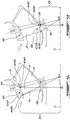
- Fig. 1 illustrates a gas turbine engine 10 of a type preferably provided for use in subsonic flight, generally comprising in serial flow communication along a longitudinal axis 11 a fan 12 through which ambient air is propelled, a compressor section 14 for pressurizing the air, a combustor 16 in which the compressed air is mixed with fuel and ignited for generating an annular stream of hot combustion gases, and a turbine section 18 for extracting energy from the combustion gases.
- a gas path duct 20 of the engine 10 is shown defining an annular gas path 22.
- the gas path duct 20 can direct an air flow into a compressor stage of the compressor section 14 through the gas path 22.
- the gas path duct 20 includes an outer shroud 24 and an inner shroud 26 extending along the longitudinal axis 11.
- the outer shroud 24 is spaced radially outward from the inner shroud 26 relative to the longitudinal axis 11.
- the outer shroud 24 defines a radially outer boundary of the gas path 22 and the inner shroud 26 defines a radially inner boundary of the gas path 22.
- the gas path duct 24 can refer to any other suitable ducts of the gas turbine engine 10.
- the compressor section 14 may include a plurality of variable-pitch vanes 28 disposed in the gas path duct 20.
- the variable-pitch vanes 28 may be variable inlet guide vanes (VIGVs).
- VGVs variable inlet guide vanes
- the variable-pitch vane 28 will be described below as an inlet guide vane 28, it is understood that variable-pitch vanes may be disposed in any suitable section of the gas turbine engine 10, and not necessarily at an inlet of the compressor or turbine stage.
- the inlet guide vanes 28 are variable between multiple positions. That is, the inlet guide vanes 28 may rotate about a pivot axis 30 between a closed position and an open position.
- the open position may refer to an angular position of zero degree (0 degree) relative to the longitudinal axis 11
- the closed position may refer to an angular position of sixty degrees (60 degrees). It is understood that other reference angular positions may be used to define the open and closed positions.
- a full range of angular positions can be defined between the open and closed positions as shown.
- the inlet guide vane 28 may be positioned at any angular position thereof.
- the full range of angular positions may extend to a range of 180 degrees.
- the pivot axis 30 extends across the gas path 22 between the outer and inner shrouds 24, 26 and may be inclined by a specific angle 32 with respect to a plane perpendicular P to the longitudinal axis 11.
- the inlet guide vane 28 rotates about the pivot axis 30 between an outer pivot point 34A and an inner pivot point 34B.
- the outer pivot point 34A is located at an intersection of the pivot axis 30 and the outer shroud 24 and the inner pivot point 34B is located at an intersection of the pivot axis 30 and the inner shroud 26.
- An upper end 28A of the inlet guide vane 28 is radially located toward the outer pivot point 34A and a lower end 28B of the inlet guide vane 28 is radially located toward the inner pivot point 34B.
- a radial clearance gap is defined on each side of the inlet guide vane 28.
- One clearance gap is defined between the upper end 28A and the outer shroud 24 and another clearance gap is defined between the lower end 28B and the inner shroud 26.
- the inlet guide vane 28 extends along a span between the lower end 28B and the upper end 28A and extends chordally between a leading edge 36 and a trailing edge 38.
- the pivot axis 30 may extend through cross-sectional centers of pressure of the inlet guide vane 28 along the span between the outer and inner pivot points 34A, 34B.
- one or more portions of the gas path duct 20 may define a spherical surface 40 opposite the inlet guide vane 28 to minimizes variations of the clearance gap during the pivoting of the inlet guide vane 28.
- the term "spherical surface" is intended to refer to a portion of a sphere and may differ slightly from being a perfectly spherical surface.
- the outer shroud 24, the inner shroud 26, or both may define a corresponding spherical surface 40 opposite the upper end 28A, the lower end 28B, or both.
- one spherical surface 40A may be disposed opposite the upper end 28A and another spherical surface 40B may be disposed opposite the lower end 28B.
- the spherical surface 40 has a concave shape facing the longitudinal axis 11.
- the spherical surface 40 may have a shape that is complimentary in shape and in registry with one of the ends 28A, 28B of the inlet guide vane 28, or both, such that the radial clearance gap remains at least substantially constant through the full range of angular positions. It is understood that manufacturing tolerances, thermal expansions, and the like may affect the variation of the clearance gap.
- the constant variation of the clearance gap is intended to refer to the variation caused by the general shape of gas path ducts.
- the spherical surface 40A of the outer shroud 24 extends away from the outer pivot point 34A along the outer shroud 24 ( Fig. 3A ) and the spherical surface 40B of the inner shroud 26 extends away from the inner pivot point 34B along the inner shroud 26 ( Fig. 3B ).
- the corresponding spherical surface 40 may extend downstream of the pivot axis 30, upstream of the pivot axis 30, or both, relative to a direction of the air flow, or gas flow, through the gas path 22.
- the spherical surface 40 has an arc 42 spanning from the pivot point 34 to a boundary point 44 downstream of the pivot point 34.
- the downstream boundary point 44 at least surrounds an end part (where the end part may be a radially inner part or a radially outer part) of the trailing edge 38.
- the spherical surface 40 may have an arc 46 spanning from the pivot point 34 to a boundary point 48 upstream of the pivot point 34.
- the upstream boundary point 48 at least surrounds an end part (where the end part may be a radially outer part or a radially inner part) of the leading edge 36.
- the spherical surface 40 may also have the arc 42 downstream of the pivot point 34 and the arc 46 upstream of the pivot point 34.
- a distance between the upper pivot point 34A and the longitudinal axis 11 is shown as 50A.
- This distance 50A is perpendicular to the longitudinal axis 11. That is, the distance 50A is the shortest distance between the upper pivot point 34A and the longitudinal axis 11.
- the spherical surface 40A of the outer shroud 24 has a center CA positioned on the pivot axis 30.
- the radius RA of the spherical surface 40A, or the arc 42A, 46A, is equal to the distance 50A.
- line 44A-CA is equal to line 34A-BA.
- the radial clearance gap between the outer shroud 24 and the upper end 28A of the inlet guide vane 28 is maintained constant, or substantially constant.
- a clearance gap at the trailing edge 38 when the inlet guide vane 28 is in the open positon, for instance at an angular position of zero degrees will remain substantially the same when the inlet guide vane 28 rotates to the closed positions, for instance at an angular position of 90 degrees.
- a distance between the lower pivot point 34B and the longitudinal axis 11 is shown as 50B.
- This distance 50B is perpendicular to the longitudinal axis 11. That is, the distance 50B is the shortest distance between the lower pivot point 34B and the longitudinal axis 11.
- the spherical surface 40B of the inner shroud 26 has a center CB positioned on the pivot axis 30.
- the radius RB of the spherical surface 40B, or of the arc 42B, 46B, is equal to the distance 50B.
- line 44B-CB is equal to line 34B-BA.
- the radial clearance gap between the inner shroud 26 and the lower end 28B of the inlet guide vane 28 is maintained constant, or substantially constant.
- a clearance gap at the trailing edge 38 when the inlet guide vane 28 is in the open positon, such as at an angular position of zero degrees will remain substantially the same when the inlet guide vane 28 rotates to the closed positions, such as at an angular position of 90 degrees.
- the gas path duct 20 may have one or more spherical surfaces 40 around the longitudinal axis 11.
- the spherical surface 40 may extend downstream of the pivot point 34, upstream of the pivot point 34, or both.
- the spherical surface 40 may be located only on the outer shroud 24, only on the inner shroud 26, or both.
- the spherical surface 40 may be designed with respect to the angle 32 of the pivot axis 30, the shape of the inlet guide vane 28, or both,
Landscapes
- Engineering & Computer Science (AREA)
- Mechanical Engineering (AREA)
- General Engineering & Computer Science (AREA)
- Physics & Mathematics (AREA)
- Fluid Mechanics (AREA)
- Control Of Turbines (AREA)
Applications Claiming Priority (1)
| Application Number | Priority Date | Filing Date | Title |
|---|---|---|---|
| US15/944,002 US20190301488A1 (en) | 2018-04-03 | 2018-04-03 | Gas path duct for a gas turbine engine |
Publications (1)
| Publication Number | Publication Date |
|---|---|
| EP3550114A1 true EP3550114A1 (de) | 2019-10-09 |
Family
ID=66092103
Family Applications (1)
| Application Number | Title | Priority Date | Filing Date |
|---|---|---|---|
| EP19167167.6A Withdrawn EP3550114A1 (de) | 2018-04-03 | 2019-04-03 | Gaswegkanal für einen gasturbinenmotor |
Country Status (3)
| Country | Link |
|---|---|
| US (1) | US20190301488A1 (de) |
| EP (1) | EP3550114A1 (de) |
| CA (1) | CA3038499A1 (de) |
Families Citing this family (4)
| Publication number | Priority date | Publication date | Assignee | Title |
|---|---|---|---|---|
| JP2019163728A (ja) * | 2018-03-20 | 2019-09-26 | 本田技研工業株式会社 | 軸流圧縮機の可変静翼構造 |
| US11359509B1 (en) * | 2020-11-23 | 2022-06-14 | Pratt & Whitney Canada Corp. | Variable guide vane assembly with bushing ring and biasing member |
| US12416262B2 (en) | 2023-02-17 | 2025-09-16 | General Electric Company | Reverse flow gas turbine engine having electric machine |
| US12221894B2 (en) * | 2023-03-20 | 2025-02-11 | General Electric Company Polska Sp. Z O.O. | Compressor with anti-ice inlet |
Citations (4)
| Publication number | Priority date | Publication date | Assignee | Title |
|---|---|---|---|---|
| GB2036885A (en) * | 1978-12-04 | 1980-07-02 | Gen Electric | Maintaining vane clearance in gas turbine engine |
| EP1188903A1 (de) * | 2000-09-18 | 2002-03-20 | Snecma Moteurs | Bearbeiteter Gehäusemantel für Turbomaschinen |
| US20070160463A1 (en) * | 2005-08-26 | 2007-07-12 | Ingo Jahns | Gap control arrangement for a gas turbine |
| US20160237845A1 (en) * | 2013-11-18 | 2016-08-18 | United Technologies Corporation | Variable area vane endwall treatments |
-
2018
- 2018-04-03 US US15/944,002 patent/US20190301488A1/en not_active Abandoned
-
2019
- 2019-03-28 CA CA3038499A patent/CA3038499A1/en not_active Abandoned
- 2019-04-03 EP EP19167167.6A patent/EP3550114A1/de not_active Withdrawn
Patent Citations (4)
| Publication number | Priority date | Publication date | Assignee | Title |
|---|---|---|---|---|
| GB2036885A (en) * | 1978-12-04 | 1980-07-02 | Gen Electric | Maintaining vane clearance in gas turbine engine |
| EP1188903A1 (de) * | 2000-09-18 | 2002-03-20 | Snecma Moteurs | Bearbeiteter Gehäusemantel für Turbomaschinen |
| US20070160463A1 (en) * | 2005-08-26 | 2007-07-12 | Ingo Jahns | Gap control arrangement for a gas turbine |
| US20160237845A1 (en) * | 2013-11-18 | 2016-08-18 | United Technologies Corporation | Variable area vane endwall treatments |
Also Published As
| Publication number | Publication date |
|---|---|
| CA3038499A1 (en) | 2019-10-03 |
| US20190301488A1 (en) | 2019-10-03 |
Similar Documents
| Publication | Publication Date | Title |
|---|---|---|
| JP6356410B2 (ja) | タービンロータブレード先端シュラウドと共に使用するためのフィレット | |
| JP5301148B2 (ja) | ガスタービンエンジンのタービン組立体及びその製造方法 | |
| CN100400798C (zh) | 用于涡轮增压器的曲面叶片 | |
| US6358012B1 (en) | High efficiency turbomachinery blade | |
| EP3550114A1 (de) | Gaswegkanal für einen gasturbinenmotor | |
| US9062559B2 (en) | Movable strut cover for exhaust diffuser | |
| US6629817B2 (en) | System and method for airfoil film cooling | |
| US4231703A (en) | Variable guide vane arrangement and configuration for compressor of gas turbine devices | |
| JPH10502150A (ja) | 回転機械の圧縮領域のための流れ配向アッセンブリ | |
| US20080273970A1 (en) | HP turbine vane airfoil profile | |
| US9017030B2 (en) | Turbine component including airfoil with contour | |
| US10060441B2 (en) | Gas turbine stator with winglets | |
| US7963742B2 (en) | Variable compressor stator vane having extended fillet | |
| US20180274370A1 (en) | Engine component for a gas turbine engine | |
| US5460488A (en) | Shrouded fan blade for a turbine engine | |
| EP3090143B1 (de) | Anordnung von bauteilen in einem gasturbinentriebwerk | |
| EP3221564B1 (de) | Turbomaschine mit einer leitschaufel und ein verfahren zum aufbau dieser turbomaschine | |
| EP3098383B1 (de) | Verdichterschaufel mit zusammengesetztem anströmkantenprofil | |
| US4433955A (en) | Turbine arrangement | |
| EP3828386B1 (de) | Turbomaschinenrotorschaufel mit variabler elliptischer hinterkante | |
| CN111911240B (zh) | 护罩互锁装置 | |
| EP3828390B1 (de) | Turbomaschinenleitschaufel mit einem profil mit einer gekrümmten hinterkante | |
| US20170335712A1 (en) | Variable area vane having minimized end gap losses | |
| US12146418B2 (en) | Rotor blade and rotor blade assembly for a turbomachine | |
| CN114423926A (zh) | 用于桨距可变的叶片的涡轮机多球形毂 |
Legal Events
| Date | Code | Title | Description |
|---|---|---|---|
| PUAI | Public reference made under article 153(3) epc to a published international application that has entered the european phase |
Free format text: ORIGINAL CODE: 0009012 |
|
| STAA | Information on the status of an ep patent application or granted ep patent |
Free format text: STATUS: THE APPLICATION HAS BEEN PUBLISHED |
|
| AK | Designated contracting states |
Kind code of ref document: A1 Designated state(s): AL AT BE BG CH CY CZ DE DK EE ES FI FR GB GR HR HU IE IS IT LI LT LU LV MC MK MT NL NO PL PT RO RS SE SI SK SM TR |
|
| AX | Request for extension of the european patent |
Extension state: BA ME |
|
| STAA | Information on the status of an ep patent application or granted ep patent |
Free format text: STATUS: THE APPLICATION IS DEEMED TO BE WITHDRAWN |
|
| 18D | Application deemed to be withdrawn |
Effective date: 20200603 |