EP3550103B1 - Apparatus and methods for joining in a tube - Google Patents
Apparatus and methods for joining in a tube Download PDFInfo
- Publication number
- EP3550103B1 EP3550103B1 EP19165516.6A EP19165516A EP3550103B1 EP 3550103 B1 EP3550103 B1 EP 3550103B1 EP 19165516 A EP19165516 A EP 19165516A EP 3550103 B1 EP3550103 B1 EP 3550103B1
- Authority
- EP
- European Patent Office
- Prior art keywords
- pig
- tube
- borehole
- extended
- pipe
- Prior art date
- Legal status (The legal status is an assumption and is not a legal conclusion. Google has not performed a legal analysis and makes no representation as to the accuracy of the status listed.)
- Active
Links
Images


Classifications
-
- E—FIXED CONSTRUCTIONS
- E21—EARTH OR ROCK DRILLING; MINING
- E21B—EARTH OR ROCK DRILLING; OBTAINING OIL, GAS, WATER, SOLUBLE OR MELTABLE MATERIALS OR A SLURRY OF MINERALS FROM WELLS
- E21B17/00—Drilling rods or pipes; Flexible drill strings; Kellies; Drill collars; Sucker rods; Cables; Casings; Tubings
- E21B17/20—Flexible or articulated drilling pipes, e.g. flexible or articulated rods, pipes or cables
- E21B17/206—Flexible or articulated drilling pipes, e.g. flexible or articulated rods, pipes or cables with conductors, e.g. electrical, optical
-
- B—PERFORMING OPERATIONS; TRANSPORTING
- B23—MACHINE TOOLS; METAL-WORKING NOT OTHERWISE PROVIDED FOR
- B23K—SOLDERING OR UNSOLDERING; WELDING; CLADDING OR PLATING BY SOLDERING OR WELDING; CUTTING BY APPLYING HEAT LOCALLY, e.g. FLAME CUTTING; WORKING BY LASER BEAM
- B23K20/00—Non-electric welding by applying impact or other pressure, with or without the application of heat, e.g. cladding or plating
- B23K20/10—Non-electric welding by applying impact or other pressure, with or without the application of heat, e.g. cladding or plating making use of vibrations, e.g. ultrasonic welding
-
- B—PERFORMING OPERATIONS; TRANSPORTING
- B23—MACHINE TOOLS; METAL-WORKING NOT OTHERWISE PROVIDED FOR
- B23K—SOLDERING OR UNSOLDERING; WELDING; CLADDING OR PLATING BY SOLDERING OR WELDING; CUTTING BY APPLYING HEAT LOCALLY, e.g. FLAME CUTTING; WORKING BY LASER BEAM
- B23K20/00—Non-electric welding by applying impact or other pressure, with or without the application of heat, e.g. cladding or plating
- B23K20/22—Non-electric welding by applying impact or other pressure, with or without the application of heat, e.g. cladding or plating taking account of the properties of the materials to be welded
- B23K20/233—Non-electric welding by applying impact or other pressure, with or without the application of heat, e.g. cladding or plating taking account of the properties of the materials to be welded without ferrous layer
-
- B—PERFORMING OPERATIONS; TRANSPORTING
- B23—MACHINE TOOLS; METAL-WORKING NOT OTHERWISE PROVIDED FOR
- B23K—SOLDERING OR UNSOLDERING; WELDING; CLADDING OR PLATING BY SOLDERING OR WELDING; CUTTING BY APPLYING HEAT LOCALLY, e.g. FLAME CUTTING; WORKING BY LASER BEAM
- B23K20/00—Non-electric welding by applying impact or other pressure, with or without the application of heat, e.g. cladding or plating
- B23K20/26—Auxiliary equipment
-
- B—PERFORMING OPERATIONS; TRANSPORTING
- B23—MACHINE TOOLS; METAL-WORKING NOT OTHERWISE PROVIDED FOR
- B23K—SOLDERING OR UNSOLDERING; WELDING; CLADDING OR PLATING BY SOLDERING OR WELDING; CUTTING BY APPLYING HEAT LOCALLY, e.g. FLAME CUTTING; WORKING BY LASER BEAM
- B23K26/00—Working by laser beam, e.g. welding, cutting or boring
- B23K26/08—Devices involving relative movement between laser beam and workpiece
- B23K26/083—Devices involving movement of the workpiece in at least one axial direction
- B23K26/0838—Devices involving movement of the workpiece in at least one axial direction by using an endless conveyor belt
- B23K26/0846—Devices involving movement of the workpiece in at least one axial direction by using an endless conveyor belt for moving elongated workpieces longitudinally, e.g. wire or strip material
-
- B—PERFORMING OPERATIONS; TRANSPORTING
- B23—MACHINE TOOLS; METAL-WORKING NOT OTHERWISE PROVIDED FOR
- B23K—SOLDERING OR UNSOLDERING; WELDING; CLADDING OR PLATING BY SOLDERING OR WELDING; CUTTING BY APPLYING HEAT LOCALLY, e.g. FLAME CUTTING; WORKING BY LASER BEAM
- B23K26/00—Working by laser beam, e.g. welding, cutting or boring
- B23K26/20—Bonding
- B23K26/21—Bonding by welding
- B23K26/24—Seam welding
- B23K26/26—Seam welding of rectilinear seams
- B23K26/262—Seam welding of rectilinear seams of longitudinal seams of tubes
-
- B—PERFORMING OPERATIONS; TRANSPORTING
- B23—MACHINE TOOLS; METAL-WORKING NOT OTHERWISE PROVIDED FOR
- B23K—SOLDERING OR UNSOLDERING; WELDING; CLADDING OR PLATING BY SOLDERING OR WELDING; CUTTING BY APPLYING HEAT LOCALLY, e.g. FLAME CUTTING; WORKING BY LASER BEAM
- B23K26/00—Working by laser beam, e.g. welding, cutting or boring
- B23K26/20—Bonding
- B23K26/32—Bonding taking account of the properties of the material involved
- B23K26/324—Bonding taking account of the properties of the material involved involving non-metallic parts
-
- B—PERFORMING OPERATIONS; TRANSPORTING
- B23—MACHINE TOOLS; METAL-WORKING NOT OTHERWISE PROVIDED FOR
- B23K—SOLDERING OR UNSOLDERING; WELDING; CLADDING OR PLATING BY SOLDERING OR WELDING; CUTTING BY APPLYING HEAT LOCALLY, e.g. FLAME CUTTING; WORKING BY LASER BEAM
- B23K31/00—Processes relevant to this subclass, specially adapted for particular articles or purposes, but not covered by only one of the preceding main groups
- B23K31/12—Processes relevant to this subclass, specially adapted for particular articles or purposes, but not covered by only one of the preceding main groups relating to investigating the properties, e.g. the weldability, of materials
- B23K31/125—Weld quality monitoring
-
- B—PERFORMING OPERATIONS; TRANSPORTING
- B23—MACHINE TOOLS; METAL-WORKING NOT OTHERWISE PROVIDED FOR
- B23K—SOLDERING OR UNSOLDERING; WELDING; CLADDING OR PLATING BY SOLDERING OR WELDING; CUTTING BY APPLYING HEAT LOCALLY, e.g. FLAME CUTTING; WORKING BY LASER BEAM
- B23K37/00—Auxiliary devices or processes, not specially adapted for a procedure covered by only one of the other main groups of this subclass
- B23K37/02—Carriages for supporting the welding or cutting element
-
- B—PERFORMING OPERATIONS; TRANSPORTING
- B29—WORKING OF PLASTICS; WORKING OF SUBSTANCES IN A PLASTIC STATE IN GENERAL
- B29C—SHAPING OR JOINING OF PLASTICS; SHAPING OF MATERIAL IN A PLASTIC STATE, NOT OTHERWISE PROVIDED FOR; AFTER-TREATMENT OF THE SHAPED PRODUCTS, e.g. REPAIRING
- B29C65/00—Joining or sealing of preformed parts, e.g. welding of plastics materials; Apparatus therefor
- B29C65/02—Joining or sealing of preformed parts, e.g. welding of plastics materials; Apparatus therefor by heating, with or without pressure
- B29C65/14—Joining or sealing of preformed parts, e.g. welding of plastics materials; Apparatus therefor by heating, with or without pressure using wave energy, i.e. electromagnetic radiation, or particle radiation
- B29C65/1403—Joining or sealing of preformed parts, e.g. welding of plastics materials; Apparatus therefor by heating, with or without pressure using wave energy, i.e. electromagnetic radiation, or particle radiation characterised by the type of electromagnetic or particle radiation
- B29C65/1412—Infrared [IR] radiation
-
- B—PERFORMING OPERATIONS; TRANSPORTING
- B29—WORKING OF PLASTICS; WORKING OF SUBSTANCES IN A PLASTIC STATE IN GENERAL
- B29C—SHAPING OR JOINING OF PLASTICS; SHAPING OF MATERIAL IN A PLASTIC STATE, NOT OTHERWISE PROVIDED FOR; AFTER-TREATMENT OF THE SHAPED PRODUCTS, e.g. REPAIRING
- B29C65/00—Joining or sealing of preformed parts, e.g. welding of plastics materials; Apparatus therefor
- B29C65/02—Joining or sealing of preformed parts, e.g. welding of plastics materials; Apparatus therefor by heating, with or without pressure
- B29C65/14—Joining or sealing of preformed parts, e.g. welding of plastics materials; Apparatus therefor by heating, with or without pressure using wave energy, i.e. electromagnetic radiation, or particle radiation
- B29C65/1429—Joining or sealing of preformed parts, e.g. welding of plastics materials; Apparatus therefor by heating, with or without pressure using wave energy, i.e. electromagnetic radiation, or particle radiation characterised by the way of heating the interface
- B29C65/1435—Joining or sealing of preformed parts, e.g. welding of plastics materials; Apparatus therefor by heating, with or without pressure using wave energy, i.e. electromagnetic radiation, or particle radiation characterised by the way of heating the interface at least passing through one of the parts to be joined, i.e. transmission welding
-
- B—PERFORMING OPERATIONS; TRANSPORTING
- B29—WORKING OF PLASTICS; WORKING OF SUBSTANCES IN A PLASTIC STATE IN GENERAL
- B29C—SHAPING OR JOINING OF PLASTICS; SHAPING OF MATERIAL IN A PLASTIC STATE, NOT OTHERWISE PROVIDED FOR; AFTER-TREATMENT OF THE SHAPED PRODUCTS, e.g. REPAIRING
- B29C65/00—Joining or sealing of preformed parts, e.g. welding of plastics materials; Apparatus therefor
- B29C65/02—Joining or sealing of preformed parts, e.g. welding of plastics materials; Apparatus therefor by heating, with or without pressure
- B29C65/14—Joining or sealing of preformed parts, e.g. welding of plastics materials; Apparatus therefor by heating, with or without pressure using wave energy, i.e. electromagnetic radiation, or particle radiation
- B29C65/1429—Joining or sealing of preformed parts, e.g. welding of plastics materials; Apparatus therefor by heating, with or without pressure using wave energy, i.e. electromagnetic radiation, or particle radiation characterised by the way of heating the interface
- B29C65/1454—Joining or sealing of preformed parts, e.g. welding of plastics materials; Apparatus therefor by heating, with or without pressure using wave energy, i.e. electromagnetic radiation, or particle radiation characterised by the way of heating the interface scanning at least one of the parts to be joined
- B29C65/1458—Joining or sealing of preformed parts, e.g. welding of plastics materials; Apparatus therefor by heating, with or without pressure using wave energy, i.e. electromagnetic radiation, or particle radiation characterised by the way of heating the interface scanning at least one of the parts to be joined once, i.e. contour welding
-
- B—PERFORMING OPERATIONS; TRANSPORTING
- B29—WORKING OF PLASTICS; WORKING OF SUBSTANCES IN A PLASTIC STATE IN GENERAL
- B29C—SHAPING OR JOINING OF PLASTICS; SHAPING OF MATERIAL IN A PLASTIC STATE, NOT OTHERWISE PROVIDED FOR; AFTER-TREATMENT OF THE SHAPED PRODUCTS, e.g. REPAIRING
- B29C65/00—Joining or sealing of preformed parts, e.g. welding of plastics materials; Apparatus therefor
- B29C65/02—Joining or sealing of preformed parts, e.g. welding of plastics materials; Apparatus therefor by heating, with or without pressure
- B29C65/14—Joining or sealing of preformed parts, e.g. welding of plastics materials; Apparatus therefor by heating, with or without pressure using wave energy, i.e. electromagnetic radiation, or particle radiation
- B29C65/16—Laser beams
- B29C65/1629—Laser beams characterised by the way of heating the interface
- B29C65/1635—Laser beams characterised by the way of heating the interface at least passing through one of the parts to be joined, i.e. laser transmission welding
-
- B—PERFORMING OPERATIONS; TRANSPORTING
- B29—WORKING OF PLASTICS; WORKING OF SUBSTANCES IN A PLASTIC STATE IN GENERAL
- B29C—SHAPING OR JOINING OF PLASTICS; SHAPING OF MATERIAL IN A PLASTIC STATE, NOT OTHERWISE PROVIDED FOR; AFTER-TREATMENT OF THE SHAPED PRODUCTS, e.g. REPAIRING
- B29C65/00—Joining or sealing of preformed parts, e.g. welding of plastics materials; Apparatus therefor
- B29C65/02—Joining or sealing of preformed parts, e.g. welding of plastics materials; Apparatus therefor by heating, with or without pressure
- B29C65/14—Joining or sealing of preformed parts, e.g. welding of plastics materials; Apparatus therefor by heating, with or without pressure using wave energy, i.e. electromagnetic radiation, or particle radiation
- B29C65/16—Laser beams
- B29C65/1629—Laser beams characterised by the way of heating the interface
- B29C65/1654—Laser beams characterised by the way of heating the interface scanning at least one of the parts to be joined
- B29C65/1658—Laser beams characterised by the way of heating the interface scanning at least one of the parts to be joined scanning once, e.g. contour laser welding
-
- B—PERFORMING OPERATIONS; TRANSPORTING
- B29—WORKING OF PLASTICS; WORKING OF SUBSTANCES IN A PLASTIC STATE IN GENERAL
- B29C—SHAPING OR JOINING OF PLASTICS; SHAPING OF MATERIAL IN A PLASTIC STATE, NOT OTHERWISE PROVIDED FOR; AFTER-TREATMENT OF THE SHAPED PRODUCTS, e.g. REPAIRING
- B29C65/00—Joining or sealing of preformed parts, e.g. welding of plastics materials; Apparatus therefor
- B29C65/02—Joining or sealing of preformed parts, e.g. welding of plastics materials; Apparatus therefor by heating, with or without pressure
- B29C65/14—Joining or sealing of preformed parts, e.g. welding of plastics materials; Apparatus therefor by heating, with or without pressure using wave energy, i.e. electromagnetic radiation, or particle radiation
- B29C65/16—Laser beams
- B29C65/1677—Laser beams making use of an absorber or impact modifier
-
- B—PERFORMING OPERATIONS; TRANSPORTING
- B29—WORKING OF PLASTICS; WORKING OF SUBSTANCES IN A PLASTIC STATE IN GENERAL
- B29C—SHAPING OR JOINING OF PLASTICS; SHAPING OF MATERIAL IN A PLASTIC STATE, NOT OTHERWISE PROVIDED FOR; AFTER-TREATMENT OF THE SHAPED PRODUCTS, e.g. REPAIRING
- B29C65/00—Joining or sealing of preformed parts, e.g. welding of plastics materials; Apparatus therefor
- B29C65/02—Joining or sealing of preformed parts, e.g. welding of plastics materials; Apparatus therefor by heating, with or without pressure
- B29C65/18—Joining or sealing of preformed parts, e.g. welding of plastics materials; Apparatus therefor by heating, with or without pressure using heated tools
- B29C65/24—Joining or sealing of preformed parts, e.g. welding of plastics materials; Apparatus therefor by heating, with or without pressure using heated tools characterised by the means for heating the tool
- B29C65/242—Joining or sealing of preformed parts, e.g. welding of plastics materials; Apparatus therefor by heating, with or without pressure using heated tools characterised by the means for heating the tool the heat transfer being achieved by contact, i.e. a heated tool being brought into contact with the welding tool and afterwards withdrawn from it
-
- B—PERFORMING OPERATIONS; TRANSPORTING
- B29—WORKING OF PLASTICS; WORKING OF SUBSTANCES IN A PLASTIC STATE IN GENERAL
- B29C—SHAPING OR JOINING OF PLASTICS; SHAPING OF MATERIAL IN A PLASTIC STATE, NOT OTHERWISE PROVIDED FOR; AFTER-TREATMENT OF THE SHAPED PRODUCTS, e.g. REPAIRING
- B29C65/00—Joining or sealing of preformed parts, e.g. welding of plastics materials; Apparatus therefor
- B29C65/02—Joining or sealing of preformed parts, e.g. welding of plastics materials; Apparatus therefor by heating, with or without pressure
- B29C65/40—Applying molten plastics, e.g. hot melt
-
- B—PERFORMING OPERATIONS; TRANSPORTING
- B29—WORKING OF PLASTICS; WORKING OF SUBSTANCES IN A PLASTIC STATE IN GENERAL
- B29C—SHAPING OR JOINING OF PLASTICS; SHAPING OF MATERIAL IN A PLASTIC STATE, NOT OTHERWISE PROVIDED FOR; AFTER-TREATMENT OF THE SHAPED PRODUCTS, e.g. REPAIRING
- B29C65/00—Joining or sealing of preformed parts, e.g. welding of plastics materials; Apparatus therefor
- B29C65/48—Joining or sealing of preformed parts, e.g. welding of plastics materials; Apparatus therefor using adhesives, i.e. using supplementary joining material; solvent bonding
- B29C65/4805—Joining or sealing of preformed parts, e.g. welding of plastics materials; Apparatus therefor using adhesives, i.e. using supplementary joining material; solvent bonding characterised by the type of adhesives
- B29C65/481—Non-reactive adhesives, e.g. physically hardening adhesives
- B29C65/4815—Hot melt adhesives, e.g. thermoplastic adhesives
-
- B—PERFORMING OPERATIONS; TRANSPORTING
- B29—WORKING OF PLASTICS; WORKING OF SUBSTANCES IN A PLASTIC STATE IN GENERAL
- B29C—SHAPING OR JOINING OF PLASTICS; SHAPING OF MATERIAL IN A PLASTIC STATE, NOT OTHERWISE PROVIDED FOR; AFTER-TREATMENT OF THE SHAPED PRODUCTS, e.g. REPAIRING
- B29C65/00—Joining or sealing of preformed parts, e.g. welding of plastics materials; Apparatus therefor
- B29C65/48—Joining or sealing of preformed parts, e.g. welding of plastics materials; Apparatus therefor using adhesives, i.e. using supplementary joining material; solvent bonding
- B29C65/50—Joining or sealing of preformed parts, e.g. welding of plastics materials; Apparatus therefor using adhesives, i.e. using supplementary joining material; solvent bonding using adhesive tape, e.g. thermoplastic tape; using threads or the like
- B29C65/5057—Joining or sealing of preformed parts, e.g. welding of plastics materials; Apparatus therefor using adhesives, i.e. using supplementary joining material; solvent bonding using adhesive tape, e.g. thermoplastic tape; using threads or the like positioned between the surfaces to be joined
-
- B—PERFORMING OPERATIONS; TRANSPORTING
- B29—WORKING OF PLASTICS; WORKING OF SUBSTANCES IN A PLASTIC STATE IN GENERAL
- B29C—SHAPING OR JOINING OF PLASTICS; SHAPING OF MATERIAL IN A PLASTIC STATE, NOT OTHERWISE PROVIDED FOR; AFTER-TREATMENT OF THE SHAPED PRODUCTS, e.g. REPAIRING
- B29C65/00—Joining or sealing of preformed parts, e.g. welding of plastics materials; Apparatus therefor
- B29C65/78—Means for handling the parts to be joined, e.g. for making containers or hollow articles, e.g. means for handling sheets, plates, web-like materials, tubular articles, hollow articles or elements to be joined therewith; Means for discharging the joined articles from the joining apparatus
- B29C65/7858—Means for handling the parts to be joined, e.g. for making containers or hollow articles, e.g. means for handling sheets, plates, web-like materials, tubular articles, hollow articles or elements to be joined therewith; Means for discharging the joined articles from the joining apparatus characterised by the feeding movement of the parts to be joined
- B29C65/7888—Means for handling of moving sheets or webs
- B29C65/7894—Means for handling of moving sheets or webs of continuously moving sheets or webs
-
- B—PERFORMING OPERATIONS; TRANSPORTING
- B29—WORKING OF PLASTICS; WORKING OF SUBSTANCES IN A PLASTIC STATE IN GENERAL
- B29C—SHAPING OR JOINING OF PLASTICS; SHAPING OF MATERIAL IN A PLASTIC STATE, NOT OTHERWISE PROVIDED FOR; AFTER-TREATMENT OF THE SHAPED PRODUCTS, e.g. REPAIRING
- B29C65/00—Joining or sealing of preformed parts, e.g. welding of plastics materials; Apparatus therefor
- B29C65/82—Testing the joint
- B29C65/8292—Testing the joint by the use of ultrasonic, sonic or infrasonic waves
-
- B—PERFORMING OPERATIONS; TRANSPORTING
- B29—WORKING OF PLASTICS; WORKING OF SUBSTANCES IN A PLASTIC STATE IN GENERAL
- B29C—SHAPING OR JOINING OF PLASTICS; SHAPING OF MATERIAL IN A PLASTIC STATE, NOT OTHERWISE PROVIDED FOR; AFTER-TREATMENT OF THE SHAPED PRODUCTS, e.g. REPAIRING
- B29C66/00—General aspects of processes or apparatus for joining preformed parts
- B29C66/01—General aspects dealing with the joint area or with the area to be joined
- B29C66/05—Particular design of joint configurations
- B29C66/10—Particular design of joint configurations particular design of the joint cross-sections
- B29C66/11—Joint cross-sections comprising a single joint-segment, i.e. one of the parts to be joined comprising a single joint-segment in the joint cross-section
- B29C66/112—Single lapped joints
- B29C66/1122—Single lap to lap joints, i.e. overlap joints
-
- B—PERFORMING OPERATIONS; TRANSPORTING
- B29—WORKING OF PLASTICS; WORKING OF SUBSTANCES IN A PLASTIC STATE IN GENERAL
- B29C—SHAPING OR JOINING OF PLASTICS; SHAPING OF MATERIAL IN A PLASTIC STATE, NOT OTHERWISE PROVIDED FOR; AFTER-TREATMENT OF THE SHAPED PRODUCTS, e.g. REPAIRING
- B29C66/00—General aspects of processes or apparatus for joining preformed parts
- B29C66/01—General aspects dealing with the joint area or with the area to be joined
- B29C66/345—Progressively making the joint, e.g. starting from the middle
-
- B—PERFORMING OPERATIONS; TRANSPORTING
- B29—WORKING OF PLASTICS; WORKING OF SUBSTANCES IN A PLASTIC STATE IN GENERAL
- B29C—SHAPING OR JOINING OF PLASTICS; SHAPING OF MATERIAL IN A PLASTIC STATE, NOT OTHERWISE PROVIDED FOR; AFTER-TREATMENT OF THE SHAPED PRODUCTS, e.g. REPAIRING
- B29C66/00—General aspects of processes or apparatus for joining preformed parts
- B29C66/40—General aspects of joining substantially flat articles, e.g. plates, sheets or web-like materials; Making flat seams in tubular or hollow articles; Joining single elements to substantially flat surfaces
- B29C66/41—Joining substantially flat articles ; Making flat seams in tubular or hollow articles
- B29C66/43—Joining a relatively small portion of the surface of said articles
- B29C66/432—Joining a relatively small portion of the surface of said articles for making tubular articles or closed loops, e.g. by joining several sheets ; for making hollow articles or hollow preforms
- B29C66/4322—Joining a relatively small portion of the surface of said articles for making tubular articles or closed loops, e.g. by joining several sheets ; for making hollow articles or hollow preforms by joining a single sheet to itself
-
- B—PERFORMING OPERATIONS; TRANSPORTING
- B29—WORKING OF PLASTICS; WORKING OF SUBSTANCES IN A PLASTIC STATE IN GENERAL
- B29C—SHAPING OR JOINING OF PLASTICS; SHAPING OF MATERIAL IN A PLASTIC STATE, NOT OTHERWISE PROVIDED FOR; AFTER-TREATMENT OF THE SHAPED PRODUCTS, e.g. REPAIRING
- B29C66/00—General aspects of processes or apparatus for joining preformed parts
- B29C66/40—General aspects of joining substantially flat articles, e.g. plates, sheets or web-like materials; Making flat seams in tubular or hollow articles; Joining single elements to substantially flat surfaces
- B29C66/49—Internally supporting the, e.g. tubular, article during joining
-
- B—PERFORMING OPERATIONS; TRANSPORTING
- B29—WORKING OF PLASTICS; WORKING OF SUBSTANCES IN A PLASTIC STATE IN GENERAL
- B29C—SHAPING OR JOINING OF PLASTICS; SHAPING OF MATERIAL IN A PLASTIC STATE, NOT OTHERWISE PROVIDED FOR; AFTER-TREATMENT OF THE SHAPED PRODUCTS, e.g. REPAIRING
- B29C66/00—General aspects of processes or apparatus for joining preformed parts
- B29C66/70—General aspects of processes or apparatus for joining preformed parts characterised by the composition, physical properties or the structure of the material of the parts to be joined; Joining with non-plastics material
- B29C66/73—General aspects of processes or apparatus for joining preformed parts characterised by the composition, physical properties or the structure of the material of the parts to be joined; Joining with non-plastics material characterised by the intensive physical properties of the material of the parts to be joined, by the optical properties of the material of the parts to be joined, by the extensive physical properties of the parts to be joined, by the state of the material of the parts to be joined or by the material of the parts to be joined being a thermoplastic or a thermoset
- B29C66/739—General aspects of processes or apparatus for joining preformed parts characterised by the composition, physical properties or the structure of the material of the parts to be joined; Joining with non-plastics material characterised by the intensive physical properties of the material of the parts to be joined, by the optical properties of the material of the parts to be joined, by the extensive physical properties of the parts to be joined, by the state of the material of the parts to be joined or by the material of the parts to be joined being a thermoplastic or a thermoset characterised by the material of the parts to be joined being a thermoplastic or a thermoset
- B29C66/7392—General aspects of processes or apparatus for joining preformed parts characterised by the composition, physical properties or the structure of the material of the parts to be joined; Joining with non-plastics material characterised by the intensive physical properties of the material of the parts to be joined, by the optical properties of the material of the parts to be joined, by the extensive physical properties of the parts to be joined, by the state of the material of the parts to be joined or by the material of the parts to be joined being a thermoplastic or a thermoset characterised by the material of the parts to be joined being a thermoplastic or a thermoset characterised by the material of at least one of the parts being a thermoplastic
- B29C66/73921—General aspects of processes or apparatus for joining preformed parts characterised by the composition, physical properties or the structure of the material of the parts to be joined; Joining with non-plastics material characterised by the intensive physical properties of the material of the parts to be joined, by the optical properties of the material of the parts to be joined, by the extensive physical properties of the parts to be joined, by the state of the material of the parts to be joined or by the material of the parts to be joined being a thermoplastic or a thermoset characterised by the material of the parts to be joined being a thermoplastic or a thermoset characterised by the material of at least one of the parts being a thermoplastic characterised by the materials of both parts being thermoplastics
-
- E—FIXED CONSTRUCTIONS
- E21—EARTH OR ROCK DRILLING; MINING
- E21B—EARTH OR ROCK DRILLING; OBTAINING OIL, GAS, WATER, SOLUBLE OR MELTABLE MATERIALS OR A SLURRY OF MINERALS FROM WELLS
- E21B17/00—Drilling rods or pipes; Flexible drill strings; Kellies; Drill collars; Sucker rods; Cables; Casings; Tubings
- E21B17/20—Flexible or articulated drilling pipes, e.g. flexible or articulated rods, pipes or cables
-
- E—FIXED CONSTRUCTIONS
- E21—EARTH OR ROCK DRILLING; MINING
- E21B—EARTH OR ROCK DRILLING; OBTAINING OIL, GAS, WATER, SOLUBLE OR MELTABLE MATERIALS OR A SLURRY OF MINERALS FROM WELLS
- E21B19/00—Handling rods, casings, tubes or the like outside the borehole, e.g. in the derrick; Apparatus for feeding the rods or cables
- E21B19/22—Handling reeled pipe or rod units, e.g. flexible drilling pipes
-
- E—FIXED CONSTRUCTIONS
- E21—EARTH OR ROCK DRILLING; MINING
- E21B—EARTH OR ROCK DRILLING; OBTAINING OIL, GAS, WATER, SOLUBLE OR MELTABLE MATERIALS OR A SLURRY OF MINERALS FROM WELLS
- E21B23/00—Apparatus for displacing, setting, locking, releasing or removing tools, packers or the like in boreholes or wells
- E21B23/08—Introducing or running tools by fluid pressure, e.g. through-the-flow-line tool systems
- E21B23/10—Tools specially adapted therefor
-
- E—FIXED CONSTRUCTIONS
- E21—EARTH OR ROCK DRILLING; MINING
- E21B—EARTH OR ROCK DRILLING; OBTAINING OIL, GAS, WATER, SOLUBLE OR MELTABLE MATERIALS OR A SLURRY OF MINERALS FROM WELLS
- E21B43/00—Methods or apparatus for obtaining oil, gas, water, soluble or meltable materials or a slurry of minerals from wells
- E21B43/02—Subsoil filtering
- E21B43/10—Setting of casings, screens, liners or the like in wells
- E21B43/103—Setting of casings, screens, liners or the like in wells of expandable casings, screens, liners, or the like
- E21B43/105—Expanding tools specially adapted therefor
-
- F—MECHANICAL ENGINEERING; LIGHTING; HEATING; WEAPONS; BLASTING
- F16—ENGINEERING ELEMENTS AND UNITS; GENERAL MEASURES FOR PRODUCING AND MAINTAINING EFFECTIVE FUNCTIONING OF MACHINES OR INSTALLATIONS; THERMAL INSULATION IN GENERAL
- F16L—PIPES; JOINTS OR FITTINGS FOR PIPES; SUPPORTS FOR PIPES, CABLES OR PROTECTIVE TUBING; MEANS FOR THERMAL INSULATION IN GENERAL
- F16L55/00—Devices or appurtenances for use in, or in connection with, pipes or pipe systems
- F16L55/18—Appliances for use in repairing pipes
-
- F—MECHANICAL ENGINEERING; LIGHTING; HEATING; WEAPONS; BLASTING
- F16—ENGINEERING ELEMENTS AND UNITS; GENERAL MEASURES FOR PRODUCING AND MAINTAINING EFFECTIVE FUNCTIONING OF MACHINES OR INSTALLATIONS; THERMAL INSULATION IN GENERAL
- F16L—PIPES; JOINTS OR FITTINGS FOR PIPES; SUPPORTS FOR PIPES, CABLES OR PROTECTIVE TUBING; MEANS FOR THERMAL INSULATION IN GENERAL
- F16L55/00—Devices or appurtenances for use in, or in connection with, pipes or pipe systems
- F16L55/26—Pigs or moles, i.e. devices movable in a pipe or conduit with or without self-contained propulsion means
- F16L55/28—Constructional aspects
- F16L55/30—Constructional aspects of the propulsion means, e.g. towed by cables
-
- F—MECHANICAL ENGINEERING; LIGHTING; HEATING; WEAPONS; BLASTING
- F16—ENGINEERING ELEMENTS AND UNITS; GENERAL MEASURES FOR PRODUCING AND MAINTAINING EFFECTIVE FUNCTIONING OF MACHINES OR INSTALLATIONS; THERMAL INSULATION IN GENERAL
- F16L—PIPES; JOINTS OR FITTINGS FOR PIPES; SUPPORTS FOR PIPES, CABLES OR PROTECTIVE TUBING; MEANS FOR THERMAL INSULATION IN GENERAL
- F16L55/00—Devices or appurtenances for use in, or in connection with, pipes or pipe systems
- F16L55/26—Pigs or moles, i.e. devices movable in a pipe or conduit with or without self-contained propulsion means
- F16L55/28—Constructional aspects
- F16L55/40—Constructional aspects of the body
-
- F—MECHANICAL ENGINEERING; LIGHTING; HEATING; WEAPONS; BLASTING
- F16—ENGINEERING ELEMENTS AND UNITS; GENERAL MEASURES FOR PRODUCING AND MAINTAINING EFFECTIVE FUNCTIONING OF MACHINES OR INSTALLATIONS; THERMAL INSULATION IN GENERAL
- F16L—PIPES; JOINTS OR FITTINGS FOR PIPES; SUPPORTS FOR PIPES, CABLES OR PROTECTIVE TUBING; MEANS FOR THERMAL INSULATION IN GENERAL
- F16L9/00—Rigid pipes
- F16L9/17—Rigid pipes obtained by bending a sheet longitudinally and connecting the edges
-
- B—PERFORMING OPERATIONS; TRANSPORTING
- B23—MACHINE TOOLS; METAL-WORKING NOT OTHERWISE PROVIDED FOR
- B23K—SOLDERING OR UNSOLDERING; WELDING; CLADDING OR PLATING BY SOLDERING OR WELDING; CUTTING BY APPLYING HEAT LOCALLY, e.g. FLAME CUTTING; WORKING BY LASER BEAM
- B23K2101/00—Articles made by soldering, welding or cutting
- B23K2101/04—Tubular or hollow articles
- B23K2101/06—Tubes
-
- B—PERFORMING OPERATIONS; TRANSPORTING
- B23—MACHINE TOOLS; METAL-WORKING NOT OTHERWISE PROVIDED FOR
- B23K—SOLDERING OR UNSOLDERING; WELDING; CLADDING OR PLATING BY SOLDERING OR WELDING; CUTTING BY APPLYING HEAT LOCALLY, e.g. FLAME CUTTING; WORKING BY LASER BEAM
- B23K2103/00—Materials to be soldered, welded or cut
- B23K2103/30—Organic material
- B23K2103/42—Plastics
-
- B—PERFORMING OPERATIONS; TRANSPORTING
- B29—WORKING OF PLASTICS; WORKING OF SUBSTANCES IN A PLASTIC STATE IN GENERAL
- B29C—SHAPING OR JOINING OF PLASTICS; SHAPING OF MATERIAL IN A PLASTIC STATE, NOT OTHERWISE PROVIDED FOR; AFTER-TREATMENT OF THE SHAPED PRODUCTS, e.g. REPAIRING
- B29C35/00—Heating, cooling or curing, e.g. crosslinking or vulcanising; Apparatus therefor
- B29C35/02—Heating or curing, e.g. crosslinking or vulcanizing during moulding, e.g. in a mould
- B29C35/08—Heating or curing, e.g. crosslinking or vulcanizing during moulding, e.g. in a mould by wave energy or particle radiation
- B29C35/0805—Heating or curing, e.g. crosslinking or vulcanizing during moulding, e.g. in a mould by wave energy or particle radiation using electromagnetic radiation
- B29C2035/0822—Heating or curing, e.g. crosslinking or vulcanizing during moulding, e.g. in a mould by wave energy or particle radiation using electromagnetic radiation using IR radiation
-
- B—PERFORMING OPERATIONS; TRANSPORTING
- B29—WORKING OF PLASTICS; WORKING OF SUBSTANCES IN A PLASTIC STATE IN GENERAL
- B29C—SHAPING OR JOINING OF PLASTICS; SHAPING OF MATERIAL IN A PLASTIC STATE, NOT OTHERWISE PROVIDED FOR; AFTER-TREATMENT OF THE SHAPED PRODUCTS, e.g. REPAIRING
- B29C35/00—Heating, cooling or curing, e.g. crosslinking or vulcanising; Apparatus therefor
- B29C35/02—Heating or curing, e.g. crosslinking or vulcanizing during moulding, e.g. in a mould
- B29C35/08—Heating or curing, e.g. crosslinking or vulcanizing during moulding, e.g. in a mould by wave energy or particle radiation
- B29C35/0805—Heating or curing, e.g. crosslinking or vulcanizing during moulding, e.g. in a mould by wave energy or particle radiation using electromagnetic radiation
- B29C2035/0855—Heating or curing, e.g. crosslinking or vulcanizing during moulding, e.g. in a mould by wave energy or particle radiation using electromagnetic radiation using microwave
-
- B—PERFORMING OPERATIONS; TRANSPORTING
- B29—WORKING OF PLASTICS; WORKING OF SUBSTANCES IN A PLASTIC STATE IN GENERAL
- B29C—SHAPING OR JOINING OF PLASTICS; SHAPING OF MATERIAL IN A PLASTIC STATE, NOT OTHERWISE PROVIDED FOR; AFTER-TREATMENT OF THE SHAPED PRODUCTS, e.g. REPAIRING
- B29C35/00—Heating, cooling or curing, e.g. crosslinking or vulcanising; Apparatus therefor
- B29C35/02—Heating or curing, e.g. crosslinking or vulcanizing during moulding, e.g. in a mould
- B29C35/08—Heating or curing, e.g. crosslinking or vulcanizing during moulding, e.g. in a mould by wave energy or particle radiation
- B29C35/0805—Heating or curing, e.g. crosslinking or vulcanizing during moulding, e.g. in a mould by wave energy or particle radiation using electromagnetic radiation
-
- B—PERFORMING OPERATIONS; TRANSPORTING
- B29—WORKING OF PLASTICS; WORKING OF SUBSTANCES IN A PLASTIC STATE IN GENERAL
- B29C—SHAPING OR JOINING OF PLASTICS; SHAPING OF MATERIAL IN A PLASTIC STATE, NOT OTHERWISE PROVIDED FOR; AFTER-TREATMENT OF THE SHAPED PRODUCTS, e.g. REPAIRING
- B29C65/00—Joining or sealing of preformed parts, e.g. welding of plastics materials; Apparatus therefor
- B29C65/02—Joining or sealing of preformed parts, e.g. welding of plastics materials; Apparatus therefor by heating, with or without pressure
- B29C65/04—Dielectric heating, e.g. high-frequency welding, i.e. radio frequency welding of plastic materials having dielectric properties, e.g. PVC
-
- B—PERFORMING OPERATIONS; TRANSPORTING
- B29—WORKING OF PLASTICS; WORKING OF SUBSTANCES IN A PLASTIC STATE IN GENERAL
- B29C—SHAPING OR JOINING OF PLASTICS; SHAPING OF MATERIAL IN A PLASTIC STATE, NOT OTHERWISE PROVIDED FOR; AFTER-TREATMENT OF THE SHAPED PRODUCTS, e.g. REPAIRING
- B29C65/00—Joining or sealing of preformed parts, e.g. welding of plastics materials; Apparatus therefor
- B29C65/02—Joining or sealing of preformed parts, e.g. welding of plastics materials; Apparatus therefor by heating, with or without pressure
- B29C65/06—Joining or sealing of preformed parts, e.g. welding of plastics materials; Apparatus therefor by heating, with or without pressure using friction, e.g. spin welding
- B29C65/0609—Joining or sealing of preformed parts, e.g. welding of plastics materials; Apparatus therefor by heating, with or without pressure using friction, e.g. spin welding characterised by the movement of the parts to be joined
- B29C65/0618—Linear
-
- B—PERFORMING OPERATIONS; TRANSPORTING
- B29—WORKING OF PLASTICS; WORKING OF SUBSTANCES IN A PLASTIC STATE IN GENERAL
- B29C—SHAPING OR JOINING OF PLASTICS; SHAPING OF MATERIAL IN A PLASTIC STATE, NOT OTHERWISE PROVIDED FOR; AFTER-TREATMENT OF THE SHAPED PRODUCTS, e.g. REPAIRING
- B29C65/00—Joining or sealing of preformed parts, e.g. welding of plastics materials; Apparatus therefor
- B29C65/02—Joining or sealing of preformed parts, e.g. welding of plastics materials; Apparatus therefor by heating, with or without pressure
- B29C65/08—Joining or sealing of preformed parts, e.g. welding of plastics materials; Apparatus therefor by heating, with or without pressure using ultrasonic vibrations
-
- B—PERFORMING OPERATIONS; TRANSPORTING
- B29—WORKING OF PLASTICS; WORKING OF SUBSTANCES IN A PLASTIC STATE IN GENERAL
- B29C—SHAPING OR JOINING OF PLASTICS; SHAPING OF MATERIAL IN A PLASTIC STATE, NOT OTHERWISE PROVIDED FOR; AFTER-TREATMENT OF THE SHAPED PRODUCTS, e.g. REPAIRING
- B29C65/00—Joining or sealing of preformed parts, e.g. welding of plastics materials; Apparatus therefor
- B29C65/02—Joining or sealing of preformed parts, e.g. welding of plastics materials; Apparatus therefor by heating, with or without pressure
- B29C65/10—Joining or sealing of preformed parts, e.g. welding of plastics materials; Apparatus therefor by heating, with or without pressure using hot gases (e.g. combustion gases) or flames coming in contact with at least one of the parts to be joined
-
- B—PERFORMING OPERATIONS; TRANSPORTING
- B29—WORKING OF PLASTICS; WORKING OF SUBSTANCES IN A PLASTIC STATE IN GENERAL
- B29C—SHAPING OR JOINING OF PLASTICS; SHAPING OF MATERIAL IN A PLASTIC STATE, NOT OTHERWISE PROVIDED FOR; AFTER-TREATMENT OF THE SHAPED PRODUCTS, e.g. REPAIRING
- B29C65/00—Joining or sealing of preformed parts, e.g. welding of plastics materials; Apparatus therefor
- B29C65/48—Joining or sealing of preformed parts, e.g. welding of plastics materials; Apparatus therefor using adhesives, i.e. using supplementary joining material; solvent bonding
- B29C65/4805—Joining or sealing of preformed parts, e.g. welding of plastics materials; Apparatus therefor using adhesives, i.e. using supplementary joining material; solvent bonding characterised by the type of adhesives
- B29C65/483—Reactive adhesives, e.g. chemically curing adhesives
- B29C65/4835—Heat curing adhesives
-
- B—PERFORMING OPERATIONS; TRANSPORTING
- B29—WORKING OF PLASTICS; WORKING OF SUBSTANCES IN A PLASTIC STATE IN GENERAL
- B29C—SHAPING OR JOINING OF PLASTICS; SHAPING OF MATERIAL IN A PLASTIC STATE, NOT OTHERWISE PROVIDED FOR; AFTER-TREATMENT OF THE SHAPED PRODUCTS, e.g. REPAIRING
- B29C65/00—Joining or sealing of preformed parts, e.g. welding of plastics materials; Apparatus therefor
- B29C65/48—Joining or sealing of preformed parts, e.g. welding of plastics materials; Apparatus therefor using adhesives, i.e. using supplementary joining material; solvent bonding
- B29C65/52—Joining or sealing of preformed parts, e.g. welding of plastics materials; Apparatus therefor using adhesives, i.e. using supplementary joining material; solvent bonding characterised by the way of applying the adhesive
- B29C65/524—Joining or sealing of preformed parts, e.g. welding of plastics materials; Apparatus therefor using adhesives, i.e. using supplementary joining material; solvent bonding characterised by the way of applying the adhesive by applying the adhesive from an outlet device in contact with, or almost in contact with, the surface of the part to be joined
-
- B—PERFORMING OPERATIONS; TRANSPORTING
- B29—WORKING OF PLASTICS; WORKING OF SUBSTANCES IN A PLASTIC STATE IN GENERAL
- B29C—SHAPING OR JOINING OF PLASTICS; SHAPING OF MATERIAL IN A PLASTIC STATE, NOT OTHERWISE PROVIDED FOR; AFTER-TREATMENT OF THE SHAPED PRODUCTS, e.g. REPAIRING
- B29C65/00—Joining or sealing of preformed parts, e.g. welding of plastics materials; Apparatus therefor
- B29C65/78—Means for handling the parts to be joined, e.g. for making containers or hollow articles, e.g. means for handling sheets, plates, web-like materials, tubular articles, hollow articles or elements to be joined therewith; Means for discharging the joined articles from the joining apparatus
- B29C65/7855—Provisory fixing
-
- B—PERFORMING OPERATIONS; TRANSPORTING
- B29—WORKING OF PLASTICS; WORKING OF SUBSTANCES IN A PLASTIC STATE IN GENERAL
- B29C—SHAPING OR JOINING OF PLASTICS; SHAPING OF MATERIAL IN A PLASTIC STATE, NOT OTHERWISE PROVIDED FOR; AFTER-TREATMENT OF THE SHAPED PRODUCTS, e.g. REPAIRING
- B29C66/00—General aspects of processes or apparatus for joining preformed parts
- B29C66/01—General aspects dealing with the joint area or with the area to be joined
- B29C66/345—Progressively making the joint, e.g. starting from the middle
- B29C66/3452—Making complete joints by combining partial joints
-
- B—PERFORMING OPERATIONS; TRANSPORTING
- B29—WORKING OF PLASTICS; WORKING OF SUBSTANCES IN A PLASTIC STATE IN GENERAL
- B29C—SHAPING OR JOINING OF PLASTICS; SHAPING OF MATERIAL IN A PLASTIC STATE, NOT OTHERWISE PROVIDED FOR; AFTER-TREATMENT OF THE SHAPED PRODUCTS, e.g. REPAIRING
- B29C66/00—General aspects of processes or apparatus for joining preformed parts
- B29C66/70—General aspects of processes or apparatus for joining preformed parts characterised by the composition, physical properties or the structure of the material of the parts to be joined; Joining with non-plastics material
- B29C66/71—General aspects of processes or apparatus for joining preformed parts characterised by the composition, physical properties or the structure of the material of the parts to be joined; Joining with non-plastics material characterised by the composition of the plastics material of the parts to be joined
-
- B—PERFORMING OPERATIONS; TRANSPORTING
- B29—WORKING OF PLASTICS; WORKING OF SUBSTANCES IN A PLASTIC STATE IN GENERAL
- B29C—SHAPING OR JOINING OF PLASTICS; SHAPING OF MATERIAL IN A PLASTIC STATE, NOT OTHERWISE PROVIDED FOR; AFTER-TREATMENT OF THE SHAPED PRODUCTS, e.g. REPAIRING
- B29C66/00—General aspects of processes or apparatus for joining preformed parts
- B29C66/70—General aspects of processes or apparatus for joining preformed parts characterised by the composition, physical properties or the structure of the material of the parts to be joined; Joining with non-plastics material
- B29C66/72—General aspects of processes or apparatus for joining preformed parts characterised by the composition, physical properties or the structure of the material of the parts to be joined; Joining with non-plastics material characterised by the structure of the material of the parts to be joined
- B29C66/721—Fibre-reinforced materials
- B29C66/7212—Fibre-reinforced materials characterised by the composition of the fibres
-
- B—PERFORMING OPERATIONS; TRANSPORTING
- B29—WORKING OF PLASTICS; WORKING OF SUBSTANCES IN A PLASTIC STATE IN GENERAL
- B29L—INDEXING SCHEME ASSOCIATED WITH SUBCLASS B29C, RELATING TO PARTICULAR ARTICLES
- B29L2023/00—Tubular articles
- B29L2023/22—Tubes or pipes, i.e. rigid
-
- F—MECHANICAL ENGINEERING; LIGHTING; HEATING; WEAPONS; BLASTING
- F16—ENGINEERING ELEMENTS AND UNITS; GENERAL MEASURES FOR PRODUCING AND MAINTAINING EFFECTIVE FUNCTIONING OF MACHINES OR INSTALLATIONS; THERMAL INSULATION IN GENERAL
- F16L—PIPES; JOINTS OR FITTINGS FOR PIPES; SUPPORTS FOR PIPES, CABLES OR PROTECTIVE TUBING; MEANS FOR THERMAL INSULATION IN GENERAL
- F16L2101/00—Uses or applications of pigs or moles
- F16L2101/60—Stopping leaks
-
- F—MECHANICAL ENGINEERING; LIGHTING; HEATING; WEAPONS; BLASTING
- F16—ENGINEERING ELEMENTS AND UNITS; GENERAL MEASURES FOR PRODUCING AND MAINTAINING EFFECTIVE FUNCTIONING OF MACHINES OR INSTALLATIONS; THERMAL INSULATION IN GENERAL
- F16L—PIPES; JOINTS OR FITTINGS FOR PIPES; SUPPORTS FOR PIPES, CABLES OR PROTECTIVE TUBING; MEANS FOR THERMAL INSULATION IN GENERAL
- F16L55/00—Devices or appurtenances for use in, or in connection with, pipes or pipe systems
- F16L55/16—Devices for covering leaks in pipes or hoses, e.g. hose-menders
- F16L55/162—Devices for covering leaks in pipes or hoses, e.g. hose-menders from inside the pipe
- F16L55/165—Devices for covering leaks in pipes or hoses, e.g. hose-menders from inside the pipe a pipe or flexible liner being inserted in the damaged section
- F16L55/1652—Devices for covering leaks in pipes or hoses, e.g. hose-menders from inside the pipe a pipe or flexible liner being inserted in the damaged section the flexible liner being pulled into the damaged section
- F16L55/1653—Devices for covering leaks in pipes or hoses, e.g. hose-menders from inside the pipe a pipe or flexible liner being inserted in the damaged section the flexible liner being pulled into the damaged section and being pressed into contact with the pipe by a tool which moves inside along the pipe
Definitions
- the present invention relates to an apparatus and method of joining a longitudinal seam in a tube in a borehole or in a pipe.
- US20070267785A1 describes a method of lining a pipe in which a composite lining, comprising a structural layer for providing structural integrity and a containment layer for providing fluid impermeability.
- the structural layer is a flat strip of material which is first spirally formed within a pipe to line it, followed by a second operation in which a containment layer is introduced to the pipe and welded to the lining to make it fluid impermeable.
- Winchester D “radical technology in the pipeline”
- OFFSHORE ENGINEER ,1 June 1991, ISSN: 0305-876X describes methods of laying flow lines in which a reeled composite member is extended from a reel to form a tubular form, and the edges welded together.
- the pig is used to tow the extended member into the borehole and is reversible in direction when moving through the borehole down the inside of the extended member.
- the pig comprises means of propulsion for moving through the borehole in one or both directions.
- the propulsion means may be a traction drive or crawler, which extends through the sides of the pig to contact the surrounding material and develop traction by which the drive can propel the pig through the hole.
- the pig can be through the borehole.
- the means of propulsion of the pig are reversible.
- the apparatus comprises an umbilical cable attached to the pig and drive means for the umbilical cable to propel the pig through the borehole by way of retracting the umbilical cable.
- the umbilical can carry power and data signals to the pig in addition to towing the pig.
- the data signals can be used to control the pig, e.g. to manoeuvre the pig to the desired position in the borehole and to communicate the results of join testing to a control device at the head of the borehole.
- the member comprises a susceptor in the region of the seam and welding device in the pig is arranged to provide electromagnetic energy to the susceptor to cause welding of the edges of the member.
- the apparatus comprises a joining device positioned between the spool and the borehole arranged to temporarily join the slit tube member at a reduced diameter compared with the diameter of the slit tube in its resiliently biased form so as to make it easier to push or pull the reduced diameter tube into the borehole or pipe, wherein the pig is arranged to break the temporary joins as it passes along the inside of the tube.
- the slit tube member can be towed into the borehole at a reduced diameter, which reduces the friction acting on the member and makes it practical to tow long lengths into the borehole.
- the pig then breaks the tags, allowing the member to expand to a larger diameter when in the borehole at which diameter it is joined by the pig.
- the pipe can also be made to expand to the size of the borehole, such that there is no necessity to insert grout between the pipe and the borehole.
- the pig can break the temporary joins by mechanical means, or by using heat to melt the joins.
- Susceptor welding can be used to form the temporary welds.
- the same susceptor can be used for the temporary and the permanent welds.
- the slit tube can be constrained, e.g. by passing it through a die or rollers or other guide structure, to assume a reduced diameter, and the susceptor heated at intervals to form tag welds holding the slit tube at this diameter.
- the welding device heats the susceptor material, causing the tag welds to melt and the slit tube to expand to its final form. As the susceptor continues to be heated, this creates a new weld line between the edges of the slit tube in this expanded form which forms the final welded seam as the seam cools down.
- the temporary join line is along the outer edge of the overlap, keeping the join boundary clean. Thus, the temporary joins do not interfere with the final joined seam and risk weakening the final join.
- the pig has a greater diameter than the diameter of the slit tube in its resiliently biased form such that it expands the slit tube as it passed along the inside of the extended member prior to joining it at the expanded diameter.
- This technique does not rely on the resilient bias of the slit tube in achieving the expanded form once the temporary joins are broken by the pig, but instead uses the external size of the pig to force the slit tube further open.
- the pig comprises a detector downstream of the joining device for testing the join integrity.
- an ultrasound detector can be used to find an unsound join and take remedial action, such as reforming the join.
- the pig can be backed up, so the joining device can reheat the seam to cause it to bond.
- the pig can have a secondary joining device after the detector which can be activated when a faulty join is discovered to locally reheat the seam to cause it to bond.
- a drill string is used to tow the extended member into the borehole and/or the pig is incorporated into a drill string.
- a method of joining a longitudinal seam in a tube in a borehole wherein the tube is a pipe or pipe liner or a casing comprising:
- the method may comprise towing the extended member into the borehole with the pig and before reversing the direction of the pig when propelling the pig through the borehole down the inside of the extended member.
- the method may comprise using susceptor welding to weld the longitudinal seam in the member.
- the method may comprise, towing the member into the borehole at a reduced diameter compared with the diameter of the borehole; and, expanding the diameter of the member with the pig as it progressively moves through the member before joining the longitudinal seam at the expanded diameter.
- the method may comprise testing the join integrity with the pig and reforming the join.
- the methods described above comprise forming the member into a tube around a drill string and advancing the tube into a borehole as drilling progresses.
- the tube is preferably at least 10m, or at least 100m, or at least 1000m, or more long.
- the pig can be used to repair a tube, whether a seamed tube or otherwise, by joining a lining to the inside of the tube using joining.
- the lining can be thinner than the tube being repaired to avoid reducing the bore excessively and can cover the entire length of the tube or just a damaged portion.
- the liner can be tag joined at a reduced diameter when being towed into position, and then expanded by the pig by breaking the tag joins and using the diameter of the pig or the resilient bias of the liner in its extended form to come up to the desired diameter, which preferably fits closely to the interior bore of the damaged pipe. Welding or adhesive may be used to join the liner to the tube to be repaired.
- susceptor heating is used to join the liner in place, using a susceptor that extends throughout the width of the member so as to weld the liner to the pipe through a full 360 degrees, either by welding or by an adhesive applied to the outer surface of the split tube.
- a test system in the pig such as ultrasound detector, can detect whether or not the liner has been successfully joined in place.
- any features expressed herein as being provided “in one example” or “in an embodiment” or as being “preferable” may be provided in combination with any one or more other such features together with any one or more of the aspects of the present invention.
- the extendible member, joining techniques and join testing system described in relation to one aspect may generally be applicable to the others.
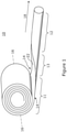
- Figure 1 shows an example of extendible member 10 suitable for use with the various examples and embodiments of the present invention in forming a tube by longitudinally joining the edges of the member.
- the member 10 can be reconfigured between a coiled state 11 and an extended state 12, via a transition stage 13.
- the extended state 12 the member is generally elongated and biased to have a curved or non-linear cross section in a direction transverse to the longitudinal axis 18 of the member.
- This curvature can be adapted and thus the cross section of the extended portion can comprise anything from a closed or substantially closed circular shape, or other generally closed shapes.
- the member 10 is resiliently biased in this curved cross section when extended.
- the member 10 In the coiled state 11 the member 10 is generally opened out at the side edges 14 to have a flat cross section, and is coiled around an axis 16 that is transverse to the longitudinal axis 18 of the member 10.
- the member 10 is thin in cross section to aid coiling, e.g. typically between 0.5 mm and 5 mm for most applications.
- Such members are sometimes referred to as STEMs (slit tubular extendable members).
- the member 10 can be made from various materials suitable for transitioning between a flat, coiled form and an extended, slit tube form, and being resiliently biased in the slit tube form.
- plastics are contemplated as being suitable materials, although others are possible.
- the materials may furthermore be selected in accordance with the joining technique used to joining the edges 14.
- the member 10 comprises a thermoplastic such that the edges 14 of the slit tube can be welded together using thermoplastic welding techniques, as described below.
- the member 10 comprises a composite material having a thermoplastic matrix with fibre reinforcements, such as a fibre reinforced polymer ("FRP" hereafter).
- the fibres may be glass, carbon, or aramid, while the polymer may be polypropylene, polyethylene, a polyamide, polyester thermoplastic, poly-ether-ether-ketone or any other polymer suited to the particular requirements of the task at hand.
- the composite material may comprise a single layer or plural layers with fibres oriented in different directions in each lamina. The use of fibrous materials mechanically enhances the strength and elasticity of the plastic matrix.
- the member 10 is a bistable reelable composite (BRC).
- BRC bistable reelable composite
- Such a bistable member has a first stable state in the coiled form 11, where the cross section of the member 10 is generally flat and a second stable state in the extended form 12, where the cross section of the member is curved as previously described.
- the bistable member 10 may be capable of reversible configuration between its coiled and extended forms a plurality of times. Suitable structures are disclosed in the following international patent applications: WO A 88/08620 , WO-A-97/35706 , WO-A-99/62811 , and WO-A-99/62812 .
- Such bistable structures are available from RolaTube Technology Limited of Lymington, the United Kingdom.
- the BRC in the present example uses the first technique. This involves arranging the fibres to increase the torsional stiffness, and increase the coupling between bending in the longitudinal and transverse directions. This can be achieved by ensuring that in the surface layers of the BRC, i.e. those offset from the midplane of the BRC, stiff fibres are angled relative to the longitudinal axis, e.g. at ⁇ 45°.
- a simple example is the antisymmetric [+45°/-45°/0°/+45°/-45°] fibre lay-up.
- structural members are formed that exhibit a stable geometry in both the extended and coiled states. These manage the problems of difficult handling and complicated mechanisms by forming STEM type structures from materials that have been engineered so as to make them easy to coil and handle.
- the extendible member 10 can have any desired diameter, length, thickness, composition and material properties according to the desired properties of the tube being formed given its intended application.
- the slit tube member 10 may have a susceptor 22 in the region of one or both longitudinal edges 14 of the member 10 as part of the welding process.
- susceptor 22 in the region of one or both longitudinal edges 14 of the member 10 as part of the welding process.
- other welding processes that do not use susceptors are known and may be substituted in the following description.
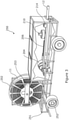
- Figures 2 and 3 show an apparatus 200 for joining longitudinal seams in an extendible coiled member such as that shown in Figure 1 to form a sealed tube, pipe or other sections.
- Figure 2 show the elements of the apparatus 200 separately from any support structure. In practice, these would be fixed to a support structure of some form, whether stationary or mobile such as the vehicle shown in Figure 3 .
- the apparatus 200 comprises a spool 202 on which the coiled part 11 of the member 10 is wound.
- An end 12 of the member 10 extends from the coil and is passed through a pinch wheel drive 204 which progressively drives the member 10 from the spool 202 in an extension direction 18.
- the drive 204 contacts the member in the transition portion 13 as it transitions from the flat form 11 when it is coiled to the curved form 12 when it is extended and in which it is resiliently biased.
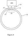
- the member When it has assumed its curved, extended form, the member is passes by a joining device 206. As shown by the cross section of Figure 4 , in its extended form, the side edges 14 of the member overlap and contact each other.
- the joining device 206 provides energy 24 to the member in the region of the overlapping edges 14 to heat the region and create a join seam 20 longitudinally along the member.
- a cooling device 210 such as a fan is provided downstream of the joining device 206 to help cool the molten material in the weld region to speed up the formation of the join.
- the joining device 206 is a welding device or welding head 206 which creates a longitudinal weld along the thermoplastic member.
- Thermoplastic welding is a process for forming a fusion bond between two faying surfaces on two faces of one or more thermoplastic parts. A fusion bond is created when the thermoplastic on the surfaces is heated to the melting or softening point and the two surfaces are brought into contact, so that the molten thermoplastic mixes, and the surfaces are held in contact long enough so that the thermoplastic cools below the softening temperature
- thermoplastics there are many different techniques for welding thermoplastics, some of which have been commercially available for many years for joining composite structures in for example the aerospace, marine and automotive industries. These include manual processes such as hot gas welding and extrusion welding, processes using vibration and frictional heating between the materials such as ultrasonic and linear vibration welding and processes using an electromagnetic heat source such as resistive implant welding, dielectric welding and laser welding. Any of these techniques can be used to join the longitudinal seam in the tube.
- the technique used for welding the thermoplastic is so-called "susceptor welding".
- the member 10 has a strip or layer of susceptor 22 running down one or both edges 14.
- the susceptor 22 lies in the interstices of the weld line where the edges 14 are to be joined.
- the susceptor will heat in the presence of some form of energy, supplied by the welding device 206, that the material to be welded is substantially transparent to.
- heat is got to the weld line between the edges 14 of the slit tube.
- the heat generated melts or softens the thermoplastic in the region of the susceptor for fusion of the facing surfaces of the slit tube edges to be joined.
- susceptors and the energy sources that can heat the susceptors are as follows:
- the apparatus 200 includes a non-destructive testing system 214 downstream of the welding device which tests the integrity of the join.
- a suitable testing system 214 is an ultrasound test system.
- Such devices are known in general in the field of composite manufacture for inspecting parts for flaws based on the propagation of ultrasonic waves in the object or material tested. Briefly, in typical applications, very short ultrasonic pulse-waves with centre frequencies ranging from 0.1-15 MHz, and occasionally up to 50 MHz, are transmitted into materials to detect internal flaws or to characterize materials. In reflection (or pulse-echo) mode, the transducer performs both the sending and the receiving of the pulsed waves as the "sound" is reflected back to the device.
- Reflected ultrasound comes from an interface in its path, such as a wall of the object or from an imperfection within the object. This produces a signal with an amplitude representing the intensity of the reflection and the distance, representing the arrival time of the reflection.
- the testing system 214 can be calibrated by experimentation to detect an unsound weld for the particular type of pipe (its thickness, materials, joining technique, etc.), e.g. by looking for signals of a particular range of amplitudes at a particular range of depths.
- the testing system 214 can be linked to a control system 216 which receives a signal from the testing system 214 indicative of an unsound weld being detected.
- the control system 216 in response can cause the apparatus to reverse the direction of travel of the pipe by controlling the drive 204 so that the portion of pipe containing the faulty weld is again passed under the welding device 206.
- the control system 216 can cause the apparatus to move the affected area more slowly past the welding device 206 to increase the likelihood of making a sound weld at the second pass.
- the procedure can be repeated until it is determined that a sound weld is produced, optionally up to a predetermined number of attempts.
- a second joining device (not shown) can be provided downstream of the testing device 214 which can be activated by the control system 216 in the event of a unsound join being detected to again heat the material in the locality of the fault and re-join the seam. This avoids reversing the direction of travel of the member 10.
- the testing system 214 can alert an operator to the presence of a detected unsound join, enabling the operator to take an appropriate measure in response, such as carrying out further testing to confirm the unsound join and/or taking remedial action to correct the fault.
- the testing system 216 can log the position at which the unsound join is detected to be supplied to the operator, for example using position data generated by a sensor in the spool 202 or drive 204 to track the current position along the coiled member 10.
- Figure 3 shows the apparatus 200 incorporated into a vehicle 250 comprising a platform 251 on wheels 252 on which is mounted supporting structure 253 and/or a housing for supporting and housing the elements of the apparatus shown in Figure 2 and holding them in fixed relative position.
- the apparatus 200 is movable, enabling long sections of pipe to be laid in situ. This lends itself well to being fitted to a trailer or where the seal is needed to be in place immediately. Pipe can be laid over large distances, such as in trenches that can be backfilled as the vehicle advances. This compares favourably with prior art techniques of transporting individual sections of pipe to the installation location and joining them end to end.
- thermoplastic welding is used to join the longitudinal edges of the slit tube member 10.
- other joining techniques can be used employing adhesive bonding to join the tube.
- the joining device supplies heat to the adhesive to progressively form the join, such as heating of a hot-melt adhesive or curing of a thermosetting adhesive.
- thermosetting adhesive In the case of hot melt adhesives the process is the same as for welding except that the adhesive is melted, not the base polymer of the member. In the case of a thermosetting adhesive these are generally "tar-like" in consistency although some are films that first turn liquid as the heat is applied, then go through a curing process.
- the adhesive can be applied as a film to the edge or edges of the member 10. This would make the member easy to handle. However, the adhesive could be applied as a separate film or by coating the bond face as the pipe is extended, or by applying it via the pig (in the examples described below).
- the spool 202 can be driven directly to extend the member 10 rather than using the pinch wheel drive 204.
- the extended end of the member 12 can be tethered as the vehicle 250 moves away, extending the member behind it.
- a guide means (not shown) is positioned downstream of the drive 204 to help guide the edges of the member 10 to assume the abutting or overlapping form in which the seam 20 is to be welded.
- the form of the slit tube member 10 in which it is welded is not identical with the form in which it is resiliently biased.
- the member 10 in its biased form, can form a slit tube with a small separation between the longitudinal edges 14.
- a guide member can the provide an external force to move the edges 14 of the slit tube together into the desired abutting or overlapping position for welding, and/or supply a force to press the edges together during welding to help for the weld.
- a die or rollers are suitable for providing the guide member.
- the biasing force can be removed. This can create a residual hoop stress in the welded tube 10, which can be useful in some cases.
- the resilient bias of the member 10 in its extended form provides most of the curvature needed to form the closed section tube, e.g. the slit tube in its resiliently biased form subtends an angle of at least 270 degrees, or at least 360 degrees, in order to simplify the function of the guide member in positioning the edges of the member in the position in which they are to be welded together.
- the apparatus 200 "extrudes” the pipe - taking a roll of material, preferably Bistable Reeled Composite, transporting it past a welding head with suitable control system and then, for preference, carries out a non-destructive test of the welded pipe as it goes and allows a fault to be reversed and rewelded. It is contemplated that the apparatus can produce welded pipes are rates of between 0.5 m to 10 m per minute.
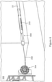
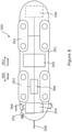
- Figures 5 and 6 show another example of an apparatus 300 for forming pipes from an extendible coiled member 10 such as that shown in Figure 1 according to an embodiment of the present invention.
- the apparatus 300 comprises a spool 302 on which the member 10 is initially coiled 11 and from which an end can be extended.
- the extended end 12 of the member 10 is attached to a "pig" 350 which tows the member 10 into a borehole 400 causing the member 10 to uncoil from the spool 302 in an extension direction 18.
- Pigs are devices known generally in the oil and gas exploration and extraction industries for moving through a pipeline for inspecting and cleaning the pipeline. Often these move with the flow of fluid within a pipeline, although self-powered pigs are known. As used herein, the term “pig” is intended to mean any device constructed and arranged to move within a borehole or pipe or similar.
- the pig 350 comprises a body 351 on which is mounted a controllable gripping device 352 for attaching to the member 10 so as to be able to grip the member 10 while it is towed to the desired position and then release the member 10.
- the pig 350 also includes tractor drives 353, which extend through the sides of the body 351 to contact the borehole 400 or surrounding structure, to propel the pig through the borehole 400.
- the pig 350 has a first joining device 354 at its rear 360 (relative to the direction it travels when towing the member 10) and preferably a join testing device 355, such as an ultrasound detector as described above.
- the pig 350 has a second joining device 356 at the front 362.
- the joining device (or devices) are welding device(s) to provide thermoplastic welds in the thermoplastic member.
- other joining techniques such as adhesive bonding can be used as in the examples of Figures 2 and 3 .
- the pig 350 may have an umbilical 358 attached at its rear 360 which can be used to provide power and or data signals to the pig 350, or carry drill tailings or provide any other service that may be required.
- the umbilical 358 can be wound on a drum 304 positioned at the entrance to the borehole 400 and used to tow the pig back out of the borehole 400.
- umbilical 358 is mounted in front of the spool 302 on which the member 10 is wound and extends through the insides of the member to attach to the pig 350.
- a temporary join forming device 306 is arranged to join the edges 14 of the slit tube together with temporary joins 26 before entering the borehole 400.
- the temporary join forming device is a tag welding head arranged to weld temporary tag welds along the tube, although it will be appreciated that other temporary join forming techniques can be used.
- the diameter of the tube when the temporary welds are formed is at a reduced diameter to the intended diameter of the pipe when installed.
- a guide means 307 can help form the pipe to the preferred diameter to be tag welded.
- Susceptor welding at the seam can be used as in the previous example to weld the pipe, or some other form of welding.
- Tag welds are preferably used, rather than continuous welds, as these are welds are temporary and are intended to be broken, as described below, and so need not be as strong as the final welds.
- the reduced diameter makes towing the tube 10 into the borehole 400 easier due to the reduced friction, and allows longer lengths of pipe to be laid.
- Figure 7A shows the outer diameter of the tube D 1 in its constrained form, which is significantly smaller than the diameter of the bore hole D B .
- Figure 7A also shows in outline the diameter of the pig for comparison D P .
- the tractor 352 can provide propulsion to the pig 350 in either or both directions, or the pig 350 can be towed in either or both directions.
- Other means of propulsion can be used.
- the pig 350 breaks the temporary tag welds 26 as it goes.
- the pig 350 may have a blade 364 or similar member mounted on its body 351 arranged to pass between the edges 14 of the tube and mechanically break the welds 26.
- the tag welds 26 are thermoplastic welds, because thermoplastic welding is a reversible process, the welding device 354 or another welding device in the pig 350 can provide energy 24 to melt the bonds 26 comprising the temporary tags 26.
- the pipe 10 expands to its full diameter D 2 , which preferably is close to the diameter of the borehole D B , as shown in Figure 7B .
- the expansion may be caused by the slit tube member 10 resuming its the resiliently biased form when the constraint of the tags 26 is removed.
- the pig 350 can cause the slit tube to expand as it passes through the inside of the slit tube 10 by way of its external diameter being larger D P than the constrained diameter of the slit tube D 1 .
- the edges 14 of the slit tube member 10 overlap or abut in the position in which they are to be joined together.
- the welding device 354 emits energy 24 causing the susceptor in the region of the edges to rapidly heat, thus melting the thermoplastic in that area and causing the edges 14 to be welded together. When cooled, this creates a welded seam 20 longitudinally along the member 10.
- a cooling device such as a fan, may be provided downstream of the welding device 354 to help cool the molten material in the weld region to speed up the formation of the weld.
- the pig 350 has a non-destructive weld testing device 355, such as an ultrasound detector. If an unsound weld it detected, as in the apparatus 200, the weld can be reformed or the position logged for remedial action later. When reforming the weld, the pig 350 can be reversed so that the welding head 354 again welds the join. Alternatively, to avoid backing up the pig 350, the pig can use a secondary welding head 356 that can be activated to reheat the section of pipe 10 where the unsound weld was detected to remelt the thermoplastic and remake the weld. Again, these processes may be repeated until a sound weld is detected, or it is determined to give up after a predetermined number of attempts.
- a non-destructive weld testing device 355 such as an ultrasound detector.
- the same weld head 354 is used to break the temporary tags 26 and to form the permanent seam 20.
- different weld heads can be employed. It is possibly to use different welding techniques for the temporary tags and the permanent seals.
- different susceptors 22 can be used to form the temporary tags 26, compared to the permanent seals 20 and the pig 350 can have weld heads differently tuned to each susceptor so the pig 350 can control separately how the de-welding of the tags and welding of the seam occurs.
- magnetic energy from a first welding device can be used to break the tags 26, and microwave energy from a second welding device can be used to weld the seam 20 by using different susceptors tuned to those sources of energy.
- tag welds 26 are preferred as being sufficient to temporarily hold the tube in its reduced diameter form whilst it is towed to position in the borehole 400, but a continuous temporary weld could be used.
- the tag welds 26 may consist of a line weld along the outer edge of the overlapping edges 14 away from the permanent weld boundary, as shown in Figure 7A . This leaves the weld face 20 for the permanent weld "clean" to improve the quality of the weld.
- the weld heads 254,256 and ultrasound testing device 355 may be designed to emit energy through 360 degrees of angular position. In this way, all of the tube 10 will be exposed to the energy, thereby assuring that seam area 20 will be exposed. Alternatively one or both may focus the energy specifically on the area of the overlapping edges 14. To achieve this, it may be necessary to provide the pig 350 with some way of rotationally orientating itself relative to the pipe 10 and the edges forming the seam 20. This may be accomplished by gyroscopic means for instance to establish the angular position of the pig 350 relative to the borehole 400 in cases where the pipe 10 has a fixed angular position relative to the borehole 400.
- the pig 350 may have an electronic sensor for detecting some reference in the tube 10.
- an electromagnetic detector can be used to determine the position of the susceptor 22, to provide a reference by which the pig 350 can alter its rotational position and so align the welding head 354 and/or ultrasound detector 355 with the seam 20.
- the pig 350 preferably has a control system 366 which controls the propulsion of the pig via tractors 353 or tow lines 358, the welding devices 354,356, the gripper 352 and the weld testing device 355 and generally controls the functionality of the pig described herein.
- the pig 350 can be controlled remotely via signals sent and received via the umbilical 358.
- the apparatus 300 is useful for deployment in lining blind boreholes or where access is only feasible from one end.
- the pig 350 tows the slit tube member 10 into position in the borehole 400, before welding the longitudinal seam 20 on its return trip.
- the pig 350 can be used in boreholes 400 where access is available from both ends. In this case the pig 350 can alternatively be towed through the borehole from the far end rather than relying on internal propulsion. Alternatively, the reduced diameter tube can be towed in without using a pig, and the pig 350 introduced at either end to perform the welding as it passes through the tube. Different pigs 350 may be used for the towing and the welding operations.
- a faulty weld is detected by the pig 350, an alternative repair procedure can be carried out compared with techniques described above of trying to re-weld the unsound weld. Instead, a repair can be made by welding a thermoplastic liner over the interior walls of the pipe at the site of the faulty weld to seal the tube. The liner is towed to the position of the bad weld and welded in place by the pig 350, using the techniques described above.
- the liner preferably has a susceptor or susceptors that extend around the circumference of the sleeve (in comparison with the member 10 described above where the susceptor is preferably localised at the seam) such that the entire liner is heated by the welding device in the pig and welded to the inside surface of the pipe containing the faulty weld.
- the sleeve can be significantly thinner than the original pipe being repaired as it is largely supported by the original pipe and is subjected to less bursting stress as a result.
- the sleeve can be applied to all of the length of the pipe, or just a section where the faulty weld occurs. This technique can also be used to repair other pipes where it has been determined that a leak, damage or corrosion has occurred.
- FIG. 9 An example of this scenario is shown by Figure 9 in which a borehole is being made by apparatus 900 including a drill head 903 at the end of a drill string 901 suspended by a drilling rig 902 at the surface.
- Casing while drilling may employ the techniques described in relation to Figures 5 to 8 .
- the reel 302 of coiled member 10 to be used as the casing material is positioned generally above the drill string 901 and drill rig 902.
- the extended end 12 of the member 10 is attached to the drill head 903.
- the member 10 is extended from the reel 302 and wraps around the drill string 901 and is (optionally) temporarily welded to a reduced diameter by welding head 904 and advances with the drill head 903.
- the drill string 901 passes and (where applicable to the drilling technology) rotates within the centre of the reduced diameter member 10.
- the smaller diameter of the tag welded pipe makes it easier to pull or push the pipe through a borehole 400.
- the drill string 901 can be withdrawn through the centre of the reduced diameter pipe.
- the drill head 903 may be smaller than the reduced diameter tube such that it can be withdrawn through the centre of the tube (it being understood that drill heads are typically configured to bore a hole larger than their diameter such that the drill head can bore a hole large enough for the reduced diameter tube to be advanced whilst still being capable of being withdrawn through the centre of the tube).
- the pig 350 can then be lowered into the pipe in the borehole and towed back to the surface, expanding the pipe by breaking the temporary welds and welding the permanent longitudinal seam as it is withdrawn (following the principles described above in relation to Figures 5 to 7 ) Thus, the casing is made to expand to fit tight within the borehole 400.
- the pig can be incorporated into the drill string 901 itself, e.g. adjacent the drill head.
- the temporary welds are broken and the permanent welds formed as the drill head is withdrawn.
- the pig does not need its own source of locomotion, as it is moved with and as part of the drill string.
- casing whilst drilling may employ the techniques shown by Figures 2 to 4 .
- the welding head 904 forms the permanent longitudinal seam in the pipe 10 at the top of the borehole 400 as the member 10 comes off the reel 302 and wraps around the drill string.
- the pipe is welded at its full diameter in which it is installed in the wellbore, rather than being temporary welded at a reduced diameter whilst it is towed into the borehole 400.
- the weight of the drill string in this case can be used to provide sufficient force to move the casing into the borehole 400 as drilling progresses.
- the drill string is typically removed from the borehole, whilst a new section of case is fitted to the top of the casing and used to hammer down the existing casing in the borehole. This becomes progressively difficult unless the casing is much smaller than the borehole. This has a significant effect on the volume of product that can flow. This also means that the casing must be grouted in place once the borehole is complete. Repeat trips with the drill string also add hugely to the cost of drilling, not to mention the huge cost and energy needed to ship meal pipes to the drilling head end.
- the preferred embodiments of the apparatus 900 described above have the ability to reduce some or all of these problems by casing the borehole 400 in a single run.
- the techniques can be used with any suitable drilling technology, i.e. hydraulic or electric powered drill bits, or drilling by rotating the drill string.
- the main joining techniques described in the examples is thermoplastic welding and particularly susceptor welding where the joining devices emit energy to cause the material to heat and the weld to form.
- the principles disclosed herein extend to other joining techniques, such as using adhesive bonding, where the energy emitted by the joining devices heats the adhesive such that the adhesive bond can form.
- All of the techniques disclosed herein can apply to new pipes - free standing or within boreholes and to pipe lining where the thin cross section of a BRC relative to its strength and barrier capability can provide a liner with much less occlusion of the bore of the pipe to be re-lined.
- the apparatus described can be used to lay pipes of long lengths, e.g. 100s of meters or kilometres.
- a spool of coiled member can contain enough BRC for a pipe 5 km long.
Landscapes
- Engineering & Computer Science (AREA)
- Mechanical Engineering (AREA)
- Physics & Mathematics (AREA)
- Mining & Mineral Resources (AREA)
- Life Sciences & Earth Sciences (AREA)
- Geology (AREA)
- Optics & Photonics (AREA)
- General Engineering & Computer Science (AREA)
- Electromagnetism (AREA)
- Health & Medical Sciences (AREA)
- Toxicology (AREA)
- Fluid Mechanics (AREA)
- Geochemistry & Mineralogy (AREA)
- General Life Sciences & Earth Sciences (AREA)
- Environmental & Geological Engineering (AREA)
- Plasma & Fusion (AREA)
- Chemical & Material Sciences (AREA)
- Combustion & Propulsion (AREA)
- Thermal Sciences (AREA)
- Quality & Reliability (AREA)
- Oral & Maxillofacial Surgery (AREA)
- Lining Or Joining Of Plastics Or The Like (AREA)
- Pipe Accessories (AREA)
Description
- The present invention relates to an apparatus and method of joining a longitudinal seam in a tube in a borehole or in a pipe.
- There are many situations where it is desired to deploy closed pipes, tubes, and the like. Examples include laying pipes transporting water or other fluids and lining existing pipes and boreholes, for instance in the oil industry. Currently, installation typically involves shipping many short lengths of fully formed pipe to the installation site and joining them together end to end. This is has a large overhead of time and effort and energy cost in shipping the bulky pipes to their final destination, particularly where the overall length of the pipe is to extend hundreds of meters or even kilometres. Also in the case of drilling boreholes in many cases the drill have to be withdrawn to allow the bore to have a pipe inserted, followed by the re-insertion of the drill and so on in a repetitive manner. The provision of a pipe that could be continuously deployed behind the drill would have clear economic benefits. This can be the case in a range of industries, from bores for oil and gas to conduits for electrical or communications cables and many other applications.
-
US20070267785A1 describes a method of lining a pipe in which a composite lining, comprising a structural layer for providing structural integrity and a containment layer for providing fluid impermeability. The structural layer is a flat strip of material which is first spirally formed within a pipe to line it, followed by a second operation in which a containment layer is introduced to the pipe and welded to the lining to make it fluid impermeable. - Winchester D "radical technology in the pipeline", OFFSHORE ENGINEER,,1 June 1991, ISSN: 0305-876X describes methods of laying flow lines in which a reeled composite member is extended from a reel to form a tubular form, and the edges welded together.
- What is needed are improved ways of deploying pipes, tubes and the like.
- The present invention is as defined by the independent claims.
- According to a first aspect of the present invention, there is provided an apparatus for joining a longitudinal seam in a tube in a borehole, wherein the tube is a pipe or a pipe liner or a casing, the apparatus comprising:
- a spool for holding a coiled member such that an end of the member in an extended form can be fed into a borehole or pipe, wherein the member transitions from a flat form in transverse cross section when coiled to a slit tube form when extended, in which form the member is resiliently biased, the member comprising a composite having a thermoplastic matrix with fibre reinforcement layers configured such that the member is stable in the coiled form and in the extended form;
- a device for pushing or pulling the extended member into the borehole until the member has reached a desired position;
- a pig arranged to move through the borehole or pipe down the inside of the extended member,
- wherein the pig has joining means arranged to provide energy to a portion of the member to cause heating so as to progressively join together the edges of the slit tube as the pig passes along the inside of the tube to form a longitudinal seam in the tube.
- In an embodiment, the pig is used to tow the extended member into the borehole and is reversible in direction when moving through the borehole down the inside of the extended member.
- In an embodiment, the pig comprises means of propulsion for moving through the borehole in one or both directions. The propulsion means may be a traction drive or crawler, which extends through the sides of the pig to contact the surrounding material and develop traction by which the drive can propel the pig through the hole. Alternatively, the pig can be through the borehole.
- In an embodiment, the means of propulsion of the pig are reversible.
- In an embodiment the apparatus comprises an umbilical cable attached to the pig and drive means for the umbilical cable to propel the pig through the borehole by way of retracting the umbilical cable. The umbilical can carry power and data signals to the pig in addition to towing the pig. The data signals can be used to control the pig, e.g. to manoeuvre the pig to the desired position in the borehole and to communicate the results of join testing to a control device at the head of the borehole.
- In an embodiment, the member comprises a susceptor in the region of the seam and welding device in the pig is arranged to provide electromagnetic energy to the susceptor to cause welding of the edges of the member.
- In an embodiment, the apparatus comprises a joining device positioned between the spool and the borehole arranged to temporarily join the slit tube member at a reduced diameter compared with the diameter of the slit tube in its resiliently biased form so as to make it easier to push or pull the reduced diameter tube into the borehole or pipe, wherein the pig is arranged to break the temporary joins as it passes along the inside of the tube. Thus, the slit tube member can be towed into the borehole at a reduced diameter, which reduces the friction acting on the member and makes it practical to tow long lengths into the borehole. The pig then breaks the tags, allowing the member to expand to a larger diameter when in the borehole at which diameter it is joined by the pig. Thus, the increased final size of the tube allows a greater throughflow rate in the pipe. The pipe can also be made to expand to the size of the borehole, such that there is no necessity to insert grout between the pipe and the borehole.
- The pig can break the temporary joins by mechanical means, or by using heat to melt the joins. Susceptor welding can be used to form the temporary welds. As welding is reversible, the same susceptor can be used for the temporary and the permanent welds. Thus, to form the temporary weld, the slit tube can be constrained, e.g. by passing it through a die or rollers or other guide structure, to assume a reduced diameter, and the susceptor heated at intervals to form tag welds holding the slit tube at this diameter. When the pig travels through the extended member, the welding device heats the susceptor material, causing the tag welds to melt and the slit tube to expand to its final form. As the susceptor continues to be heated, this creates a new weld line between the edges of the slit tube in this expanded form which forms the final welded seam as the seam cools down.
- In an embodiment, the temporary join line is along the outer edge of the overlap, keeping the join boundary clean. Thus, the temporary joins do not interfere with the final joined seam and risk weakening the final join.
- In an embodiment, the pig has a greater diameter than the diameter of the slit tube in its resiliently biased form such that it expands the slit tube as it passed along the inside of the extended member prior to joining it at the expanded diameter. This technique does not rely on the resilient bias of the slit tube in achieving the expanded form once the temporary joins are broken by the pig, but instead uses the external size of the pig to force the slit tube further open.
- In an embodiment, the pig comprises a detector downstream of the joining device for testing the join integrity. As discussed above, an ultrasound detector can be used to find an unsound join and take remedial action, such as reforming the join. In this respect, the pig can be backed up, so the joining device can reheat the seam to cause it to bond. Alternatively, the pig can have a secondary joining device after the detector which can be activated when a faulty join is discovered to locally reheat the seam to cause it to bond.
- In an embodiment, a drill string is used to tow the extended member into the borehole and/or the pig is incorporated into a drill string.
- According to a second aspect of the present invention, there is provided a method of joining a longitudinal seam in a tube in a borehole wherein the tube is a pipe or pipe liner or a casing, the method comprising:
- progressively unspooling a coiled member into an extended form in which form the member is resiliently biased and pushing or pulling the extended member into the borehole until the member has reached a desired position, wherein the member transitions from a flat form in transverse cross section when coiled to a slit tube form when extended, the member comprising a composite having a thermoplastic matrix with fibre reinforcement layers configured such that the member is stable in the coiled form and in the extended form;
- propelling a pig through the borehole down the inside of the extended member; and,
- progressively joining together the edges of the slit tube with a joining device in the pig by providing energy to heat the member as the pig passes along the inside of the tube to form a longitudinal seam in the tube.
- The method may comprise towing the extended member into the borehole with the pig and before reversing the direction of the pig when propelling the pig through the borehole down the inside of the extended member.
- The method may comprise using susceptor welding to weld the longitudinal seam in the member.
- The method may comprise, towing the member into the borehole at a reduced diameter compared with the diameter of the borehole; and,
expanding the diameter of the member with the pig as it progressively moves through the member before joining the longitudinal seam at the expanded diameter. - The method may comprise testing the join integrity with the pig and reforming the join.
- In embodiments, the methods described above comprise forming the member into a tube around a drill string and advancing the tube into a borehole as drilling progresses.
- Thus the preferred aspects and embodiments allow long lengths of closed section tube to be deployed from a coiled member. The tube is preferably at least 10m, or at least 100m, or at least 1000m, or more long.
- Thus, the pig can be used to repair a tube, whether a seamed tube or otherwise, by joining a lining to the inside of the tube using joining. The lining can be thinner than the tube being repaired to avoid reducing the bore excessively and can cover the entire length of the tube or just a damaged portion. Using the principles described herein, the liner can be tag joined at a reduced diameter when being towed into position, and then expanded by the pig by breaking the tag joins and using the diameter of the pig or the resilient bias of the liner in its extended form to come up to the desired diameter, which preferably fits closely to the interior bore of the damaged pipe. Welding or adhesive may be used to join the liner to the tube to be repaired. Preferably susceptor heating is used to join the liner in place, using a susceptor that extends throughout the width of the member so as to weld the liner to the pipe through a full 360 degrees, either by welding or by an adhesive applied to the outer surface of the split tube. A test system in the pig, such as ultrasound detector, can detect whether or not the liner has been successfully joined in place.
- It will be appreciated that any features expressed herein as being provided "in one example" or "in an embodiment" or as being "preferable" may be provided in combination with any one or more other such features together with any one or more of the aspects of the present invention. In particular, the extendible member, joining techniques and join testing system described in relation to one aspect may generally be applicable to the others.
- Embodiments of the present invention will now be described by way of example with reference to the accompanying drawings, in which:
-
Figure 1 shows an example of an extendible member suitable for use with embodiments of the present invention; -
Figures 2 and3 show a comparative example of apparatus for deploying a pipe according to an embodiment of the present invention; -
Figure 4 shows in cross section an example of a seam being formed by the apparatus ofFigures 2 and3 ; -
Figures 5 and6 show an example of apparatus for deploying a pipe according to another embodiment of the present invention; -
Figure 7 shows in cross section an example of a seam being formed by the apparatus ofFigures 5 and6 ; -
Figure 8 shows schematically part of the apparatus ofFigures 5 and6 ; and, -
Figure 9 shows an example of casing a borehole while drilling according to an embodiment of the present invention. -
Figure 1 shows an example ofextendible member 10 suitable for use with the various examples and embodiments of the present invention in forming a tube by longitudinally joining the edges of the member. Themember 10 can be reconfigured between acoiled state 11 and anextended state 12, via atransition stage 13. In theextended state 12 the member is generally elongated and biased to have a curved or non-linear cross section in a direction transverse to thelongitudinal axis 18 of the member. (References to longitudinal axis or longitudinal extent or direction of extension in this document generally refer to this axis 18). This curvature can be adapted and thus the cross section of the extended portion can comprise anything from a closed or substantially closed circular shape, or other generally closed shapes. Themember 10 is resiliently biased in this curved cross section when extended. This gives structural rigidity to themember 10 when extended. In the coiledstate 11 themember 10 is generally opened out at the side edges 14 to have a flat cross section, and is coiled around anaxis 16 that is transverse to thelongitudinal axis 18 of themember 10. Themember 10 is thin in cross section to aid coiling, e.g. typically between 0.5 mm and 5 mm for most applications. Such members are sometimes referred to as STEMs (slit tubular extendable members). - The
member 10 can be made from various materials suitable for transitioning between a flat, coiled form and an extended, slit tube form, and being resiliently biased in the slit tube form. In general, plastics are contemplated as being suitable materials, although others are possible. The materials may furthermore be selected in accordance with the joining technique used to joining theedges 14. - In the present example, the
member 10 comprises a thermoplastic such that theedges 14 of the slit tube can be welded together using thermoplastic welding techniques, as described below. In the present example, themember 10 comprises a composite material having a thermoplastic matrix with fibre reinforcements, such as a fibre reinforced polymer ("FRP" hereafter). The fibres may be glass, carbon, or aramid, while the polymer may be polypropylene, polyethylene, a polyamide, polyester thermoplastic, poly-ether-ether-ketone or any other polymer suited to the particular requirements of the task at hand. The composite material may comprise a single layer or plural layers with fibres oriented in different directions in each lamina. The use of fibrous materials mechanically enhances the strength and elasticity of the plastic matrix. The extent that strength and elasticity are enhanced in a fibre reinforced plastic depends on the mechanical properties of both the fibre and the matrix, their volume relative to one another, and the fibre length and orientation within the matrix. FRPs are widely used in many areas such as aerospace and automotive industries, and are not described in detail herein. - In the present example, the
member 10 is a bistable reelable composite (BRC). Such a bistable member has a first stable state in the coiledform 11, where the cross section of themember 10 is generally flat and a second stable state in the extendedform 12, where the cross section of the member is curved as previously described. Thebistable member 10 may be capable of reversible configuration between its coiled and extended forms a plurality of times. Suitable structures are disclosed in the following international patent applications:WO A 88/08620 WO-A-97/35706 WO-A-99/62811 WO-A-99/62812 - In general, there are two ways to make a tube bistable; either by altering the bending stiffnesses of the structure so that it is no longer isotropic, for instance by using a fibre-reinforced composite, or by setting up an initial prestress in the structure. The BRC in the present example uses the first technique. This involves arranging the fibres to increase the torsional stiffness, and increase the coupling between bending in the longitudinal and transverse directions. This can be achieved by ensuring that in the surface layers of the BRC, i.e. those offset from the midplane of the BRC, stiff fibres are angled relative to the longitudinal axis, e.g. at ±45°. A simple example is the antisymmetric [+45°/-45°/0°/+45°/-45°] fibre lay-up.
- In engineering terms these surface layers have high Poisson's ratios. It is well known that as a curved shell is straightened the inner surface gets longer and the outer surface gets shorter. Thus, when a section of the extended tube is opened, as the initial curvature straightens, the surface fibres are deformed which, due to their high Poisson's ratio, exert a force acting to curve the opened section longitudinally into its coiled form. The tube coils with same sense curvature, i.e. the centre of curvature is on the same side of the structure in both forms.
- Normally when something is bent the amount of energy stored by that bending (the total strain energy) rises as the degree of bending increases. In BRCs, once the initial curvature is straightened as the tube is opened, the stiffness along the longitudinal axis drops and the forces acting on the material of the tube arising by the deformed surface fibres can act to flip it into the coiled form. As this second curves forms, the total strain energy drops, thereby forming a second stable form for this section.
- These principle operate in reverse when moving from the coiled state to the extended state.
- Thus, structural members are formed that exhibit a stable geometry in both the extended and coiled states. These manage the problems of difficult handling and complicated mechanisms by forming STEM type structures from materials that have been engineered so as to make them easy to coil and handle.
- There now follows a description of various techniques for forming tubes from these extendible members. To this end, the
extendible member 10 can have any desired diameter, length, thickness, composition and material properties according to the desired properties of the tube being formed given its intended application. - As will be described below, the
slit tube member 10 may have a susceptor 22 in the region of one or bothlongitudinal edges 14 of themember 10 as part of the welding process. However, it will be appreciated that other welding processes that do not use susceptors are known and may be substituted in the following description. -
Figures 2 and3 show anapparatus 200 for joining longitudinal seams in an extendible coiled member such as that shown inFigure 1 to form a sealed tube, pipe or other sections.Figure 2 show the elements of theapparatus 200 separately from any support structure. In practice, these would be fixed to a support structure of some form, whether stationary or mobile such as the vehicle shown inFigure 3 . - The
apparatus 200 comprises aspool 202 on which thecoiled part 11 of themember 10 is wound. Anend 12 of themember 10 extends from the coil and is passed through apinch wheel drive 204 which progressively drives themember 10 from thespool 202 in anextension direction 18. Thedrive 204 contacts the member in thetransition portion 13 as it transitions from theflat form 11 when it is coiled to thecurved form 12 when it is extended and in which it is resiliently biased. - When it has assumed its curved, extended form, the member is passes by a joining
device 206. As shown by the cross section ofFigure 4 , in its extended form, the side edges 14 of the member overlap and contact each other. The joiningdevice 206 providesenergy 24 to the member in the region of the overlappingedges 14 to heat the region and create ajoin seam 20 longitudinally along the member. Acooling device 210, such as a fan is provided downstream of the joiningdevice 206 to help cool the molten material in the weld region to speed up the formation of the join. - In the present example, the joining
device 206 is a welding device orwelding head 206 which creates a longitudinal weld along the thermoplastic member. Thermoplastic welding is a process for forming a fusion bond between two faying surfaces on two faces of one or more thermoplastic parts. A fusion bond is created when the thermoplastic on the surfaces is heated to the melting or softening point and the two surfaces are brought into contact, so that the molten thermoplastic mixes, and the surfaces are held in contact long enough so that the thermoplastic cools below the softening temperature - There are many different techniques for welding thermoplastics, some of which have been commercially available for many years for joining composite structures in for example the aerospace, marine and automotive industries. These include manual processes such as hot gas welding and extrusion welding, processes using vibration and frictional heating between the materials such as ultrasonic and linear vibration welding and processes using an electromagnetic heat source such as resistive implant welding, dielectric welding and laser welding. Any of these techniques can be used to join the longitudinal seam in the tube.
- In the present example, the technique used for welding the thermoplastic is so-called "susceptor welding". The
member 10 has a strip or layer ofsusceptor 22 running down one or bothedges 14. Thus, in extended slit tube form of the member, with theedges 14 abutting or overlapping in the position they are to be welded together, thesusceptor 22 lies in the interstices of the weld line where theedges 14 are to be joined. The susceptor" will heat in the presence of some form of energy, supplied by thewelding device 206, that the material to be welded is substantially transparent to. Thus, heat is got to the weld line between theedges 14 of the slit tube. The heat generated melts or softens the thermoplastic in the region of the susceptor for fusion of the facing surfaces of the slit tube edges to be joined. - Some examples of susceptors and the energy sources that can heat the susceptors are as follows:
- Some ferrite and ferro-magnetic materials can be heated by an oscillating magnetic field
- Some ferrite, metallic - such as iron filings - and other materials will heat in a microwave field
- A source of infra-red radiation can be tuned such as to minimise absorption by the material of the pipe to be welded whilst putting a material that is highly absorbent of the same frequencies into the weld boundary, such as carbon black
- Lasers can be used as an alternative to tuned infra-red sources, with an absorbent die-stuff in the weld boundary. This technique is generally referred to as "laser clear die".
- In general terms, many materials heat up in an RF field, whilst the polymers and reinforcing fibres used for this type of fibre reinforced coilable pipe do not.
- The advantage of these techniques as a body is that the weld face can be held closed throughout the welding operation.
- Optionally, the
apparatus 200 includes anon-destructive testing system 214 downstream of the welding device which tests the integrity of the join. An example of asuitable testing system 214 is an ultrasound test system. Such devices are known in general in the field of composite manufacture for inspecting parts for flaws based on the propagation of ultrasonic waves in the object or material tested. Briefly, in typical applications, very short ultrasonic pulse-waves with centre frequencies ranging from 0.1-15 MHz, and occasionally up to 50 MHz, are transmitted into materials to detect internal flaws or to characterize materials. In reflection (or pulse-echo) mode, the transducer performs both the sending and the receiving of the pulsed waves as the "sound" is reflected back to the device. Reflected ultrasound comes from an interface in its path, such as a wall of the object or from an imperfection within the object. This produces a signal with an amplitude representing the intensity of the reflection and the distance, representing the arrival time of the reflection. Thetesting system 214 can be calibrated by experimentation to detect an unsound weld for the particular type of pipe (its thickness, materials, joining technique, etc.), e.g. by looking for signals of a particular range of amplitudes at a particular range of depths. - The
testing system 214 can be linked to acontrol system 216 which receives a signal from thetesting system 214 indicative of an unsound weld being detected. Thecontrol system 216 in response can cause the apparatus to reverse the direction of travel of the pipe by controlling thedrive 204 so that the portion of pipe containing the faulty weld is again passed under thewelding device 206. Thecontrol system 216 can cause the apparatus to move the affected area more slowly past thewelding device 206 to increase the likelihood of making a sound weld at the second pass. The procedure can be repeated until it is determined that a sound weld is produced, optionally up to a predetermined number of attempts. - Alternatively, a second joining device (not shown) can be provided downstream of the
testing device 214 which can be activated by thecontrol system 216 in the event of a unsound join being detected to again heat the material in the locality of the fault and re-join the seam. This avoids reversing the direction of travel of themember 10. - Alternatively or additionally, the
testing system 214 can alert an operator to the presence of a detected unsound join, enabling the operator to take an appropriate measure in response, such as carrying out further testing to confirm the unsound join and/or taking remedial action to correct the fault. Thetesting system 216 can log the position at which the unsound join is detected to be supplied to the operator, for example using position data generated by a sensor in thespool 202 or drive 204 to track the current position along the coiledmember 10. -
Figure 3 shows theapparatus 200 incorporated into avehicle 250 comprising aplatform 251 onwheels 252 on which is mounted supportingstructure 253 and/or a housing for supporting and housing the elements of the apparatus shown inFigure 2 and holding them in fixed relative position. - Thus, the
apparatus 200 is movable, enabling long sections of pipe to be laid in situ. This lends itself well to being fitted to a trailer or where the seal is needed to be in place immediately. Pipe can be laid over large distances, such as in trenches that can be backfilled as the vehicle advances. This compares favourably with prior art techniques of transporting individual sections of pipe to the installation location and joining them end to end. - In the example of
Figures 2 and3 , thermoplastic welding is used to join the longitudinal edges of theslit tube member 10. However, other joining techniques can be used employing adhesive bonding to join the tube. In these examples, the joining device supplies heat to the adhesive to progressively form the join, such as heating of a hot-melt adhesive or curing of a thermosetting adhesive. - In the case of hot melt adhesives the process is the same as for welding except that the adhesive is melted, not the base polymer of the member. In the case of a thermosetting adhesive these are generally "tar-like" in consistency although some are films that first turn liquid as the heat is applied, then go through a curing process.
- The adhesive can be applied as a film to the edge or edges of the
member 10. This would make the member easy to handle. However, the adhesive could be applied as a separate film or by coating the bond face as the pipe is extended, or by applying it via the pig (in the examples described below). - Optionally, the
spool 202 can be driven directly to extend themember 10 rather than using thepinch wheel drive 204. Alternatively, the extended end of themember 12 can be tethered as thevehicle 250 moves away, extending the member behind it. - Optionally a guide means (not shown) is positioned downstream of the
drive 204 to help guide the edges of themember 10 to assume the abutting or overlapping form in which theseam 20 is to be welded. In embodiments, the form of theslit tube member 10 in which it is welded is not identical with the form in which it is resiliently biased. For instance, in its biased form, themember 10 can form a slit tube with a small separation between the longitudinal edges 14. A guide member can the provide an external force to move theedges 14 of the slit tube together into the desired abutting or overlapping position for welding, and/or supply a force to press the edges together during welding to help for the weld. A die or rollers are suitable for providing the guide member. Once, thetube 10 is welded, the biasing force can be removed. This can create a residual hoop stress in the weldedtube 10, which can be useful in some cases. However, in these embodiments, it is preferred that the resilient bias of themember 10 in its extended form provides most of the curvature needed to form the closed section tube, e.g. the slit tube in its resiliently biased form subtends an angle of at least 270 degrees, or at least 360 degrees, in order to simplify the function of the guide member in positioning the edges of the member in the position in which they are to be welded together. - Thus, the
apparatus 200 "extrudes" the pipe - taking a roll of material, preferably Bistable Reeled Composite, transporting it past a welding head with suitable control system and then, for preference, carries out a non-destructive test of the welded pipe as it goes and allows a fault to be reversed and rewelded. It is contemplated that the apparatus can produce welded pipes are rates of between 0.5 m to 10 m per minute. -
Figures 5 and6 show another example of anapparatus 300 for forming pipes from an extendible coiledmember 10 such as that shown inFigure 1 according to an embodiment of the present invention. - The
apparatus 300 comprises aspool 302 on which themember 10 is initially coiled 11 and from which an end can be extended. Theextended end 12 of themember 10 is attached to a "pig" 350 which tows themember 10 into a borehole 400 causing themember 10 to uncoil from thespool 302 in anextension direction 18. - "Pigs" are devices known generally in the oil and gas exploration and extraction industries for moving through a pipeline for inspecting and cleaning the pipeline. Often these move with the flow of fluid within a pipeline, although self-powered pigs are known. As used herein, the term "pig" is intended to mean any device constructed and arranged to move within a borehole or pipe or similar.
- As shown by
Figure 8 , thepig 350 comprises abody 351 on which is mounted a controllablegripping device 352 for attaching to themember 10 so as to be able to grip themember 10 while it is towed to the desired position and then release themember 10. Thepig 350 also includes tractor drives 353, which extend through the sides of thebody 351 to contact the borehole 400 or surrounding structure, to propel the pig through theborehole 400. Thepig 350 has a first joiningdevice 354 at its rear 360 (relative to the direction it travels when towing the member 10) and preferably ajoin testing device 355, such as an ultrasound detector as described above. Optionally thepig 350 has a second joiningdevice 356 at the front 362. In this example, the joining device (or devices) are welding device(s) to provide thermoplastic welds in the thermoplastic member. However, as will be appreciated, other joining techniques such as adhesive bonding can be used as in the examples ofFigures 2 and3 . - The
pig 350 may have an umbilical 358 attached at its rear 360 which can be used to provide power and or data signals to thepig 350, or carry drill tailings or provide any other service that may be required. The umbilical 358 can be wound on adrum 304 positioned at the entrance to theborehole 400 and used to tow the pig back out of theborehole 400. Thus umbilical 358 is mounted in front of thespool 302 on which themember 10 is wound and extends through the insides of the member to attach to thepig 350. - As the
member 10 is extended from thespool 302, it transitions from theflat form 11 when it is coiled to theslit tube form 12 when it is extended and in which it is resiliently biased. Preferably a temporaryjoin forming device 306 is arranged to join theedges 14 of the slit tube together with temporary joins 26 before entering theborehole 400. In this example, the temporary join forming device is a tag welding head arranged to weld temporary tag welds along the tube, although it will be appreciated that other temporary join forming techniques can be used. Preferably the diameter of the tube when the temporary welds are formed is at a reduced diameter to the intended diameter of the pipe when installed. A guide means 307, such as a die or rollers, can help form the pipe to the preferred diameter to be tag welded. Susceptor welding at the seam can be used as in the previous example to weld the pipe, or some other form of welding. Tag welds are preferably used, rather than continuous welds, as these are welds are temporary and are intended to be broken, as described below, and so need not be as strong as the final welds. The reduced diameter makes towing thetube 10 into the borehole 400 easier due to the reduced friction, and allows longer lengths of pipe to be laid.Figure 7A shows the outer diameter of the tube D1 in its constrained form, which is significantly smaller than the diameter of the bore hole DB.Figure 7A also shows in outline the diameter of the pig for comparison DP. - When the
pipe 10 has been towed to the desired installation position in theborehole 400 by thepig 350, thepig 350 is reversed back out of the borehole 400 the way it came, as shown byFigure 6 , by rewinding the umbilical 358 on thedrum 304. - Alternatively, the
tractor 352 can provide propulsion to thepig 350 in either or both directions, or thepig 350 can be towed in either or both directions. Other means of propulsion can be used. - As the
pig 350 is reversed back out of theborehole 400, it now travels down the inside of themember 10. As it progresses, thepig 350 breaks the temporary tag welds 26 as it goes. Thepig 350 may have ablade 364 or similar member mounted on itsbody 351 arranged to pass between theedges 14 of the tube and mechanically break thewelds 26. Alternatively or additionally, where the tag welds 26 are thermoplastic welds, because thermoplastic welding is a reversible process, thewelding device 354 or another welding device in thepig 350 can provideenergy 24 to melt thebonds 26 comprising the temporary tags 26. - As the
tags 26 are progressively broken, thepipe 10 expands to its full diameter D2, which preferably is close to the diameter of the borehole DB, as shown inFigure 7B . The expansion may be caused by theslit tube member 10 resuming its the resiliently biased form when the constraint of thetags 26 is removed. Alternatively or additionally, thepig 350 can cause the slit tube to expand as it passes through the inside of theslit tube 10 by way of its external diameter being larger DP than the constrained diameter of the slit tube D1. - Once in its expanded form, the
edges 14 of theslit tube member 10 overlap or abut in the position in which they are to be joined together. As thepig 350 progresses along the slit tube, thewelding device 354 emitsenergy 24 causing the susceptor in the region of the edges to rapidly heat, thus melting the thermoplastic in that area and causing theedges 14 to be welded together. When cooled, this creates a weldedseam 20 longitudinally along themember 10. A cooling device, such as a fan, may be provided downstream of thewelding device 354 to help cool the molten material in the weld region to speed up the formation of the weld. - The
pig 350 has a non-destructiveweld testing device 355, such as an ultrasound detector. If an unsound weld it detected, as in theapparatus 200, the weld can be reformed or the position logged for remedial action later. When reforming the weld, thepig 350 can be reversed so that thewelding head 354 again welds the join. Alternatively, to avoid backing up thepig 350, the pig can use asecondary welding head 356 that can be activated to reheat the section ofpipe 10 where the unsound weld was detected to remelt the thermoplastic and remake the weld. Again, these processes may be repeated until a sound weld is detected, or it is determined to give up after a predetermined number of attempts. - In some embodiments, the
same weld head 354 is used to break thetemporary tags 26 and to form thepermanent seam 20. Alternatively, different weld heads can be employed. It is possibly to use different welding techniques for the temporary tags and the permanent seals. For instance,different susceptors 22 can be used to form thetemporary tags 26, compared to thepermanent seals 20 and thepig 350 can have weld heads differently tuned to each susceptor so thepig 350 can control separately how the de-welding of the tags and welding of the seam occurs. For instance, magnetic energy from a first welding device can be used to break thetags 26, and microwave energy from a second welding device can be used to weld theseam 20 by using different susceptors tuned to those sources of energy. - It will be appreciated, that tag welds 26 are preferred as being sufficient to temporarily hold the tube in its reduced diameter form whilst it is towed to position in the
borehole 400, but a continuous temporary weld could be used. - The tag welds 26 may consist of a line weld along the outer edge of the overlapping
edges 14 away from the permanent weld boundary, as shown inFigure 7A . This leaves the weld face 20 for the permanent weld "clean" to improve the quality of the weld. - The weld heads 254,256 and
ultrasound testing device 355 may be designed to emit energy through 360 degrees of angular position. In this way, all of thetube 10 will be exposed to the energy, thereby assuring thatseam area 20 will be exposed. Alternatively one or both may focus the energy specifically on the area of the overlapping edges 14. To achieve this, it may be necessary to provide thepig 350 with some way of rotationally orientating itself relative to thepipe 10 and the edges forming theseam 20. This may be accomplished by gyroscopic means for instance to establish the angular position of thepig 350 relative to the borehole 400 in cases where thepipe 10 has a fixed angular position relative to theborehole 400. Alternatively, mechanical means may be used to keep thepig 350 at a constant angular position relative to theseam 20 and so align thewelding head 354 and/orultrasound detector 355 with theseam 20, e.g. the interaction of theblade 360 or another member with theseam 20 can be used to maintain a constant the rotational position of thepig 350 with respect to theseam 20. Alternatively thepig 350 may have an electronic sensor for detecting some reference in thetube 10. For example, where thesusceptor 22 is a foil layer or other metallic susceptor, an electromagnetic detector can be used to determine the position of thesusceptor 22, to provide a reference by which thepig 350 can alter its rotational position and so align thewelding head 354 and/orultrasound detector 355 with theseam 20. - The
pig 350 preferably has acontrol system 366 which controls the propulsion of the pig viatractors 353 ortow lines 358, the welding devices 354,356, thegripper 352 and theweld testing device 355 and generally controls the functionality of the pig described herein. Alternatively thepig 350 can be controlled remotely via signals sent and received via the umbilical 358. - The
apparatus 300 is useful for deployment in lining blind boreholes or where access is only feasible from one end. In this case, thepig 350 tows theslit tube member 10 into position in theborehole 400, before welding thelongitudinal seam 20 on its return trip. - However the
pig 350 can be used inboreholes 400 where access is available from both ends. In this case thepig 350 can alternatively be towed through the borehole from the far end rather than relying on internal propulsion. Alternatively, the reduced diameter tube can be towed in without using a pig, and thepig 350 introduced at either end to perform the welding as it passes through the tube.Different pigs 350 may be used for the towing and the welding operations. - If a faulty weld is detected by the
pig 350, an alternative repair procedure can be carried out compared with techniques described above of trying to re-weld the unsound weld. Instead, a repair can be made by welding a thermoplastic liner over the interior walls of the pipe at the site of the faulty weld to seal the tube. The liner is towed to the position of the bad weld and welded in place by thepig 350, using the techniques described above. The liner preferably has a susceptor or susceptors that extend around the circumference of the sleeve (in comparison with themember 10 described above where the susceptor is preferably localised at the seam) such that the entire liner is heated by the welding device in the pig and welded to the inside surface of the pipe containing the faulty weld. The sleeve can be significantly thinner than the original pipe being repaired as it is largely supported by the original pipe and is subjected to less bursting stress as a result. The sleeve can be applied to all of the length of the pipe, or just a section where the faulty weld occurs. This technique can also be used to repair other pipes where it has been determined that a leak, damage or corrosion has occurred. - The techniques disclosed herein lend themselves well to "casing whilst drilling". An example of this scenario is shown by
Figure 9 in which a borehole is being made byapparatus 900 including adrill head 903 at the end of adrill string 901 suspended by adrilling rig 902 at the surface. - Casing while drilling may employ the techniques described in relation to
Figures 5 to 8 . Thereel 302 of coiledmember 10 to be used as the casing material is positioned generally above thedrill string 901 anddrill rig 902. Theextended end 12 of themember 10 is attached to thedrill head 903. As theborehole 400 is progressively drilled by thedrill head 903, themember 10 is extended from thereel 302 and wraps around thedrill string 901 and is (optionally) temporarily welded to a reduced diameter by weldinghead 904 and advances with thedrill head 903. Thedrill string 901 passes and (where applicable to the drilling technology) rotates within the centre of the reduceddiameter member 10. The smaller diameter of the tag welded pipe makes it easier to pull or push the pipe through aborehole 400. When theborehole 400 is has been formed to the desired depth, thedrill string 901 can be withdrawn through the centre of the reduced diameter pipe. Thedrill head 903 may be smaller than the reduced diameter tube such that it can be withdrawn through the centre of the tube (it being understood that drill heads are typically configured to bore a hole larger than their diameter such that the drill head can bore a hole large enough for the reduced diameter tube to be advanced whilst still being capable of being withdrawn through the centre of the tube). Thepig 350 can then be lowered into the pipe in the borehole and towed back to the surface, expanding the pipe by breaking the temporary welds and welding the permanent longitudinal seam as it is withdrawn (following the principles described above in relation toFigures 5 to 7 ) Thus, the casing is made to expand to fit tight within theborehole 400. - In other embodiments, the pig can be incorporated into the
drill string 901 itself, e.g. adjacent the drill head. Thus, when the drill string is withdrawn, the temporary welds are broken and the permanent welds formed as the drill head is withdrawn. Thus, the pig does not need its own source of locomotion, as it is moved with and as part of the drill string. - In other embodiments, casing whilst drilling may employ the techniques shown by
Figures 2 to 4 . In this example, thewelding head 904 forms the permanent longitudinal seam in thepipe 10 at the top of the borehole 400 as themember 10 comes off thereel 302 and wraps around the drill string. The pipe is welded at its full diameter in which it is installed in the wellbore, rather than being temporary welded at a reduced diameter whilst it is towed into theborehole 400. The weight of the drill string in this case can be used to provide sufficient force to move the casing into the borehole 400 as drilling progresses. - In conventional schemes, the drill string is typically removed from the borehole, whilst a new section of case is fitted to the top of the casing and used to hammer down the existing casing in the borehole. This becomes progressively difficult unless the casing is much smaller than the borehole. This has a significant effect on the volume of product that can flow. This also means that the casing must be grouted in place once the borehole is complete. Repeat trips with the drill string also add hugely to the cost of drilling, not to mention the huge cost and energy needed to ship meal pipes to the drilling head end. The preferred embodiments of the
apparatus 900 described above have the ability to reduce some or all of these problems by casing the borehole 400 in a single run. The techniques can be used with any suitable drilling technology, i.e. hydraulic or electric powered drill bits, or drilling by rotating the drill string. - The main joining techniques described in the examples is thermoplastic welding and particularly susceptor welding where the joining devices emit energy to cause the material to heat and the weld to form. However, it will be appreciated that the principles disclosed herein extend to other joining techniques, such as using adhesive bonding, where the energy emitted by the joining devices heats the adhesive such that the adhesive bond can form.
- All of the techniques disclosed herein can apply to new pipes - free standing or within boreholes and to pipe lining where the thin cross section of a BRC relative to its strength and barrier capability can provide a liner with much less occlusion of the bore of the pipe to be re-lined. The apparatus described can be used to lay pipes of long lengths, e.g. 100s of meters or kilometres. A spool of coiled member can contain enough BRC for a pipe 5 km long.
- Embodiments of the present invention have been described with particular reference to the example illustrated. Embodiments according to the invention are set out in the independent claims with further specific embodiments as set out in the dependent claims. However, it will be appreciated that variations and modifications may be made to the examples described within the scope of the present invention.
Claims (13)
- Apparatus (300,900) for joining a longitudinal seam (20) in a tube (10) in a borehole (400), wherein the tube is a pipe or a pipe liner or a casing, the apparatus comprising:a spool (302) for holding a coiled member (10) such that an end of the member in an extended form can be fed into a borehole (400) or pipe, wherein the member (10) transitions from a flat form in transverse cross section when coiled (11) to a slit tube form (12) when extended, in which form the member is resiliently biased, the member comprising a composite having a thermoplastic matrix with fibre reinforcement layers configured such that the member is stable in the coiled form and in the extended form;a device (901) for pushing or pulling the extended member into the borehole until the member has reached a desired position;a pig (350) arranged to move through the borehole or pipe down the inside of the extended member,wherein the pig (350) has joining means (354) arranged to provide energy to a portion of the member to cause heating so as to progressively join together the edges (14) of the slit tube (10) as the pig passes along the inside of the tube to form a longitudinal seam (20) in the tube.
- Apparatus according to claim 1, wherein the pig is used to tow the extended member into the borehole and is reversible in direction when moving through the borehole down the inside of the extended member.
- Apparatus according to claim 1 or claim 2, wherein the pig comprises means of propulsion (352) for moving through the borehole in one or both directions.
- Apparatus according to any of claims 1 to 3, comprising an umbilical cable attached to the pig and drive means for the umbilical cable (358) to propel the pig through the borehole by way of retracting the umbilical cable.
- Apparatus according to any of claims 1 to 4, wherein the joining device is arranged to cause a thermoplastic weld to join together the longitudinal edges of the slit tube,
or
the member comprises an adhesive applied to one or both edges of the member and the joining device is arranged to cause an adhesive bond to join together the longitudinal edges of the slit tube. - Apparatus according to claim 1 to 5, comprising a joining device (306) positioned between the spool (302) and the borehole (400) arranged to temporarily join the slit tube member (10) at a reduced diameter (D1) compared with the diameter of the pipe in its resiliently biased form (D2) so as to make it easier to push or pull the reduced diameter tube into the borehole or pipe (400), wherein the pig is arranged to break the temporary joins (26) as it passes along the inside of the tube, and wherein optionally the temporary join line is along the outer edge of the overlap, keeping the join boundary clean.
- Apparatus according to any of claims 1 to 6, wherein the member comprises a susceptor (22) in the region of the seam and the joining device (354) in the pig is arranged to provide electromagnetic energy to the susceptor to cause heating of the edges of the member.
- Apparatus according to any of claims 1 to 7, wherein the pig comprises a detector (355) downstream of the joining device for testing the join integrity.
- Apparatus according to any of claims 1 to 8, wherein the pig comprises means (360) to orientate itself relative to the seam, such that the joining device and/or detector are directed to the area of the seam.
- A method of joining a longitudinal seam in a tube in a borehole wherein the tube is a pipe or pipe liner or a casing, the method comprising:progressively unspooling a coiled member into an extended form in which form the member is resiliently biased and pushing or pulling the extended member into the borehole or pipe until the member has reached a desired position, wherein the member transitions from a flat form in transverse cross section when coiled to a slit tube form when extended, the member comprising a composite having a thermoplastic matrix with fibre reinforcement layers configured such that the member is stable in the coiled form and in the extended form;propelling a pig through the borehole or pipe down the inside of the extended member; and,progressively joining together the edges of the slit tube with a joining device in the pig by providing energy to heat the member as the pig passes along the inside of the tube to form a longitudinal seam in the tube.
- The method of claim 10, comprising, pushing or pulling the member into the borehole at a reduced diameter compared with the diameter of the borehole; and,
expanding the diameter of the member with the pig as it progressively moves through the member before joining the longitudinal seam at the expanded diameter. - The method of any of claims 10 to 11, comprising testing the join integrity with the pig and reforming the join if an unsound join is detected.
- The method of any of claims 10 to 12, comprising forming the member into a tube around a drill string and advancing the tube into a borehole as drilling progresses.
Applications Claiming Priority (3)
| Application Number | Priority Date | Filing Date | Title |
|---|---|---|---|
| GB1521688.0A GB2545223A (en) | 2015-12-09 | 2015-12-09 | Apparatus and methods for joining in a tube |
| PCT/GB2016/053834 WO2017098225A2 (en) | 2015-12-09 | 2016-12-06 | Apparatus and methods for joining in a tube |
| EP16813015.1A EP3387211B1 (en) | 2015-12-09 | 2016-12-06 | Apparatus and methods for joining in a tube |
Related Parent Applications (2)
| Application Number | Title | Priority Date | Filing Date |
|---|---|---|---|
| EP16813015.1A Division-Into EP3387211B1 (en) | 2015-12-09 | 2016-12-06 | Apparatus and methods for joining in a tube |
| EP16813015.1A Division EP3387211B1 (en) | 2015-12-09 | 2016-12-06 | Apparatus and methods for joining in a tube |
Publications (2)
| Publication Number | Publication Date |
|---|---|
| EP3550103A1 EP3550103A1 (en) | 2019-10-09 |
| EP3550103B1 true EP3550103B1 (en) | 2022-03-09 |
Family
ID=55234637
Family Applications (2)
| Application Number | Title | Priority Date | Filing Date |
|---|---|---|---|
| EP16813015.1A Active EP3387211B1 (en) | 2015-12-09 | 2016-12-06 | Apparatus and methods for joining in a tube |
| EP19165516.6A Active EP3550103B1 (en) | 2015-12-09 | 2016-12-06 | Apparatus and methods for joining in a tube |
Family Applications Before (1)
| Application Number | Title | Priority Date | Filing Date |
|---|---|---|---|
| EP16813015.1A Active EP3387211B1 (en) | 2015-12-09 | 2016-12-06 | Apparatus and methods for joining in a tube |
Country Status (4)
| Country | Link |
|---|---|
| US (1) | US11142964B2 (en) |
| EP (2) | EP3387211B1 (en) |
| GB (1) | GB2545223A (en) |
| WO (1) | WO2017098225A2 (en) |
Families Citing this family (5)
| Publication number | Priority date | Publication date | Assignee | Title |
|---|---|---|---|---|
| PE20180367A1 (en) * | 2015-07-30 | 2018-02-21 | Strada Design Ltd | WELL LINING PIPE AND WELL LINING PIPE SYSTEM AND METHOD |
| US11441397B2 (en) * | 2016-05-18 | 2022-09-13 | Mti Group Pty Ltd | Apparatus and method for lining a blast hole |
| KR102468289B1 (en) * | 2016-05-30 | 2022-11-17 | 엘지디스플레이 주식회사 | Rollable display device |
| IT201600073812A1 (en) * | 2016-07-14 | 2018-01-14 | Eni Spa | DEVICE AND METHOD OF APPLICATION OF A COMPOSITE MATERIAL REFORMABLE TUBULAR STRUCTURE. |
| JP7326618B2 (en) * | 2020-06-30 | 2023-08-15 | 三菱重工業株式会社 | Heating device and heating method |
Family Cites Families (27)
| Publication number | Priority date | Publication date | Assignee | Title |
|---|---|---|---|---|
| US4016393A (en) * | 1975-02-19 | 1977-04-05 | Midcon Pipeline Equipment Co. | System for laying pipe |
| US4863091A (en) * | 1987-03-18 | 1989-09-05 | Quality Tubing, Inc. | Method and apparatus for producing continuous lengths of coilable tubing |
| GB8710332D0 (en) | 1987-04-30 | 1987-06-03 | Daton Lovett A J | Extensible elements |
| US5121872A (en) * | 1991-08-30 | 1992-06-16 | Hydrolex, Inc. | Method and apparatus for installing electrical logging cable inside coiled tubing |
| US5474227A (en) * | 1993-06-24 | 1995-12-12 | The Idod Trust | Method of forming seamed metal tube |
| GB9606200D0 (en) * | 1996-03-25 | 1996-05-29 | Daton Lovett Andrew J | An extendible member |
| JP3264322B2 (en) * | 1998-02-09 | 2002-03-11 | 日本軽金属株式会社 | Method of manufacturing cylinder using friction stir welding and manufacturing apparatus used for the method |
| US6966950B2 (en) * | 1998-03-25 | 2005-11-22 | Winiewicz Anthony E | Method and apparatus for treating underground pipeline |
| GB9812048D0 (en) | 1998-06-04 | 1998-07-29 | Daton Lovett Andrew J | Means for combining extendible,coilable members to create compound struts |
| GB9812057D0 (en) | 1998-06-04 | 1998-08-05 | Daton Lovett Andrew J | Means for extending the utility of extendible,coiled members |
| US6508413B2 (en) * | 2000-04-06 | 2003-01-21 | Siemens Westinghouse Power Corporation | Remote spray coating of nuclear cross-under piping |
| US6431271B1 (en) * | 2000-09-20 | 2002-08-13 | Schlumberger Technology Corporation | Apparatus comprising bistable structures and methods for their use in oil and gas wells |
| US6688513B2 (en) | 2000-10-20 | 2004-02-10 | Nexans | Process for producing longitudinally welded tubes |
| US20020087679A1 (en) | 2001-01-04 | 2002-07-04 | Visual Insights | Systems and methods for monitoring website activity in real time |
| EP1529624A1 (en) * | 2003-11-06 | 2005-05-11 | Joachim Dr. Weber | Device for welding thermoplastic pipe elements |
| WO2005090848A2 (en) * | 2004-03-18 | 2005-09-29 | Norman West Bellamy | A composite pipe lining |
| US7399264B2 (en) * | 2004-09-14 | 2008-07-15 | Mill Masters, Inc. | High frequency induction welding of austenitic stainless steel for pressure vessel tubing |
| US7934304B2 (en) * | 2007-10-02 | 2011-05-03 | Tenaris Coiled Tubes, Llc | Method of manufacturing lined tubing |
| US9027668B2 (en) * | 2008-08-20 | 2015-05-12 | Foro Energy, Inc. | Control system for high power laser drilling workover and completion unit |
| US9138786B2 (en) * | 2008-10-17 | 2015-09-22 | Foro Energy, Inc. | High power laser pipeline tool and methods of use |
| GB2491822B (en) | 2011-06-09 | 2015-12-02 | Rtl Materials Ltd | Coilable extendible member and methods |
| WO2014144887A2 (en) * | 2013-03-15 | 2014-09-18 | Foro Energy, Inc. | High power laser flow assurance systems, tools and methods |
| KR101339286B1 (en) * | 2013-06-03 | 2013-12-09 | 덕산건설 주식회사 | Assist robot for attaching film and perforating on the mouth of a branch pipe when rehabilitating superannuated pipes and the method thereof |
| GB2517130A (en) * | 2013-06-07 | 2015-02-18 | Rtl Materials Ltd | Methods of Protecting or Repairing a Cable or Cables and Related Apparatus |
| US9593485B2 (en) * | 2014-03-12 | 2017-03-14 | Roccor, Llc | Deployment system for supported retractable extension of a composite boom |
| EA028210B1 (en) * | 2014-05-14 | 2017-10-31 | Эни С.П.А. | Method and system for the continuous remote monitoring of the position and advance speed of a pig device inside a pipeline |
| CN204328336U (en) * | 2014-06-20 | 2015-05-13 | 北京石油化工学院 | Detecting robot of pipe |
-
2015
- 2015-12-09 GB GB1521688.0A patent/GB2545223A/en not_active Withdrawn
-
2016
- 2016-12-06 US US16/060,583 patent/US11142964B2/en active Active
- 2016-12-06 EP EP16813015.1A patent/EP3387211B1/en active Active
- 2016-12-06 EP EP19165516.6A patent/EP3550103B1/en active Active
- 2016-12-06 WO PCT/GB2016/053834 patent/WO2017098225A2/en not_active Ceased
Non-Patent Citations (1)
| Title |
|---|
| None * |
Also Published As
| Publication number | Publication date |
|---|---|
| WO2017098225A2 (en) | 2017-06-15 |
| GB201521688D0 (en) | 2016-01-20 |
| US20180371849A1 (en) | 2018-12-27 |
| EP3387211A2 (en) | 2018-10-17 |
| EP3387211B1 (en) | 2021-08-25 |
| GB2545223A (en) | 2017-06-14 |
| EP3550103A1 (en) | 2019-10-09 |
| WO2017098225A3 (en) | 2017-10-12 |
| US11142964B2 (en) | 2021-10-12 |
Similar Documents
| Publication | Publication Date | Title |
|---|---|---|
| EP3550103B1 (en) | Apparatus and methods for joining in a tube | |
| US8567450B2 (en) | Methods and systems for in situ manufacture and installation of non-metallic high pressure pipe and pipe liners | |
| EP1844258B1 (en) | Systems and methods for making pipe liners | |
| US9310014B2 (en) | Systems and methods for making pipe, and method of installing the pipe in a pipeline | |
| KR100882495B1 (en) | How to install composite pipe lining and composite lining | |
| US8567448B2 (en) | Methods and systems for in situ pipe lining | |
| US20060151042A1 (en) | Pipe liner | |
| CN108662355A (en) | For the lined method and system of pipe | |
| US12049059B2 (en) | Methods and materials for intelligent composite renewal system for standalone, storage, and renewed pipelines, including for reduced carbon emission and for conversion of in place pipelines for conveyance of hydrogen and other clean fuels | |
| BR112017011527B1 (en) | APPARATUS AND MANUFACTURING METHOD OF A COMPOSITE LAYER OF A FLEXIBLE TUBE | |
| US12031661B2 (en) | Pipe reconditioning system | |
| US20120222771A1 (en) | On-site manufacturing of composite pipeline | |
| CN108916534A (en) | Hose interts buried pipeline anti-corrosion reinforcing device and buried pipeline restorative procedure | |
| US10436350B1 (en) | Trenchless pipe-laying | |
| WO2004067897A2 (en) | Method and apparatus for filling joints in weighted pipelines and resulting joint structure | |
| US20240344645A1 (en) | No-Dig Repair of Transmission Pipelines | |
| JP7422376B1 (en) | Piping lining device and piping lining method | |
| KR101794813B1 (en) | Apparatus for Crushing and Replacement of Underground Nonlinear Pipe | |
| US11098835B2 (en) | Seal system and method | |
| US20250251061A1 (en) | District heating pipes for trenchless installation | |
| JP2006200290A (en) | Non-cutting promotion method | |
| JPH0326308B2 (en) | ||
| JPH10103580A (en) | Electric welding type pipe joint |
Legal Events
| Date | Code | Title | Description |
|---|---|---|---|
| PUAI | Public reference made under article 153(3) epc to a published international application that has entered the european phase |
Free format text: ORIGINAL CODE: 0009012 |
|
| STAA | Information on the status of an ep patent application or granted ep patent |
Free format text: STATUS: THE APPLICATION HAS BEEN PUBLISHED |
|
| AC | Divisional application: reference to earlier application |
Ref document number: 3387211 Country of ref document: EP Kind code of ref document: P |
|
| AK | Designated contracting states |
Kind code of ref document: A1 Designated state(s): AL AT BE BG CH CY CZ DE DK EE ES FI FR GB GR HR HU IE IS IT LI LT LU LV MC MK MT NL NO PL PT RO RS SE SI SK SM TR |
|
| STAA | Information on the status of an ep patent application or granted ep patent |
Free format text: STATUS: REQUEST FOR EXAMINATION WAS MADE |
|
| 17P | Request for examination filed |
Effective date: 20200402 |
|
| RBV | Designated contracting states (corrected) |
Designated state(s): AL AT BE BG CH CY CZ DE DK EE ES FI FR GB GR HR HU IE IS IT LI LT LU LV MC MK MT NL NO PL PT RO RS SE SI SK SM TR |
|
| STAA | Information on the status of an ep patent application or granted ep patent |
Free format text: STATUS: EXAMINATION IS IN PROGRESS |
|
| 17Q | First examination report despatched |
Effective date: 20200925 |
|
| GRAP | Despatch of communication of intention to grant a patent |
Free format text: ORIGINAL CODE: EPIDOSNIGR1 |
|
| STAA | Information on the status of an ep patent application or granted ep patent |
Free format text: STATUS: GRANT OF PATENT IS INTENDED |
|
| INTG | Intention to grant announced |
Effective date: 20210621 |
|
| GRAJ | Information related to disapproval of communication of intention to grant by the applicant or resumption of examination proceedings by the epo deleted |
Free format text: ORIGINAL CODE: EPIDOSDIGR1 |
|
| STAA | Information on the status of an ep patent application or granted ep patent |
Free format text: STATUS: EXAMINATION IS IN PROGRESS |
|
| INTC | Intention to grant announced (deleted) | ||
| GRAP | Despatch of communication of intention to grant a patent |
Free format text: ORIGINAL CODE: EPIDOSNIGR1 |
|
| STAA | Information on the status of an ep patent application or granted ep patent |
Free format text: STATUS: GRANT OF PATENT IS INTENDED |
|
| INTG | Intention to grant announced |
Effective date: 20220103 |
|
| GRAS | Grant fee paid |
Free format text: ORIGINAL CODE: EPIDOSNIGR3 |
|
| GRAA | (expected) grant |
Free format text: ORIGINAL CODE: 0009210 |
|
| STAA | Information on the status of an ep patent application or granted ep patent |
Free format text: STATUS: THE PATENT HAS BEEN GRANTED |
|
| AC | Divisional application: reference to earlier application |
Ref document number: 3387211 Country of ref document: EP Kind code of ref document: P |
|
| AK | Designated contracting states |
Kind code of ref document: B1 Designated state(s): AL AT BE BG CH CY CZ DE DK EE ES FI FR GB GR HR HU IE IS IT LI LT LU LV MC MK MT NL NO PL PT RO RS SE SI SK SM TR |
|
| REG | Reference to a national code |
Ref country code: CH Ref legal event code: EP Ref country code: AT Ref legal event code: REF Ref document number: 1474302 Country of ref document: AT Kind code of ref document: T Effective date: 20220315 |
|
| REG | Reference to a national code |
Ref country code: IE Ref legal event code: FG4D |
|
| REG | Reference to a national code |
Ref country code: DE Ref legal event code: R096 Ref document number: 602016069989 Country of ref document: DE |
|
| REG | Reference to a national code |
Ref country code: LT Ref legal event code: MG9D |
|
| REG | Reference to a national code |
Ref country code: NL Ref legal event code: MP Effective date: 20220309 |
|
| PG25 | Lapsed in a contracting state [announced via postgrant information from national office to epo] |
Ref country code: SE Free format text: LAPSE BECAUSE OF FAILURE TO SUBMIT A TRANSLATION OF THE DESCRIPTION OR TO PAY THE FEE WITHIN THE PRESCRIBED TIME-LIMIT Effective date: 20220309 Ref country code: RS Free format text: LAPSE BECAUSE OF FAILURE TO SUBMIT A TRANSLATION OF THE DESCRIPTION OR TO PAY THE FEE WITHIN THE PRESCRIBED TIME-LIMIT Effective date: 20220309 Ref country code: NO Free format text: LAPSE BECAUSE OF FAILURE TO SUBMIT A TRANSLATION OF THE DESCRIPTION OR TO PAY THE FEE WITHIN THE PRESCRIBED TIME-LIMIT Effective date: 20220609 Ref country code: LT Free format text: LAPSE BECAUSE OF FAILURE TO SUBMIT A TRANSLATION OF THE DESCRIPTION OR TO PAY THE FEE WITHIN THE PRESCRIBED TIME-LIMIT Effective date: 20220309 Ref country code: HR Free format text: LAPSE BECAUSE OF FAILURE TO SUBMIT A TRANSLATION OF THE DESCRIPTION OR TO PAY THE FEE WITHIN THE PRESCRIBED TIME-LIMIT Effective date: 20220309 Ref country code: BG Free format text: LAPSE BECAUSE OF FAILURE TO SUBMIT A TRANSLATION OF THE DESCRIPTION OR TO PAY THE FEE WITHIN THE PRESCRIBED TIME-LIMIT Effective date: 20220609 |
|
| REG | Reference to a national code |
Ref country code: AT Ref legal event code: MK05 Ref document number: 1474302 Country of ref document: AT Kind code of ref document: T Effective date: 20220309 |
|
| PG25 | Lapsed in a contracting state [announced via postgrant information from national office to epo] |
Ref country code: LV Free format text: LAPSE BECAUSE OF FAILURE TO SUBMIT A TRANSLATION OF THE DESCRIPTION OR TO PAY THE FEE WITHIN THE PRESCRIBED TIME-LIMIT Effective date: 20220309 Ref country code: GR Free format text: LAPSE BECAUSE OF FAILURE TO SUBMIT A TRANSLATION OF THE DESCRIPTION OR TO PAY THE FEE WITHIN THE PRESCRIBED TIME-LIMIT Effective date: 20220610 Ref country code: FI Free format text: LAPSE BECAUSE OF FAILURE TO SUBMIT A TRANSLATION OF THE DESCRIPTION OR TO PAY THE FEE WITHIN THE PRESCRIBED TIME-LIMIT Effective date: 20220309 |
|
| PG25 | Lapsed in a contracting state [announced via postgrant information from national office to epo] |
Ref country code: NL Free format text: LAPSE BECAUSE OF FAILURE TO SUBMIT A TRANSLATION OF THE DESCRIPTION OR TO PAY THE FEE WITHIN THE PRESCRIBED TIME-LIMIT Effective date: 20220309 |
|
| PG25 | Lapsed in a contracting state [announced via postgrant information from national office to epo] |
Ref country code: SM Free format text: LAPSE BECAUSE OF FAILURE TO SUBMIT A TRANSLATION OF THE DESCRIPTION OR TO PAY THE FEE WITHIN THE PRESCRIBED TIME-LIMIT Effective date: 20220309 Ref country code: SK Free format text: LAPSE BECAUSE OF FAILURE TO SUBMIT A TRANSLATION OF THE DESCRIPTION OR TO PAY THE FEE WITHIN THE PRESCRIBED TIME-LIMIT Effective date: 20220309 Ref country code: RO Free format text: LAPSE BECAUSE OF FAILURE TO SUBMIT A TRANSLATION OF THE DESCRIPTION OR TO PAY THE FEE WITHIN THE PRESCRIBED TIME-LIMIT Effective date: 20220309 Ref country code: PT Free format text: LAPSE BECAUSE OF FAILURE TO SUBMIT A TRANSLATION OF THE DESCRIPTION OR TO PAY THE FEE WITHIN THE PRESCRIBED TIME-LIMIT Effective date: 20220711 Ref country code: ES Free format text: LAPSE BECAUSE OF FAILURE TO SUBMIT A TRANSLATION OF THE DESCRIPTION OR TO PAY THE FEE WITHIN THE PRESCRIBED TIME-LIMIT Effective date: 20220309 Ref country code: EE Free format text: LAPSE BECAUSE OF FAILURE TO SUBMIT A TRANSLATION OF THE DESCRIPTION OR TO PAY THE FEE WITHIN THE PRESCRIBED TIME-LIMIT Effective date: 20220309 Ref country code: CZ Free format text: LAPSE BECAUSE OF FAILURE TO SUBMIT A TRANSLATION OF THE DESCRIPTION OR TO PAY THE FEE WITHIN THE PRESCRIBED TIME-LIMIT Effective date: 20220309 Ref country code: AT Free format text: LAPSE BECAUSE OF FAILURE TO SUBMIT A TRANSLATION OF THE DESCRIPTION OR TO PAY THE FEE WITHIN THE PRESCRIBED TIME-LIMIT Effective date: 20220309 |
|
| PG25 | Lapsed in a contracting state [announced via postgrant information from national office to epo] |
Ref country code: PL Free format text: LAPSE BECAUSE OF FAILURE TO SUBMIT A TRANSLATION OF THE DESCRIPTION OR TO PAY THE FEE WITHIN THE PRESCRIBED TIME-LIMIT Effective date: 20220309 Ref country code: IS Free format text: LAPSE BECAUSE OF FAILURE TO SUBMIT A TRANSLATION OF THE DESCRIPTION OR TO PAY THE FEE WITHIN THE PRESCRIBED TIME-LIMIT Effective date: 20220709 Ref country code: AL Free format text: LAPSE BECAUSE OF FAILURE TO SUBMIT A TRANSLATION OF THE DESCRIPTION OR TO PAY THE FEE WITHIN THE PRESCRIBED TIME-LIMIT Effective date: 20220309 |
|
| REG | Reference to a national code |
Ref country code: DE Ref legal event code: R097 Ref document number: 602016069989 Country of ref document: DE |
|
| PLBE | No opposition filed within time limit |
Free format text: ORIGINAL CODE: 0009261 |
|
| STAA | Information on the status of an ep patent application or granted ep patent |
Free format text: STATUS: NO OPPOSITION FILED WITHIN TIME LIMIT |
|
| PG25 | Lapsed in a contracting state [announced via postgrant information from national office to epo] |
Ref country code: DK Free format text: LAPSE BECAUSE OF FAILURE TO SUBMIT A TRANSLATION OF THE DESCRIPTION OR TO PAY THE FEE WITHIN THE PRESCRIBED TIME-LIMIT Effective date: 20220309 |
|
| 26N | No opposition filed |
Effective date: 20221212 |
|
| PG25 | Lapsed in a contracting state [announced via postgrant information from national office to epo] |
Ref country code: SI Free format text: LAPSE BECAUSE OF FAILURE TO SUBMIT A TRANSLATION OF THE DESCRIPTION OR TO PAY THE FEE WITHIN THE PRESCRIBED TIME-LIMIT Effective date: 20220309 |
|
| PGFP | Annual fee paid to national office [announced via postgrant information from national office to epo] |
Ref country code: CH Payment date: 20230101 Year of fee payment: 7 |
|
| PG25 | Lapsed in a contracting state [announced via postgrant information from national office to epo] |
Ref country code: IT Free format text: LAPSE BECAUSE OF FAILURE TO SUBMIT A TRANSLATION OF THE DESCRIPTION OR TO PAY THE FEE WITHIN THE PRESCRIBED TIME-LIMIT Effective date: 20220309 |
|
| REG | Reference to a national code |
Ref country code: BE Ref legal event code: MM Effective date: 20221231 |
|
| PG25 | Lapsed in a contracting state [announced via postgrant information from national office to epo] |
Ref country code: LU Free format text: LAPSE BECAUSE OF NON-PAYMENT OF DUE FEES Effective date: 20221206 |
|
| PG25 | Lapsed in a contracting state [announced via postgrant information from national office to epo] |
Ref country code: IE Free format text: LAPSE BECAUSE OF NON-PAYMENT OF DUE FEES Effective date: 20221206 |
|
| PG25 | Lapsed in a contracting state [announced via postgrant information from national office to epo] |
Ref country code: BE Free format text: LAPSE BECAUSE OF NON-PAYMENT OF DUE FEES Effective date: 20221231 |
|
| PG25 | Lapsed in a contracting state [announced via postgrant information from national office to epo] |
Ref country code: HU Free format text: LAPSE BECAUSE OF FAILURE TO SUBMIT A TRANSLATION OF THE DESCRIPTION OR TO PAY THE FEE WITHIN THE PRESCRIBED TIME-LIMIT; INVALID AB INITIO Effective date: 20161206 |
|
| PG25 | Lapsed in a contracting state [announced via postgrant information from national office to epo] |
Ref country code: CY Free format text: LAPSE BECAUSE OF FAILURE TO SUBMIT A TRANSLATION OF THE DESCRIPTION OR TO PAY THE FEE WITHIN THE PRESCRIBED TIME-LIMIT Effective date: 20220309 |
|
| PG25 | Lapsed in a contracting state [announced via postgrant information from national office to epo] |
Ref country code: MK Free format text: LAPSE BECAUSE OF FAILURE TO SUBMIT A TRANSLATION OF THE DESCRIPTION OR TO PAY THE FEE WITHIN THE PRESCRIBED TIME-LIMIT Effective date: 20220309 |
|
| PG25 | Lapsed in a contracting state [announced via postgrant information from national office to epo] |
Ref country code: MC Free format text: LAPSE BECAUSE OF FAILURE TO SUBMIT A TRANSLATION OF THE DESCRIPTION OR TO PAY THE FEE WITHIN THE PRESCRIBED TIME-LIMIT Effective date: 20220309 |
|
| PG25 | Lapsed in a contracting state [announced via postgrant information from national office to epo] |
Ref country code: MC Free format text: LAPSE BECAUSE OF FAILURE TO SUBMIT A TRANSLATION OF THE DESCRIPTION OR TO PAY THE FEE WITHIN THE PRESCRIBED TIME-LIMIT Effective date: 20220309 |
|
| REG | Reference to a national code |
Ref country code: CH Ref legal event code: PL |
|
| PG25 | Lapsed in a contracting state [announced via postgrant information from national office to epo] |
Ref country code: MT Free format text: LAPSE BECAUSE OF FAILURE TO SUBMIT A TRANSLATION OF THE DESCRIPTION OR TO PAY THE FEE WITHIN THE PRESCRIBED TIME-LIMIT Effective date: 20220309 |
|
| PG25 | Lapsed in a contracting state [announced via postgrant information from national office to epo] |
Ref country code: CH Free format text: LAPSE BECAUSE OF NON-PAYMENT OF DUE FEES Effective date: 20231231 |
|
| PG25 | Lapsed in a contracting state [announced via postgrant information from national office to epo] |
Ref country code: CH Free format text: LAPSE BECAUSE OF NON-PAYMENT OF DUE FEES Effective date: 20231231 |
|
| PG25 | Lapsed in a contracting state [announced via postgrant information from national office to epo] |
Ref country code: TR Free format text: LAPSE BECAUSE OF FAILURE TO SUBMIT A TRANSLATION OF THE DESCRIPTION OR TO PAY THE FEE WITHIN THE PRESCRIBED TIME-LIMIT Effective date: 20220309 |
|
| PGFP | Annual fee paid to national office [announced via postgrant information from national office to epo] |
Ref country code: DE Payment date: 20251022 Year of fee payment: 10 |
|
| PGFP | Annual fee paid to national office [announced via postgrant information from national office to epo] |
Ref country code: GB Payment date: 20251014 Year of fee payment: 10 |
|
| PGFP | Annual fee paid to national office [announced via postgrant information from national office to epo] |
Ref country code: FR Payment date: 20251023 Year of fee payment: 10 |