EP3550091A1 - Grille de ventilation d'une surface lambrissée et son procédé de fabrication - Google Patents
Grille de ventilation d'une surface lambrissée et son procédé de fabrication Download PDFInfo
- Publication number
- EP3550091A1 EP3550091A1 EP19167249.2A EP19167249A EP3550091A1 EP 3550091 A1 EP3550091 A1 EP 3550091A1 EP 19167249 A EP19167249 A EP 19167249A EP 3550091 A1 EP3550091 A1 EP 3550091A1
- Authority
- EP
- European Patent Office
- Prior art keywords
- panels
- fact
- cowling
- perforated
- ventilation grid
- Prior art date
- Legal status (The legal status is an assumption and is not a legal conclusion. Google has not performed a legal analysis and makes no representation as to the accuracy of the status listed.)
- Granted
Links
Images

Classifications
-
- E—FIXED CONSTRUCTIONS
- E04—BUILDING
- E04F—FINISHING WORK ON BUILDINGS, e.g. STAIRS, FLOORS
- E04F19/00—Other details of constructional parts for finishing work on buildings
- E04F19/02—Borders; Finishing strips, e.g. beadings; Light coves
- E04F19/06—Borders; Finishing strips, e.g. beadings; Light coves specially designed for securing panels or masking the edges of wall- or floor-covering elements
- E04F19/062—Borders; Finishing strips, e.g. beadings; Light coves specially designed for securing panels or masking the edges of wall- or floor-covering elements used between similar elements
-
- E—FIXED CONSTRUCTIONS
- E04—BUILDING
- E04F—FINISHING WORK ON BUILDINGS, e.g. STAIRS, FLOORS
- E04F13/00—Coverings or linings, e.g. for walls or ceilings
- E04F13/007—Outer coverings for walls with ventilating means
-
- E—FIXED CONSTRUCTIONS
- E04—BUILDING
- E04F—FINISHING WORK ON BUILDINGS, e.g. STAIRS, FLOORS
- E04F13/00—Coverings or linings, e.g. for walls or ceilings
- E04F13/07—Coverings or linings, e.g. for walls or ceilings composed of covering or lining elements; Sub-structures therefor; Fastening means therefor
- E04F13/08—Coverings or linings, e.g. for walls or ceilings composed of covering or lining elements; Sub-structures therefor; Fastening means therefor composed of a plurality of similar covering or lining elements
- E04F13/0801—Separate fastening elements
- E04F13/0803—Separate fastening elements with load-supporting elongated furring elements between wall and covering elements
-
- E—FIXED CONSTRUCTIONS
- E04—BUILDING
- E04F—FINISHING WORK ON BUILDINGS, e.g. STAIRS, FLOORS
- E04F13/00—Coverings or linings, e.g. for walls or ceilings
- E04F13/07—Coverings or linings, e.g. for walls or ceilings composed of covering or lining elements; Sub-structures therefor; Fastening means therefor
- E04F13/08—Coverings or linings, e.g. for walls or ceilings composed of covering or lining elements; Sub-structures therefor; Fastening means therefor composed of a plurality of similar covering or lining elements
- E04F13/18—Coverings or linings, e.g. for walls or ceilings composed of covering or lining elements; Sub-structures therefor; Fastening means therefor composed of a plurality of similar covering or lining elements of organic plastics with or without reinforcements or filling materials or with an outer layer of organic plastics with or without reinforcements or filling materials; plastic tiles
Definitions
- the present invention relates to the field of ventilation and in particular adaptations to perform in the best conditions the ventilation of a coated surface by means of paneling.
- These grids are conventionally in the form of a blade whose edges are preformed to cooperate and attach to the adjacent blades and whose surface is perforated to let air.
- This blade or ventilation grille is integrated in the middle of the other blades and is part of the paneling.
- a disadvantage of this type of grid is their aesthetics and their effect on the overall aesthetics of the paneling.
- a perforated surface has a less attractive aesthetic than a smooth surface.
- it creates a dark discontinuity in the paneled surface created.
- the applicant has conducted research to provide a ventilation grid whose aesthetics is more attractive and does not create discontinuity in the paneled area in which it participates.
- This grid is particularly advantageous in that the ventilation holes that pass through it are not directly visible from the outside since they are obscured by the cowling. Indeed, these holes are set back relative to the visible outer face of the cone which is occupied by the cowling.
- the blade is designed so that the holes are not directly visible but can communicate with the front face of the blade through the space between the recessed surface and the hole overturned.
- the ventilation grid of the invention may as well be inserted between two blades and between the edges of two panels incorporating the aesthetics of several assembled panels.
- the ventilation grille is in two parts, the cowling being fixed on the body.
- a realization in two parts facilitates the manufacture of such a product which PVC is made extrusion but must also be drilled.
- connection between the body and the cowling allows adjustment of the position of the cowling.
- the embodiment in two parts also allows to play on the spacing between the cowling and the body.
- the cowling is no longer simply an aesthetic cowling concealment of the pierced portion but also allows fine adjustment of the proposed ventilation.
- said recessed surface is preformed with a perpendicular longitudinal projection forming a tongue with which the cowling co-operates.
- the rear face of the latter is preformed to form a longitudinal projection forming a rib which is preformed with a groove into which is introduced said tongue.
- said body adopts a profile flaring forwardly from the recessed recessed surface, the covering being preformed by a flat portion of width substantially equal to that of the surface. gap.
- a flared profile allows to best conceal the non-flared part (the recessed area with holes) while allowing air to pass.
- the perforated surface is extended on each side of the blade by coplanar lateral portions not perforated abutment bearing on the rear faces of the edges of the adjacent blades or panels, the profile flaring forwardly on either side of the perforated surface extending by front side portions parallel to the rear side portions and bearing on the front faces of the edges of the adjacent blades.
- said tongue is disposed in the center of said recessed surface which is perforated on either side of said tongue.
- said blade forming the ventilation grid of the invention adopts a symmetrical profile along a longitudinal plane of symmetry.
- the ventilation grid is made and the adjacent blades or panels forming the paneled surface, in the same plastic material.
- this plastic material is PVC.
- the ventilation grid referenced G as a whole is a linear PVC profile element adopting a symmetrical structure along a longitudinal plane of symmetry.
- Said recessed surface 110 is preformed in its central part with a perpendicular longitudinal projection forming a rib 120 with which the cowling 200 cooperates.
- the rear face of the cowling 200 is preformed with a longitudinal projection 210 forming a rib formed with a groove so that the edges of the groove are positioned on either side of the tongue 120 coming into said groove 210 during the installation of the cowling 200 on the body 100.
- said body 100 adopts a symmetrical profile flaring forwardly from the recessed perforated surface 110, the hood 200 being preformed with a plane occultation portion 220 of width substantially equal to that of the surface 110. It also appears that this width corresponds to that of the flat central portions of the adjacent blades.
- the perforated surface 110 is extended on each side by coplanar side portions 112 and 113 rear without holes having support on the rear faces of the edges of the adjacent blades or panels P1 and P2, the profile flaring forward on either side of the perforated surface 110 extending by front side portions 114 and 115 parallel to the rear side portions and bearing on the front surfaces of the edges of the adjacent blades or panels P1 and P2.
- said gate G adopts substantially the same thickness as the blades or panels with which it is associated.
- the perforated surface 110 is substantially coplanar with the rear surfaces of adjacent blades or panels P1 and P2.
- the occulting planar portion 220 is positioned substantially coplanar with the front surface of adjacent boards or panels P1 and P2 forming a paneled surface to be ventilated.
- the ventilation grid G of the invention thus makes it possible to obtain the result illustrated by the drawings of the figures 4 and 5 , where the grid G is almost invisible while guaranteeing the ventilation function with holes communicating the front and the back of the paneled surface.
Landscapes
- Engineering & Computer Science (AREA)
- Architecture (AREA)
- Civil Engineering (AREA)
- Structural Engineering (AREA)
- Specific Sealing Or Ventilating Devices For Doors And Windows (AREA)
- Air-Flow Control Members (AREA)
Abstract
Description
- La présente invention a trait au domaine de la ventilation et notamment aux adaptations permettant de réaliser dans les meilleures conditions la ventilation d'une surface revêtue au moyen de lambris.
- La bonne pose d'un lambris et notamment un lambris composés de lames plastiques tel du PVC (polychlorure de vinyle) nécessite souvent une aération.
- En effet, une mauvaise ventilation peut présenter les inconvénients suivants :
- de l'humidité peut apparaître à l'intérieur par exemple des avant-toits et créer ainsi des moisissures qui peuvent à termes engendrer de fortes dégradations sur l'avant-toit ou sur la charpente du bâtiment,
- un arrachage peut se produire si la différence de pression n'est pas atténuée, différence qui intervient par exemple lorsque le vent souffle à des vitesses importantes, la pression à l'intérieur du volume lambrissé n'étant pas alors la même qu'à l'extérieur.
- Il est ainsi conseillé de poser des grilles de ventilation à intervalles réguliers par exemple par tranche de 2,5 mètres carrés.
- Ces grilles se présentent classiquement sous la forme d'une lame dont les bords sont préformés pour coopérer et se fixer aux lames adjacentes et dont la surface est trouée pour laisser passer l'air. Cette lame ou grille de ventilation est intégrée au milieu des autres lames et fait dont partie du lambris.
- Un inconvénient de ce type de grille réside dans leur esthétique et dans leur effet sur l'esthétique générale du lambris posé.
- En effet, une surface trouée présente une esthétique moins attrayante qu'une surface lisse. De plus, elle crée une discontinuité sombre dans la surface lambrissée créée.
- Partant de cet état de fait, la demanderesse a mené des recherches visant à proposer une grille de ventilation dont l'esthétique est plus attrayante et qui ne crée pas de discontinuité dans la surface lambrissée à laquelle elle participe.
- Ces recherches ont abouti à la conception et à la réalisation d'une grille de ventilation comprenant une lame trouée dont les bords sont préformés pour venir se fixer aux bords d'autres lames ou panneaux adjacents formant une surface lambrissée à ventiler, ladite surface lambrissée étant formée extérieurement par la succession des surfaces avant coplanaires desdites autres lames ou panneaux.
- Cette grille est remarquable en ce qu'elle comprend :
- un corps comprenant une surface disposée en retrait par rapport aux surfaces avant des autres lames ou panneaux, laquelle surface en retrait est trouée pour laisser passer l'air, et
- un capotage disposé devant la surface trouée avec une face avant positionnée sensiblement coplanaire avec les surfaces avant des autres lames ou panneaux.
- Cette grille est particulièrement avantageuse en ce que les trous de ventilation qui la traversent ne sont pas directement visibles de l'extérieur puisqu'ils sont occultés par le capotage. En effet, ces trous sont en retrait par rapport à la face extérieure visible du lambis laquelle est occupée par le capotage.
- La lame est donc conçue de sorte que les trous ne sont pas directement visibles mais peuvent communiquer avec la face avant de la lame grâce à l'espace séparant la surface en retrait trouée et le capotage.
- Ainsi, il n'y a plus de bande sombre attirant l'oeil sur la surface lambrissée. De même, l'esthétique lambrissée est respectée puisque le capotage non seulement occulte les trous mais assure la continuité des surfaces.
- Bien entendu, la grille de ventilation de l'invention peut aussi bien s'intercaler entre deux lames qu'entre les bords de deux panneaux reprenant l'esthétique de plusieurs lames de lambris assemblées.
- Selon une autre caractéristique particulièrement avantageuse de l'invention, la grille de ventilation est en deux parties, le capotage venant se fixer sur le corps. Une réalisation en deux parties facilite la fabrication d'un tel produit qui en PVC est réalisé en extrusion mais doit également être percé.
- Selon une autre caractéristique particulièrement avantageuse de l'invention, la liaison entre le corps et le capotage autorise le réglage de la position du capotage. Ainsi, la réalisation en deux parties permet en outre de jouer sur l'écartement entre le capotage et le corps. Le capotage n'est plus alors simplement un capotage esthétique d'occultation de la partie percée mais permet en outre un réglage fin de la ventilation proposée.
- Selon une autre caractéristique particulièrement avantageuse de l'invention, ladite surface en retrait est préformée d'une projection longitudinale perpendiculaire formant languette avec laquelle vient coopérer le capotage.
- La face arrière de ce dernier est pour ce faire préformée d'une projection longitudinale formant nervure qui est préformée d'une rainure dans laquelle vient s'introduire ladite languette.
- Selon une autre caractéristique particulièrement avantageuse de l'invention, ledit corps adopte un profil s'évasant vers l'avant à partir de la surface en retrait trouée, le capotage étant préformé d'une portion plane de largeur sensiblement égale à celle de la surface trouée. Un profil évasé permet d'occulter au mieux la partie non évasée (la surface en retrait trouée) tout en autorisant l'air à passer.
- Selon une autre caractéristique particulièrement avantageuse de l'invention, la surface trouée se prolonge de chaque côté de la lame par des portions latérales coplanaires arrière non trouées venant prendre appui sur les faces arrière des bords des lames ou panneaux adjacents, le profil s'évasant vers l'avant de part et d'autre de la surface trouée se prolongeant par des portions latérales avant parallèles aux portions latérales arrière et venant prendre appui sur les faces avant des bords des lames adjacentes.
- Selon une autre caractéristique particulièrement avantageuse de l'invention, ladite languette est disposée au centre de ladite surface en retrait laquelle est trouée de part et d'autre de ladite languette.
- Ainsi, selon un mode de réalisation préféré mais non limitatif, ladite lame formant la grille de ventilation de l'invention adopte un profil symétrique selon un plan de symétrie longitudinal.
- Selon une autre caractéristique particulièrement avantageuse de l'invention, la grille de ventilation est réalisée ainsi que les lames ou panneaux adjacents formant la surface lambrissée, dans le même matériau plastique.
- Selon un mode de réalisation préféré, ce matériau plastique est du PVC.
- La conception d'une telle grille de ventilation a amené la demanderesse à concevoir un nouveau procédé de fabrication qui est remarquable en ce qu'il comprend les opérations suivantes :
- extrusion du corps en PVC non troué avec préformation d'une languette centrale,
- extrusion du capotage en PVC,
- perçage de la surface en retrait par poinçonnage,
- assemblage du capotage sur le corps.
- Les concepts fondamentaux de l'invention venant d'être exposés ci-dessus dans leur forme la plus élémentaire, d'autres détails et caractéristiques ressortiront plus clairement à la lecture de la description qui suit et en regard des dessins annexés, donnant à titre d'exemple non limitatif, un mode de réalisation d'une grille de ventilation pour surface lambrissée conforme à l'invention.
-
- La
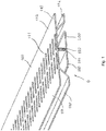
figure 1 est un dessin schématique d'une vue de dessus en perspective d'un mode de réalisation d'une grille de ventilation conforme à l'invention ; - La
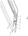
figure 2 est un dessin schématique d'une vue de dessous en perspective de la grille de ventilation de lafigure 1 ; - La
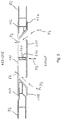
figure 3 est un dessin schématique d'une vue en coupe de la grille de ventilation en position entre deux panneaux à esthétique lambrissée ; - La
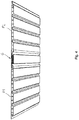
figure 4 est un dessin schématique d'une vue de dessous en perspective de la grille en position entre deux panneaux à esthétique lambrissée ; - La
figure 5 est un dessin schématique d'une vue de dessus en perspective de la grille en position entre deux panneaux à esthétique lambrissée. - Selon le mode de réalisation illustré par l'ensemble des figures, la grille de ventilation référencée G dans son ensemble est un élément linéaire profilé en PVC adoptant une structure symétrique selon un plan de symétrie longitudinal.
- Comme illustrée sur les dessins des
figures 1 et2 , la grille de ventilation G est en deux parties : - un corps 100 comprenant une surface 110 disposée en retrait située au-dessus sur la
figure 1 ) qui est trouée d'orifices 111 pour laisser passer l'air, et - un capotage 200 se plaçant devant (au-dessous sur la
figure 1 ) la surface trouée 110. - Ladite surface en retrait 110 est préformée dans sa partie centrale d'une projection longitudinale perpendiculaire formant nervure 120 avec laquelle vient coopérer le capotage 200.
- La face arrière du capotage 200 est préformée d'une projection longitudinale 210 formant nervure ménagée d'une rainure de façon à ce que les bords de la rainure se positionnent de part et d'autre de la languette 120 venant s'introduire dans ladite rainure 210 lors de l'installation du capotage 200 sur le corps 100.
- Cette liaison entre le corps et le capotage autorise le réglage de la position du capotage selon la flèche F1. On comprend en regard du dessin de la
figure 3 où l'air est symbolisé par les flèches F qu'un tel réglage de position permet le réglage de l'étranglement formé entre le capotage 200 et le corps 100. Les rebords du capot sont en outre repliés vers le corps afin de participer à l'effet esthétique recherché. - Comme illustré, ledit corps 100 adopte un profil symétrique s'évasant vers l'avant à partir de la surface en retrait trouée 110, le capotage 200 étant préformé d'une portion plane 220 d'occultation de largeur sensiblement égale à celle de la surface trouée 110. Il apparaît également que cette largeur correspond à celle des portions centrales planes des lames adjacentes.
- Comme illustrée, la surface trouée 110 se prolonge de chaque côté par des portions latérales coplanaires 112 et 113 arrière non trouées venant prendre appui sur les faces arrière des bords des lames ou panneaux adjacents P1 et P2, le profil s'évasant vers l'avant de part et d'autre de la surface trouée 110 se prolongeant par des portions latérales avant 114 et 115 parallèles aux portions latérale arrière et venant prendre appui sur les surfaces avant des bords des lames ou panneaux adjacents P1 et P2.
- Selon le mode de réalisation illustré, ladite grille G adopte sensiblement la même épaisseur que les lames ou panneaux auxquelles elle s'associe. La surface trouée 110 est sensiblement coplanaire avec les surfaces arrière des lames ou panneaux adjacents P1 et P2.
- Comme illustrée, la portion plane d'occultation 220 est positionnée sensiblement de façon à être coplanaire avec la surface avant des lames ou panneaux adjacents P1 et P2 formant une surface lambrissée à ventiler.
- La grille de ventilation G de l'invention permet ainsi d'obtenir le résultat illustré par les dessins des
figures 4 et5 , où la grille G est quasiment invisible tout en garantissant la fonction de ventilation avec des trous faisant communiquer l'avant et l'arrière de la surface lambrissée. - Ainsi, l'esthétique lambrissée est respectée et la présence d'une grille de ventilation ne constitue plus une zone plus sombre en discontinuité du reste du parement.
- On comprend que la grille de ventilation pour surface lambrissée, qui vient d'être ci-dessus décrite et représentée, l'a été en vue d'une divulgation plutôt que d'une limitation. Bien entendu, divers aménagements, modifications et améliorations pourront être apportés à l'exemple ci-dessus, sans pour autant sortir du cadre de l'invention.
Claims (10)
- Grille de ventilation (G) comprenant une lame trouée dont les bords sont préformés pour venir se fixer aux bords d'autres lames ou panneaux adjacents (P1 et P2) formant une surface lambrissée, ladite surface lambrissée étant formée extérieurement par la succession des surfaces avant coplanaires desdits autres lames ou panneaux (P1 et P2),
CARACTÉRISÉE PAR LE FAIT QU'elle comprend :- un corps (100) comprenant une surface (110) disposée en retrait par rapport aux surfaces avant des autres lames ou panneaux, laquelle surface en retrait est trouée pour laisser passer l'air, et- un capotage (200) disposé devant la surface trouée (110) avec une face avant positionnée sensiblement coplanaire avec les surfaces avant des autres lames ou panneaux. - Grille de ventilation (G) selon la revendication 1, CARACTÉRISÉE PAR LE FAIT QU'elle est en deux parties, le capotage (200) venant se fixer sur le corps (100).
- Grille de ventilation (G) selon la revendication 2, CARACTÉRISÉE PAR LE FAIT QUE ladite surface en retrait (110) est préformée d'une projection longitudinale perpendiculaire formant languette (120) avec laquelle vient coopérer le capotage (200).
- Grille de ventilation (G) selon la revendication 3, CARACTÉRISÉE PAR LE FAIT la face arrière du capotage (200) est préformée d'une projection longitudinale formant une nervure (210) qui est préformée d'une rainure dans laquelle vient s'introduire dans ladite languette (120).
- Grille de ventilation (G) selon la revendication 2, CARACTÉRISÉE PAR LE FAIT QUE la liaison entre le corps (100) et le capotage (200) autorise le réglage de la position du capotage (200).
- Grille de ventilation (G) selon la revendication 1, CARACTÉRISÉE PAR LE FAIT QUE ledit corps (100) adopte un profil s'évasant vers l'avant à partir de la surface en retrait trouée (110), le capotage (200) étant préformé d'une portion plane (220) de largeur sensiblement égale à celle de la surface trouée (110).
- Grille de ventilation (G) selon la revendication 6, CARACTÉRISÉE PAR LE FAIT QUE la surface trouée (110) se prolonge de chaque côté par des portions latérales coplanaires (112, 113) arrière non trouées venant prendre appui sur les faces arrière des bords des lames ou panneaux adjacents (P1 et P2), le profil s'évasant vers l'avant de part et d'autre de la surface trouée se prolongeant par des portions latérales avant (114, 115) parallèles aux portions latérales arrière (112, 113) et venant prendre appui sur les faces avant des bords des lames ou panneaux adjacents (P1 et P2).
- Grille de ventilation (G) selon la revendication 3, CARACTÉRISÉE PAR LE FAIT QUE ladite languette (120) est disposée au centre de ladite surface en retrait (110) laquelle est trouée de part et d'autre de ladite languette (120).
- Grille de ventilation (G) selon l'une quelconque des revendication 1 à 8, CARACTÉRISÉE PAR LE FAIT QU'elle est réalisée ainsi que les lames ou panneaux adjacents (P1 et P2) formant la surface lambrissée, dans le même matériau plastique.
- Procédé de fabrication d'une grille de ventilation (G) selon l'une quelconque des revendications 1 à 8, CARACTÉRISÉ PAR LE FAIT QU'il comprend les opérations suivantes :- extrusion du corps (100) en PVC non troué avec préformation d'une languette centrale,- extrusion du capotage (200) en PVC,- perçage de la surface en retrait (110) par poinçonnage,- assemblage du capotage (200) sur le corps (100).
Applications Claiming Priority (1)
| Application Number | Priority Date | Filing Date | Title |
|---|---|---|---|
| FR1852914A FR3079858B1 (fr) | 2018-04-04 | 2018-04-04 | Grille de ventilation d’une surface lambrissee et son procede de fabrication |
Publications (2)
| Publication Number | Publication Date |
|---|---|
| EP3550091A1 true EP3550091A1 (fr) | 2019-10-09 |
| EP3550091B1 EP3550091B1 (fr) | 2023-08-02 |
Family
ID=62873480
Family Applications (1)
| Application Number | Title | Priority Date | Filing Date |
|---|---|---|---|
| EP19167249.2A Active EP3550091B1 (fr) | 2018-04-04 | 2019-04-04 | Surface lambrissée comprenant une grille de ventilation, et procédé de fabrication de ladite grille |
Country Status (5)
| Country | Link |
|---|---|
| EP (1) | EP3550091B1 (fr) |
| ES (1) | ES2961718T3 (fr) |
| FR (1) | FR3079858B1 (fr) |
| PL (1) | PL3550091T3 (fr) |
| PT (1) | PT3550091T (fr) |
Citations (3)
| Publication number | Priority date | Publication date | Assignee | Title |
|---|---|---|---|---|
| US2949981A (en) * | 1957-12-17 | 1960-08-23 | Robertson Co H H | Wall structure |
| WO1985003965A1 (fr) * | 1984-02-28 | 1985-09-12 | Bruce Capper | Montages de support |
| JPH0886028A (ja) * | 1994-07-22 | 1996-04-02 | Matsushita Electric Works Ltd | 軒先通気部の防火構造 |
-
2018
- 2018-04-04 FR FR1852914A patent/FR3079858B1/fr active Active
-
2019
- 2019-04-04 EP EP19167249.2A patent/EP3550091B1/fr active Active
- 2019-04-04 ES ES19167249T patent/ES2961718T3/es active Active
- 2019-04-04 PT PT191672492T patent/PT3550091T/pt unknown
- 2019-04-04 PL PL19167249.2T patent/PL3550091T3/pl unknown
Patent Citations (3)
| Publication number | Priority date | Publication date | Assignee | Title |
|---|---|---|---|---|
| US2949981A (en) * | 1957-12-17 | 1960-08-23 | Robertson Co H H | Wall structure |
| WO1985003965A1 (fr) * | 1984-02-28 | 1985-09-12 | Bruce Capper | Montages de support |
| JPH0886028A (ja) * | 1994-07-22 | 1996-04-02 | Matsushita Electric Works Ltd | 軒先通気部の防火構造 |
Also Published As
| Publication number | Publication date |
|---|---|
| PT3550091T (pt) | 2023-11-06 |
| EP3550091B1 (fr) | 2023-08-02 |
| PL3550091T3 (pl) | 2024-01-22 |
| FR3079858B1 (fr) | 2020-06-19 |
| FR3079858A1 (fr) | 2019-10-11 |
| ES2961718T3 (es) | 2024-03-13 |
Similar Documents
| Publication | Publication Date | Title |
|---|---|---|
| USD970713S1 (en) | Ceiling fan | |
| USD961755S1 (en) | Ceiling fan | |
| USD966488S1 (en) | Ceiling fan | |
| USD949316S1 (en) | Ceiling fan | |
| USD1016335S1 (en) | Door component extrusion assembly | |
| USD1005473S1 (en) | Ceiling fan | |
| EP0365395B1 (fr) | Dispositif d'extraction d'air pour un véhicule automobile | |
| USD1016720S1 (en) | Vehicle awning | |
| EP3891349A1 (fr) | Panneau a assemblage vertical pour la realisation d'un revêtement | |
| USD887987S1 (en) | Connector housing | |
| EP1580077A1 (fr) | Elément d'habillage, notamment pour intérieur d'automobile, et son procédé de fabrication | |
| USD904990S1 (en) | Conductive sticker | |
| USD917729S1 (en) | Window component extrusion | |
| USD1054066S1 (en) | Door component extrusion assembly | |
| USD921929S1 (en) | Window component extrusion | |
| EP3550091B1 (fr) | Surface lambrissée comprenant une grille de ventilation, et procédé de fabrication de ladite grille | |
| FR2779398A1 (fr) | Garnissage de plafond avec haut-parleur plat integre | |
| EP3044390B1 (fr) | Systeme de fixation pour la réalisation de revêtements tendus | |
| USD1095898S1 (en) | Solar string light set | |
| USD1052008S1 (en) | Model vehicle window assembly | |
| USD1053388S1 (en) | Door component extrusion assembly | |
| USD1054065S1 (en) | Door component extrusion assembly | |
| EP0065914B1 (fr) | Profilés pour bardages isolés à trame croisée | |
| FR3032997A1 (fr) | Lame de decoration d’une menuiserie et son procede de fabrication | |
| FR3057593A1 (fr) | Dispositif de liaison des extremites de lames de bardage |
Legal Events
| Date | Code | Title | Description |
|---|---|---|---|
| PUAI | Public reference made under article 153(3) epc to a published international application that has entered the european phase |
Free format text: ORIGINAL CODE: 0009012 |
|
| STAA | Information on the status of an ep patent application or granted ep patent |
Free format text: STATUS: THE APPLICATION HAS BEEN PUBLISHED |
|
| AK | Designated contracting states |
Kind code of ref document: A1 Designated state(s): AL AT BE BG CH CY CZ DE DK EE ES FI FR GB GR HR HU IE IS IT LI LT LU LV MC MK MT NL NO PL PT RO RS SE SI SK SM TR |
|
| AX | Request for extension of the european patent |
Extension state: BA ME |
|
| STAA | Information on the status of an ep patent application or granted ep patent |
Free format text: STATUS: REQUEST FOR EXAMINATION WAS MADE |
|
| 17P | Request for examination filed |
Effective date: 20200408 |
|
| RBV | Designated contracting states (corrected) |
Designated state(s): AL AT BE BG CH CY CZ DE DK EE ES FI FR GB GR HR HU IE IS IT LI LT LU LV MC MK MT NL NO PL PT RO RS SE SI SK SM TR |
|
| STAA | Information on the status of an ep patent application or granted ep patent |
Free format text: STATUS: EXAMINATION IS IN PROGRESS |
|
| 17Q | First examination report despatched |
Effective date: 20220502 |
|
| GRAP | Despatch of communication of intention to grant a patent |
Free format text: ORIGINAL CODE: EPIDOSNIGR1 |
|
| STAA | Information on the status of an ep patent application or granted ep patent |
Free format text: STATUS: GRANT OF PATENT IS INTENDED |
|
| INTG | Intention to grant announced |
Effective date: 20230113 |
|
| GRAS | Grant fee paid |
Free format text: ORIGINAL CODE: EPIDOSNIGR3 |
|
| GRAA | (expected) grant |
Free format text: ORIGINAL CODE: 0009210 |
|
| STAA | Information on the status of an ep patent application or granted ep patent |
Free format text: STATUS: THE PATENT HAS BEEN GRANTED |
|
| AK | Designated contracting states |
Kind code of ref document: B1 Designated state(s): AL AT BE BG CH CY CZ DE DK EE ES FI FR GB GR HR HU IE IS IT LI LT LU LV MC MK MT NL NO PL PT RO RS SE SI SK SM TR |
|
| REG | Reference to a national code |
Ref country code: GB Ref legal event code: FG4D Free format text: NOT ENGLISH |
|
| REG | Reference to a national code |
Ref country code: CH Ref legal event code: EP |
|
| REG | Reference to a national code |
Ref country code: DE Ref legal event code: R096 Ref document number: 602019033862 Country of ref document: DE |
|
| REG | Reference to a national code |
Ref country code: IE Ref legal event code: FG4D Free format text: LANGUAGE OF EP DOCUMENT: FRENCH |
|
| REG | Reference to a national code |
Ref country code: PT Ref legal event code: SC4A Ref document number: 3550091 Country of ref document: PT Date of ref document: 20231106 Kind code of ref document: T Free format text: AVAILABILITY OF NATIONAL TRANSLATION Effective date: 20231027 |
|
| REG | Reference to a national code |
Ref country code: NL Ref legal event code: FP |
|
| REG | Reference to a national code |
Ref country code: LT Ref legal event code: MG9D |
|
| REG | Reference to a national code |
Ref country code: AT Ref legal event code: MK05 Ref document number: 1594916 Country of ref document: AT Kind code of ref document: T Effective date: 20230802 |
|
| PG25 | Lapsed in a contracting state [announced via postgrant information from national office to epo] |
Ref country code: GR Free format text: LAPSE BECAUSE OF FAILURE TO SUBMIT A TRANSLATION OF THE DESCRIPTION OR TO PAY THE FEE WITHIN THE PRESCRIBED TIME-LIMIT Effective date: 20231103 |
|
| PG25 | Lapsed in a contracting state [announced via postgrant information from national office to epo] |
Ref country code: IS Free format text: LAPSE BECAUSE OF FAILURE TO SUBMIT A TRANSLATION OF THE DESCRIPTION OR TO PAY THE FEE WITHIN THE PRESCRIBED TIME-LIMIT Effective date: 20231202 |
|
| PG25 | Lapsed in a contracting state [announced via postgrant information from national office to epo] |
Ref country code: SE Free format text: LAPSE BECAUSE OF FAILURE TO SUBMIT A TRANSLATION OF THE DESCRIPTION OR TO PAY THE FEE WITHIN THE PRESCRIBED TIME-LIMIT Effective date: 20230802 Ref country code: RS Free format text: LAPSE BECAUSE OF FAILURE TO SUBMIT A TRANSLATION OF THE DESCRIPTION OR TO PAY THE FEE WITHIN THE PRESCRIBED TIME-LIMIT Effective date: 20230802 Ref country code: NO Free format text: LAPSE BECAUSE OF FAILURE TO SUBMIT A TRANSLATION OF THE DESCRIPTION OR TO PAY THE FEE WITHIN THE PRESCRIBED TIME-LIMIT Effective date: 20231102 Ref country code: LV Free format text: LAPSE BECAUSE OF FAILURE TO SUBMIT A TRANSLATION OF THE DESCRIPTION OR TO PAY THE FEE WITHIN THE PRESCRIBED TIME-LIMIT Effective date: 20230802 Ref country code: LT Free format text: LAPSE BECAUSE OF FAILURE TO SUBMIT A TRANSLATION OF THE DESCRIPTION OR TO PAY THE FEE WITHIN THE PRESCRIBED TIME-LIMIT Effective date: 20230802 Ref country code: IS Free format text: LAPSE BECAUSE OF FAILURE TO SUBMIT A TRANSLATION OF THE DESCRIPTION OR TO PAY THE FEE WITHIN THE PRESCRIBED TIME-LIMIT Effective date: 20231202 Ref country code: HR Free format text: LAPSE BECAUSE OF FAILURE TO SUBMIT A TRANSLATION OF THE DESCRIPTION OR TO PAY THE FEE WITHIN THE PRESCRIBED TIME-LIMIT Effective date: 20230802 Ref country code: GR Free format text: LAPSE BECAUSE OF FAILURE TO SUBMIT A TRANSLATION OF THE DESCRIPTION OR TO PAY THE FEE WITHIN THE PRESCRIBED TIME-LIMIT Effective date: 20231103 Ref country code: FI Free format text: LAPSE BECAUSE OF FAILURE TO SUBMIT A TRANSLATION OF THE DESCRIPTION OR TO PAY THE FEE WITHIN THE PRESCRIBED TIME-LIMIT Effective date: 20230802 Ref country code: AT Free format text: LAPSE BECAUSE OF FAILURE TO SUBMIT A TRANSLATION OF THE DESCRIPTION OR TO PAY THE FEE WITHIN THE PRESCRIBED TIME-LIMIT Effective date: 20230802 |
|
| REG | Reference to a national code |
Ref country code: ES Ref legal event code: FG2A Ref document number: 2961718 Country of ref document: ES Kind code of ref document: T3 Effective date: 20240313 |
|
| PG25 | Lapsed in a contracting state [announced via postgrant information from national office to epo] |
Ref country code: SM Free format text: LAPSE BECAUSE OF FAILURE TO SUBMIT A TRANSLATION OF THE DESCRIPTION OR TO PAY THE FEE WITHIN THE PRESCRIBED TIME-LIMIT Effective date: 20230802 Ref country code: RO Free format text: LAPSE BECAUSE OF FAILURE TO SUBMIT A TRANSLATION OF THE DESCRIPTION OR TO PAY THE FEE WITHIN THE PRESCRIBED TIME-LIMIT Effective date: 20230802 Ref country code: EE Free format text: LAPSE BECAUSE OF FAILURE TO SUBMIT A TRANSLATION OF THE DESCRIPTION OR TO PAY THE FEE WITHIN THE PRESCRIBED TIME-LIMIT Effective date: 20230802 Ref country code: DK Free format text: LAPSE BECAUSE OF FAILURE TO SUBMIT A TRANSLATION OF THE DESCRIPTION OR TO PAY THE FEE WITHIN THE PRESCRIBED TIME-LIMIT Effective date: 20230802 Ref country code: CZ Free format text: LAPSE BECAUSE OF FAILURE TO SUBMIT A TRANSLATION OF THE DESCRIPTION OR TO PAY THE FEE WITHIN THE PRESCRIBED TIME-LIMIT Effective date: 20230802 Ref country code: SK Free format text: LAPSE BECAUSE OF FAILURE TO SUBMIT A TRANSLATION OF THE DESCRIPTION OR TO PAY THE FEE WITHIN THE PRESCRIBED TIME-LIMIT Effective date: 20230802 |
|
| REG | Reference to a national code |
Ref country code: DE Ref legal event code: R097 Ref document number: 602019033862 Country of ref document: DE |
|
| PG25 | Lapsed in a contracting state [announced via postgrant information from national office to epo] |
Ref country code: IT Free format text: LAPSE BECAUSE OF FAILURE TO SUBMIT A TRANSLATION OF THE DESCRIPTION OR TO PAY THE FEE WITHIN THE PRESCRIBED TIME-LIMIT Effective date: 20230802 |
|
| PLBE | No opposition filed within time limit |
Free format text: ORIGINAL CODE: 0009261 |
|
| STAA | Information on the status of an ep patent application or granted ep patent |
Free format text: STATUS: NO OPPOSITION FILED WITHIN TIME LIMIT |
|
| 26N | No opposition filed |
Effective date: 20240503 |
|
| PG25 | Lapsed in a contracting state [announced via postgrant information from national office to epo] |
Ref country code: SI Free format text: LAPSE BECAUSE OF FAILURE TO SUBMIT A TRANSLATION OF THE DESCRIPTION OR TO PAY THE FEE WITHIN THE PRESCRIBED TIME-LIMIT Effective date: 20230802 |
|
| PG25 | Lapsed in a contracting state [announced via postgrant information from national office to epo] |
Ref country code: BG Free format text: LAPSE BECAUSE OF FAILURE TO SUBMIT A TRANSLATION OF THE DESCRIPTION OR TO PAY THE FEE WITHIN THE PRESCRIBED TIME-LIMIT Effective date: 20230802 |
|
| PG25 | Lapsed in a contracting state [announced via postgrant information from national office to epo] |
Ref country code: BG Free format text: LAPSE BECAUSE OF FAILURE TO SUBMIT A TRANSLATION OF THE DESCRIPTION OR TO PAY THE FEE WITHIN THE PRESCRIBED TIME-LIMIT Effective date: 20230802 |
|
| PG25 | Lapsed in a contracting state [announced via postgrant information from national office to epo] |
Ref country code: LU Free format text: LAPSE BECAUSE OF NON-PAYMENT OF DUE FEES Effective date: 20240404 |
|
| PG25 | Lapsed in a contracting state [announced via postgrant information from national office to epo] |
Ref country code: LU Free format text: LAPSE BECAUSE OF NON-PAYMENT OF DUE FEES Effective date: 20240404 |
|
| PG25 | Lapsed in a contracting state [announced via postgrant information from national office to epo] |
Ref country code: CY Free format text: LAPSE BECAUSE OF FAILURE TO SUBMIT A TRANSLATION OF THE DESCRIPTION OR TO PAY THE FEE WITHIN THE PRESCRIBED TIME-LIMIT; INVALID AB INITIO Effective date: 20190404 |
|
| PG25 | Lapsed in a contracting state [announced via postgrant information from national office to epo] |
Ref country code: HU Free format text: LAPSE BECAUSE OF FAILURE TO SUBMIT A TRANSLATION OF THE DESCRIPTION OR TO PAY THE FEE WITHIN THE PRESCRIBED TIME-LIMIT; INVALID AB INITIO Effective date: 20190404 |
|
| PG25 | Lapsed in a contracting state [announced via postgrant information from national office to epo] |
Ref country code: TR Free format text: LAPSE BECAUSE OF FAILURE TO SUBMIT A TRANSLATION OF THE DESCRIPTION OR TO PAY THE FEE WITHIN THE PRESCRIBED TIME-LIMIT Effective date: 20230802 |
|
| PGFP | Annual fee paid to national office [announced via postgrant information from national office to epo] |
Ref country code: PT Payment date: 20260331 Year of fee payment: 8 |
|
| REG | Reference to a national code |
Ref country code: CH Ref legal event code: U11 Free format text: ST27 STATUS EVENT CODE: U-0-0-U10-U11 (AS PROVIDED BY THE NATIONAL OFFICE) Effective date: 20260501 |
|
| PGFP | Annual fee paid to national office [announced via postgrant information from national office to epo] |
Ref country code: NL Payment date: 20260426 Year of fee payment: 8 |
|
| PGFP | Annual fee paid to national office [announced via postgrant information from national office to epo] |
Ref country code: ES Payment date: 20260504 Year of fee payment: 8 |
|
| PGFP | Annual fee paid to national office [announced via postgrant information from national office to epo] |
Ref country code: PL Payment date: 20260505 Year of fee payment: 8 Ref country code: GB Payment date: 20260427 Year of fee payment: 8 |
|
| PGFP | Annual fee paid to national office [announced via postgrant information from national office to epo] |
Ref country code: MC Payment date: 20260413 Year of fee payment: 8 |
|
| PGFP | Annual fee paid to national office [announced via postgrant information from national office to epo] |
Ref country code: DE Payment date: 20260429 Year of fee payment: 8 |
|
| PGFP | Annual fee paid to national office [announced via postgrant information from national office to epo] |
Ref country code: CH Payment date: 20260501 Year of fee payment: 8 Ref country code: BE Payment date: 20260427 Year of fee payment: 8 Ref country code: IE Payment date: 20260427 Year of fee payment: 8 |
|
| PGFP | Annual fee paid to national office [announced via postgrant information from national office to epo] |
Ref country code: FR Payment date: 20260428 Year of fee payment: 8 |