EP3550059A1 - Electrospinning apparatus - Google Patents
Electrospinning apparatus Download PDFInfo
- Publication number
- EP3550059A1 EP3550059A1 EP17847719.6A EP17847719A EP3550059A1 EP 3550059 A1 EP3550059 A1 EP 3550059A1 EP 17847719 A EP17847719 A EP 17847719A EP 3550059 A1 EP3550059 A1 EP 3550059A1
- Authority
- EP
- European Patent Office
- Prior art keywords
- collector
- nozzle
- nozzle head
- source material
- material liquid
- Prior art date
- Legal status (The legal status is an assumption and is not a legal conclusion. Google has not performed a legal analysis and makes no representation as to the accuracy of the status listed.)
- Pending
Links
Images




Classifications
-
- D—TEXTILES; PAPER
- D01—NATURAL OR MAN-MADE THREADS OR FIBRES; SPINNING
- D01D—MECHANICAL METHODS OR APPARATUS IN THE MANUFACTURE OF ARTIFICIAL FILAMENTS, THREADS, FIBRES, BRISTLES OR RIBBONS
- D01D5/00—Formation of filaments, threads, or the like
- D01D5/0007—Electro-spinning
- D01D5/0061—Electro-spinning characterised by the electro-spinning apparatus
-
- D—TEXTILES; PAPER
- D01—NATURAL OR MAN-MADE THREADS OR FIBRES; SPINNING
- D01D—MECHANICAL METHODS OR APPARATUS IN THE MANUFACTURE OF ARTIFICIAL FILAMENTS, THREADS, FIBRES, BRISTLES OR RIBBONS
- D01D5/00—Formation of filaments, threads, or the like
- D01D5/0007—Electro-spinning
- D01D5/0061—Electro-spinning characterised by the electro-spinning apparatus
- D01D5/0069—Electro-spinning characterised by the electro-spinning apparatus characterised by the spinning section, e.g. capillary tube, protrusion or pin
-
- D—TEXTILES; PAPER
- D01—NATURAL OR MAN-MADE THREADS OR FIBRES; SPINNING
- D01D—MECHANICAL METHODS OR APPARATUS IN THE MANUFACTURE OF ARTIFICIAL FILAMENTS, THREADS, FIBRES, BRISTLES OR RIBBONS
- D01D4/00—Spinnerette packs; Cleaning thereof
- D01D4/04—Cleaning spinnerettes or other parts of the spinnerette packs
-
- D—TEXTILES; PAPER
- D01—NATURAL OR MAN-MADE THREADS OR FIBRES; SPINNING
- D01D—MECHANICAL METHODS OR APPARATUS IN THE MANUFACTURE OF ARTIFICIAL FILAMENTS, THREADS, FIBRES, BRISTLES OR RIBBONS
- D01D5/00—Formation of filaments, threads, or the like
- D01D5/0007—Electro-spinning
- D01D5/0061—Electro-spinning characterised by the electro-spinning apparatus
- D01D5/0076—Electro-spinning characterised by the electro-spinning apparatus characterised by the collecting device, e.g. drum, wheel, endless belt, plate or grid
-
- D—TEXTILES; PAPER
- D04—BRAIDING; LACE-MAKING; KNITTING; TRIMMINGS; NON-WOVEN FABRICS
- D04H—MAKING TEXTILE FABRICS, e.g. FROM FIBRES OR FILAMENTARY MATERIAL; FABRICS MADE BY SUCH PROCESSES OR APPARATUS, e.g. FELTS, NON-WOVEN FABRICS; COTTON-WOOL; WADDING ; NON-WOVEN FABRICS FROM STAPLE FIBRES, FILAMENTS OR YARNS, BONDED WITH AT LEAST ONE WEB-LIKE MATERIAL DURING THEIR CONSOLIDATION
- D04H1/00—Non-woven fabrics formed wholly or mainly of staple fibres or like relatively short fibres
- D04H1/70—Non-woven fabrics formed wholly or mainly of staple fibres or like relatively short fibres characterised by the method of forming fleeces or layers, e.g. reorientation of fibres
- D04H1/72—Non-woven fabrics formed wholly or mainly of staple fibres or like relatively short fibres characterised by the method of forming fleeces or layers, e.g. reorientation of fibres the fibres being randomly arranged
- D04H1/728—Non-woven fabrics formed wholly or mainly of staple fibres or like relatively short fibres characterised by the method of forming fleeces or layers, e.g. reorientation of fibres the fibres being randomly arranged by electro-spinning
-
- D—TEXTILES; PAPER
- D01—NATURAL OR MAN-MADE THREADS OR FIBRES; SPINNING
- D01D—MECHANICAL METHODS OR APPARATUS IN THE MANUFACTURE OF ARTIFICIAL FILAMENTS, THREADS, FIBRES, BRISTLES OR RIBBONS
- D01D5/00—Formation of filaments, threads, or the like
- D01D5/0007—Electro-spinning
- D01D5/0015—Electro-spinning characterised by the initial state of the material
- D01D5/003—Electro-spinning characterised by the initial state of the material the material being a polymer solution or dispersion
- D01D5/0038—Electro-spinning characterised by the initial state of the material the material being a polymer solution or dispersion the fibre formed by solvent evaporation, i.e. dry electro-spinning
-
- D—TEXTILES; PAPER
- D01—NATURAL OR MAN-MADE THREADS OR FIBRES; SPINNING
- D01D—MECHANICAL METHODS OR APPARATUS IN THE MANUFACTURE OF ARTIFICIAL FILAMENTS, THREADS, FIBRES, BRISTLES OR RIBBONS
- D01D5/00—Formation of filaments, threads, or the like
- D01D5/0007—Electro-spinning
- D01D5/0061—Electro-spinning characterised by the electro-spinning apparatus
- D01D5/0076—Electro-spinning characterised by the electro-spinning apparatus characterised by the collecting device, e.g. drum, wheel, endless belt, plate or grid
- D01D5/0084—Coating by electro-spinning, i.e. the electro-spun fibres are not removed from the collecting device but remain integral with it, e.g. coating of prostheses
-
- D—TEXTILES; PAPER
- D04—BRAIDING; LACE-MAKING; KNITTING; TRIMMINGS; NON-WOVEN FABRICS
- D04H—MAKING TEXTILE FABRICS, e.g. FROM FIBRES OR FILAMENTARY MATERIAL; FABRICS MADE BY SUCH PROCESSES OR APPARATUS, e.g. FELTS, NON-WOVEN FABRICS; COTTON-WOOL; WADDING ; NON-WOVEN FABRICS FROM STAPLE FIBRES, FILAMENTS OR YARNS, BONDED WITH AT LEAST ONE WEB-LIKE MATERIAL DURING THEIR CONSOLIDATION
- D04H1/00—Non-woven fabrics formed wholly or mainly of staple fibres or like relatively short fibres
- D04H1/40—Non-woven fabrics formed wholly or mainly of staple fibres or like relatively short fibres from fleeces or layers composed of fibres without existing or potential cohesive properties
- D04H1/42—Non-woven fabrics formed wholly or mainly of staple fibres or like relatively short fibres from fleeces or layers composed of fibres without existing or potential cohesive properties characterised by the use of certain kinds of fibres insofar as this use has no preponderant influence on the consolidation of the fleece
- D04H1/4209—Inorganic fibres
- D04H1/4242—Carbon fibres
-
- D—TEXTILES; PAPER
- D04—BRAIDING; LACE-MAKING; KNITTING; TRIMMINGS; NON-WOVEN FABRICS
- D04H—MAKING TEXTILE FABRICS, e.g. FROM FIBRES OR FILAMENTARY MATERIAL; FABRICS MADE BY SUCH PROCESSES OR APPARATUS, e.g. FELTS, NON-WOVEN FABRICS; COTTON-WOOL; WADDING ; NON-WOVEN FABRICS FROM STAPLE FIBRES, FILAMENTS OR YARNS, BONDED WITH AT LEAST ONE WEB-LIKE MATERIAL DURING THEIR CONSOLIDATION
- D04H1/00—Non-woven fabrics formed wholly or mainly of staple fibres or like relatively short fibres
- D04H1/40—Non-woven fabrics formed wholly or mainly of staple fibres or like relatively short fibres from fleeces or layers composed of fibres without existing or potential cohesive properties
- D04H1/54—Non-woven fabrics formed wholly or mainly of staple fibres or like relatively short fibres from fleeces or layers composed of fibres without existing or potential cohesive properties by welding together the fibres, e.g. by partially melting or dissolving
- D04H1/542—Adhesive fibres
- D04H1/55—Polyesters
Definitions
- An embodiment of the invention relates to an electrospinning apparatus.
- electrospinning apparatus that deposits a fine fiber on the surface of a member by electrospinning (also called electric field spinning, charge-induced spinning, etc.).
- a nozzle head that includes multiple nozzles discharging a source material liquid is provided in the electrospinning apparatus.
- an electrospinning apparatus including a nozzle head and a member having a band configuration has been proposed.
- the member and the nozzle head are provided to oppose each other.
- the fiber is deposited on the surface of the member having the band configuration while moving the member having the band configuration.
- the production amount of the deposited body per unit time or per unit surface area can be increased by increasing the number of nozzle heads.
- the number of nozzle heads is simply increased, this may cause an enlargement of the electrospinning apparatus.
- a problem to be solved by the invention is to provide an electrospinning apparatus in which improvement of the productivity and better space conservation can be realized.
- An electrospinning apparatus is configured to deposit a fiber on a collector or a member.
- the electrospinning apparatus includes a first nozzle head provided on one side of the collector or the member, and a second nozzle head provided on the side opposite to the first nozzle head with the collector or the member interposed.
- An electrospinning apparatus 1 that includes a so-called needle-type nozzle head will now be illustrated as an example.
- the configuration of the nozzle provided in the nozzle head is not limited to a needle-like configuration.
- the nozzle that is provided in the nozzle head may be a nozzle having a circular conic configuration, etc.
- a nozzle having a needle-like configuration if used, electric field concentration occurs easily at the vicinity of the outlet of the nozzle; therefore, the strength of the electric field generated between the nozzle and the collector becomes high.
- the mechanical strength of the nozzle can be increased.
- the tip of the nozzle having the circular conic configuration can be sharp, the strength of the electric field generated between the nozzle and the collector becomes high similarly to the nozzle having the needle-like configuration.
- the nozzle head may be a so-called blade-type nozzle head, etc. If a blade-type nozzle head is used, the mechanical strength can be increased; therefore, damage of the nozzle head when cleaning, etc., can be suppressed. Also, the cleaning of the nozzle head is easy.
- the configuration of the blade-type nozzle head is not particularly limited and may be, for example, a rectangular parallelepiped configuration or a circular arc-like configuration.
- FIG. 1 is a schematic view for illustrating the electrospinning apparatus 1 according to a first embodiment.
- a first nozzle head 2a, a second nozzle head 2b, a source material liquid supplier 3, a power supply 4, a collector 5, and a controller 6 are provided in the electrospinning apparatus 1.
- the first nozzle head 2a is provided on one side of the collector 5.
- the first nozzle head 2a is provided above the collector 5.
- the first nozzle head 2a opposes a first surface 5a of the collector 5.
- the second nozzle head 2b is provided on the side opposite to the first nozzle head 2a with the collector 5 interposed.
- the second nozzle head 2b is provided below the collector 5.
- the second nozzle head 2b opposes a second surface 5b of the collector 5 on the side opposite to the first surface 5a.
- the second nozzle head 2b opposes the first nozzle head 2a with the collector 5 interposed.
- the second nozzle head 2b is provided at a position overlapping the first nozzle head 2a.
- the first nozzle head 2a and the second nozzle head 2b include nozzles 20, connectors 21, and main parts 22.
- the nozzle 20 has a needle-like configuration.
- a hole for discharging the source material liquid is provided in the interior of the nozzle 20.
- the hole for discharging the source material liquid communicates between the end portion of the nozzle 20 on the connector 21 side and the end portion (the tip) of the nozzle 20 on the collector 5 side.
- the opening of the hole for discharging the source material liquid on the collector 5 side is an outlet 20a.
- the outer diameter dimension (in the case where the nozzle 20 has a cylindrical configuration, the diametrical dimension) of the nozzle 20 is not particularly limited, it is favorable for the outer diameter dimension to be small. If the outer diameter dimension is set to be small, electric field concentration occurs easily at the vicinity of the outlet 20a of the nozzle 20. If the electric field concentration occurs at the vicinity of the outlet 20a of the nozzle 20, the strength of the electric field generated between the nozzle 20 and the collector 5 can be increased compared to the case where the outer diameter dimension of the nozzle 20 is large. Therefore, the voltage that is applied by the power supply 5 can be set to be low compared to the case where the outer diameter dimension of the nozzle 20 is large. In other words, the drive voltage can be reduced compared to the case where the outer diameter dimension of the nozzle 20 is large. In such a case, for example, the outer diameter dimension of the nozzle 20 can be set to about 0.3 mm to 1.3 mm.
- the dimension (in the case where the outlet 20a is a circle, the diametrical dimension) of the outlet 20a is not particularly limited.
- the dimension of the outlet 20a can be modified appropriately according to the cross-sectional dimension of a fiber 100 to be formed.
- the dimension of the outlet 20a (the inner diameter dimension of the nozzle 20) can be set to about 0.1 mm to 1 mm.
- the nozzle 20 is formed from a conductive material. It is favorable for the material of the nozzle 20 to be conductive and to have resistance to the source material liquid described below.
- the nozzle 20 can be formed from stainless steel, etc.
- the number of the nozzles 20 is not particularly limited and can be modified appropriately according to the size of the collector 5, etc. It is sufficient for at least one nozzle 20 to be provided.
- the multiple nozzles 20 are provided to be arranged at a prescribed spacing.
- the multiple nozzles 20 can be provided to be arranged in a direction orthogonal to a movement direction 50 of the collector 5.
- the arrangement form of the multiple nozzles 20 is not particularly limited.
- the multiple nozzles 20 also can be provided to be arranged in one column, can be provided to be arranged in multiple columns, can be provided to be arranged on a circumference or on concentric circles, or can be provided to be arranged in a staggered configuration or a matrix configuration.
- the connector 21 is provided between the nozzle 20 and the main part 22.
- a hole for supplying the source material liquid from the main part 22 to the nozzle 20 is provided in the interior of the connector 21.
- the hole that is provided in the interior of the connector 21 communicates with the hole provided in the interior of the nozzle 20 and the space provided in the interior of the main part 22.
- the connector 21 is formed from a conductive material. It is favorable for the material of the connector 21 to be conductive and to have resistance to the source material liquid.
- the connector 21 can be formed from stainless steel, etc.
- the connector 21 In the case where the voltage is directly applied to the nozzle 20, it is not always necessary for the connector 21 to be formed from a conductive material.
- the connector 21 is not always necessary; and the nozzle 20 may be provided directly at the main part 22.
- the end portion of the nozzle 20 on the connector 21 side can be fixed to the connector 21; and the connector 21 can be provided detachably at the main part 22.
- an external-thread screw can be provided in the end portion of the connector 21 on the main part 22 side; and an internal-thread tap can be provided in the side surface of the main part 22.
- the connector 21 can be provided detachably at the main part 22 by using a luer taper (luer taper) (also called a luer adapter, a luer lock, a luer connector, a luer fit, etc.).
- a female luer female luer
- a male luer male luer
- the connector 21 may be connected to the main part 22 by using a screw or a luer taper.
- a space in which the source material liquid is stored is provided in the interior of the main part 22.
- the configuration of the main part 22 is not particularly limited, the main part 22 can have a rod configuration in the case where the multiple nozzles 20 are provided.
- the main part 22 that has the rod configuration can extend in a direction orthogonal to the movement direction 50 of the collector 5.
- the main part 22 that has the rod configuration can be provided to be parallel to the first surface 5a or the second surface 5b of the collector 5.
- a supply port 22a is provided in the main part 22.
- the source material liquid that is supplied from the source material liquid supplier 3 is introduced to the interior of the main part 22 via the supply port 22a.
- the number and the arrangement positions of the supply ports 22a are not particularly limited.
- the supply port 22a can be provided on the side opposite to the side where the nozzle 20 of the main part 22 is provided.
- the material of the main part 22 is conductive and to have resistance to the source material liquid.
- the main part 22 can be formed from stainless steel, etc.
- the source material liquid supplier 3 includes a container 31, a supplier 32, a source material liquid controller 33, and a pipe 34.
- the container 31 stores the source material liquid.
- the container 31 is formed from a material having resistance to the source material liquid.
- the container 31 can be formed from stainless steel, etc.
- the source material liquid is a polymeric substance dissolved in a solvent.
- the polymeric substance is not particularly limited and can be modified appropriately according to the material properties of the fiber 100 to be formed.
- the polymeric substance can be, for example, polypropylene, polyethylene, polystyrene, polyethylene terephthalate, polyvinyl chloride, polycarbonate, nylon, aramid, etc.
- the solvent can be modified appropriately according to the polymeric substance to be dissolved.
- the solvent can be, for example, methanol, ethanol, isopropyl alcohol, acetone, benzene, toluene, etc.
- the polymeric substance and the solvent are not limited to those illustrated.
- the source material liquid can be produced from a solvent and one type of polymeric substance, or can be produced by mixing a solvent and multiple types of polymeric substances.
- the source material liquid that is supplied to the first nozzle head 2a and the source material liquid that is supplied to the second nozzle head 2b may be of the same type; or the source material liquid that is supplied to the first nozzle head 2a and the source material liquid that is supplied to the second nozzle head 2b may be of different types.
- the source material liquid is caused to collect at the vicinity of the outlet 20a by surface tension.
- the viscosity of the source material liquid can be modified appropriately according to the dimension of the outlet 20a, etc.
- the viscosity of the source material liquid can be determined by performing experiments and/or simulations. Also, the viscosity of the source material liquid can be controlled by the mixture proportion of the solvent and the polymeric substance.
- the supplier 32 supplies the source material liquid stored in the container 31 to the main part 22.
- the supplier 32 can be, for example, a pump having resistance to the source material liquid, etc. Also, for example, the supplier 32 may feed the source material liquid stored in the container 31 by supplying a gas to the container 31.
- the source material liquid controller 33 controls the flow rate, the pressure, etc., of the source material liquid supplied to the main part 22 so that the source material liquid in the interior of the main part 22 is not pushed out from the outlet 20a when new source material liquid is supplied to the interior of the main part 22. In other words, the source material liquid is caused to collect at the vicinity of the outlet 20a by the surface tension.
- the control amount for the source material liquid controller 33 can be modified appropriately by the dimension of the outlet 20a, the viscosity of the source material liquid, etc.
- the control amount for the source material liquid controller 33 can be determined by performing experiments and/or simulations.
- the source material liquid controller 33 can be able to switch between the starting of the supply and the stopping of the supply of the source material liquid.
- the supplier 32 and the source material liquid controller 33 are not always necessary.
- the container 31 is provided at a position that is higher than the position of the main part 22, the source material liquid can be supplied to the main part 22 by utilizing gravity. Then, the source material liquid that is in the interior of the main part 22 can be caused not to be pushed out from the outlet 20a when the new source material liquid is supplied to the interior of the main part 22 by appropriately setting the height position of the container 31.
- the height position of the container 31 can be modified appropriately using the dimension of the outlet 20a, the viscosity of the source material liquid, etc.
- the height position of the container 31 can be determined by performing experiments and/or simulations.
- the pipe 34 is provided between the container 31 and the supplier 32, between the supplier 32 and the source material liquid controller 33, and between the source material liquid controller 33 and the main part 22.
- the pipe 34 is used as a flow channel of the source material liquid.
- the pipe 34 is formed from a material having resistance to the source material liquid.
- the power supply 4 applies the voltage to the nozzle 20 via the main part 22 and the connector 21. Not-illustrated terminals that are electrically connected to the nozzle 20 may be provided. In such a case, the power supply 4 applies the voltage to the nozzle 20 via the not-illustrated terminals. In other words, it is sufficient for the voltage to be able to be applied to the nozzle 20 from the power supply 4.
- the polarity of the voltage (the drive voltage) applied to the nozzle 20 can be set to be positive or set to be negative. However, if a negative voltage is applied to the nozzle 20, irregular electric discharge occurs easily because electrons are discharged from the tip of the nozzle 20. Therefore, as shown in FIG. 1 , it is favorable for the polarity of the voltage applied to the nozzle 20 to be positive.
- the voltage that is applied to the nozzle 20 can be modified appropriately according to the type of the polymeric substance included in the source material liquid, the distance between the nozzle 20 and the collector 5, etc.
- the power supply 4 can apply a voltage to the nozzle 20 so that the potential difference between the nozzle 20 and the collector 5 is 10 kV or more. In such a case, if a blade-type nozzle head is used, the voltage that is applied to the nozzle is about 70 kV. On the other hand, if a needle-type nozzle head such as that illustrated in FIG. 1 is used, the voltage that is applied to the nozzle 20 can be set to 50 kV or less. Therefore, a reduction of the drive voltage can be realized.
- the power supply 4 can be, for example, a direct current-high voltage power supply.
- the power supply 4 can output a direct current voltage of not less than 10 kV and not more than 100 kV.
- the electrospinning apparatus 1 illustrated in FIG. 1 supplies the source material liquid to the first nozzle head 2a and the second nozzle head 2b by one source material liquid supplier 3 and applies the voltage to the first nozzle head 2a and the second nozzle head 2b by one power supply 4.
- simplification of the configuration, better space conservation, a reduction of the manufacturing cost, etc., of the electrospinning apparatus 1 can be realized.
- one each of the source material liquid supplier 3 and the power supply 4 can be provided respectively for the first nozzle head 2a and the second nozzle head 2b.
- the control of the supply amount of the source material liquid and/or the control of the applied voltage can be performed respectively for the first nozzle head 2a and the second nozzle head 2b. Therefore, the deposition amount of the fiber 100 at the first surface 5a of the collector 5 and the deposition amount of the fiber 100 at the second surface 5b of the collector 5 can be changed. For example, it is possible to simultaneously form deposited bodies 110 having different thicknesses.
- the collector 5 is provided on the side of the nozzle 20 where the source material liquid is discharged.
- the collector 5 is grounded.
- a voltage of the reverse polarity of the voltage applied to the nozzle 20 may be applied to the collector 5.
- the collector 5 can be formed from a conductive material. It is favorable for the material of the collector 5 to be conductive and to have resistance to the source material liquid.
- the material of the collector 5 can be, for example, stainless steel, etc.
- the collector 5 moves in a prescribed direction.
- the collector 5 illustrated in FIG. 1 has a band configuration.
- one end portion of the collector 5 can be provided at a not-illustrated first roller; and another end portion of the collector 5 can be provided at a not-illustrated second roller.
- drive mechanisms such as motors, etc., can be connected to the first roller and the second roller; and the collector 5 can be caused to move back and forth between the first roller and the second roller.
- the collector 5 may be, for example, a plate-like body moved in the prescribed direction by an industrial robot, etc.
- the collector 5 may be, for example, a drum rotating in the prescribed direction.
- the collector 5 may be caused to circulate between a roller 51 and a roller 52 as a belt of a belt conveyor.
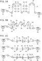
- FIGS. 2A to 2C are schematic views for illustrating the circulating collector 5.
- the collector 5 can be caused to circulate between the roller 51 and the roller 52 by providing the roller 51 and the roller 52 which are drive rollers, and a roller 53 which is a guide roller.
- the roller 53 can be multiply provided; and the movement direction of the collector 5 can be modified arbitrarily by appropriately modifying the arrangement of the multiple rollers 53.
- the collector 5 can be moved in the horizontal direction and the vertical direction.
- the collector 5 can be moved in a direction tilted with respect to the horizontal direction.
- the circulating collector 5 can be multiply provided.
- the multiple collectors 5 can be provided to be arranged in the horizontal direction and can be provided to be arranged in the vertical direction as shown in FIG. 2C .
- the collector 5 may be fed in one direction.
- FIGS. 3A to 3C are schematic views for illustrating the collector 5 fed in one direction.
- the collector 5 can be fed from the roller 51 to the roller 52 by providing the roller 51 and the roller 52 which are drive rollers and the roller 53 which is a guide roller.
- the roller 53 can be multiply provided; and the movement direction of the collector 5 can be modified arbitrarily by appropriately modifying the arrangement of the multiple rollers 53.
- the collector 5 can be moved in the horizontal direction and the vertical direction.
- FIG. 3B the collector 5 can be moved in a direction tilted with respect to the horizontal direction.
- the collector 5 that is fed from the roller 51 to the roller 52 can be multiply provided.
- the multiple collectors 5 can be provided to be arranged in the horizontal direction, and can be provided to be arranged in the vertical direction as shown in FIG. 3C .
- the collector 5 is set to move in the prescribed direction, a continuous deposition operation is possible. Therefore, the production efficiency of the deposited body 110 made of the fiber 100 can be increased.
- the deposited body 110 that is formed on the collector 5 is removed from the collector 5 by a worker.
- the deposited body 110 is used in a nonwoven cloth, a filter, etc.
- the applications of the deposited body 110 are not limited to those illustrated.
- the collector 5 can be omitted.
- the deposited body 110 that is made of the fiber 100 also can be directly formed on the surface of a member that is conductive.
- the member that is conductive it is sufficient for the member that is conductive to be grounded or for a voltage of the reverse polarity of the voltage applied to the nozzle 20 to be applied to the member that is conductive.
- the member that is conductive it is sufficient for the member that is conductive to be moved in the prescribed direction by using a conveyor, an industrial robot, etc.
- the configuration of the member that is conductive is not particularly limited and may be a sheet configuration, may be a block configuration, or may be any configuration.
- the member that is conductive may be fed in one direction, may be moved back and forth, or may be fed to circulate.
- the collector 5 or the member may not move.
- the controller 6 controls the operations of the supplier 32, the source material liquid controller 33, the power supply 4, and the collector 5.
- the controller 6 can be, for example, a computer including a CPU (Central Processing Unit), memory, etc.
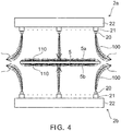
- FIG. 4 is a schematic view for illustrating the repulsion between the fibers 100 at the vicinity of the end portions of the collector 5.
- FIG. 5 is a schematic view for illustrating an electrospinning apparatus 1a according to a second embodiment.
- the second nozzle head 2b opposes the first nozzle head 2a with the collector 5 interposed.
- the second nozzle head 2b is provided at a position overlapping the first nozzle head 2a.
- the second nozzle head 2b is provided at a position that is separated from the first nozzle head 2a in the movement direction 50 of the collector 5.
- the second nozzle head 2b is provided at a position that is shifted in the movement direction 50 of the collector 5 from the position where the first nozzle head 2a is provided.
- the second nozzle head 2b does not overlap the first nozzle head 2a.
- a distance L between the first nozzle head 2a and the second nozzle head 2b can be set to be longer than the longer dimension of the dimension of the deposition region on the first surface 5a of the fiber 100 discharged from the first nozzle head 2a or the dimension of the deposition region on the second surface 5b of the fiber 100 discharged from the second nozzle head 2b.
- the repulsion between the fiber 100 deposited on the first surface 5a and the fiber 100 deposited on the second surface 5b at the vicinity of the end portions of the collector 5 can be suppressed. Therefore, the deposited body 110 can be formed on the entire region of the first surface 5a and the second surface 5b.
- the fluctuation of the thickness and/or the width dimension of the deposited body 110 can be suppressed. Also, the utilization efficiency of the source material liquid can be increased; and the occurrence of the soiling due to the fibers 100 adhering to the interior of the electrospinning apparatus 1a can be suppressed.
- the distance L is the distance between the first nozzle head 2a and the second nozzle head 2b.
- FIGS. 6A to 6C are schematic plan views for illustrating arrangement forms of the first nozzle head 2a and the second nozzle head 2b of the electrospinning apparatus 1a.
- the multiple first nozzle heads 2a can be provided to be arranged in the movement direction 50 of the collector 5.
- the multiple second nozzle heads 2b can be provided to be arranged in the movement direction 50 of the collector 5.
- the multiple first nozzle heads 2a can be arranged at a pitch dimension of 2 L ; and the multiple second nozzle heads 2b can be arranged at a pitch dimension of 2 L .
- the distance between the first nozzle head 2a and the second nozzle head 2b can be set to be L .
- the dimension of the electrospinning apparatus 1a in the movement direction 50 of the collector 5 can be shortened, that is, better space conservation of the electrospinning apparatus 1a can be realized.
- the multiple first nozzle heads 2a can be provided to be arranged in the width direction of the collector 5 as shown in FIG. 6B .
- the multiple second nozzle heads 2b can be provided to be arranged in the width direction of the collector 5.
- the fibers 100 deposited on the first surface 5a may repel each other in the region between the first nozzle heads 2a if the multiple first nozzle heads 2a are provided to be proximal in the width direction of the collector 5.
- the fibers 100 deposited on the second surface 5b may repel each other in the region between the second nozzle heads 2b if the multiple second nozzle heads 2b are provided to be proximal in the width direction of the collector 5.
- one of the first nozzle heads 2a is provided at a position separated from an adjacent other first nozzle head 2a in a direction orthogonal to the movement direction 50 of the collector 5.
- the adjacent other first nozzle head 2a is provided at a position shifted in the direction orthogonal to the movement direction 50 of the collector 5.
- One of the second nozzle heads 2b is provided at a position separated from an adjacent second nozzle head 2b in the direction orthogonal to the movement direction 50 of the collector 5.
- the adjacent second nozzle head 2b is provided at a position shifted in the direction orthogonal to the movement direction 50 of the collector 5.
- the multiple first nozzle heads 2a can be provided to be arranged in a staggered configuration in the movement direction 50 of the collector 5.
- the multiple second nozzle heads 2b can be provided to be arranged in a staggered configuration in the movement direction 50 of the collector 5.
- the multiple second nozzle heads 2b can be provided to not overlap the multiple first nozzle heads 2a when viewed in plan.
- the direction in which the first nozzle head 2a extends can be set to be parallel to the movement direction 50 of the collector 5.
- the multiple first nozzle heads 2a can be provided to be arranged in the width direction of the collector 5.
- one of the first nozzle heads 2a is provided at a position separated from an adjacent other first nozzle head 2a in a direction orthogonal to the movement direction 50 of the collector 5.
- the adjacent other first nozzle head 2a is provided at a position shifted in the direction orthogonal to the movement direction 50 of the collector 5.
- the direction in which the second nozzle head 2b extends can be set to be parallel to the movement direction 50 of the collector 5.
- the multiple second nozzle heads 2b can be provided to be arranged in the width direction of the collector 5.
- one of the second nozzle heads 2b is provided at a position separated from an adjacent second nozzle head 2b in the direction orthogonal to the movement direction 50 of the collector 5.
- the adjacent second nozzle head 2b is provided at a position shifted in the direction orthogonal to the movement direction 50 of the collector 5.
- FIG. 7 is a schematic plan view for illustrating a first nozzle head 2a1 and a second nozzle head 2b1 according to another embodiment.
- an angle ⁇ a between the direction in which the first nozzle head 2a1 extends and the movement direction 50 of the collector 5 can be changed.
- the angle ⁇ a between the direction in which the first nozzle head 2a extends and the movement direction 50 of the collector 5 is changeable for the first nozzle head 2a.
- An angle ⁇ b between the direction in which the second nozzle head 2b1 extends and the movement direction 50 of the collector 5 can be changed.
- the angle ⁇ b between the direction in which the second nozzle head 2b extends and the movement direction 50 of the collector 5 is changeable for the second nozzle head 2b.
- the deposited bodies 110 that have different width dimensions in the first surface 5a can be formed easily.
- the deposited bodies 110 that have different width dimensions in the second surface 5b can be formed easily.
- collectors 5 that have different width dimensions W can be accommodated easily.
- the source material liquid collects at the vicinity of the outlet 20a of the nozzle 20 due to surface tension.
- the power supply 4 applies the voltage to the nozzle 20. Then, the source material liquid that is at the vicinity of the outlet 20a is charged with a prescribed polarity. In the case of the electrospinning apparatuses 1 and 1a illustrated in FIG. 1 and FIG. 5 , the source material liquid that is at the vicinity of the outlet 20a is charged to be positive.
- the electrospinning apparatus 1a the repulsion between the fiber 100 deposited on the first surface 5a and the fiber 100 deposited on the second surface 5b at the vicinity of the end portions of the collector 5 can be suppressed. Therefore, the deposited body 110 can be formed on the entire region of the first surface 5a and the second surface 5b. Also, the fluctuation of the thickness and/or the width dimension of the deposited body 110 can be suppressed. Also, the utilization efficiency of the source material liquid can be increased; and the occurrence of soiling due to the fiber 100 adhering to the interior of the electrospinning apparatus 1a can be suppressed.
Landscapes
- Engineering & Computer Science (AREA)
- Textile Engineering (AREA)
- Mechanical Engineering (AREA)
- Spinning Methods And Devices For Manufacturing Artificial Fibers (AREA)
- Nonwoven Fabrics (AREA)
Abstract
Description
- An embodiment of the invention relates to an electrospinning apparatus.
- There is an electrospinning apparatus that deposits a fine fiber on the surface of a member by electrospinning (also called electric field spinning, charge-induced spinning, etc.).
- A nozzle head that includes multiple nozzles discharging a source material liquid is provided in the electrospinning apparatus. Also, an electrospinning apparatus including a nozzle head and a member having a band configuration has been proposed. The member and the nozzle head are provided to oppose each other. In the electrospinning apparatus that includes the member having the band configuration, the fiber is deposited on the surface of the member having the band configuration while moving the member having the band configuration. Thus, a deposited body that includes the fiber can be produced continuously; therefore, the productivity of the deposited body can be increased.
- In such a case, the production amount of the deposited body per unit time or per unit surface area can be increased by increasing the number of nozzle heads. However, if the number of nozzle heads is simply increased, this may cause an enlargement of the electrospinning apparatus.
- Therefore, it has been desirable to develop an electrospinning apparatus in which improvement of the productivity and better space conservation can be realized.
- [PTL 1]
JP-A 2007-92213 - A problem to be solved by the invention is to provide an electrospinning apparatus in which improvement of the productivity and better space conservation can be realized.
- An electrospinning apparatus according to an embodiment is configured to deposit a fiber on a collector or a member. The electrospinning apparatus includes a first nozzle head provided on one side of the collector or the member, and a second nozzle head provided on the side opposite to the first nozzle head with the collector or the member interposed.
-
-
FIG. 1 is a schematic view for illustrating an electrospinning apparatus according to a first embodiment. -
FIGS. 2A to 2C are schematic views for illustrating circulating collectors. -
FIGS. 3A to 3C are schematic views for illustrating collectors fed in one direction. -
FIG. 4 is a schematic view for illustrating the repulsion between fibers at the vicinity of end portions of the collector. -
FIG. 5 is a schematic view for illustrating an electrospinning apparatus according to a second embodiment. -
FIGS. 6A to 6C are schematic plan views for illustrating arrangement forms of a first nozzle head and a second nozzle head of the electrospinning apparatus. -
FIG. 7 is a schematic plan view for illustrating the first nozzle head and the second nozzle head according to another embodiment. - Embodiments will now be illustrated with reference to the drawings. Similar components in the drawings are marked with the same reference numerals; and a detailed description is omitted as appropriate.
- An
electrospinning apparatus 1 that includes a so-called needle-type nozzle head will now be illustrated as an example. However, the configuration of the nozzle provided in the nozzle head is not limited to a needle-like configuration. - For example, the nozzle that is provided in the nozzle head may be a nozzle having a circular conic configuration, etc. In such a case, if a nozzle having a needle-like configuration is used, electric field concentration occurs easily at the vicinity of the outlet of the nozzle; therefore, the strength of the electric field generated between the nozzle and the collector becomes high. On the other hand, if a nozzle having a circular conic configuration is used, the mechanical strength of the nozzle can be increased. Also, because the tip of the nozzle having the circular conic configuration can be sharp, the strength of the electric field generated between the nozzle and the collector becomes high similarly to the nozzle having the needle-like configuration.
- Further, the nozzle head may be a so-called blade-type nozzle head, etc. If a blade-type nozzle head is used, the mechanical strength can be increased; therefore, damage of the nozzle head when cleaning, etc., can be suppressed. Also, the cleaning of the nozzle head is easy. The configuration of the blade-type nozzle head is not particularly limited and may be, for example, a rectangular parallelepiped configuration or a circular arc-like configuration.
-
FIG. 1 is a schematic view for illustrating theelectrospinning apparatus 1 according to a first embodiment. - As shown in
FIG. 1 , afirst nozzle head 2a, asecond nozzle head 2b, a source materialliquid supplier 3, apower supply 4, acollector 5, and a controller 6 are provided in theelectrospinning apparatus 1. - The
first nozzle head 2a is provided on one side of thecollector 5. For example, thefirst nozzle head 2a is provided above thecollector 5. Thefirst nozzle head 2a opposes afirst surface 5a of thecollector 5. - The
second nozzle head 2b is provided on the side opposite to thefirst nozzle head 2a with thecollector 5 interposed. For example, thesecond nozzle head 2b is provided below thecollector 5. Thesecond nozzle head 2b opposes asecond surface 5b of thecollector 5 on the side opposite to thefirst surface 5a. - In the case of the components illustrated in
FIG. 1 , thesecond nozzle head 2b opposes thefirst nozzle head 2a with thecollector 5 interposed. In other words, when viewed in plan, thesecond nozzle head 2b is provided at a position overlapping thefirst nozzle head 2a. - The
first nozzle head 2a and thesecond nozzle head 2b includenozzles 20,connectors 21, andmain parts 22. - The
nozzle 20 has a needle-like configuration. A hole for discharging the source material liquid is provided in the interior of thenozzle 20. The hole for discharging the source material liquid communicates between the end portion of thenozzle 20 on theconnector 21 side and the end portion (the tip) of thenozzle 20 on thecollector 5 side. The opening of the hole for discharging the source material liquid on thecollector 5 side is anoutlet 20a. - Although the outer diameter dimension (in the case where the
nozzle 20 has a cylindrical configuration, the diametrical dimension) of thenozzle 20 is not particularly limited, it is favorable for the outer diameter dimension to be small. If the outer diameter dimension is set to be small, electric field concentration occurs easily at the vicinity of theoutlet 20a of thenozzle 20. If the electric field concentration occurs at the vicinity of theoutlet 20a of thenozzle 20, the strength of the electric field generated between thenozzle 20 and thecollector 5 can be increased compared to the case where the outer diameter dimension of thenozzle 20 is large. Therefore, the voltage that is applied by thepower supply 5 can be set to be low compared to the case where the outer diameter dimension of thenozzle 20 is large. In other words, the drive voltage can be reduced compared to the case where the outer diameter dimension of thenozzle 20 is large. In such a case, for example, the outer diameter dimension of thenozzle 20 can be set to about 0.3 mm to 1.3 mm. - The dimension (in the case where the
outlet 20a is a circle, the diametrical dimension) of theoutlet 20a is not particularly limited. The dimension of theoutlet 20a can be modified appropriately according to the cross-sectional dimension of afiber 100 to be formed. For example, the dimension of theoutlet 20a (the inner diameter dimension of the nozzle 20) can be set to about 0.1 mm to 1 mm. - The
nozzle 20 is formed from a conductive material. It is favorable for the material of thenozzle 20 to be conductive and to have resistance to the source material liquid described below. For example, thenozzle 20 can be formed from stainless steel, etc. - The number of the
nozzles 20 is not particularly limited and can be modified appropriately according to the size of thecollector 5, etc. It is sufficient for at least onenozzle 20 to be provided. - In the case where
multiple nozzles 20 are provided, themultiple nozzles 20 are provided to be arranged at a prescribed spacing. For example, themultiple nozzles 20 can be provided to be arranged in a direction orthogonal to amovement direction 50 of thecollector 5. Also, the arrangement form of themultiple nozzles 20 is not particularly limited. For example, themultiple nozzles 20 also can be provided to be arranged in one column, can be provided to be arranged in multiple columns, can be provided to be arranged on a circumference or on concentric circles, or can be provided to be arranged in a staggered configuration or a matrix configuration. - The
connector 21 is provided between thenozzle 20 and themain part 22. A hole for supplying the source material liquid from themain part 22 to thenozzle 20 is provided in the interior of theconnector 21. The hole that is provided in the interior of theconnector 21 communicates with the hole provided in the interior of thenozzle 20 and the space provided in the interior of themain part 22. - The
connector 21 is formed from a conductive material. It is favorable for the material of theconnector 21 to be conductive and to have resistance to the source material liquid. For example, theconnector 21 can be formed from stainless steel, etc. - In the case where the voltage is directly applied to the
nozzle 20, it is not always necessary for theconnector 21 to be formed from a conductive material. - The
connector 21 is not always necessary; and thenozzle 20 may be provided directly at themain part 22. - However, there are cases where the source material liquid that is discharged adheres to the end portion of the
nozzle 20 on theoutlet 20a side and to the vicinity of the end portion. Therefore, it is favorable to perform, as necessary or regularly, cleaning of the end portion of thenozzle 20 on theoutlet 20a side and the vicinity of the end portion. - In such a case, the end portion of the
nozzle 20 on theconnector 21 side can be fixed to theconnector 21; and theconnector 21 can be provided detachably at themain part 22. For example, an external-thread screw can be provided in the end portion of theconnector 21 on themain part 22 side; and an internal-thread tap can be provided in the side surface of themain part 22. Also, theconnector 21 can be provided detachably at themain part 22 by using a luer taper (luer taper) (also called a luer adapter, a luer lock, a luer connector, a luer fit, etc.). For example, a female luer (female luer) can be provided on themain part 22 side of theconnector 21; and a male luer (male luer) can be provided on the side surface of themain part 22. In other words, theconnector 21 may be connected to themain part 22 by using a screw or a luer taper. - A space in which the source material liquid is stored is provided in the interior of the
main part 22. Although the configuration of themain part 22 is not particularly limited, themain part 22 can have a rod configuration in the case where themultiple nozzles 20 are provided. For example, themain part 22 that has the rod configuration can extend in a direction orthogonal to themovement direction 50 of thecollector 5. Themain part 22 that has the rod configuration can be provided to be parallel to thefirst surface 5a or thesecond surface 5b of thecollector 5. - Also, a
supply port 22a is provided in themain part 22. The source material liquid that is supplied from the sourcematerial liquid supplier 3 is introduced to the interior of themain part 22 via thesupply port 22a. The number and the arrangement positions of thesupply ports 22a are not particularly limited. For example, thesupply port 22a can be provided on the side opposite to the side where thenozzle 20 of themain part 22 is provided. - It is favorable for the material of the
main part 22 to be conductive and to have resistance to the source material liquid. For example, themain part 22 can be formed from stainless steel, etc. - The source
material liquid supplier 3 includes acontainer 31, asupplier 32, a source materialliquid controller 33, and apipe 34. - The
container 31 stores the source material liquid. Thecontainer 31 is formed from a material having resistance to the source material liquid. For example, thecontainer 31 can be formed from stainless steel, etc. - The source material liquid is a polymeric substance dissolved in a solvent.
- The polymeric substance is not particularly limited and can be modified appropriately according to the material properties of the
fiber 100 to be formed. The polymeric substance can be, for example, polypropylene, polyethylene, polystyrene, polyethylene terephthalate, polyvinyl chloride, polycarbonate, nylon, aramid, etc. - It is sufficient for the solvent to be able to dissolve the polymeric substance. The solvent can be modified appropriately according to the polymeric substance to be dissolved. The solvent can be, for example, methanol, ethanol, isopropyl alcohol, acetone, benzene, toluene, etc.
- The polymeric substance and the solvent are not limited to those illustrated.
- Also, the source material liquid can be produced from a solvent and one type of polymeric substance, or can be produced by mixing a solvent and multiple types of polymeric substances.
- Also, the source material liquid that is supplied to the
first nozzle head 2a and the source material liquid that is supplied to thesecond nozzle head 2b may be of the same type; or the source material liquid that is supplied to thefirst nozzle head 2a and the source material liquid that is supplied to thesecond nozzle head 2b may be of different types. - The source material liquid is caused to collect at the vicinity of the
outlet 20a by surface tension. To this end, the viscosity of the source material liquid can be modified appropriately according to the dimension of theoutlet 20a, etc. The viscosity of the source material liquid can be determined by performing experiments and/or simulations. Also, the viscosity of the source material liquid can be controlled by the mixture proportion of the solvent and the polymeric substance. - The
supplier 32 supplies the source material liquid stored in thecontainer 31 to themain part 22. Thesupplier 32 can be, for example, a pump having resistance to the source material liquid, etc. Also, for example, thesupplier 32 may feed the source material liquid stored in thecontainer 31 by supplying a gas to thecontainer 31. - The source material
liquid controller 33 controls the flow rate, the pressure, etc., of the source material liquid supplied to themain part 22 so that the source material liquid in the interior of themain part 22 is not pushed out from theoutlet 20a when new source material liquid is supplied to the interior of themain part 22. In other words, the source material liquid is caused to collect at the vicinity of theoutlet 20a by the surface tension. The control amount for the source materialliquid controller 33 can be modified appropriately by the dimension of theoutlet 20a, the viscosity of the source material liquid, etc. The control amount for the source materialliquid controller 33 can be determined by performing experiments and/or simulations. - Also, the source material
liquid controller 33 can be able to switch between the starting of the supply and the stopping of the supply of the source material liquid. - The
supplier 32 and the source materialliquid controller 33 are not always necessary. For example, if thecontainer 31 is provided at a position that is higher than the position of themain part 22, the source material liquid can be supplied to themain part 22 by utilizing gravity. Then, the source material liquid that is in the interior of themain part 22 can be caused not to be pushed out from theoutlet 20a when the new source material liquid is supplied to the interior of themain part 22 by appropriately setting the height position of thecontainer 31. In such a case, the height position of thecontainer 31 can be modified appropriately using the dimension of theoutlet 20a, the viscosity of the source material liquid, etc. The height position of thecontainer 31 can be determined by performing experiments and/or simulations. - The
pipe 34 is provided between thecontainer 31 and thesupplier 32, between thesupplier 32 and the source materialliquid controller 33, and between the source materialliquid controller 33 and themain part 22. Thepipe 34 is used as a flow channel of the source material liquid. Thepipe 34 is formed from a material having resistance to the source material liquid. - The
power supply 4 applies the voltage to thenozzle 20 via themain part 22 and theconnector 21. Not-illustrated terminals that are electrically connected to thenozzle 20 may be provided. In such a case, thepower supply 4 applies the voltage to thenozzle 20 via the not-illustrated terminals. In other words, it is sufficient for the voltage to be able to be applied to thenozzle 20 from thepower supply 4. - The polarity of the voltage (the drive voltage) applied to the
nozzle 20 can be set to be positive or set to be negative. However, if a negative voltage is applied to thenozzle 20, irregular electric discharge occurs easily because electrons are discharged from the tip of thenozzle 20. Therefore, as shown inFIG. 1 , it is favorable for the polarity of the voltage applied to thenozzle 20 to be positive. - The voltage that is applied to the
nozzle 20 can be modified appropriately according to the type of the polymeric substance included in the source material liquid, the distance between thenozzle 20 and thecollector 5, etc. For example, thepower supply 4 can apply a voltage to thenozzle 20 so that the potential difference between thenozzle 20 and thecollector 5 is 10 kV or more. In such a case, if a blade-type nozzle head is used, the voltage that is applied to the nozzle is about 70 kV. On the other hand, if a needle-type nozzle head such as that illustrated inFIG. 1 is used, the voltage that is applied to thenozzle 20 can be set to 50 kV or less. Therefore, a reduction of the drive voltage can be realized. - The
power supply 4 can be, for example, a direct current-high voltage power supply. For example, thepower supply 4 can output a direct current voltage of not less than 10 kV and not more than 100 kV. - The
electrospinning apparatus 1 illustrated inFIG. 1 supplies the source material liquid to thefirst nozzle head 2a and thesecond nozzle head 2b by one sourcematerial liquid supplier 3 and applies the voltage to thefirst nozzle head 2a and thesecond nozzle head 2b by onepower supply 4. Thus, simplification of the configuration, better space conservation, a reduction of the manufacturing cost, etc., of theelectrospinning apparatus 1 can be realized. - On the other hand, one each of the source
material liquid supplier 3 and thepower supply 4 can be provided respectively for thefirst nozzle head 2a and thesecond nozzle head 2b. Thus, the control of the supply amount of the source material liquid and/or the control of the applied voltage can be performed respectively for thefirst nozzle head 2a and thesecond nozzle head 2b. Therefore, the deposition amount of thefiber 100 at thefirst surface 5a of thecollector 5 and the deposition amount of thefiber 100 at thesecond surface 5b of thecollector 5 can be changed. For example, it is possible to simultaneously form depositedbodies 110 having different thicknesses. - The
collector 5 is provided on the side of thenozzle 20 where the source material liquid is discharged. Thecollector 5 is grounded. A voltage of the reverse polarity of the voltage applied to thenozzle 20 may be applied to thecollector 5. Thecollector 5 can be formed from a conductive material. It is favorable for the material of thecollector 5 to be conductive and to have resistance to the source material liquid. The material of thecollector 5 can be, for example, stainless steel, etc. - The
collector 5 moves in a prescribed direction. Thecollector 5 illustrated inFIG. 1 has a band configuration. For example, one end portion of thecollector 5 can be provided at a not-illustrated first roller; and another end portion of thecollector 5 can be provided at a not-illustrated second roller. Then, drive mechanisms such as motors, etc., can be connected to the first roller and the second roller; and thecollector 5 can be caused to move back and forth between the first roller and the second roller. - Also, the
collector 5 may be, for example, a plate-like body moved in the prescribed direction by an industrial robot, etc. - Also, the
collector 5 may be, for example, a drum rotating in the prescribed direction. - Also, the
collector 5 may be caused to circulate between aroller 51 and aroller 52 as a belt of a belt conveyor. -
FIGS. 2A to 2C are schematic views for illustrating the circulatingcollector 5. - As shown in
FIGS. 2A to 2C , thecollector 5 can be caused to circulate between theroller 51 and theroller 52 by providing theroller 51 and theroller 52 which are drive rollers, and aroller 53 which is a guide roller. In such a case, theroller 53 can be multiply provided; and the movement direction of thecollector 5 can be modified arbitrarily by appropriately modifying the arrangement of themultiple rollers 53. For example, as shown inFIG. 2A , thecollector 5 can be moved in the horizontal direction and the vertical direction. As shown inFIG. 2B , thecollector 5 can be moved in a direction tilted with respect to the horizontal direction. - Also, the circulating
collector 5 can be multiply provided. In such a case, themultiple collectors 5 can be provided to be arranged in the horizontal direction and can be provided to be arranged in the vertical direction as shown inFIG. 2C . - Also, the
collector 5 may be fed in one direction. -
FIGS. 3A to 3C are schematic views for illustrating thecollector 5 fed in one direction. As shown inFIGS. 3A to 3C , thecollector 5 can be fed from theroller 51 to theroller 52 by providing theroller 51 and theroller 52 which are drive rollers and theroller 53 which is a guide roller. In such a case, theroller 53 can be multiply provided; and the movement direction of thecollector 5 can be modified arbitrarily by appropriately modifying the arrangement of themultiple rollers 53. For example, as shown inFIG. 3A , thecollector 5 can be moved in the horizontal direction and the vertical direction. As shown inFIG. 3B , thecollector 5 can be moved in a direction tilted with respect to the horizontal direction. - Also, the
collector 5 that is fed from theroller 51 to theroller 52 can be multiply provided. In such a case, themultiple collectors 5 can be provided to be arranged in the horizontal direction, and can be provided to be arranged in the vertical direction as shown inFIG. 3C . - If the
collector 5 is set to move in the prescribed direction, a continuous deposition operation is possible. Therefore, the production efficiency of the depositedbody 110 made of thefiber 100 can be increased. - The deposited
body 110 that is formed on thecollector 5 is removed from thecollector 5 by a worker. For example, the depositedbody 110 is used in a nonwoven cloth, a filter, etc. The applications of the depositedbody 110 are not limited to those illustrated. - Also, the
collector 5 can be omitted. For example, the depositedbody 110 that is made of thefiber 100 also can be directly formed on the surface of a member that is conductive. In such a case, it is sufficient for the member that is conductive to be grounded or for a voltage of the reverse polarity of the voltage applied to thenozzle 20 to be applied to the member that is conductive. Also, it is sufficient for the member that is conductive to be moved in the prescribed direction by using a conveyor, an industrial robot, etc. For example, the configuration of the member that is conductive is not particularly limited and may be a sheet configuration, may be a block configuration, or may be any configuration. - The member that is conductive may be fed in one direction, may be moved back and forth, or may be fed to circulate.
- Also, the
collector 5 or the member may not move. - The controller 6 controls the operations of the
supplier 32, the source materialliquid controller 33, thepower supply 4, and thecollector 5. The controller 6 can be, for example, a computer including a CPU (Central Processing Unit), memory, etc. - Here, in the case where the
fibers 100 that are charged with the same polarity are deposited on thefirst surface 5a and thesecond surface 5b of thecollector 5, there are cases where thefiber 100 deposited on thefirst surface 5a and thefiber 100 deposited on thesecond surface 5b repel each other at the vicinity of the end portion of thecollector 5. -
FIG. 4 is a schematic view for illustrating the repulsion between thefibers 100 at the vicinity of the end portions of thecollector 5. - As shown in
FIG. 4 , in the case where the repulsion between thefibers 100 occurs at the vicinity of the end portions of thecollector 5, it becomes difficult to deposit thefibers 100 at the vicinity of the end portions of thecollector 5. Therefore, there is a risk that the thickness at the vicinity of the end portion of the depositedbody 110 may become thin; and the width dimension of the depositedbody 110 may fluctuate. Also, there is a risk that the utilization efficiency of the source material liquid may decrease; and soiling may occur due to thefibers 100 adhered to the interior of theelectrospinning apparatus 1. -
FIG. 5 is a schematic view for illustrating anelectrospinning apparatus 1a according to a second embodiment. - In the
electrospinning apparatus 1 described above, thesecond nozzle head 2b opposes thefirst nozzle head 2a with thecollector 5 interposed. In other words, when viewed in plan, thesecond nozzle head 2b is provided at a position overlapping thefirst nozzle head 2a. - Conversely, in the
electrospinning apparatus 1a according to the embodiment, thesecond nozzle head 2b is provided at a position that is separated from thefirst nozzle head 2a in themovement direction 50 of thecollector 5. For example, thesecond nozzle head 2b is provided at a position that is shifted in themovement direction 50 of thecollector 5 from the position where thefirst nozzle head 2a is provided. In other words, when viewed in plan, thesecond nozzle head 2b does not overlap thefirst nozzle head 2a. In such a case, a distance L between thefirst nozzle head 2a and thesecond nozzle head 2b can be set to be longer than the longer dimension of the dimension of the deposition region on thefirst surface 5a of thefiber 100 discharged from thefirst nozzle head 2a or the dimension of the deposition region on thesecond surface 5b of thefiber 100 discharged from thesecond nozzle head 2b. Thus, the repulsion between thefiber 100 deposited on thefirst surface 5a and thefiber 100 deposited on thesecond surface 5b at the vicinity of the end portions of thecollector 5 can be suppressed. Therefore, the depositedbody 110 can be formed on the entire region of thefirst surface 5a and thesecond surface 5b. Also, the fluctuation of the thickness and/or the width dimension of the depositedbody 110 can be suppressed. Also, the utilization efficiency of the source material liquid can be increased; and the occurrence of the soiling due to thefibers 100 adhering to the interior of theelectrospinning apparatus 1a can be suppressed. - When viewed in plan, the distance L is the distance between the
first nozzle head 2a and thesecond nozzle head 2b. -
FIGS. 6A to 6C are schematic plan views for illustrating arrangement forms of thefirst nozzle head 2a and thesecond nozzle head 2b of theelectrospinning apparatus 1a. - As shown in
FIG. 6A , the multiple first nozzle heads 2a can be provided to be arranged in themovement direction 50 of thecollector 5. The multiple second nozzle heads 2b can be provided to be arranged in themovement direction 50 of thecollector 5. In such a case, the multiple first nozzle heads 2a can be arranged at a pitch dimension of 2L; and the multiple second nozzle heads 2b can be arranged at a pitch dimension of 2L. Then, when viewed in plan, the distance between thefirst nozzle head 2a and thesecond nozzle head 2b can be set to be L. Thus, the dimension of theelectrospinning apparatus 1a in themovement direction 50 of thecollector 5 can be shortened, that is, better space conservation of theelectrospinning apparatus 1a can be realized. - Also, in the case where a width dimension W (a dimension in a direction orthogonal to the movement direction 50) of the
collector 5 is long, the multiple first nozzle heads 2a can be provided to be arranged in the width direction of thecollector 5 as shown inFIG. 6B . The multiple second nozzle heads 2b can be provided to be arranged in the width direction of thecollector 5. - In such a case, there is a risk that the
fibers 100 deposited on thefirst surface 5a may repel each other in the region between the first nozzle heads 2a if the multiple first nozzle heads 2a are provided to be proximal in the width direction of thecollector 5. There is a risk that thefibers 100 deposited on thesecond surface 5b may repel each other in the region between the second nozzle heads 2b if the multiple second nozzle heads 2b are provided to be proximal in the width direction of thecollector 5. - Therefore, one of the
first nozzle heads 2a is provided at a position separated from an adjacent otherfirst nozzle head 2a in a direction orthogonal to themovement direction 50 of thecollector 5. In other words, the adjacent otherfirst nozzle head 2a is provided at a position shifted in the direction orthogonal to themovement direction 50 of thecollector 5. One of thesecond nozzle heads 2b is provided at a position separated from an adjacentsecond nozzle head 2b in the direction orthogonal to themovement direction 50 of thecollector 5. In other words, the adjacentsecond nozzle head 2b is provided at a position shifted in the direction orthogonal to themovement direction 50 of thecollector 5. - For example, as shown in
FIG. 6B , the multiple first nozzle heads 2a can be provided to be arranged in a staggered configuration in themovement direction 50 of thecollector 5. The multiple second nozzle heads 2b can be provided to be arranged in a staggered configuration in themovement direction 50 of thecollector 5. - Also, to suppress the repulsion between the
fiber 100 deposited on thefirst surface 5a and thefiber 100 deposited on thesecond surface 5b at the vicinity of the end portions of thecollector 5, the multiple second nozzle heads 2b can be provided to not overlap the multiple first nozzle heads 2a when viewed in plan. - Also, in the case where the width dimension W of the
collector 5 is short as shown inFIG. 6C , the direction in which thefirst nozzle head 2a extends can be set to be parallel to themovement direction 50 of thecollector 5. Also, the multiple first nozzle heads 2a can be provided to be arranged in the width direction of thecollector 5. Also, to suppress thefibers 100 deposited on thefirst surface 5a repelling each other in the region between the first nozzle heads 2a, one of thefirst nozzle heads 2a is provided at a position separated from an adjacent otherfirst nozzle head 2a in a direction orthogonal to themovement direction 50 of thecollector 5. In other words, the adjacent otherfirst nozzle head 2a is provided at a position shifted in the direction orthogonal to themovement direction 50 of thecollector 5. - The direction in which the
second nozzle head 2b extends can be set to be parallel to themovement direction 50 of thecollector 5. Also, the multiple second nozzle heads 2b can be provided to be arranged in the width direction of thecollector 5. Also, to suppress thefibers 100 deposited on thesecond surface 5b repelling each other in the region between the second nozzle heads 2b, one of thesecond nozzle heads 2b is provided at a position separated from an adjacentsecond nozzle head 2b in the direction orthogonal to themovement direction 50 of thecollector 5. In other words, the adjacentsecond nozzle head 2b is provided at a position shifted in the direction orthogonal to themovement direction 50 of thecollector 5. -
FIG. 7 is a schematic plan view for illustrating a first nozzle head 2a1 and a second nozzle head 2b1 according to another embodiment. - As shown in
FIG. 7 , an angle θa between the direction in which the first nozzle head 2a1 extends and themovement direction 50 of thecollector 5 can be changed. In other words, the angle θa between the direction in which thefirst nozzle head 2a extends and themovement direction 50 of thecollector 5 is changeable for thefirst nozzle head 2a. - An angle θb between the direction in which the second nozzle head 2b1 extends and the
movement direction 50 of thecollector 5 can be changed. In other words, the angle θb between the direction in which thesecond nozzle head 2b extends and themovement direction 50 of thecollector 5 is changeable for thesecond nozzle head 2b. - For example, it is sufficient to provide one end portion of a shaft perpendicular to the
first surface 5a of thecollector 5 at themain part 22 of thefirst nozzle head 2a and to provide a holder that rotatably holds the shaft. It is sufficient to provide one end portion of a shaft perpendicular to thesecond surface 5b of thecollector 5 at themain part 22 of thesecond nozzle head 2b and to provide a holder that rotatably holds the shaft. - Thus, by appropriately modifying the angle θa, the deposited
bodies 110 that have different width dimensions in thefirst surface 5a can be formed easily. By appropriately modifying the angle θb, the depositedbodies 110 that have different width dimensions in thesecond surface 5b can be formed easily. - Also,
collectors 5 that have different width dimensions W can be accommodated easily. - Effects of the
electrospinning apparatuses - The source material liquid collects at the vicinity of the
outlet 20a of thenozzle 20 due to surface tension. - The
power supply 4 applies the voltage to thenozzle 20. Then, the source material liquid that is at the vicinity of theoutlet 20a is charged with a prescribed polarity. In the case of theelectrospinning apparatuses FIG. 1 andFIG. 5 , the source material liquid that is at the vicinity of theoutlet 20a is charged to be positive. - An electric field is generated between the
nozzle 20 and thecollector 5 because thecollector 5 is grounded. Then, when the electrostatic force acting along the lines of electric force becomes larger than the surface tension, the source material liquid that is at the vicinity of theoutlet 20a is drawn out toward thecollector 5 by the electrostatic force. The source material liquid that is drawn out is elongated; and thefiber 100 is formed by the volatilization of the solvent included in the source material liquid. Thefiber 100 that is formed is deposited on thefirst surface 5a and thesecond surface 5b of thecollector 5 to form the depositedbody 110 on thefirst surface 5a and thesecond surface 5b. - Also, in the case of the
electrospinning apparatus 1a, the repulsion between thefiber 100 deposited on thefirst surface 5a and thefiber 100 deposited on thesecond surface 5b at the vicinity of the end portions of thecollector 5 can be suppressed. Therefore, the depositedbody 110 can be formed on the entire region of thefirst surface 5a and thesecond surface 5b. Also, the fluctuation of the thickness and/or the width dimension of the depositedbody 110 can be suppressed. Also, the utilization efficiency of the source material liquid can be increased; and the occurrence of soiling due to thefiber 100 adhering to the interior of theelectrospinning apparatus 1a can be suppressed. - While certain embodiments have been described, these embodiments have been presented by way of example only, and are not intended to limit the scope of the inventions. Indeed, the novel embodiments described herein may be embodied in a variety of other forms; furthermore, various omissions, substitutions and changes in the form of the embodiments described herein may be made without departing from the spirit of the inventions. The accompanying claims and their equivalents are intended to cover such forms or modifications as would fall within the scope and spirit of the invention. Moreover, above-mentioned embodiments can be combined mutually and can be carried out.
Claims (10)
- An electrospinning apparatus configured to deposit a fiber on a collector or a member, the electrospinning apparatus comprising:a first nozzle head provided on one side of the collector or the member; anda second nozzle head provided on a side opposite to the first nozzle head with the collector or the member interposed.
- The electrospinning apparatus according to claim 1, wherein the second nozzle head opposes the first nozzle head with the collector or the member interposed.
- The electrospinning apparatus according to claim 1, wherein the second nozzle head is provided at a position separated from the first nozzle head in a movement direction of the collector or the member.
- The electrospinning apparatus according to any one of claims 1 to 3, wherein a plurality of the first nozzle heads is provided to be arranged in a movement direction of the collector or the member.
- The electrospinning apparatus according to claim 4, wherein one of the first nozzle heads is provided at a position separated from an adjacent other of the first nozzle heads in a direction orthogonal to the movement direction of the collector or the member.
- The electrospinning apparatus according to claim 4 or 5, wherein one of the first nozzle heads is provided on one end portion side of the collector or the member in a direction orthogonal to the movement direction of the collector or the member, and an adjacent other of the first nozzle heads is provided on another end portion side of the collector or the member in the direction.
- The electrospinning apparatus according to any one of claims 1 to 6, wherein a plurality of the second nozzle heads is provided to be arranged in a movement direction of the collector or the member.
- The electrospinning apparatus according to claim 7, wherein one of the second nozzle heads is provided at a position separated from an adjacent other of the second nozzle heads in a direction orthogonal to the movement direction of the collector or the member.
- The electrospinning apparatus according to claim 7 or 8, wherein one of the second nozzle heads is provided on one end portion side of the collector or the member in a direction orthogonal to the movement direction of the collector or the member, and an adjacent other of the second nozzle heads is provided on another end portion side of the collector or the member in the direction.
- The electrospinning apparatus according to any one of claims 1 to 9, wherein an angle is changeable for at least one of the first nozzle head or the second nozzle head, the angle being between an extension direction of the nozzle head and a movement direction of the collector or the member.
Applications Claiming Priority (2)
| Application Number | Priority Date | Filing Date | Title |
|---|---|---|---|
| JP2016221299A JP6612715B2 (en) | 2016-11-14 | 2016-11-14 | Electrospinning device |
| PCT/JP2017/032478 WO2018088014A1 (en) | 2016-11-14 | 2017-09-08 | Electrospinning apparatus |
Publications (2)
| Publication Number | Publication Date |
|---|---|
| EP3550059A1 true EP3550059A1 (en) | 2019-10-09 |
| EP3550059A4 EP3550059A4 (en) | 2020-08-26 |
Family
ID=62109646
Family Applications (1)
| Application Number | Title | Priority Date | Filing Date |
|---|---|---|---|
| EP17847719.6A Pending EP3550059A4 (en) | 2016-11-14 | 2017-09-08 | ELECTRIC SPINNING DEVICE |
Country Status (6)
| Country | Link |
|---|---|
| US (1) | US10920341B2 (en) |
| EP (1) | EP3550059A4 (en) |
| JP (1) | JP6612715B2 (en) |
| KR (1) | KR102070396B1 (en) |
| CN (1) | CN108323174B (en) |
| WO (1) | WO2018088014A1 (en) |
Families Citing this family (8)
| Publication number | Priority date | Publication date | Assignee | Title |
|---|---|---|---|---|
| WO2018195409A1 (en) | 2017-04-20 | 2018-10-25 | Case Western Reserve University | Electrochemically produced materials; devices and methods for production |
| JP7242353B2 (en) * | 2019-03-12 | 2023-03-20 | 株式会社東芝 | Electrospinning head and electrospinning device |
| CN110257928B (en) * | 2019-05-31 | 2021-06-18 | 中鸿纳米纤维技术丹阳有限公司 | Special solution supply equipment for nanofiber electrostatic spinning |
| JP7344040B2 (en) | 2019-08-08 | 2023-09-13 | 株式会社東芝 | Electrospinning device and method for manufacturing separator-integrated electrode |
| JP7374672B2 (en) * | 2019-09-05 | 2023-11-07 | 株式会社東芝 | Electrospinning head and electrospinning device |
| JP7588966B2 (en) * | 2020-05-21 | 2024-11-25 | 株式会社東芝 | Fiber sheet manufacturing method and fiber sheet manufacturing device |
| JP7689302B2 (en) * | 2021-05-19 | 2025-06-06 | パナソニックIpマネジメント株式会社 | Fiber assembly manufacturing apparatus and method |
| JP7681237B2 (en) * | 2021-11-18 | 2025-05-22 | トヨタ紡織株式会社 | Spinning Equipment |
Family Cites Families (27)
| Publication number | Priority date | Publication date | Assignee | Title |
|---|---|---|---|---|
| US2158416A (en) * | 1937-07-28 | 1939-05-16 | Richard Schrelber Gastell | Method and apparatus for the production of artificial fibers |
| JPH09157938A (en) | 1995-12-08 | 1997-06-17 | Musashino Kikai:Kk | Method and apparatus for stretching polymer filament |
| DE10109474C1 (en) * | 2001-02-28 | 2002-06-20 | Sandler Helmut Helsa Werke | Production of fleece, useful as a filter material in e.g. clean room filters, comprises passing a web between spray nozzles which act as electrodes, so that surfaces of the web are coated with nano- or microfibers of opposite polarity |
| KR100470314B1 (en) * | 2003-06-17 | 2005-02-07 | (주)삼신크리에이션 | A complex membrane for electrochemical device, manufacturing method and electrochemical device having the same |
| CN100334267C (en) * | 2005-03-25 | 2007-08-29 | 东南大学 | Device and method for preparing combined continuous electro-spinning nano fibrous membrane |
| JP4669363B2 (en) | 2005-09-28 | 2011-04-13 | 帝人株式会社 | Apparatus and method for producing fiber structure by electrospinning method |
| US8778380B2 (en) | 2006-04-26 | 2014-07-15 | Intellectual Discovery Co., Ltd. | Apparatus for fabricating 3D scaffold for inserting in a body to regenerate tissue |
| KR100702866B1 (en) * | 2006-08-23 | 2007-04-03 | 전북대학교산학협력단 | Electrospinning device |
| KR100702864B1 (en) * | 2006-08-23 | 2007-04-03 | 전북대학교산학협력단 | Electrospinning device |
| JP2008078476A (en) * | 2006-09-22 | 2008-04-03 | Hitachi Cable Ltd | Electromagnetic wave shielding material, coaxial cable using the same, and manufacturing method thereof |
| JP2008223187A (en) * | 2007-03-14 | 2008-09-25 | Mecc Co Ltd | Method for producing nanofibers and apparatus therefor |
| JP4523013B2 (en) * | 2007-03-22 | 2010-08-11 | パナソニック株式会社 | Nonwoven fabric manufacturing equipment |
| JP2008231634A (en) | 2007-03-23 | 2008-10-02 | Univ Of Shiga Prefecture | Electrostatic spinning method and electrostatic spinning apparatus |
| US8795577B2 (en) * | 2007-11-30 | 2014-08-05 | Cook Medical Technologies Llc | Needle-to-needle electrospinning |
| JP5380012B2 (en) * | 2008-07-30 | 2014-01-08 | 国立大学法人信州大学 | Electrospinning device |
| US20100330419A1 (en) * | 2009-06-02 | 2010-12-30 | Yi Cui | Electrospinning to fabricate battery electrodes |
| US20120064225A1 (en) | 2010-09-13 | 2012-03-15 | Applied Materials, Inc. | Spray deposition module for an in-line processing system |
| JP5778938B2 (en) * | 2011-02-08 | 2015-09-16 | 国立大学法人信州大学 | Separator manufacturing equipment |
| CN103132194A (en) * | 2011-11-30 | 2013-06-05 | 杨恩龙 | Orientation electro-spinning nanometer fiber spinning method and device thereof |
| JP5919554B2 (en) * | 2012-05-30 | 2016-05-18 | パナソニックIpマネジメント株式会社 | POLYMER ELECTROLYTE MEMBRANE, MEMBRANE ELECTRODE ASSEMBLY, POLYMER ELECTROLYTE FUEL CELL, AND METHOD FOR PRODUCING POLYMER ELECTROLYTE MEMBRANE |
| KR101650354B1 (en) * | 2013-08-01 | 2016-08-23 | (주)에프티이앤이 | Both sides substrate nanofiber filter for excellent heat-resisting property and its manufacturing method |
| KR101466286B1 (en) * | 2013-03-08 | 2014-12-01 | (주)에프티이앤이 | A bottom-up and top-down electrospinning devices of manufacture for nano fiber |
| KR101635031B1 (en) | 2013-08-01 | 2016-07-08 | (주)에프티이앤이 | Both sides substrate nanofiber filter for excellent heat-resisting property and its manufacturing method |
| CN203333875U (en) * | 2013-05-20 | 2013-12-11 | 东华大学 | Electrostatic spinning nano-fiber air-jet twisting yarn-forming device |
| CN103541149B (en) * | 2013-08-29 | 2017-04-05 | 天津工业大学 | A kind of method for strengthening electrostatic spinning nano fiber film |
| EP3072996A4 (en) * | 2013-11-21 | 2017-07-19 | Finetex Ene, Inc. | Electrospinning device for manufacturing nanofiber |
| US20160047075A1 (en) * | 2014-08-14 | 2016-02-18 | Electroloom, Inc. | System and method for automating production of electrospun textile products |
-
2016
- 2016-11-14 JP JP2016221299A patent/JP6612715B2/en active Active
-
2017
- 2017-09-08 CN CN201780003058.3A patent/CN108323174B/en active Active
- 2017-09-08 EP EP17847719.6A patent/EP3550059A4/en active Pending
- 2017-09-08 WO PCT/JP2017/032478 patent/WO2018088014A1/en not_active Ceased
- 2017-09-08 KR KR1020187006416A patent/KR102070396B1/en active Active
-
2018
- 2018-03-13 US US15/919,503 patent/US10920341B2/en active Active
Also Published As
| Publication number | Publication date |
|---|---|
| WO2018088014A1 (en) | 2018-05-17 |
| JP6612715B2 (en) | 2019-11-27 |
| JP2018080403A (en) | 2018-05-24 |
| KR20180067505A (en) | 2018-06-20 |
| CN108323174A (en) | 2018-07-24 |
| US20180202074A1 (en) | 2018-07-19 |
| CN108323174B (en) | 2021-03-16 |
| EP3550059A4 (en) | 2020-08-26 |
| KR102070396B1 (en) | 2020-01-29 |
| US10920341B2 (en) | 2021-02-16 |
Similar Documents
| Publication | Publication Date | Title |
|---|---|---|
| US10920341B2 (en) | Electrospinning apparatus | |
| US10745826B2 (en) | Nozzle head and electrospinning apparatus | |
| US20170260652A1 (en) | Nozzle head and electrospinning apparatus | |
| US10882079B2 (en) | Cleaning device and electrospinning apparatus | |
| CN107429428B (en) | Nozzle head module and electric field spinning device | |
| US20170268131A1 (en) | Nozzle head module and electrospinning apparatus | |
| JP6389910B1 (en) | Cleaning device and electrospinning device | |
| US10513800B2 (en) | Method of manufacturing a deposited body | |
| US20170145593A1 (en) | Nanofiber manufacturing-apparatus nozzle head and nanofiber manufacturing apparatus with the same | |
| CN111690992A (en) | Nozzle unit, electric field spinning nozzle and electric field spinning device | |
| WO2017134852A1 (en) | Electrospinning device | |
| JP6740419B2 (en) | Nozzle head and electrospinning device | |
| US10370777B2 (en) | Nanofiber manufacturing device and nanofiber manufacturing method | |
| CN107429430B (en) | Nozzle head and electrospinning device | |
| JP6322688B1 (en) | Nozzle head and electrospinning apparatus | |
| JP2019194387A (en) | Electrospinning device | |
| JP2017145533A (en) | Nozzle head and electrospinning apparatus | |
| JP2014148763A (en) | Nanofiber manufacturing apparatus and nanofiber manufacturing method |
Legal Events
| Date | Code | Title | Description |
|---|---|---|---|
| STAA | Information on the status of an ep patent application or granted ep patent |
Free format text: STATUS: UNKNOWN |
|
| STAA | Information on the status of an ep patent application or granted ep patent |
Free format text: STATUS: THE INTERNATIONAL PUBLICATION HAS BEEN MADE |
|
| PUAI | Public reference made under article 153(3) epc to a published international application that has entered the european phase |
Free format text: ORIGINAL CODE: 0009012 |
|
| STAA | Information on the status of an ep patent application or granted ep patent |
Free format text: STATUS: REQUEST FOR EXAMINATION WAS MADE |
|
| 17P | Request for examination filed |
Effective date: 20180313 |
|
| AK | Designated contracting states |
Kind code of ref document: A1 Designated state(s): AL AT BE BG CH CY CZ DE DK EE ES FI FR GB GR HR HU IE IS IT LI LT LU LV MC MK MT NL NO PL PT RO RS SE SI SK SM TR |
|
| AX | Request for extension of the european patent |
Extension state: BA ME |
|
| DAV | Request for validation of the european patent (deleted) | ||
| DAX | Request for extension of the european patent (deleted) | ||
| R17P | Request for examination filed (corrected) |
Effective date: 20180313 |
|
| REG | Reference to a national code |
Ref country code: DE Ref legal event code: R079 Free format text: PREVIOUS MAIN CLASS: D01D0005040000 Ipc: D01D0005000000 |
|
| A4 | Supplementary search report drawn up and despatched |
Effective date: 20200723 |
|
| RIC1 | Information provided on ipc code assigned before grant |
Ipc: D01D 5/00 20060101AFI20200718BHEP |
|
| STAA | Information on the status of an ep patent application or granted ep patent |
Free format text: STATUS: EXAMINATION IS IN PROGRESS |
|
| 17Q | First examination report despatched |
Effective date: 20231201 |