EP3550055A2 - Method, apparatus and applicator for applying a coating on a surface of a lamination - Google Patents
Method, apparatus and applicator for applying a coating on a surface of a lamination Download PDFInfo
- Publication number
- EP3550055A2 EP3550055A2 EP19159632.9A EP19159632A EP3550055A2 EP 3550055 A2 EP3550055 A2 EP 3550055A2 EP 19159632 A EP19159632 A EP 19159632A EP 3550055 A2 EP3550055 A2 EP 3550055A2
- Authority
- EP
- European Patent Office
- Prior art keywords
- flexural
- hole
- electrically conductive
- coating
- conductive material
- Prior art date
- Legal status (The legal status is an assumption and is not a legal conclusion. Google has not performed a legal analysis and makes no representation as to the accuracy of the status listed.)
- Pending
Links
Images









Classifications
-
- C—CHEMISTRY; METALLURGY
- C23—COATING METALLIC MATERIAL; COATING MATERIAL WITH METALLIC MATERIAL; CHEMICAL SURFACE TREATMENT; DIFFUSION TREATMENT OF METALLIC MATERIAL; COATING BY VACUUM EVAPORATION, BY SPUTTERING, BY ION IMPLANTATION OR BY CHEMICAL VAPOUR DEPOSITION, IN GENERAL; INHIBITING CORROSION OF METALLIC MATERIAL OR INCRUSTATION IN GENERAL
- C23C—COATING METALLIC MATERIAL; COATING MATERIAL WITH METALLIC MATERIAL; SURFACE TREATMENT OF METALLIC MATERIAL BY DIFFUSION INTO THE SURFACE, BY CHEMICAL CONVERSION OR SUBSTITUTION; COATING BY VACUUM EVAPORATION, BY SPUTTERING, BY ION IMPLANTATION OR BY CHEMICAL VAPOUR DEPOSITION, IN GENERAL
- C23C24/00—Coating starting from inorganic powder
- C23C24/02—Coating starting from inorganic powder by application of pressure only
-
- F—MECHANICAL ENGINEERING; LIGHTING; HEATING; WEAPONS; BLASTING
- F16—ENGINEERING ELEMENTS AND UNITS; GENERAL MEASURES FOR PRODUCING AND MAINTAINING EFFECTIVE FUNCTIONING OF MACHINES OR INSTALLATIONS; THERMAL INSULATION IN GENERAL
- F16B—DEVICES FOR FASTENING OR SECURING CONSTRUCTIONAL ELEMENTS OR MACHINE PARTS TOGETHER, e.g. NAILS, BOLTS, CIRCLIPS, CLAMPS, CLIPS OR WEDGES; JOINTS OR JOINTING
- F16B39/00—Locking of screws, bolts or nuts
- F16B39/02—Locking of screws, bolts or nuts in which the locking takes place after screwing down
- F16B39/026—Locking of screws, bolts or nuts in which the locking takes place after screwing down by swaging the nut on the bolt, i.e. by plastically deforming the nut
-
- B—PERFORMING OPERATIONS; TRANSPORTING
- B05—SPRAYING OR ATOMISING IN GENERAL; APPLYING FLUENT MATERIALS TO SURFACES, IN GENERAL
- B05C—APPARATUS FOR APPLYING FLUENT MATERIALS TO SURFACES, IN GENERAL
- B05C7/00—Apparatus specially designed for applying liquid or other fluent material to the inside of hollow work
- B05C7/06—Apparatus specially designed for applying liquid or other fluent material to the inside of hollow work by devices moving in contact with the work
-
- B—PERFORMING OPERATIONS; TRANSPORTING
- B05—SPRAYING OR ATOMISING IN GENERAL; APPLYING FLUENT MATERIALS TO SURFACES, IN GENERAL
- B05D—PROCESSES FOR APPLYING FLUENT MATERIALS TO SURFACES, IN GENERAL
- B05D5/00—Processes for applying liquids or other fluent materials to surfaces to obtain special surface effects, finishes or structures
- B05D5/12—Processes for applying liquids or other fluent materials to surfaces to obtain special surface effects, finishes or structures to obtain a coating with specific electrical properties
-
- B—PERFORMING OPERATIONS; TRANSPORTING
- B05—SPRAYING OR ATOMISING IN GENERAL; APPLYING FLUENT MATERIALS TO SURFACES, IN GENERAL
- B05D—PROCESSES FOR APPLYING FLUENT MATERIALS TO SURFACES, IN GENERAL
- B05D7/00—Processes, other than flocking, specially adapted for applying liquids or other fluent materials to particular surfaces or for applying particular liquids or other fluent materials
- B05D7/22—Processes, other than flocking, specially adapted for applying liquids or other fluent materials to particular surfaces or for applying particular liquids or other fluent materials to internal surfaces, e.g. of tubes
-
- B—PERFORMING OPERATIONS; TRANSPORTING
- B22—CASTING; POWDER METALLURGY
- B22F—WORKING METALLIC POWDER; MANUFACTURE OF ARTICLES FROM METALLIC POWDER; MAKING METALLIC POWDER; APPARATUS OR DEVICES SPECIALLY ADAPTED FOR METALLIC POWDER
- B22F7/00—Manufacture of composite layers, workpieces, or articles, comprising metallic powder, by sintering the powder, with or without compacting wherein at least one part is obtained by sintering or compression
- B22F7/06—Manufacture of composite layers, workpieces, or articles, comprising metallic powder, by sintering the powder, with or without compacting wherein at least one part is obtained by sintering or compression of composite workpieces or articles from parts, e.g. to form tipped tools
-
- B—PERFORMING OPERATIONS; TRANSPORTING
- B22—CASTING; POWDER METALLURGY
- B22F—WORKING METALLIC POWDER; MANUFACTURE OF ARTICLES FROM METALLIC POWDER; MAKING METALLIC POWDER; APPARATUS OR DEVICES SPECIALLY ADAPTED FOR METALLIC POWDER
- B22F7/00—Manufacture of composite layers, workpieces, or articles, comprising metallic powder, by sintering the powder, with or without compacting wherein at least one part is obtained by sintering or compression
- B22F7/06—Manufacture of composite layers, workpieces, or articles, comprising metallic powder, by sintering the powder, with or without compacting wherein at least one part is obtained by sintering or compression of composite workpieces or articles from parts, e.g. to form tipped tools
- B22F7/08—Manufacture of composite layers, workpieces, or articles, comprising metallic powder, by sintering the powder, with or without compacting wherein at least one part is obtained by sintering or compression of composite workpieces or articles from parts, e.g. to form tipped tools with one or more parts not made from powder
-
- B—PERFORMING OPERATIONS; TRANSPORTING
- B22—CASTING; POWDER METALLURGY
- B22F—WORKING METALLIC POWDER; MANUFACTURE OF ARTICLES FROM METALLIC POWDER; MAKING METALLIC POWDER; APPARATUS OR DEVICES SPECIALLY ADAPTED FOR METALLIC POWDER
- B22F9/00—Making metallic powder or suspensions thereof
- B22F9/02—Making metallic powder or suspensions thereof using physical processes
- B22F9/04—Making metallic powder or suspensions thereof using physical processes starting from solid material, e.g. by crushing, grinding or milling
-
- B—PERFORMING OPERATIONS; TRANSPORTING
- B29—WORKING OF PLASTICS; WORKING OF SUBSTANCES IN A PLASTIC STATE IN GENERAL
- B29C—SHAPING OR JOINING OF PLASTICS; SHAPING OF MATERIAL IN A PLASTIC STATE, NOT OTHERWISE PROVIDED FOR; AFTER-TREATMENT OF THE SHAPED PRODUCTS, e.g. REPAIRING
- B29C65/00—Joining or sealing of preformed parts, e.g. welding of plastics materials; Apparatus therefor
-
- B—PERFORMING OPERATIONS; TRANSPORTING
- B29—WORKING OF PLASTICS; WORKING OF SUBSTANCES IN A PLASTIC STATE IN GENERAL
- B29C—SHAPING OR JOINING OF PLASTICS; SHAPING OF MATERIAL IN A PLASTIC STATE, NOT OTHERWISE PROVIDED FOR; AFTER-TREATMENT OF THE SHAPED PRODUCTS, e.g. REPAIRING
- B29C66/00—General aspects of processes or apparatus for joining preformed parts
- B29C66/70—General aspects of processes or apparatus for joining preformed parts characterised by the composition, physical properties or the structure of the material of the parts to be joined; Joining with non-plastics material
-
- C—CHEMISTRY; METALLURGY
- C23—COATING METALLIC MATERIAL; COATING MATERIAL WITH METALLIC MATERIAL; CHEMICAL SURFACE TREATMENT; DIFFUSION TREATMENT OF METALLIC MATERIAL; COATING BY VACUUM EVAPORATION, BY SPUTTERING, BY ION IMPLANTATION OR BY CHEMICAL VAPOUR DEPOSITION, IN GENERAL; INHIBITING CORROSION OF METALLIC MATERIAL OR INCRUSTATION IN GENERAL
- C23C—COATING METALLIC MATERIAL; COATING MATERIAL WITH METALLIC MATERIAL; SURFACE TREATMENT OF METALLIC MATERIAL BY DIFFUSION INTO THE SURFACE, BY CHEMICAL CONVERSION OR SUBSTITUTION; COATING BY VACUUM EVAPORATION, BY SPUTTERING, BY ION IMPLANTATION OR BY CHEMICAL VAPOUR DEPOSITION, IN GENERAL
- C23C10/00—Solid state diffusion of only metal elements or silicon into metallic material surfaces
- C23C10/28—Solid state diffusion of only metal elements or silicon into metallic material surfaces using solids, e.g. powders, pastes
- C23C10/30—Solid state diffusion of only metal elements or silicon into metallic material surfaces using solids, e.g. powders, pastes using a layer of powder or paste on the surface
-
- C—CHEMISTRY; METALLURGY
- C23—COATING METALLIC MATERIAL; COATING MATERIAL WITH METALLIC MATERIAL; CHEMICAL SURFACE TREATMENT; DIFFUSION TREATMENT OF METALLIC MATERIAL; COATING BY VACUUM EVAPORATION, BY SPUTTERING, BY ION IMPLANTATION OR BY CHEMICAL VAPOUR DEPOSITION, IN GENERAL; INHIBITING CORROSION OF METALLIC MATERIAL OR INCRUSTATION IN GENERAL
- C23C—COATING METALLIC MATERIAL; COATING MATERIAL WITH METALLIC MATERIAL; SURFACE TREATMENT OF METALLIC MATERIAL BY DIFFUSION INTO THE SURFACE, BY CHEMICAL CONVERSION OR SUBSTITUTION; COATING BY VACUUM EVAPORATION, BY SPUTTERING, BY ION IMPLANTATION OR BY CHEMICAL VAPOUR DEPOSITION, IN GENERAL
- C23C28/00—Coating for obtaining at least two superposed coatings either by methods not provided for in a single one of groups C23C2/00 - C23C26/00 or by combinations of methods provided for in subclasses C23C and C25C or C25D
- C23C28/02—Coating for obtaining at least two superposed coatings either by methods not provided for in a single one of groups C23C2/00 - C23C26/00 or by combinations of methods provided for in subclasses C23C and C25C or C25D only coatings only including layers of metallic material
Definitions
- This disclosure generally relates to the use of fasteners to secure two or more structures or workpieces (at least one of which is made of composite material, such as fiber-reinforced plastic) in a manner such that interference fit of the fasteners within joint holes (hereinafter "holes") in the structure may be achieved.
- this disclosure relates to apparatus and methods for fastening a layer of composite material to another layer of material using an interference fit fastener assembly having a bolt or a pin and a mating part (e.g., a nut or a collar).
- CFRP carbon fiber-reinforced plastic
- One aspect of the subject matter disclosed in detail below is a method for applying a coating on a surface of a lamination of plies of fiber-reinforced plastic material, which surface has exposed ends of reinforcement fibers, the method comprising: selecting an electrically conductive material that is abradable in a solid state by rubbing against the surface of the lamination having exposed ends of reinforcement fibers; and rubbing the electrically conductive material against the surface of the lamination to cause particles of electrically conductive material to be abraded and deposited on the surface of the lamination.
- the surface of the lamination is a hole that extends through multiple plies.
- the surface of the lamination is an edge that has been cut through multiple plies.
- the hole coating applicator further comprises: a camming surface; a camming block that carries the LMA pad and has an inclined surface in contact with the camming surface; and a spring that exerts an axial spring force on the camming block, wherein the camming surface deflects the camming block to move radially outward when the axial spring force is exerted on the camming block.
- a further aspect is a structural assembly comprising: a composite layer having a hole or edge with a surface that has concavities; and a coating adhered to the surface of the hole or edge and filling the concavities, wherein the composite layer comprises fibers made of electrically conductive material and the coating comprises an aggregation of abraded particles of LMA deposited in a cold state.
- the coating further comprises a continuous thin film of LMA overlying the aggregation of particles.
- Suitable LMAs include alloys of two or more elements of the following: bismuth, indium, tin, lead, and antimony.
- a preferred LMA is a ternary alloy consisting of a mixture of bismuth (preferably more than 50%), indium and tin.
- the subject matter disclosed in some detail below is directed to methods, apparatus and applicators for coating joint holes in a composite layer by abrading solid electrically conductive material, such as low-melting alloy (LMA).
- LMA low-melting alloy
- Low-melting alloy has low hardness due to its lower intermolecular strength and can be delivered to the joint hole in the composite material directly at room temperature.
- the coating can enhance the electrical conductivity between the fibers of the composite material (e.g., CFRP) and the metallic fastener, while minimizing the variation in interference fit for sleeveless fasteners used to fasten a layer of composite material (hereinafter "composite layer") to another layer of material (e.g., a metallic layer or another composite layer).
- composite layer e.g., CFRP
- composite layer e.g., a metallic layer or another composite layer.
- the solid electrically conductive material can be deposited on edges as well.
- a second deposit of LMA in a molten state can be applied.
- the molten LMA easily spreads on the primary layer of LMA to create a closer-to-perfect final coating.
- the hole coating applicator further includes flexural elements that have the capability to bend relative to the shaft at respective flexural hinges, and respective LMA pads attached to the flexural elements.
- Each LMA pad has an outer peripheral surface that is disposed radially outward further from the shaft than any portion of the hole coating applicator not made of LMA.
- the term "bend" in the context of a flexural element connected to another element by way of a flexural hinge means to change the angle of the flexural element relative to the other element due to flexure of the flexural hinge, not to bend along the length of the flexural element. If a flexural element is connected to another element by way of multiple flexural hinges, then the flexural element is configured to bend relative to the other element due to flexure at one or more of the multiplicity of flexural hinges. To ensure that a sufficient amount of LMA is applied in a particular composite joint installation, a real-time monitoring system can be employed to verify that the contact resistance is within an acceptable range.
- the effective resistance depends only on the hole interface resistance (i.e., the effective resistance is LMA quality/quantity dependent).
- the circuits described herein include a capacitive coupling segment that allows the monitoring system to measure resistance with one contact point only.
- a feedback loop is used to control the LMA application process (applicator insertion and rotation) and confirm completion to a satisfactory resistance level based on the response by the monitoring system.
- the fastener includes a pin
- the mating part includes a swaged collar that is interengaged with the external projections of the mating portion of the pin.
- the concepts disclosed herein also have application in other examples in which the fastener includes a bolt, and the mating part includes a nut having internal threads that are interengaged with the external projections of the mating portion of the bolt.
- FIG. 1 is a diagram representing a partially sectioned view of a structural assembly 14 including a composite layer 30 having a hole 20 with a surface that has crevices.
- the structural assembly 14 also includes a coating 12 adhered to the hole 20 and filling the crevices.
- the coating 12 defines a circular cylindrical coated hole 22.
- the composite layer 30 has fibers made of electrically conductive material, and the coating 12 includes or is a LMA, which was applied while in a molten state.
- the structural assembly 14 further includes a metallic layer 32 disposed adjacent to and in contact with the composite layer 30.
- the structural assembly 14 can also include a sleeveless interference fit fastener assembly 28 having a fastener 2 and a swaged collar 34.
- the fastener 2 includes a shank 6, a threaded portion 8, and a transition portion 10.
- the fastener 2 may have external annular rings instead of external threads.
- FIG. 1 depicts a fastener 2 having a countersunk (i.e., flush) head 4, the fastener 2 may in the alternative have a protruding head.
- An interference fit is achieved by the coated hole 22 having an inner diameter that is less than the outer diameter of the shank 6 (e.g., a difference of a few thousandths of a centimeter (an inch)).
- FIGS. 2-10 and FIGS. 4A and 10A ).
- Each of these examples includes a hole coating applicator 40 (see FIG. 15 ) that may be coupled to the end effector (e.g., a chuck 154) of a machine that has a rotatable and vertically displaceable spindle 150.
- the hole coating applicator 40 is configured to coat a surface defining a hole 20 by depositing a coating 12 made of electrically conductive material through friction as the hole coating applicator 40 rotates.
- the hole coating applicator 40 includes a shaft 42, which can be gripped by a chuck 154 mounted on the end of a spindle 150 of a stationary drilling machine or a drilling tool attached to a robot or other automated apparatus.
- the hole coating applicator 40 further includes one or more LMA pads 54a-54c that contact the surface defining the hole 20 in the composite layer 30 with sufficient force to abrade the LMA pads 54a-54c as the spindle 150 rotates.
- LMA pad refers to a solid block or layer of LMA having a thickness (which may vary along its length) and an outer peripheral surface 74 contoured to rub against the hole 20 during rotation of the hole coating applicator 40.
- FIG. 2 is a cutaway diagram representing a view of portions of a hole coating applicator 40a in accordance with a first example.
- the hole coating applicator 40a includes a shaft 42 having a distal end and an applicator body 46 fixedly coupled to an intermediate portion of shaft 42.
- the shaft 42 and applicator body 46 are made of metallic alloys, neither of which is low-melting alloy (LMA).
- LMA low-melting alloy
- the hole coating applicator 40a further includes a first LMA pad 54a attached to the first flexural element 46b and a second LMA pad 54b attached to the second flexural element 46d.
- Each of the first and second LMA pads 54a and 54b has an outer peripheral surface 58 that is preferably a section of a right circular cylindrical surface having a radius approximately equal to the radius of the hole 20 (shown in FIG. 1 ) to be coated with LMA particles.
- the hole coating applicator 40a can further include a nose 44 having a truncated right circular conical surface.
- the nose 44 is mounted to the distal end of shaft 42.
- the tapered circumferential surface of the nose 44 facilitates passage of the nose 44 through the hole 20 during insertion of hole coating applicator 40a.
- the base 44a of the nose 44 serves as an end stop for a retention spring 50, which is wrapped around a portion of the shaft 42 as seen in FIG. 2 .
- the other end of the retention spring 50 contacts a slider 48 that is slidably coupled to the shaft 42 in a vicinity of the distal ends of the first and second flexural elements 46b and 46d.
- the outer peripheral surfaces 58 of the LMA pads 54a and 54b are tilted by an angle ⁇ to compensate for the displacement angle ⁇ .
- This compensation can ensure that the outer peripheral surfaces 58 will be parallel to the hole to be coated, not tilted. This in turn can ensure that the entirety of each outer peripheral surface 58 is in contact with the hole and subject to abrasion when the hole coating applicator 40a is rotated while inside the hole.
- the axis of shaft 42 will be coaxial with the axis of the hole during rotation of the hole coating applicator 40a.
- the hole coating applicator 40b further includes a retention spring 50, which is wrapped around a portion of the shaft 42 as seen in FIG. 3 .
- the backstop flange 64 serves as an end stop for the retention spring 50.
- the other end of the retention spring 50 contacts an end face of the camming half-body 60a.
- the retention spring 50 applies a spring force on the camming half-body 60a that urges the camming half-body 60a to move axially in the direction indicated by arrow F in FIG. 3 .
- the camming surface 62b of camming half-body 60b deflects the camming half-body 60a so that the movement of the camming half-body 60a (indicated by arrow D in FIG.
- camming half-body 60a cams the camming half-body 60b so that camming half-body 60b also moves radially outward in a direction opposite to the radially outward movement of camming half-body 60a (indicated by arrow E in FIG. 3 ).
- the effect of this radial expansion of the camming half-bodies 60a and 60b is to press the outer peripheral surfaces of the LMA pads 54a and 54b against opposing sides of the hole during rotation of the hole coating applicator 40b.
- FIG. 4 is a cutaway diagram representing a view of portions of a hole coating applicator 40c in accordance with a third example.
- FIG. 4A is a cutaway diagram similar to FIG. 4 except that some components (indicated by dashed lines) of the hole coating applicator 40c have been removed to reveal additional internal structure and some hatching has been omitted to avoid clutter in the drawing.
- Each of the camming blocks 78a-78c also has an outer peripheral surface that is a section of a right circular cylindrical surface.
- the hole coating applicator 40c further includes respective LMA pads 54a-54c (only LMA pads 54a and 54b are visible in FIG. 4 ) adhered to the outer peripheral surfaces of camming blocks 78a-78c respectively.
- the LMA pads 54a-54c in turn have respective outer peripheral surfaces 74, which are right circular cylindrical surfaces having a radius that matches the radius of the hole to be coated, as previously described.
- Each of the LMA pads 54a-54c may have a constant thickness.
- the trio of camming blocks 78a-78c are configured to move in unison in response to axial displacement of a push rod linkage 70 including a push rod 70a and three push rod links 70b-70d.
- pivotable couplings e.g., revolute joints
- the push rod links 70b-70d are pivotably coupled to one end of the push rod 70a.
- the other ends of the push rod links 70b-70d are pivotably coupled to the respective camming blocks 78a-78c.
- An end portion of the push rod 70a may be seated in an axial bore (not shown in the drawings) formed in the shaft 42 to constrain the movement of the push rod 70a to be axial only.
- the function of the annular ring 72 may be gleaned from the fact that the annular ring 72 has two diametrically opposed radial bores that hold a transverse pin 66, seen in FIGS. 4 , 4A , and 5 .
- the transverse pin 66 is fixedly coupled to the push rod 70a so that the annular ring 72 and the push rod 70a move in tandem.
- This arrangement can enable the spring force of the retention spring 50 to axial displace the push rod 70a toward the nose 44 by pushing the annular ring 72 toward its end position, which in turn displaces the push rod linkage 70 toward the nose 44, thereby causing the LMA pads 54a-54c to radially expand into contact with the hole.
- FIG. 5 shows the transverse pin 66 seated inside the slot 68.
- the transverse pin 66 is axially movable in either direction inside the slot 68, as indicated by the double-headed arrow G.
- FIG. 6 shows the transverse pin 66 with the annular ring 72 also omitted.
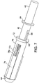
- FIG. 7 shows the annular ring 72 in an end position whereat the front face of the annular ring 72 abuts an annular end face (not visible in FIG. 7 ) of the applicator body 76.
- the only interference section of the hole coating applicator 40c are the LMA pads 54a-54c and not the conical nose 44.
- the nose 44 guides the hole coating applicator 40c into the hole.
- the diameter of the base 44a of nose 44 is smaller than the hole diameter.
- the contact with the CFRP hole 20 occurs after the nose insertion.
- the LMA pads 54a-54c move down the inclined paths and compress the retention spring 50 on the back side until the outer peripheral surfaces 74 of the LMA pads 54a-54c contact the hole 20.
- the spring compression provides a steady outward radial force to sustain the firm contact between the LMA pads 54a-54c and the CFRP hole.
- the magnitude of the compressive force produces frictional forces sufficient to abrade the LMA pads 54a-54c during rotation of the hole coating applicator 40c, causing the deposition of LMA particles on the surface defining hole 20. This deposition is continued until a desired thickness of the coating 12 is achieved.
- the applicator body 84 includes a non-flexural portion 85, a first flexural element 90 and a second flexural element 106.
- the non-flexural portion 85 is fixedly coupled to the distal end of the shaft 42.
- the flexural element 90 is configured to bend relative to the non-flexural portion 85 due to flexure of a first flexural hinge 86.
- the flexural element 106 is configured to bend relative to the flexural element 90 due to flexure of a second flexural hinge 92 and a fourth flexural hinge 96.
- the applicator body 84 further includes a flexural element 108 and a flexural element 124.
- the flexural element 108 is configured to bend relative to the non-flexural portion 85 due to flexure of a flexural hinge 88.
- the flexural element 124 is configured to bend relative to the flexural element 108 due to flexure of flexural hinges 110 and 114.
- the flexural hinge 88 directly connects the flexural element 108 to the non-flexural portion 85.
- the flexural hinges 110 and 114 connect the flexural elements 108 and 124 to each other.
- the applicator body 84 further includes a flexural element 120 and a flexural element 122.
- the flexural element 102 is configured to bend relative to the non-flexural portion 85 due to flexure of flexural hinges 98, 94, 92, and 86; the flexural element 104 is configured to bend relative to the non-flexural portion 85 due to flexure of flexural hinges 100, 94, 92, and 86; the flexural element 120 is configured to bend relative to the non-flexural portion 85 due to flexure of flexural hinges 116, 112, 110, and 88; and the flexural element 122 is configured to bend relative to the non-flexural portion 85 due to flexure of flexural hinges 118, 112, 110, and 88.
- the monolithic hole coating applicator 40d has self-aligning and centering capabilities due to the flexural hinges.
- the hole coating applicator 40d further includes a first LMA pad 54a attached to the outer peripheral surface of flexural elements 102 and 104 and intersection 1a.
- the hole coating applicator 40d can include a second LMA pad 54b attached to the outer peripheral surface of flexural elements 120 and 122 and intersection 1c.
- the flexural elements 102 and 104 in an unflexed state may be tilted slightly toward the center axis of the hole coating applicator 40d so that radially outward bending during rotation produces alignment of the LMA pads 54a and 54b.
- the same is true for flexural elements 120 and 122.
- the speed of rotation of shaft 42 should be sufficiently high that the magnitude of the resulting frictional forces produced at the interface between the LMA pads 54a and 54b and the hole will cause the LMA to abrade and deposit on the hole. This deposition is continued until a desired thickness of the hole coating is achieved.
- the applicator body 84 includes a non-flexural portion 180, a radial flexural element 182 and a radial flexural element 184.
- the non-flexural portion 180 is fixedly coupled to the distal end of the shaft 42.
- the radial flexural element 182 is configured to bend relative to the non-flexural portion 180 due to flexure of an axial flexural hinge 186.
- the radial flexural element 184 is configured to bend relative to the non-flexural portion 180 due to flexure of an axial flexural hinge 188.
- the radial flexural element 182 is separated from the shaft 42 by a gap 190 and is separated from the non-flexural portion 180 by a gap 192.
- the radial flexural element 184 is separated from the shaft 42 by a gap (not visible in FIG. 20 ) and is separated from the non-flexural portion 180 by a gap 194.
- Suitable LMAs include alloys of two or more elements of the following: bismuth, indium, tin, lead, and antimony.
- a preferred LMA is a ternary alloy consisting of a mixture of bismuth (preferably more than 50%), indium and tin. Due to its softness, the LMA performs like a solid lubricant and fastener insertion is easier with lower insertion force for interference fit.
- FIG. 11 is a circuit diagram representing a resistance measuring circuit 36 designed to measure a resistance that is indicative of the thickness of coating 12 applied in a joint hole 20 formed in a composite layer 30. (The composite material on the other side of the hole 20 is not shown in FIG. 11 .)
- the resistance measuring circuit 36 is measuring the effective resistance of a coating 12 made of LMA and the random parallel resistance of the carbon fibers in a composite layer 30 made of CFRP in series. This measurement is accomplished by placing a capacitive sensing pad 38 having an annular shape in contact with an annular portion of the surface of the composite layer 30 that surrounds the hole 20.
- the capacitive sensing pad 38 includes a dielectric coating 39 (see FIG.
- an electrically conductive sensing element e.g., a copper plate, film or coating
- the dielectric coating 39 can maintain a space between the sensing element and the composite layer 30 to prevent a short circuit.
- the sensing pad 38 and the confronting portion of the composite layer 30 form a capacitor having a capacitance C1.
- the resistance measuring circuit 36 includes a pair of terminals A and B which form a modified resistance-capacitance (RC) Wheatstone bridge 130.
- a Wheatstone bridge is an electrical circuit used to measure an unknown electrical resistance by balancing two legs of a bridge circuit, one leg of which includes the unknown component.
- the sensing pad 38 is electrically connected to terminal B.
- the terminal A is connected to one side of a capacitor 160 having a capacitance C2.
- the other side of capacitor 160 is connected in series to a resistance R2, which is in turn electrically connected in series to the applicator 40 by way of a junction 170.
- the effective resistance of coating 12 and composite layer 30 in series is represented by a variable resistance R9 (hereinafter "effective resistance R9") in FIG. 11 .
- the voltage difference between the A-B terminals of modified RC Wheatstone bridge 130 is input to an operational amplifier 138.
- the output terminal 7 of operational amplifier 138 is connected to a negative input terminal 9 of an operational amplifier 140 by way of a rectifier 164 (although represented as a single diode, rectifier 164 may include multiple diodes) and a resistance R7 in series.
- the operational amplifier 138 operates as a comparator which compares the effective resistance R9 (which is variable) to resistance R2 (which is adjustable). More specifically, resistance R2 can be heuristically evaluated over many separate measurements of what one might consider a satisfactory interface.
- the resistance R2 can be easily adjusted with a series of predefined resistances R2, very similar to range selection of a multimeter.
- junction 166 located between the high-frequency alternating current source 136 and ground.
- junction 166 is electrically connected: to a junction 168 (situated between junction 170 and the high-frequency alternating current source 136) by way of a resistance R6; to terminal A by way of a resistance R4; and to terminal B by way of a resistance R3.
- the output terminal of operational amplifier 140 is electrically connected to the negative input terminal 9 of operational amplifier 140 by way of a capacitor 162 having a capacitance C3 and by way of a resistance R8 in parallel.
- the resistance R7, operational amplifier 140, capacitor 162, and resistance R8 form an integrator 134.
- the output terminal of operational amplifier 140 is also electrically connected to a first output terminal 142.
- a second output terminal 144 is electrically connected to ground by way of junction 166.
- the output voltage V out between first and second output terminals 142 and 144 is the output voltage of operational amplifier 140.
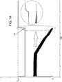
- the operational amplifier 140 performs the mathematical operation of integration with respect to time; that is, the output voltage is proportional to the input voltage integrated over time, as seen in FIG. 14 , which shows the output voltage V out versus time as the thickness of the coating 12 being deposited in the hole 20 increases.
- FIG. 13 is a graph of the output voltage V out of the circuitry depicted in FIG. 11 versus time that shows how the output voltage V out varies in dependence on whether the variable effective resistance R9 is equal to fixed resistance R2 or not.
- the effective resistance R9 solely depends on the fiber connectivity at the hole interface. This means that the resistance of LMA alone is negligible compared to the resistance of the carbon fibers and, because the current goes through the thin layer of LMA perpendicularly, the resistance becomes practically zero. In other words, the resistance of the interface with the LMA depends on fiber connectivity only and is independent of the LMA application steps.
- FIG. 15 is a block diagram identifying components of a system 125 for monitoring the thickness of a coating 12 made of electrically conductive material deposited on a surface defining a hole 20 in a composite layer 30 including CFRP by measuring an effective resistance at the hole interface 1.
- the system 125 includes an apparatus 126 that is under the command of a control computer 128.
- the apparatus 126 includes a support structure 146, bearings 148, a spindle 150, a motor 152, a chuck 154, a hole coating applicator 40; and a low-melting alloy pad (not shown in FIG. 15 ).
- the bearings 148 are supported by the support structure 146.
- the spindle 150 is rotatably supported by the bearings 148.
- the motor 152 is mechanically coupled to the spindle 150 for driving rotation of the spindle 150.
- the chuck 154 is coupled to a distal end of the spindle 150.
- the hole coating applicator 40 includes a shaft (not shown in FIG. 15 ) made of a material that is not a low-melting alloy and clamped by the chuck 154.
- the low-melting alloy pad is supported by the shaft and radially movable relative to the shaft.
- the support structure 146 may take the form of an articulated robot arm (not shown in the drawings).
- the applicator 40 applies coating 12 on a surface defining a hole 20 formed in the composite layer 30.
- a sensing pad 38 is capacitively coupled to the composite layer 30.
- the resistance measuring circuit 36 (shown in detail in FIG. 11 ) can be connected to the applicator 40 (which is made of electrically conductive metal alloy) and to the sensing pad 38 (which is made of electrically conductive metal or metal alloy).
- the output voltage V out from the resistance measuring circuit 36 is received by the control computer 128, which commands the motor controller 158 in dependence on the output voltage level.
- the control computer 128 does not send a command to the motor controller 158 instructing the motor controller 158 to turn off the motor 152.
- the control computer 128 sends a command to the motor controller 158 instructing the motor controller 158 to turn off the motor 152.
- FIG. 17 is a flowchart identifying steps of a method 200 for applying a coating 12 on a surface of a lamination of plies of fiber-reinforced plastic material.
- the surface (which may define a hole 20 or form an edge 21) of the lamination includes exposed ends of reinforcement fibers.
- the method 200 includes selecting an electrically conductive material that is abradable in a solid state by rubbing against the surface of the lamination having exposed ends of reinforcement fibers (step 202).
- the method 200 further includes rubbing the electrically conductive material against the surface of the lamination to cause particles of electrically conductive material to be abraded and deposited on the surface of the lamination (step 204).
- FIG. 18 is a flowchart identifying steps of a method 210 for applying a coating 12 on a surface defining a hole 20 of a composite layer 30 using the system 125 depicted in FIG. 15 .
- the sensing pad 38 of the resistance measuring circuit 36 is capacitively coupled to the composite layer 30 (step 212).
- a contact terminal of the resistance measuring circuit 36 is electrically connected to the hole coating applicator 40 (step 214).
- the hole coating applicator 40 is inserted in the hole 20 (step 216).
- the hole coating applicator 40 is rotated in the hole 20 while the abradable electrically conductive material is in contact with the hole 20 to cause particles of the electrically conductive material to be abraded and deposited on the surface defining hole 20 (step 218).
- An alternating current is supplied from the resistance measuring circuit 36 to the hole coating applicator 40 by way of the contact terminal (step 220). While the alternating current is being supplied, the resistance measuring circuit 36 outputs a characteristic voltage signal to the control computer 160 when an amplitude of a signal from the sensing pad 38 reaches a value that is indicative that a desired amount of electrically conductive material has been deposited on the surface defining hole 20 (step 222). In response to receipt of the characteristic voltage signal, the control computer 160 sends a control signal to the motor controller 158 instructing it to turn off the motor 152 (step 224), which causes the hole coating applicator 40 to stop rotating. The hole coating applicator 40 is then removed from the coated hole 22 (step 226).
- an alternating current is supplied from the resistance measuring circuit 36 to the hole coating applicator 40 (step 238). While the alternating current is being supplied, a characteristic voltage signal is output from the resistance measuring circuit 36 if an amplitude of a signal from the sensing pad 38 reaches a value that is indicative that a desired amount of electrically conductive material has been deposited on the surface defining the hole 20 (step 240). Rotation of the hole coating applicator 40 is resumed if the resistance measuring circuit 36 outputs a voltage signal that is not the characteristic voltage signal (step 242).
- FIG. 12 is a diagram showing a sensing pad 38 (only partly shown) placed around a coated hole 22.
- the sensing pad 38 has the shape of an annular ring and is preferably placed concentric to the hole 20.
- FIG. 12 shows the fastener 2 being held by the fastener inserter 156 during measurement of the effective resistance R9.
- the same resistance measuring circuit 36 can be used. In this scenario, terminal A of the resistance measuring circuit 36 is connected to the fastener 2 (which is made of electrically conductive metal alloy) while terminal B is connected to the sensing pad 38.
- FIG. 16 is a diagram identifying components of a system for monitoring the thickness of an electrically conductive coating 12 deposited on an edge 21 of a composite layer 30 including CFRP by measuring an effective resistance with reference to a near-edge fastener 2.
- the composite layer 30 includes a stack of plies, the carbon fibers in each ply being mutually parallel to each other, but different plies having different fiber orientations. In the example depicted in FIG.
- sensing pad refers to the capacitive element over the CFRP surface in FIG. 11 or overlying the coating 12 in FIG. 16 .
- the sensing pad 38 has a dielectric coating 39 to prevent any incidental short circuit.
- a simplest shape is a flat circular plate with a central hole (referred to herein as an "annular ring").
- the hole allows the applicator insertion to the CFRP through it.
- no hole is necessary and the plate size may vary based on the ply thickness.
- the effective surface area and the combined dielectric constant are the key variables that determine the effective capacitance.
- the resistance measuring circuit 36 can be used to measure a contact resistance at an interface of an electrically conductive coating and a cross-ply surface of a composite layer made of fiber-reinforced plastic having electrically conductive fibers.
- the cross-ply surface may define a hole in or form an edge of the composite layer.
- a sensing pad is placed on a surface of the composite layer, as shown in FIG. 11 .
- a sensing pad is placed on a coated edge of the composite layer, as shown in FIG. 16 .
- the cross-ply surface of the composite layer defines a hole and the electrically conductive body is a fastener or a hole coating applicator inserted in the hole.
- the electrically conductive coating is disposed on an edge of the composite layer near the fastener. The method may further include: depositing electrically conductive material on the hole to form the electrically conductive coating until a time when the characteristic voltage signal is output; and ceasing depositing of electrically conductive material on the hole after the characteristic voltage signal is output.
Landscapes
- Chemical & Material Sciences (AREA)
- Engineering & Computer Science (AREA)
- Mechanical Engineering (AREA)
- Materials Engineering (AREA)
- Organic Chemistry (AREA)
- Metallurgy (AREA)
- Chemical Kinetics & Catalysis (AREA)
- General Engineering & Computer Science (AREA)
- Composite Materials (AREA)
- Manufacturing & Machinery (AREA)
- Life Sciences & Earth Sciences (AREA)
- Wood Science & Technology (AREA)
- Coating Apparatus (AREA)
- Application Of Or Painting With Fluid Materials (AREA)
- Other Surface Treatments For Metallic Materials (AREA)
Abstract
Description
- This disclosure generally relates to the use of fasteners to secure two or more structures or workpieces (at least one of which is made of composite material, such as fiber-reinforced plastic) in a manner such that interference fit of the fasteners within joint holes (hereinafter "holes") in the structure may be achieved. In particular, this disclosure relates to apparatus and methods for fastening a layer of composite material to another layer of material using an interference fit fastener assembly having a bolt or a pin and a mating part (e.g., a nut or a collar).
- As used herein, the category "mating parts" comprises internally threaded nuts and collars and swaged collars. As used herein, the category "fasteners" includes bolts, pins, rivets, and/or any other suitable device. As used herein, the term "external projections" should be construed broadly to encompass at least the following types: (1) external threads and (2) external annular rings. As used herein, the term "hole" means a surface that bounds a space and connects openings in opposing surfaces of a part. In the context of fiber-reinforced plastic material, the surface bounding the space is formed by resin and fibers.
- At least one method for fastening multiple layers of material together is to clamp up the layers, drill holes, and then insert fasteners into the holes to secure the layers together. The fasteners are usually inserted in a net or clearance fit in the receiving holes in the layers. For many applications, this will be sufficient. However, when the assembled structure is subjected to cyclic loading, the looseness of the fit of the fasteners within their holes can result in continual working of the fasteners within their holes.
- Additional challenges are presented when one or more of the fastened layers are made of composite material. For example, carbon fiber-reinforced plastic (CFRP) is considerably less conductive than metal. Electrical current is conducted through carbon fibers in the CFRP structure. Any discontinuity between the carbon fibers and the metallic fastener in the CFRP hole is undesirable.
- An interference fit of the fastener (hereinafter "interference fit fastener") in the hole may effectively reduce discontinuities due to cyclic loading of the assembled structure. Interference creates a tighter joint that reduces movement, resulting in enhanced fatigue performance. Additionally, interference fit fasteners may help dissipate electrical current.
- One method for minimizing the variation in interference fit for sleeveless fasteners used to fasten a layer of composite material (hereinafter "composite layer") to another layer of material (e.g., a metallic layer or another composite layer), while enhancing the electrical conductivity between the fibers of the composite material (e.g., CFRP) and the metallic fastener, involves coating the hole with molten low-melting alloy. However, the molten low-melting alloy tends to be repelled by the fibrous CFRP surface due to the high surface tension of the molten low-melting alloy. This can be due to extreme curvatures at the fiber level dimension. The surface tension of the low-melting alloy can inhibit spreading at this scale.
- Although various examples of methods, apparatus and applicators for coating joint holes in a composite layer by abrasion of solid electrically conductive material will be described in some detail below, one or more of those examples may be characterized by one or more of the following aspects.
- One aspect of the subject matter disclosed in detail below is a method for applying a coating on a surface of a lamination of plies of fiber-reinforced plastic material, which surface has exposed ends of reinforcement fibers, the method comprising: selecting an electrically conductive material that is abradable in a solid state by rubbing against the surface of the lamination having exposed ends of reinforcement fibers; and rubbing the electrically conductive material against the surface of the lamination to cause particles of electrically conductive material to be abraded and deposited on the surface of the lamination. In accordance with some examples, the surface of the lamination is a hole that extends through multiple plies. In accordance with other examples, the surface of the lamination is an edge that has been cut through multiple plies. Preferably the solid electrically conductive material is a low-melting alloy (LMA), which is also commonly referred to as a "fusible alloy". As used herein, the term "low-melting alloy" refers to alloys having a melting temperature in a range greater than 170°F and less than 300°F.
- Another aspect of the subject matter disclosed in detail below is an apparatus comprising: a support structure; bearings supported by the support structure; a spindle rotatably supported by the bearings; a motor mechanically coupled to the spindle for driving rotation of the spindle; a chuck coupled to the spindle; and a hole coating applicator comprising a shaft made of a material that is not LMA and clamped by the chuck, and a LMA pad that is supported by the shaft and radially movable relative to the shaft. In accordance with some examples, the hole coating applicator further comprises a flexural element that is configured to bend relative to the shaft due to flexure of a flexural hinge, and the LMA pad is attached to the flexural element. In accordance with other examples, the hole coating applicator further comprises: a camming surface; a camming block that carries the LMA pad and has an inclined surface in contact with the camming surface; and a spring that exerts an axial spring force on the camming block, wherein the camming surface deflects the camming block to move radially outward when the axial spring force is exerted on the camming block.
- A further aspect of the subject matter disclosed in detail below is a hole coating applicator comprising: a shaft made of a metal alloy that is not a LMA and having a distal end; an applicator body made of a metal alloy that is not a LMA, the applicator body comprising a non-flexural portion that is fixedly coupled to a portion of the shaft located at a distance from the distal end of the shaft and a flexural element that is configured to bend relative to the non-flexural portion due to flexure of a flexural hinge; and a pad made of abradable material (e.g., LMA) attached to the flexural element.
- Yet another aspect of the subject matter disclosed in detail below is a hole coating applicator comprising: a shaft made of a material that is not a LMA; an applicator body coupled to the shaft, made of a material that is not a LMA and comprising a camming surface; a camming block made of a material that is not a LMA and having an inclined surface that confronts the camming surface; a LMA pad attached to the camming block, the LMA pad having an outer peripheral surface that is exposed; and a spring that exerts an axial spring force on the camming block, wherein the camming surface deflects the camming block to move in a direction having a radially outward component when the camming block is moved by the axial spring force.
- A further aspect is a structural assembly comprising: a composite layer having a hole or edge with a surface that has concavities; and a coating adhered to the surface of the hole or edge and filling the concavities, wherein the composite layer comprises fibers made of electrically conductive material and the coating comprises an aggregation of abraded particles of LMA deposited in a cold state. In accordance with some examples, the coating further comprises a continuous thin film of LMA overlying the aggregation of particles. Suitable LMAs include alloys of two or more elements of the following: bismuth, indium, tin, lead, and antimony. A preferred LMA is a ternary alloy consisting of a mixture of bismuth (preferably more than 50%), indium and tin.
- Other aspects of systems, apparatus and methods for coating joint holes in a composite layer by abrasion of solid electrically conductive material are disclosed below.
- The features, functions and advantages discussed in the preceding section may be achieved independently in various examples or may be combined in yet other examples. Various examples will be hereinafter described with reference to drawings for the purpose of illustrating the above-described and other aspects. None of the diagrams briefly described in this section are drawn to scale.
-
FIG. 1 is a diagram representing a partially sectioned view of an assembly including composite and metallic structures gripped by a sleeveless interference fit fastener assembly. -
FIG. 2 is a cutaway diagram representing a view of portions of a hole coating applicator in accordance with a first example. -
FIG. 3 is a cutaway diagram representing a view of portions of a hole coating applicator in accordance with a second example. -
FIG. 4 is a cutaway diagram representing a view of portions of a hole coating applicator in accordance with a third example. -
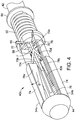
FIG. 4A is a cutaway diagram similar toFIG. 4 except that some components (indicated by dashed lines) of the hole coating applicator in accordance with the third example have been removed to reveal additional internal structure and some hatching has been omitted to avoid clutter in the drawing. -
FIG. 5 is a cutaway diagram representing a different view of portions of the hole coating applicator in accordance with the third example. -
FIG. 6 is a diagram representing another view of the hole coating applicator in accordance with the third example except that a sliding annular ring has been removed to reveal a transverse pin that slides in a slot formed in the shaft of the hole coating applicator. -
FIG. 7 is a diagram representing a view similar to the view inFIG. 6 , but with the sliding annular ring in place adjacent an end stop formed by an applicator body integrally formed with or joined to the hole coating applicator shaft. -
FIG. 8 is a diagram representing a view of the applicator body and the sliding annular ring in accordance with the third example. -
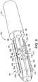
FIGS. 9 and10 are diagrams representing different views of a hole coating applicator in accordance with a fourth example. -
FIG. 10A is a diagram representing a magnified view of the portion of the hole coating applicator within thedashed ellipse 10A indicated inFIG. 10 . -
FIG. 11 is a circuit diagram representing electrical circuitry of a resistance measuring probe designed to measure the thickness of an electrically conductive coating applied in a joint hole formed in a layer of composite material. -
FIG. 12 is a diagram showing the placement of a sensing pad around a coated hole in which a fastener is being inserted for use in measuring the thickness of the electrically conductive coating. -
FIG. 13 is a graph of the output voltage Vout of the circuitry depicted inFIG. 11 versus time that shows how the output voltage Vout varies in dependence on whether the variable resistance R9 is equal to fixed resistance R2 or not. -
FIG. 14 includes two graphs of voltage versus time: the upper graph shows how the output voltage Vout changes significantly when the hole resistance reaches the desired value; the lower graph shows how the A-B bridge output voltage decreases as the hole resistance approaches the desired value. -
FIG. 15 is a block diagram identifying components of a system for monitoring the thickness of an electrically conductive coating deposited in a joint hole in a composite layer including CFRP by measuring an effective resistance at the hole interface. -
FIG. 16 is a diagram identifying components of a system for monitoring the thickness of an electrically conductive coating deposited on an edge of a composite layer including CFRP by measuring an effective resistance with reference to a near-edge fastener. -
FIG. 17 is a flowchart identifying steps of a method for applying a coating on a surface of a lamination of plies of fiber-reinforced plastic material. -
FIG. 18 is a flowchart identifying steps of a method for applying a coating on a surface that defines a hole in a composite layer using the system depicted inFIG. 15 . -
FIG. 19 is a flowchart identifying steps of a method for measuring a contact resistance at an interface of an electrically conductive coating and a cross-ply surface of a composite layer made of fiber-reinforced plastic having electrically conductive fibers. -
FIG. 20 is a diagram representing a view of portions of a hole coating applicator in accordance with a fifth example. -
FIG. 21 is a flowchart identifying steps of a method for measuring a contact resistance at an interface of an electrically conductive coating and a cross-ply surface of a composite layer made of fiber-reinforced plastic having electrically conductive fibers. - Reference will hereinafter be made to the drawings in which similar elements in different drawings bear the same reference numerals.
- The subject matter disclosed in some detail below is directed to methods, apparatus and applicators for coating joint holes in a composite layer by abrading solid electrically conductive material, such as low-melting alloy (LMA). Low-melting alloy has low hardness due to its lower intermolecular strength and can be delivered to the joint hole in the composite material directly at room temperature. After a metallic fastener has been inserted in the coated hole, the coating can enhance the electrical conductivity between the fibers of the composite material (e.g., CFRP) and the metallic fastener, while minimizing the variation in interference fit for sleeveless fasteners used to fasten a layer of composite material (hereinafter "composite layer") to another layer of material (e.g., a metallic layer or another composite layer). The solid electrically conductive material can be deposited on edges as well.
- More particularly, the coating technique proposed herein can circumvent the difficulties attributable to the molecular repulsive force produced when molten LMA wets a rough surface of a CFRP layer. In accordance with some examples, the size of LMA particulates on the surface is reduced by applying the LMA cold (e.g., at room temperature) and depositing a thin layer of LMA through abrasion (similar to a chalk-on-board effect). This primary layer of LMA can reduce the effective curvature of the coated hole formed by the LMA and produces a repeatable and consistent coating over the CFRP surface. The proposed method can produce a distinct microstructure of LMA on CFRP that significantly improves the LMA/CFRP interface quality and connectivity. The method may also significantly improve the LMA coating quality and quantity when applied to a titanium fastener.
- Optionally, a second deposit of LMA in a molten state can be applied. In that event, the molten LMA easily spreads on the primary layer of LMA to create a closer-to-perfect final coating.
- The apparatus used to practice the above-described method includes a rotating applicator configured to coat a joint hole by depositing a solid electrically conductive material (e.g., LMA) through friction. The hole coating applicator includes a shaft which can be gripped by a chuck mounted on the end of a spindle of a stationary drilling machine or a drilling tool attached to a robot or other automated apparatus.
- In accordance with some examples, the hole coating applicator further includes one or more camming blocks that carry respective pads made of LMA (hereinafter "LMA pads") configured to rub against a hole and a spring that exerts an axial spring force on the camming blocks. The hole coating applicator further includes respective camming surfaces that cause the camming blocks to move radially outward when the axial spring force is exerted on the camming blocks in an axial direction. During rotation of the hole coating applicator, the LMA is pressed against the hole with sufficient force to abrade LMA particles and deposit the LMA particles on the CFRP that forms the joint hole until a desired coating thickness is achieved.
- In accordance with other examples, the hole coating applicator further includes flexural elements that have the capability to bend relative to the shaft at respective flexural hinges, and respective LMA pads attached to the flexural elements. Each LMA pad has an outer peripheral surface that is disposed radially outward further from the shaft than any portion of the hole coating applicator not made of LMA. During rotation of the hole coating applicator, the flexural elements press the LMA against the hole with sufficient force to abrade LMA particles and deposit them on the CFRP until a desired coating thickness is achieved.
- As used herein, the term "bend", in the context of a flexural element connected to another element by way of a flexural hinge, means to change the angle of the flexural element relative to the other element due to flexure of the flexural hinge, not to bend along the length of the flexural element. If a flexural element is connected to another element by way of multiple flexural hinges, then the flexural element is configured to bend relative to the other element due to flexure at one or more of the multiplicity of flexural hinges. To ensure that a sufficient amount of LMA is applied in a particular composite joint installation, a real-time monitoring system can be employed to verify that the contact resistance is within an acceptable range. If the capacitive coupling described herein is utilized, the effective resistance depends only on the hole interface resistance (i.e., the effective resistance is LMA quality/quantity dependent). The circuits described herein include a capacitive coupling segment that allows the monitoring system to measure resistance with one contact point only. A feedback loop is used to control the LMA application process (applicator insertion and rotation) and confirm completion to a satisfactory resistance level based on the response by the monitoring system. By depositing LMA to form a coating on the joint hole, concurrently measuring the effective resistance of the LMA and carbon fibers in series, and then ceasing deposition when a specified effective resistance is achieved, at least a minimum acceptable electrical conductivity at the hole/fastener interface can be achieved in the final structural assembly. Various examples of systems, apparatus, and methods for coating joint holes in a composite layer by abrasion of solid electrically conductive material will now be described in detail for the purpose of illustration. The resulting coating can minimize interference fit variation and can enhance electrical conductivity in an interference fit fastener assembly. At least some of the details disclosed below relate to optional features or aspects, which in some applications may be omitted without departing from the scope of the claims appended hereto.
- One illustrative example of a structural assembly including a first structural element made of metallic material (e.g., a metal alloy) attached to a second structural element made of composite material (e.g., fiber-reinforced plastic) by means of a sleeveless interference fit fastener assembly will now be described in detail with reference to
FIG. 1 . In accordance with that example, the fastener includes a pin, and the mating part includes a swaged collar that is interengaged with the external projections of the mating portion of the pin. However, the concepts disclosed herein also have application in other examples in which the fastener includes a bolt, and the mating part includes a nut having internal threads that are interengaged with the external projections of the mating portion of the bolt. -
FIG. 1 is a diagram representing a partially sectioned view of astructural assembly 14 including acomposite layer 30 having ahole 20 with a surface that has crevices. Thestructural assembly 14 also includes acoating 12 adhered to thehole 20 and filling the crevices. Thecoating 12 defines a circular cylindricalcoated hole 22. Thecomposite layer 30 has fibers made of electrically conductive material, and thecoating 12 includes or is a LMA, which was applied while in a molten state. In the example depicted inFIG. 1 , thestructural assembly 14 further includes ametallic layer 32 disposed adjacent to and in contact with thecomposite layer 30. - The
structural assembly 14 can also include a sleeveless interferencefit fastener assembly 28 having afastener 2 and a swagedcollar 34. Thefastener 2 includes ashank 6, a threadedportion 8, and atransition portion 10. In alternative examples, thefastener 2 may have external annular rings instead of external threads. AlthoughFIG. 1 depicts afastener 2 having a countersunk (i.e., flush)head 4, thefastener 2 may in the alternative have a protruding head. An interference fit is achieved by thecoated hole 22 having an inner diameter that is less than the outer diameter of the shank 6 (e.g., a difference of a few thousandths of a centimeter (an inch)). - The
fastener 2 shown inFIG. 1 is inserted into thecoated hole 22 and the unswaged collar (not shown inFIG. 1 ) is placed over a portion of thefastener 2. During the installation cycle of thefastener 2, the unswaged collar (in the form of a loose-fitting metal ring) is deformed around thefastener 2, which has locking grooves on the threadedportion 8, to form swagedcollar 34. Thefastener 2 and swagedcollar 34 combine to form thefastener assembly 28. The bolts and pins are preferably made of a metal alloy such as titanium alloy, aluminum alloy, Inconel, or corrosion-resistant steel. The collars are preferably made of titanium alloy, aluminum alloy, or corrosion-resistant steel. - This disclosure proposes to improve the quality and connectivity of the coating/composite layer interface inside a joint hole (e.g., a joint hole of the type depicted in
FIG. 1 ) by applying solid LMA that has a low abrasion resistance, rather than by applying molten LMA, to the surface of the composite material that forms thehole 20. Optionally, molten LMA can be applied over the solid LMA deposited in the hole to achieve a coated hole having a surface that is smoother than what can be achieved using solid LMA alone. - The process briefly described in the preceding paragraph may be applied to every joint hole in a composite layer to be included in a stack of layers to form a
structural assembly 14, such as a structural part (e.g., of an aircraft). After all holes in all layers of composite material to be included in thestructural assembly 14 have been coated with LMA, the layers of composite material and any other layers not made of composite material are placed in a stack such that the holes in the respective stacked layers are aligned. Arespective fastener 2 is pre-heated (to liquefy the surface of the solidified material to enable hydroplaning during insertion, thereby reducing resistance) and then inserted into thecoated hole 22 in thecomposite layer 30 with an interference fit. The swagedcollar 34 is then coupled to therespective fastener 2. In each instance, at least a portion of theshank 6 of thefastener 2 is surrounded by thecoating 12 made of electrically conductive material. - Various examples of apparatus for applying solid LMA in a joint hole, such as the
hole 20, will now be disclosed with reference toFIGS. 2-10 (andFIGS. 4A and10A ). Each of these examples includes a hole coating applicator 40 (seeFIG. 15 ) that may be coupled to the end effector (e.g., a chuck 154) of a machine that has a rotatable and verticallydisplaceable spindle 150. The common aspect of the examples disclosed below is that thehole coating applicator 40 is configured to coat a surface defining ahole 20 by depositing acoating 12 made of electrically conductive material through friction as thehole coating applicator 40 rotates. In accordance with some examples, thehole coating applicator 40 includes ashaft 42, which can be gripped by achuck 154 mounted on the end of aspindle 150 of a stationary drilling machine or a drilling tool attached to a robot or other automated apparatus. Thehole coating applicator 40 further includes one ormore LMA pads 54a-54c that contact the surface defining thehole 20 in thecomposite layer 30 with sufficient force to abrade theLMA pads 54a-54c as thespindle 150 rotates. As used herein, the term "LMA pad" refers to a solid block or layer of LMA having a thickness (which may vary along its length) and an outerperipheral surface 74 contoured to rub against thehole 20 during rotation of thehole coating applicator 40. -
FIG. 2 is a cutaway diagram representing a view of portions of ahole coating applicator 40a in accordance with a first example. Thehole coating applicator 40a includes ashaft 42 having a distal end and anapplicator body 46 fixedly coupled to an intermediate portion ofshaft 42. Theshaft 42 andapplicator body 46 are made of metallic alloys, neither of which is low-melting alloy (LMA). - In accordance with the first example, the
applicator body 46 includes anon-flexural portion 46a, a firstflexural element 46b and a secondflexural element 46d. Thenon-flexural portion 46a is fixedly coupled to the intermediate portion of theshaft 42 at a distance from the distal end of theshaft 42. The firstflexural element 46b is configured to bend relative to thenon-flexural portion 46a due to flexure of a firstflexural hinge 46c. The secondflexural element 46d is configured to bend relative to thenon-flexural portion 46a due to flexure of a secondflexural hinge 46e. The firstflexural hinge 46c directly connects the firstflexural element 46b to thenon-flexural portion 46a, and the secondflexural hinge 46e directly connects the secondflexural element 46d to thenon-flexural portion 46a. - The
hole coating applicator 40a further includes afirst LMA pad 54a attached to the firstflexural element 46b and asecond LMA pad 54b attached to the secondflexural element 46d. Each of the first andsecond LMA pads peripheral surface 58 that is preferably a section of a right circular cylindrical surface having a radius approximately equal to the radius of the hole 20 (shown inFIG. 1 ) to be coated with LMA particles. TheLMA pads flexural elements flexural elements hole 20 and the outerperipheral surfaces 58 contact thehole 20 during rotation of thehole coating applicator 40a. - The
hole coating applicator 40a can further include anose 44 having a truncated right circular conical surface. Thenose 44 is mounted to the distal end ofshaft 42. The tapered circumferential surface of thenose 44 facilitates passage of thenose 44 through thehole 20 during insertion ofhole coating applicator 40a. Thebase 44a of thenose 44 serves as an end stop for aretention spring 50, which is wrapped around a portion of theshaft 42 as seen inFIG. 2 . The other end of theretention spring 50 contacts aslider 48 that is slidably coupled to theshaft 42 in a vicinity of the distal ends of the first and secondflexural elements flexural element 46b has a circumferential portion of a first truncated right circularconical surface 52a, and the distal end of the secondflexural element 46d has a circumferential portion of a second truncated right circularconical surface 52b. Theslider 48 is in the form of a truncated right circular cone having a bore through which theshaft 42 is passed. The outer circumferential surface ofslider 48 is a truncated right circularconical surface 56 that abuts the circumferential portions of truncated right circularconical surfaces flexural elements slider 48 is in an abutting position. - The
retention spring 50 applies a spring force on theslider 48 that causes theslider 48 to slide axially in the direction indicated by arrow A inFIG. 2 . During this slider movement, the third truncated right circularconical surface 56 deflects the distal ends of the first and second flexural elements in opposite directions (indicated by arrows B and C inFIG. 2 ) away from theshaft 42. More specifically, the contact force exerted by theslider 48 causes the firstflexural element 46b to undergo an angular displacement through an angle β. This angular displacement is enabled by the flexure that occurs at the firstflexural hinge 46c. The secondflexural element 46d undergoes a similar angular displacement due to flexure of the secondflexural hinge 46e. In anticipation of these angular deflections, the outerperipheral surfaces 58 of theLMA pads peripheral surfaces 58 will be parallel to the hole to be coated, not tilted. This in turn can ensure that the entirety of each outerperipheral surface 58 is in contact with the hole and subject to abrasion when thehole coating applicator 40a is rotated while inside the hole. Preferably the axis ofshaft 42 will be coaxial with the axis of the hole during rotation of thehole coating applicator 40a. -
FIG. 3 is a cutaway diagram representing a view of portions of ahole coating applicator 40b in accordance with a second example. Thehole coating applicator 40b includes ashaft 42 having a distal end, anose 44 attached to the distal end ofshaft 42, and abackstop flange 64 attached to an intermediate portion ofshaft 42 at a distance from thenose 44. Thehole coating applicator 40b further include a pair of camming half-bodies shaft 42. Each of the camming half-bodies respective camming surface respective camming surfaces bodies hole coating applicator 40b further includesrespective LMA pads bodies LMA pads peripheral surfaces 74, which are right circular cylindrical surfaces having a radius that matches the radius of the hole to be coated, as previously described. Each of theLMA pads - The
hole coating applicator 40b further includes aretention spring 50, which is wrapped around a portion of theshaft 42 as seen inFIG. 3 . Thebackstop flange 64 serves as an end stop for theretention spring 50. The other end of theretention spring 50 contacts an end face of the camming half-body 60a. Theretention spring 50 applies a spring force on the camming half-body 60a that urges the camming half-body 60a to move axially in the direction indicated by arrow F inFIG. 3 . During this movement, thecamming surface 62b of camming half-body 60b deflects the camming half-body 60a so that the movement of the camming half-body 60a (indicated by arrow D inFIG. 3 ) has both an axial component and a radially outward component. In addition, thecamming surface 62a of camming half-body 60a cams the camming half-body 60b so that camming half-body 60b also moves radially outward in a direction opposite to the radially outward movement of camming half-body 60a (indicated by arrow E inFIG. 3 ). The effect of this radial expansion of the camming half-bodies LMA pads hole coating applicator 40b. The magnitude of the pressure exerted is designed to produce frictional forces sufficient to abrade the LMA pads during rotation of thehole coating applicator 40b, causing the deposition of LMA particles on the hole. This deposition is continued until a desired thickness of thecoating 12 in ahole 20 is achieved.FIG. 4 is a cutaway diagram representing a view of portions of ahole coating applicator 40c in accordance with a third example.FIG. 4A is a cutaway diagram similar toFIG. 4 except that some components (indicated by dashed lines) of thehole coating applicator 40c have been removed to reveal additional internal structure and some hatching has been omitted to avoid clutter in the drawing. - As seen in
FIG. 4 , thehole coating applicator 40c includes ashaft 42, anapplicator body 76 integrally formed with or joined to a distal end of theshaft 42, anose 44 attached to the distal end of theapplicator body 76, and abackstop flange 64 attached to an intermediate portion ofshaft 42 at a distance fromapplicator body 76. Thehole coating applicator 40c further include threecamming blocks 78a-78c, which are slidably coupled to theapplicator body 76 for sliding alongrespective camming surfaces applicator body 76. Only twocamming surfaces FIGS. 4A and5 . Eachcamming block 78a-78c has a respective inclined surface that confronts and contacts the camming surfaces 62a, 62b formed inside theapplicator body 76. -
FIG. 8 provides some insight into the construction of theapplicator body 76 in accordance with the third example. Thecamming block 78a has been removed to reveal thecamming surface 62a, which borders anopening 82 on three sides. Thepush rod link 70d passes through theopening 82. Movement of thecamming block 78a is constrained in transverse directions by a pair of mutually opposingplanar guide walls 80, only one of which is visible inFIG. 8 . Movement of thecamming block 78a is constrained in the radially outward direction by any suitable means. For example, theguide walls 80 may be provided with projections that engage linear channels formed in thecorresponding camming block 78a to prevent thecamming block 78a from falling out of theapplicator body 76. - Accordingly, any movement of the camming blocks 78a-78c toward the
nose 44 can result in the camming blocks 78a-78c moving parallel to the camming surfaces, which are inclined at an oblique angle relative to an axis ofshaft 42. In other words, the movement of eachcamming block 78a-78c has both an axial component and a radially outward component, as indicated by arrow D inFIG. 4 . The radial outward movements of the threecamming blocks 78a-78c will be referred to herein as "radial expansion". - Each of the camming blocks 78a-78c also has an outer peripheral surface that is a section of a right circular cylindrical surface. The
hole coating applicator 40c further includesrespective LMA pads 54a-54c (only LMApads FIG. 4 ) adhered to the outer peripheral surfaces ofcamming blocks 78a-78c respectively. TheLMA pads 54a-54c in turn have respective outerperipheral surfaces 74, which are right circular cylindrical surfaces having a radius that matches the radius of the hole to be coated, as previously described. Each of theLMA pads 54a-54c may have a constant thickness. - As best seen in
FIG. 4 , the trio ofcamming blocks 78a-78c are configured to move in unison in response to axial displacement of apush rod linkage 70 including apush rod 70a and three push rod links 70b-70d. Although pivotable couplings (e.g., revolute joints) are not shown in the drawings, the push rod links 70b-70d are pivotably coupled to one end of thepush rod 70a. The other ends of the push rod links 70b-70d are pivotably coupled to therespective camming blocks 78a-78c. An end portion of thepush rod 70a may be seated in an axial bore (not shown in the drawings) formed in theshaft 42 to constrain the movement of thepush rod 70a to be axial only. As thepush rod 70a is displaced axially toward thenose 44, the push rod links 70b-70d push therespective camming blocks 78a-78c along the respective inclined camming surfaces (only cammingsurfaces FIGS. 4A and5 ) to produce the desired radial expansion of theLMA pads 54a-54c into contact with the hole to be coated. - The
hole coating applicator 40b can further includes aretention spring 50, which is wrapped around a portion of theshaft 42 as seen inFIG. 4 . Thebackstop flange 64 serves as an end stop for theretention spring 50. The other end of theretention spring 50 contacts and exerts a spring force on anannular ring 72 that is slidable along the portion ofshaft 42 around which thespring 50 is wrapped. Theannular ring 72 is slidable between the end position depicted inFIGS. 4 ,4A and5 ), whereat the front surface of theannular ring 72 abuts an annular end face (hereinafter "end stop 77") of the applicator body 76 (end stop 77 is best seen inFIG. 6 ), and a position displaced from that end position (i.e., in a direction away from nose 44), whereat the retention spring is in a more compressed state than the state of compression when theannular ring 72 is at an end position. - The function of the
annular ring 72 may be gleaned from the fact that theannular ring 72 has two diametrically opposed radial bores that hold atransverse pin 66, seen inFIGS. 4 ,4A , and5 . As shown inFIG. 4 , thetransverse pin 66 is fixedly coupled to thepush rod 70a so that theannular ring 72 and thepush rod 70a move in tandem. This arrangement can enable the spring force of theretention spring 50 to axial displace thepush rod 70a toward thenose 44 by pushing theannular ring 72 toward its end position, which in turn displaces thepush rod linkage 70 toward thenose 44, thereby causing theLMA pads 54a-54c to radially expand into contact with the hole. - The portion of the
transverse pin 66 that spans the opening of theannular ring 72 is seated in aslot 68 formed in the portion ofshaft 42 around which theretention spring 50 is wrapped. Theretention spring 50 has been omitted from each ofFIGS. 5-7 in order to reveal theslot 68, which extends diametrically across and axially along theshaft 42.FIG. 5 shows thetransverse pin 66 seated inside theslot 68. Thetransverse pin 66 is axially movable in either direction inside theslot 68, as indicated by the double-headed arrow G.FIG. 6 shows thetransverse pin 66 with theannular ring 72 also omitted.FIG. 7 shows theannular ring 72 in an end position whereat the front face of theannular ring 72 abuts an annular end face (not visible inFIG. 7 ) of theapplicator body 76. - The only interference section of the
hole coating applicator 40c are theLMA pads 54a-54c and not theconical nose 44. Thenose 44 guides thehole coating applicator 40c into the hole. The diameter of thebase 44a ofnose 44 is smaller than the hole diameter. The contact with theCFRP hole 20 occurs after the nose insertion. At this point, due to interference and friction, theLMA pads 54a-54c move down the inclined paths and compress theretention spring 50 on the back side until the outerperipheral surfaces 74 of theLMA pads 54a-54c contact thehole 20. The spring compression provides a steady outward radial force to sustain the firm contact between theLMA pads 54a-54c and the CFRP hole. The magnitude of the compressive force produces frictional forces sufficient to abrade theLMA pads 54a-54c during rotation of thehole coating applicator 40c, causing the deposition of LMA particles on thesurface defining hole 20. This deposition is continued until a desired thickness of thecoating 12 is achieved. -
FIGS. 9 and10 are diagrams representing different views of ahole coating applicator 40d in accordance with a fourth example. Thehole coating applicator 40a includes ashaft 42 having a distal end and amonolithic applicator body 84 fixedly coupled to or integrally formed with the distal end ofshaft 42. (In the latter case, theshaft 42 andapplicator body 84 collectively form a monolithic structure.) Theshaft 42 andapplicator body 84 are made of a metallic alloy that is not a low-melting alloy (LMA). - In accordance with the fourth example, the
applicator body 84 includes anon-flexural portion 85, a firstflexural element 90 and a secondflexural element 106. Thenon-flexural portion 85 is fixedly coupled to the distal end of theshaft 42. Theflexural element 90 is configured to bend relative to thenon-flexural portion 85 due to flexure of a firstflexural hinge 86. Theflexural element 106 is configured to bend relative to theflexural element 90 due to flexure of a secondflexural hinge 92 and a fourthflexural hinge 96. The firstflexural hinge 86 connects theflexural element 90 to thenon-flexural portion 85, and the flexural hinges 92 and 96 connect theflexural elements applicator body 84 further includes a thirdflexural element 102. The thirdflexural element 102 is configured to bend relative to theflexural elements flexural hinge 94 and a sixthflexural hinge 98. Anotherflexural element 104 is configured to bend relative to theflexural elements flexural elements - In accordance with the fourth example, the
applicator body 84 further includes aflexural element 108 and aflexural element 124. Theflexural element 108 is configured to bend relative to thenon-flexural portion 85 due to flexure of aflexural hinge 88. Theflexural element 124 is configured to bend relative to theflexural element 108 due to flexure of flexural hinges 110 and 114. Theflexural hinge 88 directly connects theflexural element 108 to thenon-flexural portion 85. The flexural hinges 110 and 114 connect theflexural elements applicator body 84 further includes aflexural element 120 and aflexural element 122. Theflexural element 120 is configured to bend relative to theflexural elements flexural element 122 is configured to bend relative to theflexural elements flexural elements - Referring to
FIG. 10A , theintersection 1 a that connects the flexural hinges 94, 98, and 100 and theintersection 1b that connects the flexural hinges 92, 94, and 96 are connected byflexural hinge 94. Theintersection 1c that connects the flexural hinges 112, 116, and 118 and theintersection 1 d that connects the flexural hinges 110, 112, and 114 are connected byflexural hinge 112. - The foregoing structure enables every flexural element to bend relative to the
non-flexural portion 85 of theapplicator body 84 and relative to theshaft 42 due to flexure of one more flexural hinges. For example, theflexural element 102 is configured to bend relative to thenon-flexural portion 85 due to flexure of flexural hinges 98, 94, 92, and 86; theflexural element 104 is configured to bend relative to thenon-flexural portion 85 due to flexure of flexural hinges 100, 94, 92, and 86; theflexural element 120 is configured to bend relative to thenon-flexural portion 85 due to flexure of flexural hinges 116, 112, 110, and 88; and theflexural element 122 is configured to bend relative to thenon-flexural portion 85 due to flexure of flexural hinges 118, 112, 110, and 88. The monolithichole coating applicator 40d has self-aligning and centering capabilities due to the flexural hinges. - The
hole coating applicator 40d further includes afirst LMA pad 54a attached to the outer peripheral surface offlexural elements intersection 1a. Thehole coating applicator 40d can include asecond LMA pad 54b attached to the outer peripheral surface offlexural elements intersection 1c. During rotation of thehole coating applicator 40d whileapplicator body 84 is inside a hole, the flexural elements bend radially outward into contact with the hole due to centripetal forces. Although not shown inFIGS. 9 and10 , theflexural elements hole coating applicator 40d so that radially outward bending during rotation produces alignment of theLMA pads flexural elements shaft 42 should be sufficiently high that the magnitude of the resulting frictional forces produced at the interface between theLMA pads -
FIG. 20 is a diagram representing a view of portions of ahole coating applicator 40e in accordance with a fifth example. Thehole coating applicator 40e includes ashaft 42 having a distal end and amonolithic applicator body 84 fixedly coupled to or integrally formed with the distal end ofshaft 42. (In the latter case, theshaft 42 andapplicator body 84 collectively form a monolithic structure.) Theshaft 42 andapplicator body 84 are made of a metallic alloy that is not a low-melting alloy (LMA). - In accordance with the fifth example, the
applicator body 84 includes anon-flexural portion 180, a radialflexural element 182 and a radialflexural element 184. Thenon-flexural portion 180 is fixedly coupled to the distal end of theshaft 42. The radialflexural element 182 is configured to bend relative to thenon-flexural portion 180 due to flexure of an axialflexural hinge 186. The radialflexural element 184 is configured to bend relative to thenon-flexural portion 180 due to flexure of an axialflexural hinge 188. The radialflexural element 182 is separated from theshaft 42 by agap 190 and is separated from thenon-flexural portion 180 by agap 192. The radialflexural element 184 is separated from theshaft 42 by a gap (not visible inFIG. 20 ) and is separated from thenon-flexural portion 180 by agap 194. - The
hole coating applicator 40e further includes afirst LMA pad 54a attached to the outer peripheral surface of radialflexural elements 182 and asecond LMA pad 54b attached to the outer peripheral surface of radialflexural element 184. During rotation of thehole coating applicator 40e whileapplicator body 84 is inside a hole, the radialflexural elements flexural elements FIG. 20 ) of the applicator allows a very stable response between the applicator and the CFRP surface. By adjusting the thickness of the axial flexural hinges 186 and 188 and by material selection, one can achieve a desired radial force. Also, the displacement is parallel to the hole. Lastly, the hinge orientation and rotational direction provide a smooth engagement between the CFRP and theLMA pads - Optionally, after a first coating made of solid LMA has been applied using one of the applicators disclosed above, a second coating of LMA may be applied over the first coating using molten LMA. The benefit of this two-stage application procedure is that the surface of the second coating may be smoother than the surface of the first coating.
- Suitable LMAs include alloys of two or more elements of the following: bismuth, indium, tin, lead, and antimony. A preferred LMA is a ternary alloy consisting of a mixture of bismuth (preferably more than 50%), indium and tin. Due to its softness, the LMA performs like a solid lubricant and fastener insertion is easier with lower insertion force for interference fit.
- To ensure that a sufficient amount of LMA is applied in a particular composite joint installation, a real-time monitoring system that includes a resistance measuring circuit 36 (see
figure 11 ) can be employed to verify that the contact resistance is within an acceptable range. The monitoring system disclosed in some detail hereinafter utilizes a capacitive coupling to measure the effective resistance of the LMA resistance and the random parallel resistance of the carbon fibers in the CFRP layer in series. The LMA resistance through the thickness is orders of magnitude less than the resistance of the CFRP layer. Therefore the LMA resistance can be ignored. For example, the LMA thickness variation makes the LMA resistance change by a few micro-Ohms while the interface resistance is about a few milli-Ohms. The net resistance variation is completely a function of carbon fiber connectivity at the hole interface, which in turn depends only on the quality and quantity of the LMA coating. The capacitive coupling segment described herein can allow the monitoring system to measure resistance with one contact point only. A feedback loop is used to control the LMA application process (applicator insertion and rotation) and confirm completion to a satisfactory resistance level based on the response by the monitoring system. By depositing LMA to form a coating on the joint hole, concurrently measuring the effective resistance of the LMA and carbon fibers in series, and then ceasing deposition when a specified effective resistance is achieved, at least a minimum acceptable electrical conductivity at the hole/fastener interface can be achieved in the final structural assembly. -
FIG. 11 is a circuit diagram representing aresistance measuring circuit 36 designed to measure a resistance that is indicative of the thickness ofcoating 12 applied in ajoint hole 20 formed in acomposite layer 30. (The composite material on the other side of thehole 20 is not shown inFIG. 11 .) In the scenario depicted inFIG. 11 , theresistance measuring circuit 36 is measuring the effective resistance of acoating 12 made of LMA and the random parallel resistance of the carbon fibers in acomposite layer 30 made of CFRP in series. This measurement is accomplished by placing acapacitive sensing pad 38 having an annular shape in contact with an annular portion of the surface of thecomposite layer 30 that surrounds thehole 20. Although not shown inFIG. 11 , thecapacitive sensing pad 38 includes a dielectric coating 39 (seeFIG. 16 ) with an electrically conductive sensing element (e.g., a copper plate, film or coating) attached to one side of the dielectric coating. Thedielectric coating 39 can maintain a space between the sensing element and thecomposite layer 30 to prevent a short circuit. As a result, thesensing pad 38 and the confronting portion of thecomposite layer 30 form a capacitor having a capacitance C1. - The
resistance measuring circuit 36 includes a pair of terminals A and B which form a modified resistance-capacitance (RC)Wheatstone bridge 130. (A Wheatstone bridge is an electrical circuit used to measure an unknown electrical resistance by balancing two legs of a bridge circuit, one leg of which includes the unknown component.) Thesensing pad 38 is electrically connected to terminal B. The terminal A is connected to one side of acapacitor 160 having a capacitance C2. The other side ofcapacitor 160 is connected in series to a resistance R2, which is in turn electrically connected in series to theapplicator 40 by way of ajunction 170. The effective resistance ofcoating 12 andcomposite layer 30 in series is represented by a variable resistance R9 (hereinafter "effective resistance R9") inFIG. 11 . The effective resistance R9 varies in dependence on the degree of carbon fiber connectivity to thecoating 12. Theapplicator 40 is also electrically connected in series by way ofjunction 170 to a high-frequency alternatingcurrent source 136, which provides a high-frequency alternating current during coating deposition. That high-frequency alternating current flows through the rotatingapplicator 40, through thecoating 12 and into thecomposite layer 30, producing a displacement current in thesensing pad 38. As the thickness of thecoating 12 increases, the effective resistance R9 decreases until the resistance R9 equals the resistance R2. As shown inFIG. 14 , the voltage difference between the A-B terminals of modifiedRC Wheatstone bridge 130 decreases as the effective resistance R9 decreases. - Still referring to
FIG. 11 , the voltage difference between the A-B terminals of modifiedRC Wheatstone bridge 130 is input to anoperational amplifier 138. The output terminal 7 ofoperational amplifier 138 is connected to a negative input terminal 9 of anoperational amplifier 140 by way of a rectifier 164 (although represented as a single diode,rectifier 164 may include multiple diodes) and a resistance R7 in series. Theoperational amplifier 138 operates as a comparator which compares the effective resistance R9 (which is variable) to resistance R2 (which is adjustable). More specifically, resistance R2 can be heuristically evaluated over many separate measurements of what one might consider a satisfactory interface. The resistance R2, which is dependent on the application or the installation configuration, particularly for different material systems, could be very different values. The resistance R2 can be easily adjusted with a series of predefined resistances R2, very similar to range selection of a multimeter. - Returning attention to
FIG. 11 , the positive input terminal of theoperational amplifier 140 is connected to ground by way of ajunction 166 located between the high-frequency alternatingcurrent source 136 and ground. In addition,junction 166 is electrically connected: to a junction 168 (situated betweenjunction 170 and the high-frequency alternating current source 136) by way of a resistance R6; to terminal A by way of a resistance R4; and to terminal B by way of a resistance R3. - The
operational amplifier 138 has first andsecond input terminals first input terminal 3 receives alternating current from the alternatingcurrent source 136 after it has flowed through acomposite layer 30 having ahole 20, an electrically conductive body (e.g.,hole applicator 40 inFIG. 11 orfastener 2 inFIG. 12 ) disposed inside thehole 20 and electrically connected to the alternatingcurrent source 136, acoating 12 made of electrically conductive material disposed between the electrically conductive body and thehole 20, and asensing pad 38 capacitively coupled to thecomposite layer 30 and electrically connected to thefirst terminal 3 ofoperational amplifier 138. Thesecond input terminal 5 receives alternating current from the alternatingcurrent source 136 after it has flowed through the fixed resistance R2 and thecapacitor 160. Thecapacitor 160 has one side electrically connected to the fixed resistance R2 and another side electrically connected to thesecond terminal 5 ofoperational amplifier 138. - The output terminal of
operational amplifier 140 is electrically connected to the negative input terminal 9 ofoperational amplifier 140 by way of acapacitor 162 having a capacitance C3 and by way of a resistance R8 in parallel. The resistance R7,operational amplifier 140,capacitor 162, and resistance R8 form anintegrator 134. The output terminal ofoperational amplifier 140 is also electrically connected to afirst output terminal 142. Asecond output terminal 144 is electrically connected to ground by way ofjunction 166. Thus, the output voltage Vout between first andsecond output terminals operational amplifier 140. Theoperational amplifier 140 performs the mathematical operation of integration with respect to time; that is, the output voltage is proportional to the input voltage integrated over time, as seen inFIG. 14 , which shows the output voltage Vout versus time as the thickness of thecoating 12 being deposited in thehole 20 increases. -
FIG. 13 is a graph of the output voltage Vout of the circuitry depicted inFIG. 11 versus time that shows how the output voltage Vout varies in dependence on whether the variable effective resistance R9 is equal to fixed resistance R2 or not. As seen in the graph ofFIG. 13 and the upper graph inFIG 14 , the output voltage Vout increases suddenly when the value of the effective resistance R9 changes from R9 ≠ R2 to R9 = R2.
The effective resistance R9, for all practical purposes, solely depends on the fiber connectivity at the hole interface. This means that the resistance of LMA alone is negligible compared to the resistance of the carbon fibers and, because the current goes through the thin layer of LMA perpendicularly, the resistance becomes practically zero. In other words, the resistance of the interface with the LMA depends on fiber connectivity only and is independent of the LMA application steps. - One benefit of the
resistance measuring circuit 36 depicted inFIG. 11 is the capacitive coupling of thesensing pad 38 with thecomposite layer 30 that allows the resistance to be measured with one contact point only. The resistance measurement can be used to determine when the thickness of acoating 12 being applied by an electricallyconductive applicator 40 reaches a desired thickness. As previously mentioned, a resistance R2 is selected that corresponds to the resistance of a coating having the desired thickness. Accordingly, when R9 = R2, the coating deposition process can be terminated. -
FIG. 15 is a block diagram identifying components of asystem 125 for monitoring the thickness of acoating 12 made of electrically conductive material deposited on a surface defining ahole 20 in acomposite layer 30 including CFRP by measuring an effective resistance at thehole interface 1. Thesystem 125 includes anapparatus 126 that is under the command of acontrol computer 128. Theapparatus 126 includes asupport structure 146,bearings 148, aspindle 150, amotor 152, achuck 154, ahole coating applicator 40; and a low-melting alloy pad (not shown inFIG. 15 ). Thebearings 148 are supported by thesupport structure 146. Thespindle 150 is rotatably supported by thebearings 148. Themotor 152 is mechanically coupled to thespindle 150 for driving rotation of thespindle 150. Thechuck 154 is coupled to a distal end of thespindle 150. Thehole coating applicator 40 includes a shaft (not shown inFIG. 15 ) made of a material that is not a low-melting alloy and clamped by thechuck 154. The low-melting alloy pad is supported by the shaft and radially movable relative to the shaft. Thesupport structure 146 may take the form of an articulated robot arm (not shown in the drawings). - During rotation of the
spindle 150, theapplicator 40 applies coating 12 on a surface defining ahole 20 formed in thecomposite layer 30. Asensing pad 38 is capacitively coupled to thecomposite layer 30. The resistance measuring circuit 36 (shown in detail inFIG. 11 ) can be connected to the applicator 40 (which is made of electrically conductive metal alloy) and to the sensing pad 38 (which is made of electrically conductive metal or metal alloy). The output voltage Vout from theresistance measuring circuit 36 is received by thecontrol computer 128, which commands themotor controller 158 in dependence on the output voltage level. On the one hand, if the output voltage Vout has a level indicating that the effective resistance R9 is not equal to the resistance R2, then thecontrol computer 128 does not send a command to themotor controller 158 instructing themotor controller 158 to turn off themotor 152. On the one hand, if the output voltage Vout has a level indicating that the effective resistance R9 is equal to the resistance R2, then thecontrol computer 128 sends a command to themotor controller 158 instructing themotor controller 158 to turn off themotor 152. -
FIG. 17 is a flowchart identifying steps of amethod 200 for applying acoating 12 on a surface of a lamination of plies of fiber-reinforced plastic material. The surface (which may define ahole 20 or form an edge 21) of the lamination includes exposed ends of reinforcement fibers. Themethod 200 includes selecting an electrically conductive material that is abradable in a solid state by rubbing against the surface of the lamination having exposed ends of reinforcement fibers (step 202). Themethod 200 further includes rubbing the electrically conductive material against the surface of the lamination to cause particles of electrically conductive material to be abraded and deposited on the surface of the lamination (step 204). -
FIG. 18 is a flowchart identifying steps of amethod 210 for applying acoating 12 on a surface defining ahole 20 of acomposite layer 30 using thesystem 125 depicted inFIG. 15 . Thesensing pad 38 of theresistance measuring circuit 36 is capacitively coupled to the composite layer 30 (step 212). A contact terminal of theresistance measuring circuit 36 is electrically connected to the hole coating applicator 40 (step 214). Thehole coating applicator 40 is inserted in the hole 20 (step 216). Thehole coating applicator 40 is rotated in thehole 20 while the abradable electrically conductive material is in contact with thehole 20 to cause particles of the electrically conductive material to be abraded and deposited on the surface defining hole 20 (step 218). An alternating current is supplied from theresistance measuring circuit 36 to thehole coating applicator 40 by way of the contact terminal (step 220). While the alternating current is being supplied, theresistance measuring circuit 36 outputs a characteristic voltage signal to thecontrol computer 160 when an amplitude of a signal from thesensing pad 38 reaches a value that is indicative that a desired amount of electrically conductive material has been deposited on the surface defining hole 20 (step 222). In response to receipt of the characteristic voltage signal, thecontrol computer 160 sends a control signal to themotor controller 158 instructing it to turn off the motor 152 (step 224), which causes thehole coating applicator 40 to stop rotating. Thehole coating applicator 40 is then removed from the coated hole 22 (step 226). -
FIG. 19 is a flowchart identifying steps of amethod 230 for measuring a contact resistance at an interface of an electrically conductive coating and a cross-ply surface of a composite layer made of fiber-reinforced plastic having electrically conductive fibers. Thehole coating applicator 40 is inserted in the hole 20 (step 232). Then thehole coating applicator 40 is rotated in thehole 20 while the abradable electrically conductive material is in contact with thehole 20 to cause particles of the electrically conductive material to be abraded and deposited on the surface defining hole 20 (step 234). At some point in time, rotation of thehole coating applicator 40 is stopped (step 236). While thehole coating applicator 40 is not rotating, an alternating current is supplied from theresistance measuring circuit 36 to the hole coating applicator 40 (step 238). While the alternating current is being supplied, a characteristic voltage signal is output from theresistance measuring circuit 36 if an amplitude of a signal from thesensing pad 38 reaches a value that is indicative that a desired amount of electrically conductive material has been deposited on the surface defining the hole 20 (step 240). Rotation of thehole coating applicator 40 is resumed if theresistance measuring circuit 36 outputs a voltage signal that is not the characteristic voltage signal (step 242). - The resistance measurement technology disclosed above can also be used to check the thickness of a
coating 12 during the insertion of afastener 2 into acoated hole 22.FIG. 12 is a diagram showing a sensing pad 38 (only partly shown) placed around acoated hole 22. Thesensing pad 38 has the shape of an annular ring and is preferably placed concentric to thehole 20.FIG. 12 shows thefastener 2 being held by thefastener inserter 156 during measurement of the effective resistance R9. The sameresistance measuring circuit 36 can be used. In this scenario, terminal A of theresistance measuring circuit 36 is connected to the fastener 2 (which is made of electrically conductive metal alloy) while terminal B is connected to thesensing pad 38. If theresistance measuring circuit 36 outputs a voltage indicating that the effective resistance R9 is at least equal to the selected resistance R2 (representing the desired coating thickness), then the coating thickness is deemed acceptable and installation of the fastener can be completed by coupling a mating part (not shown) to the threaded end of thefastener 2 and then disengaging and retracting thefastener inserter 156. - As previously mentioned, the
resistance measuring circuit 36 depicted inFIG. 11 can also be used to measure the thickness of a coating applied on anedge 21 of acomposite layer 30.FIG. 16 is a diagram identifying components of a system for monitoring the thickness of an electricallyconductive coating 12 deposited on anedge 21 of acomposite layer 30 including CFRP by measuring an effective resistance with reference to a near-edge fastener 2. Thecomposite layer 30 includes a stack of plies, the carbon fibers in each ply being mutually parallel to each other, but different plies having different fiber orientations. In the example depicted inFIG. 16 , some plies have fibers oriented at a 90-deg angle, some plies have fibers oriented at a +45-deg angle and some plies have fibers oriented at a -45-deg angle. Thus, any electric spark produced at thefastener 2 could travel from thefastener 2 toward theedge 21 along fibers that are oriented in any of the three directions. Accordingly, it would be of interest to know the thickness of thecoating 12 at each of the three preferred locations (3a-3c) indicated by the location of thesensing pad 38 seen inFIG. 16 and the two other locations indicated by dashed outlines of the sensing pad. - The
sensing pad 38 has a specific surface area (e.g., 1 cm2). By knowing what the target resistance value should be, one can measure the pad resistance for any given area of a planar surface coated with LMA. What this signifies is how complete the contact is between thecoating 12 and theCFRP edge 21 at any given region under thesensing pad 38. The applied force on thesensing pad 38 should stay the same (for consistency) throughout the measurements, because the interface contact resistance and capacitance depend on the compression as well. - The term "sensing pad" as used herein refers to the capacitive element over the CFRP surface in
FIG. 11 or overlying thecoating 12 inFIG. 16 . Thesensing pad 38 has adielectric coating 39 to prevent any incidental short circuit. For the hole resistance measurement, a simplest shape is a flat circular plate with a central hole (referred to herein as an "annular ring"). The hole allows the applicator insertion to the CFRP through it. For edge measurement, no hole is necessary and the plate size may vary based on the ply thickness. The effective surface area and the combined dielectric constant are the key variables that determine the effective capacitance. The shape of the two-dimensional contour does not change the capacitance but the shape must be chosen to conform to the geometry of the area under test. The simplest shape for edge measurement would be a rectangular plate with width equal to the ply thickness and a proper length to produce an effective capacitance within the range of the proposed resistance measuring circuit. As disclosed above, theresistance measuring circuit 36 can be used to measure a contact resistance at an interface of an electrically conductive coating and a cross-ply surface of a composite layer made of fiber-reinforced plastic having electrically conductive fibers. The cross-ply surface may define a hole in or form an edge of the composite layer. In accordance with one example, a sensing pad is placed on a surface of the composite layer, as shown inFIG. 11 . In accordance with another example, a sensing pad is placed on a coated edge of the composite layer, as shown inFIG. 16 . These examples share common steps identified inFIG. 21 . - More specifically,
FIG. 21 is a flowchart identifying steps of amethod 250 for measuring a contact resistance at an interface of an electrically conductive coating and a cross-ply surface of a composite layer made of fiber-reinforced plastic having electrically conductive fibers. Themethod 250 includes the following steps. First, a dielectric coating of a sensing pad is placed in contact with the composite layer or with the electrically conductive coating on the cross-ply surface of the composite layer (step 252). Then a first input terminal of a comparator is electrically connected to the sensing pad (step 254) and a second input terminal of the comparator is electrically connected to one side of a capacitor (step 256). Another side of the capacitor is electrically connected to a fixed resistance (step 258). The fixed resistance is electrically connected to an electrically conductive body (e.g., a fastener) inserted in a hole in the composite layer (step 260). To perform the measurement, an alternating current is supplied to the electrically conductive body and to the fixed resistance (step 262). While the alternating current is being supplied, a characteristic voltage signal is output by the comparator if an amplitude of a first input signal from the sensing pad received at the first input terminal of the comparator is at least equal to an amplitude of a second input signal from the capacitor received at the second input terminal of the comparator (step 264). In accordance with one example of the method described in the preceding paragraph, the cross-ply surface of the composite layer defines a hole and the electrically conductive body is a fastener or a hole coating applicator inserted in the hole. In accordance with another example of the method described in the preceding paragraph, the electrically conductive coating is disposed on an edge of the composite layer near the fastener. The method may further include: depositing electrically conductive material on the hole to form the electrically conductive coating until a time when the characteristic voltage signal is output; and ceasing depositing of electrically conductive material on the hole after the characteristic voltage signal is output. - Lastly, the resistance monitoring techniques disclosed herein are not limited in application to determining the thickness of an electrically conductive coating that interfaces with CFRP along cross-ply surfaces. In instances where a certain specific physical parameter can be related (e.g., by an equation) to its electrical resistance, the resistance measuring method disclosed herein could be used to accurately measure that parameter indirectly. For example, if an interface resistance were very sensitive to humidity or temperature, then methods disclosed herein could be used to indirectly measure the parameter of interest accurately through the change in the electrical resistance, which depends on the parameter of interest.
- While systems, apparatus, and methods for coating joint holes in a composite layer by abrasion of solid electrically conductive material have been described with reference to various examples, it will be understood by those skilled in the art that various changes may be made and equivalents may be substituted for elements thereof without departing from the scope of the claims set forth hereinafter. In addition, many modifications may be made to adapt the teachings herein to a particular situation without departing from the scope of the claims.
- The method claims appended hereto should not be construed to require that the steps recited therein be performed in alphabetical order (any alphabetical ordering in the claims is used solely for the purpose of referencing previously recited steps) or in the order in which they are recited unless the claim language explicitly specifies or states conditions indicating a particular order in which some or all of those steps are performed. Nor should the process claims be construed to exclude any portions of two or more steps being performed concurrently or alternatingly unless the claim language explicitly states a condition that precludes such an interpretation.
- Further, the disclosure comprises examples according to the following clauses
-
Clause 1. A method for applying a coating on a surface of a lamination of plies of fiber-reinforced plastic material, wherein the surface of the lamination includes exposed ends of reinforcement fibers, the method comprising:- selecting an electrically conductive material that is abradable in a solid state by rubbing against the surface of the lamination having exposed ends of reinforcement fibers; and
- rubbing the electrically conductive material against the surface of the lamination to cause particles of electrically conductive material to be abraded and deposited on the surface of the lamination.
-
Clause 2. The method as recited inClause 1, wherein rubbing the electrically conductive material against the surface of the lamination comprises rubbing the electrically conductive material against a surface of the lamination that defines a hole that extends through multiple plies. -
Clause 3. The method as recited inClause 2, wherein the rubbing comprises rotating the electrically conductive material inside a space bounded by the surface defining the hole while the electrically conductive material is in frictional contact with the surface defining the hole that causes particles of electrically conductive material to be abraded and deposited on the hole around an entire circumference of the hole. -
Clause 4. The method as recited inClause 3, further comprising attaching the electrically conductive material to a flexural element configured to flex radially outward when the electrically conductive material is rotated. -
Clause 5. The method as recited inClause 3, wherein the electrically conductive material is urged radially outward by a spring force during rotation. -
Clause 6. The method as recited inClause 1, wherein rubbing the electrically conductive material against the surface of the lamination comprises rubbing the electrically conductive material against a surface of the lamination that defines an edge that has been cut through multiple plies. - Clause 7. The method as recited in
Clause 1, wherein selecting an electrically conductive material that is abradable in a solid state comprises selecting a low-melting alloy. -
Clause 8. An apparatus comprising:- a support structure;
- bearings supported by the support structure;
- a spindle rotatably supported by the bearings;
- a motor mechanically coupled to the spindle for driving rotation of the spindle;
- a chuck coupled to the spindle; and
- a hole coating applicator comprising a shaft and a low-melting alloy pad, wherein the shaft comprises a material that is not a low-melting alloy and is clamped by the chuck, and the low-melting alloy pad is supported by the shaft and radially movable relative to the shaft.
- Clause 9. The apparatus as recited in
Clause 8, wherein the hole coating applicator further comprises a flexural element configured to bend relative to the shaft due to flexure of a flexural hinge, and the low-melting alloy pad is attached to the flexural element. -
Clause 10. The apparatus as recited inClause 8, wherein the hole coating applicator further comprises:- a camming surface;
- a camming block that supports the low-melting alloy pad and has an inclined surface in contact with the camming surface; and
- a spring that exerts an axial spring force on the camming block,
- wherein the camming surface is configured to deflect the camming block to move radially outward when the axial spring force is exerted on the camming block.
- Clause 11. A hole coating applicator comprising:
- a shaft made of a metal alloy that is not a low-melting alloy and having a distal end;
- an applicator body made of a metal alloy that is not a low-melting alloy, the applicator body comprising a non-flexural portion that is fixedly coupled to a portion of the shaft located at a distance from the distal end of the shaft and a first flexural element configured to bend relative to the non-flexural portion due to flexure of a first flexural hinge; and
- a first pad made of abradable material and attached to the first flexural element.
-
Clause 12. The hole coating applicator as recited in Clause 11, wherein the applicator body further comprises a second flexural element that is configured to bend relative to the non-flexural portion due to flexure of a second flexural hinge, and the hole coating applicator further comprises a second pad made of abradable material and attached to the second flexural element. - Clause 13. The hole coating applicator as recited in
Clause 12, wherein the first flexural hinge directly connects the first flexural element to the non-flexural portion, and the second flexural hinge directly connects the second flexural element to the non-flexural portion. -
Clause 14. The hole coating applicator as recited inClause 12, wherein a distal end of the first flexural element has a circumferential portion of a first truncated right circular conical surface, and a distal end of the second flexural element has a circumferential portion of a second truncated right circular conical surface, and the hole coating applicator further comprises:- a slider slidably coupled to the shaft in a vicinity of distal ends of the first and second flexural elements, the slider has a third truncated right circular conical surface that abuts the circumferential portions of the first and second truncated right circular conical surfaces of the first and second flexural elements when the slider is in an abutting position; and
- a spring that applies a spring force on the slider that causes the third truncated right circular conical surface to deflect the ends of the first and second flexural elements away from the shaft.
- Clause 15. The hole coating applicator as recited in Clause 11, wherein the applicator body further comprises a second flexural element configured to bend relative to the non-flexural portion due to flexure of a second flexural hinge, wherein the first flexural element is configured to bend relative to the second flexural element due to flexure of the first flexural hinge and to bend relative to the shaft due to flexure of the first and second flexural hinges.
- Clause 16. The hole coating applicator as recited in Clause 15, wherein the first flexural element is configured to bend relative to the second flexural element and relative to the non-flexural portion due to flexure of a third flexural hinge and a fourth flexural hinge.
- Clause 17. The hole coating applicator as recited in Clause 16, further comprising a third flexural element configured to bend relative to the second flexural element due to flexure of the third and fourth flexural hinges and due to flexure of a fifth flexural hinge and to bend relative to the non-flexural portion due to flexure of the second, third, fourth, and fifth flexural hinges, the third flexural element made of the metal alloy that the shaft is made of, wherein the first flexural element is configured bend relative to the third flexural element due to flexure of the first flexural hinge, and the third flexural element is configured to bend relative to the first flexural element due to flexure of the fifth flexural hinge.
-
Clause 18. A hole coating applicator comprising:- a shaft made of a material that is not a low-melting alloy;
- an applicator body coupled to the shaft, the applicator body made of a material that is not a low-melting alloy and comprising a first camming surface;
- a first camming block made of a material that is not a low-melting alloy and having an inclined surface that confronts the first camming surface;
- a first low-melting alloy pad attached to the first camming block, the first low-melting alloy pad having an outer peripheral surface that is exposed; and
- a spring configured to exert an axial spring force on the first camming block, wherein the first camming surface is configured to deflect the first camming block to move in a direction having a radially outward component when the first camming block is moved by the axial spring force.
- Clause 19. The hole coating applicator as recited in
Clause 18, wherein the applicator body further comprises a second camming surface, and the hole coating applicator further comprises:- a second camming block having an inclined surface that confronts the second camming surface; and
- a second low-melting alloy pad attached to the second camming block, the second low-melting alloy pad having an outer peripheral surface that is exposed,
- wherein the spring is configured to exert an axial spring force on the second camming block causing the second camming surface to deflect the second camming block to move in a direction having a radially outward component when the second camming block is moved by the axial spring force.
-
Clause 20. A structural assembly comprising:- a composite layer having a hole or edge with a surface that has concavities; and
- a coating adhered to the surface of the hole or edge and filling the concavities,
- wherein the composite layer comprises fibers made of electrically conductive material and the coating comprises an aggregation of abraded particles of low-melting alloy deposited in a cold state.
-
Clause 21. The structural assembly as recited inClause 20, wherein the coating further comprises a continuous thin film of low-melting alloy overlying the aggregation of particles. - As used in the claims, the term "fixedly coupled to" should be construed broadly to encompass any of the following: integrally formed with, joined to, fastened to, and attached to.
Claims (15)
- A method (200) for applying a coating on a surface of a lamination of plies of fiber-reinforced plastic material, wherein the surface of the lamination includes exposed ends of reinforcement fibers, the method comprising:selecting (202) an electrically conductive material that is abradable in a solid state by rubbing against the surface of the lamination having exposed ends of reinforcement fibers; andrubbing (204) the electrically conductive material against the surface of the lamination to cause particles of electrically conductive material to be abraded and deposited on the surface of the lamination.
- The method (200) as recited in claim 1, wherein rubbing the electrically conductive material against the surface of the lamination comprises rubbing the electrically conductive material against a surface of the lamination that defines a hole that extends through multiple plies.
- The method (200) as recited in claim 2, wherein the rubbing comprises rotating the electrically conductive material inside a space bounded by the surface defining the hole while the electrically conductive material is in frictional contact with the surface defining the hole that causes particles of electrically conductive material to be abraded and deposited on the hole around an entire circumference of the hole.
- The method (200) as recited in claim 3, further comprising attaching the electrically conductive material to a flexural element configured to flex radially outward when the electrically conductive material is rotated.
- The method (200) as recited in claim 3, wherein the electrically conductive material is urged radially outward by a spring force during rotation.
- The method (200) as recited in claim 1, wherein rubbing the electrically conductive material against the surface of the lamination comprises rubbing the electrically conductive material against a surface of the lamination that defines an edge that has been cut through multiple plies.
- A hole coating applicator (40) comprising:a shaft (42) made of a metal alloy that is not a low-melting alloy and having a distal end;an applicator body (46) made of a metal alloy that is not a low-melting alloy, the applicator body (46) comprising a non-flexural portion (46a) that is fixedly coupled to a portion of the shaft (42) located at a distance from the distal end of the shaft (42) and a first flexural element (46b) configured to bend relative to the non-flexural portion (46a) due to flexure of a first flexural hinge (46c); anda first pad (54a) made of abradable material and attached to the first flexural element (46b).
- The hole coating applicator (40) as recited in claim 7, wherein the applicator body (46) further comprises a second flexural element (46d) that is configured to bend relative to the non-flexural portion (46a) due to flexure of a second flexural hinge (46e), and the hole coating applicator further comprises a second pad made of abradable material and attached to the second flexural element (46d).
- The hole coating applicator (40) as recited in claim 8, wherein the first flexural hinge (46c) directly connects the first flexural element (46b) to the non-flexural portion (46a), and the second flexural hinge (46e) directly connects the second flexural element (46d) to the non-flexural portion (46a).
- The hole coating applicator (40) as recited in claim 8 or 9, wherein a distal end of the first flexural element (46b) has a circumferential portion of a first truncated right circular conical surface, and a distal end of the second flexural element (46d) has a circumferential portion of a second truncated right circular conical surface, and the hole coating applicator (40) further comprises:a slider (48) slidably coupled to the shaft (42) in a vicinity of distal ends of the first flexible element (46b) and second flexural element (46d), the slider (48) has a third truncated right circular conical surface (56) that abuts the circumferential portions of the first and second truncated right circular conical surfaces of the first flexural element (46b) and second flexural element (46d) when the slider is in an abutting position; anda spring (50) that applies a spring force on the slider (48) that causes the third truncated right circular conical surface (56) to deflect the ends of the first flexural element (46b) and second flexural element(46d) away from the shaft (42).
- The hole coating applicator (40) as recited in claim 7, wherein the applicator body (46) further comprises a second flexural element (46d) configured to bend relative to the non-flexural portion (46a) due to flexure of a second flexural hinge (46e), wherein the first flexural element (46b) is configured to bend relative to the second flexural element (46d) due to flexure of the first flexural hinge (46c)and to bend relative to the shaft (42) due to flexure of the first flexural hinge (46c) and second flexural hinge (46e).
- The hole coating applicator (40d) as recited in claim 11, wherein the first flexural element (90) is configured to bend relative to the second flexural element (106) and relative to the non-flexural portion (85) due to flexure of a third flexural hinge (92) and a fourth flexural hinge (96).
- The hole coating applicator (40d) as recited in claim 12, further comprising a third flexural element (102) configured to bend relative to the second flexural element (106) due to flexure of the third flexural hinge (92) and fourth flexural hinge (96) and due to flexure of a fifth flexural hinge (94) and to bend relative to the non-flexural portion (85) due to flexure of the second, third, fourth, and fifth flexural hinges, the third flexural element (102) made of the metal alloy that the shaft (42) is made of, wherein the first flexural element (90) is configured bend relative to the third flexural element (102) due to flexure of the first flexural hinge (86), and the third flexural element (102) is configured to bend relative to the first flexural element (46b) due to flexure of the fifth flexural hinge (94).
- A structural assembly (14) comprising:a composite layer (30) having a hole (20) or edge with a surface that has concavities; anda coating (12) adhered to the surface of the hole (20) or edge and filling the concavities,wherein the composite layer (30) comprises fibers made of electrically conductive material and the coating comprises an aggregation of abraded particles of low-melting alloy deposited in a cold state.
- The structural assembly as recited in claim 14, wherein the coating (12) further comprises a continuous thin film of low-melting alloy overlying the aggregation of particles.
Applications Claiming Priority (1)
| Application Number | Priority Date | Filing Date | Title |
|---|---|---|---|
| US15/923,630 US10982705B2 (en) | 2018-03-16 | 2018-03-16 | Method, apparatus and applicator for applying a coating on a surface of a lamination |
Publications (2)
| Publication Number | Publication Date |
|---|---|
| EP3550055A2 true EP3550055A2 (en) | 2019-10-09 |
| EP3550055A3 EP3550055A3 (en) | 2020-04-01 |
Family
ID=65657238
Family Applications (1)
| Application Number | Title | Priority Date | Filing Date |
|---|---|---|---|
| EP19159632.9A Pending EP3550055A3 (en) | 2018-03-16 | 2019-02-27 | Method, apparatus and applicator for applying a coating on a surface of a lamination |
Country Status (5)
| Country | Link |
|---|---|
| US (1) | US10982705B2 (en) |
| EP (1) | EP3550055A3 (en) |
| JP (1) | JP7475815B2 (en) |
| CN (1) | CN110270479B (en) |
| CA (1) | CA3033977C (en) |
Families Citing this family (7)
| Publication number | Priority date | Publication date | Assignee | Title |
|---|---|---|---|---|
| US11303047B2 (en) | 2020-01-07 | 2022-04-12 | The Boeing Company | Conductively coated fastening systems for full size determinant assembly (FSDA) |
| US11447230B2 (en) * | 2020-01-30 | 2022-09-20 | The Boeing Company | Aircraft fuel tank access panel assemblies |
| CN112249147B (en) * | 2020-10-20 | 2022-09-02 | 青岛宇远新材料有限公司 | Semi-solid cast aluminum steering gear bracket |
| CN112657780A (en) * | 2021-01-14 | 2021-04-16 | 成都琪达慧鑫商贸有限公司 | Automatic device of paining of multiple coating of spark plug |
| US11851213B1 (en) | 2022-10-14 | 2023-12-26 | The Boeing Company | Methods and structural gap filler for one-up assembly |
| CN115585184B (en) * | 2022-11-03 | 2024-08-02 | 贵州电网有限责任公司 | Early warning screw for displaying power grid line thermal defects |
| CN116984209A (en) * | 2023-08-09 | 2023-11-03 | 中航沈飞民用飞机有限责任公司 | A convenient application method for electrical lap sealant |
Family Cites Families (17)
| Publication number | Priority date | Publication date | Assignee | Title |
|---|---|---|---|---|
| GB414038A (en) | 1932-12-19 | 1934-07-19 | Ernst Techen | Improvements in or relating to the coating of base materials of all kinds |
| FR1295407A (en) * | 1961-04-14 | 1962-06-08 | Commissariat Energie Atomique | Improvements to the processes for making an alloy adhere to a metal surface and to the assemblies obtained by these processes |
| GB2061183A (en) | 1979-10-19 | 1981-05-13 | Tucker Fasteners Ltd | Friction welding |
| GB8401838D0 (en) | 1984-01-24 | 1984-02-29 | Tribohesion Ltd | Coating process |
| US4755904A (en) | 1986-06-06 | 1988-07-05 | The Boeing Company | Lightning protection system for conductive composite material structure |
| US5729531A (en) | 1995-10-18 | 1998-03-17 | Telefonaktiebolaget Lm Ericsson | Bandwidth allocation |
| US6049934A (en) | 1997-09-22 | 2000-04-18 | Centrix, Inc. | Disposable dental applicator |
| EP2093605B1 (en) | 2006-12-08 | 2012-04-04 | Hoya Corporation | Plastic lens for spectacles and process for producing the same |
| DE102007003357A1 (en) | 2007-01-17 | 2008-07-24 | Airbus Deutschland Gmbh | Method for bonding a thermoplastic material to a fiber composite material |
| US7887268B2 (en) | 2007-03-23 | 2011-02-15 | The Boeing Company | Drill spindles with inline direct drive feed |
| KR101420155B1 (en) * | 2009-10-22 | 2014-07-16 | 알코아 인코포레이티드 | Enhanced conductivity sleeved fastener and method for making same |
| US8783735B2 (en) | 2011-10-24 | 2014-07-22 | The Boeing Company | Conductance on hydraulic fittings using a soft metal interlayer |
| CN104164667A (en) * | 2014-09-15 | 2014-11-26 | 赵军军 | Method for preparing heterogeneous metal coating on steel surface by utilizing frictional heat |
| JP6833679B2 (en) * | 2014-09-22 | 2021-02-24 | サイテック インダストリーズ インコーポレイテッド | Composite material with high Z-direction electrical conductivity |
| US20160196891A1 (en) * | 2014-09-26 | 2016-07-07 | The Boeing Company | Method for mitigating edge glow |
| US20160229552A1 (en) * | 2015-02-05 | 2016-08-11 | The Boeing Company | Intermetallic and composite metallic gap filler |
| CN106906466B (en) * | 2017-03-24 | 2018-12-14 | 阿尔法新材料江苏有限公司 | A kind of drag-reducing coating based on cold spraying |
-
2018
- 2018-03-16 US US15/923,630 patent/US10982705B2/en active Active
-
2019
- 2019-02-14 CA CA3033977A patent/CA3033977C/en active Active
- 2019-02-27 EP EP19159632.9A patent/EP3550055A3/en active Pending
- 2019-03-11 JP JP2019043640A patent/JP7475815B2/en active Active
- 2019-03-12 CN CN201910183957.7A patent/CN110270479B/en active Active
Non-Patent Citations (1)
| Title |
|---|
| None |
Also Published As
| Publication number | Publication date |
|---|---|
| JP7475815B2 (en) | 2024-04-30 |
| CA3033977C (en) | 2024-02-20 |
| EP3550055A3 (en) | 2020-04-01 |
| CA3033977A1 (en) | 2019-09-16 |
| BR102019005029A2 (en) | 2019-10-01 |
| CN110270479B (en) | 2022-09-20 |
| JP2019205992A (en) | 2019-12-05 |
| US10982705B2 (en) | 2021-04-20 |
| US20190285109A1 (en) | 2019-09-19 |
| CN110270479A (en) | 2019-09-24 |
Similar Documents
| Publication | Publication Date | Title |
|---|---|---|
| CA3033977C (en) | Method, apparatus and applicator for applying a coating on a surface of a lamination | |
| CA3033024C (en) | Systems and methods for measuring the electrical contact resistance at an interface | |
| EP1872895B1 (en) | Self-aligning tools and a mandrel with retension sleeve | |
| CN103842610B (en) | Torquer and the operational approach of this torquer for oil field | |
| US20090193910A1 (en) | Method For Measuring Loads On A Friction Stir Welding Tool | |
| JP6911601B2 (en) | Abrasion tester | |
| US11524791B2 (en) | Interfaces between components | |
| CN216608076U (en) | Clamp for aero-engine casing | |
| AU775549B2 (en) | Burnishing method and apparatus for providing a layer of compressive residual stress in the surface of a workpiece | |
| US11938684B2 (en) | End effector, welding system, and method for welding composite components | |
| Groche et al. | Efficient production of sensory machine elements by a two-stage rotary swaging process—Relevant phenomena and numerical modelling | |
| BR102019005029B1 (en) | HOLE COATING APPLICATOR | |
| Vallance et al. | Precisely positioning pallets in multi-station assembly systems | |
| CN109352273A (en) | A method for coordinating high-precision assembly and interface detection for lifting lugs | |
| CN220163010U (en) | Split self-lubricating joint bearing solidification frock | |
| Kotzian et al. | A metal 3D-printed non-assembly mandrel for profile bending | |
| CN213902144U (en) | Thread axis gauge | |
| CN114062251B (en) | Tooling and testing methods for testing finger holding force and coating quality | |
| CN1742130A (en) | Lubricated joints | |
| CN210436035U (en) | An adjustable suspension support arm fixing bolt tightening fixture | |
| CN119217042B (en) | Pose-adjustment-free quick docking system for weak-rigidity cylindrical products | |
| CN217421840U (en) | Piston connecting rod assembly of automobile engine | |
| CN219337783U (en) | quick change device | |
| CN121339658A (en) | A method and system for determining the length of the joint extending from the fixture in inertial friction welding. | |
| CN109184958A (en) | A kind of rocket engine thrust measurement elastic restraint element |
Legal Events
| Date | Code | Title | Description |
|---|---|---|---|
| PUAI | Public reference made under article 153(3) epc to a published international application that has entered the european phase |
Free format text: ORIGINAL CODE: 0009012 |
|
| STAA | Information on the status of an ep patent application or granted ep patent |
Free format text: STATUS: REQUEST FOR EXAMINATION WAS MADE |
|
| 17P | Request for examination filed |
Effective date: 20190227 |
|
| AK | Designated contracting states |
Kind code of ref document: A2 Designated state(s): AL AT BE BG CH CY CZ DE DK EE ES FI FR GB GR HR HU IE IS IT LI LT LU LV MC MK MT NL NO PL PT RO RS SE SI SK SM TR |
|
| AX | Request for extension of the european patent |
Extension state: BA ME |
|
| PUAL | Search report despatched |
Free format text: ORIGINAL CODE: 0009013 |
|
| STAA | Information on the status of an ep patent application or granted ep patent |
Free format text: STATUS: EXAMINATION IS IN PROGRESS |
|
| AK | Designated contracting states |
Kind code of ref document: A3 Designated state(s): AL AT BE BG CH CY CZ DE DK EE ES FI FR GB GR HR HU IE IS IT LI LT LU LV MC MK MT NL NO PL PT RO RS SE SI SK SM TR |
|
| AX | Request for extension of the european patent |
Extension state: BA ME |
|
| RIC1 | Information provided on ipc code assigned before grant |
Ipc: C23C 28/02 20060101ALI20200226BHEP Ipc: B22F 7/08 20060101ALI20200226BHEP Ipc: C23C 24/02 20060101AFI20200226BHEP Ipc: B22F 9/04 20060101ALI20200226BHEP |
|
| 17Q | First examination report despatched |
Effective date: 20200317 |
|
| RAP3 | Party data changed (applicant data changed or rights of an application transferred) |
Owner name: THE BOEING COMPANY |