EP3549921A1 - Apparatus and method for manufacturing porous glass preform for optical fiber - Google Patents
Apparatus and method for manufacturing porous glass preform for optical fiber Download PDFInfo
- Publication number
- EP3549921A1 EP3549921A1 EP19166406.9A EP19166406A EP3549921A1 EP 3549921 A1 EP3549921 A1 EP 3549921A1 EP 19166406 A EP19166406 A EP 19166406A EP 3549921 A1 EP3549921 A1 EP 3549921A1
- Authority
- EP
- European Patent Office
- Prior art keywords
- raw material
- burner
- gas
- vaporizer
- manufacturing
- Prior art date
- Legal status (The legal status is an assumption and is not a legal conclusion. Google has not performed a legal analysis and makes no representation as to the accuracy of the status listed.)
- Granted
Links
Images


Classifications
-
- C—CHEMISTRY; METALLURGY
- C03—GLASS; MINERAL OR SLAG WOOL
- C03B—MANUFACTURE, SHAPING, OR SUPPLEMENTARY PROCESSES
- C03B37/00—Manufacture or treatment of flakes, fibres, or filaments from softened glass, minerals, or slags
- C03B37/01—Manufacture of glass fibres or filaments
- C03B37/012—Manufacture of preforms for drawing fibres or filaments
- C03B37/014—Manufacture of preforms for drawing fibres or filaments made entirely or partially by chemical means, e.g. vapour phase deposition of bulk porous glass either by outside vapour deposition [OVD], or by outside vapour phase oxidation [OVPO] or by vapour axial deposition [VAD]
- C03B37/01413—Reactant delivery systems
-
- C—CHEMISTRY; METALLURGY
- C03—GLASS; MINERAL OR SLAG WOOL
- C03B—MANUFACTURE, SHAPING, OR SUPPLEMENTARY PROCESSES
- C03B37/00—Manufacture or treatment of flakes, fibres, or filaments from softened glass, minerals, or slags
- C03B37/01—Manufacture of glass fibres or filaments
- C03B37/012—Manufacture of preforms for drawing fibres or filaments
- C03B37/014—Manufacture of preforms for drawing fibres or filaments made entirely or partially by chemical means, e.g. vapour phase deposition of bulk porous glass either by outside vapour deposition [OVD], or by outside vapour phase oxidation [OVPO] or by vapour axial deposition [VAD]
- C03B37/01413—Reactant delivery systems
- C03B37/0142—Reactant deposition burners
-
- C—CHEMISTRY; METALLURGY
- C03—GLASS; MINERAL OR SLAG WOOL
- C03B—MANUFACTURE, SHAPING, OR SUPPLEMENTARY PROCESSES
- C03B37/00—Manufacture or treatment of flakes, fibres, or filaments from softened glass, minerals, or slags
- C03B37/01—Manufacture of glass fibres or filaments
- C03B37/012—Manufacture of preforms for drawing fibres or filaments
- C03B37/014—Manufacture of preforms for drawing fibres or filaments made entirely or partially by chemical means, e.g. vapour phase deposition of bulk porous glass either by outside vapour deposition [OVD], or by outside vapour phase oxidation [OVPO] or by vapour axial deposition [VAD]
-
- C—CHEMISTRY; METALLURGY
- C03—GLASS; MINERAL OR SLAG WOOL
- C03B—MANUFACTURE, SHAPING, OR SUPPLEMENTARY PROCESSES
- C03B37/00—Manufacture or treatment of flakes, fibres, or filaments from softened glass, minerals, or slags
- C03B37/01—Manufacture of glass fibres or filaments
- C03B37/012—Manufacture of preforms for drawing fibres or filaments
- C03B37/014—Manufacture of preforms for drawing fibres or filaments made entirely or partially by chemical means, e.g. vapour phase deposition of bulk porous glass either by outside vapour deposition [OVD], or by outside vapour phase oxidation [OVPO] or by vapour axial deposition [VAD]
- C03B37/01413—Reactant delivery systems
- C03B37/0142—Reactant deposition burners
- C03B37/01426—Plasma deposition burners or torches
-
- C—CHEMISTRY; METALLURGY
- C03—GLASS; MINERAL OR SLAG WOOL
- C03B—MANUFACTURE, SHAPING, OR SUPPLEMENTARY PROCESSES
- C03B2207/00—Glass deposition burners
- C03B2207/30—For glass precursor of non-standard type, e.g. solid SiH3F
- C03B2207/32—Non-halide
-
- C—CHEMISTRY; METALLURGY
- C03—GLASS; MINERAL OR SLAG WOOL
- C03B—MANUFACTURE, SHAPING, OR SUPPLEMENTARY PROCESSES
- C03B2207/00—Glass deposition burners
- C03B2207/30—For glass precursor of non-standard type, e.g. solid SiH3F
- C03B2207/34—Liquid, e.g. mist or aerosol
-
- C—CHEMISTRY; METALLURGY
- C03—GLASS; MINERAL OR SLAG WOOL
- C03B—MANUFACTURE, SHAPING, OR SUPPLEMENTARY PROCESSES
- C03B2207/00—Glass deposition burners
- C03B2207/42—Assembly details; Material or dimensions of burner; Manifolds or supports
-
- C—CHEMISTRY; METALLURGY
- C03—GLASS; MINERAL OR SLAG WOOL
- C03B—MANUFACTURE, SHAPING, OR SUPPLEMENTARY PROCESSES
- C03B2207/00—Glass deposition burners
- C03B2207/80—Feeding the burner or the burner-heated deposition site
- C03B2207/81—Constructional details of the feed line, e.g. heating, insulation, material, manifolds, filters
-
- C—CHEMISTRY; METALLURGY
- C03—GLASS; MINERAL OR SLAG WOOL
- C03B—MANUFACTURE, SHAPING, OR SUPPLEMENTARY PROCESSES
- C03B2207/00—Glass deposition burners
- C03B2207/80—Feeding the burner or the burner-heated deposition site
- C03B2207/85—Feeding the burner or the burner-heated deposition site with vapour generated from liquid glass precursors, e.g. directly by heating the liquid
Definitions
- the present invention relates to a manufacturing apparatus and a manufacturing method of a porous glass preform for optical fiber, including depositing a cladding portion on a starting core preform using an outside deposition technique (OVD).
- ODD outside deposition technique
- An optical fiber preform is manufactured by depositing SiO 2 microparticles using OVD or the like on the outside of a core preform, which is manufactured using VAD or the like, and then sintering the resulting member, for example.
- SiCl 4 silicon tetrachloride
- SiO 2 microparticles are generated due to the flame hydrolysis reaction of the SiCl 4 , based on Formula 1 shown below.
- Formula 1 SiCl 4 + 2H 2 O ⁇ SiO 2 + 4HCl
- Hydrochloric acid is formed as a by-product of this reaction, and care must be taken concerning the manufacturing apparatus materials and exhaust temperature management, since this hydrochloric acid is corrosive to metals when mixed with water. Furthermore, when equipment for performing a recover processing of the hydrochloric acid from the exhaust is provided, this results in a cost increase.
- Silicon tetrachloride (SiCl 4 ) is widely used as the silicon compound raw material, but sometimes a halogen-free organic silicon compound that does not contain Cl (chlorine) in the molecules is used as the starting material for the SiO 2 microparticles.
- This is exemplified by octamethylcyclotetrasiloxane (OMCTS), which is an organic silicon compound having a high purity and capable of being used on an industrial scale.
- SiO 2 microparticles are generated due to the flame hydrolysis reaction of the OMCTS, based on Formula 2 shown below.
- Formula 2 [SiO(CH 3 ) 2 ] 4 + 16O 2 ⁇ 4SiO 2 + 8CO 2 + 12H 2 O
- the organic silicon compound raw material represented by OMCTS
- OMCTS When the organic silicon compound raw material, represented by OMCTS, is supplied to the burner in a liquid state, the OMCTS is vaporized and combusted irregularly by the burner, and therefore the ejection amount of the SiO 2 microparticles becomes unstable, and the flame temperature changes to cause instability in the deposition amount of the SiO 2 microparticles and the density of the deposition body.
- the manufacturing method of a porous glass preform for optical fiber solves the above problem, and is a manufacturing method of a porous glass preform for optical fiber by depositing glass microparticles on a starting member, comprising supplying a vaporizer with organic silicon compound raw material in a liquid state and a carrier gas; in the vaporizer, mixing together and vaporizing the organic silicon compound raw material in a liquid state and the carrier gas to convert the organic silicon compound raw material and the carrier gas into a raw material mixed gas; supplying a burner with the raw material mixed gas and a combustible gas, combusting the raw material mixed gas and the combustible gas in the burner, and ejecting SiO 2 microparticles generated by the combustion from the burner; and depositing the SiO 2 microparticles ejected from the burner by repeatedly moving the vaporizer and the burner together, in a synchronized manner, parallel to the starting member in a longitudinal direction thereof.
- the organic silicon compound raw material is octamethylcyclotetrasiloxane (OMCTS) with a purity greater than or equal to 99% by mass.
- OCTS octamethylcyclotetrasiloxane
- An inert gas such as nitrogen, argon, or helium may be used as the carrier gas in the raw material mixed gas, and oxygen may also be mixed into the raw material mixed gas supplied to the burner. Oxygen or a mixed gas including oxygen and an inert gas may be used as the carrier gas.
- a manufacturing apparatus for manufacturing a porous glass preform for optical fiber is a manufacturing apparatus for manufacturing a porous glass preform, comprising a burner that deposits SiO 2 microparticles on a starting member while moving parallel thereto along a longitudinal direction of the starting member; a vaporizer that converts organic silicon compound raw material from a liquid state into a gaseous state, and supplies the converted gas to the burner; and a raw material liquid pipe that supplies the organic silicon compound raw material to the vaporizer, wherein the vaporizer and the burner are arranged in a manner to be movable together. It is preferable that the raw material liquid pipe is mobile in a manner to move following the burner.
- the burner and the vaporizer which vaporizes the organic silicon compound raw material, is a synchronized and integrated manner, the raw material is stably supplied to the burner in a gaseous state, and the SiO 2 microparticle ejection amount and flame temperature are stabilized. Furthermore, it is possible to achieve extremely beneficial effects such as being able to give the raw material gas pipe leading from the vaporizer to the burner a constant length that is unrelated to the region in which the burner moves, being able to shorten the raw material gas pipe relative to the length of the starting member in the longitudinal direction and making it easy to uniformly heat the raw material gas pipe.
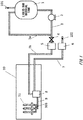
- Fig. 1 shows an example of a supply flow for supplying raw material and the like to a porous glass preform manufacturing apparatus according to the present invention.
- An organic silicon compound (raw material) 101 in a liquid state is fed from a liquid raw material tank 1.
- the method for feeding the raw material liquid 101 from the liquid raw material tank 1 may be using a liquid feeding pump 2, gas pumping, or the like, for example.
- a case is shown where the liquid feeding pump 2 is used.
- a raw material liquid pipe 3 is separated into a circulation pipe 3a that returns to the liquid raw material tank 1 and a raw material liquid supply pipe 3b that goes toward a porous glass preform manufacturing apparatus 10 via a valve 4.
- a liquid mass flow controller 5 that precisely controls the flow rate of the raw material liquid 101 is provided on the raw material liquid supply pipe 3b side.
- the raw material liquid pipe 3 preferably heats the raw material liquid 101 to a point that does not cause coagulation.
- a vaporizer 8 that vaporizes the raw material liquid 101 is arranged inside the porous glass preform manufacturing apparatus 10.
- the vaporizer 8 is also supplied with a carrier gas 102, the raw material liquid 101 is mixed with the carrier gas 102 in the vaporizer 8, and the resulting gas is supplied to a burner 11 through a raw material gas pipe 9 as a raw material gas 103.
- a gas mass flow controller 6 is provided on the carrier gas pipe 7.
- the raw material liquid 101 is provided while the liquid mass flow controller 5 changes the supply flow rate thereof from 10 g/min to 100 g/min, according to the deposition state.
- the carrier gas 102 can be an inert gas such as nitrogen, argon, or helium, or may be oxygen or a mixed gas including oxygen and an inert gas.
- the carrier gas 102 may undergo preheating according to the supply flow rate, in order to efficiently vaporize the raw material liquid 101 with the vaporizer 8.
- the carrier gas 102 By using an inert gas such as nitrogen, argon, or helium as the carrier gas 102, it is possible to safely transport the raw material. On the other hand, it is undesirable to significantly increase the ratio of the inert gas, since it is unrelated to the reaction. If an inert gas such as nitrogen is used as the carrier gas 102, the flow rate of the carrier gas 102 is preferably restricted to being less than or equal to 30 SLM.
- oxygen or a mixed gas of oxygen and inert gas is used as the carrier gas 102, complete combustion is encouraged by pre-mixing the raw material in the vaporizer.
- the supply amount of the oxygen is preferably an amount that does not cause flashback.
- the raw material liquid 101 is mixed with the carrier gas 102 in the vaporizer 8 and vaporized.
- the temperature inside the vaporizer 8 is preferably set from 150°C to 250°C.
- the raw material gas 103 including the vaporized raw material gas and the carrier gas is supplied to the burner 11 through the raw material gas pipe 9.
- the raw material gas pipe 9 is preferably heated to a temperature that is greater than a liquefaction temperature of the raw material gas, which is calculated from the partial pressure, in order to prevent reliquefaction of the raw material gas.
- the liquefaction temperature of OMCTS is 175°C when the partial pressure is 1.00 atm and is 134°C when the partial pressure is 0.30 atm.
- the heating of the raw material gas pipe 9 can be achieved using an electric heater, for example.
- the carrier gas such as oxygen is mixed with the raw material gas in the vaporizer 8, and the resulting gas is supplied to the burner 11 in a pre-mixed state. If the combustion reaction of the raw material is insufficient, a gel of impurities, impurity microparticles, or the like stick to the burner 11, carbon sticks to the soot, and defects occur in the soot. Therefore, by using oxygen as the carrier gas 102, pre-mixing the raw material and the oxygen, and supplying the resulting gas to the burner 11, it is possible to increase the reactivity of the raw material. In this way, oxygen may be used as the carrier gas 102 and this oxygen may be mixed with the raw material in the vaporizer 8, or inert gas such as nitrogen may be used as the carrier gas 102 and mixed with the raw material downstream from the vaporizer 8.
- Fig. 2 shows an example of a supply flow around the vaporizer according to the present embodiment, and shows a case where an inert gas such as nitrogen is used as the carrier gas 102, oxygen 104 is mixed with the raw material gas downstream from the vaporizer 8, and the resulting gas is supplied to the burner 11.
- an inert gas such as nitrogen
- the oxygen 104 is mixed with the raw material gas downstream from the vaporizer 8, through an oxygen pipe 13.
- the oxygen is preferably supplied in a preheated state at a temperature greater than or equal to the liquefaction temperature of the raw material gas calculated from the partial pressure, in order to prevent reliquefaction of the raw material.
- the heating of the oxygen 104 can be achieved using a small-scale heat exchanger 14 or the like.
- the carrier gas 102 may be preheated using a small-scale heat exchanger 12 or the like, according to the supply flow rate of the carrier gas 102.
- the supply flow rate of the oxygen 104 preferably has a molar ratio (standard state) for the oxygen 104 / raw material liquid 101 that is less than or equal to 8.
- a multi-nozzle burner in which a plurality of nozzles are arranged a multi-tube burner in which nozzles are arranged concentrically, or the like can be used as the burner 11.
- the gas supplied to the burner 11 is exemplified by, in addition to the raw material gas pre-mixed with the carrier gas 102 or the like, seal gas, combustible gas for combustion, oxygen gas for combustion, and the like. Hydrogen, methane, ethane, propane, or the like, for example, can be used as the combustible gas for combustion.
- Octamethylcyclotetrasiloxane hexamethyldisiloxane, hexamethylcyclotrisiloxane, decamethylcyclopentasiloxane, dodecamethylcyclohexasiloxane, trimethoxymethylsilane, tetramethoxysilane, or the like can be used as the organic silicon compound raw material.
- the boiling points of these materials are less than or equal to 300°C, and a pipe made of resin such as PTFE can be used as the pipe for the vaporized raw material gas.
- OMCTS hexamethylcyclotrisiloxane
- decamethylcyclopentasiloxane which is a pentameric cyclic siloxane
- the heating temperature of the raw material gas pipe only needs to match the boiling point of the OMCTS, and temperature management of the pipe becomes easier. Furthermore, the occurrence of polymerization products due to the reaction of the highly reactive hexamethylcyclotrisiloxane proceeding is prevented, and there is no need to excessively increase the heating temperature of the raw material gas pipe in order to match the high boiling point of the decamethylcyclopentasiloxane.
- An inert gas such as nitrogen, argon, or helium, oxygen, or a mixed gas containing oxygen and inert gas can be used as the seal gas.
- the seal gas may be provided heated, in order to prevent reliquefaction of the raw material gas.
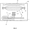
- Fig. 3 is a schematic view of the porous glass preform manufacturing apparatus used in the present invention.
- the burner 11 is moved parallel to a guide mechanism 17 using a traverse motor, not shown in the drawings.
- a starting core preform 18 is attached to a rotating mechanism 19, and rotates in a certain direction. While the burner 11 repeats the parallel motion along the longitudinal direction of the starting core preform 18, the SiO 2 microparticles generated by the raw material gas are ejected from the burner 11, and these microparticles are attached to the starting core preform 18 to form a soot deposition body 20.
- the unattached SiO 2 microparticles that did not attach to the soot deposition body 20 are expelled outside the system via an exhaust hood 21.
- the exhaust hood 21 may have localized exhaust structures or an overall exhaust structure.
- each gas pipe that supplies the raw material gas and the like to the burner 11 moves in a manner to follow the burner 11 that repeats the parallel movement.
- each pipe supplying gas to the burner 11 is preferably mobile, and by storing each gas pipe inside a mobile cable protection material 15 such as Cableveyor (Registered Trademark of TSUBAKIMOTO CHAIN CO.) or a flexible tube, for example, the gas pipes can follow the movement of the burner 11 and can move without experiencing a large amount of stress.
- the mobile cable protection material 15 is made from a flexible cylindrical member, and stores each gas cable therein.
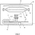
- the raw material gas pipe 9 extending from the vaporizer 8 to the burner 11 needs to be lengthened according to the length of the starting core preform 18 in the longitudinal direction and the pipe length of the raw material gas pipe 9 needs to be 2 to 3 times the movement distance of the burner in one direction, as shown in Fig. 4 .
- the length of the starting core preform 18 is 3000 mm
- the travel distance of the burner in one direction must be 3000 mm
- the pipe length of the raw material gas pipe 9 must be from 6000 mm to 9000 mm.
- the raw material gas pipe 9 In order for the raw material gas pipe 9 to prevent reliquefaction of the raw material gas, the raw material gas pipe 9 is preferably heated, using an electric heater or the like, to a temperature greater than or equal to the liquefaction temperature of the raw material gas calculated from the partial pressure. However, it is easy for temperature unevenness to occur in the pipe according to the distance from the electric heater, and it is difficult to control the temperature of the pipe to be uniform. If the vaporizer 8 is arranged secured to the front portion of the mobile cable protection material 15, the length of the raw material gas pipe 9 is increased, and therefore there are cases where the raw material component or impurity component is overheated locally to create polymers in the pipe and is condensed and liquefied at localized low-temperature portions.
- the vaporizer 8 that vaporizes the organic silicon compound in a liquid state is arranged at the rear portion of the mobile cable protection material 15, i.e. near the burner 11, and is arranged to be movable along with the burner 11 that moves due to the guide mechanism 17.
- the raw material gas pipe 9 can be set to have a certain length that is unrelated to the length of the starting core preform 18 in the longitudinal direction, and it is possible to significantly shorten the raw material gas pipe 9 leading from the vaporizer 8 to the burner 11 and to shorten the heating region of the electric heater for preventing the reliquefaction of the raw material gas.
- By making the pipe as short as possible it is possible to easily manage the temperature of the pipe and to prevent coagulation of the raw material and generation of polymers within the pipe.
- the heater is prone to breaking due to fatigue, and when a heat transfer medium is used, the pipe for the heat transfer medium is easily damaged due to fatigue. Therefore, when heating the raw material gas pipe 9, it is preferable to arrange the heating means such that excessive tensile stress and bending stress is not applied thereto, and the raw material gas pipe itself is preferably not mobile.
Landscapes
- Chemical & Material Sciences (AREA)
- Engineering & Computer Science (AREA)
- Geochemistry & Mineralogy (AREA)
- Life Sciences & Earth Sciences (AREA)
- General Chemical & Material Sciences (AREA)
- General Life Sciences & Earth Sciences (AREA)
- Chemical Kinetics & Catalysis (AREA)
- Manufacturing & Machinery (AREA)
- Materials Engineering (AREA)
- Organic Chemistry (AREA)
- Physics & Mathematics (AREA)
- Plasma & Fusion (AREA)
- Manufacture, Treatment Of Glass Fibers (AREA)
- Glass Melting And Manufacturing (AREA)
Abstract
Description
- The present invention relates to a manufacturing apparatus and a manufacturing method of a porous glass preform for optical fiber, including depositing a cladding portion on a starting core preform using an outside deposition technique (OVD).
- An optical fiber preform is manufactured by depositing SiO2 microparticles using OVD or the like on the outside of a core preform, which is manufactured using VAD or the like, and then sintering the resulting member, for example. Conventionally, silicon tetrachloride (SiCl4) is widely used as the silicon compound raw material to deposit the SiO2 microparticles on the outside of the core preform.
- The SiO2 microparticles are generated due to the flame hydrolysis reaction of the SiCl4, based on
Formula 1 shown below.
Formula 1: SiCl4 + 2H2O → SiO2 + 4HCl
- Hydrochloric acid is formed as a by-product of this reaction, and care must be taken concerning the manufacturing apparatus materials and exhaust temperature management, since this hydrochloric acid is corrosive to metals when mixed with water. Furthermore, when equipment for performing a recover processing of the hydrochloric acid from the exhaust is provided, this results in a cost increase.
- Silicon tetrachloride (SiCl4) is widely used as the silicon compound raw material, but sometimes a halogen-free organic silicon compound that does not contain Cl (chlorine) in the molecules is used as the starting material for the SiO2 microparticles. This is exemplified by octamethylcyclotetrasiloxane (OMCTS), which is an organic silicon compound having a high purity and capable of being used on an industrial scale.
- The SiO2 microparticles are generated due to the flame hydrolysis reaction of the OMCTS, based on
Formula 2 shown below.
Formula 2: [SiO(CH3)2]4 + 16O2 → 4SiO2 + 8CO2 + 12H2O
- In this way, when a halogen-free organic silicon compound, represented by OMCTS, is used as the silicon compound raw material supplied to a burner, hydrochloric acid is not generated. Therefore, the degree of freedom for the manufacturing apparatus materials and for handling the exhaust gas is increased. Furthermore, there is no need to provide equipment for performing recover processing of hydrochloric acid, and therefore it is expected that the cost will be kept down.
- When the organic silicon compound raw material, represented by OMCTS, is supplied to the burner in a liquid state, the OMCTS is vaporized and combusted irregularly by the burner, and therefore the ejection amount of the SiO2 microparticles becomes unstable, and the flame temperature changes to cause instability in the deposition amount of the SiO2 microparticles and the density of the deposition body.
- On the other hand, when the organic silicon compound raw material that has been vaporized is supplied to the burner, there are cases where this raw material reliquefies inside the pipe leading to the burner. There is a method of heating the raw material gas pipe in order to prevent reliquefaction before the gas reaches the burner, but in this case, the burner moves back and forth along the longitudinal direction of the starting member onto which the SiO2 microparticles are deposited, and therefore the raw material gas pipe must be made longer according to the length of the starting member, and there are cases where heating unevenness occurs in the pipe so that the raw material gas reliquifies locally at low-temperature portions or raw material polymers are generated locally at high-temperature portions to block the pipe.
- It is an objective of the present invention to provide a manufacturing apparatus and a manufacturing method of a porous glass preform for optical fiber, that are capable of using an organic silicon compound raw material in a liquid state as the silicon compound raw material, preventing localized reliquefaction due to uneven heating in the pipe leading to the burner and blockage of the pipe caused by localized polymer generation due to uneven heating, and performing stable deposition of the SiO2 microparticles onto the starting member.
- The manufacturing method of a porous glass preform for optical fiber according to the present invention solves the above problem, and is a manufacturing method of a porous glass preform for optical fiber by depositing glass microparticles on a starting member, comprising supplying a vaporizer with organic silicon compound raw material in a liquid state and a carrier gas; in the vaporizer, mixing together and vaporizing the organic silicon compound raw material in a liquid state and the carrier gas to convert the organic silicon compound raw material and the carrier gas into a raw material mixed gas; supplying a burner with the raw material mixed gas and a combustible gas, combusting the raw material mixed gas and the combustible gas in the burner, and ejecting SiO2 microparticles generated by the combustion from the burner; and depositing the SiO2 microparticles ejected from the burner by repeatedly moving the vaporizer and the burner together, in a synchronized manner, parallel to the starting member in a longitudinal direction thereof.
- It is preferable that the organic silicon compound raw material is octamethylcyclotetrasiloxane (OMCTS) with a purity greater than or equal to 99% by mass. An inert gas such as nitrogen, argon, or helium may be used as the carrier gas in the raw material mixed gas, and oxygen may also be mixed into the raw material mixed gas supplied to the burner. Oxygen or a mixed gas including oxygen and an inert gas may be used as the carrier gas.
- A manufacturing apparatus for manufacturing a porous glass preform for optical fiber according to the present invention is a manufacturing apparatus for manufacturing a porous glass preform, comprising a burner that deposits SiO2 microparticles on a starting member while moving parallel thereto along a longitudinal direction of the starting member; a vaporizer that converts organic silicon compound raw material from a liquid state into a gaseous state, and supplies the converted gas to the burner; and a raw material liquid pipe that supplies the organic silicon compound raw material to the vaporizer, wherein the vaporizer and the burner are arranged in a manner to be movable together. It is preferable that the raw material liquid pipe is mobile in a manner to move following the burner.
- According to the present invention, in particular, by moving the burner and the vaporizer, which vaporizes the organic silicon compound raw material, is a synchronized and integrated manner, the raw material is stably supplied to the burner in a gaseous state, and the SiO2 microparticle ejection amount and flame temperature are stabilized. Furthermore, it is possible to achieve extremely beneficial effects such as being able to give the raw material gas pipe leading from the vaporizer to the burner a constant length that is unrelated to the region in which the burner moves, being able to shorten the raw material gas pipe relative to the length of the starting member in the longitudinal direction and making it easy to uniformly heat the raw material gas pipe.
-
-
Fig. 1 shows an example of the supply flow for supplying raw material gas and the like to a porous glass preform manufacturing apparatus according to an embodiment of the present invention. -
Fig. 2 shows an example of a supply flow around the vaporizer that mixes the oxygen with the raw material gas downstream from the vaporizer, according to an embodiment of the present invention. -
Fig. 3 is a schematic view of the porous glass preform manufacturing apparatus according to an embodiment of the present invention. -
Fig. 4 is a schematic view of an installation position of a vaporizer according to a comparative example. -
Fig. 5 is a schematic view of the installation position of the vaporizer according to an embodiment of the present invention. - Hereinafter, some embodiments of the present invention will be described. The embodiments do not limit the invention according to the claims, and all the combinations of the features described in the embodiments are not necessarily essential to means provided by aspects of the invention.
-
Fig. 1 shows an example of a supply flow for supplying raw material and the like to a porous glass preform manufacturing apparatus according to the present invention. - An organic silicon compound (raw material) 101 in a liquid state is fed from a liquid
raw material tank 1. The method for feeding theraw material liquid 101 from the liquidraw material tank 1 may be using aliquid feeding pump 2, gas pumping, or the like, for example. InFig. 1 , a case is shown where theliquid feeding pump 2 is used. A raw materialliquid pipe 3 is separated into a circulation pipe 3a that returns to the liquidraw material tank 1 and a raw materialliquid supply pipe 3b that goes toward a porous glasspreform manufacturing apparatus 10 via avalve 4. A liquidmass flow controller 5 that precisely controls the flow rate of theraw material liquid 101 is provided on the raw materialliquid supply pipe 3b side. - The raw material
liquid pipe 3 preferably heats theraw material liquid 101 to a point that does not cause coagulation. Avaporizer 8 that vaporizes theraw material liquid 101 is arranged inside the porous glasspreform manufacturing apparatus 10. Thevaporizer 8 is also supplied with acarrier gas 102, theraw material liquid 101 is mixed with thecarrier gas 102 in thevaporizer 8, and the resulting gas is supplied to aburner 11 through a rawmaterial gas pipe 9 as araw material gas 103. A gasmass flow controller 6 is provided on thecarrier gas pipe 7. - The
raw material liquid 101 is provided while the liquidmass flow controller 5 changes the supply flow rate thereof from 10 g/min to 100 g/min, according to the deposition state. - The
carrier gas 102 can be an inert gas such as nitrogen, argon, or helium, or may be oxygen or a mixed gas including oxygen and an inert gas. Thecarrier gas 102 may undergo preheating according to the supply flow rate, in order to efficiently vaporize theraw material liquid 101 with thevaporizer 8. - By using an inert gas such as nitrogen, argon, or helium as the
carrier gas 102, it is possible to safely transport the raw material. On the other hand, it is undesirable to significantly increase the ratio of the inert gas, since it is unrelated to the reaction. If an inert gas such as nitrogen is used as thecarrier gas 102, the flow rate of thecarrier gas 102 is preferably restricted to being less than or equal to 30 SLM. - If oxygen or a mixed gas of oxygen and inert gas is used as the
carrier gas 102, complete combustion is encouraged by pre-mixing the raw material in the vaporizer. - The supply amount of the oxygen is preferably an amount that does not cause flashback.
- The
raw material liquid 101 is mixed with thecarrier gas 102 in thevaporizer 8 and vaporized. If OMCTS is used as the organic silicon compound raw material, from the viewpoint of efficiently vaporizing theraw material liquid 101 and preventing polymerization of the raw material, the temperature inside thevaporizer 8 is preferably set from 150°C to 250°C. Theraw material gas 103 including the vaporized raw material gas and the carrier gas is supplied to theburner 11 through the rawmaterial gas pipe 9. The rawmaterial gas pipe 9 is preferably heated to a temperature that is greater than a liquefaction temperature of the raw material gas, which is calculated from the partial pressure, in order to prevent reliquefaction of the raw material gas. Specifically, the liquefaction temperature of OMCTS is 175°C when the partial pressure is 1.00 atm and is 134°C when the partial pressure is 0.30 atm. The heating of the rawmaterial gas pipe 9 can be achieved using an electric heater, for example. - In order to encourage complete combustion of the raw material, as described above, the carrier gas such as oxygen is mixed with the raw material gas in the
vaporizer 8, and the resulting gas is supplied to theburner 11 in a pre-mixed state. If the combustion reaction of the raw material is insufficient, a gel of impurities, impurity microparticles, or the like stick to theburner 11, carbon sticks to the soot, and defects occur in the soot. Therefore, by using oxygen as thecarrier gas 102, pre-mixing the raw material and the oxygen, and supplying the resulting gas to theburner 11, it is possible to increase the reactivity of the raw material. In this way, oxygen may be used as thecarrier gas 102 and this oxygen may be mixed with the raw material in thevaporizer 8, or inert gas such as nitrogen may be used as thecarrier gas 102 and mixed with the raw material downstream from thevaporizer 8. -
Fig. 2 shows an example of a supply flow around the vaporizer according to the present embodiment, and shows a case where an inert gas such as nitrogen is used as thecarrier gas 102,oxygen 104 is mixed with the raw material gas downstream from thevaporizer 8, and the resulting gas is supplied to theburner 11. - The
oxygen 104 is mixed with the raw material gas downstream from thevaporizer 8, through anoxygen pipe 13. The oxygen is preferably supplied in a preheated state at a temperature greater than or equal to the liquefaction temperature of the raw material gas calculated from the partial pressure, in order to prevent reliquefaction of the raw material. The heating of theoxygen 104 can be achieved using a small-scale heat exchanger 14 or the like. In order to efficiently vaporize theraw material liquid 101 in thevaporizer 8, thecarrier gas 102 may be preheated using a small-scale heat exchanger 12 or the like, according to the supply flow rate of thecarrier gas 102. The supply flow rate of theoxygen 104 preferably has a molar ratio (standard state) for theoxygen 104 /raw material liquid 101 that is less than or equal to 8. - With the manufacturing method of the porous glass preform for optical fiber according to the present invention, a multi-nozzle burner in which a plurality of nozzles are arranged, a multi-tube burner in which nozzles are arranged concentrically, or the like can be used as the
burner 11. - The gas supplied to the
burner 11 is exemplified by, in addition to the raw material gas pre-mixed with thecarrier gas 102 or the like, seal gas, combustible gas for combustion, oxygen gas for combustion, and the like. Hydrogen, methane, ethane, propane, or the like, for example, can be used as the combustible gas for combustion. - Octamethylcyclotetrasiloxane (OMCTS), hexamethyldisiloxane, hexamethylcyclotrisiloxane, decamethylcyclopentasiloxane, dodecamethylcyclohexasiloxane, trimethoxymethylsilane, tetramethoxysilane, or the like can be used as the organic silicon compound raw material. The boiling points of these materials are less than or equal to 300°C, and a pipe made of resin such as PTFE can be used as the pipe for the vaporized raw material gas.
- In the present invention, it is possible to use mixed raw material in which a plurality of types of organic silicon compound raw materials are mixed together, but from the viewpoint of reaction stability and ease of pipe temperature management, it is preferable to use a single type of raw material with high purity. For example, if OMCTS is used, it is referable for the purity thereof to be greater than or equal to 99% by mass. OMCTS is prone to containing hexamethylcyclotrisiloxane, which is a trimeric cyclic siloxane, and decamethylcyclopentasiloxane, which is a pentameric cyclic siloxane, as impurity components. These impurity components have different reactivities and boiling temperatures than the OMCTS. Accordingly, by increasing the purity of the OMCTS, the heating temperature of the raw material gas pipe only needs to match the boiling point of the OMCTS, and temperature management of the pipe becomes easier. Furthermore, the occurrence of polymerization products due to the reaction of the highly reactive hexamethylcyclotrisiloxane proceeding is prevented, and there is no need to excessively increase the heating temperature of the raw material gas pipe in order to match the high boiling point of the decamethylcyclopentasiloxane.
- An inert gas such as nitrogen, argon, or helium, oxygen, or a mixed gas containing oxygen and inert gas can be used as the seal gas. The seal gas may be provided heated, in order to prevent reliquefaction of the raw material gas.
-
Fig. 3 is a schematic view of the porous glass preform manufacturing apparatus used in the present invention. - The
burner 11 is moved parallel to aguide mechanism 17 using a traverse motor, not shown in the drawings. A startingcore preform 18 is attached to arotating mechanism 19, and rotates in a certain direction. While theburner 11 repeats the parallel motion along the longitudinal direction of the startingcore preform 18, the SiO2 microparticles generated by the raw material gas are ejected from theburner 11, and these microparticles are attached to the starting core preform 18 to form asoot deposition body 20. The unattached SiO2 microparticles that did not attach to thesoot deposition body 20 are expelled outside the system via anexhaust hood 21. Theexhaust hood 21 may have localized exhaust structures or an overall exhaust structure. - Each gas pipe that supplies the raw material gas and the like to the
burner 11 moves in a manner to follow theburner 11 that repeats the parallel movement. At this time, each pipe supplying gas to theburner 11 is preferably mobile, and by storing each gas pipe inside a mobilecable protection material 15 such as Cableveyor (Registered Trademark of TSUBAKIMOTO CHAIN CO.) or a flexible tube, for example, the gas pipes can follow the movement of theburner 11 and can move without experiencing a large amount of stress. The mobilecable protection material 15 is made from a flexible cylindrical member, and stores each gas cable therein. - In a case where the
vaporizer 8 that vaporizes the organic silicon compound with such a configuration is arranged secured to a front portion of the mobilecable protection material 15, the rawmaterial gas pipe 9 extending from thevaporizer 8 to theburner 11 needs to be lengthened according to the length of the startingcore preform 18 in the longitudinal direction and the pipe length of the rawmaterial gas pipe 9 needs to be 2 to 3 times the movement distance of the burner in one direction, as shown inFig. 4 . For example, if the length of the startingcore preform 18 is 3000 mm, the travel distance of the burner in one direction must be 3000 mm, and therefore the pipe length of the rawmaterial gas pipe 9 must be from 6000 mm to 9000 mm. - In order for the raw
material gas pipe 9 to prevent reliquefaction of the raw material gas, the rawmaterial gas pipe 9 is preferably heated, using an electric heater or the like, to a temperature greater than or equal to the liquefaction temperature of the raw material gas calculated from the partial pressure. However, it is easy for temperature unevenness to occur in the pipe according to the distance from the electric heater, and it is difficult to control the temperature of the pipe to be uniform. If thevaporizer 8 is arranged secured to the front portion of the mobilecable protection material 15, the length of the rawmaterial gas pipe 9 is increased, and therefore there are cases where the raw material component or impurity component is overheated locally to create polymers in the pipe and is condensed and liquefied at localized low-temperature portions. - Therefore, in the present embodiment, as shown in
Fig. 5 , thevaporizer 8 that vaporizes the organic silicon compound in a liquid state is arranged at the rear portion of the mobilecable protection material 15, i.e. near theburner 11, and is arranged to be movable along with theburner 11 that moves due to theguide mechanism 17. - In this way, the raw
material gas pipe 9 can be set to have a certain length that is unrelated to the length of the startingcore preform 18 in the longitudinal direction, and it is possible to significantly shorten the rawmaterial gas pipe 9 leading from thevaporizer 8 to theburner 11 and to shorten the heating region of the electric heater for preventing the reliquefaction of the raw material gas. As a result, it is possible to restrict the generation of polymerization products within the rawmaterial gas pipe 9, and to heat the rawmaterial gas pipe 9 using the heater without applying excessive tensile stress or bending stress. By making the pipe as short as possible, it is possible to easily manage the temperature of the pipe and to prevent coagulation of the raw material and generation of polymers within the pipe. - When the raw
material gas pipe 9 heated by the heater is stored inside the mobilecable protection material 15 and the electric heater for heating the pipe is used, the heater is prone to breaking due to fatigue, and when a heat transfer medium is used, the pipe for the heat transfer medium is easily damaged due to fatigue. Therefore, when heating the rawmaterial gas pipe 9, it is preferable to arrange the heating means such that excessive tensile stress and bending stress is not applied thereto, and the raw material gas pipe itself is preferably not mobile. - 101 ... organic silicon compound (raw material); 102 ... carrier gas; 103 ... mixed gas of raw material gas and carrier gas; 104 ... oxygen; 1 ... liquid raw material tank; 2 ... liquid feeding pump; 3 ... raw material liquid pipe; 3a ... circulation pipe; 3b ... raw material liquid supply pipe; 4 ... valve; 5 ... liquid mass flow controller; 6 ... gas mass flow controller; 7 ... carrier gas pipe; 8 ... vaporizer; 9 ... raw material gas pipe; 10 ... porous glass preform manufacturing apparatus; 11 ... burner; 12 ... small-scale heat exchanger; 13 ... oxygen pipe; 14 ... heat exchanger; 15 ... mobile cable protection material; 17 ... guide mechanism; 18 ... starting core preform; 19 ... rotating mechanism; 20 ... soot deposition body; 21 ... exhaust hood
Claims (11)
- A manufacturing method of a porous glass preform for optical fiber by depositing glass microparticles on a starting member, the manufacturing method comprising:supplying a vaporizer with organic silicon compound raw material in a liquid state and a carrier gas;in the vaporizer, mixing together and vaporizing the organic silicon compound raw material in a liquid state and the carrier gas to convert the organic silicon compound raw material and the carrier gas into a raw material mixed gas;supplying a burner with the raw material mixed gas and a combustible gas, combusting the raw material mixed gas and the combustible gas in the burner, and ejecting SiO2 microparticles generated by the combustion from the burner; anddepositing the SiO2 microparticles ejected from the burner on the starting member by repeatedly moving the vaporizer and the burner together, in a synchronized manner, parallel to the starting member in a longitudinal direction thereof.
- The manufacturing method of a porous glass preform for optical fiber according to Claim 1, wherein
the organic silicon compound raw material is octamethylcyclotetrasiloxane (OMCTS) with a purity greater than or equal to 99% by mass. - The manufacturing method of a porous glass preform for optical fiber according to Claim 1 or 2, wherein
an inert gas such as nitrogen, argon, or helium is used as the carrier gas in the raw material mixed gas. - The manufacturing method of a porous glass preform for optical fiber according to Claim 3, wherein
oxygen is also mixed into the raw material mixed gas to be supplied to the burner. - The manufacturing method of a porous glass preform for optical fiber according to any one of Claims 1 to 4, wherein
oxygen or a mixed gas including oxygen and an inert gas is used as the carrier gas. - The manufacturing method of a porous glass preform for optical fiber according to any one of Claims 1 to 5, wherein
a raw material gas pipe that supplies raw material gas from the vaporizer to the burner is stored in a flexible mobile cable protection material, and
the depositing includes moving the burner while guiding the burner with a guide mechanism. - The manufacturing method of a porous glass preform for optical fiber according to any one of Claims 1 to 6, further comprising:
heating a raw material gas pipe that supplies raw material gas from the vaporizer to the burner. - A manufacturing apparatus for manufacturing a porous glass preform for optical fiber, comprising:a burner that deposits SiO2 microparticles on a starting member while moving parallel thereto along a longitudinal direction of the starting member;a vaporizer that converts organic silicon compound raw material from a liquid state into a gaseous state, and supplies the converted gas to the burner; anda raw material liquid pipe that supplies the organic silicon compound raw material to the vaporizer, whereinthe vaporizer and the burner are arranged in a manner to be movable together.
- The manufacturing apparatus for manufacturing a porous glass preform for optical fiber according to Claim 8, wherein
the raw material liquid pipe is mobile in a manner to move following the burner. - The manufacturing apparatus for manufacturing a porous glass preform for optical fiber according to Claim 8 or 9, further comprising:a guide mechanism that guides the movement of the burner;a raw material gas pipe that supplies a raw material gas from the vaporizer to the burner; anda mobile cable protection material that is flexible and stores the raw material gas pipe.
- The manufacturing apparatus for manufacturing a porous glass preform for optical fiber according to any one of Claims 8 to 10, further comprising:a raw material gas pipe that supplies a raw material gas from the vaporizer to the burner; anda heater that heats the raw material gas pipe.
Priority Applications (1)
| Application Number | Priority Date | Filing Date | Title |
|---|---|---|---|
| EP21159623.4A EP3865462A1 (en) | 2018-04-02 | 2019-03-29 | Apparatus and method for manufacturing porous glass preform for optical fiber |
Applications Claiming Priority (1)
| Application Number | Priority Date | Filing Date | Title |
|---|---|---|---|
| JP2018070632A JP6793676B2 (en) | 2018-04-02 | 2018-04-02 | Manufacturing equipment and manufacturing method for porous glass base material for optical fibers |
Related Child Applications (2)
| Application Number | Title | Priority Date | Filing Date |
|---|---|---|---|
| EP21159623.4A Division-Into EP3865462A1 (en) | 2018-04-02 | 2019-03-29 | Apparatus and method for manufacturing porous glass preform for optical fiber |
| EP21159623.4A Division EP3865462A1 (en) | 2018-04-02 | 2019-03-29 | Apparatus and method for manufacturing porous glass preform for optical fiber |
Publications (2)
| Publication Number | Publication Date |
|---|---|
| EP3549921A1 true EP3549921A1 (en) | 2019-10-09 |
| EP3549921B1 EP3549921B1 (en) | 2021-05-05 |
Family
ID=66041352
Family Applications (2)
| Application Number | Title | Priority Date | Filing Date |
|---|---|---|---|
| EP21159623.4A Withdrawn EP3865462A1 (en) | 2018-04-02 | 2019-03-29 | Apparatus and method for manufacturing porous glass preform for optical fiber |
| EP19166406.9A Active EP3549921B1 (en) | 2018-04-02 | 2019-03-29 | Apparatus and method for manufacturing porous glass preform for optical fiber |
Family Applications Before (1)
| Application Number | Title | Priority Date | Filing Date |
|---|---|---|---|
| EP21159623.4A Withdrawn EP3865462A1 (en) | 2018-04-02 | 2019-03-29 | Apparatus and method for manufacturing porous glass preform for optical fiber |
Country Status (4)
| Country | Link |
|---|---|
| US (2) | US11155488B2 (en) |
| EP (2) | EP3865462A1 (en) |
| JP (1) | JP6793676B2 (en) |
| CN (1) | CN110342807A (en) |
Cited By (2)
| Publication number | Priority date | Publication date | Assignee | Title |
|---|---|---|---|---|
| EP4015466A1 (en) * | 2020-12-16 | 2022-06-22 | Heraeus Quarzglas GmbH & Co. KG | Method for the manufacture of synthetic quartz glass |
| EP4015467A1 (en) * | 2020-12-16 | 2022-06-22 | Heraeus Quarzglas GmbH & Co. KG | Method for the manufacture of synthetic quartz glass |
Families Citing this family (11)
| Publication number | Priority date | Publication date | Assignee | Title |
|---|---|---|---|---|
| JP7276335B2 (en) * | 2018-06-15 | 2023-05-18 | 住友電気工業株式会社 | Manufacturing method of glass fine particle deposit |
| JP7463967B2 (en) * | 2018-12-04 | 2024-04-09 | 住友電気工業株式会社 | Apparatus and method for manufacturing soot glass deposit |
| JP7171639B2 (en) * | 2020-03-13 | 2022-11-15 | 信越化学工業株式会社 | Manufacturing method of porous glass base material for optical fiber |
| JP7449842B2 (en) * | 2020-11-02 | 2024-03-14 | 信越化学工業株式会社 | Manufacturing method and manufacturing device for porous glass base material |
| JP7428632B2 (en) | 2020-12-14 | 2024-02-06 | 信越化学工業株式会社 | Manufacturing method and manufacturing device for porous glass base material |
| EP4015468A1 (en) | 2020-12-16 | 2022-06-22 | Heraeus Quarzglas GmbH & Co. KG | Method for the manufacture of synthetic quartz glass |
| JP7508390B2 (en) * | 2021-02-26 | 2024-07-01 | 古河電気工業株式会社 | Optical fiber preform manufacturing apparatus and method |
| JP2023141265A (en) * | 2022-03-23 | 2023-10-05 | 住友電気工業株式会社 | glass processing equipment |
| JP7855502B2 (en) | 2022-12-15 | 2026-05-08 | 信越化学工業株式会社 | Porous glass substrate manufacturing system and glass substrate manufacturing method |
| JP2025090479A (en) * | 2023-12-05 | 2025-06-17 | 信越化学工業株式会社 | Apparatus and method for manufacturing a porous glass preform for optical fiber |
| CN117985934B (en) * | 2023-12-21 | 2026-03-10 | 华能(泰安)光电科技有限公司 | Optical fiber perform prepares cladding deposition device |
Citations (2)
| Publication number | Priority date | Publication date | Assignee | Title |
|---|---|---|---|---|
| JPS57188424A (en) * | 1981-05-15 | 1982-11-19 | Nippon Telegr & Teleph Corp <Ntt> | Manufacture of base material for glass fiber |
| US20140349830A1 (en) * | 2011-12-15 | 2014-11-27 | Heraeus Quarzglas Gmbh & Co. Kg | Method for producing synthetic quartz glass and quartz glass for use as cladding material of an optical fiber |
Family Cites Families (30)
| Publication number | Priority date | Publication date | Assignee | Title |
|---|---|---|---|---|
| US4314837A (en) | 1979-03-01 | 1982-02-09 | Corning Glass Works | Reactant delivery system method |
| JPS63134531A (en) * | 1986-11-21 | 1988-06-07 | Furukawa Electric Co Ltd:The | Device for synthesizing glass fine particle |
| JPS63285131A (en) * | 1987-05-16 | 1988-11-22 | Fujikura Ltd | Device for producing optical fiber preform |
| JPH02217330A (en) * | 1989-02-17 | 1990-08-30 | Fujikura Ltd | Method and apparatus for feeding silicon tetrachloride raw material gas |
| US6312656B1 (en) * | 1995-12-19 | 2001-11-06 | Corning Incorporated | Method for forming silica by combustion of liquid reactants using oxygen |
| WO1999002459A1 (en) * | 1997-07-08 | 1999-01-21 | Corning Incorporated | Germanium chloride and siloxane feedstock for forming silica glass and method |
| JP3794664B2 (en) | 1998-07-29 | 2006-07-05 | 信越化学工業株式会社 | Synthetic quartz glass member, manufacturing method thereof, and optical component for excimer laser |
| JP2000159532A (en) * | 1998-11-19 | 2000-06-13 | Furukawa Electric Co Ltd:The | Equipment for manufacturing porous glass preform for optical fiber |
| US8516855B2 (en) * | 2001-04-27 | 2013-08-27 | Prysmian Cavi E Sistemi Energia S.R.L. | Method for producing an optical fiber preform |
| JP2003073131A (en) * | 2001-06-19 | 2003-03-12 | Sumitomo Electric Ind Ltd | Method for producing glass particulate deposit |
| JP3968451B2 (en) * | 2002-07-08 | 2007-08-29 | 昭和電線ケーブルシステム株式会社 | Optical fiber preform manufacturing method and manufacturing apparatus thereof |
| JP2004161555A (en) * | 2002-11-14 | 2004-06-10 | Sumitomo Electric Ind Ltd | Method for supplying glass forming gas, method for producing glass fine particle deposit, and respective apparatuses |
| KR100521957B1 (en) * | 2003-07-11 | 2005-10-14 | 엘에스전선 주식회사 | Outside Vapor Deposition Apparatus For Manufacturing Optical Fiber Preform and Method For Manufacturing Optical Fiber Preform Using The Same |
| JP4358088B2 (en) * | 2004-01-14 | 2009-11-04 | 株式会社フジクラ | Production equipment for porous glass preform for optical fiber |
| WO2007054961A2 (en) * | 2005-09-05 | 2007-05-18 | Sterlite Optical Technologies Ltd. | Optical fiber preform having large size soot porous body and its method of preparation |
| WO2007046468A1 (en) * | 2005-10-19 | 2007-04-26 | Kenji Okayasu | Combustion apparatus employing small evaporator |
| KR100727362B1 (en) * | 2007-01-05 | 2007-06-13 | 주식회사 코닥트 | Cable Bear Reduces Noise and Dust |
| JP5399798B2 (en) * | 2008-07-18 | 2014-01-29 | 信越化学工業株式会社 | Optical fiber preform manufacturing method and optical fiber preform manufacturing apparatus |
| DE102009010497A1 (en) * | 2008-12-19 | 2010-08-05 | J-Fiber Gmbh | Multi-nozzle tubular plasma deposition burner for the production of preforms as semi-finished products for optical fibers |
| JP5793834B2 (en) * | 2010-07-15 | 2015-10-14 | 住友電気工業株式会社 | GLASS PARTICLE DEPOSITING METHOD AND GLASS |
| US9630872B2 (en) * | 2011-09-29 | 2017-04-25 | Sumitomo Electric Industries, Ltd. | Method for manufacturing glass-fine-particle-deposited body and method for manufacturing glass base material |
| DE102011119339A1 (en) * | 2011-11-25 | 2013-05-29 | Heraeus Quarzglas Gmbh & Co. Kg | Sputtering process for the production of synthetic quartz glass |
| DE102011119374A1 (en) * | 2011-11-25 | 2013-05-29 | Heraeus Quarzglas Gmbh & Co. Kg | Process for the production of synthetic quartz glass |
| CN104125933B (en) * | 2012-12-28 | 2017-07-28 | 住友电气工业株式会社 | Method for producing glass particle deposit and method for producing glass base material |
| DE102013209673B3 (en) * | 2013-05-24 | 2014-05-22 | Heraeus Quarzglas Gmbh & Co. Kg | Process and evaporator for the production of synthetic quartz glass |
| CN103755135B (en) * | 2013-12-25 | 2016-08-17 | 中天科技精密材料有限公司 | A kind of preform surrounding layer high efficiency preparation method and equipment thereof |
| JP6284275B2 (en) * | 2014-12-22 | 2018-02-28 | 信越化学工業株式会社 | Optical fiber preform manufacturing equipment |
| JP2017036172A (en) * | 2015-08-07 | 2017-02-16 | 株式会社フジクラ | Manufacturing method for optical fiber preform |
| US11577982B2 (en) * | 2015-10-07 | 2023-02-14 | Corning Incorporated | Method to prevent cracks in optical fiber preforms |
| CN106082633B (en) * | 2016-08-22 | 2019-07-23 | 长飞光纤光缆股份有限公司 | It is a kind of for depositing the burner and deposition method of preform |
-
2018
- 2018-04-02 JP JP2018070632A patent/JP6793676B2/en active Active
-
2019
- 2019-03-20 CN CN201910213190.8A patent/CN110342807A/en active Pending
- 2019-03-29 EP EP21159623.4A patent/EP3865462A1/en not_active Withdrawn
- 2019-03-29 EP EP19166406.9A patent/EP3549921B1/en active Active
- 2019-04-01 US US16/371,118 patent/US11155488B2/en active Active
-
2021
- 2021-09-01 US US17/463,566 patent/US20210395131A1/en not_active Abandoned
Patent Citations (2)
| Publication number | Priority date | Publication date | Assignee | Title |
|---|---|---|---|---|
| JPS57188424A (en) * | 1981-05-15 | 1982-11-19 | Nippon Telegr & Teleph Corp <Ntt> | Manufacture of base material for glass fiber |
| US20140349830A1 (en) * | 2011-12-15 | 2014-11-27 | Heraeus Quarzglas Gmbh & Co. Kg | Method for producing synthetic quartz glass and quartz glass for use as cladding material of an optical fiber |
Cited By (4)
| Publication number | Priority date | Publication date | Assignee | Title |
|---|---|---|---|---|
| EP4015466A1 (en) * | 2020-12-16 | 2022-06-22 | Heraeus Quarzglas GmbH & Co. KG | Method for the manufacture of synthetic quartz glass |
| EP4015467A1 (en) * | 2020-12-16 | 2022-06-22 | Heraeus Quarzglas GmbH & Co. KG | Method for the manufacture of synthetic quartz glass |
| EP4015471A1 (en) | 2020-12-16 | 2022-06-22 | Heraeus Quarzglas GmbH & Co. KG | Method for the manufacture of synthetic quartz glass |
| EP4015470A1 (en) | 2020-12-16 | 2022-06-22 | Heraeus Quarzglas GmbH & Co. KG | Process for the preparation of synthetic quartz glass |
Also Published As
| Publication number | Publication date |
|---|---|
| EP3549921B1 (en) | 2021-05-05 |
| US20210395131A1 (en) | 2021-12-23 |
| JP2019182668A (en) | 2019-10-24 |
| US11155488B2 (en) | 2021-10-26 |
| JP6793676B2 (en) | 2020-12-02 |
| CN110342807A (en) | 2019-10-18 |
| EP3865462A1 (en) | 2021-08-18 |
| US20190300419A1 (en) | 2019-10-03 |
Similar Documents
| Publication | Publication Date | Title |
|---|---|---|
| US11155488B2 (en) | Apparatus and method for manufacturing porous glass preform for optical fiber | |
| KR100473827B1 (en) | Method and apparatus for forming fused silica by combustion of liquid reactants | |
| AU741475B2 (en) | Method and apparatus for forming silica by combustion of liquidreactants using a heater | |
| US10167543B2 (en) | Method for manufacturing optical fiber preform | |
| CN104163569A (en) | Method for manufacturing soot glass deposit body and burner for manufacturing soot glass deposit body | |
| JP2020200225A (en) | Apparatus and method for manufacturing optical fiber porous glass preform | |
| US12509387B2 (en) | Apparatus and method for producing porous glass preform | |
| US12371364B2 (en) | Porous glass base material manufacturing apparatus, method for manufacturing porous glass base material, and method for manufacturing glass base material for optical fiber | |
| KR102780078B1 (en) | Manufacturing method of porous glass base material for optical fiber | |
| JP7194301B2 (en) | Manufacturing method of porous glass base material for optical fiber | |
| JP7449842B2 (en) | Manufacturing method and manufacturing device for porous glass base material |
Legal Events
| Date | Code | Title | Description |
|---|---|---|---|
| PUAI | Public reference made under article 153(3) epc to a published international application that has entered the european phase |
Free format text: ORIGINAL CODE: 0009012 |
|
| STAA | Information on the status of an ep patent application or granted ep patent |
Free format text: STATUS: THE APPLICATION HAS BEEN PUBLISHED |
|
| AK | Designated contracting states |
Kind code of ref document: A1 Designated state(s): AL AT BE BG CH CY CZ DE DK EE ES FI FR GB GR HR HU IE IS IT LI LT LU LV MC MK MT NL NO PL PT RO RS SE SI SK SM TR |
|
| AX | Request for extension of the european patent |
Extension state: BA ME |
|
| STAA | Information on the status of an ep patent application or granted ep patent |
Free format text: STATUS: REQUEST FOR EXAMINATION WAS MADE |
|
| 17P | Request for examination filed |
Effective date: 20200318 |
|
| RBV | Designated contracting states (corrected) |
Designated state(s): AL AT BE BG CH CY CZ DE DK EE ES FI FR GB GR HR HU IE IS IT LI LT LU LV MC MK MT NL NO PL PT RO RS SE SI SK SM TR |
|
| GRAP | Despatch of communication of intention to grant a patent |
Free format text: ORIGINAL CODE: EPIDOSNIGR1 |
|
| STAA | Information on the status of an ep patent application or granted ep patent |
Free format text: STATUS: GRANT OF PATENT IS INTENDED |
|
| INTG | Intention to grant announced |
Effective date: 20201104 |
|
| GRAS | Grant fee paid |
Free format text: ORIGINAL CODE: EPIDOSNIGR3 |
|
| GRAA | (expected) grant |
Free format text: ORIGINAL CODE: 0009210 |
|
| STAA | Information on the status of an ep patent application or granted ep patent |
Free format text: STATUS: THE PATENT HAS BEEN GRANTED |
|
| AK | Designated contracting states |
Kind code of ref document: B1 Designated state(s): AL AT BE BG CH CY CZ DE DK EE ES FI FR GB GR HR HU IE IS IT LI LT LU LV MC MK MT NL NO PL PT RO RS SE SI SK SM TR |
|
| REG | Reference to a national code |
Ref country code: GB Ref legal event code: FG4D |
|
| REG | Reference to a national code |
Ref country code: CH Ref legal event code: EP |
|
| REG | Reference to a national code |
Ref country code: AT Ref legal event code: REF Ref document number: 1389631 Country of ref document: AT Kind code of ref document: T Effective date: 20210515 |
|
| REG | Reference to a national code |
Ref country code: IE Ref legal event code: FG4D |
|
| REG | Reference to a national code |
Ref country code: DE Ref legal event code: R096 Ref document number: 602019004376 Country of ref document: DE |
|
| REG | Reference to a national code |
Ref country code: LT Ref legal event code: MG9D |
|
| REG | Reference to a national code |
Ref country code: AT Ref legal event code: MK05 Ref document number: 1389631 Country of ref document: AT Kind code of ref document: T Effective date: 20210505 |
|
| PG25 | Lapsed in a contracting state [announced via postgrant information from national office to epo] |
Ref country code: FI Free format text: LAPSE BECAUSE OF FAILURE TO SUBMIT A TRANSLATION OF THE DESCRIPTION OR TO PAY THE FEE WITHIN THE PRESCRIBED TIME-LIMIT Effective date: 20210505 Ref country code: HR Free format text: LAPSE BECAUSE OF FAILURE TO SUBMIT A TRANSLATION OF THE DESCRIPTION OR TO PAY THE FEE WITHIN THE PRESCRIBED TIME-LIMIT Effective date: 20210505 Ref country code: LT Free format text: LAPSE BECAUSE OF FAILURE TO SUBMIT A TRANSLATION OF THE DESCRIPTION OR TO PAY THE FEE WITHIN THE PRESCRIBED TIME-LIMIT Effective date: 20210505 Ref country code: BG Free format text: LAPSE BECAUSE OF FAILURE TO SUBMIT A TRANSLATION OF THE DESCRIPTION OR TO PAY THE FEE WITHIN THE PRESCRIBED TIME-LIMIT Effective date: 20210805 Ref country code: AT Free format text: LAPSE BECAUSE OF FAILURE TO SUBMIT A TRANSLATION OF THE DESCRIPTION OR TO PAY THE FEE WITHIN THE PRESCRIBED TIME-LIMIT Effective date: 20210505 |
|
| PG25 | Lapsed in a contracting state [announced via postgrant information from national office to epo] |
Ref country code: GR Free format text: LAPSE BECAUSE OF FAILURE TO SUBMIT A TRANSLATION OF THE DESCRIPTION OR TO PAY THE FEE WITHIN THE PRESCRIBED TIME-LIMIT Effective date: 20210806 Ref country code: IS Free format text: LAPSE BECAUSE OF FAILURE TO SUBMIT A TRANSLATION OF THE DESCRIPTION OR TO PAY THE FEE WITHIN THE PRESCRIBED TIME-LIMIT Effective date: 20210905 Ref country code: LV Free format text: LAPSE BECAUSE OF FAILURE TO SUBMIT A TRANSLATION OF THE DESCRIPTION OR TO PAY THE FEE WITHIN THE PRESCRIBED TIME-LIMIT Effective date: 20210505 Ref country code: PL Free format text: LAPSE BECAUSE OF FAILURE TO SUBMIT A TRANSLATION OF THE DESCRIPTION OR TO PAY THE FEE WITHIN THE PRESCRIBED TIME-LIMIT Effective date: 20210505 Ref country code: NO Free format text: LAPSE BECAUSE OF FAILURE TO SUBMIT A TRANSLATION OF THE DESCRIPTION OR TO PAY THE FEE WITHIN THE PRESCRIBED TIME-LIMIT Effective date: 20210805 Ref country code: SE Free format text: LAPSE BECAUSE OF FAILURE TO SUBMIT A TRANSLATION OF THE DESCRIPTION OR TO PAY THE FEE WITHIN THE PRESCRIBED TIME-LIMIT Effective date: 20210505 Ref country code: PT Free format text: LAPSE BECAUSE OF FAILURE TO SUBMIT A TRANSLATION OF THE DESCRIPTION OR TO PAY THE FEE WITHIN THE PRESCRIBED TIME-LIMIT Effective date: 20210906 Ref country code: RS Free format text: LAPSE BECAUSE OF FAILURE TO SUBMIT A TRANSLATION OF THE DESCRIPTION OR TO PAY THE FEE WITHIN THE PRESCRIBED TIME-LIMIT Effective date: 20210505 |
|
| REG | Reference to a national code |
Ref country code: NL Ref legal event code: MP Effective date: 20210505 |
|
| PG25 | Lapsed in a contracting state [announced via postgrant information from national office to epo] |
Ref country code: NL Free format text: LAPSE BECAUSE OF FAILURE TO SUBMIT A TRANSLATION OF THE DESCRIPTION OR TO PAY THE FEE WITHIN THE PRESCRIBED TIME-LIMIT Effective date: 20210505 |
|
| PG25 | Lapsed in a contracting state [announced via postgrant information from national office to epo] |
Ref country code: SK Free format text: LAPSE BECAUSE OF FAILURE TO SUBMIT A TRANSLATION OF THE DESCRIPTION OR TO PAY THE FEE WITHIN THE PRESCRIBED TIME-LIMIT Effective date: 20210505 Ref country code: ES Free format text: LAPSE BECAUSE OF FAILURE TO SUBMIT A TRANSLATION OF THE DESCRIPTION OR TO PAY THE FEE WITHIN THE PRESCRIBED TIME-LIMIT Effective date: 20210505 Ref country code: EE Free format text: LAPSE BECAUSE OF FAILURE TO SUBMIT A TRANSLATION OF THE DESCRIPTION OR TO PAY THE FEE WITHIN THE PRESCRIBED TIME-LIMIT Effective date: 20210505 Ref country code: SM Free format text: LAPSE BECAUSE OF FAILURE TO SUBMIT A TRANSLATION OF THE DESCRIPTION OR TO PAY THE FEE WITHIN THE PRESCRIBED TIME-LIMIT Effective date: 20210505 Ref country code: RO Free format text: LAPSE BECAUSE OF FAILURE TO SUBMIT A TRANSLATION OF THE DESCRIPTION OR TO PAY THE FEE WITHIN THE PRESCRIBED TIME-LIMIT Effective date: 20210505 Ref country code: DK Free format text: LAPSE BECAUSE OF FAILURE TO SUBMIT A TRANSLATION OF THE DESCRIPTION OR TO PAY THE FEE WITHIN THE PRESCRIBED TIME-LIMIT Effective date: 20210505 Ref country code: CZ Free format text: LAPSE BECAUSE OF FAILURE TO SUBMIT A TRANSLATION OF THE DESCRIPTION OR TO PAY THE FEE WITHIN THE PRESCRIBED TIME-LIMIT Effective date: 20210505 |
|
| REG | Reference to a national code |
Ref country code: DE Ref legal event code: R097 Ref document number: 602019004376 Country of ref document: DE |
|
| PLBE | No opposition filed within time limit |
Free format text: ORIGINAL CODE: 0009261 |
|
| STAA | Information on the status of an ep patent application or granted ep patent |
Free format text: STATUS: NO OPPOSITION FILED WITHIN TIME LIMIT |
|
| 26N | No opposition filed |
Effective date: 20220208 |
|
| PG25 | Lapsed in a contracting state [announced via postgrant information from national office to epo] |
Ref country code: IS Free format text: LAPSE BECAUSE OF FAILURE TO SUBMIT A TRANSLATION OF THE DESCRIPTION OR TO PAY THE FEE WITHIN THE PRESCRIBED TIME-LIMIT Effective date: 20210905 Ref country code: AL Free format text: LAPSE BECAUSE OF FAILURE TO SUBMIT A TRANSLATION OF THE DESCRIPTION OR TO PAY THE FEE WITHIN THE PRESCRIBED TIME-LIMIT Effective date: 20210505 |
|
| PG25 | Lapsed in a contracting state [announced via postgrant information from national office to epo] |
Ref country code: MC Free format text: LAPSE BECAUSE OF FAILURE TO SUBMIT A TRANSLATION OF THE DESCRIPTION OR TO PAY THE FEE WITHIN THE PRESCRIBED TIME-LIMIT Effective date: 20210505 |
|
| REG | Reference to a national code |
Ref country code: CH Ref legal event code: PL |
|
| REG | Reference to a national code |
Ref country code: BE Ref legal event code: MM Effective date: 20220331 |
|
| PG25 | Lapsed in a contracting state [announced via postgrant information from national office to epo] |
Ref country code: LU Free format text: LAPSE BECAUSE OF NON-PAYMENT OF DUE FEES Effective date: 20220329 Ref country code: LI Free format text: LAPSE BECAUSE OF NON-PAYMENT OF DUE FEES Effective date: 20220331 Ref country code: IE Free format text: LAPSE BECAUSE OF NON-PAYMENT OF DUE FEES Effective date: 20220329 Ref country code: FR Free format text: LAPSE BECAUSE OF NON-PAYMENT OF DUE FEES Effective date: 20220331 Ref country code: CH Free format text: LAPSE BECAUSE OF NON-PAYMENT OF DUE FEES Effective date: 20220331 |
|
| PG25 | Lapsed in a contracting state [announced via postgrant information from national office to epo] |
Ref country code: BE Free format text: LAPSE BECAUSE OF NON-PAYMENT OF DUE FEES Effective date: 20220331 |
|
| GBPC | Gb: european patent ceased through non-payment of renewal fee |
Effective date: 20230329 |
|
| PG25 | Lapsed in a contracting state [announced via postgrant information from national office to epo] |
Ref country code: GB Free format text: LAPSE BECAUSE OF NON-PAYMENT OF DUE FEES Effective date: 20230329 |
|
| PG25 | Lapsed in a contracting state [announced via postgrant information from national office to epo] |
Ref country code: GB Free format text: LAPSE BECAUSE OF NON-PAYMENT OF DUE FEES Effective date: 20230329 |
|
| PG25 | Lapsed in a contracting state [announced via postgrant information from national office to epo] |
Ref country code: MK Free format text: LAPSE BECAUSE OF FAILURE TO SUBMIT A TRANSLATION OF THE DESCRIPTION OR TO PAY THE FEE WITHIN THE PRESCRIBED TIME-LIMIT Effective date: 20210505 Ref country code: CY Free format text: LAPSE BECAUSE OF FAILURE TO SUBMIT A TRANSLATION OF THE DESCRIPTION OR TO PAY THE FEE WITHIN THE PRESCRIBED TIME-LIMIT Effective date: 20210505 |
|
| PG25 | Lapsed in a contracting state [announced via postgrant information from national office to epo] |
Ref country code: HU Free format text: LAPSE BECAUSE OF FAILURE TO SUBMIT A TRANSLATION OF THE DESCRIPTION OR TO PAY THE FEE WITHIN THE PRESCRIBED TIME-LIMIT; INVALID AB INITIO Effective date: 20190329 |
|
| PG25 | Lapsed in a contracting state [announced via postgrant information from national office to epo] |
Ref country code: MT Free format text: LAPSE BECAUSE OF FAILURE TO SUBMIT A TRANSLATION OF THE DESCRIPTION OR TO PAY THE FEE WITHIN THE PRESCRIBED TIME-LIMIT Effective date: 20210505 |
|
| PG25 | Lapsed in a contracting state [announced via postgrant information from national office to epo] |
Ref country code: TR Free format text: LAPSE BECAUSE OF FAILURE TO SUBMIT A TRANSLATION OF THE DESCRIPTION OR TO PAY THE FEE WITHIN THE PRESCRIBED TIME-LIMIT Effective date: 20210505 |
|
| PGFP | Annual fee paid to national office [announced via postgrant information from national office to epo] |
Ref country code: DE Payment date: 20260319 Year of fee payment: 8 |
|
| PGFP | Annual fee paid to national office [announced via postgrant information from national office to epo] |
Ref country code: IT Payment date: 20260324 Year of fee payment: 8 |