EP3549889A1 - Roll body - Google Patents
Roll body Download PDFInfo
- Publication number
- EP3549889A1 EP3549889A1 EP17876992.3A EP17876992A EP3549889A1 EP 3549889 A1 EP3549889 A1 EP 3549889A1 EP 17876992 A EP17876992 A EP 17876992A EP 3549889 A1 EP3549889 A1 EP 3549889A1
- Authority
- EP
- European Patent Office
- Prior art keywords
- regions
- element pattern
- sheet
- along
- roll body
- Prior art date
- Legal status (The legal status is an assumption and is not a legal conclusion. Google has not performed a legal analysis and makes no representation as to the accuracy of the status listed.)
- Withdrawn
Links
Images





Classifications
-
- B—PERFORMING OPERATIONS; TRANSPORTING
- B65—CONVEYING; PACKING; STORING; HANDLING THIN OR FILAMENTARY MATERIAL
- B65H—HANDLING THIN OR FILAMENTARY MATERIAL, e.g. SHEETS, WEBS, CABLES
- B65H18/00—Winding webs
- B65H18/28—Wound package of webs
-
- B—PERFORMING OPERATIONS; TRANSPORTING
- B65—CONVEYING; PACKING; STORING; HANDLING THIN OR FILAMENTARY MATERIAL
- B65H—HANDLING THIN OR FILAMENTARY MATERIAL, e.g. SHEETS, WEBS, CABLES
- B65H2301/00—Handling processes for sheets or webs
- B65H2301/40—Type of handling process
- B65H2301/41—Winding, unwinding
- B65H2301/412—Roll
- B65H2301/4127—Roll with interleaf layer, e.g. liner
-
- B—PERFORMING OPERATIONS; TRANSPORTING
- B65—CONVEYING; PACKING; STORING; HANDLING THIN OR FILAMENTARY MATERIAL
- B65H—HANDLING THIN OR FILAMENTARY MATERIAL, e.g. SHEETS, WEBS, CABLES
- B65H2511/00—Dimensions; Position; Numbers; Identification; Occurrences
- B65H2511/10—Size; Dimensions
- B65H2511/13—Thickness
-
- B—PERFORMING OPERATIONS; TRANSPORTING
- B65—CONVEYING; PACKING; STORING; HANDLING THIN OR FILAMENTARY MATERIAL
- B65H—HANDLING THIN OR FILAMENTARY MATERIAL, e.g. SHEETS, WEBS, CABLES
- B65H2511/00—Dimensions; Position; Numbers; Identification; Occurrences
- B65H2511/10—Size; Dimensions
- B65H2511/16—Irregularities, e.g. protuberances
-
- B—PERFORMING OPERATIONS; TRANSPORTING
- B65—CONVEYING; PACKING; STORING; HANDLING THIN OR FILAMENTARY MATERIAL
- B65H—HANDLING THIN OR FILAMENTARY MATERIAL, e.g. SHEETS, WEBS, CABLES
- B65H2511/00—Dimensions; Position; Numbers; Identification; Occurrences
- B65H2511/10—Size; Dimensions
- B65H2511/16—Irregularities, e.g. protuberances
- B65H2511/166—Irregularities, e.g. protuberances relative to diameter, eccentricity or circularity
-
- B—PERFORMING OPERATIONS; TRANSPORTING
- B65—CONVEYING; PACKING; STORING; HANDLING THIN OR FILAMENTARY MATERIAL
- B65H—HANDLING THIN OR FILAMENTARY MATERIAL, e.g. SHEETS, WEBS, CABLES
- B65H2701/00—Handled material; Storage means
- B65H2701/10—Handled articles or webs
- B65H2701/12—Surface aspects
- B65H2701/122—Projecting portions
- B65H2701/1221—Projecting portions regularly distributed
-
- B—PERFORMING OPERATIONS; TRANSPORTING
- B65—CONVEYING; PACKING; STORING; HANDLING THIN OR FILAMENTARY MATERIAL
- B65H—HANDLING THIN OR FILAMENTARY MATERIAL, e.g. SHEETS, WEBS, CABLES
- B65H2701/00—Handled material; Storage means
- B65H2701/10—Handled articles or webs
- B65H2701/17—Nature of material
- B65H2701/175—Plastic
- B65H2701/1752—Polymer film
Definitions
- the present invention relates to a roll body.
- Transfer foils include sheets having a pattern layer in a predetermined shape and a support layer supporting the pattern layer, for example, and may be manufactured by a roll-to-roll method (see, for example, PTL 1).
- a sheet of transfer foil or an intermediate is wound on a core so that, during the manufacture of the transfer foil or at the completion of the transfer foil, the transfer foil can be kept in storage or the intermediate of the transfer foil can be transferred between equipment.
- the sheet has a belt-like shape extending along the extending direction and is wound on a core along the circumferential direction of the core.
- the pattern layer on the sheet may have first regions that extend linearly along the extending direction and second regions that extend linearly along the extending direction and are thinner than the first regions.
- portions of the core on which the first regions are wound and portions of the core on which the second regions are wound do not vary, that is, do not change in the axial direction.
- the roll body has thicker portions and thinner portions along the radial direction of the core in the axial direction of the core.
- the sheet has wrinkles caused by the difference in thickness between the different portions in the axial direction, which leads to reduction in the yield of the transfer foil.
- the above problem is not limited to sheets of transfer foils but is in common among roll bodies including a core and a sheet wound on the outer peripheral surface of the core along the circumferential direction of the core and roll bodies in which a sheet is wound on a core and then the core is removed.
- An object of the present disclosure is to provide a roll body that suppresses wrinkles in a sheet wound on a core.
- a roll body to solve the above problem includes a sheet as a multi-layer body that is rolled in a cylindrical shape extending along an axial direction. When unrolled, the sheet has a belt-like shape extending along an extending direction. A direction orthogonal to the extending direction is a width direction, and the sheet includes a pattern section region formed from a plurality of first regions and a plurality of second regions. The first regions and second regions each have a belt-like shape extending along a first direction and include an edge along the first direction, and the edge has a shape extending along a direction crossing both the extending direction and the width direction. In the pattern section region, the first regions and the second regions are alternately arranged adjacent to each other.
- the sheet is formed from a support layer and a pattern structure supported by the support layer.
- the roll body satisfies at least one of a condition that the density of element pattern structures in the first regions is different from the density of element pattern structures in the second regions and a condition that the arrangement of the element pattern structures in the first regions is different from the arrangement of the element pattern structures in the second regions.
- the edges of the first regions and the edges of the second regions extend along the direction crossing both the extending direction and the width direction and the first regions and the second regions are alternately arranged, so that the portions of the core on which the edges of the first regions are wound and the portions of the core on which the edges of the second regions are wound vary in the axial direction. Therefore, the difference in thickness at the boundaries between the first regions and the second regions along the radial direction of the core is likely to be reduced, thereby suppressing an abrupt change in the thickness of the roll body along the radial direction in the axial direction of the core. As a result, it is possible to suppress wrinkles in the sheet wound on the core.
- a roll body to solve the above problem includes a sheet as a multi-layer body that is rolled in a cylindrical shape extending along an axial direction. When unrolled, the sheet has a belt-like shape extending along an extending direction.
- the sheet includes a pattern section region formed from a plurality of first regions and a plurality of second regions, and each of the first regions and each of the second regions have a shape extending along a first direction. In the pattern section region, the first regions and the second regions are alternately arranged adjacent to each other.
- Each of the first regions includes an edge along the first direction, and the position of the edge of each of the first regions in a circumferential direction of the sheet changes continuously along the axial direction.
- the sheet is formed from a support layer and a pattern structure supported by the support layer, and the pattern structure includes a plurality of element pattern structures that form convex portions on a surface of the sheet.
- the roll body satisfies at least one of a condition that the density of element pattern structures in the first regions is different from the density of element pattern structures in the second regions and a condition that the arrangement of the element pattern structures in the first regions is different from the arrangement of the element pattern structures in the second regions.
- the positions of the edges of the first regions in the circumferential direction of the core change continuously, in other words, the portions of the core on which the edges of the first regions are wound and the portions of the core on which the edges of the second regions are wound vary in the axial direction. Therefore, the difference in thickness at the boundaries between the first regions and the second regions along the radial direction of the core is likely to be reduced, thereby suppressing an abrupt change in the thickness of the roll body along the radial direction of the core in the axial direction of the core. As a result, it is possible to suppress wrinkles in the sheet wound on the core.
- the roll body may further include a core that extends along the axial direction and has an outer peripheral surface, and the sheet may be wound along the outer peripheral surface of the core. According to the above configuration, the sheet is supported by the core and thus the shape of the sheet is less prone to change.
- the first direction may cross both the extending direction and the width direction.
- the first regions and the second regions extend along the first direction crossing both the extending direction and the width direction and the first regions and the second regions are alternately arranged, so that the portions of the core on which the edges of the first regions are wound and the portions of the core on which the edges of the second regions are wound vary in the axial direction. Therefore, it is possible to suppress variations in the thickness along the radial direction of the core in the axial direction of the core. As a result, it is possible to suppress wrinkles in the sheet wound on the core.
- the position of the first regions in the circumferential direction of the core may change continuously along the axial direction.
- the positions of the first regions in the circumferential direction continuously changes along the axial direction.
- the portions of the core on which the edges of the first regions are wound and the portions of the core on which the edges of the second regions are wound vary in the axial direction. Accordingly, it is possible to suppress variations in the thickness along the radial direction of the core between the first regions and the second regions in the axial direction of the core. As a result, it is possible to suppress wrinkles in the sheet wound on the core.
- the element pattern structures may be positioned only in the first regions. According to the above configuration, it is possible to suppress wrinkles in the sheet wound on the core because the density of the element pattern structures in the second regions is a minimum.
- each of the element pattern structures may have a belt-like shape extending all over a corresponding one of the first regions and having a predetermined thickness.
- the above roll body may include a pattern layer as a concave-convex structure body that has the pattern structure and is supported by the support layer, the first regions may be thicker portions of the pattern layer including the element pattern structures, and the second regions may be thinner portions of the pattern layer not including the element pattern structures.
- both the first regions and the second regions include portions of the pattern layer with the predetermined thickness.
- the pattern structure may include two or more kinds of the element pattern structures different in shape in plan view of the sheet.
- the shape of the pattern structure can be made more complicated compared to the configuration in which all the element pattern structures have the same shape.
- the plurality of element pattern structures may each have the same shape in plan view of the sheet.
- the pattern structure may include a plurality of element pattern structure groups; each of the element pattern structure groups may be formed from the plurality of element pattern structures; each of the first regions and each of the second regions may include the element pattern structure groups, and the number of the element pattern structures belonging to each of the first regions and the number of the element pattern structures belonging to each of the second regions may be different.
- the shape of the pattern structure can be made more complicated in plan view of the sheet as compared to the configuration in which only the first regions include the element pattern structure groups.
- a roll body to solve the above problem includes a sheet as a multi-layer body that is rolled in a cylindrical shape extending along an axial direction, and when the sheet is unrolled, the sheet has a belt-like shape extending along an extending direction.
- the sheet includes a support layer and a plurality of element pattern structure groups that are formed on a surface of the sheet and are arranged cyclically along the extending direction.
- Each of the element pattern structure groups includes a plurality of element pattern structures that are supported by the support layer and form convex portions on the surface of the sheet.
- a region defined by surrounding an aggregate of the plurality of element pattern structures constituting one element pattern structure group with an envelope contour line in contact with a portion of an edge of each of the element pattern structures constitutes an element pattern structure group region.
- a line parallel to the extending direction is a reference line, and a direction orthogonal to the extending direction is a width direction.
- a distance from one end portion of the element pattern structure group region in the width direction to the reference line changes cyclically along the extending direction.
- the distance from at least one end portion of the element pattern structure group region in the width direction to the reference line parallel to the extending direction changes cyclically along the extending direction, and thus out of end portions of the element pattern structure group region in the width direction, the end portion where the distance to the reference line changes cyclically changes cyclically in position in the axial direction of the core. Therefore, it is possible to suppress wrinkles in the sheet wound on the core as compared to the configuration in which the position of the end portion of the sheet in the axial direction of the core does not change.
- each of the convex portions may include at least one prism group in which a plurality of linear or arc-shaped prisms are aligned along one direction in plan view of the sheet, and each of the prisms is an asymmetrical prism with inclination angles different between both sides of an apex in a cross section as seen in the width direction of the sheet.
- the portions of the core on which the first regions are wound and the portions of the core on which the second regions are wound vary in the axial direction, and thus even when the element pattern structures positioned in the first regions include a plurality of prisms, it is possible to suppress deformation of the prisms caused by winding the sheet on the core.
- a first embodiment of a roll body will be described with reference to Figs. 1 to 10 .
- a configuration of the roll body, operations of the roll body, and a roll body in a comparative example will be described in sequence.
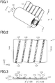
- FIG. 1 A configuration of the roll body will be described with reference to Figs. 1 to 6 .
- Figs. 1 and 2 first regions are shown dotted for the ease of discriminating the first regions from second regions.
- the roll body 10 includes a core 11 and a sheet 12.
- the core 11 extends along an axial direction and has an outer peripheral surface 11S.
- the sheet 12 has a belt-like shape extending along an extending direction D1 and is wound on the outer peripheral surface 11S of the core 11 along a circumferential direction DC.
- the sheet 12 is supported by the core 11 and thus is less prone to change in shape.
- the sheet 12 is a multi-layer body that is rolled in a cylindrical shape extending along the axial direction.
- the roll body 10 is formed from the core 11 and the sheet 12 but may be formed only form the sheet 12.
- the core 11 is removed from the sheet 12 after the sheet 12 is wound.
- the space defined by the sheet 12 is a core space.
- the core 11 has a cylindrical shape and is rotatable around a rotation axis A.
- the direction in which the rotation axis A extends is the axial direction.
- the axial direction is also the direction in which the cylindrical sheet 12 extends.
- the direction of the rotation of the core 11 around the rotation axis A along the outer peripheral surface 11S of the core 11 is the circumferential direction DC of the core 11.
- the circumferential direction DC is also the direction along the outer peripheral surface of the sheet 12.
- the sheet 12 is rolled a plurality of times on the outer peripheral surface 11S of the core 11.
- the direction orthogonal to the extending direction D1 is a width direction D2.
- the sheet 12 When unrolled, the sheet 12 has a belt-like shape that extends along the extending direction D1 and the width direction D2, and the length of the sheet 12 along the extending direction D1 is significantly longer than the length of the sheet 12 along the width direction D2.
- the sheet 12 includes a pattern section region 12P formed from a plurality of first regions 12A and a plurality of second regions 12B.
- the first regions 12A and the second regions 12B are belt-like regions extending along the first direction, and each of the belt-like regions has a shape extending along a direction crossing both the extending direction D1 and the width direction D2.
- each of the belt-like regions has a linear shape extending along a direction crossing both the extending direction D1 and the width direction D2 at an angle other than the right angle.
- the extending direction of each of the belt-like regions is a direction in which a straight line connecting start and end points of the belt-like region extends.
- the first direction crosses the extending direction D1 and the width direction D2.
- the first regions 12A and the second regions 12B are alternately arranged adjacent to each other along the arrangement direction.
- the first regions 12A and the second regions 12B are in contact with each other in the arrangement direction.
- the direction in which the first regions 12A and the second regions 12B are arranged is one direction in the plane of the sheet 12.
- the length of the first regions 12A along the direction orthogonal to the extending direction of the first regions 12A constitutes the width of the first regions 12A.
- the length of the second regions 12B along the direction orthogonal to the extending direction of the second regions 12B constitutes the width of the second regions 12B.
- the width of the first regions 12A is smaller than the width of the second regions 12B, but the width of the first regions 12A may be larger than the width of the second regions 12B or the width of the first regions 12A and the width of the second regions 12B may be equal.
- the sheet 12 is formed from a support layer 21 and a pattern structure 22.
- the pattern structure 22 is supported by the support layer 21, and the pattern structure 22 includes a plurality of element pattern structures 22a that form convex portions on a surface 12S of the sheet 12.
- the density of the element pattern structures 22a in the first regions 12A is different from the density of the element pattern structures 22a in the second regions 12B.
- the surface 12S of the sheet 12 as a concave-convex surface is formed by the surfaces of the element pattern structures 22a and the portions of the surface of the support layer 21 not covered with the element pattern structures 22a.
- the ratio of the area of the element pattern structures 22a belonging to each of the first regions 12A to the area of the first region 12A constitutes the density of the element pattern structures 22a in the first region 12A.
- the ratio of the area of the element pattern structures 22a belonging to each of the second regions 12B to the area of the second region 12B constitutes the density of the element pattern structures 22a in the second region 12B.
- the pattern structure 22 includes the plurality of element pattern structures 22a, and each of the first regions 12A includes, out of the plurality of element pattern structures 22a, an element pattern structure 22a different from the element pattern structures 22a constituting the other first regions 12A.
- the support layer 21 includes a plurality of support portions 21a, and each of the belt-like regions includes, out of the plurality of support portions 21a, a support portion 21a different from the support portions 21a constituting the other belt-like regions.
- each of the first regions 12A and the second regions 12B extends along a direction crossing both the extending direction D1 and the width direction D2 and the first regions 12A and the second regions 12B are alternately arranged, the portions of the core 11 on which the first regions 12A are wound and the portions of the core 11 on which the second regions 12B are wound vary, that is, change in the axial direction. Therefore, even if the density of the element pattern structures 22a is different between the first regions 12A and the second regions 12B, it is possible to suppress variations in the thickness of the sheet 12 along the radial direction of the core 11 in the axial direction of the core 11. This makes it possible to suppress wrinkles in the sheet 12 wound on the core 11.
- Each of the support layer 21 and the pattern structure 22 may have a single-layer structure formed from one layer or may have a multi-layer structure formed from a plurality of layers.
- the plurality of layers constituting the multi-layer structure may include layers formed from different materials.
- each of the element pattern structures 22a constituting the pattern structure 22 may have a single-layer structure formed from one layer or a multi-layer structure formed from a plurality of layers.
- the element pattern structures 22a are positioned only in the first regions 12A. Accordingly, it is possible to suppress variations in the thickness of the sheet 12 along the radial direction of the core 11 when the density of the element pattern structures 22a in the second regions 12B is a minimum.
- each of the element pattern structures 22a has a belt-like shape extending all over a corresponding one of the first regions and having a predetermined thickness. Accordingly, it is possible to suppress wrinkles in the sheet 12 wound on the core 11 when the element pattern structures 22a that form the convex portions are spaced in the arrangement direction.
- each of the element pattern structures 22a has a linear shape extending along the same direction as the first region 12A to which the element pattern structure 22a belongs, that is, the direction crossing both the extending direction D1 and the width direction D2.
- the element pattern structures 22a each extend all over a corresponding first region 12A and have substantially the same thickness.
- a recess 22b is formed between two element pattern structures 22a adjacent to each other in the arrangement direction so as to extend all over a second region 12B.
- Each of the recesses 22b has a linear shape extending along the same direction as the second regions 12B, that is, the direction crossing both the extending direction D1 and the width direction D2.
- Figs. 4 to 6 illustrate examples of a cross-sectional structure of the roll body 10 orthogonal to the axial direction of the core 11.
- the cross-sectional structures of the roll body 10 illustrated in Figs. 4 to 6 are different in the axial position.
- the cross-sectional structures illustrated in Figs. 4 to 6 include mutually different portions of the same first region 12A.
- each of Figs. 4 to 6 illustrates the sheet 12 as one circle in which one first region 12A is positioned on the foremost layer of the sheet 12 wound on the core 11.
- the sheet 12 of the roll body 10 described above is also configured as described below. That is, the sheet 12 includes the pattern section region 12P formed from the plurality of first regions 12A and the plurality of second regions 12B, and each of the first regions 12A and each of the second regions 12B are shaped to extend along the first direction. In the pattern section region 12P, the first regions 12A and the second regions 12B are alternately arranged adjacent to each other. The positions of the first regions 12A in the circumferential direction DC of the core 11 change continuously along the axial direction.
- Fig. 4 illustrates the cross-sectional structure of the roll body 10 at a first position in the axial direction.
- a first portion 12A1 of the first region 12A is located at the first position on the roll body 10 in the axial direction.
- the first portion 12A1 is located at a predetermined position in the sheet 12 in the circumferential direction DC of the core 11.
- the first portion 12A1 is located, for example, directly above the rotation axis A at the first position in the axial direction.
- a point positioned on the outer peripheral surface 11S of the core 11 directly above the rotation axis A is set as a reference point P, and a straight line extending from the rotation axis A as the center of the core 11 to the reference point P is set as a reference line LB.
- the angle formed by the reference line LB and a straight line L connecting the given point on the outer peripheral surface 11S of the core 11 and the rotation axis A is a phase.
- the phase is 0° at the first portion 12A1.
- Fig. 5 illustrates the cross-sectional structure of the roll body 10 at a second position in the axial direction different from the first position.
- a second portion 12A2 of the first region 12A is located at the second position on the roll body 10 in the axial direction.
- the second portion 12A2 is a predetermined portion of the sheet 12 in the circumferential direction DC of the core 11, which is located at the position different from the position of the first portion 12A1. That is, the first portion 12A1 and the second portion 12A2 are different in phase in the circumferential direction DC.
- the phase of the second portion 12A2 is ⁇ ° different from the phase of the first portion 12A1.
- Fig. 6 illustrates the cross-sectional structure of the roll body 10 at a third position in the axial direction different from the first position and the second position. As seen in the axial direction, the second position is sandwiched between the first position and the third position.
- a third portion 12A3 of the first regions 12A is located at the third position on the roll body 10 as seen in the axial direction.
- the third portion 12A3 is a predetermined portion of the sheet 12 in the circumferential direction DC of the core 11, which is located at the position different from the position of the first portion 12A1 and the position of the second portion 12A2.
- phase of the third portion 12A3 is different from both the phase of the first portion 12A1 and the phase of the second portion 12A2.
- the phase of the third portion 12A3 is an angle of ⁇ ° different from the phase of the first portion 12A1, and is also different from the phase ⁇ ° of the second portion 12A2.
- the first regions 12A of the sheet 12 are wound in a spiral form on the outer peripheral surface 11S of the core 11, and thus the phases of the first regions 12A in the circumferential direction of the core 11 change continuously along the axial direction.
- the portions of the core 11 on which the first regions 12A are wound and the portions of the core 11 on which the second regions 12B are wound vary in the axial direction.
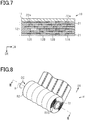
- Fig. 7 illustrates a cross-sectional view of the roll body 10 along the rotation axis A of the core 11.
- Fig. 7 illustrates the thickness of the support layer 21 and the thickness of the element pattern structures 22a included in the pattern structure 22 in an exaggerated manner.
- the portions of the sheet 12 where the first regions 12A are positioned in an axial direction DA of the core 11 shift continuously along with changes in the positions of portions of the sheet 12 where the first regions 12A are positioned in the radial direction DR of the core 11.
- the portions of the sheet 12 where the second regions 12B are positioned in the axial direction DA of the core 11 shift continuously along with changes in the positions of portions of the sheet 12 where the first regions 12A are positioned in the radial direction DR of the core 11.
- the portions of the roll body 10 where the first regions 12A are positioned in the axial direction DA and the portions of the roll body 10 where the second regions 12B are positioned in the axial direction DA vary. Therefore, even when the first regions 12A and the second regions 12B are different in thickness, the difference in thickness between the first regions 12A and the second regions 12B is not fixed in the axial direction DA. This suppresses variations in the thickness of the roll body 10 along the radial direction DR in the axial direction DA, to thereby suppress wrinkles in the sheet 12 caused by such variations in thickness.
- the sheet 12 may be wound on the core 11 such that each of the element pattern structures 22a is positioned in the support layer 21 closer to the outer peripheral surface 11S of the core 11 than the succeeding element pattern structures 22a are. That is, the sheet 12 may be wound on the core 11 such that each of the element pattern structures 22a is positioned on the surface of the sheet 12 closer to the core.
- the sheet 12 may be wound on the core 11 such that each of the element pattern structures 22a is positioned in the support layer 21 away from the outer peripheral surface 11S of the core 11 than the preceding element pattern structures 22a. That is, the sheet 12 may be wound on the core 11 such that each of the element pattern structures 22a is positioned on the surface of the sheet 12 opposite to the surface closer to the core.
- the roll body R includes a core R1 extending in the axial direction and the core R1 has an outer peripheral surface R1S.
- a sheet R2 is wound on the outer peripheral surface R1S of the core R1 along a circumferential direction DC of the core R1.
- the sheet R2 includes a plurality of first regions R2A and a plurality of second regions R2B.
- each of the first regions R2A and the second regions R2B has a linear shape extending along the extending direction D1, and the first regions R2A and the second regions R2B are alternately arranged along a width direction D2.
- the sheet R2 is formed from a support layer R21 and a pattern structure R22.
- Each of the first regions R2A is formed from a portion of the support layer R21 and element pattern structures R22a, whereas each of the second regions R2B is formed only from a portion of the support layer R21.
- the density of the element pattern structures R22a in the first regions R2A is larger than the density of the element pattern structures R22a in the second regions R2B.
- the first regions R2A and the second regions R2B extend along the extending direction D1, and the first regions R2A and the second regions R2B are alternately arranged along the width direction D2.
- the portions of the core R1 on which the first regions R2A are wound and the portions of the core R1 on which the second regions R2B are wound do not vary in the axial direction DA of the core R1. Accordingly, the portions of the roll body R where the first regions R2A overlap are thicker along the radial direction DR of the core R1, whereas the portions of the roll body R where the second regions R2B overlap are thinner along the radial direction DR.
- the roll body R in the comparative example has variations in the thickness along the radial direction DR in the axial direction of the roll body R, which causes wrinkles in the sheet R2 wound on the core R1.
- edges 12Ae of the first regions 12Aa and the edges 12Be of the second regions 12Ba may have a folded shape with a plurality of bends arranged along the extending direction D1 or may have a folded shape with one bend, or may have an arc shape.
- Each of the element pattern structures may include a plurality of prism groups.
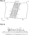
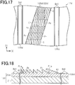
- Fig. 13 referred to later illustrates an enlarged portion of a planar structure of a sheet 12b in plan view of the sheet 12b.
- one first region 12Ab is sandwiched between two second regions 12Bb in the width direction D2 in plan view of the sheet 12b.
- the first regions 12Ab have a plurality of cells C.
- an element pattern structure 22p positioned in the first region 12Ab has a plurality of cells C.
- the plurality of cells C include triangular cells C and quadrilateral cells C in plan view of the plane of the sheet 12b.
- the plurality of cells C may include cells C different in shape in plan view of the sheet 12b or all the cells C may be equal in shape in plan view of the sheet 12b.
- Each of the cells C has a prism group formed from a plurality of prisms Pr.
- the plurality of arc-shaped prisms Pr are aligned along one direction in plan view of the sheet 12b.
- the plurality of prism groups include prism groups different in the direction in which the prisms Pr are aligned.
- the plurality of prism groups include prism groups different in the number of prisms Pr belonging to one prism group or prism groups different in the pitch of the prisms Pr in the direction in which the plurality of prisms Pr are aligned.
- All the prism groups may be equal in the direction in which the prisms Pr are aligned, or all the prism groups may be equal in the number of prisms Pr included in the prism group or may be equal in the pitch of the prisms Pr in the direction in which the plurality of prisms Pr are aligned.
- each of the element pattern structures 22p the plurality of prism groups are arranged along the extending direction D1 and the plurality of prism groups are arranged along the width direction D2.
- Each of the element pattern structures 22p may be configured such that only one prism group is positioned in the extending direction D1 and the plurality of prism groups are arranged along the width direction D2 or may be configured such that only one prism group is positioned in the width direction D2 and the plurality of prism groups are arranged along the extending direction D1.
- each of the element pattern structures 22p may be formed from only one prism group.
- the prisms Pr have an arc shape in plan view of the sheet 12b but may have a linear shape.
- the plurality of prism groups may include both prism groups formed from arc-shaped prisms Pr and prism groups formed from linear-shaped prisms Pr, or all the prism groups may have linear-shaped prisms Pr.
- Fig. 14 illustrates an example of a cross-sectional structure of the sheet 12b in the thickness direction and orthogonal to the direction in which the plurality of prisms Pr extend, in other words, a cross-sectional structure in the width direction D2 as an example of a cross-sectional structure corresponding to one prism group included in the element pattern structure 22p.
- the pitch of the prisms Pr gradually decreases along the direction in which the plurality of prisms Pr are aligned, that is, one of two inclination angles sandwiching an apex gradually decreases in the cross sections of the prisms Pr.
- the pitch of the prisms Pr may be constant as illustrated in Fig. 13 referred to earlier or both the two inclination angles sandwiching the apex may be constant in the direction in which the plurality of prisms are aligned.
- each of the prisms Pr is an asymmetrical prism with inclination angles different between both sides of an apex in a cross section of the sheet 12b along the thickness direction. More specifically, each of the prisms Pr has an apex Pra, and, in the cross section along the thickness direction of the sheet 12b, one of the inclination angles on one side of the apex Pra is a first inclination angle ⁇ 1 and the other inclination angle is a second inclination angle ⁇ 2.
- Each of the first inclination angle ⁇ 1 and the second inclination angle ⁇ 2 is an angle formed by the surface of the support layer 21 on which the element pattern structure 22p is positioned and the inclination surface of the prism Pr.
- the first inclination angle ⁇ 1 and the second inclination angle ⁇ 2 are different, and the first inclination angle ⁇ 1 is an acute angle and the second inclination angle ⁇ 2 is a right angle.
- the first inclination angle ⁇ 1 and the second inclination angle ⁇ 2 may be both acute angles.
- the first inclination angle ⁇ 1 of the prisms Pr gradually decreases along the direction in which the plurality of prisms Pr are aligned. That is, the pitch of the prisms Pr gradually increases in the direction in which the plurality of prisms Pr are aligned.
- the second inclination angle ⁇ 2 is constant in the direction in which the plurality of prisms Pr are aligned.
- both the first inclination angle ⁇ 1 and the second inclination angle ⁇ 2 may change continuously along the direction in which the plurality of prisms Pr are aligned.
- Each of the element pattern structures 22p has a support portion 22p1 positioned between each of the prisms Pr and the support layer 21 in the thickness direction of the sheet 12b.
- Each of the prisms Pr protrudes from the support portion 22p1 to the opposite side of the support portion 22p1 from the support layer 21.
- the plurality of prisms Pr are connected together via the support portion 22p1.
- the element pattern structure 22p may not necessarily have the support portion 22p1.
- the material for the element pattern structures 22p may be a light transmissive material or a material that has a property of reflecting most of light incident on the element pattern structures 22p.
- the material for the element pattern structures 22p may be any of various light-transmissive resins and dielectric substances, for instance.
- the material for the element pattern structure 22p may be a metal, for example.
- the element pattern structures 22p may include both a layer formed from a light transmissive material and a layer formed from a light reflecting material.
- Each of the element pattern structures 22p includes cells C different in the direction in which the plurality of prisms Pr are aligned and cells C different in the number of prisms Pr included in one prism group. This makes it possible to change the property of transmitting light and the property of reflecting light between the cells C different in the direction in which the plurality of prisms Pr are arranged and between the cells C different in the number of prisms Pr included in one prism group.
- each of the first regions including the plurality of prisms Pr may be a prism portion, and each of the first regions may include buffer portions sandwiching the prism portion in the width direction D2.
- the height of the buffer portions is smaller than the height of the prism portion, and the buffer portions include a concave-convex surface opposite to the surface in contact with the support layer 21.
- Each of the first regions may further include transition portions between the prism portion and the buffer portions in the width direction D2.
- the height of the transition portions is a dimension between the height of the prism portion and the height of the buffer portions, for example.
- the heights of the prism portion, the buffer portions, and the transition portions take the respective maximum values of these portions. This sheet will be described in detail with reference to Figs. 15 and 16 .
- Fig. 15 illustrates an enlarged portion of a planar structure of a sheet 12c in plan view of the sheet 12c.
- Fig. 16 illustrates a cross-sectional structure of the sheet 12c along the thickness direction and orthogonal to the direction in which the plurality of prisms Pr extend.
- the first region 12Ab includes a prism portion Ac1 extending along a direction crossing the extending direction D1 and the width direction D2, two buffer portions Ac2, and two transition portions Ac3.
- the two buffer portions Ac2 sandwich the prism portion Ac1 therebetween in the width direction D2.
- Each of the transition portions Ac3 is positioned between the prism portion Ac1 and a corresponding buffer portion Ac2.
- the buffer portions Ac2 and the transition portions Ac3 extend along the extending direction of the prism portion Ac1.
- the total area of the buffer portions Ac2 is preferably larger than the area of the prism portion Ac1, and more preferably, the area of each of the buffer portions Ac2 is larger than the area of the prism portion Ac1.
- the total width of the buffer portions Ac2 is preferably larger than the width of the prism portion Ac1, and more preferably, the width of each of the buffer portions Ac2 is larger than the width of the prism portion Ac1.
- each of the buffer portions Ac2 includes a concave-convex surface on the side opposite to the surface in contact with the support layer 21.
- the concave-convex surface can be a concave-convex surface with the function to diffract light, the function to prevent reflection of light, the function to scatter light, and the function to interfere with light.
- the concave-convex surface can also include a plurality of portions having different functions.
- Each of the transition portions Ac3 can include a concave-convex surface on the side opposite to the surface in contact with the support layer 21 similarly to the buffer portions Ac2.
- the concave-convex surface of each of the transition portions Ac3 can be configured in the same manner as that of each of the buffer portions Ac2.
- the surface of each of the transition portions Ac3 on the side opposite to the surface in contact with the support layer 21 may be an inclined surface.
- the inclined surface has an inclination so that the height of the transition portion Ac3 gradually decreases along the direction from the prism portion Ac1 to the buffer portion Ac2.
- the prism portion Ac1, the buffer portions Ac2, and the transition portions Ac3 can be integrated as one layer. Accordingly, it is possible to suppress misalignment among the prism portion Ac1, the buffer portions Ac2, and the transition portions Ac3.
- the first regions 12Ac may be formed by using one original plate, and this original plate may be obtained by connecting together an original plate for the prism portion, an original plate for the buffer portions, and an original plate for the transition portions.
- the buffer portions Ac2 included in the first region 12Ac are subjected to a pressure of a magnitude between the pressure on the prism portion Ac1 and the pressure on the second region 12Bc. Accordingly, it is possible to suppress an abrupt change in the pressure between the pressure on the prism portion Ac1 and the pressure on the second region 12Bc. This further suppresses the deformation of the prism portion Ac1 when the sheet 12c is wound.
- transition portions Ac3 included in each of the first regions 12Ac can reduce the difference in height between the prism portion Ac1 and the buffer portions Ac2. This further suppresses the deformation of the prism portion Ac1.
- Each of the first regions 12Ab may include the prism portion Ac1 extending along a direction crossing the extending direction D1 and the width direction D2, one buffer portion Ac2 on one side of the prism portion Ac1 in the width direction D2, and one transition portion Ac3 between the prism portion Ac1 and the buffer portion Ac2.
- Each of the first regions 12Ab may include the prism portion Ac1 extending along a direction crossing the extending direction D1 and the width direction D2 and only one buffer portion Ac2 adjacent to the prism portion Ac1.
- Each of the first regions 12Ab may include the prism portion Ac1 extending along a direction crossing the extending direction D1 and the width direction D2 and only two buffer portions Ac2 sandwiching the prism portion Ac1 in the width direction D2.
- Each of the first regions 12Ab may include the prism portion Ac1 extending along a direction crossing the extending direction D1 and the width direction D2, the two buffer portions Ac2 sandwiching the prism portion Ac1, and one transition portion Ac3 between any one of the two buffer portions Ac2 and the prism portion Ac1, with the other buffer portion Ac2 and the prism portion Ac1 being adjacent to each other.
- first region 12Ad is sandwiched between two second regions 12Bd in the width direction D2 as illustrated in Fig. 17 .
- the first region 12Ad has a plurality of cells C similarly to the first region 12Ab described above.
- Each of the second regions 12Bd includes linear projections Bd1 extending along the extending direction D1.
- Each of the second regions 12Bd includes a plurality of linear projections Bd1, and the plurality of projecting streaks Bd1 are spaced along the width direction D2.
- Each of the second regions 12Bd may include only one linear projection Bd1.
- the sheet 12d includes a support layer 21 and a pattern layer 23d.
- the first regions 12Ad and the second regions 12Bd include mutually different portions in the pattern layer 23d.
- a plurality of prisms Pr included in each of the first region 12Ad constitute an element pattern structure 22p, and the first regions 12Ad are thicker portions of the pattern layer 23d.
- the second regions 12Bd are thinner portions of the pattern layer 23d not including the element pattern structures 22p.
- the pattern layer 23d when the pattern layer 23d is formed on the support layer 21, the following advantageous effects can be obtained.
- a film coating for forming the pattern layer 23d is formed on the support layer 21, and then an original plate for forming the prisms Pr is pressed against the film coating.
- the original plate has a pattern corresponding to the linear projections Bd1 to form the linear projections Bd1 concurrently with the prisms Pr. Accordingly, the pattern of the original plate is pressed against the portions of the film coating for forming the pattern layer 23d corresponding to the second regions 12Bd, too. This suppresses lift of the portions of the film coating corresponding to the second regions 12Bd from the support layer 21.
- each of the second regions 12Bd includes the linear projections Bd1, even if a portion of the second region 12Bd contacts another portion of the second region 12Bd when the sheet 12d is wound on the core 11, it is possible to suppress occurrence of blocking between these portions as compared to the case in which each of the second regions 12Bd includes no linear projections.
- the portion of the pattern layer 23d corresponding to each of the first regions 12Ad may include at least one of the buffer portions Ac2 and the transition portions Ac3.
- the density of the element pattern structures in the first regions and the density of the element pattern structures in the second regions are different.
- the present invention is not limited to this but the density of the element pattern structures in the first regions and the density of the element pattern structures in the second regions may be equal.
- the arrangement of the element pattern structures in the first regions and the arrangement of the element pattern structures in the second regions are different.
- the density of the element pattern structures in the first regions and the density of the element pattern structures in the second regions may be different and the arrangement of the element pattern structures in the first regions and the arrangement of the element pattern structures in the second regions may be different.
- a second embodiment of a roll body will be described with reference to Figs. 19 to 24 .
- the roll body in the second embodiment is different from the roll body in the first embodiment in that each of the first regions includes a plurality of element pattern structures. This difference will be described below in detail and detailed description of components in common with the roll body in the first embodiment will be omitted. Configurations of first to fifth examples of the roll body will be described below in sequence.
- each of first regions 30A and second regions 30B has a linear shape extending along a direction crossing both the extending direction D1 and the width direction D2.
- the sheet 30 is formed from a support layer 31 and a pattern structure 32.
- the pattern structure 32 is formed from a plurality of element pattern structures 32a, and the plurality of element pattern structure 32a belong to one first region 30A.
- the pattern structure 32 includes two or more kinds of element pattern structures 32a different in shape in plan view of the sheet 30. Accordingly, the shape of the pattern structures 32 can be made complicated as compared to the configuration in which all the element pattern structures 32a have the same shape.
- each of the element pattern structures 32a is a portion with a predetermined thickness.
- the pattern structure 32 is positioned in the first regions 30A but is not positioned in the second regions 30B.
- the plurality of element pattern structures 32a are separated from each other along the extending direction of the first region 30A.
- Each of the element pattern structures 32a has a shape representing one letter of the alphabet in plan view of the sheet 30.
- Each of the element pattern structures 32a has a shape representing any of letters "G”, “E”, “N”, “U”, and "I” of the alphabet.
- the sheet 30 includes the support layer 31 and a plurality of element pattern structure groups 32b that are formed on the surface of the sheet 30 and are arranged cyclically along the extending direction D1.
- Each of the element pattern structure groups 32b is formed from a plurality of element pattern structures 32a that are supported by the support layer 31 and form convex portions on the surface of the sheet 30.
- one element pattern structure group 32b is formed by element pattern structures 32a having the shapes representing the letters "G", "E", “N", “U”, “I”, "N", and "E”.
- the plurality of element pattern structures 32a constituting one element pattern structure group 32b are arranged along a direction crossing both the extending direction D1 and the width direction D2.
- the plurality of element pattern structure groups 32b are repeatedly provided in a predetermined cycle in a belt-like region of the sheet 30 extending along the extending direction D1 and occupying a portion of the sheet 30 in the width direction.
- an element pattern structure group region Gr is defined by surrounding an aggregate of a plurality of element pattern structures 32a constituting one element pattern structure group 32b with an envelope contour line OL in contact with a portion of edge of each of the element pattern structures 32a.
- the envelope contour line OL is in contact with all the element pattern structures 32a belonging to one element pattern structure group 32b.
- the envelope contour line OL is preferably set to include a linear line extending in a direction in which the element pattern structures 32a are arranged.
- a line parallel to the extending direction D1 is a reference line LD.
- the reference line LD is set to overlap the sheet 30 but may be set to be separate from the sheet 30.
- the distance from at least one end portion of the element pattern structure group region GR in the width direction D2 to the reference line LD changes cyclically along the extending direction D1.
- the distance from each end portion of the element pattern structure group region GR in the width direction D2 to the reference line LD changes within one element pattern structure group region GR, and the element pattern structure group region GR is repeated cyclically along the extending direction D1 so that the distance from each end portion to the reference line LD changes cyclically along the extending direction D1.
- first regions 40A and second regions 40B have a linear shape extending along a direction crossing both the extending direction D1 and the width direction D2.
- the sheet 40 is formed from a support layer 41 and a pattern structure 42, and the pattern structure 42 includes a plurality of element pattern structure groups 42b.
- Each of the element pattern structure groups 42b is formed from a plurality of element pattern structures 42a.
- Each of the first regions 40A and each of the second regions 40B includes the element pattern structure group 42b.
- the plurality of element pattern structures 42a belonging to one element pattern structure group 42b are separated from each other along the width direction D2.
- the plurality of element pattern structures 42a belonging to each of the element pattern structure groups 42b are configured in the same manner as the plurality of element pattern structures 32a in the first example.
- the plurality of element pattern structure groups 42b belonging to one first region 40A are separated from each other along a direction crossing both the extending direction D1 and the width direction D2.
- the plurality of element pattern structure groups 42b are preferably separated from each other along a direction crossing both the extending direction D1 and the width direction D2 similarly to the plurality of element pattern structure groups 42b belonging to one first region 40A.
- the number of the element pattern structure groups 42b belonging to one first region 40A is larger than the number of the element pattern structure groups 42b belonging to one second region 40B. More specifically, three element pattern structure groups 42b belong to one first region 40A, and one element pattern structure group 42b belongs to one second region 40B.
- the number of the element pattern structure groups 42b belonging to one first region 40A may be other than three and the number of the element pattern structure groups 42b belonging to one second region 40B may be other than one.
- the number of the element pattern structure groups 42b belonging to each first region 40A may be smaller than the number of the element pattern structure groups 42b belonging to each second region 40B.
- the shape of the pattern structure 42 becomes more complicated in plan view of the sheet 40 as compared with a configuration in which only the first regions 40A include the element pattern structure groups 42b.
- the sheet 40 includes the support layer 41 and the plurality of element pattern structure groups 42b that are formed on the surface of the sheet 40 and are arranged cyclically along the extending direction D1.
- Each of the element pattern structure groups 42b is formed from a plurality of element pattern structures 42a that are supported by the support layer 41 and form convex portions on the surface of the sheet 40.
- the plurality of element pattern structures 42a constituting one element pattern structure group 42b are arranged along the width direction D2.
- Each of the element pattern structure groups 42b has a length along substantially the entire sheet 40 in the width direction D2 and the plurality of element pattern structure groups 42b are repeated cyclically along the extending direction D1.
- the element pattern structure groups 42b of which the center is substantially arranged with the center of the sheet 40 as seen in the width direction D2 are alternately positioned. Between those element pattern structure groups 42b, the element pattern structure group 42b closer to one end portion and the element pattern structure group 42b closer to the other end portion are alternately positioned in the width direction D2.
- the envelope contour line OL is in contact with all the element pattern structures 42a belonging to one element pattern structure group 42b.
- the envelope contour line OL is preferably set to include a straight line extending along the direction in which the element pattern structures 42a are arranged.
- the distance from each end portion of the element pattern structure group region GR in the width direction D2 to the reference line LD changes cyclically along the extending direction D1 among the element pattern structure group regions GR.
- first regions 50A and second regions 50B extend along a direction crossing both the extending direction D1 and the width direction D2, and the edge of each of the first regions 50A and the second regions 50B along the extending direction of the regions has a folded shape with a plurality of bends.
- Each of the first regions 50A and the second regions 50B has a belt-like shape with a plurality of constricted portions along the extending direction of the regions.
- the first regions 50A and the second regions 50B are substantially equal in width.
- the sheet 50 is formed from a support layer 51 and a pattern structure 52, and a plurality of element pattern structures 52a belong to one first region 50A. In each of the first regions 50A, the plurality of element pattern structures 52a are separated from each other along the extending direction of the first region 50A. In plan view of the sheet 50, each of the element pattern structures 52a has a hexagonal shape, and out of the six sides of the element pattern structure 52a, two parallel sides extend along the width direction D2.
- one element pattern structure 52a belongs to one second region 50B.
- the element pattern structure 52a is positioned in the center in the width direction D2, and the position of the element pattern structure 52a in the second region 50B in the width direction D2 is equal to the position of one element pattern structure 52a in each of the first regions 50A in the width direction D2.
- the plurality of element pattern structures 52a including the element pattern structures 52a belonging to the second regions 50B are aligned along the extending direction D1. All the element pattern structures 52a have the same shape.
- the third example even if all the element pattern structures have the same shape, it is possible to suppress continuous winding of the element pattern structures at a predetermined position in the axial direction of the core 11, thereby suppressing variations in the thickness of the sheet 50 along the radial direction of the core 11.
- the sheet 50 includes the support layer 51 and the plurality of element pattern structure groups 52b that are formed on the surface of the sheet 50 and arranged cyclically along the extending direction D1.
- Each of the element pattern structure groups 52b is formed from a plurality of element pattern structures 52a that are supported by the support layer 51 and form convex portions on the surface of the sheet 50.
- one element pattern structure group 52b is formed from the plurality of hexagonal element pattern structures 52a.
- the plurality of element pattern structures 52a constituting one element pattern structure group 52b are arranged along a direction crossing the extending direction D1.
- the plurality of element pattern structure groups 52b are separated from each other in the extending direction D1, and one element pattern structure 52a is positioned between two element pattern structure groups 52b in the extending direction D1.
- the envelope contour line OL is set partially along sides of each of the element pattern structures 52a.
- the sides defining the end portions of the element pattern structure group region GR in the width direction D2 are inclined with respect to both the extending direction D1 and the width direction D2. Accordingly, the distance from each end portion of the element pattern structure group region GR in the width direction D2 to the reference line LD changes within one element pattern structure group 52b, and the thus configured element pattern structure group region GR is repeated along the extending direction D1 so that the distance from the end portion to the reference line LD changes cyclically along the extending direction D1.
- first regions 60A and second regions 60B are arranged along a direction crossing both the extending direction D1 and the width direction D2.
- the edge of each of the first regions 60A along the extending direction of the first region 60A has a folded shape with a plurality of bends, and each of the first regions 60A has a belt-like shape with a plurality of constricted portions along the extending direction of the first region 60A.
- Each of the second regions 60B has a belt-like shape with a plurality of bends.
- the first regions 60A are wider than the second regions 60B.
- the sheet 60 is formed from a support layer 61 and a pattern structure 62, and a plurality of element pattern structures 62a belong to one first region 60A.
- the plurality of element pattern structures 62a have the same shape in plan view of the sheet 60.
- Each of the element pattern structures 62a has a hexagonal shape, and out of the six sides of the element pattern structure 62a, two parallel sides extend along the extending direction D1.
- the plurality of element pattern structures 62a belonging to one first region 60A are spaced along the extending direction of the first regions 60A.
- no element pattern structure 62a belongs to the second regions 60B. That is, each of the second regions 60B is formed only from a portion of the support layer 61.
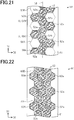
- the sheet 60 includes the support layer 61 and a plurality of element pattern structure groups 62b that are formed on the surface of the sheet 60 and arranged cyclically along the extending direction D1 as illustrated in Fig. 23 .
- Each of the element pattern structure groups 62b is formed from a plurality of element pattern structures 62a that are supported by the support layer 61 and form convex portions on the surface of the sheet 60.
- one element pattern structure group 62b is formed from the hexagonal element pattern structures 62a.
- the plurality of element pattern structures 62a constituting one element pattern structure group 62b are arranged along the width direction D2.
- the plurality of element pattern structure groups 62b are repeated in a predetermined cycle along the extending direction D1.
- the number of the element pattern structures 62a belonging to each element pattern structure group 62b is different.
- two kinds of element pattern structure groups 62b different in the positions of the end portions in the width direction D2 are alternately arranged along the extending direction D1.
- one kind of element pattern structure groups 62b include three element pattern structures 62a
- the other kind of element pattern structure groups 62b include two element pattern structures 62a.
- the envelope contour line OL is set partially along sides of each of the element pattern structures 62a.
- the distance from each end portion of the element pattern structure group region GR in the width direction D2 to the reference line LD changes cyclically along the extending direction D1 among the element pattern structure group regions GR.
- first regions 70A and second regions 70B extend along a direction crossing both the extending direction D1 and the width direction D2.
- Each of the first regions 70A has a belt-like shape in which a plurality of diamond-shaped portions are aligned along the direction crossing both the extending direction D1 and the width direction D2 in plan view of the sheet 70.
- Each of the second regions 70B has a belt-like shape in plan view of the sheet 70, and the edge of each of the second regions 70B along the extending direction has a folded shape with a plurality of bends.
- Each of the second regions 70B includes hexagonal portions aligned along the extending direction of the second region 70B.
- Each of the second regions 70B has a belt-like shape with a plurality of constricted portions along the extending direction of the second region 70B.
- the sheet 70 is formed from a support layer 71 and a pattern structure 72, and a plurality of element pattern structures 72a belong to one first region 70A.
- Each of the element pattern structures 72a has a diamond shape and the plurality of element pattern structures 72a are aligned along the extending direction of the first region 70A.
- no element pattern structure 72a belongs to each of the second region 70B.
- each of the second regions 70B is formed only from a portion of the support layer 71.
- the sheet 70 includes the support layer 71 and a plurality of element pattern structure groups 72b that are formed on the surface of the sheet 70 and arranged cyclically along the extending direction D1.
- Each of the element pattern structure groups 72b is formed from the plurality of element pattern structures 72a that are supported by the support layer 71 and form convex portions on the surface of the sheet 70.
- one element pattern structure group 72b is formed from the diamond-shaped element pattern structures 72a.
- the plurality of element pattern structures 72a constituting one element pattern structure group 72b is arranged along a direction crossing both the extending direction D1 and the width direction D2.
- Each of the element pattern structure groups 72b has a length along substantially the entire sheet 70 in the width direction D2 and the plurality of element pattern structure groups 72b are repeated in a predetermined cycle along the extending direction D1.
- the envelope contour line OL is set along the outer edge of each of the element pattern structures 72a belonging to one element pattern structure group 72b.
- the sides constituting the diamond-shaped element pattern structure 72a are inclined with respect to both the extending direction D1 and the width direction D2. Accordingly, within one element pattern structure group region GR, the distance from each end portion of the element pattern structure group region GR in the width direction D2 to the reference line LD changes cyclically along the extending direction D1, so that the distance from each end portion of the element pattern structure group region GR to the reference line LD changes cyclically along the extending direction D1 among the element pattern structure group regions GR.
- Each of the element pattern structure group regions GR may be set such that the distance from one end portion of the element pattern structure group region GR in the width direction D2 to the reference line LD changes cyclically, whereas the length from the other end portion to the reference line LD is constant. According to this configuration as well, it is possible to suppress wrinkles in the sheet at least at the end portion of the element pattern structure group region GR where the distance from the reference line LD changes cyclically along the extending direction D1.
- the sheet may include a support layer and a pattern layer, and the pattern layer may be a concave-convex structure body including the pattern structure.
- portions of the pattern layer included in the second regions and having no element pattern structure may have a predetermined thickness.
- the element pattern structure groups 42b belonging to the first regions 40A and the element pattern structure groups 42b belonging to the second regions 40B may have different shapes in plan view of the sheet 40. That is, the element pattern structure groups belonging to the first regions 40A may be formed from a plurality of first element pattern structures and the element pattern structure groups belonging to the second regions 40B may be formed from second element pattern structures different from the first element pattern structures.
- the element pattern structures are not limited to the shapes described above but may have a shape representing any one of characters, numbers, symbols, and graphics in plan view of the sheet.
- the roll body in each of the examples of the second embodiment may include a sheet but may not include a core as in the modification example of the first embodiment.
- a polyethylene terephthalate film with a thickness of 23 ⁇ m was prepared as a base material, and an ink for a relief layer with the composition shown below was applied to the base material by gravure printing such that the thickness of the dried ink became 1 ⁇ m. Accordingly, six whole sheets with a length of 5000 m were prepared. Each of the whole sheets was wound on a core to obtain a roll body.
- urethane acrylate As the urethane acrylate, Hitaloid 7903 series: multifunctional (Hitaloid is a registered trademark) produced by Hitachi Chemical Co., Ltd. was used, and as the photo initiator, Irgacure 184 (Irgacure is a registered trademark) produced by BASF Corporation was used.
- each of the whole sheets was unrolled from the core, and a roll photopolymer method was used to press a cylindrical original plate with a concave-convex outer peripheral surface against the coat layer formed by the ink for relief layer to process the surface of the coat layer opposite to the surface in contact with the base material into a concave-convex surface.
- the original plate was pressed against the coat film under the conditions that the press pressure was 2 Kgf/cm 2 , the press temperature was 80°C, and the press speed was 10 m/min.
- the base material was irradiated with ultraviolet radiation from the side opposite to the side with the coat film to harden the coat film.
- the irradiation with ultraviolet radiation was performed by using a high-pressure mercury lamp and the exposure amount was set to 300 mJ/cm 2 . Accordingly, a relief layer having a sinusoidal relief surface with a depth of 120 nm and a cycle of 700 nm was formed to obtain a support layer formed from the base material and the relief layer. Then, the support layer was wound on a core to obtain a roll body.
- the support layer was fed out from the roll body, and a 70 nm-thick aluminum layer was formed by a roll-type vacuum evaporation device on the entire relief surface of the relief layer. After that, the support layer with the aluminum layer was wound on a core to obtain a roll body.
- the stacked body of the aluminum layer and the support layer was fed out from the roll body, and a mask ink with the composition shown below was applied by gravure printing to the aluminum layer to form a mask. At this time, masks different in shape were formed on the six roll bodies.
- a mask for forming the pattern layer described above with reference to Fig. 2 was formed on the first roll body to obtain the roll body in the first example, and a mask for forming the pattern layer described above with reference to Fig. 19 was formed on the second roll body to obtain the roll body in the second example.
- a mask for forming the pattern layer described above with reference to Fig. 20 was formed on the third roll body to obtain the roll body in the third example, and a mask for forming the pattern layer described above with reference to Fig. 21 was formed on the fourth roll body to obtain the roll body in the fourth example.
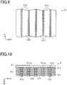
- a mask for forming the pattern layer described above with reference to Fig. 22 was formed on the fifth roll body to obtain the roll body in the fifth example, and a mask for forming the pattern layer described above with reference to Fig. 9 was formed on the sixth roll body to obtain the roll body in the first comparative example.
- a mask ink was applied to the aluminum layer such that each of the masks had a thickness of 3 ⁇ m.
- the stacked body of the support layer and the aluminum layer was subjected to alkaline etching to obtain a sheet formed from the support layer and the element pattern structures. Then, the sheet was wound on a core to obtain a roll body.
- the roll bodies in the first to fifth examples and the roll body in the first comparative example were unrolled to check visually whether the sheets had wrinkles. It has been revealed that the roll bodies in the first to fifth examples had no wrinkles in the sheets, whereas the roll body in the first comparative example had wrinkles in the sheet.
Landscapes
- Winding Of Webs (AREA)
- Laminated Bodies (AREA)
Abstract
Description
- The present invention relates to a roll body.
- Transfer foils include sheets having a pattern layer in a predetermined shape and a support layer supporting the pattern layer, for example, and may be manufactured by a roll-to-roll method (see, for example, PTL 1). In the manufacture process of transfer foil, a sheet of transfer foil or an intermediate is wound on a core so that, during the manufacture of the transfer foil or at the completion of the transfer foil, the transfer foil can be kept in storage or the intermediate of the transfer foil can be transferred between equipment.
- [PTL 1]
JP 2013-144440 A - The sheet has a belt-like shape extending along the extending direction and is wound on a core along the circumferential direction of the core. The pattern layer on the sheet may have first regions that extend linearly along the extending direction and second regions that extend linearly along the extending direction and are thinner than the first regions. When the sheet is wound on the core, portions of the core on which the first regions are wound and portions of the core on which the second regions are wound do not vary, that is, do not change in the axial direction. Accordingly, the roll body has thicker portions and thinner portions along the radial direction of the core in the axial direction of the core. As a result, the sheet has wrinkles caused by the difference in thickness between the different portions in the axial direction, which leads to reduction in the yield of the transfer foil.
- The above problem is not limited to sheets of transfer foils but is in common among roll bodies including a core and a sheet wound on the outer peripheral surface of the core along the circumferential direction of the core and roll bodies in which a sheet is wound on a core and then the core is removed.
- An object of the present disclosure is to provide a roll body that suppresses wrinkles in a sheet wound on a core.
- A roll body to solve the above problem includes a sheet as a multi-layer body that is rolled in a cylindrical shape extending along an axial direction. When unrolled, the sheet has a belt-like shape extending along an extending direction. A direction orthogonal to the extending direction is a width direction, and the sheet includes a pattern section region formed from a plurality of first regions and a plurality of second regions. The first regions and second regions each have a belt-like shape extending along a first direction and include an edge along the first direction, and the edge has a shape extending along a direction crossing both the extending direction and the width direction. In the pattern section region, the first regions and the second regions are alternately arranged adjacent to each other. The sheet is formed from a support layer and a pattern structure supported by the support layer. The roll body satisfies at least one of a condition that the density of element pattern structures in the first regions is different from the density of element pattern structures in the second regions and a condition that the arrangement of the element pattern structures in the first regions is different from the arrangement of the element pattern structures in the second regions.
- According to the above configuration, the edges of the first regions and the edges of the second regions extend along the direction crossing both the extending direction and the width direction and the first regions and the second regions are alternately arranged, so that the portions of the core on which the edges of the first regions are wound and the portions of the core on which the edges of the second regions are wound vary in the axial direction. Therefore, the difference in thickness at the boundaries between the first regions and the second regions along the radial direction of the core is likely to be reduced, thereby suppressing an abrupt change in the thickness of the roll body along the radial direction in the axial direction of the core. As a result, it is possible to suppress wrinkles in the sheet wound on the core.
- A roll body to solve the above problem includes a sheet as a multi-layer body that is rolled in a cylindrical shape extending along an axial direction. When unrolled, the sheet has a belt-like shape extending along an extending direction. The sheet includes a pattern section region formed from a plurality of first regions and a plurality of second regions, and each of the first regions and each of the second regions have a shape extending along a first direction. In the pattern section region, the first regions and the second regions are alternately arranged adjacent to each other. Each of the first regions includes an edge along the first direction, and the position of the edge of each of the first regions in a circumferential direction of the sheet changes continuously along the axial direction. The sheet is formed from a support layer and a pattern structure supported by the support layer, and the pattern structure includes a plurality of element pattern structures that form convex portions on a surface of the sheet. The roll body satisfies at least one of a condition that the density of element pattern structures in the first regions is different from the density of element pattern structures in the second regions and a condition that the arrangement of the element pattern structures in the first regions is different from the arrangement of the element pattern structures in the second regions.
- According to the above configuration, the positions of the edges of the first regions in the circumferential direction of the core change continuously, in other words, the portions of the core on which the edges of the first regions are wound and the portions of the core on which the edges of the second regions are wound vary in the axial direction. Therefore, the difference in thickness at the boundaries between the first regions and the second regions along the radial direction of the core is likely to be reduced, thereby suppressing an abrupt change in the thickness of the roll body along the radial direction of the core in the axial direction of the core. As a result, it is possible to suppress wrinkles in the sheet wound on the core.
- The roll body may further include a core that extends along the axial direction and has an outer peripheral surface, and the sheet may be wound along the outer peripheral surface of the core. According to the above configuration, the sheet is supported by the core and thus the shape of the sheet is less prone to change.
- In the roll body, the first direction may cross both the extending direction and the width direction.
- According to the above configuration, the first regions and the second regions extend along the first direction crossing both the extending direction and the width direction and the first regions and the second regions are alternately arranged, so that the portions of the core on which the edges of the first regions are wound and the portions of the core on which the edges of the second regions are wound vary in the axial direction. Therefore, it is possible to suppress variations in the thickness along the radial direction of the core in the axial direction of the core. As a result, it is possible to suppress wrinkles in the sheet wound on the core.
- In the roll body, the position of the first regions in the circumferential direction of the core may change continuously along the axial direction.
- According to the above configuration, the positions of the first regions in the circumferential direction continuously changes along the axial direction. In other words, the portions of the core on which the edges of the first regions are wound and the portions of the core on which the edges of the second regions are wound vary in the axial direction. Accordingly, it is possible to suppress variations in the thickness along the radial direction of the core between the first regions and the second regions in the axial direction of the core. As a result, it is possible to suppress wrinkles in the sheet wound on the core.
- In the roll body, the element pattern structures may be positioned only in the first regions. According to the above configuration, it is possible to suppress wrinkles in the sheet wound on the core because the density of the element pattern structures in the second regions is a minimum.
- In the above roll body, each of the element pattern structures may have a belt-like shape extending all over a corresponding one of the first regions and having a predetermined thickness.
- According to the above configuration, it is possible to suppress wrinkles in the sheet wound on the core because the element pattern structures that form convex portions are spaced in an arrangement direction.
- The above roll body may include a pattern layer as a concave-convex structure body that has the pattern structure and is supported by the support layer, the first regions may be thicker portions of the pattern layer including the element pattern structures, and the second regions may be thinner portions of the pattern layer not including the element pattern structures.
- According to the above configuration, it is possible to suppress wrinkles in the sheet wound on the core in the configuration both the first regions and the second regions include portions of the pattern layer with the predetermined thickness.
- In the above roll body, the pattern structure may include two or more kinds of the element pattern structures different in shape in plan view of the sheet.
- According to the above configuration, the shape of the pattern structure can be made more complicated compared to the configuration in which all the element pattern structures have the same shape.
- In the above roll body, the plurality of element pattern structures may each have the same shape in plan view of the sheet.
- According to the above configuration, it is possible to suppress wrinkles in the sheet wound on the core even if all the element pattern structures have the same shape.
- In the above roll body, the pattern structure may include a plurality of element pattern structure groups; each of the element pattern structure groups may be formed from the plurality of element pattern structures; each of the first regions and each of the second regions may include the element pattern structure groups, and the number of the element pattern structures belonging to each of the first regions and the number of the element pattern structures belonging to each of the second regions may be different.
- According to the above configuration, not only the first regions but also the second regions include the element pattern structure groups, and thus the shape of the pattern structure can be made more complicated in plan view of the sheet as compared to the configuration in which only the first regions include the element pattern structure groups.
- A roll body to solve the above problem includes a sheet as a multi-layer body that is rolled in a cylindrical shape extending along an axial direction, and when the sheet is unrolled, the sheet has a belt-like shape extending along an extending direction. The sheet includes a support layer and a plurality of element pattern structure groups that are formed on a surface of the sheet and are arranged cyclically along the extending direction. Each of the element pattern structure groups includes a plurality of element pattern structures that are supported by the support layer and form convex portions on the surface of the sheet. In plan view of the sheet, a region defined by surrounding an aggregate of the plurality of element pattern structures constituting one element pattern structure group with an envelope contour line in contact with a portion of an edge of each of the element pattern structures constitutes an element pattern structure group region. A line parallel to the extending direction is a reference line, and a direction orthogonal to the extending direction is a width direction. A distance from one end portion of the element pattern structure group region in the width direction to the reference line changes cyclically along the extending direction.
- According to the above configuration, the distance from at least one end portion of the element pattern structure group region in the width direction to the reference line parallel to the extending direction changes cyclically along the extending direction, and thus out of end portions of the element pattern structure group region in the width direction, the end portion where the distance to the reference line changes cyclically changes cyclically in position in the axial direction of the core. Therefore, it is possible to suppress wrinkles in the sheet wound on the core as compared to the configuration in which the position of the end portion of the sheet in the axial direction of the core does not change.
- In the above roll body, each of the convex portions may include at least one prism group in which a plurality of linear or arc-shaped prisms are aligned along one direction in plan view of the sheet, and each of the prisms is an asymmetrical prism with inclination angles different between both sides of an apex in a cross section as seen in the width direction of the sheet.
- According to the above configuration, the portions of the core on which the first regions are wound and the portions of the core on which the second regions are wound vary in the axial direction, and thus even when the element pattern structures positioned in the first regions include a plurality of prisms, it is possible to suppress deformation of the prisms caused by winding the sheet on the core.
- According to the present disclosure, it is possible to suppress wrinkles in the sheet wound on the core.
-
-
Fig. 1 is a perspective view of a structure of a roll body in a first embodiment. -
Fig. 2 is a partial planer view of a structure of a sheet included in the roll body. -
Fig. 3 is a cross-sectional view of the structure illustrated inFig. 2 taken along line II-II. -
Fig. 4 is a cross-sectional view of a structure of a core orthogonal to an axial direction. -
Fig. 5 is a cross-sectional view of the structure of the core orthogonal to the axial direction. -
Fig. 6 is a cross-sectional view of the structure of the core orthogonal to the axial direction. -
Fig. 7 is a cross-sectional view of the structure illustrated inFig. 1 taken along line I-I. -
Fig. 8 is a perspective view of a structure of a roll body in a comparative example. -
Fig. 9 is a partial planar view of a structure of a sheet included in the roll body in the comparative example. -
Fig. 10 is a cross-sectional view of the structure illustrated inFig. 8 taken along line III-III. -
Fig. 11 is a cross-sectional view of a structure of a sheet in a modification example. -
Fig. 12 is a partial planar view of the structure of the sheet in the modification example. -
Fig. 13 is a partial enlarged planar view of a structure of a sheet in a modification example. -
Fig. 14 is a partial enlarged cross-sectional view of a structure of an element pattern structure in the modification example. -
Fig. 15 is a partial enlarged planar view of a structure of a sheet in a modification example. -
Fig. 16 is a partial enlarged cross-sectional view of a structure of an element pattern structure in the modification example. -
Fig. 17 is a partial enlarged planar view of a structure of a sheet in a modification example. -
Fig.18 is a partial enlarged planar view of a structure of an element pattern structure in the modification example. -
Fig.19 is a partial planar view of a structure of a sheet included in a first example of the roll body in the second embodiment. -
Fig. 20 is a partial planar view of a structure in the sheet included in a second example of the roll body. -
Fig. 21 is a partial planar view of a structure of a sheet included in a third example of the roll body. -
Fig. 22 is a partial planar view of a structure of a sheet included in a fourth example of the roll body. -
Fig. 23 is a partial planar view of a structure of a sheet included in the fourth example of the roll body. -
Fig. 24 is a partial planar view of a structure of a sheet included in a fifth example of the roll body. - A first embodiment of a roll body will be described with reference to
Figs. 1 to 10 . Hereinafter, a configuration of the roll body, operations of the roll body, and a roll body in a comparative example will be described in sequence. - A configuration of the roll body will be described with reference to
Figs. 1 to 6 . InFigs. 1 and 2 , first regions are shown dotted for the ease of discriminating the first regions from second regions. - As illustrated in
Fig. 1 , theroll body 10 includes acore 11 and asheet 12. Thecore 11 extends along an axial direction and has an outerperipheral surface 11S. Thesheet 12 has a belt-like shape extending along an extending direction D1 and is wound on the outerperipheral surface 11S of thecore 11 along a circumferential direction DC. In theroll body 10, thesheet 12 is supported by thecore 11 and thus is less prone to change in shape. - In other words, the
sheet 12 is a multi-layer body that is rolled in a cylindrical shape extending along the axial direction. Theroll body 10 is formed from thecore 11 and thesheet 12 but may be formed only form thesheet 12. In this case, thecore 11 is removed from thesheet 12 after thesheet 12 is wound. The space defined by thesheet 12 is a core space. - The
core 11 has a cylindrical shape and is rotatable around a rotation axis A. The direction in which the rotation axis A extends is the axial direction. The axial direction is also the direction in which thecylindrical sheet 12 extends. The direction of the rotation of thecore 11 around the rotation axis A along the outerperipheral surface 11S of thecore 11 is the circumferential direction DC of thecore 11. The circumferential direction DC is also the direction along the outer peripheral surface of thesheet 12. Thesheet 12 is rolled a plurality of times on the outerperipheral surface 11S of thecore 11. - As illustrated in
Fig. 2 , the direction orthogonal to the extending direction D1 is a width direction D2. When unrolled, thesheet 12 has a belt-like shape that extends along the extending direction D1 and the width direction D2, and the length of thesheet 12 along the extending direction D1 is significantly longer than the length of thesheet 12 along the width direction D2. - The
sheet 12 includes apattern section region 12P formed from a plurality offirst regions 12A and a plurality ofsecond regions 12B. Thefirst regions 12A and thesecond regions 12B are belt-like regions extending along the first direction, and each of the belt-like regions has a shape extending along a direction crossing both the extending direction D1 and the width direction D2. In other words, each of the belt-like regions has a linear shape extending along a direction crossing both the extending direction D1 and the width direction D2 at an angle other than the right angle. The extending direction of each of the belt-like regions is a direction in which a straight line connecting start and end points of the belt-like region extends. The first direction crosses the extending direction D1 and the width direction D2. - In the plurality of belt-like regions, the
first regions 12A and thesecond regions 12B are alternately arranged adjacent to each other along the arrangement direction. Thefirst regions 12A and thesecond regions 12B are in contact with each other in the arrangement direction. The direction in which thefirst regions 12A and thesecond regions 12B are arranged is one direction in the plane of thesheet 12. - In plan view of the
sheet 12, the length of thefirst regions 12A along the direction orthogonal to the extending direction of thefirst regions 12A constitutes the width of thefirst regions 12A. In plan view of thesheet 12, the length of thesecond regions 12B along the direction orthogonal to the extending direction of thesecond regions 12B constitutes the width of thesecond regions 12B. The width of thefirst regions 12A is smaller than the width of thesecond regions 12B, but the width of thefirst regions 12A may be larger than the width of thesecond regions 12B or the width of thefirst regions 12A and the width of thesecond regions 12B may be equal. - As illustrated in
Fig. 3 , thesheet 12 is formed from asupport layer 21 and apattern structure 22. Thepattern structure 22 is supported by thesupport layer 21, and thepattern structure 22 includes a plurality ofelement pattern structures 22a that form convex portions on a surface 12S of thesheet 12. In thesheet 12, the density of theelement pattern structures 22a in thefirst regions 12A is different from the density of theelement pattern structures 22a in thesecond regions 12B. - The surface 12S of the
sheet 12 as a concave-convex surface is formed by the surfaces of theelement pattern structures 22a and the portions of the surface of thesupport layer 21 not covered with theelement pattern structures 22a. In plan view of thesheet 12, the ratio of the area of theelement pattern structures 22a belonging to each of thefirst regions 12A to the area of thefirst region 12A constitutes the density of theelement pattern structures 22a in thefirst region 12A. In addition, in plan view of thesheet 12, the ratio of the area of theelement pattern structures 22a belonging to each of thesecond regions 12B to the area of thesecond region 12B constitutes the density of theelement pattern structures 22a in thesecond region 12B. - The
pattern structure 22 includes the plurality ofelement pattern structures 22a, and each of thefirst regions 12A includes, out of the plurality ofelement pattern structures 22a, anelement pattern structure 22a different from theelement pattern structures 22a constituting the otherfirst regions 12A. Thesupport layer 21 includes a plurality ofsupport portions 21a, and each of the belt-like regions includes, out of the plurality ofsupport portions 21a, asupport portion 21a different from thesupport portions 21a constituting the other belt-like regions. - Since each of the
first regions 12A and thesecond regions 12B extends along a direction crossing both the extending direction D1 and the width direction D2 and thefirst regions 12A and thesecond regions 12B are alternately arranged, the portions of the core 11 on which thefirst regions 12A are wound and the portions of the core 11 on which thesecond regions 12B are wound vary, that is, change in the axial direction. Therefore, even if the density of theelement pattern structures 22a is different between thefirst regions 12A and thesecond regions 12B, it is possible to suppress variations in the thickness of thesheet 12 along the radial direction of the core 11 in the axial direction of thecore 11. This makes it possible to suppress wrinkles in thesheet 12 wound on thecore 11. - Each of the
support layer 21 and thepattern structure 22 may have a single-layer structure formed from one layer or may have a multi-layer structure formed from a plurality of layers. When each of thesupport layer 21 and thepattern structure 22 has a multi-layer structure, the plurality of layers constituting the multi-layer structure may include layers formed from different materials. In other words, each of theelement pattern structures 22a constituting thepattern structure 22 may have a single-layer structure formed from one layer or a multi-layer structure formed from a plurality of layers. - The
element pattern structures 22a are positioned only in thefirst regions 12A. Accordingly, it is possible to suppress variations in the thickness of thesheet 12 along the radial direction of the core 11 when the density of theelement pattern structures 22a in thesecond regions 12B is a minimum. - In each of the
first regions 12A, each of theelement pattern structures 22a has a belt-like shape extending all over a corresponding one of the first regions and having a predetermined thickness. Accordingly, it is possible to suppress wrinkles in thesheet 12 wound on the core 11 when theelement pattern structures 22a that form the convex portions are spaced in the arrangement direction. - More specifically, each of the
element pattern structures 22a has a linear shape extending along the same direction as thefirst region 12A to which theelement pattern structure 22a belongs, that is, the direction crossing both the extending direction D1 and the width direction D2. Theelement pattern structures 22a each extend all over a correspondingfirst region 12A and have substantially the same thickness. - A
recess 22b is formed between twoelement pattern structures 22a adjacent to each other in the arrangement direction so as to extend all over asecond region 12B. Each of therecesses 22b has a linear shape extending along the same direction as thesecond regions 12B, that is, the direction crossing both the extending direction D1 and the width direction D2. Thus, out of thefirst regions 12A and thesecond regions 12B, thefirst regions 12A have theelement pattern structures 22a but thesecond regions 12B do not have theelement pattern structures 22a. Accordingly, the density of theelement pattern structures 22a is different between thefirst regions 12A and thesecond regions 12B. -
Figs. 4 to 6 illustrate examples of a cross-sectional structure of theroll body 10 orthogonal to the axial direction of thecore 11. The cross-sectional structures of theroll body 10 illustrated inFigs. 4 to 6 are different in the axial position. The cross-sectional structures illustrated inFigs. 4 to 6 include mutually different portions of the samefirst region 12A. For the sake of illustration, each ofFigs. 4 to 6 illustrates thesheet 12 as one circle in which onefirst region 12A is positioned on the foremost layer of thesheet 12 wound on thecore 11. - The
sheet 12 of theroll body 10 described above is also configured as described below. That is, thesheet 12 includes thepattern section region 12P formed from the plurality offirst regions 12A and the plurality ofsecond regions 12B, and each of thefirst regions 12A and each of thesecond regions 12B are shaped to extend along the first direction. In thepattern section region 12P, thefirst regions 12A and thesecond regions 12B are alternately arranged adjacent to each other. The positions of thefirst regions 12A in the circumferential direction DC of the core 11 change continuously along the axial direction. -
Fig. 4 illustrates the cross-sectional structure of theroll body 10 at a first position in the axial direction. - As illustrated in
Fig. 4 , a first portion 12A1 of thefirst region 12A is located at the first position on theroll body 10 in the axial direction. The first portion 12A1 is located at a predetermined position in thesheet 12 in the circumferential direction DC of thecore 11. The first portion 12A1 is located, for example, directly above the rotation axis A at the first position in the axial direction. - In the circumferential direction DC of the core 11, a point positioned on the outer
peripheral surface 11S of the core 11 directly above the rotation axis A is set as a reference point P, and a straight line extending from the rotation axis A as the center of the core 11 to the reference point P is set as a reference line LB. The angle formed by the reference line LB and a straight line L connecting the given point on the outerperipheral surface 11S of thecore 11 and the rotation axis A is a phase. The phase is 0° at the first portion 12A1. -
Fig. 5 illustrates the cross-sectional structure of theroll body 10 at a second position in the axial direction different from the first position. - As illustrated in
Fig. 5 , a second portion 12A2 of thefirst region 12A is located at the second position on theroll body 10 in the axial direction. The second portion 12A2 is a predetermined portion of thesheet 12 in the circumferential direction DC of the core 11, which is located at the position different from the position of the first portion 12A1. That is, the first portion 12A1 and the second portion 12A2 are different in phase in the circumferential direction DC. The phase of the second portion 12A2 is α° different from the phase of the first portion 12A1. -
Fig. 6 illustrates the cross-sectional structure of theroll body 10 at a third position in the axial direction different from the first position and the second position. As seen in the axial direction, the second position is sandwiched between the first position and the third position. - As illustrated in
Fig. 6 , a third portion 12A3 of thefirst regions 12A is located at the third position on theroll body 10 as seen in the axial direction. The third portion 12A3 is a predetermined portion of thesheet 12 in the circumferential direction DC of the core 11, which is located at the position different from the position of the first portion 12A1 and the position of the second portion 12A2. - That is, the phase of the third portion 12A3 is different from both the phase of the first portion 12A1 and the phase of the second portion 12A2. The phase of the third portion 12A3 is an angle of β° different from the phase of the first portion 12A1, and is also different from the phase α° of the second portion 12A2.
- The
first regions 12A of thesheet 12 are wound in a spiral form on the outerperipheral surface 11S of the core 11, and thus the phases of thefirst regions 12A in the circumferential direction of the core 11 change continuously along the axial direction. In other words, the portions of the core 11 on which thefirst regions 12A are wound and the portions of the core 11 on which thesecond regions 12B are wound vary in the axial direction. - Accordingly, even if the density of the
element pattern structures 22a in thefirst regions 12A and the density of theelement pattern structures 22a in thesecond regions 12B are different, it is possible to suppress variations in the thickness of theroll body 10 in the radial direction of the core 11, along the axial direction of thecore 11. Therefore, it is possible to suppress wrinkles in thesheet 12 wound on thecore 11. - Operations of the
roll body 10 will be described with reference toFig. 7 . -
Fig. 7 illustrates a cross-sectional view of theroll body 10 along the rotation axis A of thecore 11. For the sake of illustration,Fig. 7 illustrates the thickness of thesupport layer 21 and the thickness of theelement pattern structures 22a included in thepattern structure 22 in an exaggerated manner. - As illustrated in
Fig. 7 , when thesheet 12 is wound on thecore 11, the portions of thesheet 12 where thefirst regions 12A are positioned in an axial direction DA of the core 11 shift continuously along with changes in the positions of portions of thesheet 12 where thefirst regions 12A are positioned in the radial direction DR of thecore 11. In addition, the portions of thesheet 12 where thesecond regions 12B are positioned in the axial direction DA of the core 11 shift continuously along with changes in the positions of portions of thesheet 12 where thefirst regions 12A are positioned in the radial direction DR of thecore 11. - Accordingly, the portions of the
roll body 10 where thefirst regions 12A are positioned in the axial direction DA and the portions of theroll body 10 where thesecond regions 12B are positioned in the axial direction DA vary. Therefore, even when thefirst regions 12A and thesecond regions 12B are different in thickness, the difference in thickness between thefirst regions 12A and thesecond regions 12B is not fixed in the axial direction DA. This suppresses variations in the thickness of theroll body 10 along the radial direction DR in the axial direction DA, to thereby suppress wrinkles in thesheet 12 caused by such variations in thickness. - As illustrated in
Fig. 7 , thesheet 12 may be wound on the core 11 such that each of theelement pattern structures 22a is positioned in thesupport layer 21 closer to the outerperipheral surface 11S of the core 11 than the succeedingelement pattern structures 22a are. That is, thesheet 12 may be wound on the core 11 such that each of theelement pattern structures 22a is positioned on the surface of thesheet 12 closer to the core. Alternatively, thesheet 12 may be wound on the core 11 such that each of theelement pattern structures 22a is positioned in thesupport layer 21 away from the outerperipheral surface 11S of the core 11 than the precedingelement pattern structures 22a. That is, thesheet 12 may be wound on the core 11 such that each of theelement pattern structures 22a is positioned on the surface of thesheet 12 opposite to the surface closer to the core. - A configuration of a roll body in a comparative example will be described with reference to
Figs. 8 to 10 . - As illustrated in
Fig. 8 , similarly to theroll body 10 in the first embodiment described above, the roll body R includes a core R1 extending in the axial direction and the core R1 has an outer peripheral surface R1S. A sheet R2 is wound on the outer peripheral surface R1S of the core R1 along a circumferential direction DC of the core R1. - As illustrated in
Fig. 9 , the sheet R2 includes a plurality of first regions R2A and a plurality of second regions R2B. In plan view of the sheet R2, each of the first regions R2A and the second regions R2B has a linear shape extending along the extending direction D1, and the first regions R2A and the second regions R2B are alternately arranged along a width direction D2. - As illustrated in
Fig. 10 , the sheet R2 is formed from a support layer R21 and a pattern structure R22. Each of the first regions R2A is formed from a portion of the support layer R21 and element pattern structures R22a, whereas each of the second regions R2B is formed only from a portion of the support layer R21. - Therefore, in the roll body R, similarly to the
roll body 10 in the first embodiment, the density of the element pattern structures R22a in the first regions R2A is larger than the density of the element pattern structures R22a in the second regions R2B. - As described above, the first regions R2A and the second regions R2B extend along the extending direction D1, and the first regions R2A and the second regions R2B are alternately arranged along the width direction D2. Thus, when the sheet R2 is wound on the core R1, the portions of the core R1 on which the first regions R2A are wound and the portions of the core R1 on which the second regions R2B are wound do not vary in the axial direction DA of the core R1. Accordingly, the portions of the roll body R where the first regions R2A overlap are thicker along the radial direction DR of the core R1, whereas the portions of the roll body R where the second regions R2B overlap are thinner along the radial direction DR.
- Accordingly, the roll body R in the comparative example has variations in the thickness along the radial direction DR in the axial direction of the roll body R, which causes wrinkles in the sheet R2 wound on the core R1.
- As described above, according to the first embodiment of the roll body, the following advantageous effects can be obtained.
- (1) The portions of the core 11 on which the
first regions 12A are wound and the portions of the core 11 on which thesecond regions 12B are wound vary in the axial direction DA. This suppresses variations in the thickness of theroll body 10 along the radial direction DA of the core 11 in the axial direction DA of thecore 11. Therefore, it is possible to suppress wrinkles in thesheet 12 wound on thecore 11. - (2) It is possible to suppress variations in the thickness of the
sheet 12 along the radial direction DR of the core 11 when the density of theelement pattern structures 22a in thesecond regions 12B is a minimum. - (3) It is possible to suppress wrinkles in the
sheet 12 wound on the core 11 when theelement pattern structures 22a forming the convex portions are spaced in the arrangement direction.
The first embodiment described above can be appropriately modified as described below.
Thefirst regions 12A and thesecond regions 12B are not limited to a linear shape but may have a folded shape with at least one bend or may have a curved shape with at least one bend. Even in this configuration, the advantageous effect equivalent to (3) described above can be obtained if theelement pattern structures 22a are positioned in the entirefirst regions 12A and have a predetermined thickness. In addition, the advantageous effect equivalent to (2) described above can be obtained if theelement pattern structures 22a are positioned only in thefirst regions 12A. Further, the advantageous effect equivalent to (1) described above can be obtained if thefirst regions 12A and thesecond regions 12B extend along the direction crossing both the extending direction D1 and the width direction D2 and are alternately arranged along the arrangement direction.
Theelement pattern structures 22a may be repeatedly provided in a predetermined cycle along the extending direction D1. Specifically, each of theelement pattern structures 22a may have a linear shape extending along the direction crossing both the extending direction D1 and the width direction D2 and its length in the extending direction D1 may be shorter than the length of thesheet 12 in the extending direction D1.
As illustrated inFig. 11 , thesheet 12 may include apattern layer 23. Thepattern layer 23 may be a concave-convex structure body supported by thesupport layer 21; thefirst regions 12A may be thicker portions of thepattern layer 23 including theelement pattern structures 22a; and thesecond regions 12B may be thin portions of thepattern layer 23 not including theelement pattern structures 22a. Specifically, thepattern layer 23 may havefirst parts 23a included in thefirst regions 12A andsecond parts 23b included in thesecond regions 12B, and portions of thefirst parts 23a protruding more than thesecond parts 23b may be theelement pattern structures 22a. In this configuration, thepattern structure 22 is formed from the portions of thefirst parts 23a protruding more than thesecond parts 23b, and the concave-convex surface of thepattern layer 23 is an example of the surface 12S of thesheet 12.
According to the above configuration, the following advantageous effects can be obtained. - (4) It is possible to suppress wrinkles in the
sheet 12 wound on the core 11 when the portions of thepattern layer 23 are formed from thefirst regions 12A and thesecond regions 12B which are different in thickness.
Thefirst regions 12A and thesecond regions 12B may not necessarily extend along the direction crossing both the extending direction D1 and the width direction D2. That is, thefirst regions 12A and thesecond regions 12B may extend along the extending direction D1 or may extend along the width direction D2. In this configuration, the edge of each of thefirst regions 12A and thesecond regions 12B, that is, the edge of each of the belt-like regions along the extending direction of the belt-like region extend at least partially along a direction crossing both the extending direction D1 and the width direction D2. In other words, the edge of each of the belt-like regions includes a portion not extending along the extending direction D1 and not extending along the width direction D2.
For example, as illustrated inFig. 12 , in asheet 12a, first regions 12Aa have a shape extending along the extending direction D1 and include edges 12Ae extending along the extending direction of the first regions 12Aa. Each of the edges 12Ae has a wave-line shape with a plurality of bends arranged along the extending direction D1 so that the edge 12Ae extends along a direction crossing both the extending direction D1 and the width direction D2. That is, each of the edges 12Ae includes portions not extending along the extending direction and not extending along the width direction D2.
The edges 12Ae of the first regions 12Aa are also edges 12Be of the second regions 12Ba adjacent to the first regions 12Aa. That is, each of the edges 12Be of the second regions 12Ba has a wave-line shape with a plurality of bends arranged along the extending direction D1 so that the edge 12Be extends along a direction crossing both the extending direction D1 and the width direction D2. That is, each of the edges 12Be includes portions not extending along the extending direction and not extending along the width direction D2.
In other words, the positions of the edges 12Ae of the first regions 12Aa in the circumferential direction of the core 11 change continuously along the axial direction.
According to this configuration, the following advantageous effects can be obtained. - (5) The portions of the core 11 on which the edges 12Ae of the first regions 12Aa are wound and the portions of the core 11 on which the edges 12Be of the second regions 12Ba are wound vary in the axial direction. Therefore, the difference in thickness at the boundaries between the first regions 12Aa and the second regions 12Ba is likely to be reduced along the radial direction of the
core 11. Accordingly, even when the density of the element pattern structures is different between these regions, it is possible to suppress an abrupt change in the thickness of the roll body along the radial direction of the core 11 in the axial direction of thecore 11. This suppresses wrinkles in thesheet 12a wound on thecore 11. - In the configuration described above with reference to
Fig. 12 , the edges 12Ae of the first regions 12Aa and the edges 12Be of the second regions 12Ba may have a folded shape with a plurality of bends arranged along the extending direction D1 or may have a folded shape with one bend, or may have an arc shape. - Each of the element pattern structures may include a plurality of prism groups.
Fig. 13 referred to later illustrates an enlarged portion of a planar structure of asheet 12b in plan view of thesheet 12b. - As illustrated in
Fig. 13 , one first region 12Ab is sandwiched between two second regions 12Bb in the width direction D2 in plan view of thesheet 12b. The first regions 12Ab have a plurality of cells C. In other words, anelement pattern structure 22p positioned in the first region 12Ab has a plurality of cells C. The plurality of cells C include triangular cells C and quadrilateral cells C in plan view of the plane of thesheet 12b. As described above, the plurality of cells C may include cells C different in shape in plan view of thesheet 12b or all the cells C may be equal in shape in plan view of thesheet 12b. - Each of the cells C has a prism group formed from a plurality of prisms Pr. In each of the prism groups, the plurality of arc-shaped prisms Pr are aligned along one direction in plan view of the
sheet 12b. The plurality of prism groups include prism groups different in the direction in which the prisms Pr are aligned. In addition, the plurality of prism groups include prism groups different in the number of prisms Pr belonging to one prism group or prism groups different in the pitch of the prisms Pr in the direction in which the plurality of prisms Pr are aligned. All the prism groups may be equal in the direction in which the prisms Pr are aligned, or all the prism groups may be equal in the number of prisms Pr included in the prism group or may be equal in the pitch of the prisms Pr in the direction in which the plurality of prisms Pr are aligned. - In each of the
element pattern structures 22p, the plurality of prism groups are arranged along the extending direction D1 and the plurality of prism groups are arranged along the width direction D2. Each of theelement pattern structures 22p may be configured such that only one prism group is positioned in the extending direction D1 and the plurality of prism groups are arranged along the width direction D2 or may be configured such that only one prism group is positioned in the width direction D2 and the plurality of prism groups are arranged along the extending direction D1. Alternatively, each of theelement pattern structures 22p may be formed from only one prism group. - The prisms Pr have an arc shape in plan view of the
sheet 12b but may have a linear shape. The plurality of prism groups may include both prism groups formed from arc-shaped prisms Pr and prism groups formed from linear-shaped prisms Pr, or all the prism groups may have linear-shaped prisms Pr. -
Fig. 14 illustrates an example of a cross-sectional structure of thesheet 12b in the thickness direction and orthogonal to the direction in which the plurality of prisms Pr extend, in other words, a cross-sectional structure in the width direction D2 as an example of a cross-sectional structure corresponding to one prism group included in theelement pattern structure 22p. In the example ofFig. 14 , the pitch of the prisms Pr gradually decreases along the direction in which the plurality of prisms Pr are aligned, that is, one of two inclination angles sandwiching an apex gradually decreases in the cross sections of the prisms Pr. However, in the direction in which the plurality of prisms Pr are aligned, the pitch of the prisms Pr may be constant as illustrated inFig. 13 referred to earlier or both the two inclination angles sandwiching the apex may be constant in the direction in which the plurality of prisms are aligned. - As illustrated in
Fig. 14 , each of the prisms Pr is an asymmetrical prism with inclination angles different between both sides of an apex in a cross section of thesheet 12b along the thickness direction. More specifically, each of the prisms Pr has an apex Pra, and, in the cross section along the thickness direction of thesheet 12b, one of the inclination angles on one side of the apex Pra is a first inclination angle θ1 and the other inclination angle is a second inclination angle θ2. Each of the first inclination angle θ1 and the second inclination angle θ2 is an angle formed by the surface of thesupport layer 21 on which theelement pattern structure 22p is positioned and the inclination surface of the prism Pr. The first inclination angle θ1 and the second inclination angle θ2 are different, and the first inclination angle θ1 is an acute angle and the second inclination angle θ2 is a right angle. Alternatively, the first inclination angle θ1 and the second inclination angle θ2 may be both acute angles. - The first inclination angle θ1 of the prisms Pr gradually decreases along the direction in which the plurality of prisms Pr are aligned. That is, the pitch of the prisms Pr gradually increases in the direction in which the plurality of prisms Pr are aligned. In contrast to this, the second inclination angle θ2 is constant in the direction in which the plurality of prisms Pr are aligned. Alternatively, both the first inclination angle θ1 and the second inclination angle θ2 may change continuously along the direction in which the plurality of prisms Pr are aligned.
- Each of the
element pattern structures 22p has a support portion 22p1 positioned between each of the prisms Pr and thesupport layer 21 in the thickness direction of thesheet 12b. Each of the prisms Pr protrudes from the support portion 22p1 to the opposite side of the support portion 22p1 from thesupport layer 21. The plurality of prisms Pr are connected together via the support portion 22p1. Theelement pattern structure 22p may not necessarily have the support portion 22p1. - The material for the
element pattern structures 22p may be a light transmissive material or a material that has a property of reflecting most of light incident on theelement pattern structures 22p. When the material for theelement pattern structures 22p is to be a light transmissive material, the material for theelement pattern structures 22p may be any of various light-transmissive resins and dielectric substances, for instance. When the material for theelement pattern structure 22p is to be a material that has a property of reflecting most of light incident on theelement pattern structures 22p, the material for theelement pattern structures 22p may be a metal, for example. Theelement pattern structures 22p may include both a layer formed from a light transmissive material and a layer formed from a light reflecting material. - Each of the
element pattern structures 22p includes cells C different in the direction in which the plurality of prisms Pr are aligned and cells C different in the number of prisms Pr included in one prism group. This makes it possible to change the property of transmitting light and the property of reflecting light between the cells C different in the direction in which the plurality of prisms Pr are arranged and between the cells C different in the number of prisms Pr included in one prism group. - According to this configuration, the following advantageous effects can be obtained.
- (6) The portions of the core 11 on which the first regions 12Ab are wound and the portions of the core 11 on which the second regions 12Bb are wound vary in the axial direction. Therefore, even when the
element pattern structures 22p positioned in the first regions 12Ab include the plurality of prisms Pr, it is possible to suppress deformation of the prisms Pr caused by winding thesheet 12b on thecore 11. - The configuration described above with reference to
Figs. 13 and 14 can be further modified as described below. That is, a portion of each of the first regions including the plurality of prisms Pr may be a prism portion, and each of the first regions may include buffer portions sandwiching the prism portion in the width direction D2. The height of the buffer portions is smaller than the height of the prism portion, and the buffer portions include a concave-convex surface opposite to the surface in contact with thesupport layer 21. Each of the first regions may further include transition portions between the prism portion and the buffer portions in the width direction D2. The height of the transition portions is a dimension between the height of the prism portion and the height of the buffer portions, for example. The heights of the prism portion, the buffer portions, and the transition portions take the respective maximum values of these portions. This sheet will be described in detail with reference toFigs. 15 and 16 . -
Fig. 15 illustrates an enlarged portion of a planar structure of asheet 12c in plan view of thesheet 12c.Fig. 16 illustrates a cross-sectional structure of thesheet 12c along the thickness direction and orthogonal to the direction in which the plurality of prisms Pr extend. - As illustrated in
Fig. 15 , in plan view of thesheet 12c, one first region 12Ac is sandwiched between two second regions 12Bc in the width direction D2. The first region 12Ab includes a prism portion Ac1 extending along a direction crossing the extending direction D1 and the width direction D2, two buffer portions Ac2, and two transition portions Ac3. The two buffer portions Ac2 sandwich the prism portion Ac1 therebetween in the width direction D2. Each of the transition portions Ac3 is positioned between the prism portion Ac1 and a corresponding buffer portion Ac2. The buffer portions Ac2 and the transition portions Ac3 extend along the extending direction of the prism portion Ac1. - In plan view of the
sheet 12c, the total area of the buffer portions Ac2 is preferably larger than the area of the prism portion Ac1, and more preferably, the area of each of the buffer portions Ac2 is larger than the area of the prism portion Ac1. In other words, in the width direction D2, the total width of the buffer portions Ac2 is preferably larger than the width of the prism portion Ac1, and more preferably, the width of each of the buffer portions Ac2 is larger than the width of the prism portion Ac1. - As illustrated in
Fig. 16 , in the first region 12Ac, the prism portion Ac1 is highest and the buffer portions Ac2 are lowest. Each of the buffer portions Ac2 includes a concave-convex surface on the side opposite to the surface in contact with thesupport layer 21. The concave-convex surface can be a concave-convex surface with the function to diffract light, the function to prevent reflection of light, the function to scatter light, and the function to interfere with light. The concave-convex surface can also include a plurality of portions having different functions. - Each of the transition portions Ac3 can include a concave-convex surface on the side opposite to the surface in contact with the
support layer 21 similarly to the buffer portions Ac2. The concave-convex surface of each of the transition portions Ac3 can be configured in the same manner as that of each of the buffer portions Ac2. Alternatively, the surface of each of the transition portions Ac3 on the side opposite to the surface in contact with thesupport layer 21 may be an inclined surface. The inclined surface has an inclination so that the height of the transition portion Ac3 gradually decreases along the direction from the prism portion Ac1 to the buffer portion Ac2. - The prism portion Ac1, the buffer portions Ac2, and the transition portions Ac3 can be integrated as one layer. Accordingly, it is possible to suppress misalignment among the prism portion Ac1, the buffer portions Ac2, and the transition portions Ac3. The first regions 12Ac may be formed by using one original plate, and this original plate may be obtained by connecting together an original plate for the prism portion, an original plate for the buffer portions, and an original plate for the transition portions.
- When the
sheet 12c is rolled on the core, the buffer portions Ac2 included in the first region 12Ac are subjected to a pressure of a magnitude between the pressure on the prism portion Ac1 and the pressure on the second region 12Bc. Accordingly, it is possible to suppress an abrupt change in the pressure between the pressure on the prism portion Ac1 and the pressure on the second region 12Bc. This further suppresses the deformation of the prism portion Ac1 when thesheet 12c is wound. - In addition, the transition portions Ac3 included in each of the first regions 12Ac can reduce the difference in height between the prism portion Ac1 and the buffer portions Ac2. This further suppresses the deformation of the prism portion Ac1.
- Each of the first regions 12Ab may include the prism portion Ac1 extending along a direction crossing the extending direction D1 and the width direction D2, one buffer portion Ac2 on one side of the prism portion Ac1 in the width direction D2, and one transition portion Ac3 between the prism portion Ac1 and the buffer portion Ac2. Each of the first regions 12Ab may include the prism portion Ac1 extending along a direction crossing the extending direction D1 and the width direction D2 and only one buffer portion Ac2 adjacent to the prism portion Ac1.
- Each of the first regions 12Ab may include the prism portion Ac1 extending along a direction crossing the extending direction D1 and the width direction D2 and only two buffer portions Ac2 sandwiching the prism portion Ac1 in the width direction D2. Each of the first regions 12Ab may include the prism portion Ac1 extending along a direction crossing the extending direction D1 and the width direction D2, the two buffer portions Ac2 sandwiching the prism portion Ac1, and one transition portion Ac3 between any one of the two buffer portions Ac2 and the prism portion Ac1, with the other buffer portion Ac2 and the prism portion Ac1 being adjacent to each other.
- The configuration described above with reference to
Figs. 13 and 14 can be further modified as described below. That is, the configuration described above with reference toFigs. 13 and 14 can be carried out in combination with the configuration described above with reference toFig. 11 . - In plan view of a
sheet 12d, one first region 12Ad is sandwiched between two second regions 12Bd in the width direction D2 as illustrated inFig. 17 . The first region 12Ad has a plurality of cells C similarly to the first region 12Ab described above. - Each of the second regions 12Bd includes linear projections Bd1 extending along the extending direction D1. Each of the second regions 12Bd includes a plurality of linear projections Bd1, and the plurality of projecting streaks Bd1 are spaced along the width direction D2. Each of the second regions 12Bd may include only one linear projection Bd1.
- As illustrated in
Fig. 18 , thesheet 12d includes asupport layer 21 and apattern layer 23d. The first regions 12Ad and the second regions 12Bd include mutually different portions in thepattern layer 23d. A plurality of prisms Pr included in each of the first region 12Ad constitute anelement pattern structure 22p, and the first regions 12Ad are thicker portions of thepattern layer 23d. The second regions 12Bd are thinner portions of thepattern layer 23d not including theelement pattern structures 22p. - According to this configuration, when the
pattern layer 23d is formed on thesupport layer 21, the following advantageous effects can be obtained. To manufacture thesheet 12d, a film coating for forming thepattern layer 23d is formed on thesupport layer 21, and then an original plate for forming the prisms Pr is pressed against the film coating. The original plate has a pattern corresponding to the linear projections Bd1 to form the linear projections Bd1 concurrently with the prisms Pr. Accordingly, the pattern of the original plate is pressed against the portions of the film coating for forming thepattern layer 23d corresponding to the second regions 12Bd, too. This suppresses lift of the portions of the film coating corresponding to the second regions 12Bd from thesupport layer 21. - Since each of the second regions 12Bd includes the linear projections Bd1, even if a portion of the second region 12Bd contacts another portion of the second region 12Bd when the
sheet 12d is wound on thecore 11, it is possible to suppress occurrence of blocking between these portions as compared to the case in which each of the second regions 12Bd includes no linear projections. - The configuration described above with reference to
Figs. 17 and 18 can be carried out in combination with the configuration described above with reference toFigs. 15 and 16 . That is, the portion of thepattern layer 23d corresponding to each of the first regions 12Ad may include at least one of the buffer portions Ac2 and the transition portions Ac3. - In the first embodiment, the density of the element pattern structures in the first regions and the density of the element pattern structures in the second regions are different. The present invention is not limited to this but the density of the element pattern structures in the first regions and the density of the element pattern structures in the second regions may be equal. In this case, the arrangement of the element pattern structures in the first regions and the arrangement of the element pattern structures in the second regions are different. Alternatively, the density of the element pattern structures in the first regions and the density of the element pattern structures in the second regions may be different and the arrangement of the element pattern structures in the first regions and the arrangement of the element pattern structures in the second regions may be different.
- A second embodiment of a roll body will be described with reference to
Figs. 19 to 24 . The roll body in the second embodiment is different from the roll body in the first embodiment in that each of the first regions includes a plurality of element pattern structures. This difference will be described below in detail and detailed description of components in common with the roll body in the first embodiment will be omitted. Configurations of first to fifth examples of the roll body will be described below in sequence. - In each of
Figs. 19 to 24 , in plan view of the sheet, the element pattern structures are shown dotted for the ease of discriminating between the portions with the element pattern structures and the portions without element pattern structures. - The first example of the roll body in the second embodiment will be described with reference to
Fig. 19 . - As illustrated in
Fig. 19 , in asheet 30, each offirst regions 30A andsecond regions 30B has a linear shape extending along a direction crossing both the extending direction D1 and the width direction D2. - The
sheet 30 is formed from asupport layer 31 and apattern structure 32. Thepattern structure 32 is formed from a plurality ofelement pattern structures 32a, and the plurality ofelement pattern structure 32a belong to onefirst region 30A. - The
pattern structure 32 includes two or more kinds ofelement pattern structures 32a different in shape in plan view of thesheet 30. Accordingly, the shape of thepattern structures 32 can be made complicated as compared to the configuration in which all theelement pattern structures 32a have the same shape. - In the
pattern structure 32, each of theelement pattern structures 32a is a portion with a predetermined thickness. Thepattern structure 32 is positioned in thefirst regions 30A but is not positioned in thesecond regions 30B. In each of thefirst regions 30A, the plurality ofelement pattern structures 32a are separated from each other along the extending direction of thefirst region 30A. - Each of the
element pattern structures 32a has a shape representing one letter of the alphabet in plan view of thesheet 30. Each of theelement pattern structures 32a has a shape representing any of letters "G", "E", "N", "U", and "I" of the alphabet. - In other words, in the first example of the roll body, the
sheet 30 includes thesupport layer 31 and a plurality of elementpattern structure groups 32b that are formed on the surface of thesheet 30 and are arranged cyclically along the extending direction D1. Each of the elementpattern structure groups 32b is formed from a plurality ofelement pattern structures 32a that are supported by thesupport layer 31 and form convex portions on the surface of thesheet 30. In the first example of the roll body, one elementpattern structure group 32b is formed byelement pattern structures 32a having the shapes representing the letters "G", "E", "N", "U", "I", "N", and "E". The plurality ofelement pattern structures 32a constituting one elementpattern structure group 32b are arranged along a direction crossing both the extending direction D1 and the width direction D2. The plurality of elementpattern structure groups 32b are repeatedly provided in a predetermined cycle in a belt-like region of thesheet 30 extending along the extending direction D1 and occupying a portion of thesheet 30 in the width direction. - In plan view of the
sheet 30, an element pattern structure group region Gr is defined by surrounding an aggregate of a plurality ofelement pattern structures 32a constituting one elementpattern structure group 32b with an envelope contour line OL in contact with a portion of edge of each of theelement pattern structures 32a. The envelope contour line OL is in contact with all theelement pattern structures 32a belonging to one elementpattern structure group 32b. The envelope contour line OL is preferably set to include a linear line extending in a direction in which theelement pattern structures 32a are arranged. - In the first example of the roll body, a line parallel to the extending direction D1 is a reference line LD. The reference line LD is set to overlap the
sheet 30 but may be set to be separate from thesheet 30. The distance from at least one end portion of the element pattern structure group region GR in the width direction D2 to the reference line LD changes cyclically along the extending direction D1. In the first example of the roll body, the distance from each end portion of the element pattern structure group region GR in the width direction D2 to the reference line LD changes within one element pattern structure group region GR, and the element pattern structure group region GR is repeated cyclically along the extending direction D1 so that the distance from each end portion to the reference line LD changes cyclically along the extending direction D1. - The second example of the roll body in the second embodiment will be described with reference to
Fig. 20 . - As illustrated in
Fig. 20 , in asheet 40,first regions 40A andsecond regions 40B have a linear shape extending along a direction crossing both the extending direction D1 and the width direction D2. - The
sheet 40 is formed from asupport layer 41 and apattern structure 42, and thepattern structure 42 includes a plurality of elementpattern structure groups 42b. Each of the elementpattern structure groups 42b is formed from a plurality ofelement pattern structures 42a. Each of thefirst regions 40A and each of thesecond regions 40B includes the elementpattern structure group 42b. - In the
pattern structure 42, the plurality ofelement pattern structures 42a belonging to one elementpattern structure group 42b are separated from each other along the width direction D2. The plurality ofelement pattern structures 42a belonging to each of the elementpattern structure groups 42b are configured in the same manner as the plurality ofelement pattern structures 32a in the first example. - The plurality of element
pattern structure groups 42b belonging to onefirst region 40A are separated from each other along a direction crossing both the extending direction D1 and the width direction D2. When a plurality of elementpattern structure groups 42b belong to onesecond region 40B, the plurality of elementpattern structure groups 42b are preferably separated from each other along a direction crossing both the extending direction D1 and the width direction D2 similarly to the plurality of elementpattern structure groups 42b belonging to onefirst region 40A. - The number of the element
pattern structure groups 42b belonging to onefirst region 40A is larger than the number of the elementpattern structure groups 42b belonging to onesecond region 40B. More specifically, three elementpattern structure groups 42b belong to onefirst region 40A, and one elementpattern structure group 42b belongs to onesecond region 40B. - If the number of the element
pattern structure groups 42b belonging to onefirst region 40A is different from the number of the elementpattern structure groups 42b belonging to onesecond region 40B, the number of the elementpattern structure groups 42b belonging to onefirst region 40A may be other than three and the number of the elementpattern structure groups 42b belonging to onesecond region 40B may be other than one. Alternatively, the number of the elementpattern structure groups 42b belonging to eachfirst region 40A may be smaller than the number of the elementpattern structure groups 42b belonging to eachsecond region 40B. - According to the second example, not only the
first regions 40A but also thesecond regions 40B include the elementpattern structure groups 42b, and thus the shape of thepattern structure 42 becomes more complicated in plan view of thesheet 40 as compared with a configuration in which only thefirst regions 40A include the elementpattern structure groups 42b. - In other words, in the second example of the roll body, the
sheet 40 includes thesupport layer 41 and the plurality of elementpattern structure groups 42b that are formed on the surface of thesheet 40 and are arranged cyclically along the extending direction D1. Each of the elementpattern structure groups 42b is formed from a plurality ofelement pattern structures 42a that are supported by thesupport layer 41 and form convex portions on the surface of thesheet 40. - The plurality of
element pattern structures 42a constituting one elementpattern structure group 42b are arranged along the width direction D2. Each of the elementpattern structure groups 42b has a length along substantially theentire sheet 40 in the width direction D2 and the plurality of elementpattern structure groups 42b are repeated cyclically along the extending direction D1. Among the plurality of elementpattern structure groups 42b, the elementpattern structure groups 42b of which the center is substantially arranged with the center of thesheet 40 as seen in the width direction D2 are alternately positioned. Between those elementpattern structure groups 42b, the elementpattern structure group 42b closer to one end portion and the elementpattern structure group 42b closer to the other end portion are alternately positioned in the width direction D2. - The envelope contour line OL is in contact with all the
element pattern structures 42a belonging to one elementpattern structure group 42b. The envelope contour line OL is preferably set to include a straight line extending along the direction in which theelement pattern structures 42a are arranged. In the second example of the roll body, the distance from each end portion of the element pattern structure group region GR in the width direction D2 to the reference line LD changes cyclically along the extending direction D1 among the element pattern structure group regions GR. - A third example of the roll body in the second embodiment will be described with reference to
Fig. 21 . - As illustrated in
Fig. 21 , in asheet 50,first regions 50A andsecond regions 50B extend along a direction crossing both the extending direction D1 and the width direction D2, and the edge of each of thefirst regions 50A and thesecond regions 50B along the extending direction of the regions has a folded shape with a plurality of bends. Each of thefirst regions 50A and thesecond regions 50B has a belt-like shape with a plurality of constricted portions along the extending direction of the regions. Thefirst regions 50A and thesecond regions 50B are substantially equal in width. - The
sheet 50 is formed from asupport layer 51 and apattern structure 52, and a plurality ofelement pattern structures 52a belong to onefirst region 50A. In each of thefirst regions 50A, the plurality ofelement pattern structures 52a are separated from each other along the extending direction of thefirst region 50A. In plan view of thesheet 50, each of theelement pattern structures 52a has a hexagonal shape, and out of the six sides of theelement pattern structure 52a, two parallel sides extend along the width direction D2. - On the other hand, one
element pattern structure 52a belongs to onesecond region 50B. In each of thesecond regions 50B, theelement pattern structure 52a is positioned in the center in the width direction D2, and the position of theelement pattern structure 52a in thesecond region 50B in the width direction D2 is equal to the position of oneelement pattern structure 52a in each of thefirst regions 50A in the width direction D2. Accordingly, in thepattern structure 52, the plurality ofelement pattern structures 52a including theelement pattern structures 52a belonging to thesecond regions 50B are aligned along the extending direction D1. All theelement pattern structures 52a have the same shape. - According to the third example, even if all the element pattern structures have the same shape, it is possible to suppress continuous winding of the element pattern structures at a predetermined position in the axial direction of the core 11, thereby suppressing variations in the thickness of the
sheet 50 along the radial direction of thecore 11. - In other words, in the third example of the roll body, the
sheet 50 includes thesupport layer 51 and the plurality of elementpattern structure groups 52b that are formed on the surface of thesheet 50 and arranged cyclically along the extending direction D1. Each of the elementpattern structure groups 52b is formed from a plurality ofelement pattern structures 52a that are supported by thesupport layer 51 and form convex portions on the surface of thesheet 50. - In the third example of the roll body, one element
pattern structure group 52b is formed from the plurality of hexagonalelement pattern structures 52a. The plurality ofelement pattern structures 52a constituting one elementpattern structure group 52b are arranged along a direction crossing the extending direction D1. The plurality of elementpattern structure groups 52b are separated from each other in the extending direction D1, and oneelement pattern structure 52a is positioned between two elementpattern structure groups 52b in the extending direction D1. - The envelope contour line OL is set partially along sides of each of the
element pattern structures 52a. In the fourth example of the roll body, the sides defining the end portions of the element pattern structure group region GR in the width direction D2 are inclined with respect to both the extending direction D1 and the width direction D2. Accordingly, the distance from each end portion of the element pattern structure group region GR in the width direction D2 to the reference line LD changes within one elementpattern structure group 52b, and the thus configured element pattern structure group region GR is repeated along the extending direction D1 so that the distance from the end portion to the reference line LD changes cyclically along the extending direction D1. - A fourth example of the roll body in the second embodiment will be described with reference to
Figs. 22 and23 . - As illustrated in
Fig. 22 , in asheet 60,first regions 60A andsecond regions 60B are arranged along a direction crossing both the extending direction D1 and the width direction D2. The edge of each of thefirst regions 60A along the extending direction of thefirst region 60A has a folded shape with a plurality of bends, and each of thefirst regions 60A has a belt-like shape with a plurality of constricted portions along the extending direction of thefirst region 60A. Each of thesecond regions 60B has a belt-like shape with a plurality of bends. Thefirst regions 60A are wider than thesecond regions 60B. - The
sheet 60 is formed from asupport layer 61 and apattern structure 62, and a plurality ofelement pattern structures 62a belong to onefirst region 60A. The plurality ofelement pattern structures 62a have the same shape in plan view of thesheet 60. - Each of the
element pattern structures 62a has a hexagonal shape, and out of the six sides of theelement pattern structure 62a, two parallel sides extend along the extending direction D1. The plurality ofelement pattern structures 62a belonging to onefirst region 60A are spaced along the extending direction of thefirst regions 60A. - On the other hand, no
element pattern structure 62a belongs to thesecond regions 60B. That is, each of thesecond regions 60B is formed only from a portion of thesupport layer 61. - According to the fourth example, the same advantageous effects as those of the third example can be obtained.
- In other words, in the fourth example of the roll body, the
sheet 60 includes thesupport layer 61 and a plurality of elementpattern structure groups 62b that are formed on the surface of thesheet 60 and arranged cyclically along the extending direction D1 as illustrated inFig. 23 . Each of the elementpattern structure groups 62b is formed from a plurality ofelement pattern structures 62a that are supported by thesupport layer 61 and form convex portions on the surface of thesheet 60. - In the fourth example of the roll body, one element
pattern structure group 62b is formed from the hexagonalelement pattern structures 62a. The plurality ofelement pattern structures 62a constituting one elementpattern structure group 62b are arranged along the width direction D2. The plurality of elementpattern structure groups 62b are repeated in a predetermined cycle along the extending direction D1. Among the plurality of elementpattern structure groups 62b, the number of theelement pattern structures 62a belonging to each elementpattern structure group 62b is different. Accordingly, two kinds of elementpattern structure groups 62b different in the positions of the end portions in the width direction D2 are alternately arranged along the extending direction D1. Of the two kinds of elementpattern structure groups 62b, one kind of elementpattern structure groups 62b include threeelement pattern structures 62a, and the other kind of elementpattern structure groups 62b include twoelement pattern structures 62a. - The envelope contour line OL is set partially along sides of each of the
element pattern structures 62a. In the fourth example of the roll body, the distance from each end portion of the element pattern structure group region GR in the width direction D2 to the reference line LD changes cyclically along the extending direction D1 among the element pattern structure group regions GR. - A fifth example of the roll body in the second embodiment will be described with reference to
Fig. 24 . - As illustrated in
Fig. 24 , in a sheet 70,first regions 70A andsecond regions 70B extend along a direction crossing both the extending direction D1 and the width direction D2. Each of thefirst regions 70A has a belt-like shape in which a plurality of diamond-shaped portions are aligned along the direction crossing both the extending direction D1 and the width direction D2 in plan view of the sheet 70. - Each of the
second regions 70B has a belt-like shape in plan view of the sheet 70, and the edge of each of thesecond regions 70B along the extending direction has a folded shape with a plurality of bends. Each of thesecond regions 70B includes hexagonal portions aligned along the extending direction of thesecond region 70B. Each of thesecond regions 70B has a belt-like shape with a plurality of constricted portions along the extending direction of thesecond region 70B. - The sheet 70 is formed from a
support layer 71 and apattern structure 72, and a plurality ofelement pattern structures 72a belong to onefirst region 70A. Each of theelement pattern structures 72a has a diamond shape and the plurality ofelement pattern structures 72a are aligned along the extending direction of thefirst region 70A. - On the other hand, no
element pattern structure 72a belongs to each of thesecond region 70B. In other words, each of thesecond regions 70B is formed only from a portion of thesupport layer 71. - According to the fifth example, the same advantageous effects as those of the third example can be obtained.
- In other words, in the fifth example of the roll body, the sheet 70 includes the
support layer 71 and a plurality of elementpattern structure groups 72b that are formed on the surface of the sheet 70 and arranged cyclically along the extending direction D1. Each of the elementpattern structure groups 72b is formed from the plurality ofelement pattern structures 72a that are supported by thesupport layer 71 and form convex portions on the surface of the sheet 70. In plan view of the sheet 70, one elementpattern structure group 72b is formed from the diamond-shapedelement pattern structures 72a. The plurality ofelement pattern structures 72a constituting one elementpattern structure group 72b is arranged along a direction crossing both the extending direction D1 and the width direction D2. Each of the elementpattern structure groups 72b has a length along substantially the entire sheet 70 in the width direction D2 and the plurality of elementpattern structure groups 72b are repeated in a predetermined cycle along the extending direction D1. - The envelope contour line OL is set along the outer edge of each of the
element pattern structures 72a belonging to one elementpattern structure group 72b. The sides constituting the diamond-shapedelement pattern structure 72a are inclined with respect to both the extending direction D1 and the width direction D2. Accordingly, within one element pattern structure group region GR, the distance from each end portion of the element pattern structure group region GR in the width direction D2 to the reference line LD changes cyclically along the extending direction D1, so that the distance from each end portion of the element pattern structure group region GR to the reference line LD changes cyclically along the extending direction D1 among the element pattern structure group regions GR. - As described above, according to the second embodiment of the roll body, the following advantageous effects can be obtained.
- (7) As in each of the first to fifth examples, according to the first regions including the plurality of element pattern structures, it is possible to represent complicated shapes by the plurality of element pattern structures as compared to the configuration in which one element pattern structure is continuous over the entire first regions.
- (8) According to the configuration in which a pattern structure includes two or more kinds of element pattern structures different in shape as in each of the first and second examples, the shape of the pattern structure can be made complicated as compared to the configuration in which all the element pattern structures have the same shape.
- (9) Even if all the element pattern structures have the same shape as in each of the third to fifth examples, it is possible to suppress continuous winding of the element pattern structures at a predetermined position in the axial direction of the core 11, thereby suppressing variations in the thickness of the roll of the
sheet 50 along the radial direction of thecore 11. - (10) According to the configuration in which not only the
first regions 40A but also thesecond regions 40B include the elementpattern structure groups 42b as in the second example, the shape of thepattern structure 42 can be made more complicated in plan view of thesheet 40 as compared to the configuration in which only thefirst regions 40A include the elementpattern structure groups 42b. - (11) The distance from each end portion of the element pattern structure group region GR in the width direction D2 to the reference line LD parallel to the extending direction D1 changes cyclically along the extending direction D1, and thus the position of each end portion changes cyclically in the axial direction of the core. Therefore, it is possible to suppress wrinkles in the sheet wound on the core as compared to the configuration in which the position of each end portion in the axial direction of the core does not change.
- The second embodiment described above can be appropriately modified as described below.
- Each of the element pattern structure group regions GR may be set such that the distance from one end portion of the element pattern structure group region GR in the width direction D2 to the reference line LD changes cyclically, whereas the length from the other end portion to the reference line LD is constant. According to this configuration as well, it is possible to suppress wrinkles in the sheet at least at the end portion of the element pattern structure group region GR where the distance from the reference line LD changes cyclically along the extending direction D1.
- Each of the first to fifth examples can be carried out in combination with the configuration of the modification example of the first embodiment described above with reference to
Fig. 11 . Specifically, in each of the examples, the sheet may include a support layer and a pattern layer, and the pattern layer may be a concave-convex structure body including the pattern structure. In addition, portions of the pattern layer included in the second regions and having no element pattern structure may have a predetermined thickness. - In the second example, the element
pattern structure groups 42b belonging to thefirst regions 40A and the elementpattern structure groups 42b belonging to thesecond regions 40B may have different shapes in plan view of thesheet 40. That is, the element pattern structure groups belonging to thefirst regions 40A may be formed from a plurality of first element pattern structures and the element pattern structure groups belonging to thesecond regions 40B may be formed from second element pattern structures different from the first element pattern structures. - The element pattern structures are not limited to the shapes described above but may have a shape representing any one of characters, numbers, symbols, and graphics in plan view of the sheet.
- The roll body in each of the examples of the second embodiment may include a sheet but may not include a core as in the modification example of the first embodiment.
- A polyethylene terephthalate film with a thickness of 23 µm was prepared as a base material, and an ink for a relief layer with the composition shown below was applied to the base material by gravure printing such that the thickness of the dried ink became 1 µm. Accordingly, six whole sheets with a length of 5000 m were prepared. Each of the whole sheets was wound on a core to obtain a roll body.
-
- Urethane acrylate: 50.0 pts. mass
- Methyl ethyl ketone: 30.0 pts. mass
- Ethyl acetate: 20.0 pts. mass
- Photo initiator: 1.5 pts. mass
- As the urethane acrylate, Hitaloid 7903 series: multifunctional (Hitaloid is a registered trademark) produced by Hitachi Chemical Co., Ltd. was used, and as the photo initiator, Irgacure 184 (Irgacure is a registered trademark) produced by BASF Corporation was used.
- Then, each of the whole sheets was unrolled from the core, and a roll photopolymer method was used to press a cylindrical original plate with a concave-convex outer peripheral surface against the coat layer formed by the ink for relief layer to process the surface of the coat layer opposite to the surface in contact with the base material into a concave-convex surface. The original plate was pressed against the coat film under the conditions that the press pressure was 2 Kgf/cm2, the press temperature was 80°C, and the press speed was 10 m/min.
- Concurrently with the pressing of the original plate against the coat layer, the base material was irradiated with ultraviolet radiation from the side opposite to the side with the coat film to harden the coat film. The irradiation with ultraviolet radiation was performed by using a high-pressure mercury lamp and the exposure amount was set to 300 mJ/cm2. Accordingly, a relief layer having a sinusoidal relief surface with a depth of 120 nm and a cycle of 700 nm was formed to obtain a support layer formed from the base material and the relief layer. Then, the support layer was wound on a core to obtain a roll body.
- The support layer was fed out from the roll body, and a 70 nm-thick aluminum layer was formed by a roll-type vacuum evaporation device on the entire relief surface of the relief layer. After that, the support layer with the aluminum layer was wound on a core to obtain a roll body.
- The stacked body of the aluminum layer and the support layer was fed out from the roll body, and a mask ink with the composition shown below was applied by gravure printing to the aluminum layer to form a mask. At this time, masks different in shape were formed on the six roll bodies.
- A mask for forming the pattern layer described above with reference to
Fig. 2 was formed on the first roll body to obtain the roll body in the first example, and a mask for forming the pattern layer described above with reference toFig. 19 was formed on the second roll body to obtain the roll body in the second example. A mask for forming the pattern layer described above with reference toFig. 20 was formed on the third roll body to obtain the roll body in the third example, and a mask for forming the pattern layer described above with reference toFig. 21 was formed on the fourth roll body to obtain the roll body in the fourth example. - A mask for forming the pattern layer described above with reference to
Fig. 22 was formed on the fifth roll body to obtain the roll body in the fifth example, and a mask for forming the pattern layer described above with reference toFig. 9 was formed on the sixth roll body to obtain the roll body in the first comparative example. In addition, after drying, a mask ink was applied to the aluminum layer such that each of the masks had a thickness of 3 µm. -
- Polyamide resin: 20.0 pts. mass
- Ethanol: 50.0 pts. mass
- Toluene: 30.0 pts. mass
- The stacked body of the support layer and the aluminum layer was subjected to alkaline etching to obtain a sheet formed from the support layer and the element pattern structures. Then, the sheet was wound on a core to obtain a roll body.
- The roll bodies in the first to fifth examples and the roll body in the first comparative example were unrolled to check visually whether the sheets had wrinkles. It has been revealed that the roll bodies in the first to fifth examples had no wrinkles in the sheets, whereas the roll body in the first comparative example had wrinkles in the sheet.
-
- 10, R
- Roll body
- 11, R1
- Core
- 11S, R1S
- Outer peripheral surface
- 12, 12a, 12b, 12c, 12d, 30, 40, 50, 60, 70, R2
- Sheet
- 12A, 12Aa, 12Ab, 12Ac, 12Ad, 30A, 40A, 50A, 60A, 70A, R2A
- First region
- 12Ae, 12Be
- Edge
- 12A1, 23a
- First part
- 12A2, 23b
- Second part
- 12A3
- Third part
- 12B, 12Ba, 12Bb, 12Bc, 12Bd, 30B, 40B, 50B, 60B, 70B, R2B
- Second region
- 12P
- Pattern section region
- 12S
- Surface
- 21, 31 ,41, 51, 61, 71, R21
- Support layer
- 21a, 22p1
- Support portion
- 22, 32, 42, 52, 62, 72, R22
- Pattern structure
- 22a, 22p, 32a, 42a, 52a, 62a, 72a, R22a
- Element pattern structure
- 22b
- Recess
- 23, 23d
- Pattern layer
- 32b, 42b, 52b, 62b, 72b
- Element pattern structure groupA ... Rotation axis
- Ac1
- Prism portion
- Ac
- Buffer portion
- Ac3
- Transition portion
- Bd1
- Linear projection
- C
- Cell
- GR
- Element pattern structure group region
- L
- Straight line
- LB, LD
- Reference line
- OL
- Envelope contour line
- P
- Reference point
- Pr
- Prism
- Pra
- Apex
Claims (13)
- A roll body comprising a sheet as a multi-layer body that is rolled in a cylindrical shape extending along an axial direction, wherein
when the sheet is unrolled, the sheet has a belt-like shape extending along an extending direction,
a direction orthogonal to the extending direction is a width direction,
the sheet includes a pattern section region formed from a plurality of first regions and a plurality of second regions,
each of the first regions and each of the second regions have a belt-like shape extending along a first direction and include an edge along the first direction, and the edge has a shape extending along a direction crossing both the extending direction and the width direction,
in the pattern section region, the first regions and the second regions are alternately arranged adjacent to each other,
the sheet is formed from a support layer and a pattern structure supported by the support layer, and the pattern structure includes a plurality of element pattern structures that form convex portions on a surface of the sheet, and
the roll body satisfies at least one of a condition that the density of the element pattern structures in the first regions is different from the density of the element pattern structures in the second regions and a condition that the arrangement of the element pattern structures in the first regions is different from the arrangement of the element pattern structures in the second regions. - A roll body comprising a sheet as a multi-layer body that is rolled in a cylindrical shape extending along an axial direction, wherein
when the sheet is unrolled, the sheet has a belt-like shape extending along an extending direction,
the sheet includes a pattern section region formed from a plurality of first regions and a plurality of second regions,
each of the first regions and each of the second regions have a shape extending along a first direction,
in the pattern section region, the first regions and the second regions are alternately arranged adjacent to each other,
each of the first regions includes an edge along the first direction, and the position of the edge of each of the first regions in a circumferential direction of the sheet changes continuously along the axial direction,
the sheet is formed from a support layer and a pattern structure supported by the support layer, and the pattern structure includes a plurality of element pattern structures that form convex portions on a surface of the sheet, and
the roll body satisfies at least one of a condition that the density of the element pattern structures in the first regions is different from the density of the element pattern structures in the second regions and a condition that the arrangement of the element pattern structures in the first regions is different from the arrangement of the element pattern structures in the second regions. - The roll body according to claim 1 or 2, further comprising a core that extends along the axial direction and has an outer peripheral surface, wherein
the sheet is wound on the outer peripheral surface of the core along the outer peripheral surface. - The roll body according to claim 1, wherein the first direction crosses both the extending direction and the width direction.
- The roll body according to claim 2, wherein the position of each of the first regions in the circumferential direction of the sheet changes continuously along the axial direction.
- The roll body according to any one of claims 1 to 5, wherein the element pattern structures are positioned only in the first regions.
- The roll body according to claim 6, wherein each of the element pattern structures has a belt-like shape extending all over a corresponding one of the first regions and having a predetermined thickness.
- The roll body according to any one of claims 1 to 5, comprising a pattern layer as a concave-convex structure body that includes the pattern structure and is supported by the support layer, wherein
the first regions are thicker portions of the pattern layer including the element pattern structures, and
the second regions are thinner portions of the pattern layer not including the element pattern structures. - The roll body according to any one of claims 1 to 5, wherein the pattern structure includes two or more kinds of the element pattern structures different in shape in plan view of the sheet.
- The roll body according to any one of claims 1 to 5, wherein the plurality of element pattern structures have the same shape in plan view of the sheet.
- The roll body according to any one of claims 1 to 5, wherein
the pattern structure includes a plurality of element pattern structure groups,
each of the element pattern structure groups is formed from the plurality of element pattern structures,
each of the first regions and each of the second regions include the element pattern structure groups, and
the number of the element pattern structures belonging to each of the first regions and the number of the element pattern structures belonging to each of the second regions are different. - A roll body comprising a sheet as a multi-layer body that is rolled in a cylindrical shape extending along an axial direction, wherein
when the sheet is unrolled, the sheet has a belt-like shape extending along an extending direction,
the sheet includes a support layer and a plurality of element pattern structure groups that are formed on a surface of the sheet and are arranged cyclically along the extending direction,
each of the element pattern structure groups includes a plurality of element pattern structures that are supported by the support layer and form convex portions on the surface of the sheet,
in plan view of the sheet, a region defined by surrounding an aggregate of the plurality of element pattern structures constituting one element pattern structure group with an envelope contour line in contact with at least a portion of an edge of each of the element pattern structures constitutes an element pattern structure group region,
a line parallel to the extending direction is a reference line,
a direction orthogonal to the extending direction is a width direction, and
a distance from one end portion of the element pattern structure group region in the width direction to the reference line changes cyclically along the extending direction. - The roll body according to any one of claims 1 to 12, wherein
each of the convex portions includes at least one prism group in which a plurality of linear or arc-shaped prisms are aligned along one direction in plan view of the sheet, and
each of the prisms is an asymmetrical prism with inclination angles different between both sides of an apex in a cross section in the width direction of the sheet.
Applications Claiming Priority (4)
| Application Number | Priority Date | Filing Date | Title |
|---|---|---|---|
| JP2016232723 | 2016-11-30 | ||
| JP2017115134 | 2017-06-12 | ||
| JP2017151674 | 2017-08-04 | ||
| PCT/JP2017/043132 WO2018101426A1 (en) | 2016-11-30 | 2017-11-30 | Roll body |
Publications (2)
| Publication Number | Publication Date |
|---|---|
| EP3549889A1 true EP3549889A1 (en) | 2019-10-09 |
| EP3549889A4 EP3549889A4 (en) | 2019-12-25 |
Family
ID=62242589
Family Applications (1)
| Application Number | Title | Priority Date | Filing Date |
|---|---|---|---|
| EP17876992.3A Withdrawn EP3549889A4 (en) | 2016-11-30 | 2017-11-30 | ROLL BODY |
Country Status (3)
| Country | Link |
|---|---|
| EP (1) | EP3549889A4 (en) |
| JP (1) | JP7056578B2 (en) |
| WO (1) | WO2018101426A1 (en) |
Family Cites Families (5)
| Publication number | Priority date | Publication date | Assignee | Title |
|---|---|---|---|---|
| CA1142317A (en) * | 1979-01-24 | 1983-03-08 | E. I. Du Pont De Nemours And Company | Thin web with resiliently deformed edges |
| JPH0842058A (en) * | 1994-08-03 | 1996-02-13 | Misawa Homes Co Ltd | Manufacture of panel for construction with waterproof sheet |
| JP3585561B2 (en) * | 1994-11-25 | 2004-11-04 | 大王製紙株式会社 | Laundry tag, laundry tag sheet and method of manufacturing the same |
| JP6384328B2 (en) * | 2012-12-26 | 2018-09-05 | コニカミノルタ株式会社 | Method for manufacturing organic electroluminescence panel |
| JP5633587B2 (en) | 2013-02-08 | 2014-12-03 | 大日本印刷株式会社 | Production method of transfer foil |
-
2017
- 2017-11-30 WO PCT/JP2017/043132 patent/WO2018101426A1/en not_active Ceased
- 2017-11-30 EP EP17876992.3A patent/EP3549889A4/en not_active Withdrawn
- 2017-11-30 JP JP2018554253A patent/JP7056578B2/en active Active
Also Published As
| Publication number | Publication date |
|---|---|
| JP7056578B2 (en) | 2022-04-19 |
| WO2018101426A1 (en) | 2018-06-07 |
| JPWO2018101426A1 (en) | 2019-10-24 |
| EP3549889A4 (en) | 2019-12-25 |
Similar Documents
| Publication | Publication Date | Title |
|---|---|---|
| TWI795821B (en) | Evaporation mask packing body and vapor deposition mask packing method | |
| JP6117620B2 (en) | Touch panel member and manufacturing method thereof | |
| US8896923B2 (en) | Corrugated pattern forming sheet, and methods for manufacturing antireflector, retardation plate, original process sheet plate, and optical element | |
| CN104647938B (en) | A kind of method preparing optical anti-counterfeit element | |
| CN111890817B (en) | Optical anti-fake element with multiple layers of coatings and manufacturing method thereof | |
| CN104647934B (en) | A kind of optical anti-counterfeit element and preparation method thereof | |
| JP7307853B2 (en) | Multilayer optical anti-counterfeit element and method for manufacturing the same | |
| CN104345544B (en) | Mask plate | |
| JP2005183153A (en) | Manufacturing method of mask for vapor deposition | |
| US12510820B2 (en) | Pellicle membrane, pellicle, membrane, graphene sheet, and method for producing the graphene sheet | |
| EP3597308B1 (en) | Die head device, application method, and laminate forming device | |
| EP3306362A1 (en) | Laminate and manufacturing method for same | |
| EP4319502B1 (en) | Conductive sheet, touch sensor, and method for manufacturing touch sensor | |
| AU640801B2 (en) | A phase correcting reflection zone plate for focusing microwaves | |
| JP7056578B2 (en) | Roll body | |
| JP5011694B2 (en) | Manufacturing method of composite filter for display | |
| KR102443827B1 (en) | Conductive substrate and liquid crystal touch panel | |
| EP3438955A1 (en) | Medium | |
| JP6724793B2 (en) | Optical element, article, and method for manufacturing optical element | |
| JP2022105101A (en) | Revolving battery cell | |
| JP6314403B2 (en) | Method for producing conductive mesh sheet and photomask | |
| US9481535B2 (en) | Method for transferring substrate using vacuum roll-to-roll device | |
| WO2007114008A1 (en) | Planographic printing plate packing box and planographic printing plate packing structure | |
| JP5673706B2 (en) | Manufacturing method of fine uneven sheet | |
| CN116794924A (en) | Photomasks for extreme ultraviolet rays |
Legal Events
| Date | Code | Title | Description |
|---|---|---|---|
| STAA | Information on the status of an ep patent application or granted ep patent |
Free format text: STATUS: THE INTERNATIONAL PUBLICATION HAS BEEN MADE |
|
| PUAI | Public reference made under article 153(3) epc to a published international application that has entered the european phase |
Free format text: ORIGINAL CODE: 0009012 |
|
| STAA | Information on the status of an ep patent application or granted ep patent |
Free format text: STATUS: REQUEST FOR EXAMINATION WAS MADE |
|
| 17P | Request for examination filed |
Effective date: 20190625 |
|
| AK | Designated contracting states |
Kind code of ref document: A1 Designated state(s): AL AT BE BG CH CY CZ DE DK EE ES FI FR GB GR HR HU IE IS IT LI LT LU LV MC MK MT NL NO PL PT RO RS SE SI SK SM TR |
|
| AX | Request for extension of the european patent |
Extension state: BA ME |
|
| A4 | Supplementary search report drawn up and despatched |
Effective date: 20191126 |
|
| RIC1 | Information provided on ipc code assigned before grant |
Ipc: B65H 18/28 20060101AFI20191120BHEP |
|
| DAV | Request for validation of the european patent (deleted) | ||
| DAX | Request for extension of the european patent (deleted) | ||
| STAA | Information on the status of an ep patent application or granted ep patent |
Free format text: STATUS: THE APPLICATION HAS BEEN WITHDRAWN |
|
| 18W | Application withdrawn |
Effective date: 20220405 |