EP3549862A1 - Solid state radio frequency (ssrf) microwave oven for aircraft galley - Google Patents
Solid state radio frequency (ssrf) microwave oven for aircraft galley Download PDFInfo
- Publication number
- EP3549862A1 EP3549862A1 EP19167501.6A EP19167501A EP3549862A1 EP 3549862 A1 EP3549862 A1 EP 3549862A1 EP 19167501 A EP19167501 A EP 19167501A EP 3549862 A1 EP3549862 A1 EP 3549862A1
- Authority
- EP
- European Patent Office
- Prior art keywords
- cavity
- modules
- microwave oven
- oven
- solid
- Prior art date
- Legal status (The legal status is an assumption and is not a legal conclusion. Google has not performed a legal analysis and makes no representation as to the accuracy of the status listed.)
- Granted
Links
Images


Classifications
-
- H—ELECTRICITY
- H05—ELECTRIC TECHNIQUES NOT OTHERWISE PROVIDED FOR
- H05B—ELECTRIC HEATING; ELECTRIC LIGHT SOURCES NOT OTHERWISE PROVIDED FOR; CIRCUIT ARRANGEMENTS FOR ELECTRIC LIGHT SOURCES, IN GENERAL
- H05B6/00—Heating by electric, magnetic or electromagnetic fields
- H05B6/64—Heating using microwaves
- H05B6/66—Circuits
- H05B6/68—Circuits for monitoring or control
- H05B6/686—Circuits comprising a signal generator and power amplifier, e.g. using solid state oscillators
-
- H—ELECTRICITY
- H05—ELECTRIC TECHNIQUES NOT OTHERWISE PROVIDED FOR
- H05B—ELECTRIC HEATING; ELECTRIC LIGHT SOURCES NOT OTHERWISE PROVIDED FOR; CIRCUIT ARRANGEMENTS FOR ELECTRIC LIGHT SOURCES, IN GENERAL
- H05B6/00—Heating by electric, magnetic or electromagnetic fields
- H05B6/64—Heating using microwaves
- H05B6/66—Circuits
- H05B6/666—Safety circuits
-
- B—PERFORMING OPERATIONS; TRANSPORTING
- B64—AIRCRAFT; AVIATION; COSMONAUTICS
- B64D—EQUIPMENT FOR FITTING IN OR TO AIRCRAFT; FLIGHT SUITS; PARACHUTES; ARRANGEMENT OR MOUNTING OF POWER PLANTS OR PROPULSION TRANSMISSIONS IN AIRCRAFT
- B64D11/00—Passenger or crew accommodation; Flight-deck installations not otherwise provided for
- B64D11/04—Galleys
-
- F—MECHANICAL ENGINEERING; LIGHTING; HEATING; WEAPONS; BLASTING
- F24—HEATING; RANGES; VENTILATING
- F24C—DOMESTIC STOVES OR RANGES ; DETAILS OF DOMESTIC STOVES OR RANGES, OF GENERAL APPLICATION
- F24C7/00—Stoves or ranges heated by electric energy
- F24C7/08—Arrangement or mounting of control or safety devices
- F24C7/081—Arrangement or mounting of control or safety devices on stoves
-
- F—MECHANICAL ENGINEERING; LIGHTING; HEATING; WEAPONS; BLASTING
- F24—HEATING; RANGES; VENTILATING
- F24C—DOMESTIC STOVES OR RANGES ; DETAILS OF DOMESTIC STOVES OR RANGES, OF GENERAL APPLICATION
- F24C7/00—Stoves or ranges heated by electric energy
- F24C7/08—Arrangement or mounting of control or safety devices
- F24C7/087—Arrangement or mounting of control or safety devices of electric circuits regulating heat
-
- H—ELECTRICITY
- H05—ELECTRIC TECHNIQUES NOT OTHERWISE PROVIDED FOR
- H05B—ELECTRIC HEATING; ELECTRIC LIGHT SOURCES NOT OTHERWISE PROVIDED FOR; CIRCUIT ARRANGEMENTS FOR ELECTRIC LIGHT SOURCES, IN GENERAL
- H05B6/00—Heating by electric, magnetic or electromagnetic fields
- H05B6/64—Heating using microwaves
- H05B6/642—Cooling of the microwave components and related air circulation systems
-
- H—ELECTRICITY
- H05—ELECTRIC TECHNIQUES NOT OTHERWISE PROVIDED FOR
- H05B—ELECTRIC HEATING; ELECTRIC LIGHT SOURCES NOT OTHERWISE PROVIDED FOR; CIRCUIT ARRANGEMENTS FOR ELECTRIC LIGHT SOURCES, IN GENERAL
- H05B6/00—Heating by electric, magnetic or electromagnetic fields
- H05B6/64—Heating using microwaves
- H05B6/6447—Method of operation or details of the microwave heating apparatus related to the use of detectors or sensors
- H05B6/6467—Method of operation or details of the microwave heating apparatus related to the use of detectors or sensors using detectors with R.F. transmitters
-
- H—ELECTRICITY
- H05—ELECTRIC TECHNIQUES NOT OTHERWISE PROVIDED FOR
- H05B—ELECTRIC HEATING; ELECTRIC LIGHT SOURCES NOT OTHERWISE PROVIDED FOR; CIRCUIT ARRANGEMENTS FOR ELECTRIC LIGHT SOURCES, IN GENERAL
- H05B6/00—Heating by electric, magnetic or electromagnetic fields
- H05B6/64—Heating using microwaves
- H05B6/647—Aspects related to microwave heating combined with other heating techniques
- H05B6/6482—Aspects related to microwave heating combined with other heating techniques combined with radiant heating, e.g. infrared heating
- H05B6/6485—Aspects related to microwave heating combined with other heating techniques combined with radiant heating, e.g. infrared heating further combined with convection heating
-
- H—ELECTRICITY
- H05—ELECTRIC TECHNIQUES NOT OTHERWISE PROVIDED FOR
- H05B—ELECTRIC HEATING; ELECTRIC LIGHT SOURCES NOT OTHERWISE PROVIDED FOR; CIRCUIT ARRANGEMENTS FOR ELECTRIC LIGHT SOURCES, IN GENERAL
- H05B6/00—Heating by electric, magnetic or electromagnetic fields
- H05B6/64—Heating using microwaves
- H05B6/66—Circuits
- H05B6/664—Aspects related to the power supply of the microwave heating apparatus
-
- H—ELECTRICITY
- H05—ELECTRIC TECHNIQUES NOT OTHERWISE PROVIDED FOR
- H05B—ELECTRIC HEATING; ELECTRIC LIGHT SOURCES NOT OTHERWISE PROVIDED FOR; CIRCUIT ARRANGEMENTS FOR ELECTRIC LIGHT SOURCES, IN GENERAL
- H05B6/00—Heating by electric, magnetic or electromagnetic fields
- H05B6/64—Heating using microwaves
- H05B6/66—Circuits
- H05B6/68—Circuits for monitoring or control
-
- H—ELECTRICITY
- H05—ELECTRIC TECHNIQUES NOT OTHERWISE PROVIDED FOR
- H05B—ELECTRIC HEATING; ELECTRIC LIGHT SOURCES NOT OTHERWISE PROVIDED FOR; CIRCUIT ARRANGEMENTS FOR ELECTRIC LIGHT SOURCES, IN GENERAL
- H05B6/00—Heating by electric, magnetic or electromagnetic fields
- H05B6/64—Heating using microwaves
- H05B6/80—Apparatus for specific applications
-
- B—PERFORMING OPERATIONS; TRANSPORTING
- B64—AIRCRAFT; AVIATION; COSMONAUTICS
- B64D—EQUIPMENT FOR FITTING IN OR TO AIRCRAFT; FLIGHT SUITS; PARACHUTES; ARRANGEMENT OR MOUNTING OF POWER PLANTS OR PROPULSION TRANSMISSIONS IN AIRCRAFT
- B64D2221/00—Electric power distribution systems onboard aircraft
-
- H—ELECTRICITY
- H05—ELECTRIC TECHNIQUES NOT OTHERWISE PROVIDED FOR
- H05B—ELECTRIC HEATING; ELECTRIC LIGHT SOURCES NOT OTHERWISE PROVIDED FOR; CIRCUIT ARRANGEMENTS FOR ELECTRIC LIGHT SOURCES, IN GENERAL
- H05B2206/00—Aspects relating to heating by electric, magnetic, or electromagnetic fields covered by group H05B6/00
- H05B2206/04—Heating using microwaves
- H05B2206/044—Microwave heating devices provided with two or more magnetrons or microwave sources of other kind
-
- Y—GENERAL TAGGING OF NEW TECHNOLOGICAL DEVELOPMENTS; GENERAL TAGGING OF CROSS-SECTIONAL TECHNOLOGIES SPANNING OVER SEVERAL SECTIONS OF THE IPC; TECHNICAL SUBJECTS COVERED BY FORMER USPC CROSS-REFERENCE ART COLLECTIONS [XRACs] AND DIGESTS
- Y02—TECHNOLOGIES OR APPLICATIONS FOR MITIGATION OR ADAPTATION AGAINST CLIMATE CHANGE
- Y02B—CLIMATE CHANGE MITIGATION TECHNOLOGIES RELATED TO BUILDINGS, e.g. HOUSING, HOUSE APPLIANCES OR RELATED END-USER APPLICATIONS
- Y02B40/00—Technologies aiming at improving the efficiency of home appliances, e.g. induction cooking or efficient technologies for refrigerators, freezers or dish washers
-
- Y—GENERAL TAGGING OF NEW TECHNOLOGICAL DEVELOPMENTS; GENERAL TAGGING OF CROSS-SECTIONAL TECHNOLOGIES SPANNING OVER SEVERAL SECTIONS OF THE IPC; TECHNICAL SUBJECTS COVERED BY FORMER USPC CROSS-REFERENCE ART COLLECTIONS [XRACs] AND DIGESTS
- Y02—TECHNOLOGIES OR APPLICATIONS FOR MITIGATION OR ADAPTATION AGAINST CLIMATE CHANGE
- Y02P—CLIMATE CHANGE MITIGATION TECHNOLOGIES IN THE PRODUCTION OR PROCESSING OF GOODS
- Y02P60/00—Technologies relating to agriculture, livestock or agroalimentary industries
- Y02P60/80—Food processing, e.g. use of renewable energies or variable speed drives in handling, conveying or stacking
Definitions
- magnetron-based microwave ovens may be commonly found in aircraft galleys, but there are numerous aircraft-related or aircraft-specific challenges associated with the use of such magnetron-based devices. For example, in order to properly regulate power consumption, the magnetrons must be fully switched on and off. Such power fluctuations not only tax the aircraft's power management and distribution systems, but strain the magnetron itself, adversely affecting its reliability and operating lifespan. Further, magnetron-based microwave cooking requires additional components (e.g., waveguides, stirrer systems for spreading generated radiation, equipment for supplying the magnetron with high-voltage power) that add precious weight and reduce the available space within the oven cavity.
- additional components e.g., waveguides, stirrer systems for spreading generated radiation, equipment for supplying the magnetron with high-voltage power
- the inventive concepts disclosed herein is directed to a solid-state radio frequency (RF) microwave oven for an aircraft galley.
- the oven housing is dimensioned to fit within galleys of various sizes and includes a cavity for accommodating food to be heated or cooked.
- the oven includes an array of spaced or grouped RF emitter modules distributed across the upper interior surface of the oven cavity.
- One or more RF emitter modules or groups thereof may be selectively programmed to heat a particular meal based on, e.g., its size or composition. As the food cooks, the RF modules detect returned energy unabsorbed by the food, estimating and monitoring the internal temperature of the food and its degree of doneness.
- the RF microwave oven is connected to the aircraft power supply and includes an oven control module (OCM) in communication with the aircraft galley network or galley network controller.
- OCM oven control module
- the OCM accepts user input and selectively activates or deactivates one or more of the RF modules depending on the selected meals and their monitored internal temperature. Based on the returned energy detected by the RF modules, the OCM may estimate the internal temperature of a meal and deactivate the appropriate RF modules when a selected meal is done.
- the OCM modulates the frequency of the RF emitters to avoid interference with communications or other RF-based aircraft systems operating at proximate frequencies.
- inventive concepts are limited by the appended claims ,and are not limited any further in their application to the details of construction and the arrangement of the components or steps or methodologies set forth in the following description or illustrated in the drawings.
- inventive concepts disclosed herein may be practiced without these specific details.
- well-known features like the technical concepts of conventional solid state RF microwave ovens, may not be described in detail to avoid unnecessarily complicating the instant disclosure.
- inventive concepts disclosed herein are capable of other embodiments or of being practiced or carried out in various ways. Also, it is to be understood that the phraseology and terminology employed herein is for the purpose of description and should not be regarded as limiting.
- a letter following a reference numeral is intended to reference an embodiment of the feature or element that may be similar, but not necessarily identical, to a previously described element or feature bearing the same reference numeral (e.g., 1, 1a, 1b).
- reference numeral e.g. 1, 1a, 1b
- Such shorthand notations are used for purposes of convenience only, and should not be construed to limit the inventive concepts disclosed herein in any way unless expressly stated to the contrary.
- any reference to "one embodiment,” or “some embodiments” means that a particular element, feature, structure, or characteristic described in connection with the embodiment is included in at least one embodiment of the inventive concepts disclosed herein.
- the appearances of the phrase “in some embodiments” in various places in the specification are not necessarily all referring to the same embodiment, and embodiments of the inventive concepts disclosed may include one or more of the features expressly described or inherently present herein, or any combination of sub-combination of two or more such features, along with any other features which may not necessarily be expressly described or inherently present in the instant disclosure.
- embodiments of the inventive concepts disclosed herein are directed to a solid-state RF-based microwave oven for an aircraft galley.
- the RF microwave oven saves weight and increases internal capacity by replacing the conventional magnetron with arrays of individually controllable RF emitters that eliminate hotspots and coldspots associated with magnetron-based microwaves.
- the RF microwave oven simplifies heat dispersal and provides for simultaneous cooking of multiple means including diverse food types at optimal service times, without undercooking or overcooking individual meal components.
- an exemplary embodiment of a solid-state radio frequency (RF) microwave oven 100 for an aircraft galley includes an oven cavity 102 set into a housing 104, an oven control module 106 (OCM), and an RF module array 108 set into an interior surface of the oven cavity 102.
- the RF module array 108 may be set into the upper or top surface of the oven cavity 102.
- the housing 104 is externally dimensioned to fit galley of an aircraft 110, e.g., as a standalone device or as a galley insert (GAIN).
- the OCM 106 may be connected to one or more aircraft networks via a controller 110a associated with the aircraft galley, i.e.
- a galley network controller 110a which may monitor and manage power distribution to, and consumption by, the RF microwave oven 100.
- the RF module array 108 may be connected to, and powered by, an aircraft power supply 112 providing low-voltage to the RF modules.
- the RF microwave oven 100 may not require additional equipment to provide the high-voltage power supply needed for magnetron operations.
- the OCM 106 may include protection circuits as well as a control processor 114, or a display/control subsystem 114 for controlling the operation of the RF module array 108.
- the display/control subsystem 114 may include a display screen or like surface on the exterior surface of the housing 104 and a keypad, touchscreen, or similar means of accepting control input from a user.
- the user may indicate the type or volume of food/s to be cooked, from which the OCM 106 may infer an appropriate cooking time and intensity (e.g., how many individual RF modules 116 of the RF module array 108 are to be activated, such as the RF modules corresponding to a desired portion of the oven cavity 102).
- the OCM 106 may use this information to monitor the internal temperature of the food (e.g., based on returned energy emitted by the RF modules 116 but unabsorbed by the food) in order to determine whether cooking is complete.
- Each individual RF module 116 includes one or more RF emitters, or “chips” 116a.
- each RF "chip” 116a may be a closed-loop RF emitter incorporating oscillators (116b), amplifiers 116c, and directional couplers 116d optimized for ideal emission frequency and phase.
- the transmission of the RF chips 116a may be tuned so as not to interfere with aircraft wireless communications (e.g., 2.4 GHz aircraft WiFi) or other RF devices operating onboard the aircraft.
- aircraft wireless communications e.g., 2.4 GHz aircraft WiFi
- Different combinations of RF chips 116a or RF modules 116 may be simultaneously adjusted for fine control over the cooking of multiple and diverse foods at once.
- the RF microwave oven 100 includes one or more heat sinks 118 for dissipating heat 118a generated within the oven cavity 102 by the operation of the oven.
- the heat sinks 118 may include fans within the oven cavity 102 for circulating air over the RF module array 108 and through exhaust outlets (not shown) within the oven cavity 102.
- the heat sinks 118 may include water-cooled or liquid-cooled systems by which heat within the oven cavity 102 is transferred to fluids circulated through the cavity and removed from the circulated fluid external to the housing 104.
- the RF microwave oven 100 may be a multimode oven incorporating internal heating elements 120 in addition to the RF module array 108.
- meals may be heated via the RF module array 108 or via the heating element 120, or by sequential application of both RF modules and the heating element.
- the heating element 120 may be disposed within the oven cavity 102 and include a fan (not shown) for circulating the heated air throughout the cavity interior.
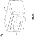
- the RF microwave oven 100a may be implemented and may operate similarly to the RF microwave oven 100 of FIG. 1 , except that the oven cavity 102 of the RF microwave oven 100a may be accessible by a hinged, latched, or sliding door 122, through which meals may be inserted into and removed from the oven cavity.
- the RF module array 108 of the RF microwave oven 100a may be disposed along the top or upper interior surface of the oven cavity 102.
- Heat sinks 118 may similarly be positioned along the upper interior surface at the rear of the oven cavity 102 (e.g., distal to the door 122).
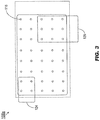
- the RF module array 108a may be implemented and may function identically to the RF module array 108 of FIG. 2B .
- the individual RF modules 116 of the RF module array 108a may be evenly spaced around the upper surface of the oven cavity (102, FIG. 2A ) such that a user may (e.g., via the display/control system 114, FIG. 1 ) adjust the operation of a single RF module 116 or a proximate group of RF modules 124, 126 corresponding to a specific portion or region of the opposing surface of the oven cavity (e.g., the bottom surface).
- the RF microwave oven 100a can adjust individual cooking temperatures and times to optimize the simultaneous cooking of multiple meals including different types of food without overcooking or undercooking any individual components, e.g., by adjusting individual or collective RF modules 116, 124, 126 based on the placement of different food types within the oven cavity 102.
- the RF microwave oven 100a may be programmed (e.g., via the display/control system 114) to simultaneously cook two specific meals or meal components via the grouped RF modules 124, 126. As the meals absorb energy emitted by the grouped RF modules 124, 126, their internal temperatures rise and the meals absorb less energy.
- the RF microwave oven 100a may estimate and monitor the internal temperatures of each meal as it cooks, deactivating one or more RF modules of the group 124 so that the corresponding meal does not overcook.
- systems and methods according to embodiments of the inventive concepts disclosed herein may simplify power management and distribution through, e.g., a galley network controller (GNC) by modulating power requirements of the RF microwave oven to a substantially constant level, as opposed to the full-on/full-off switching associated with magnetron-based units. Further, as this full-on/full-off switching creates a strain on the magnetron (e.g., particularly on its central filament) the operating lifespan of the RF microwave oven may be significantly increased over its magnetron-based counterpart.
- GNC galley network controller
- the individual and group adjustability of RF modules and chips not only eliminates hotspots and coldspots within the oven, but allows the operating frequencies of the RF modules and chips to be tuned to as not to interfere with any RF-based aircraft communications on proximate frequencies.
- the absence of magnetron-specific components such as the stirrer system and waveguides not only reduces weight, but allows for a greater oven cavity volume and capacity for a comparably sized exterior housing.
- embodiments of the methods according to the inventive concepts disclosed herein may include one or more of the steps described herein. Further, such steps may be carried out in any desired order and two or more of the steps may be carried out simultaneously with one another. Two or more of the steps disclosed herein may be combined in a single step, and in some embodiments, one or more of the steps may be carried out as two or more sub-steps. Further, other steps or sub-steps may be carried in addition to, or as substitutes to one or more of the steps disclosed herein.
- inventive concepts disclosed herein are well adapted to carry out the objects and to attain the advantages mentioned herein as well as those inherent in the inventive concepts disclosed herein. While presently preferred embodiments of the inventive concepts disclosed herein have been described for purposes of this disclosure, it will be understood that numerous changes may be made which will readily suggest themselves to those skilled in the art and which are accomplished within the broad scope and coverage of the inventive concepts disclosed and claimed herein.
Landscapes
- Physics & Mathematics (AREA)
- Electromagnetism (AREA)
- Engineering & Computer Science (AREA)
- Aviation & Aerospace Engineering (AREA)
- Chemical & Material Sciences (AREA)
- Combustion & Propulsion (AREA)
- Mechanical Engineering (AREA)
- General Engineering & Computer Science (AREA)
- Electric Ovens (AREA)
- Constitution Of High-Frequency Heating (AREA)
Abstract
Description
- Conventional microwave ovens may be commonly found in aircraft galleys, but there are numerous aircraft-related or aircraft-specific challenges associated with the use of such magnetron-based devices. For example, in order to properly regulate power consumption, the magnetrons must be fully switched on and off. Such power fluctuations not only tax the aircraft's power management and distribution systems, but strain the magnetron itself, adversely affecting its reliability and operating lifespan. Further, magnetron-based microwave cooking requires additional components (e.g., waveguides, stirrer systems for spreading generated radiation, equipment for supplying the magnetron with high-voltage power) that add precious weight and reduce the available space within the oven cavity. Nor is the radiation distribution optimal throughout the oven cavity, resulting in "hotspots" and "coldspots" where food may cook more or less evenly depending upon its placement within the oven. In addition, heat dispersal (e.g., from within the oven cavity) is extremely complicated in a magnetron-generated microwave environment. The heat removal process is complicated further by the lower air pressures associated with aircraft cabins inflight.
- It is therefore an objective of the current invention to provide a microwave oven for an aircraft galley, that has an improved heat control. In one aspect the inventive concepts disclosed herein is directed to a solid-state radio frequency (RF) microwave oven for an aircraft galley. The oven housing is dimensioned to fit within galleys of various sizes and includes a cavity for accommodating food to be heated or cooked. The oven includes an array of spaced or grouped RF emitter modules distributed across the upper interior surface of the oven cavity. One or more RF emitter modules or groups thereof may be selectively programmed to heat a particular meal based on, e.g., its size or composition. As the food cooks, the RF modules detect returned energy unabsorbed by the food, estimating and monitoring the internal temperature of the food and its degree of doneness. The RF microwave oven is connected to the aircraft power supply and includes an oven control module (OCM) in communication with the aircraft galley network or galley network controller. The OCM accepts user input and selectively activates or deactivates one or more of the RF modules depending on the selected meals and their monitored internal temperature. Based on the returned energy detected by the RF modules, the OCM may estimate the internal temperature of a meal and deactivate the appropriate RF modules when a selected meal is done. The OCM modulates the frequency of the RF emitters to avoid interference with communications or other RF-based aircraft systems operating at proximate frequencies.
- Implementations of the inventive concepts disclosed herein may be better understood when consideration is given to the following detailed description thereof. Such description makes reference to the included drawings, which are not necessarily to scale, and in which some features may be exaggerated and some features may be omitted or may be represented schematically in the interest of clarity. Like reference numerals in the drawings may represent and refer to the same or similar element, feature, or function. In the drawings:
-
FIG. 1 is a diagrammatic illustration of an exemplary embodiment of a solid-state RF microwave oven according to the inventive concepts disclosed herein; -
FIGS. 2A and2B are isometric views of the oven ofFIG. 1 ; and -
FIG. 3 illustrates an RF module array of the oven ofFIG. 1 . - Before explaining the inventive concepts disclosed herein in detail, it is to be understood that the inventive concepts are limited by the appended claims ,and are not limited any further in their application to the details of construction and the arrangement of the components or steps or methodologies set forth in the following description or illustrated in the drawings. In the following detailed description of embodiments of the instant inventive concepts, numerous specific details are set forth in order to provide a more thorough understanding of the inventive concepts. However, it will be apparent to one of ordinary skill in the art having the benefit of the instant disclosure that the inventive concepts disclosed herein may be practiced without these specific details. In other instances, well-known features, like the technical concepts of conventional solid state RF microwave ovens, may not be described in detail to avoid unnecessarily complicating the instant disclosure. The inventive concepts disclosed herein are capable of other embodiments or of being practiced or carried out in various ways. Also, it is to be understood that the phraseology and terminology employed herein is for the purpose of description and should not be regarded as limiting.
- As used herein a letter following a reference numeral is intended to reference an embodiment of the feature or element that may be similar, but not necessarily identical, to a previously described element or feature bearing the same reference numeral (e.g., 1, 1a, 1b). Such shorthand notations are used for purposes of convenience only, and should not be construed to limit the inventive concepts disclosed herein in any way unless expressly stated to the contrary.
- Further, unless expressly stated to the contrary, "or" refers to an inclusive or and not to an exclusive or. For example, a condition A or B is satisfied by anyone of the following: A is true (or present) and B is false (or not present), A is false (or not present) and B is true (or present), and both A and B are true (or present).
- In addition, use of the "a" or "an" are employed to describe elements and components of embodiments of the instant inventive concepts. This is done merely for convenience and to give a general sense of the inventive concepts, and "a' and "an" are intended to include one or at least one and the singular also includes the plural unless it is obvious that it is meant otherwise.
- Finally, as used herein any reference to "one embodiment," or "some embodiments" means that a particular element, feature, structure, or characteristic described in connection with the embodiment is included in at least one embodiment of the inventive concepts disclosed herein. The appearances of the phrase "in some embodiments" in various places in the specification are not necessarily all referring to the same embodiment, and embodiments of the inventive concepts disclosed may include one or more of the features expressly described or inherently present herein, or any combination of sub-combination of two or more such features, along with any other features which may not necessarily be expressly described or inherently present in the instant disclosure.
- Broadly, embodiments of the inventive concepts disclosed herein are directed to a solid-state RF-based microwave oven for an aircraft galley. The RF microwave oven saves weight and increases internal capacity by replacing the conventional magnetron with arrays of individually controllable RF emitters that eliminate hotspots and coldspots associated with magnetron-based microwaves. In addition, the RF microwave oven simplifies heat dispersal and provides for simultaneous cooking of multiple means including diverse food types at optimal service times, without undercooking or overcooking individual meal components.
- Referring to
FIG. 1 , an exemplary embodiment of a solid-state radio frequency (RF)microwave oven 100 for an aircraft galley includes anoven cavity 102 set into ahousing 104, an oven control module 106 (OCM), and anRF module array 108 set into an interior surface of theoven cavity 102. For example, theRF module array 108 may be set into the upper or top surface of theoven cavity 102. Thehousing 104 is externally dimensioned to fit galley of anaircraft 110, e.g., as a standalone device or as a galley insert (GAIN). The OCM 106 may be connected to one or more aircraft networks via acontroller 110a associated with the aircraft galley, i.e. agalley network controller 110a (GNC), which may monitor and manage power distribution to, and consumption by, theRF microwave oven 100. For example, theRF module array 108 may be connected to, and powered by, anaircraft power supply 112 providing low-voltage to the RF modules. However, unlike magnetron-based microwave ovens, theRF microwave oven 100 may not require additional equipment to provide the high-voltage power supply needed for magnetron operations. The OCM 106 may include protection circuits as well as acontrol processor 114, or a display/control subsystem 114 for controlling the operation of theRF module array 108. The display/control subsystem 114 may include a display screen or like surface on the exterior surface of thehousing 104 and a keypad, touchscreen, or similar means of accepting control input from a user. For example, the user may indicate the type or volume of food/s to be cooked, from which theOCM 106 may infer an appropriate cooking time and intensity (e.g., how manyindividual RF modules 116 of theRF module array 108 are to be activated, such as the RF modules corresponding to a desired portion of the oven cavity 102). The OCM 106 may use this information to monitor the internal temperature of the food (e.g., based on returned energy emitted by theRF modules 116 but unabsorbed by the food) in order to determine whether cooking is complete. - Each
individual RF module 116 includes one or more RF emitters, or "chips" 116a. For example, each RF "chip" 116a may be a closed-loop RF emitter incorporating oscillators (116b),amplifiers 116c, anddirectional couplers 116d optimized for ideal emission frequency and phase. For example, the transmission of theRF chips 116a may be tuned so as not to interfere with aircraft wireless communications (e.g., 2.4 GHz aircraft WiFi) or other RF devices operating onboard the aircraft. Different combinations ofRF chips 116a orRF modules 116 may be simultaneously adjusted for fine control over the cooking of multiple and diverse foods at once. - The
RF microwave oven 100 includes one ormore heat sinks 118 for dissipatingheat 118a generated within theoven cavity 102 by the operation of the oven. For example, theheat sinks 118 may include fans within theoven cavity 102 for circulating air over theRF module array 108 and through exhaust outlets (not shown) within theoven cavity 102. Alternatively, theheat sinks 118 may include water-cooled or liquid-cooled systems by which heat within theoven cavity 102 is transferred to fluids circulated through the cavity and removed from the circulated fluid external to thehousing 104. - In some embodiments, the
RF microwave oven 100 may be a multimode oven incorporatinginternal heating elements 120 in addition to theRF module array 108. For example, meals may be heated via theRF module array 108 or via theheating element 120, or by sequential application of both RF modules and the heating element. Theheating element 120 may be disposed within theoven cavity 102 and include a fan (not shown) for circulating the heated air throughout the cavity interior. - Referring now to
FIGS. 2A and2B , theRF microwave oven 100a may be implemented and may operate similarly to theRF microwave oven 100 ofFIG. 1 , except that theoven cavity 102 of theRF microwave oven 100a may be accessible by a hinged, latched, or slidingdoor 122, through which meals may be inserted into and removed from the oven cavity. For example, theRF module array 108 of theRF microwave oven 100a may be disposed along the top or upper interior surface of theoven cavity 102. Heat sinks 118 may similarly be positioned along the upper interior surface at the rear of the oven cavity 102 (e.g., distal to the door 122). - Referring to
FIG. 3 , theRF module array 108a may be implemented and may function identically to theRF module array 108 ofFIG. 2B . Theindividual RF modules 116 of theRF module array 108a may be evenly spaced around the upper surface of the oven cavity (102,FIG. 2A ) such that a user may (e.g., via the display/control system 114,FIG. 1 ) adjust the operation of asingle RF module 116 or a proximate group ofRF modules RF microwave oven 100a can adjust individual cooking temperatures and times to optimize the simultaneous cooking of multiple meals including different types of food without overcooking or undercooking any individual components, e.g., by adjusting individual orcollective RF modules oven cavity 102. For example, theRF microwave oven 100a may be programmed (e.g., via the display/control system 114) to simultaneously cook two specific meals or meal components via the groupedRF modules RF modules RF modules RF microwave oven 100a may estimate and monitor the internal temperatures of each meal as it cooks, deactivating one or more RF modules of thegroup 124 so that the corresponding meal does not overcook. - As will be appreciated from the above, systems and methods according to embodiments of the inventive concepts disclosed herein may simplify power management and distribution through, e.g., a galley network controller (GNC) by modulating power requirements of the RF microwave oven to a substantially constant level, as opposed to the full-on/full-off switching associated with magnetron-based units. Further, as this full-on/full-off switching creates a strain on the magnetron (e.g., particularly on its central filament) the operating lifespan of the RF microwave oven may be significantly increased over its magnetron-based counterpart. In addition, the individual and group adjustability of RF modules and chips not only eliminates hotspots and coldspots within the oven, but allows the operating frequencies of the RF modules and chips to be tuned to as not to interfere with any RF-based aircraft communications on proximate frequencies. Finally, the absence of magnetron-specific components such as the stirrer system and waveguides not only reduces weight, but allows for a greater oven cavity volume and capacity for a comparably sized exterior housing.
- It is to be understood that embodiments of the methods according to the inventive concepts disclosed herein may include one or more of the steps described herein. Further, such steps may be carried out in any desired order and two or more of the steps may be carried out simultaneously with one another. Two or more of the steps disclosed herein may be combined in a single step, and in some embodiments, one or more of the steps may be carried out as two or more sub-steps. Further, other steps or sub-steps may be carried in addition to, or as substitutes to one or more of the steps disclosed herein.
- From the above description, it is clear that the inventive concepts disclosed herein are well adapted to carry out the objects and to attain the advantages mentioned herein as well as those inherent in the inventive concepts disclosed herein. While presently preferred embodiments of the inventive concepts disclosed herein have been described for purposes of this disclosure, it will be understood that numerous changes may be made which will readily suggest themselves to those skilled in the art and which are accomplished within the broad scope and coverage of the inventive concepts disclosed and claimed herein.
Claims (7)
- A solid-state radio frequency (RF) microwave oven (100, 100a) for an aircraft galley, comprising:a housing (104) dimensioned to fit an aircraft galley;a cavity (102) set within the housing, the cavity (102) capable of accommodating food to be heated;an array (108, 108a, 124, 126) of RF modules (116) disposed on a first interior surface of the cavity (102) in a spaced apart relationship, each RF module (116) comprising one or more RF emitters (116a)configured to:heat food accommodated in the cavity (102) by emitting at least one RF signal at a first frequency; anddetect returned energy based on the emitted RF signal and associated with food accommodated in the cavity (102);a power source coupled to the array (108, 104a, 124, 126) of RF modules (116) and configured to be coupled to a power supply (112) of the aircraft;at least one heat sink (118) coupled to one or more of the first interior surface and a second interior surface of the cavity (102), the heat sink (118) configured to remove heat from the cavity (102); andan oven control module (OCM) (106) coupled to the array (108, 108a, 124, 126) of RF modules (116) and configured to be coupled to a controller (110a) associated with the aircraft galley, the OCM including at least one control processor (114) configured to:accept control input from a user;estimate at least one temperature of food accommodated in the cavity (102) based on the detected returned energy;selectively activate one or more first RF modules of the array (108, 108a, 124, 126) of RF modules based on at least one of the control input and the estimated temperature; andmodulate the at least one first frequency.
- The solid-state RF microwave oven according to claim 1, wherein the at least one heat sink (118) includes at least one first fan disposed within the cavity (102) and configured to circulate air over the array of RF modules (108, 108a, 124, 126).
- The solid-state RF microwave oven according to claim 1 or 2, wherein the at least one heat sink (118) includes at least one coolant circulation system including one or more pipes configured to circulate a liquid coolant into the cavity (102) and through the outlets.
- The solid-state RF microwave oven according to one or more of claims 1-3, wherein:the one or more first RF modules are associated with a first portion of a bottom surface of the cavity (102); andone or more second RF modules are associated with at least one second portion of the bottom surface.
- The solid-state RF microwave oven according to one or more of claims 1-4, further comprising:at least one control unit coupled to an exterior surface of the housing and to the OCM, the control unit including at least one of:
a display surface configured to display at least one state of the microwave oven (100, 100a); anda touch-sensitive surface configured to receive the control input from the user. - The solid-state RF microwave oven according to one or more of claims 1-5, further comprising:at least one auxiliary heating element disposed within the cavity and coupled to the power source; andat least one second fan disposed within the cavity (102) and configured to heat the cavity (102) by circulating air over the auxiliary heating element.
- An aircraft galley comprising a solid-state RF microwave oven according to one or more of the claims 1-6, the control module (OCM) (106) of the micro wave oven being coupled to a controller (110a) associated with the aircraft galley.
Applications Claiming Priority (1)
| Application Number | Priority Date | Filing Date | Title |
|---|---|---|---|
| US15/946,636 US10939511B2 (en) | 2018-04-05 | 2018-04-05 | Solid state radio frequency (SSRF) microwave oven for aircraft galley |
Publications (2)
| Publication Number | Publication Date |
|---|---|
| EP3549862A1 true EP3549862A1 (en) | 2019-10-09 |
| EP3549862B1 EP3549862B1 (en) | 2022-08-10 |
Family
ID=66101898
Family Applications (1)
| Application Number | Title | Priority Date | Filing Date |
|---|---|---|---|
| EP19167501.6A Active EP3549862B1 (en) | 2018-04-05 | 2019-04-05 | Solid state radio frequency (ssrf) microwave oven for aircraft galley |
Country Status (3)
| Country | Link |
|---|---|
| US (1) | US10939511B2 (en) |
| EP (1) | EP3549862B1 (en) |
| CN (1) | CN110351917B (en) |
Families Citing this family (5)
| Publication number | Priority date | Publication date | Assignee | Title |
|---|---|---|---|---|
| EP3707962A4 (en) * | 2017-11-06 | 2021-12-08 | Brava Home, Inc. | SPECTRAL POWER DENSITY CONFIGURATION IN A COOKING APPLIANCE |
| US11401036B2 (en) * | 2020-01-17 | 2022-08-02 | Koninklijke Fabriek Inventum B.V. | Titanium inner shell for electrical galley inserts |
| CN113310210A (en) * | 2020-02-06 | 2021-08-27 | 皇家工厂有限公司 | Solid State Radio Frequency (SSRF) water heater apparatus |
| EP4415197A1 (en) * | 2023-02-09 | 2024-08-14 | B/E Aerospace, Inc. | High voltage direct current powered aircraft appliances |
| EP4549319A1 (en) * | 2023-10-31 | 2025-05-07 | B/E Aerospace, Inc. | Tilt protection for aircraft galley inserts |
Citations (6)
| Publication number | Priority date | Publication date | Assignee | Title |
|---|---|---|---|---|
| US3692968A (en) * | 1970-04-06 | 1972-09-19 | Sanyo Electric Co | Electronic oven |
| US5558800A (en) * | 1995-06-19 | 1996-09-24 | Northrop Grumman | Microwave power radiator for microwave heating applications |
| US6462320B1 (en) * | 1996-05-17 | 2002-10-08 | Technology Finance Corporation (Proprietary) Limited | Dielectric heating device employing microwave heating for heating or cooking substances |
| US20120111856A1 (en) * | 2009-07-10 | 2012-05-10 | Panasonic Corporation | Microwave heating device and microwave heating control method |
| US20160192446A1 (en) * | 2014-06-18 | 2016-06-30 | Kareem Sameh SEDDIK | System, method, and process for selective heating of materials in an electromagnetic oven |
| US20170240295A1 (en) * | 2016-02-19 | 2017-08-24 | The Boeing Company | Real time galley power management and fault monitoring system |
Family Cites Families (12)
| Publication number | Priority date | Publication date | Assignee | Title |
|---|---|---|---|---|
| FR2786222B1 (en) * | 1998-11-19 | 2000-12-29 | Snecma | LAMELLE SEALING DEVICE |
| US7498549B2 (en) | 2003-10-24 | 2009-03-03 | Raytheon Company | Selective layer millimeter-wave surface-heating system and method |
| US8839527B2 (en) | 2006-02-21 | 2014-09-23 | Goji Limited | Drying apparatus and methods and accessories for use therewith |
| EP2528414B1 (en) | 2006-02-21 | 2016-05-11 | Goji Limited | Electromagnetic heating |
| ES2533575T3 (en) | 2006-07-10 | 2015-04-13 | Goji Limited | Method and system for multifrequency microwave heating |
| US9131543B2 (en) | 2007-08-30 | 2015-09-08 | Goji Limited | Dynamic impedance matching in RF resonator cavity |
| KR101663449B1 (en) | 2009-11-10 | 2016-10-06 | 고지 엘티디. | Device and method for controlling energy |
| US9161390B2 (en) | 2012-02-06 | 2015-10-13 | Goji Limited | Methods and devices for applying RF energy according to energy application schedules |
| US9301344B2 (en) | 2012-05-24 | 2016-03-29 | Goji Limited | RF energy application based on absorption peaks |
| CN103912900A (en) * | 2014-03-20 | 2014-07-09 | 广东美的厨房电器制造有限公司 | Semiconductor microwave generator connection structure of microwave oven and microwave oven |
| DE102016114708B4 (en) | 2016-08-09 | 2020-06-10 | Miele & Cie. Kg | Method for operating a cooking device |
| CN106225029A (en) * | 2016-08-25 | 2016-12-14 | 陈鹏 | A kind of solid state microwave power source and use the solid state microwave stove in this solid state microwave power source |
-
2018
- 2018-04-05 US US15/946,636 patent/US10939511B2/en active Active
-
2019
- 2019-04-01 CN CN201910256451.4A patent/CN110351917B/en active Active
- 2019-04-05 EP EP19167501.6A patent/EP3549862B1/en active Active
Patent Citations (6)
| Publication number | Priority date | Publication date | Assignee | Title |
|---|---|---|---|---|
| US3692968A (en) * | 1970-04-06 | 1972-09-19 | Sanyo Electric Co | Electronic oven |
| US5558800A (en) * | 1995-06-19 | 1996-09-24 | Northrop Grumman | Microwave power radiator for microwave heating applications |
| US6462320B1 (en) * | 1996-05-17 | 2002-10-08 | Technology Finance Corporation (Proprietary) Limited | Dielectric heating device employing microwave heating for heating or cooking substances |
| US20120111856A1 (en) * | 2009-07-10 | 2012-05-10 | Panasonic Corporation | Microwave heating device and microwave heating control method |
| US20160192446A1 (en) * | 2014-06-18 | 2016-06-30 | Kareem Sameh SEDDIK | System, method, and process for selective heating of materials in an electromagnetic oven |
| US20170240295A1 (en) * | 2016-02-19 | 2017-08-24 | The Boeing Company | Real time galley power management and fault monitoring system |
Also Published As
| Publication number | Publication date |
|---|---|
| EP3549862B1 (en) | 2022-08-10 |
| US20190313486A1 (en) | 2019-10-10 |
| US10939511B2 (en) | 2021-03-02 |
| CN110351917A (en) | 2019-10-18 |
| CN110351917B (en) | 2022-10-18 |
Similar Documents
| Publication | Publication Date | Title |
|---|---|---|
| EP3549862B1 (en) | Solid state radio frequency (ssrf) microwave oven for aircraft galley | |
| EP1676465B1 (en) | Speed cooking oven with slotted microwave antenna | |
| RU2456779C2 (en) | Microwave heating apparatus | |
| US9769884B2 (en) | Versatile microwave heating apparatus | |
| KR101709473B1 (en) | A Cooking apparatus using microwave | |
| EP3761836B1 (en) | Combined apparatus for heating, cooking, grilling and defrosting of various kinds of food | |
| US20150136760A1 (en) | Microwave oven using solid state amplifiers and antenna array | |
| EP3525550B1 (en) | Microwave heating device and method for operating a microwave heating device | |
| WO2019055476A2 (en) | High-power solid-state microwave generator for rf energy applications | |
| US20160183332A1 (en) | Microwave generator and microwave oven | |
| WO1999052327A1 (en) | Apparatus for supplying microwave energy to a cavity | |
| EP3298861B1 (en) | Apparatus for providing customizable heat zones in an oven | |
| JP7055822B2 (en) | Microwave cooker, control method and storage medium | |
| EP3713375B1 (en) | Rf heating apparatus with re-radiators | |
| US11627645B2 (en) | Microwave heating device and method for operating a microwave heating device | |
| US3527915A (en) | No load sensing device for microwave ovens | |
| GB1172918A (en) | Microwave Ovens and Methods of Cooking Food | |
| KR20190116381A (en) | Integrated temperature control and method for multilayer ceramic | |
| KR101759160B1 (en) | A cooking apparatus and method for operating the same | |
| KR101123359B1 (en) | Apparatus of oven having variable boil space for cooking at the same time | |
| EP3476183B1 (en) | Multi-feed microwave oven with improved crisp function | |
| CN109417840B (en) | RF Power Control System and Method for Waveguide of Microwave Oven with Multiple Feed Ports | |
| US10827569B2 (en) | Crispness and browning in full flat microwave oven | |
| KR102141137B1 (en) | Oven with heating loop antenna | |
| KR102805315B1 (en) | Cooking apparatus and method for controlling thereof |
Legal Events
| Date | Code | Title | Description |
|---|---|---|---|
| PUAI | Public reference made under article 153(3) epc to a published international application that has entered the european phase |
Free format text: ORIGINAL CODE: 0009012 |
|
| STAA | Information on the status of an ep patent application or granted ep patent |
Free format text: STATUS: THE APPLICATION HAS BEEN PUBLISHED |
|
| AK | Designated contracting states |
Kind code of ref document: A1 Designated state(s): AL AT BE BG CH CY CZ DE DK EE ES FI FR GB GR HR HU IE IS IT LI LT LU LV MC MK MT NL NO PL PT RO RS SE SI SK SM TR |
|
| AX | Request for extension of the european patent |
Extension state: BA ME |
|
| STAA | Information on the status of an ep patent application or granted ep patent |
Free format text: STATUS: REQUEST FOR EXAMINATION WAS MADE |
|
| 17P | Request for examination filed |
Effective date: 20200406 |
|
| RBV | Designated contracting states (corrected) |
Designated state(s): AL AT BE BG CH CY CZ DE DK EE ES FI FR GB GR HR HU IE IS IT LI LT LU LV MC MK MT NL NO PL PT RO RS SE SI SK SM TR |
|
| STAA | Information on the status of an ep patent application or granted ep patent |
Free format text: STATUS: EXAMINATION IS IN PROGRESS |
|
| 17Q | First examination report despatched |
Effective date: 20200701 |
|
| GRAP | Despatch of communication of intention to grant a patent |
Free format text: ORIGINAL CODE: EPIDOSNIGR1 |
|
| STAA | Information on the status of an ep patent application or granted ep patent |
Free format text: STATUS: GRANT OF PATENT IS INTENDED |
|
| INTG | Intention to grant announced |
Effective date: 20220330 |
|
| GRAS | Grant fee paid |
Free format text: ORIGINAL CODE: EPIDOSNIGR3 |
|
| GRAA | (expected) grant |
Free format text: ORIGINAL CODE: 0009210 |
|
| STAA | Information on the status of an ep patent application or granted ep patent |
Free format text: STATUS: THE PATENT HAS BEEN GRANTED |
|
| AK | Designated contracting states |
Kind code of ref document: B1 Designated state(s): AL AT BE BG CH CY CZ DE DK EE ES FI FR GB GR HR HU IE IS IT LI LT LU LV MC MK MT NL NO PL PT RO RS SE SI SK SM TR |
|
| REG | Reference to a national code |
Ref country code: AT Ref legal event code: REF Ref document number: 1510377 Country of ref document: AT Kind code of ref document: T Effective date: 20220815 Ref country code: CH Ref legal event code: EP |
|
| REG | Reference to a national code |
Ref country code: IE Ref legal event code: FG4D |
|
| REG | Reference to a national code |
Ref country code: DE Ref legal event code: R096 Ref document number: 602019017961 Country of ref document: DE |
|
| REG | Reference to a national code |
Ref country code: NL Ref legal event code: MP Effective date: 20220810 |
|
| REG | Reference to a national code |
Ref country code: LT Ref legal event code: MG9D |
|
| PG25 | Lapsed in a contracting state [announced via postgrant information from national office to epo] |
Ref country code: SE Free format text: LAPSE BECAUSE OF FAILURE TO SUBMIT A TRANSLATION OF THE DESCRIPTION OR TO PAY THE FEE WITHIN THE PRESCRIBED TIME-LIMIT Effective date: 20220810 Ref country code: RS Free format text: LAPSE BECAUSE OF FAILURE TO SUBMIT A TRANSLATION OF THE DESCRIPTION OR TO PAY THE FEE WITHIN THE PRESCRIBED TIME-LIMIT Effective date: 20220810 Ref country code: PT Free format text: LAPSE BECAUSE OF FAILURE TO SUBMIT A TRANSLATION OF THE DESCRIPTION OR TO PAY THE FEE WITHIN THE PRESCRIBED TIME-LIMIT Effective date: 20221212 Ref country code: NO Free format text: LAPSE BECAUSE OF FAILURE TO SUBMIT A TRANSLATION OF THE DESCRIPTION OR TO PAY THE FEE WITHIN THE PRESCRIBED TIME-LIMIT Effective date: 20221110 Ref country code: NL Free format text: LAPSE BECAUSE OF FAILURE TO SUBMIT A TRANSLATION OF THE DESCRIPTION OR TO PAY THE FEE WITHIN THE PRESCRIBED TIME-LIMIT Effective date: 20220810 Ref country code: LV Free format text: LAPSE BECAUSE OF FAILURE TO SUBMIT A TRANSLATION OF THE DESCRIPTION OR TO PAY THE FEE WITHIN THE PRESCRIBED TIME-LIMIT Effective date: 20220810 Ref country code: LT Free format text: LAPSE BECAUSE OF FAILURE TO SUBMIT A TRANSLATION OF THE DESCRIPTION OR TO PAY THE FEE WITHIN THE PRESCRIBED TIME-LIMIT Effective date: 20220810 Ref country code: FI Free format text: LAPSE BECAUSE OF FAILURE TO SUBMIT A TRANSLATION OF THE DESCRIPTION OR TO PAY THE FEE WITHIN THE PRESCRIBED TIME-LIMIT Effective date: 20220810 |
|
| REG | Reference to a national code |
Ref country code: AT Ref legal event code: MK05 Ref document number: 1510377 Country of ref document: AT Kind code of ref document: T Effective date: 20220810 |
|
| PG25 | Lapsed in a contracting state [announced via postgrant information from national office to epo] |
Ref country code: PL Free format text: LAPSE BECAUSE OF FAILURE TO SUBMIT A TRANSLATION OF THE DESCRIPTION OR TO PAY THE FEE WITHIN THE PRESCRIBED TIME-LIMIT Effective date: 20220810 Ref country code: IS Free format text: LAPSE BECAUSE OF FAILURE TO SUBMIT A TRANSLATION OF THE DESCRIPTION OR TO PAY THE FEE WITHIN THE PRESCRIBED TIME-LIMIT Effective date: 20221210 Ref country code: HR Free format text: LAPSE BECAUSE OF FAILURE TO SUBMIT A TRANSLATION OF THE DESCRIPTION OR TO PAY THE FEE WITHIN THE PRESCRIBED TIME-LIMIT Effective date: 20220810 Ref country code: GR Free format text: LAPSE BECAUSE OF FAILURE TO SUBMIT A TRANSLATION OF THE DESCRIPTION OR TO PAY THE FEE WITHIN THE PRESCRIBED TIME-LIMIT Effective date: 20221111 |
|
| PG25 | Lapsed in a contracting state [announced via postgrant information from national office to epo] |
Ref country code: SM Free format text: LAPSE BECAUSE OF FAILURE TO SUBMIT A TRANSLATION OF THE DESCRIPTION OR TO PAY THE FEE WITHIN THE PRESCRIBED TIME-LIMIT Effective date: 20220810 Ref country code: RO Free format text: LAPSE BECAUSE OF FAILURE TO SUBMIT A TRANSLATION OF THE DESCRIPTION OR TO PAY THE FEE WITHIN THE PRESCRIBED TIME-LIMIT Effective date: 20220810 Ref country code: ES Free format text: LAPSE BECAUSE OF FAILURE TO SUBMIT A TRANSLATION OF THE DESCRIPTION OR TO PAY THE FEE WITHIN THE PRESCRIBED TIME-LIMIT Effective date: 20220810 Ref country code: DK Free format text: LAPSE BECAUSE OF FAILURE TO SUBMIT A TRANSLATION OF THE DESCRIPTION OR TO PAY THE FEE WITHIN THE PRESCRIBED TIME-LIMIT Effective date: 20220810 Ref country code: CZ Free format text: LAPSE BECAUSE OF FAILURE TO SUBMIT A TRANSLATION OF THE DESCRIPTION OR TO PAY THE FEE WITHIN THE PRESCRIBED TIME-LIMIT Effective date: 20220810 Ref country code: AT Free format text: LAPSE BECAUSE OF FAILURE TO SUBMIT A TRANSLATION OF THE DESCRIPTION OR TO PAY THE FEE WITHIN THE PRESCRIBED TIME-LIMIT Effective date: 20220810 |
|
| REG | Reference to a national code |
Ref country code: DE Ref legal event code: R097 Ref document number: 602019017961 Country of ref document: DE |
|
| PG25 | Lapsed in a contracting state [announced via postgrant information from national office to epo] |
Ref country code: SK Free format text: LAPSE BECAUSE OF FAILURE TO SUBMIT A TRANSLATION OF THE DESCRIPTION OR TO PAY THE FEE WITHIN THE PRESCRIBED TIME-LIMIT Effective date: 20220810 Ref country code: EE Free format text: LAPSE BECAUSE OF FAILURE TO SUBMIT A TRANSLATION OF THE DESCRIPTION OR TO PAY THE FEE WITHIN THE PRESCRIBED TIME-LIMIT Effective date: 20220810 |
|
| PLBE | No opposition filed within time limit |
Free format text: ORIGINAL CODE: 0009261 |
|
| STAA | Information on the status of an ep patent application or granted ep patent |
Free format text: STATUS: NO OPPOSITION FILED WITHIN TIME LIMIT |
|
| PG25 | Lapsed in a contracting state [announced via postgrant information from national office to epo] |
Ref country code: AL Free format text: LAPSE BECAUSE OF FAILURE TO SUBMIT A TRANSLATION OF THE DESCRIPTION OR TO PAY THE FEE WITHIN THE PRESCRIBED TIME-LIMIT Effective date: 20220810 |
|
| P01 | Opt-out of the competence of the unified patent court (upc) registered |
Effective date: 20230606 |
|
| 26N | No opposition filed |
Effective date: 20230511 |
|
| PG25 | Lapsed in a contracting state [announced via postgrant information from national office to epo] |
Ref country code: SI Free format text: LAPSE BECAUSE OF FAILURE TO SUBMIT A TRANSLATION OF THE DESCRIPTION OR TO PAY THE FEE WITHIN THE PRESCRIBED TIME-LIMIT Effective date: 20220810 |
|
| REG | Reference to a national code |
Ref country code: CH Ref legal event code: PL |
|
| PG25 | Lapsed in a contracting state [announced via postgrant information from national office to epo] |
Ref country code: LU Free format text: LAPSE BECAUSE OF NON-PAYMENT OF DUE FEES Effective date: 20230405 |
|
| REG | Reference to a national code |
Ref country code: BE Ref legal event code: MM Effective date: 20230430 |
|
| PG25 | Lapsed in a contracting state [announced via postgrant information from national office to epo] |
Ref country code: MC Free format text: LAPSE BECAUSE OF FAILURE TO SUBMIT A TRANSLATION OF THE DESCRIPTION OR TO PAY THE FEE WITHIN THE PRESCRIBED TIME-LIMIT Effective date: 20220810 |
|
| PG25 | Lapsed in a contracting state [announced via postgrant information from national office to epo] |
Ref country code: MC Free format text: LAPSE BECAUSE OF FAILURE TO SUBMIT A TRANSLATION OF THE DESCRIPTION OR TO PAY THE FEE WITHIN THE PRESCRIBED TIME-LIMIT Effective date: 20220810 Ref country code: LI Free format text: LAPSE BECAUSE OF NON-PAYMENT OF DUE FEES Effective date: 20230430 Ref country code: CH Free format text: LAPSE BECAUSE OF NON-PAYMENT OF DUE FEES Effective date: 20230430 |
|
| REG | Reference to a national code |
Ref country code: IE Ref legal event code: MM4A |
|
| PG25 | Lapsed in a contracting state [announced via postgrant information from national office to epo] |
Ref country code: BE Free format text: LAPSE BECAUSE OF NON-PAYMENT OF DUE FEES Effective date: 20230430 |
|
| PG25 | Lapsed in a contracting state [announced via postgrant information from national office to epo] |
Ref country code: IE Free format text: LAPSE BECAUSE OF NON-PAYMENT OF DUE FEES Effective date: 20230405 |
|
| PG25 | Lapsed in a contracting state [announced via postgrant information from national office to epo] |
Ref country code: IE Free format text: LAPSE BECAUSE OF NON-PAYMENT OF DUE FEES Effective date: 20230405 |
|
| PG25 | Lapsed in a contracting state [announced via postgrant information from national office to epo] |
Ref country code: IT Free format text: LAPSE BECAUSE OF FAILURE TO SUBMIT A TRANSLATION OF THE DESCRIPTION OR TO PAY THE FEE WITHIN THE PRESCRIBED TIME-LIMIT Effective date: 20220810 |
|
| PG25 | Lapsed in a contracting state [announced via postgrant information from national office to epo] |
Ref country code: BG Free format text: LAPSE BECAUSE OF FAILURE TO SUBMIT A TRANSLATION OF THE DESCRIPTION OR TO PAY THE FEE WITHIN THE PRESCRIBED TIME-LIMIT Effective date: 20220810 |
|
| PG25 | Lapsed in a contracting state [announced via postgrant information from national office to epo] |
Ref country code: BG Free format text: LAPSE BECAUSE OF FAILURE TO SUBMIT A TRANSLATION OF THE DESCRIPTION OR TO PAY THE FEE WITHIN THE PRESCRIBED TIME-LIMIT Effective date: 20220810 |
|
| PGFP | Annual fee paid to national office [announced via postgrant information from national office to epo] |
Ref country code: DE Payment date: 20250319 Year of fee payment: 7 |
|
| PG25 | Lapsed in a contracting state [announced via postgrant information from national office to epo] |
Ref country code: CY Free format text: LAPSE BECAUSE OF FAILURE TO SUBMIT A TRANSLATION OF THE DESCRIPTION OR TO PAY THE FEE WITHIN THE PRESCRIBED TIME-LIMIT; INVALID AB INITIO Effective date: 20190405 |
|
| PG25 | Lapsed in a contracting state [announced via postgrant information from national office to epo] |
Ref country code: HU Free format text: LAPSE BECAUSE OF FAILURE TO SUBMIT A TRANSLATION OF THE DESCRIPTION OR TO PAY THE FEE WITHIN THE PRESCRIBED TIME-LIMIT; INVALID AB INITIO Effective date: 20190405 |
|
| PG25 | Lapsed in a contracting state [announced via postgrant information from national office to epo] |
Ref country code: TR Free format text: LAPSE BECAUSE OF FAILURE TO SUBMIT A TRANSLATION OF THE DESCRIPTION OR TO PAY THE FEE WITHIN THE PRESCRIBED TIME-LIMIT Effective date: 20220810 |
|
| PGFP | Annual fee paid to national office [announced via postgrant information from national office to epo] |
Ref country code: GB Payment date: 20260319 Year of fee payment: 8 |
|
| PGFP | Annual fee paid to national office [announced via postgrant information from national office to epo] |
Ref country code: FR Payment date: 20260320 Year of fee payment: 8 |