EP3549807A1 - Pointer device for an indicator instrument, in particular for a vehicle - Google Patents
Pointer device for an indicator instrument, in particular for a vehicle Download PDFInfo
- Publication number
- EP3549807A1 EP3549807A1 EP19167655.0A EP19167655A EP3549807A1 EP 3549807 A1 EP3549807 A1 EP 3549807A1 EP 19167655 A EP19167655 A EP 19167655A EP 3549807 A1 EP3549807 A1 EP 3549807A1
- Authority
- EP
- European Patent Office
- Prior art keywords
- light
- hub
- cap
- pointer
- radially
- Prior art date
- Legal status (The legal status is an assumption and is not a legal conclusion. Google has not performed a legal analysis and makes no representation as to the accuracy of the status listed.)
- Granted
Links
- 230000005540 biological transmission Effects 0.000 claims abstract description 11
- 238000005304 joining Methods 0.000 claims abstract description 5
- 239000000463 material Substances 0.000 claims description 16
- 239000011248 coating agent Substances 0.000 description 8
- 238000000576 coating method Methods 0.000 description 8
- 230000003287 optical effect Effects 0.000 description 6
- 238000000465 moulding Methods 0.000 description 4
- 230000000903 blocking effect Effects 0.000 description 3
- 125000001475 halogen functional group Chemical group 0.000 description 3
- 238000004519 manufacturing process Methods 0.000 description 3
- 230000000295 complement effect Effects 0.000 description 2
- 239000006185 dispersion Substances 0.000 description 2
- 230000007480 spreading Effects 0.000 description 2
- 238000003892 spreading Methods 0.000 description 2
- 239000011358 absorbing material Substances 0.000 description 1
- 230000009102 absorption Effects 0.000 description 1
- 238000010521 absorption reaction Methods 0.000 description 1
- 230000009471 action Effects 0.000 description 1
- 230000004075 alteration Effects 0.000 description 1
- 230000015572 biosynthetic process Effects 0.000 description 1
- 239000007894 caplet Substances 0.000 description 1
- 230000008878 coupling Effects 0.000 description 1
- 238000010168 coupling process Methods 0.000 description 1
- 238000005859 coupling reaction Methods 0.000 description 1
- 238000001914 filtration Methods 0.000 description 1
- 238000000034 method Methods 0.000 description 1
- 238000007639 printing Methods 0.000 description 1
- 238000007650 screen-printing Methods 0.000 description 1
Images


Classifications
-
- B—PERFORMING OPERATIONS; TRANSPORTING
- B60—VEHICLES IN GENERAL
- B60K—ARRANGEMENT OR MOUNTING OF PROPULSION UNITS OR OF TRANSMISSIONS IN VEHICLES; ARRANGEMENT OR MOUNTING OF PLURAL DIVERSE PRIME-MOVERS IN VEHICLES; AUXILIARY DRIVES FOR VEHICLES; INSTRUMENTATION OR DASHBOARDS FOR VEHICLES; ARRANGEMENTS IN CONNECTION WITH COOLING, AIR INTAKE, GAS EXHAUST OR FUEL SUPPLY OF PROPULSION UNITS IN VEHICLES
- B60K35/00—Arrangement of adaptations of instruments
-
- G—PHYSICS
- G01—MEASURING; TESTING
- G01D—MEASURING NOT SPECIALLY ADAPTED FOR A SPECIFIC VARIABLE; ARRANGEMENTS FOR MEASURING TWO OR MORE VARIABLES NOT COVERED IN A SINGLE OTHER SUBCLASS; TARIFF METERING APPARATUS; MEASURING OR TESTING NOT OTHERWISE PROVIDED FOR
- G01D13/00—Component parts of indicators for measuring arrangements not specially adapted for a specific variable
- G01D13/22—Pointers, e.g. settable pointer
- G01D13/26—Pointers, e.g. settable pointer adapted to perform a further operation, e.g. making electrical contact
- G01D13/265—Pointers which conduct light
-
- B60K35/60—
-
- G—PHYSICS
- G01—MEASURING; TESTING
- G01D—MEASURING NOT SPECIALLY ADAPTED FOR A SPECIFIC VARIABLE; ARRANGEMENTS FOR MEASURING TWO OR MORE VARIABLES NOT COVERED IN A SINGLE OTHER SUBCLASS; TARIFF METERING APPARATUS; MEASURING OR TESTING NOT OTHERWISE PROVIDED FOR
- G01D13/00—Component parts of indicators for measuring arrangements not specially adapted for a specific variable
- G01D13/22—Pointers, e.g. settable pointer
- G01D13/28—Pointers, e.g. settable pointer with luminescent markings
-
- B60K2360/20—
-
- B60K2360/336—
-
- B60K2360/693—
-
- B60K2360/698—
-
- B60K2360/6992—
Definitions
- the invention relates to a pointer device for an indicator instrument, in particular for a vehicle.
- automotive dashboards are provided with indicator instruments to give numerical items of information to the driver, for example items of information concerning the speed of the vehicle and the revolutions per minute of the thermal engine.
- These instruments are generally provided with a dial having a series of marks and/or numbers and with a rotary pointer device having a body made of a light-guide material.
- This body comprises a hub, which is hinged about an axis so as to rotate due to the action of a motor, and a pointer, which radially protrudes from the hub so as to indicate the mark or the number corresponding to the item of information to be given to the driver.
- the front face of the pointer is luminous, at least under night driving conditions, thanks to one or more light sources arranged close to the hub under the dial.
- patent EP0967465 discloses a cap fitted on the hub and a shield, which covers the hub at the bottom so as to avoid the formation of light halos on the dial.
- the cap is entirely opaque, so that it completely prevents light from spreading towards the driver in the area of the hub of the light-guide body.
- the cap is overmoulded on the hub, so as to form one single piece with the latter, and has a protuberance, which engages a recess obtained in the light-guide material of the hub. In this case, again, the cap prevents light from spreading towards the driver in the area of the hub of the light-guide body.
- EP3187834 relates to two different solutions, wherein the cap lets the light flow towards the driver, namely defines a lightable area which, in particular, has a circular shape.
- the cap consists of two distinct and separate pieces defining the outer perimeter and the inner perimeter, respectively, of the lightable source. This solution is scarcely satisfying, as the number of components of the pointer device is larger.
- the cap is manufactured through moulding of a transparent body, to which an opaque coating is applied in the parts that are supposed to prevent light from being transmitted, namely on the entire cap, except for the aforesaid lightable area with a circular shape. This solution is scarcely satisfying as well, since it requires additional operations during the manufacturing process in order to coat the cap with an opaque material.
- the object of the invention is to provide a pointer device for an indicator instrument, in particular for a vehicle, which is capable of solving the above-mentioned drawbacks in a simple and economic manner, and in particular which allows an area defined by the cap to become luminous through a limited number of components, with no need for additional processing after the moulding, with a luminosity that is as uniform as possible and without disturbances, and/or which can preferably be mounted in a simple manner and minimizing assembling mistakes.
- a pointer device for an indicator instrument in particular for a vehicle, as defined in claim 1.
- reference number 1 indicates a pointer device which is part of an indicator instrument 2 (which is partially shown), in particular for a vehicle (which is not shown).
- the indicator instrument 2 comprises a fixed structure 3, which is part of a dashboard of the vehicle, has an inner cavity 4 and comprises a dial 5 having a front face 6 facing away from the cavity 4, namely facing outwards relative to the instrument 2 and, hence, facing the driver of the vehicle.
- the face 6 has a plurality of marks and/or numbers (which are not shown) to allow the device 1 to give a numerical item of information concerning the operation of the vehicle.
- the device 1 comprises a body 10, which is defined by a single piece made of a known light-guide material.
- the body 10 comprises a shaft 11, which has an axis 12, extends in the cavity 4, axially extends through the dial 5 and can rotate about the axis 12 under the operation of an actuator (which is not shown).
- this actuator is defined by an electric motor arranged behind the structure 3 and operates a rotary shaft 14, which extends in the cavity 4 and is coaxial and fixed relative to the shaft 11.
- the cavity 4 houses at least one light source 15, for example a LED, which directly faces a free external surface 16 of the shaft 11, so that the light emitted by the source 15, through the surface 16, gets into the light-guide material and is transmitted by the latter in the entire body 10.
- a light source 15 for example a LED
- the cavity 4 houses at least one light source 15, for example a LED, which directly faces a free external surface 16 of the shaft 11, so that the light emitted by the source 15, through the surface 16, gets into the light-guide material and is transmitted by the latter in the entire body 10.
- the body 10 further comprises a hub 17, which is coaxial to the shaft 11 and is arranged in the area of an axial end 18 of the shaft 11 and on the outside of the cavity 4.
- the hub 17 comprises a base plate 19, from which the shaft 11 axially protrudes.
- the base plate 19 has an outer perimeter with a preferably circular shape and is axially delimited by a rear surface 19a, which faces the face 6 and the shaft 11 and is at least partially covered by a shield 20, which is made of a material that is capable of blocking the passage of light. This material can be an absorbing material or a reflecting material from an optical point of view.
- the shield 20 prevents the light emitted by the surface 19a from reaching the face 6 and, hence, from forming light halos on the face 6.
- the shield 20 is defined by a plate with an annular shape, which overlaps the surface 19a, is coaxial to the hub 17 and has a through hole 21, which is engaged by the end 18. More in detail, the plate is part of a piece 22 which is separate from the body 10 and is directly or indirectly fixed to the hub 17.
- the piece 22 further comprises a collar 23, which protrudes from an inner annular edge of the shield 20 and is fitted around the end 18 so as to prevent the light emitted by the end 18 from reaching the face 6 and, hence, from forming light halos.
- the piece 22 preferably comprises a tooth 22a, which is arranged along an outer annular edge of the shield 20 and protrudes from a face 20b of the shield 20 parallel to the axis 12 and in an opposite direction relative to the collar 23. More preferably, the piece 22 comprises a tooth 22b, which is diametrically opposite the tooth 22a and radially protrudes from the outer annular edge of the shield 20, without axially protruding from the face 20b.
- the body 10 further comprises a pointer 27, which protrudes outwards relative to the hub 17 along a radial axis 28 and is defined by a rear face 29 ( figure 3 ), which faces the face 6, by a front face 30 opposite the face 29, and by two lateral faces 31 opposite one another.
- the face 29 extends so as to prolong the surface 19a and rests on the surface 20b and on the tooth 22b.
- the body 10 preferably comprises a tail 32, which protrudes from the hub 17 along the axis 28 in an opposite direction relative to the pointer 27 and is defined by a rear face 33 facing the shield 20 and the face 6, by a front face 34 opposite the face 33, and by two lateral faces 35 opposite one another ( figure 2A ).
- the faces 29 and/or 33 are preferably treated, processed or covered, for example with a reflecting material coating, in order to better convey the light in the pointer 27 and in the tail 32, so as to avoid a dispersion of light towards the dial 5.
- the faces 30 and/or 34 and/or the areas 24 can be treated, processed and/or covered with a coating, so as to generate particular optical effects, for example so as to generate a particular colour.
- the face 33 advantageously rests on the tooth 22a and, in the area of the coupling, it has a shape that is complementary to the one of the tooth 22a; for example, the face 33 is inclined relative to the surface 20b. Thanks to this complementary shape, the tooth 22a is coupled to the tail 32, but it cannot be correctly coupled to the face 29 of the pointer 27, so that, during the assembling phases, it allows operators to find out whether the piece 22 was mounted with the correct orientation relative to the hub 17 or whether it was mounted with a wrong orientation, rotated by 180° about the axis 12.
- the hub 17 has at least one light emission surface, which is transverse to the axis 12 and, in particular, consists of two separate areas 24 which are diametrically opposite one another. More in detail, the areas 24 have the shape of an arc of a circle, with a centre coinciding with the axis 12. The areas 24, in use, emit a light which is visible from the outside of the device 1.
- the hub 17 comprises a light transmission portion, which protrudes from the base plate 19 parallel to the axis 12, axially ends with the areas 24 and, specifically, is defined by two walls 25 arranged in diametrically opposite positions in the area of the outer perimeter of the base plate 19.
- the hub 17 in the area of the outer perimeter of the surface 19a, has two bevels 19b defining a reflection surface, usually called "prism", to direct the light in the walls 25 towards the areas 24.
- the walls 25 then guide the light from the bevels 19b up to the areas 24 without further reflections.
- the walls 25 comprise respective end portions 25a, which face the faces 31 in a circumferential direction and are spaced apart from the faces 31 by respective gaps 26a.
- the walls 25 In a diametrically opposite direction, the walls 25 comprise respective end portions 25b, which face the faces 35 in a circumferential direction and are spaced apart from the faces 35 by respective gaps 26b.
- the areas 24 are spaced apart from the face 30 and from the face 34.
- the walls 25 and the base plate 19 delimit a cavity 37, which, in particular, has a substantially cylindrical shape.
- the hub 17 further comprises a light reflection portion 38, which is housed in the cavity 37 and axially protrudes from the base plate 19 in an opposite direction relative to the shaft 11, namely on the same side where the walls 25 protrude.
- the portion 38 joins the pointer 27 to the tail 32 and is axially delimited by reflection surfaces 39, usually called “prisms”, which are positioned and shaped so as to reflect the light coming from the shaft 11 towards the faces 30 and 34, which, therefore, become luminous in use.
- This lighting has the technical function of making the pointer 27 visible to the driver, in particular under night driving conditions, whereas the lighting of the tail 32 mainly has an aesthetic function.
- the device 1 further comprises one single cap 42, which is distinct from the body 10 and from the piece 22, is mounted on the hub 17 in a fixed position and is defined by a single piece, for example obtained through plastic material moulding.
- the cap 42 prevents the light from being transmitted, but has two through openings 43, which are aligned with the areas 24 of the hub 17 in order to allow respective light flows to come out through the cap 42 and, hence, have the light emitted by the areas 24 be perceived on the outside, in addition to the light emitted by the pointer 27 and by the tail 32.
- the through openings 43 substantially have the same shape as the areas 24; the light emitted through the through openings 43 mainly fulfils an aesthetic function.
- the cap 42 preferably consists of a material capable of blocking light. According to a variant which is not shown herein, the cap 42 is made of a material covered by a coating capable of blocking light.
- the cap 42 substantially has, on the outside, the shape of an upside-down cup.
- the cap 42 comprises an intermediate wall 44, which is transverse to the axis 12 and is arranged radially on the inside relative to the areas 24, and a lateral portion, which is arranged radially on the outside relative to the areas 24, surrounds the walls 25 and, specifically, consists of two lateral walls 45 diametrically opposite one another.
- the wall 44 closes the cavity 37, in a position opposite and axially facing the base plate 19, whereas the walls 45 end, in a circumferential direction, with respective ends 45a defining, between one another, a slit 46a, and with respective ends 45b diametrically opposite relative to the ends 45a and defining, between one another, a slit 46b.
- the slits 46a and 46b are aligned with one another and are passing through along the axis 28; the slit 46a is crossed by the pointer 27, whereas the slit 46b is crossed by the tail 32.
- the cap 42 comprises a pair of appendages 47a, which protrude from the ends 45a parallel to the axis 28 towards the outside, beside the faces 31, so as to prolong the radial extension of the slit 46a.
- the cap 42 comprises a pair of appendages 47b, which protrude from the ends 45b towards the outside parallel to the axis 28, beside the faces 35, so as to prolong the radial extension of the slit 46b.
- the cap 42 comprises connection portions 50a and 50b, which join an outer edge of the wall 44 to the ends 45a and 45b, respectively.
- two portions 50a are provided in the area of the gaps 26a, so as to cover them, and are spaced apart from one another in a circumferential direction, so as to leave an area of the face 30 uncovered and visible from the outside.
- two portions 50b are provided in the area of the gaps 26b, so as to cover them, and are spaced apart from one another in a circumferential direction, so as to leave an area of the face 34 uncovered and visible from the outside.
- the through openings 43 are radially delimited inwards by the wall 44, are radially delimited outwards by the walls 45 and are delimited in a circumferential direction by the portions 50a and 50b.
- the cap 42 further comprises two shielding walls 53, which protrude into the cavity 37, from the wall 44 towards the base plate 19, preferably in a direction parallel to the axis 12, so as to be radially interposed between the portion 38 and the walls 25, respectively.
- the walls 53 preferably have a height that is such as to allow them to rest against the base plate 19.
- the quantity of light reaching the areas 24 is basically determined by the optical features of the base plate 19 and of the bevel 19b, regardless of the optical features of the portion 38.
- the base plate 19 is preferably provided with recesses 54 ( figures 2A and 5 ), which alter the passage of light towards the walls 25 and have positions and/or dimensions and/or shapes that are such as to cause the light emitted by the areas 24 to be uniform.
- the walls 53 are joined to the ends 45a by means of respective connection and shielding walls 55a and to the ends 45b by means of respective connection and shielding walls 55b.
- the walls 55a and 55b are parallel to the axis 28; in particular, they extend as prolongation of the walls 53 and are substantially aligned with the appendages 47a and 47b, respectively, parallel to the axis 28.
- the walls 55a and 55b protrude from the portions 50a and 50b, respectively, preferably up to the base plate 19, so as to engage the gaps 26a and 26b, respectively, on opposite sides of the pointer 27 and of the tail 32, respectively.
- the tail 32 is absent, so that the gaps 26b and the slits 46b can also be absent.
- the walls 45 can also be replaced by a single lateral wall, which is continuous in a circumferential direction in the area of the ends 45b, and/or the walls 25 can be replaced by a single wall, which is continuous in a circumferential direction in the area of the ends 25b, without the joining walls 55b and, if necessary, the portions 50b.
- the cap 42 comprises a tooth 57, which protrudes from the wall 44 towards the base plate 19 so as to engage a seat 58 defined by the portion 38 and by the tail 32.
- the portion 38 has no similar seat, so that the tooth 57 interferes with the portion 38 and/or with the pointer 27 if the cap 42 is mounted on the hub 17 with a wrong orientation, rotated by 180° about the axis 12.
- the cap 42 would remain inclined relative to the axis 12, due to the interference, so as to point out the wrong assembly.
- the cap 42 is not directly fixed to the hub 17, but it is fixed to the piece 22 so as to axially hold the hub 17 between the shield 20 and the walls 53.
- the cap 47 comprises a plurality of pins 60, which pass through respective through holes 61 made in the base plate 19 and are fixed to the shield 20.
- the pins 60 engage the holes 20a of the shield 20 and have respective ends 63, which are arranged under the shield 20 and are staked or enlarged so as to define a stop abutment for said shield 20.
- the pins 60 preferably protrude from the walls 53 and/or from the walls 55a,55b.
- the holes 61 are preferably made close to the gaps 26a and 26b, so as not to interfere with the light transmitted through the base plate 19a towards the walls 25 in a radial direction relative to the axis 12.
- the mechanical fixing means can be provided to couple the cap 42 to the body 10.
- the mechanical fixing means do not include overmoulding techniques, which should be avoided in order to prevent the material of the cap 42 from becoming integral to the light-guide material of the body 10, thus generating absorptions and/or interferences in the transmission and reflection of the light in the body 10.
- the piece 22 can be coupled to said teeth carried by the portions 45; and/or the cap 42 can be thermally welded to the piece 22; and/or the cap 42 can directly be fixed to the hub 17, for example through the pins 60.
- the shield 20 is defined by a coating applied on the face 19a and, if necessary, also on the end 18 of the shaft 11.
- said coating is defined by a reflecting material so as to better convey the light in the base plate 19 and avoid the dispersion of light towards the dial 5.
- is coating is applied by means of hot printing or through screen printing.
- the portions 50a and 50b and the walls 55a and 55b allow the cap 42 to be manufactured as one single piece, as mentioned above, since they connect the wall 44 to the walls 45, so that the number of components of the device 1 is extremely limited.
- the limited number of components allows manufacturers to obtain an advantageous solution in terms of manufacturing times and costs and in terms of easiness of assembly.
- the cap 42 lets the light flow outwards through the through openings 43 without filtering the light and with no need to carry out, on the cap 42, covering or coating operating phases taking place after the manufacturing phased (namely, after the moulding).
- the walls 53, 55a and 55b act like a shield so as to separate the different elements of the hub 17 from one another in an optical manner and make them independent of one another.
- the different parts of the cap 42 clearly separate from one another the four components of the body 10 which are supposed to emit light, namely the pointer 27, the tail 32 and the two walls 25.
- the light is emitted along flows (one towards the pointer 27 and the tail 32, the other one towards the walls 25) which are substantially independent of one another inside the body 10.
- the position, the width and the shape of the through openings 43 and of the areas 24 could be different from the ones disclosed above by way of example; and/or the portions 50a and 50b could cover the faces 30 and 34.
- the device 1 could be used in applications different from the automotive one.
Abstract


Description
- This Patent application claims priority from Italian Patent Application No.
102018000004284 filed on April 6, 2018 - The invention relates to a pointer device for an indicator instrument, in particular for a vehicle.
- As it is known, automotive dashboards are provided with indicator instruments to give numerical items of information to the driver, for example items of information concerning the speed of the vehicle and the revolutions per minute of the thermal engine. These instruments are generally provided with a dial having a series of marks and/or numbers and with a rotary pointer device having a body made of a light-guide material. This body comprises a hub, which is hinged about an axis so as to rotate due to the action of a motor, and a pointer, which radially protrudes from the hub so as to indicate the mark or the number corresponding to the item of information to be given to the driver. The front face of the pointer is luminous, at least under night driving conditions, thanks to one or more light sources arranged close to the hub under the dial.
- When dealing with these solutions, patent
EP0967465 discloses a cap fitted on the hub and a shield, which covers the hub at the bottom so as to avoid the formation of light halos on the dial. The cap is entirely opaque, so that it completely prevents light from spreading towards the driver in the area of the hub of the light-guide body. - In
EP0984249 , the cap is overmoulded on the hub, so as to form one single piece with the latter, and has a protuberance, which engages a recess obtained in the light-guide material of the hub. In this case, again, the cap prevents light from spreading towards the driver in the area of the hub of the light-guide body. -
EP3187834 relates to two different solutions, wherein the cap lets the light flow towards the driver, namely defines a lightable area which, in particular, has a circular shape. In one of these solutions, the cap consists of two distinct and separate pieces defining the outer perimeter and the inner perimeter, respectively, of the lightable source. This solution is scarcely satisfying, as the number of components of the pointer device is larger. In the other solution, the cap is manufactured through moulding of a transparent body, to which an opaque coating is applied in the parts that are supposed to prevent light from being transmitted, namely on the entire cap, except for the aforesaid lightable area with a circular shape. This solution is scarcely satisfying as well, since it requires additional operations during the manufacturing process in order to coat the cap with an opaque material. - The object of the invention is to provide a pointer device for an indicator instrument, in particular for a vehicle, which is capable of solving the above-mentioned drawbacks in a simple and economic manner, and in particular which allows an area defined by the cap to become luminous through a limited number of components, with no need for additional processing after the moulding, with a luminosity that is as uniform as possible and without disturbances, and/or which can preferably be mounted in a simple manner and minimizing assembling mistakes.
- According to the invention, there is provided a pointer device for an indicator instrument, in particular for a vehicle, as defined in claim 1.
- The invention will now be described with reference to the accompanying drawings, which show a non-limiting embodiment thereof, wherein:
-
figure 1 is a perspective, with parts removed for greater clarity, of an indicator instrument, in particular for a vehicle, provided with a preferred embodiment of the pointer device according to the invention; -
figures 2A, 2B and 2C respectively show, in perspective, the components of the pointer device offigure 1 ; -
figure 3 is a perspective of the pointer device, which is shown on a larger scale and in a cross-sectional view along a section plane indicated by line III-III offigure 1 ; -
figures 4 and5 are different perspectives of the pointer device, which is shown in a cross-sectional view according to section planes indicated by lines IV-IV and V-V, respectively, offigure 3 ; -
figure 6 shows the component offigure 2B in perspective from the bottom. - In
figure 1 , reference number 1 indicates a pointer device which is part of an indicator instrument 2 (which is partially shown), in particular for a vehicle (which is not shown). - The
indicator instrument 2 comprises afixed structure 3, which is part of a dashboard of the vehicle, has an inner cavity 4 and comprises adial 5 having afront face 6 facing away from the cavity 4, namely facing outwards relative to theinstrument 2 and, hence, facing the driver of the vehicle. Theface 6 has a plurality of marks and/or numbers (which are not shown) to allow the device 1 to give a numerical item of information concerning the operation of the vehicle. - The device 1 comprises a
body 10, which is defined by a single piece made of a known light-guide material. Thebody 10 comprises ashaft 11, which has anaxis 12, extends in the cavity 4, axially extends through thedial 5 and can rotate about theaxis 12 under the operation of an actuator (which is not shown). In particular, this actuator is defined by an electric motor arranged behind thestructure 3 and operates arotary shaft 14, which extends in the cavity 4 and is coaxial and fixed relative to theshaft 11. - The cavity 4 houses at least one
light source 15, for example a LED, which directly faces a freeexternal surface 16 of theshaft 11, so that the light emitted by thesource 15, through thesurface 16, gets into the light-guide material and is transmitted by the latter in theentire body 10. - With reference to
figure 3 , thebody 10 further comprises ahub 17, which is coaxial to theshaft 11 and is arranged in the area of anaxial end 18 of theshaft 11 and on the outside of the cavity 4. Thehub 17 comprises abase plate 19, from which theshaft 11 axially protrudes. Thebase plate 19 has an outer perimeter with a preferably circular shape and is axially delimited by arear surface 19a, which faces theface 6 and theshaft 11 and is at least partially covered by ashield 20, which is made of a material that is capable of blocking the passage of light. This material can be an absorbing material or a reflecting material from an optical point of view. In this case, theshield 20 prevents the light emitted by thesurface 19a from reaching theface 6 and, hence, from forming light halos on theface 6. - In the example shown herein, which is visible in
figure 2C , theshield 20 is defined by a plate with an annular shape, which overlaps thesurface 19a, is coaxial to thehub 17 and has a throughhole 21, which is engaged by theend 18. More in detail, the plate is part of apiece 22 which is separate from thebody 10 and is directly or indirectly fixed to thehub 17. - Hereinafter you can find a description of a preferred fixing mode, which involves the use of a plurality of
holes 20a made through theshield 20, parallel to theaxis 12. - In particular, the
piece 22 further comprises acollar 23, which protrudes from an inner annular edge of theshield 20 and is fitted around theend 18 so as to prevent the light emitted by theend 18 from reaching theface 6 and, hence, from forming light halos. - Furthermore, the
piece 22 preferably comprises atooth 22a, which is arranged along an outer annular edge of theshield 20 and protrudes from aface 20b of theshield 20 parallel to theaxis 12 and in an opposite direction relative to thecollar 23. More preferably, thepiece 22 comprises atooth 22b, which is diametrically opposite thetooth 22a and radially protrudes from the outer annular edge of theshield 20, without axially protruding from theface 20b. - With reference to
figure 2A , thebody 10 further comprises apointer 27, which protrudes outwards relative to thehub 17 along aradial axis 28 and is defined by a rear face 29 (figure 3 ), which faces theface 6, by afront face 30 opposite theface 29, and by twolateral faces 31 opposite one another. In particular, according tofigure 3 , theface 29 extends so as to prolong thesurface 19a and rests on thesurface 20b and on thetooth 22b. - The
body 10 preferably comprises atail 32, which protrudes from thehub 17 along theaxis 28 in an opposite direction relative to thepointer 27 and is defined by arear face 33 facing theshield 20 and theface 6, by afront face 34 opposite theface 33, and by twolateral faces 35 opposite one another (figure 2A ). - The
faces 29 and/or 33 are preferably treated, processed or covered, for example with a reflecting material coating, in order to better convey the light in thepointer 27 and in thetail 32, so as to avoid a dispersion of light towards thedial 5. If necessary, thefaces 30 and/or 34 and/or theareas 24 can be treated, processed and/or covered with a coating, so as to generate particular optical effects, for example so as to generate a particular colour. - The
face 33 advantageously rests on thetooth 22a and, in the area of the coupling, it has a shape that is complementary to the one of thetooth 22a; for example, theface 33 is inclined relative to thesurface 20b. Thanks to this complementary shape, thetooth 22a is coupled to thetail 32, but it cannot be correctly coupled to theface 29 of thepointer 27, so that, during the assembling phases, it allows operators to find out whether thepiece 22 was mounted with the correct orientation relative to thehub 17 or whether it was mounted with a wrong orientation, rotated by 180° about theaxis 12. - With reference to
figure 2A , on the opposite axial side relative to thesurface 19a, thehub 17 has at least one light emission surface, which is transverse to theaxis 12 and, in particular, consists of twoseparate areas 24 which are diametrically opposite one another. More in detail, theareas 24 have the shape of an arc of a circle, with a centre coinciding with theaxis 12. Theareas 24, in use, emit a light which is visible from the outside of the device 1. - The
hub 17 comprises a light transmission portion, which protrudes from thebase plate 19 parallel to theaxis 12, axially ends with theareas 24 and, specifically, is defined by twowalls 25 arranged in diametrically opposite positions in the area of the outer perimeter of thebase plate 19. Preferably, according tofigure 4 , in the area of the outer perimeter of thesurface 19a, thehub 17 has twobevels 19b defining a reflection surface, usually called "prism", to direct the light in thewalls 25 towards theareas 24. Thewalls 25 then guide the light from thebevels 19b up to theareas 24 without further reflections. - The
walls 25 compriserespective end portions 25a, which face thefaces 31 in a circumferential direction and are spaced apart from thefaces 31 byrespective gaps 26a. In a diametrically opposite direction, thewalls 25 compriserespective end portions 25b, which face thefaces 35 in a circumferential direction and are spaced apart from thefaces 35 byrespective gaps 26b. - As a consequence, the
areas 24 are spaced apart from theface 30 and from theface 34. - With reference to
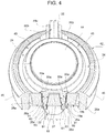
figure 2A , again, thewalls 25 and thebase plate 19 delimit acavity 37, which, in particular, has a substantially cylindrical shape. Thehub 17 further comprises alight reflection portion 38, which is housed in thecavity 37 and axially protrudes from thebase plate 19 in an opposite direction relative to theshaft 11, namely on the same side where thewalls 25 protrude. According tofigure 3 , theportion 38 joins thepointer 27 to thetail 32 and is axially delimited byreflection surfaces 39, usually called "prisms", which are positioned and shaped so as to reflect the light coming from theshaft 11 towards thefaces pointer 27 visible to the driver, in particular under night driving conditions, whereas the lighting of thetail 32 mainly has an aesthetic function. - With reference to
figures 2B ,4 and6 , the device 1 further comprises onesingle cap 42, which is distinct from thebody 10 and from thepiece 22, is mounted on thehub 17 in a fixed position and is defined by a single piece, for example obtained through plastic material moulding. - The
cap 42 prevents the light from being transmitted, but has two throughopenings 43, which are aligned with theareas 24 of thehub 17 in order to allow respective light flows to come out through thecap 42 and, hence, have the light emitted by theareas 24 be perceived on the outside, in addition to the light emitted by thepointer 27 and by thetail 32. In particular, the throughopenings 43 substantially have the same shape as theareas 24; the light emitted through the throughopenings 43 mainly fulfils an aesthetic function. - The
cap 42 preferably consists of a material capable of blocking light. According to a variant which is not shown herein, thecap 42 is made of a material covered by a coating capable of blocking light. - The
cap 42 substantially has, on the outside, the shape of an upside-down cup. In particular, thecap 42 comprises anintermediate wall 44, which is transverse to theaxis 12 and is arranged radially on the inside relative to theareas 24, and a lateral portion, which is arranged radially on the outside relative to theareas 24, surrounds thewalls 25 and, specifically, consists of twolateral walls 45 diametrically opposite one another. Thewall 44 closes thecavity 37, in a position opposite and axially facing thebase plate 19, whereas thewalls 45 end, in a circumferential direction, withrespective ends 45a defining, between one another, aslit 46a, and withrespective ends 45b diametrically opposite relative to theends 45a and defining, between one another, aslit 46b. Theslits axis 28; theslit 46a is crossed by thepointer 27, whereas theslit 46b is crossed by thetail 32. - In particular, in the area of the
slit 46a, thecap 42 comprises a pair ofappendages 47a, which protrude from theends 45a parallel to theaxis 28 towards the outside, beside thefaces 31, so as to prolong the radial extension of theslit 46a. Similarly, in the area of theslit 46b, thecap 42 comprises a pair ofappendages 47b, which protrude from theends 45b towards the outside parallel to theaxis 28, beside thefaces 35, so as to prolong the radial extension of theslit 46b. - According to an aspect of the invention, the
cap 42 comprisesconnection portions wall 44 to theends portions 50a are provided in the area of thegaps 26a, so as to cover them, and are spaced apart from one another in a circumferential direction, so as to leave an area of theface 30 uncovered and visible from the outside. Similarly, twoportions 50b are provided in the area of thegaps 26b, so as to cover them, and are spaced apart from one another in a circumferential direction, so as to leave an area of theface 34 uncovered and visible from the outside. - Therefore, the through
openings 43 are radially delimited inwards by thewall 44, are radially delimited outwards by thewalls 45 and are delimited in a circumferential direction by theportions - With reference to
figures 5 and6 , thecap 42 further comprises two shieldingwalls 53, which protrude into thecavity 37, from thewall 44 towards thebase plate 19, preferably in a direction parallel to theaxis 12, so as to be radially interposed between theportion 38 and thewalls 25, respectively. Thewalls 53 preferably have a height that is such as to allow them to rest against thebase plate 19. - In this way, the light part coming out of the
portion 38 in thecavity 37 does not reach theareas 24, thus limiting interferences and/or luminosity alterations of theareas 24. In other words, the quantity of light reaching theareas 24 is basically determined by the optical features of thebase plate 19 and of thebevel 19b, regardless of the optical features of theportion 38. - As far as the optical features of the
base plate 19 are concerned, the latter is preferably provided with recesses 54 (figures 2A and5 ), which alter the passage of light towards thewalls 25 and have positions and/or dimensions and/or shapes that are such as to cause the light emitted by theareas 24 to be uniform. - According to
figure 6 , thewalls 53 are joined to theends 45a by means of respective connection and shieldingwalls 55a and to theends 45b by means of respective connection and shieldingwalls 55b. Thewalls axis 28; in particular, they extend as prolongation of thewalls 53 and are substantially aligned with theappendages axis 28. Thewalls portions base plate 19, so as to engage thegaps pointer 27 and of thetail 32, respectively. - According to a variant which is not shown herein, the
tail 32 is absent, so that thegaps 26b and theslits 46b can also be absent. In other words, without thetail 32, thewalls 45 can also be replaced by a single lateral wall, which is continuous in a circumferential direction in the area of theends 45b, and/or thewalls 25 can be replaced by a single wall, which is continuous in a circumferential direction in the area of theends 25b, without the joiningwalls 55b and, if necessary, theportions 50b. - With reference to
figure 3 , thecap 42 comprises atooth 57, which protrudes from thewall 44 towards thebase plate 19 so as to engage aseat 58 defined by theportion 38 and by thetail 32. In a diametrically opposite position, theportion 38 has no similar seat, so that thetooth 57 interferes with theportion 38 and/or with thepointer 27 if thecap 42 is mounted on thehub 17 with a wrong orientation, rotated by 180° about theaxis 12. In other words, if thecap 42 were mounted with a wrong orientation during the assembly of the device 1, thecap 42 would remain inclined relative to theaxis 12, due to the interference, so as to point out the wrong assembly. - Advantageously, the
cap 42 is not directly fixed to thehub 17, but it is fixed to thepiece 22 so as to axially hold thehub 17 between theshield 20 and thewalls 53. In particular, with reference tofigures 4 and6 , the cap 47 comprises a plurality ofpins 60, which pass through respective throughholes 61 made in thebase plate 19 and are fixed to theshield 20. For example, thepins 60 engage theholes 20a of theshield 20 and have respective ends 63, which are arranged under theshield 20 and are staked or enlarged so as to define a stop abutment for saidshield 20. - The
pins 60 preferably protrude from thewalls 53 and/or from thewalls - With reference to
figure 2A , theholes 61 are preferably made close to thegaps base plate 19a towards thewalls 25 in a radial direction relative to theaxis 12. - Other mechanical fixing means can be provided to couple the
cap 42 to thebody 10. The mechanical fixing means do not include overmoulding techniques, which should be avoided in order to prevent the material of thecap 42 from becoming integral to the light-guide material of thebody 10, thus generating absorptions and/or interferences in the transmission and reflection of the light in thebody 10. As an alternative to or in combination with the fixing systems discussed herein, thepiece 22 can be coupled to said teeth carried by theportions 45; and/or thecap 42 can be thermally welded to thepiece 22; and/or thecap 42 can directly be fixed to thehub 17, for example through thepins 60. - As a further variant, which is not shown herein, the
shield 20 is defined by a coating applied on theface 19a and, if necessary, also on theend 18 of theshaft 11. In particular, said coating is defined by a reflecting material so as to better convey the light in thebase plate 19 and avoid the dispersion of light towards thedial 5. For example, is coating is applied by means of hot printing or through screen printing. - Owing to the above, the advantages of the device 1 are evident.
- First of all, the
portions walls cap 42 to be manufactured as one single piece, as mentioned above, since they connect thewall 44 to thewalls 45, so that the number of components of the device 1 is extremely limited. In turn, the limited number of components allows manufacturers to obtain an advantageous solution in terms of manufacturing times and costs and in terms of easiness of assembly. - At the same time, the
cap 42 lets the light flow outwards through the throughopenings 43 without filtering the light and with no need to carry out, on thecap 42, covering or coating operating phases taking place after the manufacturing phased (namely, after the moulding). - Furthermore, the
walls hub 17 from one another in an optical manner and make them independent of one another. Indeed, the different parts of thecap 42 clearly separate from one another the four components of thebody 10 which are supposed to emit light, namely thepointer 27, thetail 32 and the twowalls 25. In other words, thanks to the configuration of thehub 17 and of thecap 42, the light is emitted along flows (one towards thepointer 27 and thetail 32, the other one towards the walls 25) which are substantially independent of one another inside thebody 10. - Other advantages are then evident for a person skilled in the art based on the features described above.
- Finally, it is evident that the device 1 described with reference to the accompanying drawings can be subjected to changes and variations, which do not go beyond the scope of protection of the invention, as set forth in the appended claims.
- In particular, the position, the width and the shape of the through
openings 43 and of theareas 24 could be different from the ones disclosed above by way of example; and/or theportions faces - Finally, the device 1 could be used in applications different from the automotive one.
Claims (11)
- A pointer device (1) for an indicator instrument (2), in particular for a vehicle; the device comprising:- a light-guide body (10), that is defined by a single piece, is made with light-guide material, has a rotation axis (12) and comprises:a) an external surface (16) adapted to receive light from a light source (15);b) a hub (17) comprising a base surface (19a) and a light transmission portion (25), which axially ends with at least one light emission area (24), at the opposite axial side in respect to said base surface (19a);c) a pointer (27), which radially protrudes outwards from said hub (17);- a shield (20), that covers said base surface (19a) at least partially so as to block the light transmitted from said hub (17);- a cap (42), that is defined by a single piece separated from said light-guide body (10), is mounted on said hub (17) in a fixed position, and comprises:said cap (42) further comprising:a) an intermediate portion (44) radially arranged inwards in respect to said light transmission portion (25); andb) a lateral portion (45) that surrounds said light transmission portion (25);- at least one through opening (43) radially arranged between said intermediate portion (44) and said lateral portion (45) and aligned with said light emission area (24) for allowing the light to exit through said cap (42);- connection portions (50a,50b,55a,55b) extending radially and joining said intermediate portion (44) to said lateral portion (45);characterised in that said light transmission portion (25) comprises a pair of first end portions (25a) which are spaced apart from said pointer (27), in a circumferential direction, by respective first gaps (26a); said connection portions comprising first connection portions (55a) engaging, respectively, said first gaps (26a).
- The device according to claim 1, characterised in that said at least one through opening (43) is radially delimited inwards by said intermediate portion (44) and radially delimited outwards by said lateral portion (45); said connection portions comprising second connection portions (50a,50b) that delimit said at least one through opening (43) in a circumferential direction.
- The device according to claim 2, characterised in that said lateral portion (45) comprises a pair of second end portions (45a) defining between each other, in a circumferential direction, a first slit (46a) radially crossed by said pointer (27); said second connection portions joining said intermediate portion (44) to said second end portions (45a).
- The device according to claim 3, characterised in that said light-guide body (10) further comprises a tail (32), that protrudes from said hub (17) in an opposite radial direction to said pointer (27); said lateral portion (45) comprises a pair of third end portions (45b) defining between each other, in a circumferential direction, a second slit (46b) radially crossed by said tail (32); said second connection portions joining said intermediate portion (44) to said third end portions (45b).
- The device according to claim 1, characterised in that said light-guide body (10) further comprises a tail (32) that protrudes from said hub (17) in a radial direction opposite to said pointer (27); said light transmission portion (25) comprising a pair of fourth end portions (25b) that are separated from said tail (32), in a circumferential direction, by respective second gaps (26b); said connection portions comprising third connection portions (55b) engaging said second gaps (26b).
- The device according to any one of the preceding claims, characterised in that said hub (17) comprises:- a cavity (37) radially delimited by said light transmission portion (25);- a reflection portion (38) that engages said cavity (37) and is shaped in order to reflect light towards said pointer (27);said cap (42) comprising shielding walls (53) arranged in said cavity (37) so as to be radially interposed between said reflection portion (38) and said light transmission portion (25).
- The device according to claim 6, characterised in that said light-guide body (10) further comprises a tail (32) that protrudes from said hub (17) in an opposite radial direction to said pointer (27); said cap (42) comprising a tooth (57), which protrudes into said cavity (37) in order to engage a seat (58) defined by said reflection portion (38) and by said tail (32).
- The device according to claim 6, characterised in that said cap (42) is fixed so as to axially hold said hub (17) between said shield (20) and said shielding walls (53).
- The device according to any one of the preceding claims, characterised in that said cap (47) comprises a plurality of pins (60), which pass through respective first holes (61) made through said base surface (19a) and are fixed to said shield (20).
- The device according to claim 9, characterised in that said pins (60) engage respective second holes (20a) made through said shield (20) and have respective ends (63) which are arranged under said shield (20) and are staked or enlarged so as to define a stop abutment for said shield (20).
- The device according to claim 9 or 10, characterised in that said pins (60) protrude from said first connection portions (55a).
Applications Claiming Priority (1)
| Application Number | Priority Date | Filing Date | Title |
|---|---|---|---|
| IT102018000004284A IT201800004284A1 (en) | 2018-04-06 | 2018-04-06 | HAND DEVICE FOR AN INDICATOR INSTRUMENT, IN PARTICULAR FOR A VEHICLE |
Publications (2)
| Publication Number | Publication Date |
|---|---|
| EP3549807A1 true EP3549807A1 (en) | 2019-10-09 |
| EP3549807B1 EP3549807B1 (en) | 2020-06-17 |
Family
ID=62751428
Family Applications (1)
| Application Number | Title | Priority Date | Filing Date |
|---|---|---|---|
| EP19167655.0A Active EP3549807B1 (en) | 2018-04-06 | 2019-04-05 | Pointer device for an indicator instrument, in particular for a vehicle |
Country Status (7)
| Country | Link |
|---|---|
| US (1) | US11326912B2 (en) |
| EP (1) | EP3549807B1 (en) |
| JP (1) | JP7274333B2 (en) |
| CN (1) | CN110345979B (en) |
| BR (1) | BR102019007008A2 (en) |
| IT (1) | IT201800004284A1 (en) |
| MX (1) | MX2019003816A (en) |
Cited By (2)
| Publication number | Priority date | Publication date | Assignee | Title |
|---|---|---|---|---|
| US11285811B2 (en) * | 2018-07-18 | 2022-03-29 | Yazaki Corporation | Vehicle display device pointer |
| US11326912B2 (en) * | 2018-04-06 | 2022-05-10 | Marelli Europe S.P.A. | Pointer device for an indicator instrument, in particular for a vehicle |
Families Citing this family (1)
| Publication number | Priority date | Publication date | Assignee | Title |
|---|---|---|---|---|
| JP6652544B2 (en) * | 2017-11-27 | 2020-02-26 | 矢崎総業株式会社 | Meter device and meter unit having the same |
Citations (6)
| Publication number | Priority date | Publication date | Assignee | Title |
|---|---|---|---|---|
| EP0967465A2 (en) | 1998-06-19 | 1999-12-29 | MAGNETI MARELLI S.p.A. | Back-lit indicator device substantially free from halos of light around the pointer, in particular for vehicle dashboards |
| EP0984249A1 (en) | 1998-09-01 | 2000-03-08 | MAGNETI MARELLI S.p.A. | Back-lightable monoblock pointer unit |
| JP5561211B2 (en) * | 2011-03-11 | 2014-07-30 | 株式会社デンソー | Vehicle instrument |
| EP2876417B1 (en) * | 2013-11-21 | 2016-11-02 | Continental Automotive Systems US, Inc. | Illumination ring in pointer hub |
| WO2017001550A1 (en) * | 2015-07-01 | 2017-01-05 | Continental Automotive Gmbh | Pointer for vehicle |
| EP3187834A1 (en) | 2015-12-28 | 2017-07-05 | Magneti Marelli S.p.A. | Pointer device for an indicator instrument, in particular for a vehicle |
Family Cites Families (24)
| Publication number | Priority date | Publication date | Assignee | Title |
|---|---|---|---|---|
| US2328485A (en) * | 1939-03-09 | 1943-08-31 | Waltham Watch Co | Indicating instrument |
| US4625262A (en) * | 1983-07-08 | 1986-11-25 | Yazaki Corporation | Pointer illuminating structure in measuring instrument |
| US5458082A (en) * | 1994-03-24 | 1995-10-17 | Delco Electronics Corp. | Tip to tail illuminated pointer |
| WO1999039162A1 (en) * | 1998-01-29 | 1999-08-05 | Nippon Seiki Co., Ltd. | Light emitting indicator |
| US6182601B1 (en) * | 1998-05-01 | 2001-02-06 | Floscan Instrument Company, Inc. | Meter with microprocessor control of pointer and multi-status indicator |
| JP2885245B2 (en) * | 1998-06-12 | 1999-04-19 | 日本精機株式会社 | Light emission guide |
| US6161934A (en) * | 1999-07-16 | 2000-12-19 | Daimlerchrysler Corporation | Halo eliminating automotive indicator assembly |
| JP2001124600A (en) | 1999-10-29 | 2001-05-11 | Nippon Seiki Co Ltd | Meter pointer |
| JP2001281010A (en) * | 2000-03-30 | 2001-10-10 | Nippon Seiki Co Ltd | Luminous pointer |
| JP2002257604A (en) * | 2001-02-28 | 2002-09-11 | Nippon Seiki Co Ltd | Luminous pointer |
| US20050162843A1 (en) * | 2004-01-22 | 2005-07-28 | Siemens Vdo Automotive Corporation | Tip to tail to center pointer |
| JP4615931B2 (en) * | 2004-08-18 | 2011-01-19 | 矢崎総業株式会社 | Guidelines |
| GB2437548B (en) * | 2006-04-26 | 2010-09-15 | Visteon Global Tech Inc | Illumination of vehicle instrument |
| US7665413B2 (en) * | 2007-04-27 | 2010-02-23 | Continental Automotive Systems Us, Inc. | Illuminated hub pointer |
| JP5348509B2 (en) | 2010-11-11 | 2013-11-20 | 日本精機株式会社 | Pointer device and assembly method thereof |
| WO2012102231A1 (en) * | 2011-01-26 | 2012-08-02 | 矢崎総業株式会社 | Indicator member, indicator unit and indicator instrument |
| JP6394133B2 (en) | 2014-07-10 | 2018-09-26 | 株式会社デンソー | Vehicle display device |
| US9958474B2 (en) * | 2015-09-14 | 2018-05-01 | Denso International America, Inc. | Self-calibrating indicating device |
| WO2017147558A1 (en) * | 2016-02-26 | 2017-08-31 | Continental Automotive Systems, Inc. | Decorative ring pointer cap illumination |
| US10054470B2 (en) * | 2016-03-04 | 2018-08-21 | Denso International America, Inc. | Indicating device with pointer having counterweight |
| US9909906B2 (en) * | 2016-04-22 | 2018-03-06 | Denso International America, Inc. | Indicating device with dial plate having grooves |
| IT201800004284A1 (en) * | 2018-04-06 | 2019-10-06 | HAND DEVICE FOR AN INDICATOR INSTRUMENT, IN PARTICULAR FOR A VEHICLE | |
| US10859414B2 (en) * | 2018-04-18 | 2020-12-08 | N.S. International, Ltd. | Miniaturized illuminated pointer for instrument cluster |
| US10782162B1 (en) * | 2019-05-09 | 2020-09-22 | Denso International America, Inc. | Instrument cluster pointer |
-
2018
- 2018-04-06 IT IT102018000004284A patent/IT201800004284A1/en unknown
-
2019
- 2019-04-02 MX MX2019003816A patent/MX2019003816A/en unknown
- 2019-04-04 CN CN201910272695.1A patent/CN110345979B/en active Active
- 2019-04-04 US US16/375,324 patent/US11326912B2/en active Active
- 2019-04-05 BR BR102019007008-0A patent/BR102019007008A2/en unknown
- 2019-04-05 JP JP2019072637A patent/JP7274333B2/en active Active
- 2019-04-05 EP EP19167655.0A patent/EP3549807B1/en active Active
Patent Citations (6)
| Publication number | Priority date | Publication date | Assignee | Title |
|---|---|---|---|---|
| EP0967465A2 (en) | 1998-06-19 | 1999-12-29 | MAGNETI MARELLI S.p.A. | Back-lit indicator device substantially free from halos of light around the pointer, in particular for vehicle dashboards |
| EP0984249A1 (en) | 1998-09-01 | 2000-03-08 | MAGNETI MARELLI S.p.A. | Back-lightable monoblock pointer unit |
| JP5561211B2 (en) * | 2011-03-11 | 2014-07-30 | 株式会社デンソー | Vehicle instrument |
| EP2876417B1 (en) * | 2013-11-21 | 2016-11-02 | Continental Automotive Systems US, Inc. | Illumination ring in pointer hub |
| WO2017001550A1 (en) * | 2015-07-01 | 2017-01-05 | Continental Automotive Gmbh | Pointer for vehicle |
| EP3187834A1 (en) | 2015-12-28 | 2017-07-05 | Magneti Marelli S.p.A. | Pointer device for an indicator instrument, in particular for a vehicle |
Cited By (2)
| Publication number | Priority date | Publication date | Assignee | Title |
|---|---|---|---|---|
| US11326912B2 (en) * | 2018-04-06 | 2022-05-10 | Marelli Europe S.P.A. | Pointer device for an indicator instrument, in particular for a vehicle |
| US11285811B2 (en) * | 2018-07-18 | 2022-03-29 | Yazaki Corporation | Vehicle display device pointer |
Also Published As
| Publication number | Publication date |
|---|---|
| IT201800004284A1 (en) | 2019-10-06 |
| US20190310114A1 (en) | 2019-10-10 |
| JP2019191166A (en) | 2019-10-31 |
| EP3549807B1 (en) | 2020-06-17 |
| JP7274333B2 (en) | 2023-05-16 |
| BR102019007008A2 (en) | 2019-10-08 |
| MX2019003816A (en) | 2019-11-28 |
| US11326912B2 (en) | 2022-05-10 |
| CN110345979A (en) | 2019-10-18 |
| CN110345979B (en) | 2022-12-02 |
Similar Documents
| Publication | Publication Date | Title |
|---|---|---|
| EP3549807B1 (en) | Pointer device for an indicator instrument, in particular for a vehicle | |
| JP5779340B2 (en) | Vehicle lighting | |
| EP1276123B1 (en) | Rotary switch mechanism for operation panel | |
| EP1471336B1 (en) | Illuminated pointer with cover cap including translucent layer | |
| JP6209408B2 (en) | Decorative ring and method of manufacturing the decorative ring | |
| CN104567970A (en) | Needle type gauge | |
| US10584985B2 (en) | Pointer device for an indicator instrument, in particular for a vehicle | |
| US7373898B1 (en) | Pointer with one-piece hub device | |
| WO2021033381A1 (en) | Vehicular lighting device | |
| KR101526552B1 (en) | Cluster for automobile | |
| KR101722171B1 (en) | Pointer for vehicle | |
| WO2015079609A1 (en) | Meter | |
| JP2011187197A (en) | Operation panel having switch mechanism | |
| JP2009264870A (en) | Instrument apparatus | |
| KR980010966A (en) | Instruction lighting device | |
| JP2016017911A (en) | Vehicle display device | |
| JP7293922B2 (en) | Vehicle fog lamp fixing structure | |
| US20170241815A1 (en) | Indicating device with light-directing configuration | |
| JP2012118006A (en) | Illumination structure for indicator | |
| KR200365297Y1 (en) | Front panel for having indicating structure of car | |
| JP2004144618A (en) | Measuring instrument with light-emitting pointer | |
| JP2017150905A (en) | Display device and method for manufacturing display device | |
| JP2004325243A (en) | Meter illumination structure | |
| JP2017207306A (en) | Pointer instrument | |
| JP2004286481A (en) | Meter pointer lighting structure |
Legal Events
| Date | Code | Title | Description |
|---|---|---|---|
| PUAI | Public reference made under article 153(3) epc to a published international application that has entered the european phase |
Free format text: ORIGINAL CODE: 0009012 |
|
| STAA | Information on the status of an ep patent application or granted ep patent |
Free format text: STATUS: THE APPLICATION HAS BEEN PUBLISHED |
|
| AK | Designated contracting states |
Kind code of ref document: A1 Designated state(s): AL AT BE BG CH CY CZ DE DK EE ES FI FR GB GR HR HU IE IS IT LI LT LU LV MC MK MT NL NO PL PT RO RS SE SI SK SM TR |
|
| AX | Request for extension of the european patent |
Extension state: BA ME |
|
| STAA | Information on the status of an ep patent application or granted ep patent |
Free format text: STATUS: REQUEST FOR EXAMINATION WAS MADE |
|
| 17P | Request for examination filed |
Effective date: 20191114 |
|
| RIC1 | Information provided on ipc code assigned before grant |
Ipc: B60K 37/02 20060101ALI20191128BHEP Ipc: G01D 13/26 20060101ALI20191128BHEP Ipc: B60K 35/00 20060101AFI20191128BHEP |
|
| GRAP | Despatch of communication of intention to grant a patent |
Free format text: ORIGINAL CODE: EPIDOSNIGR1 |
|
| STAA | Information on the status of an ep patent application or granted ep patent |
Free format text: STATUS: GRANT OF PATENT IS INTENDED |
|
| INTG | Intention to grant announced |
Effective date: 20200107 |
|
| RAP1 | Party data changed (applicant data changed or rights of an application transferred) |
Owner name: MARELLI EUROPE S.P.A. |
|
| GRAS | Grant fee paid |
Free format text: ORIGINAL CODE: EPIDOSNIGR3 |
|
| GRAA | (expected) grant |
Free format text: ORIGINAL CODE: 0009210 |
|
| STAA | Information on the status of an ep patent application or granted ep patent |
Free format text: STATUS: THE PATENT HAS BEEN GRANTED |
|
| AK | Designated contracting states |
Kind code of ref document: B1 Designated state(s): AL AT BE BG CH CY CZ DE DK EE ES FI FR GB GR HR HU IE IS IT LI LT LU LV MC MK MT NL NO PL PT RO RS SE SI SK SM TR |
|
| REG | Reference to a national code |
Ref country code: GB Ref legal event code: FG4D |
|
| REG | Reference to a national code |
Ref country code: CH Ref legal event code: EP |
|
| REG | Reference to a national code |
Ref country code: IE Ref legal event code: FG4D |
|
| REG | Reference to a national code |
Ref country code: DE Ref legal event code: R096 Ref document number: 602019000188 Country of ref document: DE |
|
| REG | Reference to a national code |
Ref country code: AT Ref legal event code: REF Ref document number: 1280893 Country of ref document: AT Kind code of ref document: T Effective date: 20200715 |
|
| PG25 | Lapsed in a contracting state [announced via postgrant information from national office to epo] |
Ref country code: NO Free format text: LAPSE BECAUSE OF FAILURE TO SUBMIT A TRANSLATION OF THE DESCRIPTION OR TO PAY THE FEE WITHIN THE PRESCRIBED TIME-LIMIT Effective date: 20200917 Ref country code: GR Free format text: LAPSE BECAUSE OF FAILURE TO SUBMIT A TRANSLATION OF THE DESCRIPTION OR TO PAY THE FEE WITHIN THE PRESCRIBED TIME-LIMIT Effective date: 20200918 Ref country code: LT Free format text: LAPSE BECAUSE OF FAILURE TO SUBMIT A TRANSLATION OF THE DESCRIPTION OR TO PAY THE FEE WITHIN THE PRESCRIBED TIME-LIMIT Effective date: 20200617 Ref country code: SE Free format text: LAPSE BECAUSE OF FAILURE TO SUBMIT A TRANSLATION OF THE DESCRIPTION OR TO PAY THE FEE WITHIN THE PRESCRIBED TIME-LIMIT Effective date: 20200617 Ref country code: FI Free format text: LAPSE BECAUSE OF FAILURE TO SUBMIT A TRANSLATION OF THE DESCRIPTION OR TO PAY THE FEE WITHIN THE PRESCRIBED TIME-LIMIT Effective date: 20200617 |
|
| REG | Reference to a national code |
Ref country code: LT Ref legal event code: MG4D |
|
| REG | Reference to a national code |
Ref country code: NL Ref legal event code: MP Effective date: 20200617 |
|
| PG25 | Lapsed in a contracting state [announced via postgrant information from national office to epo] |
Ref country code: RS Free format text: LAPSE BECAUSE OF FAILURE TO SUBMIT A TRANSLATION OF THE DESCRIPTION OR TO PAY THE FEE WITHIN THE PRESCRIBED TIME-LIMIT Effective date: 20200617 Ref country code: HR Free format text: LAPSE BECAUSE OF FAILURE TO SUBMIT A TRANSLATION OF THE DESCRIPTION OR TO PAY THE FEE WITHIN THE PRESCRIBED TIME-LIMIT Effective date: 20200617 Ref country code: LV Free format text: LAPSE BECAUSE OF FAILURE TO SUBMIT A TRANSLATION OF THE DESCRIPTION OR TO PAY THE FEE WITHIN THE PRESCRIBED TIME-LIMIT Effective date: 20200617 Ref country code: BG Free format text: LAPSE BECAUSE OF FAILURE TO SUBMIT A TRANSLATION OF THE DESCRIPTION OR TO PAY THE FEE WITHIN THE PRESCRIBED TIME-LIMIT Effective date: 20200917 |
|
| REG | Reference to a national code |
Ref country code: AT Ref legal event code: MK05 Ref document number: 1280893 Country of ref document: AT Kind code of ref document: T Effective date: 20200617 |
|
| PG25 | Lapsed in a contracting state [announced via postgrant information from national office to epo] |
Ref country code: AL Free format text: LAPSE BECAUSE OF FAILURE TO SUBMIT A TRANSLATION OF THE DESCRIPTION OR TO PAY THE FEE WITHIN THE PRESCRIBED TIME-LIMIT Effective date: 20200617 Ref country code: NL Free format text: LAPSE BECAUSE OF FAILURE TO SUBMIT A TRANSLATION OF THE DESCRIPTION OR TO PAY THE FEE WITHIN THE PRESCRIBED TIME-LIMIT Effective date: 20200617 |
|
| PG25 | Lapsed in a contracting state [announced via postgrant information from national office to epo] |
Ref country code: PT Free format text: LAPSE BECAUSE OF FAILURE TO SUBMIT A TRANSLATION OF THE DESCRIPTION OR TO PAY THE FEE WITHIN THE PRESCRIBED TIME-LIMIT Effective date: 20201019 Ref country code: CZ Free format text: LAPSE BECAUSE OF FAILURE TO SUBMIT A TRANSLATION OF THE DESCRIPTION OR TO PAY THE FEE WITHIN THE PRESCRIBED TIME-LIMIT Effective date: 20200617 Ref country code: RO Free format text: LAPSE BECAUSE OF FAILURE TO SUBMIT A TRANSLATION OF THE DESCRIPTION OR TO PAY THE FEE WITHIN THE PRESCRIBED TIME-LIMIT Effective date: 20200617 Ref country code: ES Free format text: LAPSE BECAUSE OF FAILURE TO SUBMIT A TRANSLATION OF THE DESCRIPTION OR TO PAY THE FEE WITHIN THE PRESCRIBED TIME-LIMIT Effective date: 20200617 Ref country code: SM Free format text: LAPSE BECAUSE OF FAILURE TO SUBMIT A TRANSLATION OF THE DESCRIPTION OR TO PAY THE FEE WITHIN THE PRESCRIBED TIME-LIMIT Effective date: 20200617 Ref country code: EE Free format text: LAPSE BECAUSE OF FAILURE TO SUBMIT A TRANSLATION OF THE DESCRIPTION OR TO PAY THE FEE WITHIN THE PRESCRIBED TIME-LIMIT Effective date: 20200617 Ref country code: AT Free format text: LAPSE BECAUSE OF FAILURE TO SUBMIT A TRANSLATION OF THE DESCRIPTION OR TO PAY THE FEE WITHIN THE PRESCRIBED TIME-LIMIT Effective date: 20200617 |
|
| PG25 | Lapsed in a contracting state [announced via postgrant information from national office to epo] |
Ref country code: PL Free format text: LAPSE BECAUSE OF FAILURE TO SUBMIT A TRANSLATION OF THE DESCRIPTION OR TO PAY THE FEE WITHIN THE PRESCRIBED TIME-LIMIT Effective date: 20200617 Ref country code: SK Free format text: LAPSE BECAUSE OF FAILURE TO SUBMIT A TRANSLATION OF THE DESCRIPTION OR TO PAY THE FEE WITHIN THE PRESCRIBED TIME-LIMIT Effective date: 20200617 Ref country code: IS Free format text: LAPSE BECAUSE OF FAILURE TO SUBMIT A TRANSLATION OF THE DESCRIPTION OR TO PAY THE FEE WITHIN THE PRESCRIBED TIME-LIMIT Effective date: 20201017 |
|
| REG | Reference to a national code |
Ref country code: DE Ref legal event code: R097 Ref document number: 602019000188 Country of ref document: DE |
|
| PLBE | No opposition filed within time limit |
Free format text: ORIGINAL CODE: 0009261 |
|
| STAA | Information on the status of an ep patent application or granted ep patent |
Free format text: STATUS: NO OPPOSITION FILED WITHIN TIME LIMIT |
|
| PG25 | Lapsed in a contracting state [announced via postgrant information from national office to epo] |
Ref country code: DK Free format text: LAPSE BECAUSE OF FAILURE TO SUBMIT A TRANSLATION OF THE DESCRIPTION OR TO PAY THE FEE WITHIN THE PRESCRIBED TIME-LIMIT Effective date: 20200617 |
|
| 26N | No opposition filed |
Effective date: 20210318 |
|
| PG25 | Lapsed in a contracting state [announced via postgrant information from national office to epo] |
Ref country code: MC Free format text: LAPSE BECAUSE OF FAILURE TO SUBMIT A TRANSLATION OF THE DESCRIPTION OR TO PAY THE FEE WITHIN THE PRESCRIBED TIME-LIMIT Effective date: 20200617 |
|
| PG25 | Lapsed in a contracting state [announced via postgrant information from national office to epo] |
Ref country code: LU Free format text: LAPSE BECAUSE OF NON-PAYMENT OF DUE FEES Effective date: 20210405 |
|
| REG | Reference to a national code |
Ref country code: BE Ref legal event code: MM Effective date: 20210430 |
|
| PG25 | Lapsed in a contracting state [announced via postgrant information from national office to epo] |
Ref country code: IE Free format text: LAPSE BECAUSE OF NON-PAYMENT OF DUE FEES Effective date: 20210405 |
|
| PG25 | Lapsed in a contracting state [announced via postgrant information from national office to epo] |
Ref country code: IS Free format text: LAPSE BECAUSE OF FAILURE TO SUBMIT A TRANSLATION OF THE DESCRIPTION OR TO PAY THE FEE WITHIN THE PRESCRIBED TIME-LIMIT Effective date: 20201017 |
|
| PG25 | Lapsed in a contracting state [announced via postgrant information from national office to epo] |
Ref country code: BE Free format text: LAPSE BECAUSE OF NON-PAYMENT OF DUE FEES Effective date: 20210430 |
|
| REG | Reference to a national code |
Ref country code: CH Ref legal event code: PL |
|
| PG25 | Lapsed in a contracting state [announced via postgrant information from national office to epo] |
Ref country code: LI Free format text: LAPSE BECAUSE OF NON-PAYMENT OF DUE FEES Effective date: 20220430 Ref country code: CH Free format text: LAPSE BECAUSE OF NON-PAYMENT OF DUE FEES Effective date: 20220430 |
|
| PGFP | Annual fee paid to national office [announced via postgrant information from national office to epo] |
Ref country code: FR Payment date: 20230321 Year of fee payment: 5 |
|
| PGFP | Annual fee paid to national office [announced via postgrant information from national office to epo] |
Ref country code: TR Payment date: 20230323 Year of fee payment: 5 Ref country code: IT Payment date: 20230322 Year of fee payment: 5 |
|
| PG25 | Lapsed in a contracting state [announced via postgrant information from national office to epo] |
Ref country code: CY Free format text: LAPSE BECAUSE OF FAILURE TO SUBMIT A TRANSLATION OF THE DESCRIPTION OR TO PAY THE FEE WITHIN THE PRESCRIBED TIME-LIMIT Effective date: 20200617 |
|
| PG25 | Lapsed in a contracting state [announced via postgrant information from national office to epo] |
Ref country code: HU Free format text: LAPSE BECAUSE OF FAILURE TO SUBMIT A TRANSLATION OF THE DESCRIPTION OR TO PAY THE FEE WITHIN THE PRESCRIBED TIME-LIMIT; INVALID AB INITIO Effective date: 20190405 |
|
| PGFP | Annual fee paid to national office [announced via postgrant information from national office to epo] |
Ref country code: DE Payment date: 20230321 Year of fee payment: 5 |
|
| PG25 | Lapsed in a contracting state [announced via postgrant information from national office to epo] |
Ref country code: SI Free format text: LAPSE BECAUSE OF FAILURE TO SUBMIT A TRANSLATION OF THE DESCRIPTION OR TO PAY THE FEE WITHIN THE PRESCRIBED TIME-LIMIT Effective date: 20200617 |
|
| GBPC | Gb: european patent ceased through non-payment of renewal fee |
Effective date: 20230405 |
|
| PG25 | Lapsed in a contracting state [announced via postgrant information from national office to epo] |
Ref country code: GB Free format text: LAPSE BECAUSE OF NON-PAYMENT OF DUE FEES Effective date: 20230405 |
|
| PG25 | Lapsed in a contracting state [announced via postgrant information from national office to epo] |
Ref country code: GB Free format text: LAPSE BECAUSE OF NON-PAYMENT OF DUE FEES Effective date: 20230405 |
|
| PG25 | Lapsed in a contracting state [announced via postgrant information from national office to epo] |
Ref country code: MK Free format text: LAPSE BECAUSE OF FAILURE TO SUBMIT A TRANSLATION OF THE DESCRIPTION OR TO PAY THE FEE WITHIN THE PRESCRIBED TIME-LIMIT Effective date: 20200617 |