EP3549801A1 - Vehicular air conditioning device - Google Patents
Vehicular air conditioning device Download PDFInfo
- Publication number
- EP3549801A1 EP3549801A1 EP17875439.6A EP17875439A EP3549801A1 EP 3549801 A1 EP3549801 A1 EP 3549801A1 EP 17875439 A EP17875439 A EP 17875439A EP 3549801 A1 EP3549801 A1 EP 3549801A1
- Authority
- EP
- European Patent Office
- Prior art keywords
- particulate
- concentration
- particulate concentration
- vehicle
- air conditioner
- Prior art date
- Legal status (The legal status is an assumption and is not a legal conclusion. Google has not performed a legal analysis and makes no representation as to the accuracy of the status listed.)
- Granted
Links
Images




Classifications
-
- B—PERFORMING OPERATIONS; TRANSPORTING
- B60—VEHICLES IN GENERAL
- B60H—ARRANGEMENTS OF HEATING, COOLING, VENTILATING OR OTHER AIR-TREATING DEVICES SPECIALLY ADAPTED FOR PASSENGER OR GOODS SPACES OF VEHICLES
- B60H1/00—Heating, cooling or ventilating devices
- B60H1/00642—Control systems or circuits; Control members or indication devices for heating, cooling or ventilating devices
- B60H1/00735—Control systems or circuits characterised by their input, i.e. by the detection, measurement or calculation of particular conditions, e.g. signal treatment, dynamic models
- B60H1/008—Control systems or circuits characterised by their input, i.e. by the detection, measurement or calculation of particular conditions, e.g. signal treatment, dynamic models the input being air quality
-
- B—PERFORMING OPERATIONS; TRANSPORTING
- B60—VEHICLES IN GENERAL
- B60H—ARRANGEMENTS OF HEATING, COOLING, VENTILATING OR OTHER AIR-TREATING DEVICES SPECIALLY ADAPTED FOR PASSENGER OR GOODS SPACES OF VEHICLES
- B60H1/00—Heating, cooling or ventilating devices
-
- B—PERFORMING OPERATIONS; TRANSPORTING
- B60—VEHICLES IN GENERAL
- B60H—ARRANGEMENTS OF HEATING, COOLING, VENTILATING OR OTHER AIR-TREATING DEVICES SPECIALLY ADAPTED FOR PASSENGER OR GOODS SPACES OF VEHICLES
- B60H1/00—Heating, cooling or ventilating devices
- B60H1/00642—Control systems or circuits; Control members or indication devices for heating, cooling or ventilating devices
- B60H1/0073—Control systems or circuits characterised by particular algorithms or computational models, e.g. fuzzy logic or dynamic models
-
- B—PERFORMING OPERATIONS; TRANSPORTING
- B60—VEHICLES IN GENERAL
- B60H—ARRANGEMENTS OF HEATING, COOLING, VENTILATING OR OTHER AIR-TREATING DEVICES SPECIALLY ADAPTED FOR PASSENGER OR GOODS SPACES OF VEHICLES
- B60H1/00—Heating, cooling or ventilating devices
- B60H1/00642—Control systems or circuits; Control members or indication devices for heating, cooling or ventilating devices
- B60H1/00735—Control systems or circuits characterised by their input, i.e. by the detection, measurement or calculation of particular conditions, e.g. signal treatment, dynamic models
- B60H1/00742—Control systems or circuits characterised by their input, i.e. by the detection, measurement or calculation of particular conditions, e.g. signal treatment, dynamic models by detection of the vehicle occupants' presence; by detection of conditions relating to the body of occupants, e.g. using radiant heat detectors
-
- B—PERFORMING OPERATIONS; TRANSPORTING
- B60—VEHICLES IN GENERAL
- B60H—ARRANGEMENTS OF HEATING, COOLING, VENTILATING OR OTHER AIR-TREATING DEVICES SPECIALLY ADAPTED FOR PASSENGER OR GOODS SPACES OF VEHICLES
- B60H1/00—Heating, cooling or ventilating devices
- B60H1/24—Ventilating devices where the heating or cooling is irrelevant
-
- B—PERFORMING OPERATIONS; TRANSPORTING
- B60—VEHICLES IN GENERAL
- B60H—ARRANGEMENTS OF HEATING, COOLING, VENTILATING OR OTHER AIR-TREATING DEVICES SPECIALLY ADAPTED FOR PASSENGER OR GOODS SPACES OF VEHICLES
- B60H3/00—Other air-treating devices
-
- B—PERFORMING OPERATIONS; TRANSPORTING
- B60—VEHICLES IN GENERAL
- B60H—ARRANGEMENTS OF HEATING, COOLING, VENTILATING OR OTHER AIR-TREATING DEVICES SPECIALLY ADAPTED FOR PASSENGER OR GOODS SPACES OF VEHICLES
- B60H3/00—Other air-treating devices
- B60H3/06—Filtering
-
- G—PHYSICS
- G01—MEASURING; TESTING
- G01N—INVESTIGATING OR ANALYSING MATERIALS BY DETERMINING THEIR CHEMICAL OR PHYSICAL PROPERTIES
- G01N15/00—Investigating characteristics of particles; Investigating permeability, pore-volume or surface-area of porous materials
- G01N15/06—Investigating concentration of particle suspensions
Definitions
- the present disclosure relates to a vehicular air conditioner.
- the particulate detector described in Patent Literature 1 detects a particulate amount based on an output of a light receiving element and identifies the particulate as dust when a difference between a maximum value and an average value of the output of the light receiving element in a certain period is larger than a predetermined value.
- the particulate detector obtains a moving average of the number of times of dust identification per unit time over several unit times, and calculates a dust concentration based on the average number of times of dust identification.
- Patent Literature 1 JP 2003-065940 A
- the calculation results of the particulate concentration displayed on the display may fall out of synchronization with the actual particulate concentration, which may bring a feeling of strangeness to the user.
- the present disclosure has been made with the above-described circumstances in view and its object is to provide a vehicular air conditioner capable of detecting a particulate concentration that is closer to an actual particulate concentration in a situation.
- a vehicular air conditioner of the present disclosure air-conditions a vehicle interior by blowing air through an air conditioning duct into the vehicle interior.
- the vehicular air conditioner includes a particulate sensor and a calculation section.
- the particulate sensor detects a particulate concentration in the air flowing through the air conditioning duct.
- the calculation section calculates an average value of the particulate concentration by averaging the particulate concentrations detected by the particulate sensor over a moving-average time period. When a current particulate concentration detected by the particulate sensor is higher than a predetermined threshold concentration, the calculation section makes the moving-average time period shorter than the moving-average time period used when the current particulate concentration is equal to or lower than the threshold concentration.
- the moving-average time period used to calculate the average value of the particulate concentration becomes short. In this way, the current particulate concentration becomes likely to be reflected in the average value of the particulate concentration and therefore it is possible to detect the particulate concentration that is closer to an actual particulate concentration in the situation.
- a vehicular air conditioner 1 in the present embodiment includes an air conditioning duct 10 and an air conditioning unit 20.
- the vehicular air conditioner 1 is provided inside an instrument panel of a vehicle.
- an air passage 11 that introduces conditioned air for air-conditioning a vehicle interior into the vehicle interior is formed.
- the air flows in a direction shown by an arrow A in FIG. 1 .
- an outside air suction port 12 and an inside air suction port 13 are formed as portions that take air into the air passage 11 from outside the air conditioning duct 10.
- the outside air suction port 12 is a portion for taking outside air which is air outside the vehicle interior into the air passage 11.
- the inside air suction port 13 is a portion for taking inside air which is air in the vehicle interior into the air passage 11.
- a filter 17 is disposed at a portion in the air conditioning duct 10 on a downstream side of the outside air suction port 12 and the inside air suction port 13.
- the filter 17 removes particulates such as dust included in the outside air taken in from the outside air suction port 12 or the inside air taken in from the inside air suction port 13.
- a defroster blow outlet 14 blows out the air flowing through the air conditioning duct 10 toward an inner face of a windshield of the vehicle.
- the face blow outlet 15 blows out the air flowing through the air conditioning duct 10 toward a driver or an occupant in a passenger's seat.
- the foot blow outlet 16 blows out the air flowing through the air conditioning duct 10 toward feet of the driver or the occupant in the passenger's seat.
- the air conditioning unit 20 produces the conditioned air from the air introduced into the air passage 11 from the outside air suction port 12 or the inside air suction port 13.
- the conditioned air is air for air-conditioning the vehicle interior.
- the air conditioning unit 20 includes a blower fan 21, an evaporator 22, and a heater core 23.
- the blower fan 21 is disposed on a downstream side of the outside air suction port 12 and the inside air suction port 13 in the air flow direction A.
- the blower fan 21 rotates in accordance with a supply of electric power to thereby generate an airflow in the air passage 11.
- a volume of the air flowing through the air passage 11 i.e., a volume of the conditioned air is adjusted.
- the evaporator 22 is disposed on a downstream side of the blower fan 21 in the air flow direction A.
- the evaporator 22 is a component element of a refrigeration cycle (not shown).
- the refrigeration cycle is formed by a compressor, a condenser, and an expansion valve in addition to the evaporator 22.
- refrigerant circulates through the compressor, the condenser, the expansion valve, and the evaporator 22 in this order.
- the refrigerant flowing inside exchanges heat with the air in the air passage 11 to thereby evaporate and vaporize.
- the evaporator 22 has a function of cooling the air flowing through the air passage 11 by utilizing heat of vaporization in vaporization of the refrigerant and a function of dehumidifying the air flowing through the air passage 11.
- the heater core 23 is disposed on a downstream side of the evaporator 22 in the air flow direction A.
- the heater core 23 is connected to an engine (not shown) by a pipe.
- Engine cooling water circulates between the engine and the heater core 23 through the pipe.
- the heater core 23 heats the air flowing through the air passage 11 by utilizing the engine cooling water flowing inside the heater core 23 as a heat source.
- the air conditioning unit 20 further includes an inside-outside air switching door 24, an air mix door 25, and blow outlet switching doors 26, 27, and 28.
- the inside-outside air switching door 24 opens and closes the outside air suction port 12 and the inside air suction port 13.
- the inside-outside air switching door 24 is in an inside air introducing position shown by solid lines in the figure, the outside air suction port 12 is closed and the inside air suction port 13 is open.
- the vehicular air conditioner 1 is in an inside air circulating mode in which the inside air is taken into the air passage 11 from the inside air suction port 13.
- the inside-outside air switching door 24 is in an outside air introducing position shown by broken lines in the figure, the inside air suction port 13 is closed and the outside air suction port 12 is open.
- the vehicular air conditioner 1 is in an outside air introducing mode in which the outside air is taken into the air passage 11 from the outside air suction port 12.
- the air mix door 25 adjusts a ratio between a volume of the air flowing into the heater core 23 and a volume of the air bypassing the heater core 23. To put it concretely, a position of the air mix door 25 can be adjusted between a maximum heating position shown by solid lines in the figure and a maximum cooling position shown by broken lines in the figure. When the air mix door 25 is in the maximum heating position, most of the air passing through the evaporator 22 passes through the heater core 23 and therefore a temperature of the conditioned air increases the most. When the air mix door 25 is in the maximum cooling position, most of the air passing through the evaporator 22 bypasses the heater core 23.
- the air cooled in the evaporator 22 flows to the respective blow outlets 14 to 16 as it is and therefore the temperature of the conditioned air decreases the most.
- the temperature of the conditioned air is adjusted.
- the blow outlet switching doors 26 to 28 switch between open and closed states of the defroster blow outlet 14, the face blow outlet 15, and the foot blow outlet 16, respectively. When at least one of the blow outlet switching doors 26 to 28 is brought into the open state, the conditioned air is blown out from the open blow outlet toward the vehicle interior.
- the vehicular air conditioner 1 includes a controller 60, a display 61, a particulate sensor 70, and an ECU (electronic control unit) 80.
- the ECU 80 corresponds to a calculation section.
- the controller 60 is a unit operated by the driver to adjust a volume, a temperature, and the like of the conditioned air.
- the controller 60 is disposed on the instrument panel of the vehicle, for example. With the controller 60, it is possible to select one of the outside air introducing mode and the inside air circulating mode, for example. With the controller 60, it is also possible to set the volume of the conditioned air, the temperature of the conditioned air, the blow outlet of the conditioned air, and the like.
- the controller 60 outputs the pieces of control information to the ECU 80.
- the display 61 is a unit that displays various kinds of information of the vehicular air conditioner 1.
- a display of a car navigation system of the vehicle is used as a substitute for the display 61 of the vehicular air conditioner 1. It is also possible to use a dedicated display 61 for the vehicular air conditioner 1.
- the particulate sensor 70 is provided to a bypass path 18 formed at the portion of the air conditioning duct 10 where the filter 17 is formed.
- the bypass path 18 is a portion for causing the outside air taken in from the outside air suction port 12 or the inside air taken in from the inside air suction port 13 to flow while bypassing the filter 17.
- the particulate sensor 70 detects a concentration Cd of the particulates included in the air flowing through the bypass path 18.
- the particulate sensor 70 includes a light emitting element that applies light to the bypass path 18 and a light receiving element that receives the light applied by the light emitting element, for example.
- the light receiving element outputs a voltage signal corresponding to the received light.
- the particulate sensor 70 outputs a voltage signal corresponding to the output voltage of the light receiving element as a detection signal Vd.
- An amount of light received by the light receiving element changes according to the particulate concentration Cd of the air passing through the bypass path 18.
- the detection signal Vd of the particulate sensor 70 changes according to the particulate concentration Cd of the air flowing through the air conditioning duct 10.
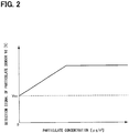
- the detection signal Vd of the particulate sensor 70 indicates a criterion voltage Voc when the particulate concentration is 0 [ ⁇ g/m 3 ] as shown in FIG. 2 .
- the detection signal Vd of the particulate sensor 70 increases as the particulate concentration Cd increases and becomes a constant value when the particulate concentration Cd becomes equal to or higher than a predetermined concentration.
- Detection signals of various sensors for detecting a condition of the vehicle and switches are taken into the ECU 80.
- an output signal of a starter switch 71 is taken into the ECU 80.
- the starter switch 71 is a switch operated by the driver to start the vehicle.
- an ignition switch operated to start the engine of the vehicle and a push-button switch operated to start a hybrid car or an electric car, or the like can be used.
- the starter switch 71 When the driver turns on or off the starter switch 71, the starter switch 71 outputs a signal corresponding to the operation.
- the ECU 80 is mainly formed by a microcomputer including a CPU 81, a memory 82, and the like.
- the ECU 80 acquires control information from the controller 60 and drives the air conditioning unit 20 based on the acquired control information. In this way, the conditioned air corresponding to the control information of the controller 60 is produced by the air conditioning unit 20.
- the ECU 80 takes in the detection signal Vd of the particulate sensor 70.
- the ECU 80 acquires pieces of information about the particulate concentration Cd based on the detection signals Vd of the particulate sensor 70 and calculates an average value ACd of the particulate concentration by averaging the acquired particulate concentrations Cd over a moving-average time period.
- the ECU 80 displays the calculated average value ACd of the particulate concentration on the display 61.
- the ECU 80 performs the processing steps shown in FIG. 3 when the starter switch 71 is turned on.
- the ECU 80 first performs initial setting of the particulate sensor 70 as the processing in step S10. To put it concretely, the ECU 80 acquires the detection signal Vd of the particulate sensor 70 immediately after the starter switch 71 is turned on and stores the acquired detection signal Vd as an initial value Vdb of the detection signal Vd of the particulate sensor 70. The reason for this is as follows.
- the initial value Vdb of the detection signal Vd of the particulate sensor 70 may change with time due to accumulation of the particulates on the light emitting element and the light receiving element.
- the initial value Vdb is a value of the detection signal Vd output from the particulate sensor 70 when air not including particulates is detected. Therefore, it is necessary to calculate the particulate concentration Cd in consideration of change of the initial value Vdb of the detection signal Vd of the particulate sensor 70 with time.
- the ECU 80 in the present embodiment acquires the detection signal Vd output from the particulate sensor 70 immediately after the starter switch 71 is turned on. Air is not flowing through the bypass path 18 immediately after the starter switch 71 is turned on. Therefore, by acquiring the detection signal Vd of the particulate sensor 70 at this time, it is possible to acquire the detection signal Vd output from the particulate sensor 70 when the air not including the particulates is detected.
- the ECU 80 stores the acquired detection signal Vd in the memory 82 as the initial value Vdb.
- the ECU 80 acquires the detection signal Vd of the particulate sensor 70 as the processing in step S11 following the processing in step S10 and calculates a current particulate concentration Cd(1) as the processing in step S12. To put it concretely, the ECU 80 calculates the current particulate concentration Cd(1) based on a difference value between the detection signal Vd of the particulate sensor 70 acquired in the processing in step S11 and the initial value Vdb stored in the memory 82.
- the ECU 80 determines whether the current particulate concentration Cd(1) is higher than a predetermined threshold concentration Cd1 as the processing in step S13.
- the threshold concentration Cd1 is obtained in advance by an experiment or the like and stored in the memory 82 for determination of whether a large number of particulates are included in the air.
- a value defined by an air quality index may be used as the threshold concentration Cd1.
- the ECU 80 sets the moving-average time period Tma to a criterion time Tmab as the processing in step S16.
- the criterion time Tmab is set in advance and stored in the memory 82.
- the ECU 80 calculates a correction time ⁇ Tma1 based on the current particulate concentration Cd(1) as the processing in step S14.
- the correction time ⁇ Tma1 is a value for correcting the moving-average time period Tma used to calculate the average value ACd of the particulate concentration.
- a fixed value set in advance can be used, for example.
- a variable value that varies according to the current particulate concentration Cd(1) can be used as well. To put it concretely, the higher the current particulate concentration Cd(1) is, the larger value the ECU 80 may set as the correction time ⁇ Tma1.
- the ECU 80 shortens the moving-average time period Tma as the processing in step S15 following step S14. To put it concretely, the ECU 80 subtracts the correction time ⁇ Tma1 from the criterion time Tmab and sets a subtracted value, "Tmab - ⁇ Tma" as the moving-average time period Tma.
- the ECU 80 calculates the average value ACd of the particulate concentration as the processing in step S17. To put it concretely, the ECU 80 calculates the average value ACd of the particulate concentration by calculating the sum of the plurality of particulate concentrations Cd(1) to Cd(n) detected by the particulate sensor 70 for a period of the moving-average time period Tma before the present and dividing the sum by the number n of data.
- n is an integer equal to or greater than 2.
- the moving-average time period Tma is shortened to "Tmab - ⁇ Tma" in step S15
- the number n of data of the particulate concentration Cd used to calculate the average value ACd of the particulate concentration is smaller than when the moving-average time period Tma is set to the criterion time Tmab in step S16.
- the current particulate concentration Cd(1) becomes likely to be reflected in the average value ACd of the particulate concentration.
- the ECU 80 displays the calculated average value ACd of the particulate concentration on the display 61 as the processing in step S18 following the processing in step S17 and then returns to the processing in step S11. Then, the ECU 80 repeatedly performs the processing steps in steps S11 to S17 at predetermined intervals.
- the moving-average time period Tma used to calculate the average value ACd of the particulate concentration becomes short.
- the current particulate concentration Cd(1) becomes likely to be reflected in the average value ACd of the particulate concentration and therefore it is possible to detect the particulate concentration that is closer to the actual particulate concentration in the situation.
- the vehicular air conditioner 1 in the present embodiment further includes a window opening-closing sensor 72 that detects an open-closed state of a window of a vehicle.
- the window opening-closing sensor 72 detects the open-closed state of the window of the vehicle and outputs a detection signal corresponding to the detected open-closed state of the window.
- the output signal of the window opening-closing sensor 72 is taken into an ECU 80.
- the ECU 80 acquires information about the open-closed state of the window of the vehicle based on the output signal of the window opening-closing sensor 72.
- the ECU 80 determines whether the window of the vehicle is open as processing in step S20.
- the processing in step S20 corresponds to processing for determining whether an operation that causes an increase in a particulate concentration in a vehicle interior is performed.
- the ECU 80 maintains a moving-average time period Tma calculated in the processing in step S15 or the processing in step S16 as it is as processing in step S22.
- step S20 determines that the particulate concentration in the vehicle interior is likely to increase. In this case, the ECU 80 further shortens the moving-average time period Tma as processing in step S21. To put it concretely, the ECU 80 subtracts a correction time ⁇ Tma2 from the moving-average time period Tma calculated in the processing in step S15 or the processing in step S16 to thereby further shorten the moving-average time period Tma.
- the value of the correction time ⁇ Tma2 is set in advance by an experiment or the like and stored in a memory 82.
- the ECU 80 After performing the processing in step S21 or the processing in step S22, the ECU 80 performs processing steps in step S17 and a subsequent step.
- the vehicular air conditioner 1 in the present embodiment when an inside-outside air switching door 24 is set in an inside air introducing position, when a user opens the window of the vehicle, outside air enters the vehicle interior and therefore the particulate concentration in the vehicle interior increases. As a result, a particulate concentration in an air conditioning duct 10 increases as well.
- the moving-average time period Tma becomes even shorter in this situation. In this way, the current particulate concentration Cd(1) becomes further likely to be reflected in the average value ACd of the particulate concentration and therefore it is possible to detect the particulate concentration that is closer to an actual particulate concentration in the situation.
- the vehicular air conditioner 1 in the present embodiment further includes a door opening-closing sensor 73 that detects an open-closed state of a door of a vehicle.
- the door opening-closing sensor 73 detects the open-closed state of the door of the vehicle and outputs a detection signal corresponding to the detected open-closed state of the door.
- the output signal of the door opening-closing sensor 73 is taken into an ECU 80.
- the ECU 80 acquires information about the open-closed state of the door of the vehicle based on the output signal of the door opening-closing sensor 73.
- the ECU 80 determines whether the door of the vehicle is open as processing in step S30.
- the processing in step S30 corresponds to processing for determining whether an operation that causes an increase in the particulate concentration in a vehicle interior is performed.
- the ECU 80 maintains a moving-average time period Tma calculated in the processing in step S15 or the processing in step S16 as it is as processing in step S32.
- step S30 In a case of an affirmative determination in step S30, i.e., when the door of the vehicle is open, the ECU 80 determines that the particulate concentration in the vehicle interior is likely to increase. In this case, the ECU 80 further shortens the moving-average time period Tma as processing in step S31. To put it concretely, the ECU 80 subtracts a correction time ⁇ Tma3 from the moving-average time period Tma calculated in the processing in step S15 or the processing in step S16 to thereby further shorten the moving-average time period Tma.
- the value of the correction time ⁇ Tma3 is set in advance by an experiment or the like and stored in a memory 82.
- the ECU 80 After performing the processing in step S31 or the processing in step S32, the ECU 80 performs processing steps in step S17 and a subsequent step.
- the vehicular air conditioner 1 in the present embodiment when an inside-outside air switching door 24 is set in an inside air introducing position, when a user opens the door of the vehicle, outside air enters the vehicle interior and therefore the particulate concentration in the vehicle interior increases. As a result, a particulate concentration in an air conditioning duct 10 increases as well.
- the moving-average time period Tma becomes even shorter in this situation. In this way, the current particulate concentration Cd(1) becomes further likely to be reflected in the average value ACd of the particulate concentration and therefore it is possible to detect the particulate concentration that is closer to an actual particulate concentration in the situation.
- the vehicular air conditioner 1 in the present embodiment includes an occupant sensor 74 that detects whether an occupant is in a vehicle interior.
- the occupant sensor 74 detects presence or absence of the occupant in the vehicle interior and outputs a signal corresponding to the detection result.
- a sitting sensor that detects whether the occupant is sitting in a seat of a vehicle
- an infrared sensor that detects presence or absence of the occupant in the vehicle interior by using infrared radiation, or the like can be used.
- the output signal of the occupant sensor 74 is taken into an ECU 80.
- the ECU 80 acquires information about presence or absence of the occupant in the vehicle interior based on the output signal of the occupant sensor 74.
- the ECU 80 determines whether the occupant is in the vehicle interior as processing in step S40. In a case of a negative determination in step S40, i.e., when no occupant is in the vehicle interior, the ECU 80 maintains a moving-average time period Tma calculated in the processing in step S15 or the processing in step S16 as processing in step S42.
- step S40 determines that the particulate concentration in the vehicle interior is likely to increase.
- the ECU 80 further shortens the moving-average time period Tma as processing in step S41.
- the ECU 80 subtracts a correction time ⁇ Tma4 from the moving-average time period Tma calculated in the processing in step S15 or the processing in step S16 to thereby further shorten the moving-average time period Tma.
- the value of the correction time ⁇ Tma4 is set in advance by an experiment or the like and stored in a memory 82.
- the value of the correction time ⁇ Tma4 may be a value that is variable according to the number of occupants in the vehicle interior. To put it concretely, the ECU 80 may increase the value of the correction time ⁇ Tma4 as the number of occupants in the vehicle interior increases.
- the ECU 80 After performing the processing in step S41 or the processing in step S42, the ECU 80 performs processing steps in step S17 and a subsequent step.
- the vehicular air conditioner 1 in the present embodiment When the occupant is in the vehicle interior, the particulates adhering to clothes or the like of the occupant fly in the vehicle interior, which increases the particulate concentration in the vehicle interior. In this situation, when the inside-outside air switching door 24 is set in an inside air introducing position, a particulate concentration in an air conditioning duct 10 increases as well. In the vehicular air conditioner 1 in the present embodiment, the moving-average time period Tma becomes even shorter in this situation. In this way, the current particulate concentration Cd(1) becomes further likely to be reflected in the average value ACd of the particulate concentration and therefore it is possible to detect the particulate concentration that is closer to an actual particulate concentration in the situation.
- an ECU 80 in the present embodiment is radio-communicably connected to a server 75 that manages information about particulate concentration Cda in the atmosphere via a network line.
- the ECU 80 can acquire the information about the current particulate concentration Cda in the atmosphere by way of communication with the server 75.
- the server 75 corresponds to an external device.
- the ECU 80 acquires the information about the current particulate concentration Cda in the atmosphere from the server 75 as processing in step S50. Then, the ECU 80 determines whether the current particulate concentration Cda in the atmosphere is higher than a predetermined threshold concentration Cda1 as processing in step S51.
- a threshold concentration Cd1 corresponds to a first threshold concentration and the threshold concentration Cda1 corresponds to a second threshold concentration.
- step S51 i.e., when the current particulate concentration Cda in the atmosphere is equal to or lower than the predetermined threshold concentration Cda1, the ECU 80 maintains a moving-average time period Tma calculated in the processing in step S15 or the processing in step S16 as it is as processing in step S53.
- the ECU 80 further shortens the moving-average time period Tma as processing in step S52.
- the ECU 80 subtracts a correction time ⁇ Tma5 from the moving-average time period Tma calculated in the processing in step S15 or the processing in step S16 to thereby further shorten the moving-average time period Tma.
- the value of the correction time ⁇ Tma5 is set in advance by an experiment or the like and stored in a memory 82.
- the value of the correction time ⁇ Tma5 may be a value that is variable according to the particulate concentration Cda in the atmosphere. To put it concretely, the value of the correction time ⁇ Tma5 may be increased as the particulate concentration Cda in the atmosphere increases.
- the ECU 80 After performing the processing in step S52 or the processing in step S53, the ECU 80 performs processing steps in step S17 and a subsequent step.
- the ECU 80 in the present embodiment determines whether outside air is introduced into an air conditioning duct 10 as processing in step S60. To put it concretely, the ECU 80 determines that the outside air is introduced into the air conditioning duct 10 based on a fact that an inside-outside air switching door 24 is in an outside air introducing position.
- the processing in step S60 corresponds to processing for determining whether an operation that causes an increase in a particulate concentration in a vehicle interior is performed.
- step S60 In a case of a negative determination in step S60, i.e., when the inside air is introduced into the air conditioning duct 10, the ECU 80 maintains a moving-average time period Tma calculated in the processing in step S15 or the processing in step S16 as it is as processing in step S62.
- step S60 In a case of an affirmative determination in step S60, i.e., when the outside air is introduced into the air conditioning duct 10, the ECU 80 determines that the particulate concentration in the vehicle interior is likely to increase. In this case, the ECU 80 further shortens the moving-average time period Tma as processing in step S61. To put it concretely, the ECU 80 subtracts a correction time ⁇ Tma6 from the moving-average time period Tma calculated in the processing in step S15 or the processing in step S16 to thereby further shorten the moving-average time period Tma.
- the value of the correction time ⁇ Tma6 is set in advance by an experiment or the like and stored in a memory 82.
- the ECU 80 After performing the processing in step S61 or the processing in step S62, the ECU 80 performs processing steps in step S17 and a subsequent step.
- the vehicular air conditioner 1 in the present embodiment when the inside-outside air switching door 24 is set in the outside air introducing position, particulates in the atmosphere enter the air conditioning duct 10 and therefore a particulate concentration in the air conditioning duct 10 increases as well.
- the moving-average time period Tma becomes even shorter in this situation.
- the current particulate concentration Cd(1) becomes further likely to be reflected in the average value ACd of the particulate concentration and therefore it is possible to detect the particulate concentration that is closer to an actual particulate concentration in the situation.
Landscapes
- Physics & Mathematics (AREA)
- Engineering & Computer Science (AREA)
- Thermal Sciences (AREA)
- Mechanical Engineering (AREA)
- Fuzzy Systems (AREA)
- Mathematical Physics (AREA)
- Software Systems (AREA)
- Theoretical Computer Science (AREA)
- Air-Conditioning For Vehicles (AREA)
- Air Conditioning Control Device (AREA)
Abstract
Description
- This application is based on and claims the benefit of priority from Japanese Patent Application No.
2016-234915 filed on December 2, 2016 - The present disclosure relates to a vehicular air conditioner.
- Conventionally, there is a particulate detector described in
Patent Literature 1. The particulate detector described inPatent Literature 1 detects a particulate amount based on an output of a light receiving element and identifies the particulate as dust when a difference between a maximum value and an average value of the output of the light receiving element in a certain period is larger than a predetermined value. The particulate detector obtains a moving average of the number of times of dust identification per unit time over several unit times, and calculates a dust concentration based on the average number of times of dust identification. - Patent Literature 1:
JP 2003-065940 A - In recent years, there is a need for knowing a particulate concentration in a vehicle interior, because the particulates such as Particulate Matters (PM) in the air affect health. The particulate concentration in the vehicle interior may change abruptly when a user opens or closes a window or a door of a vehicle, for example. In this situation, in the case of detecting the dust concentration based on the moving average of the numbers of times of dust identification per unit time as in the particulate detector described in
Patent Literature 1, detected results are averaged and a calculation result of the particulate concentration does not change easily even when the current particulate concentration in the vehicle interior changes abruptly. In other words, a response of the calculation results of the particulate concentration to the actual change in particulate concentration may be delayed. Therefore, in the case where the calculation results of the particulate concentration is displayed on a display or the like, the calculation results of the particulate concentration displayed on the display may fall out of synchronization with the actual particulate concentration, which may bring a feeling of strangeness to the user. - The present disclosure has been made with the above-described circumstances in view and its object is to provide a vehicular air conditioner capable of detecting a particulate concentration that is closer to an actual particulate concentration in a situation.
- A vehicular air conditioner of the present disclosure air-conditions a vehicle interior by blowing air through an air conditioning duct into the vehicle interior. The vehicular air conditioner includes a particulate sensor and a calculation section. The particulate sensor detects a particulate concentration in the air flowing through the air conditioning duct. The calculation section calculates an average value of the particulate concentration by averaging the particulate concentrations detected by the particulate sensor over a moving-average time period. When a current particulate concentration detected by the particulate sensor is higher than a predetermined threshold concentration, the calculation section makes the moving-average time period shorter than the moving-average time period used when the current particulate concentration is equal to or lower than the threshold concentration.
- With this configuration, when the particulate concentration detected by the particulate sensor is equal to or higher than the threshold concentration, the moving-average time period used to calculate the average value of the particulate concentration becomes short. In this way, the current particulate concentration becomes likely to be reflected in the average value of the particulate concentration and therefore it is possible to detect the particulate concentration that is closer to an actual particulate concentration in the situation.
- The reference signs in parentheses in the above-described means and the claims are examples showing correspondences with concrete means described in the embodiments described later.
- According to the present disclosure, it is possible to provide a vehicular air conditioner capable of detecting the particulate concentration that is closer to the actual particulate concentration in the situation.
-
-
FIG. 1 is a block diagram showing a schematic configuration of a vehicular air conditioner in a first embodiment. -
FIG. 2 is a graph showing an example of output characteristics of a particulate sensor in the first embodiment. -
FIG. 3 is a flowchart showing a procedure of processing performed by an ECU in the first embodiment. -
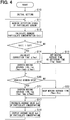
FIG. 4 is a flowchart showing a procedure of processing performed by an ECU in a second embodiment. -
FIG. 5 is a flowchart showing a procedure of processing performed by an ECU in a third embodiment. -
FIG. 6 is a flowchart showing a procedure of processing performed by an ECU in a fourth embodiment. -
FIG. 7 is a flowchart showing a procedure of processing performed by an ECU in a fifth embodiment. -
FIG. 8 is a flowchart showing a procedure of processing performed by an ECU in a sixth embodiment. -
FIG. 9 is a graph showing a relationship between a value of a current particulate concentration and a moving-average time period in a vehicular air conditioner of another embodiment. - The present embodiments will be described below with reference to the accompanying drawings. For easy understanding of the description, the same component elements in the respective drawings are provided with the same reference signs wherever possible and are not be described repeatedly.
- As shown in
FIG. 1 , avehicular air conditioner 1 in the present embodiment includes anair conditioning duct 10 and anair conditioning unit 20. Thevehicular air conditioner 1 is provided inside an instrument panel of a vehicle. - Inside the
air conditioning duct 10, anair passage 11 that introduces conditioned air for air-conditioning a vehicle interior into the vehicle interior is formed. In theair passage 11, the air flows in a direction shown by an arrow A inFIG. 1 . At a portion on an upstream side of theair conditioning duct 10 in the air flow direction A, an outsideair suction port 12 and an insideair suction port 13 are formed as portions that take air into theair passage 11 from outside theair conditioning duct 10. The outsideair suction port 12 is a portion for taking outside air which is air outside the vehicle interior into theair passage 11. The insideair suction port 13 is a portion for taking inside air which is air in the vehicle interior into theair passage 11. - At a portion in the
air conditioning duct 10 on a downstream side of the outsideair suction port 12 and the insideair suction port 13, a filter 17 is disposed. The filter 17 removes particulates such as dust included in the outside air taken in from the outsideair suction port 12 or the inside air taken in from the insideair suction port 13. - At a portion of the
air conditioning duct 10 on the downstream side in the air flow direction A, adefroster blow outlet 14, aface blow outlet 15, and afoot blow outlet 16 are formed. Thedefroster blow outlet 14 blows out the air flowing through theair conditioning duct 10 toward an inner face of a windshield of the vehicle. Theface blow outlet 15 blows out the air flowing through theair conditioning duct 10 toward a driver or an occupant in a passenger's seat. Thefoot blow outlet 16 blows out the air flowing through theair conditioning duct 10 toward feet of the driver or the occupant in the passenger's seat. - The
air conditioning unit 20 produces the conditioned air from the air introduced into theair passage 11 from the outsideair suction port 12 or the insideair suction port 13. The conditioned air is air for air-conditioning the vehicle interior. Theair conditioning unit 20 includes ablower fan 21, anevaporator 22, and aheater core 23. - The
blower fan 21 is disposed on a downstream side of the outsideair suction port 12 and the insideair suction port 13 in the air flow direction A. Theblower fan 21 rotates in accordance with a supply of electric power to thereby generate an airflow in theair passage 11. By adjusting the electric power supplied to theblower fan 21, a volume of the air flowing through theair passage 11, i.e., a volume of the conditioned air is adjusted. - The
evaporator 22 is disposed on a downstream side of theblower fan 21 in the air flow direction A. Theevaporator 22 is a component element of a refrigeration cycle (not shown). The refrigeration cycle is formed by a compressor, a condenser, and an expansion valve in addition to theevaporator 22. In the refrigeration cycle, refrigerant circulates through the compressor, the condenser, the expansion valve, and theevaporator 22 in this order. In theevaporator 22, the refrigerant flowing inside exchanges heat with the air in theair passage 11 to thereby evaporate and vaporize. Theevaporator 22 has a function of cooling the air flowing through theair passage 11 by utilizing heat of vaporization in vaporization of the refrigerant and a function of dehumidifying the air flowing through theair passage 11. - The
heater core 23 is disposed on a downstream side of theevaporator 22 in the air flow direction A. Theheater core 23 is connected to an engine (not shown) by a pipe. Engine cooling water circulates between the engine and theheater core 23 through the pipe. Theheater core 23 heats the air flowing through theair passage 11 by utilizing the engine cooling water flowing inside theheater core 23 as a heat source. - The
air conditioning unit 20 further includes an inside-outsideair switching door 24, anair mix door 25, and blowoutlet switching doors - The inside-outside
air switching door 24 opens and closes the outsideair suction port 12 and the insideair suction port 13. When the inside-outsideair switching door 24 is in an inside air introducing position shown by solid lines in the figure, the outsideair suction port 12 is closed and the insideair suction port 13 is open. In this case, thevehicular air conditioner 1 is in an inside air circulating mode in which the inside air is taken into theair passage 11 from the insideair suction port 13. When the inside-outsideair switching door 24 is in an outside air introducing position shown by broken lines in the figure, the insideair suction port 13 is closed and the outsideair suction port 12 is open. In this case, thevehicular air conditioner 1 is in an outside air introducing mode in which the outside air is taken into theair passage 11 from the outsideair suction port 12. - The
air mix door 25 adjusts a ratio between a volume of the air flowing into theheater core 23 and a volume of the air bypassing theheater core 23. To put it concretely, a position of theair mix door 25 can be adjusted between a maximum heating position shown by solid lines in the figure and a maximum cooling position shown by broken lines in the figure. When theair mix door 25 is in the maximum heating position, most of the air passing through the evaporator 22 passes through theheater core 23 and therefore a temperature of the conditioned air increases the most. When theair mix door 25 is in the maximum cooling position, most of the air passing through theevaporator 22 bypasses theheater core 23. In this case, the air cooled in theevaporator 22 flows to therespective blow outlets 14 to 16 as it is and therefore the temperature of the conditioned air decreases the most. In thevehicular air conditioner 1, by adjusting an opening of theair mix door 25 between the maximum heating position and the maximum cooling position, the temperature of the conditioned air is adjusted. - The blow
outlet switching doors 26 to 28 switch between open and closed states of thedefroster blow outlet 14, theface blow outlet 15, and thefoot blow outlet 16, respectively. When at least one of the blowoutlet switching doors 26 to 28 is brought into the open state, the conditioned air is blown out from the open blow outlet toward the vehicle interior. - Next, an electric configuration of the
vehicular air conditioner 1 will be described. Thevehicular air conditioner 1 includes acontroller 60, adisplay 61, aparticulate sensor 70, and an ECU (electronic control unit) 80. In the present embodiment, theECU 80 corresponds to a calculation section. - The
controller 60 is a unit operated by the driver to adjust a volume, a temperature, and the like of the conditioned air. Thecontroller 60 is disposed on the instrument panel of the vehicle, for example. With thecontroller 60, it is possible to select one of the outside air introducing mode and the inside air circulating mode, for example. With thecontroller 60, it is also possible to set the volume of the conditioned air, the temperature of the conditioned air, the blow outlet of the conditioned air, and the like. Thecontroller 60 outputs the pieces of control information to theECU 80. - The
display 61 is a unit that displays various kinds of information of thevehicular air conditioner 1. In the present embodiment, a display of a car navigation system of the vehicle is used as a substitute for thedisplay 61 of thevehicular air conditioner 1. It is also possible to use adedicated display 61 for thevehicular air conditioner 1. - The
particulate sensor 70 is provided to abypass path 18 formed at the portion of theair conditioning duct 10 where the filter 17 is formed. Thebypass path 18 is a portion for causing the outside air taken in from the outsideair suction port 12 or the inside air taken in from the insideair suction port 13 to flow while bypassing the filter 17. Theparticulate sensor 70 detects a concentration Cd of the particulates included in the air flowing through thebypass path 18. - To put it concretely, the
particulate sensor 70 includes a light emitting element that applies light to thebypass path 18 and a light receiving element that receives the light applied by the light emitting element, for example. The light receiving element outputs a voltage signal corresponding to the received light. Theparticulate sensor 70 outputs a voltage signal corresponding to the output voltage of the light receiving element as a detection signal Vd. An amount of light received by the light receiving element changes according to the particulate concentration Cd of the air passing through thebypass path 18. In other words, the detection signal Vd of theparticulate sensor 70 changes according to the particulate concentration Cd of the air flowing through theair conditioning duct 10. The detection signal Vd of theparticulate sensor 70 indicates a criterion voltage Voc when the particulate concentration is 0 [µg/m3] as shown inFIG. 2 . The detection signal Vd of theparticulate sensor 70 increases as the particulate concentration Cd increases and becomes a constant value when the particulate concentration Cd becomes equal to or higher than a predetermined concentration. - Detection signals of various sensors for detecting a condition of the vehicle and switches are taken into the
ECU 80. For example, as shown inFIG. 1 , an output signal of astarter switch 71 is taken into theECU 80. Thestarter switch 71 is a switch operated by the driver to start the vehicle. As thestarter switch 71, an ignition switch operated to start the engine of the vehicle and a push-button switch operated to start a hybrid car or an electric car, or the like can be used. When the driver turns on or off thestarter switch 71, thestarter switch 71 outputs a signal corresponding to the operation. - The
ECU 80 is mainly formed by a microcomputer including aCPU 81, amemory 82, and the like. TheECU 80 acquires control information from thecontroller 60 and drives theair conditioning unit 20 based on the acquired control information. In this way, the conditioned air corresponding to the control information of thecontroller 60 is produced by theair conditioning unit 20. - The
ECU 80 takes in the detection signal Vd of theparticulate sensor 70. TheECU 80 acquires pieces of information about the particulate concentration Cd based on the detection signals Vd of theparticulate sensor 70 and calculates an average value ACd of the particulate concentration by averaging the acquired particulate concentrations Cd over a moving-average time period. TheECU 80 displays the calculated average value ACd of the particulate concentration on thedisplay 61. - Next, a specific procedure of the calculation processing of the average value ACd of the particulate concentration performed by the
ECU 80 is described with reference toFIG. 3 . TheECU 80 performs the processing steps shown inFIG. 3 when thestarter switch 71 is turned on. - As shown in
FIG. 3 , theECU 80 first performs initial setting of theparticulate sensor 70 as the processing in step S10. To put it concretely, theECU 80 acquires the detection signal Vd of theparticulate sensor 70 immediately after thestarter switch 71 is turned on and stores the acquired detection signal Vd as an initial value Vdb of the detection signal Vd of theparticulate sensor 70. The reason for this is as follows. - The initial value Vdb of the detection signal Vd of the
particulate sensor 70 may change with time due to accumulation of the particulates on the light emitting element and the light receiving element. The initial value Vdb is a value of the detection signal Vd output from theparticulate sensor 70 when air not including particulates is detected. Therefore, it is necessary to calculate the particulate concentration Cd in consideration of change of the initial value Vdb of the detection signal Vd of theparticulate sensor 70 with time. - The
ECU 80 in the present embodiment acquires the detection signal Vd output from theparticulate sensor 70 immediately after thestarter switch 71 is turned on. Air is not flowing through thebypass path 18 immediately after thestarter switch 71 is turned on. Therefore, by acquiring the detection signal Vd of theparticulate sensor 70 at this time, it is possible to acquire the detection signal Vd output from theparticulate sensor 70 when the air not including the particulates is detected. TheECU 80 stores the acquired detection signal Vd in thememory 82 as the initial value Vdb. - The
ECU 80 acquires the detection signal Vd of theparticulate sensor 70 as the processing in step S11 following the processing in step S10 and calculates a current particulate concentration Cd(1) as the processing in step S12. To put it concretely, theECU 80 calculates the current particulate concentration Cd(1) based on a difference value between the detection signal Vd of theparticulate sensor 70 acquired in the processing in step S11 and the initial value Vdb stored in thememory 82. - Then, the
ECU 80 determines whether the current particulate concentration Cd(1) is higher than a predetermined threshold concentration Cd1 as the processing in step S13. The threshold concentration Cd1 is obtained in advance by an experiment or the like and stored in thememory 82 for determination of whether a large number of particulates are included in the air. As the threshold concentration Cd1, a value defined by an air quality index may be used. - In a case of a negative determination in step S13, i.e., when the current particulate concentration Cd(1) is equal to or lower than the threshold concentration Cd1, the
ECU 80 sets the moving-average time period Tma to a criterion time Tmab as the processing in step S16. The criterion time Tmab is set in advance and stored in thememory 82. - On the other hand, in a case of an affirmative determination in step S13, i.e., when the current particulate concentration Cd(1) is higher than the threshold concentration Cd1, the
ECU 80 calculates a correction time ΔTma1 based on the current particulate concentration Cd(1) as the processing in step S14. The correction time ΔTma1 is a value for correcting the moving-average time period Tma used to calculate the average value ACd of the particulate concentration. As the correction time ΔTma1, a fixed value set in advance can be used, for example. As the correction time ΔTma1, a variable value that varies according to the current particulate concentration Cd(1) can be used as well. To put it concretely, the higher the current particulate concentration Cd(1) is, the larger value theECU 80 may set as the correction time ΔTma1. - The
ECU 80 shortens the moving-average time period Tma as the processing in step S15 following step S14. To put it concretely, theECU 80 subtracts the correction time ΔTma1 from the criterion time Tmab and sets a subtracted value, "Tmab - ΔTma" as the moving-average time period Tma. - After performing the processing in step S15 or the processing in step S16, the
ECU 80 calculates the average value ACd of the particulate concentration as the processing in step S17. To put it concretely, theECU 80 calculates the average value ACd of the particulate concentration by calculating the sum of the plurality of particulate concentrations Cd(1) to Cd(n) detected by theparticulate sensor 70 for a period of the moving-average time period Tma before the present and dividing the sum by the number n of data. Here, "n" is an integer equal to or greater than 2. Therefore, when the moving-average time period Tma is shortened to "Tmab - ΔTma" in step S15, the number n of data of the particulate concentration Cd used to calculate the average value ACd of the particulate concentration is smaller than when the moving-average time period Tma is set to the criterion time Tmab in step S16. As a result, the current particulate concentration Cd(1) becomes likely to be reflected in the average value ACd of the particulate concentration. - The
ECU 80 displays the calculated average value ACd of the particulate concentration on thedisplay 61 as the processing in step S18 following the processing in step S17 and then returns to the processing in step S11. Then, theECU 80 repeatedly performs the processing steps in steps S11 to S17 at predetermined intervals. - Next, workings and effects of the
vehicular air conditioner 1 in the present embodiment are described. When the particulate concentration Cd detected by theparticulate sensor 70 changes to be equal to or higher than the threshold concentration Cd1, the moving-average time period Tma used to calculate the average value ACd of the particulate concentration becomes short. In this way, the current particulate concentration Cd(1) becomes likely to be reflected in the average value ACd of the particulate concentration and therefore it is possible to detect the particulate concentration that is closer to the actual particulate concentration in the situation. As a result, it is possible to display the more appropriate particulate concentration on thedisplay 61 to thereby suppress a user's feeling of strangeness. - Next, a second embodiment of the
vehicular air conditioner 1 is described. Differences from the first embodiment are mainly described below. - As is shown by a broken line in
FIG. 1 , thevehicular air conditioner 1 in the present embodiment further includes a window opening-closingsensor 72 that detects an open-closed state of a window of a vehicle. The window opening-closingsensor 72 detects the open-closed state of the window of the vehicle and outputs a detection signal corresponding to the detected open-closed state of the window. - The output signal of the window opening-closing
sensor 72 is taken into anECU 80. TheECU 80 acquires information about the open-closed state of the window of the vehicle based on the output signal of the window opening-closingsensor 72. - As shown in
FIG. 4 , after performing processing in step S15 or processing in step S16, theECU 80 determines whether the window of the vehicle is open as processing in step S20. In the present embodiment, the processing in step S20 corresponds to processing for determining whether an operation that causes an increase in a particulate concentration in a vehicle interior is performed. In a case of a negative determination in step S20, i.e., when the window of the vehicle is closed, theECU 80 maintains a moving-average time period Tma calculated in the processing in step S15 or the processing in step S16 as it is as processing in step S22. - In a case of an affirmative determination in step S20, i.e., when the window of the vehicle is open, the
ECU 80 determines that the particulate concentration in the vehicle interior is likely to increase. In this case, theECU 80 further shortens the moving-average time period Tma as processing in step S21. To put it concretely, theECU 80 subtracts a correction time ΔTma2 from the moving-average time period Tma calculated in the processing in step S15 or the processing in step S16 to thereby further shorten the moving-average time period Tma. The value of the correction time ΔTma2 is set in advance by an experiment or the like and stored in amemory 82. - After performing the processing in step S21 or the processing in step S22, the
ECU 80 performs processing steps in step S17 and a subsequent step. - Next, workings and effects of the
vehicular air conditioner 1 in the present embodiment are described. For example, when an inside-outsideair switching door 24 is set in an inside air introducing position, when a user opens the window of the vehicle, outside air enters the vehicle interior and therefore the particulate concentration in the vehicle interior increases. As a result, a particulate concentration in anair conditioning duct 10 increases as well. In thevehicular air conditioner 1 in the present embodiment, the moving-average time period Tma becomes even shorter in this situation. In this way, the current particulate concentration Cd(1) becomes further likely to be reflected in the average value ACd of the particulate concentration and therefore it is possible to detect the particulate concentration that is closer to an actual particulate concentration in the situation. - Next, a third embodiment of the
vehicular air conditioner 1 is described. Differences from the first embodiment are mainly described below. - As is shown by a broken line in
FIG. 1 , thevehicular air conditioner 1 in the present embodiment further includes a door opening-closingsensor 73 that detects an open-closed state of a door of a vehicle. The door opening-closingsensor 73 detects the open-closed state of the door of the vehicle and outputs a detection signal corresponding to the detected open-closed state of the door. - The output signal of the door opening-closing
sensor 73 is taken into anECU 80. TheECU 80 acquires information about the open-closed state of the door of the vehicle based on the output signal of the door opening-closingsensor 73. - As shown in
FIG. 5 , after performing processing in step S15 or processing in step S16, theECU 80 determines whether the door of the vehicle is open as processing in step S30. In the present embodiment, the processing in step S30 corresponds to processing for determining whether an operation that causes an increase in the particulate concentration in a vehicle interior is performed. In a case of a negative determination in step S30, i.e., when the door of the vehicle is closed, theECU 80 maintains a moving-average time period Tma calculated in the processing in step S15 or the processing in step S16 as it is as processing in step S32. - In a case of an affirmative determination in step S30, i.e., when the door of the vehicle is open, the
ECU 80 determines that the particulate concentration in the vehicle interior is likely to increase. In this case, theECU 80 further shortens the moving-average time period Tma as processing in step S31. To put it concretely, theECU 80 subtracts a correction time ΔTma3 from the moving-average time period Tma calculated in the processing in step S15 or the processing in step S16 to thereby further shorten the moving-average time period Tma. The value of the correction time ΔTma3 is set in advance by an experiment or the like and stored in amemory 82. - After performing the processing in step S31 or the processing in step S32, the
ECU 80 performs processing steps in step S17 and a subsequent step. - Next, workings and effects of the
vehicular air conditioner 1 in the present embodiment are described. For example, when an inside-outsideair switching door 24 is set in an inside air introducing position, when a user opens the door of the vehicle, outside air enters the vehicle interior and therefore the particulate concentration in the vehicle interior increases. As a result, a particulate concentration in anair conditioning duct 10 increases as well. In thevehicular air conditioner 1 in the present embodiment, the moving-average time period Tma becomes even shorter in this situation. In this way, the current particulate concentration Cd(1) becomes further likely to be reflected in the average value ACd of the particulate concentration and therefore it is possible to detect the particulate concentration that is closer to an actual particulate concentration in the situation. - Next, a fourth embodiment of the
vehicular air conditioner 1 is described. Differences from the first embodiment are mainly described below. - As is shown by a broken line in
FIG. 1 , thevehicular air conditioner 1 in the present embodiment includes anoccupant sensor 74 that detects whether an occupant is in a vehicle interior. Theoccupant sensor 74 detects presence or absence of the occupant in the vehicle interior and outputs a signal corresponding to the detection result. As theoccupant sensor 74, a sitting sensor that detects whether the occupant is sitting in a seat of a vehicle, an infrared sensor that detects presence or absence of the occupant in the vehicle interior by using infrared radiation, or the like can be used. - The output signal of the
occupant sensor 74 is taken into anECU 80. TheECU 80 acquires information about presence or absence of the occupant in the vehicle interior based on the output signal of theoccupant sensor 74. - As shown in
FIG. 6 , after performing processing in step S15 or processing in step S16, theECU 80 determines whether the occupant is in the vehicle interior as processing in step S40. In a case of a negative determination in step S40, i.e., when no occupant is in the vehicle interior, theECU 80 maintains a moving-average time period Tma calculated in the processing in step S15 or the processing in step S16 as processing in step S42. - In a case of an affirmative determination in step S40, i.e., when the occupant is in the vehicle interior, the
ECU 80 determines that the particulate concentration in the vehicle interior is likely to increase. In this case, theECU 80 further shortens the moving-average time period Tma as processing in step S41. To put it concretely, theECU 80 subtracts a correction time ΔTma4 from the moving-average time period Tma calculated in the processing in step S15 or the processing in step S16 to thereby further shorten the moving-average time period Tma. The value of the correction time ΔTma4 is set in advance by an experiment or the like and stored in amemory 82. The value of the correction time ΔTma4 may be a value that is variable according to the number of occupants in the vehicle interior. To put it concretely, theECU 80 may increase the value of the correction time ΔTma4 as the number of occupants in the vehicle interior increases. - After performing the processing in step S41 or the processing in step S42, the
ECU 80 performs processing steps in step S17 and a subsequent step. - Next, workings and effects of the
vehicular air conditioner 1 in the present embodiment are described. When the occupant is in the vehicle interior, the particulates adhering to clothes or the like of the occupant fly in the vehicle interior, which increases the particulate concentration in the vehicle interior. In this situation, when the inside-outsideair switching door 24 is set in an inside air introducing position, a particulate concentration in anair conditioning duct 10 increases as well. In thevehicular air conditioner 1 in the present embodiment, the moving-average time period Tma becomes even shorter in this situation. In this way, the current particulate concentration Cd(1) becomes further likely to be reflected in the average value ACd of the particulate concentration and therefore it is possible to detect the particulate concentration that is closer to an actual particulate concentration in the situation. - Next, a fifth embodiment of the
vehicular air conditioner 1 is described. Differences from the first embodiment are mainly described below. - As is shown by a broken line in
FIG. 1 , anECU 80 in the present embodiment is radio-communicably connected to aserver 75 that manages information about particulate concentration Cda in the atmosphere via a network line. TheECU 80 can acquire the information about the current particulate concentration Cda in the atmosphere by way of communication with theserver 75. In the present embodiment, theserver 75 corresponds to an external device. - As shown in
FIG. 7 , after performing processing in step S15 or processing in step S16, theECU 80 acquires the information about the current particulate concentration Cda in the atmosphere from theserver 75 as processing in step S50. Then, theECU 80 determines whether the current particulate concentration Cda in the atmosphere is higher than a predetermined threshold concentration Cda1 as processing in step S51. In the present embodiment, a threshold concentration Cd1 corresponds to a first threshold concentration and the threshold concentration Cda1 corresponds to a second threshold concentration. - In a case of a negative determination in step S51, i.e., when the current particulate concentration Cda in the atmosphere is equal to or lower than the predetermined threshold concentration Cda1, the
ECU 80 maintains a moving-average time period Tma calculated in the processing in step S15 or the processing in step S16 as it is as processing in step S53. - In a case of an affirmative determination in step S51, i.e., when the current particulate concentration Cda in the air is higher than the threshold concentration Cda1, the
ECU 80 further shortens the moving-average time period Tma as processing in step S52. To put it concretely, theECU 80 subtracts a correction time ΔTma5 from the moving-average time period Tma calculated in the processing in step S15 or the processing in step S16 to thereby further shorten the moving-average time period Tma. The value of the correction time ΔTma5 is set in advance by an experiment or the like and stored in amemory 82. The value of the correction time ΔTma5 may be a value that is variable according to the particulate concentration Cda in the atmosphere. To put it concretely, the value of the correction time ΔTma5 may be increased as the particulate concentration Cda in the atmosphere increases. - After performing the processing in step S52 or the processing in step S53, the
ECU 80 performs processing steps in step S17 and a subsequent step. - Next, workings and effects of the
vehicular air conditioner 1 in the present embodiment are described. When the particulate concentration Cda in the atmosphere is high, particulates in the atmosphere are likely to enter anair conditioning duct 10 and therefore a particulate concentration in theair conditioning duct 10 may increase. In this situation, the moving-average time period Tma becomes even shorter. As a result, the current particulate concentration Cd(1) becomes further likely to be reflected in an average value ACd of the particulate concentration and therefore it is possible to detect the particulate concentration that is closer to an actual particulate concentration in the situation. - Next, a sixth embodiment of the
vehicular air conditioner 1 is described. Differences from the first embodiment are mainly described below. - As shown in
FIG. 8 , after performing processing in step S15 or processing in step S16, theECU 80 in the present embodiment determines whether outside air is introduced into anair conditioning duct 10 as processing in step S60. To put it concretely, theECU 80 determines that the outside air is introduced into theair conditioning duct 10 based on a fact that an inside-outsideair switching door 24 is in an outside air introducing position. In the present embodiment, the processing in step S60 corresponds to processing for determining whether an operation that causes an increase in a particulate concentration in a vehicle interior is performed. In a case of a negative determination in step S60, i.e., when the inside air is introduced into theair conditioning duct 10, theECU 80 maintains a moving-average time period Tma calculated in the processing in step S15 or the processing in step S16 as it is as processing in step S62. - In a case of an affirmative determination in step S60, i.e., when the outside air is introduced into the
air conditioning duct 10, theECU 80 determines that the particulate concentration in the vehicle interior is likely to increase. In this case, theECU 80 further shortens the moving-average time period Tma as processing in step S61. To put it concretely, theECU 80 subtracts a correction time ΔTma6 from the moving-average time period Tma calculated in the processing in step S15 or the processing in step S16 to thereby further shorten the moving-average time period Tma. The value of the correction time ΔTma6 is set in advance by an experiment or the like and stored in amemory 82. - After performing the processing in step S61 or the processing in step S62, the
ECU 80 performs processing steps in step S17 and a subsequent step. - Next, workings and effects of the
vehicular air conditioner 1 in the present embodiment are described. For example, when the inside-outsideair switching door 24 is set in the outside air introducing position, particulates in the atmosphere enter theair conditioning duct 10 and therefore a particulate concentration in theair conditioning duct 10 increases as well. In thevehicular air conditioner 1 in the present embodiment, the moving-average time period Tma becomes even shorter in this situation. In this way, the current particulate concentration Cd(1) becomes further likely to be reflected in the average value ACd of the particulate concentration and therefore it is possible to detect the particulate concentration that is closer to an actual particulate concentration in the situation. - The respective embodiments may be carried out in the following modes.
- In the
vehicular air conditioner 1 in the fifth embodiment, an appropriate external device which is not theserver 75 may be used as the external device for managing the information about the particulate concentration in the atmosphere. - As shown in
FIG. 9 , a threshold concentration Cd1 may have hysteresis with respect to a current particulate concentration Cd(1). To put it concretely, when the current particulate concentration Cd(1) increases, the threshold concentration Cd1 is set to a first set value Cd11. When the current particulate concentration Cd(1) decreases, the threshold concentration Cd1 is set to a second set value Cd12. With this configuration, it is possible to suppress variation in the threshold concentration Cd1 when the current particulate concentration Cd(1) varies around the set values Cd11, Cd12. As a result, it is possible to suppress variation in an average value ACd of the particulate concentration displayed on adisplay 61. - Means and/or functions which the
ECU 80 provides may be provided by a software stored in a tangible memory and a computer for running the software, a software only, a hardware only, or a combination of them. When theECU 80 is provided by an electronic circuit which is a hardware, for example, theECU 80 may be provided by a digital circuit or an analog circuit including a large number of logic circuits. - The present embodiments have been described above with reference to concrete examples. However, the present disclosure is not limited to the concrete examples. The concrete examples modified in design by a person skilled in the art where necessary are included in the scope of the present disclosure, if the modified concrete examples show characteristics of the present disclosure. Respective elements in the above-described respective concrete examples and arrangements, conditions, shapes, and the like of the elements are not limited to those shown in the examples and can be changed where necessary. The respective elements in the above-described respective concrete examples can be combined in different ways where necessary unless a technical contradiction arises.
Claims (8)
- A vehicular air conditioner (1) that air-conditions a vehicle interior by blowing air through an air conditioning duct (10) into the vehicle interior, the vehicular air conditioner (1) comprising:a particulate sensor (70) that detects a particulate concentration in the air flowing through the air conditioning duct; anda calculation section (80) that calculates an average value of the particulate concentration by averaging the particulate concentrations detected by the particulate sensor over a moving-average time period, whereinwhen a current particulate concentration detected by the particulate sensor is higher than a predetermined threshold concentration, the calculation section makes the moving-average time period shorter than the moving-average time period used when the current particulate concentration is equal to or lower than the threshold concentration.
- The vehicular air conditioner according to claim 1, wherein,
when the current particulate concentration is higher than the threshold concentration, the calculation section determines whether an operation that causes an increase in the particulate concentration in the vehicle interior is performed for a vehicle, and
the calculation section makes the moving-average time period even shorter when the operation that causes an increase in the particulate concentration in the vehicle interior is determined to be performed for the vehicle. - The vehicular air conditioner according to claim 2 further comprising a door opening-closing sensor (73) that detects an open-closed state of a vehicle door, wherein
the calculation section determines that the operation that causes an increase in the particulate concentration in the vehicle interior is performed for the vehicle when the vehicle door is determined to be open based on the open-closed state of the vehicle door detected by the door opening-closing sensor. - The vehicular air conditioner according to claim 2 further comprising a window opening-closing sensor (72) that detects an open-closed state of a vehicle window, wherein
the calculation section determines that the operation that causes an increase in the particulate concentration in the vehicle interior is performed for the vehicle when the window is determined to be open based on the open-closed state of the window detected by the window opening-closing sensor. - The vehicular air conditioner according to claim 2, wherein the calculation section determines that the operation that causes an increase in the particulate concentration in the vehicle interior is performed for the vehicle when an inside-outside air switching door of the vehicular air conditioner is positioned in an outside air introducing position.
- The vehicular air conditioner according to claim 1 further comprising an occupant sensor (74) that detects presence or absence of an occupant in the vehicle interior, wherein
when the current particulate concentration is higher than the threshold concentration, the calculation section determines whether the occupant is in the vehicle interior with the occupant sensor, and
the calculation section makes the moving-average time period even shorter when the occupant is determined to be in the vehicle interior. - The vehicular air conditioner according to claim 1, wherein
the threshold concentration is defined as a first threshold concentration,
when the current particulate concentration is higher than the threshold concentration, the calculation section acquires information about a particulate concentration in atmosphere from an external device, and
the calculation section makes the moving-average time period even shorter when the particulate concentration in the atmosphere is higher than a predetermined second threshold concentration. - The vehicular air conditioner according to any one of claims 1 to 7, wherein the threshold concentration has hysteresis with respect to the current particulate concentration.
Applications Claiming Priority (2)
| Application Number | Priority Date | Filing Date | Title |
|---|---|---|---|
| JP2016234915A JP6631487B2 (en) | 2016-12-02 | 2016-12-02 | Vehicle air conditioner |
| PCT/JP2017/038168 WO2018100921A1 (en) | 2016-12-02 | 2017-10-23 | Vehicular air conditioning device |
Publications (3)
| Publication Number | Publication Date |
|---|---|
| EP3549801A1 true EP3549801A1 (en) | 2019-10-09 |
| EP3549801A4 EP3549801A4 (en) | 2019-12-11 |
| EP3549801B1 EP3549801B1 (en) | 2020-05-13 |
Family
ID=62241562
Family Applications (1)
| Application Number | Title | Priority Date | Filing Date |
|---|---|---|---|
| EP17875439.6A Active EP3549801B1 (en) | 2016-12-02 | 2017-10-23 | Vehicular air conditioning device |
Country Status (4)
| Country | Link |
|---|---|
| EP (1) | EP3549801B1 (en) |
| JP (1) | JP6631487B2 (en) |
| CN (1) | CN110049888B (en) |
| WO (1) | WO2018100921A1 (en) |
Families Citing this family (4)
| Publication number | Priority date | Publication date | Assignee | Title |
|---|---|---|---|---|
| JP7234619B2 (en) * | 2018-12-20 | 2023-03-08 | 株式会社デンソー | vehicle air conditioner |
| JP2020118453A (en) * | 2019-01-18 | 2020-08-06 | 株式会社デンソー | PM sensor |
| JPWO2022176727A1 (en) * | 2021-02-16 | 2022-08-25 | ||
| CN115046895B (en) * | 2022-06-08 | 2025-01-24 | 中煤科工集团重庆研究院有限公司 | Individual respirable dust concentration detection device and method |
Family Cites Families (18)
| Publication number | Priority date | Publication date | Assignee | Title |
|---|---|---|---|---|
| FR2541945B1 (en) * | 1983-03-04 | 1987-08-21 | Loubet Eliane | AIR CONDITIONER FOR WORKING CABINS IN POLLUTED ATMOSPHERE |
| JPS61139509A (en) * | 1984-12-10 | 1986-06-26 | Fujitsu Ten Ltd | Forced ventilating device for vehicle |
| US5062065A (en) * | 1989-10-06 | 1991-10-29 | Leopold Kostal Gmbh & Co., Kg | Environmental sensing and ventilation control system with compensation for sensor characteristics |
| DE4106078A1 (en) * | 1991-02-27 | 1992-09-03 | Daimler Benz Ag | DEVICE OR METHOD FOR CONTROLLING VENTILATION OF AN INTERIOR, IN PARTICULAR WITH MOTOR VEHICLES |
| US6099609A (en) * | 1998-07-30 | 2000-08-08 | 3M Innovative Properties Company | Moving sorbent filter device |
| FR2806037B1 (en) * | 2000-03-07 | 2002-11-15 | Valeo Electronique | DEVICE FOR DETECTING A RISK OF FOGTING A MOTOR VEHICLE WINDOW, AND INSTALLATION COMPRISING SUCH A DEVICE |
| JP4317640B2 (en) * | 2000-03-31 | 2009-08-19 | 日本特殊陶業株式会社 | Control system |
| KR100477078B1 (en) * | 2000-05-17 | 2005-03-18 | 한국델파이주식회사 | Method for judgement pollution of the by gas sensor |
| US6283849B1 (en) * | 2000-10-05 | 2001-09-04 | Specific Cruise Systems, Inc. | Vehicle filtration control system |
| JP4470351B2 (en) | 2001-06-12 | 2010-06-02 | パナソニック電工株式会社 | Dust sensor and air purifier |
| JP4074634B2 (en) * | 2003-09-09 | 2008-04-09 | エフアイエス株式会社 | Gas detector |
| JP4325494B2 (en) * | 2004-06-21 | 2009-09-02 | トヨタ自動車株式会社 | Dust reduction device |
| JP6242214B2 (en) * | 2010-11-01 | 2017-12-06 | コーニンクレッカ フィリップス エヌ ヴェKoninklijke Philips N.V. | How to calibrate an air sensor |
| CN102963320B (en) * | 2012-11-29 | 2015-06-10 | 长城汽车股份有限公司 | Intelligent control method for car window |
| CN103604181B (en) * | 2013-11-25 | 2016-09-14 | 上海竞胜国际贸易有限公司 | A kind of power-economizing method of novel on-vehicle energy saver |
| US9729945B2 (en) * | 2014-09-03 | 2017-08-08 | Oberon, Inc. | Environmental monitor device with database |
| CN104566663A (en) * | 2014-12-18 | 2015-04-29 | 南京协众汽车空调集团有限公司 | Automobile environment-friendly air conditioning system based on PM2.5 (Particulate Matter) monitoring and control method |
| CN104713598A (en) * | 2015-03-11 | 2015-06-17 | 上海途业科技发展有限公司 | Vehicle-mounted air quality monitoring device and method |
-
2016
- 2016-12-02 JP JP2016234915A patent/JP6631487B2/en active Active
-
2017
- 2017-10-23 EP EP17875439.6A patent/EP3549801B1/en active Active
- 2017-10-23 WO PCT/JP2017/038168 patent/WO2018100921A1/en not_active Ceased
- 2017-10-23 CN CN201780074218.3A patent/CN110049888B/en not_active Expired - Fee Related
Also Published As
| Publication number | Publication date |
|---|---|
| EP3549801B1 (en) | 2020-05-13 |
| EP3549801A4 (en) | 2019-12-11 |
| WO2018100921A1 (en) | 2018-06-07 |
| JP2018090083A (en) | 2018-06-14 |
| JP6631487B2 (en) | 2020-01-15 |
| CN110049888B (en) | 2022-07-05 |
| CN110049888A (en) | 2019-07-23 |
Similar Documents
| Publication | Publication Date | Title |
|---|---|---|
| EP3549801B1 (en) | Vehicular air conditioning device | |
| CN108430814B (en) | Air conditioner for vehicle | |
| US10017029B2 (en) | Air conditioning system for motor vehicles | |
| EP3572255A1 (en) | Vehicle air conditioning apparatus | |
| JP6565837B2 (en) | Air conditioner for vehicles | |
| US20150328961A1 (en) | Smell generation time predicting device and smell generation time predicting method using the same | |
| KR100534896B1 (en) | Moisture removing system for automobile air-conditioning system and method for controlling the same | |
| JP2016210382A (en) | Vehicular air conditioner | |
| CN110290954B (en) | Air conditioner for vehicle | |
| JP2010167895A (en) | Air conditioner for vehicle | |
| JP6583245B2 (en) | Air conditioner for vehicles | |
| JP2009090906A (en) | CO2 concentration detection system | |
| JP7234784B2 (en) | Vehicle air conditioning controller | |
| JP3201125B2 (en) | Vehicle air conditioner | |
| WO2017082074A1 (en) | Air conditioning device for vehicle | |
| JP6372110B2 (en) | Air conditioner for vehicles | |
| KR20100022693A (en) | The control method of air conditioner for vehicle | |
| JP7613822B2 (en) | Vehicle air conditioning system | |
| JP6665480B2 (en) | Control device | |
| JP2008137532A (en) | Air conditioning control device for vehicles | |
| KR20090072615A (en) | Control device of vehicle air conditioning system | |
| JP7038464B2 (en) | Vehicle air conditioning control device | |
| KR100363000B1 (en) | Method and system for dual air conditioning control for an automobile | |
| JP2018176968A (en) | Air conditioning controller | |
| KR20150141818A (en) | Method for controlling hvac of vehicle and apparatus thereof |
Legal Events
| Date | Code | Title | Description |
|---|---|---|---|
| STAA | Information on the status of an ep patent application or granted ep patent |
Free format text: STATUS: THE INTERNATIONAL PUBLICATION HAS BEEN MADE |
|
| PUAI | Public reference made under article 153(3) epc to a published international application that has entered the european phase |
Free format text: ORIGINAL CODE: 0009012 |
|
| STAA | Information on the status of an ep patent application or granted ep patent |
Free format text: STATUS: REQUEST FOR EXAMINATION WAS MADE |
|
| 17P | Request for examination filed |
Effective date: 20190531 |
|
| AK | Designated contracting states |
Kind code of ref document: A1 Designated state(s): AL AT BE BG CH CY CZ DE DK EE ES FI FR GB GR HR HU IE IS IT LI LT LU LV MC MK MT NL NO PL PT RO RS SE SI SK SM TR |
|
| AX | Request for extension of the european patent |
Extension state: BA ME |
|
| A4 | Supplementary search report drawn up and despatched |
Effective date: 20191113 |
|
| RIC1 | Information provided on ipc code assigned before grant |
Ipc: B60H 1/00 20060101ALI20191107BHEP Ipc: B60H 3/06 20060101ALI20191107BHEP Ipc: B60H 3/00 20060101ALI20191107BHEP Ipc: G01N 15/06 20060101ALI20191107BHEP Ipc: B60H 1/24 20060101AFI20191107BHEP |
|
| GRAP | Despatch of communication of intention to grant a patent |
Free format text: ORIGINAL CODE: EPIDOSNIGR1 |
|
| STAA | Information on the status of an ep patent application or granted ep patent |
Free format text: STATUS: GRANT OF PATENT IS INTENDED |
|
| INTG | Intention to grant announced |
Effective date: 20191213 |
|
| DAV | Request for validation of the european patent (deleted) | ||
| DAX | Request for extension of the european patent (deleted) | ||
| GRAS | Grant fee paid |
Free format text: ORIGINAL CODE: EPIDOSNIGR3 |
|
| GRAA | (expected) grant |
Free format text: ORIGINAL CODE: 0009210 |
|
| STAA | Information on the status of an ep patent application or granted ep patent |
Free format text: STATUS: THE PATENT HAS BEEN GRANTED |
|
| AK | Designated contracting states |
Kind code of ref document: B1 Designated state(s): AL AT BE BG CH CY CZ DE DK EE ES FI FR GB GR HR HU IE IS IT LI LT LU LV MC MK MT NL NO PL PT RO RS SE SI SK SM TR |
|
| REG | Reference to a national code |
Ref country code: GB Ref legal event code: FG4D |
|
| REG | Reference to a national code |
Ref country code: CH Ref legal event code: EP |
|
| REG | Reference to a national code |
Ref country code: DE Ref legal event code: R096 Ref document number: 602017016907 Country of ref document: DE |
|
| REG | Reference to a national code |
Ref country code: AT Ref legal event code: REF Ref document number: 1269793 Country of ref document: AT Kind code of ref document: T Effective date: 20200615 |
|
| REG | Reference to a national code |
Ref country code: LT Ref legal event code: MG4D |
|
| REG | Reference to a national code |
Ref country code: NL Ref legal event code: MP Effective date: 20200513 |
|
| PG25 | Lapsed in a contracting state [announced via postgrant information from national office to epo] |
Ref country code: PT Free format text: LAPSE BECAUSE OF FAILURE TO SUBMIT A TRANSLATION OF THE DESCRIPTION OR TO PAY THE FEE WITHIN THE PRESCRIBED TIME-LIMIT Effective date: 20200914 Ref country code: LT Free format text: LAPSE BECAUSE OF FAILURE TO SUBMIT A TRANSLATION OF THE DESCRIPTION OR TO PAY THE FEE WITHIN THE PRESCRIBED TIME-LIMIT Effective date: 20200513 Ref country code: FI Free format text: LAPSE BECAUSE OF FAILURE TO SUBMIT A TRANSLATION OF THE DESCRIPTION OR TO PAY THE FEE WITHIN THE PRESCRIBED TIME-LIMIT Effective date: 20200513 Ref country code: GR Free format text: LAPSE BECAUSE OF FAILURE TO SUBMIT A TRANSLATION OF THE DESCRIPTION OR TO PAY THE FEE WITHIN THE PRESCRIBED TIME-LIMIT Effective date: 20200814 Ref country code: IS Free format text: LAPSE BECAUSE OF FAILURE TO SUBMIT A TRANSLATION OF THE DESCRIPTION OR TO PAY THE FEE WITHIN THE PRESCRIBED TIME-LIMIT Effective date: 20200913 Ref country code: SE Free format text: LAPSE BECAUSE OF FAILURE TO SUBMIT A TRANSLATION OF THE DESCRIPTION OR TO PAY THE FEE WITHIN THE PRESCRIBED TIME-LIMIT Effective date: 20200513 Ref country code: NO Free format text: LAPSE BECAUSE OF FAILURE TO SUBMIT A TRANSLATION OF THE DESCRIPTION OR TO PAY THE FEE WITHIN THE PRESCRIBED TIME-LIMIT Effective date: 20200813 |
|
| PG25 | Lapsed in a contracting state [announced via postgrant information from national office to epo] |
Ref country code: BG Free format text: LAPSE BECAUSE OF FAILURE TO SUBMIT A TRANSLATION OF THE DESCRIPTION OR TO PAY THE FEE WITHIN THE PRESCRIBED TIME-LIMIT Effective date: 20200813 Ref country code: HR Free format text: LAPSE BECAUSE OF FAILURE TO SUBMIT A TRANSLATION OF THE DESCRIPTION OR TO PAY THE FEE WITHIN THE PRESCRIBED TIME-LIMIT Effective date: 20200513 Ref country code: RS Free format text: LAPSE BECAUSE OF FAILURE TO SUBMIT A TRANSLATION OF THE DESCRIPTION OR TO PAY THE FEE WITHIN THE PRESCRIBED TIME-LIMIT Effective date: 20200513 Ref country code: LV Free format text: LAPSE BECAUSE OF FAILURE TO SUBMIT A TRANSLATION OF THE DESCRIPTION OR TO PAY THE FEE WITHIN THE PRESCRIBED TIME-LIMIT Effective date: 20200513 |
|
| REG | Reference to a national code |
Ref country code: AT Ref legal event code: MK05 Ref document number: 1269793 Country of ref document: AT Kind code of ref document: T Effective date: 20200513 |
|
| PG25 | Lapsed in a contracting state [announced via postgrant information from national office to epo] |
Ref country code: AL Free format text: LAPSE BECAUSE OF FAILURE TO SUBMIT A TRANSLATION OF THE DESCRIPTION OR TO PAY THE FEE WITHIN THE PRESCRIBED TIME-LIMIT Effective date: 20200513 Ref country code: NL Free format text: LAPSE BECAUSE OF FAILURE TO SUBMIT A TRANSLATION OF THE DESCRIPTION OR TO PAY THE FEE WITHIN THE PRESCRIBED TIME-LIMIT Effective date: 20200513 |
|
| PG25 | Lapsed in a contracting state [announced via postgrant information from national office to epo] |
Ref country code: RO Free format text: LAPSE BECAUSE OF FAILURE TO SUBMIT A TRANSLATION OF THE DESCRIPTION OR TO PAY THE FEE WITHIN THE PRESCRIBED TIME-LIMIT Effective date: 20200513 Ref country code: IT Free format text: LAPSE BECAUSE OF FAILURE TO SUBMIT A TRANSLATION OF THE DESCRIPTION OR TO PAY THE FEE WITHIN THE PRESCRIBED TIME-LIMIT Effective date: 20200513 Ref country code: EE Free format text: LAPSE BECAUSE OF FAILURE TO SUBMIT A TRANSLATION OF THE DESCRIPTION OR TO PAY THE FEE WITHIN THE PRESCRIBED TIME-LIMIT Effective date: 20200513 Ref country code: AT Free format text: LAPSE BECAUSE OF FAILURE TO SUBMIT A TRANSLATION OF THE DESCRIPTION OR TO PAY THE FEE WITHIN THE PRESCRIBED TIME-LIMIT Effective date: 20200513 Ref country code: DK Free format text: LAPSE BECAUSE OF FAILURE TO SUBMIT A TRANSLATION OF THE DESCRIPTION OR TO PAY THE FEE WITHIN THE PRESCRIBED TIME-LIMIT Effective date: 20200513 Ref country code: SM Free format text: LAPSE BECAUSE OF FAILURE TO SUBMIT A TRANSLATION OF THE DESCRIPTION OR TO PAY THE FEE WITHIN THE PRESCRIBED TIME-LIMIT Effective date: 20200513 Ref country code: ES Free format text: LAPSE BECAUSE OF FAILURE TO SUBMIT A TRANSLATION OF THE DESCRIPTION OR TO PAY THE FEE WITHIN THE PRESCRIBED TIME-LIMIT Effective date: 20200513 Ref country code: CZ Free format text: LAPSE BECAUSE OF FAILURE TO SUBMIT A TRANSLATION OF THE DESCRIPTION OR TO PAY THE FEE WITHIN THE PRESCRIBED TIME-LIMIT Effective date: 20200513 |
|
| REG | Reference to a national code |
Ref country code: DE Ref legal event code: R097 Ref document number: 602017016907 Country of ref document: DE |
|
| PG25 | Lapsed in a contracting state [announced via postgrant information from national office to epo] |
Ref country code: PL Free format text: LAPSE BECAUSE OF FAILURE TO SUBMIT A TRANSLATION OF THE DESCRIPTION OR TO PAY THE FEE WITHIN THE PRESCRIBED TIME-LIMIT Effective date: 20200513 Ref country code: SK Free format text: LAPSE BECAUSE OF FAILURE TO SUBMIT A TRANSLATION OF THE DESCRIPTION OR TO PAY THE FEE WITHIN THE PRESCRIBED TIME-LIMIT Effective date: 20200513 |
|
| PLBE | No opposition filed within time limit |
Free format text: ORIGINAL CODE: 0009261 |
|
| STAA | Information on the status of an ep patent application or granted ep patent |
Free format text: STATUS: NO OPPOSITION FILED WITHIN TIME LIMIT |
|
| 26N | No opposition filed |
Effective date: 20210216 |
|
| REG | Reference to a national code |
Ref country code: CH Ref legal event code: PL |
|
| PG25 | Lapsed in a contracting state [announced via postgrant information from national office to epo] |
Ref country code: MC Free format text: LAPSE BECAUSE OF FAILURE TO SUBMIT A TRANSLATION OF THE DESCRIPTION OR TO PAY THE FEE WITHIN THE PRESCRIBED TIME-LIMIT Effective date: 20200513 Ref country code: LU Free format text: LAPSE BECAUSE OF NON-PAYMENT OF DUE FEES Effective date: 20201023 |
|
| REG | Reference to a national code |
Ref country code: BE Ref legal event code: MM Effective date: 20201031 |
|
| PG25 | Lapsed in a contracting state [announced via postgrant information from national office to epo] |
Ref country code: FR Free format text: LAPSE BECAUSE OF NON-PAYMENT OF DUE FEES Effective date: 20201031 |
|
| PG25 | Lapsed in a contracting state [announced via postgrant information from national office to epo] |
Ref country code: BE Free format text: LAPSE BECAUSE OF NON-PAYMENT OF DUE FEES Effective date: 20201031 Ref country code: CH Free format text: LAPSE BECAUSE OF NON-PAYMENT OF DUE FEES Effective date: 20201031 Ref country code: LI Free format text: LAPSE BECAUSE OF NON-PAYMENT OF DUE FEES Effective date: 20201031 |
|
| PG25 | Lapsed in a contracting state [announced via postgrant information from national office to epo] |
Ref country code: IE Free format text: LAPSE BECAUSE OF NON-PAYMENT OF DUE FEES Effective date: 20201023 |
|
| PG25 | Lapsed in a contracting state [announced via postgrant information from national office to epo] |
Ref country code: TR Free format text: LAPSE BECAUSE OF FAILURE TO SUBMIT A TRANSLATION OF THE DESCRIPTION OR TO PAY THE FEE WITHIN THE PRESCRIBED TIME-LIMIT Effective date: 20200513 Ref country code: MT Free format text: LAPSE BECAUSE OF FAILURE TO SUBMIT A TRANSLATION OF THE DESCRIPTION OR TO PAY THE FEE WITHIN THE PRESCRIBED TIME-LIMIT Effective date: 20200513 Ref country code: CY Free format text: LAPSE BECAUSE OF FAILURE TO SUBMIT A TRANSLATION OF THE DESCRIPTION OR TO PAY THE FEE WITHIN THE PRESCRIBED TIME-LIMIT Effective date: 20200513 |
|
| GBPC | Gb: european patent ceased through non-payment of renewal fee |
Effective date: 20211023 |
|
| PG25 | Lapsed in a contracting state [announced via postgrant information from national office to epo] |
Ref country code: MK Free format text: LAPSE BECAUSE OF FAILURE TO SUBMIT A TRANSLATION OF THE DESCRIPTION OR TO PAY THE FEE WITHIN THE PRESCRIBED TIME-LIMIT Effective date: 20200513 |
|
| PG25 | Lapsed in a contracting state [announced via postgrant information from national office to epo] |
Ref country code: GB Free format text: LAPSE BECAUSE OF NON-PAYMENT OF DUE FEES Effective date: 20211023 |
|
| PG25 | Lapsed in a contracting state [announced via postgrant information from national office to epo] |
Ref country code: SI Free format text: LAPSE BECAUSE OF FAILURE TO SUBMIT A TRANSLATION OF THE DESCRIPTION OR TO PAY THE FEE WITHIN THE PRESCRIBED TIME-LIMIT Effective date: 20200513 |
|
| PGFP | Annual fee paid to national office [announced via postgrant information from national office to epo] |
Ref country code: DE Payment date: 20231020 Year of fee payment: 7 |
|
| REG | Reference to a national code |
Ref country code: DE Ref legal event code: R119 Ref document number: 602017016907 Country of ref document: DE |
|
| PG25 | Lapsed in a contracting state [announced via postgrant information from national office to epo] |
Ref country code: DE Free format text: LAPSE BECAUSE OF NON-PAYMENT OF DUE FEES Effective date: 20250501 |