EP3549718A2 - Verfahren und vorrichtung zur endbearbeitung eines internen kanals einer komponente - Google Patents
Verfahren und vorrichtung zur endbearbeitung eines internen kanals einer komponente Download PDFInfo
- Publication number
- EP3549718A2 EP3549718A2 EP19161477.5A EP19161477A EP3549718A2 EP 3549718 A2 EP3549718 A2 EP 3549718A2 EP 19161477 A EP19161477 A EP 19161477A EP 3549718 A2 EP3549718 A2 EP 3549718A2
- Authority
- EP
- European Patent Office
- Prior art keywords
- fluid
- component
- internal channel
- flow
- cavitation
- Prior art date
- Legal status (The legal status is an assumption and is not a legal conclusion. Google has not performed a legal analysis and makes no representation as to the accuracy of the status listed.)
- Withdrawn
Links
- 238000000034 method Methods 0.000 title claims abstract description 31
- 239000012530 fluid Substances 0.000 claims abstract description 86
- 230000000694 effects Effects 0.000 claims abstract description 10
- 238000011144 upstream manufacturing Methods 0.000 claims description 33
- 238000010438 heat treatment Methods 0.000 claims description 23
- 239000002245 particle Substances 0.000 claims description 23
- 230000003628 erosive effect Effects 0.000 claims description 21
- 238000004519 manufacturing process Methods 0.000 claims description 9
- 238000009499 grossing Methods 0.000 claims description 6
- 238000005299 abrasion Methods 0.000 claims description 5
- 239000000654 additive Substances 0.000 claims description 5
- 230000000996 additive effect Effects 0.000 claims description 5
- 239000000155 melt Substances 0.000 description 12
- 239000007789 gas Substances 0.000 description 6
- 208000035874 Excoriation Diseases 0.000 description 4
- 238000009825 accumulation Methods 0.000 description 3
- 238000002485 combustion reaction Methods 0.000 description 3
- 239000000446 fuel Substances 0.000 description 3
- 230000001141 propulsive effect Effects 0.000 description 3
- 239000002033 PVDF binder Substances 0.000 description 2
- 238000007730 finishing process Methods 0.000 description 2
- 239000000463 material Substances 0.000 description 2
- 229920002981 polyvinylidene fluoride Polymers 0.000 description 2
- 230000035939 shock Effects 0.000 description 2
- 229910052582 BN Inorganic materials 0.000 description 1
- PZNSFCLAULLKQX-UHFFFAOYSA-N Boron nitride Chemical compound N#B PZNSFCLAULLKQX-UHFFFAOYSA-N 0.000 description 1
- 239000003082 abrasive agent Substances 0.000 description 1
- PNEYBMLMFCGWSK-UHFFFAOYSA-N aluminium oxide Inorganic materials [O-2].[O-2].[O-2].[Al+3].[Al+3] PNEYBMLMFCGWSK-UHFFFAOYSA-N 0.000 description 1
- 229910052586 apatite Inorganic materials 0.000 description 1
- 230000015572 biosynthetic process Effects 0.000 description 1
- 239000013590 bulk material Substances 0.000 description 1
- 230000006835 compression Effects 0.000 description 1
- 238000007906 compression Methods 0.000 description 1
- 238000011109 contamination Methods 0.000 description 1
- 238000005755 formation reaction Methods 0.000 description 1
- 239000011019 hematite Substances 0.000 description 1
- 229910052595 hematite Inorganic materials 0.000 description 1
- 230000002706 hydrostatic effect Effects 0.000 description 1
- 230000003993 interaction Effects 0.000 description 1
- LIKBJVNGSGBSGK-UHFFFAOYSA-N iron(3+);oxygen(2-) Chemical compound [O-2].[O-2].[O-2].[Fe+3].[Fe+3] LIKBJVNGSGBSGK-UHFFFAOYSA-N 0.000 description 1
- 238000003754 machining Methods 0.000 description 1
- 239000000203 mixture Substances 0.000 description 1
- 238000012544 monitoring process Methods 0.000 description 1
- VSIIXMUUUJUKCM-UHFFFAOYSA-D pentacalcium;fluoride;triphosphate Chemical compound [F-].[Ca+2].[Ca+2].[Ca+2].[Ca+2].[Ca+2].[O-]P([O-])([O-])=O.[O-]P([O-])([O-])=O.[O-]P([O-])([O-])=O VSIIXMUUUJUKCM-UHFFFAOYSA-D 0.000 description 1
- 239000010453 quartz Substances 0.000 description 1
- 230000000717 retained effect Effects 0.000 description 1
- 238000005070 sampling Methods 0.000 description 1
- HBMJWWWQQXIZIP-UHFFFAOYSA-N silicon carbide Chemical compound [Si+]#[C-] HBMJWWWQQXIZIP-UHFFFAOYSA-N 0.000 description 1
- 229910010271 silicon carbide Inorganic materials 0.000 description 1
- VYPSYNLAJGMNEJ-UHFFFAOYSA-N silicon dioxide Inorganic materials O=[Si]=O VYPSYNLAJGMNEJ-UHFFFAOYSA-N 0.000 description 1
- 230000001429 stepping effect Effects 0.000 description 1
- 230000003746 surface roughness Effects 0.000 description 1
- XLYOFNOQVPJJNP-UHFFFAOYSA-N water Substances O XLYOFNOQVPJJNP-UHFFFAOYSA-N 0.000 description 1
Images


Classifications
-
- B—PERFORMING OPERATIONS; TRANSPORTING
- B24—GRINDING; POLISHING
- B24B—MACHINES, DEVICES, OR PROCESSES FOR GRINDING OR POLISHING; DRESSING OR CONDITIONING OF ABRADING SURFACES; FEEDING OF GRINDING, POLISHING, OR LAPPING AGENTS
- B24B31/00—Machines or devices designed for polishing or abrading surfaces on work by means of tumbling apparatus or other apparatus in which the work and/or the abrasive material is loose; Accessories therefor
- B24B31/10—Machines or devices designed for polishing or abrading surfaces on work by means of tumbling apparatus or other apparatus in which the work and/or the abrasive material is loose; Accessories therefor involving other means for tumbling of work
- B24B31/116—Machines or devices designed for polishing or abrading surfaces on work by means of tumbling apparatus or other apparatus in which the work and/or the abrasive material is loose; Accessories therefor involving other means for tumbling of work using plastically deformable grinding compound, moved relatively to the workpiece under the influence of pressure
-
- B—PERFORMING OPERATIONS; TRANSPORTING
- B08—CLEANING
- B08B—CLEANING IN GENERAL; PREVENTION OF FOULING IN GENERAL
- B08B9/00—Cleaning hollow articles by methods or apparatus specially adapted thereto
- B08B9/02—Cleaning pipes or tubes or systems of pipes or tubes
- B08B9/027—Cleaning the internal surfaces; Removal of blockages
- B08B9/032—Cleaning the internal surfaces; Removal of blockages by the mechanical action of a moving fluid, e.g. by flushing
- B08B9/0321—Cleaning the internal surfaces; Removal of blockages by the mechanical action of a moving fluid, e.g. by flushing using pressurised, pulsating or purging fluid
- B08B9/0322—Cleaning the internal surfaces; Removal of blockages by the mechanical action of a moving fluid, e.g. by flushing using pressurised, pulsating or purging fluid in combination with a plug, e.g. inflatable mole, to isolate a part of the tube
-
- E—FIXED CONSTRUCTIONS
- E03—WATER SUPPLY; SEWERAGE
- E03C—DOMESTIC PLUMBING INSTALLATIONS FOR FRESH WATER OR WASTE WATER; SINKS
- E03C1/00—Domestic plumbing installations for fresh water or waste water; Sinks
- E03C1/12—Plumbing installations for waste water; Basins or fountains connected thereto; Sinks
- E03C1/30—Devices to facilitate removing of obstructions in waste-pipes or sinks
- E03C1/304—Devices to facilitate removing of obstructions in waste-pipes or sinks using fluid under pressure
- E03C1/306—Devices to facilitate removing of obstructions in waste-pipes or sinks using fluid under pressure by means of a tube connected to the water mains
-
- B—PERFORMING OPERATIONS; TRANSPORTING
- B08—CLEANING
- B08B—CLEANING IN GENERAL; PREVENTION OF FOULING IN GENERAL
- B08B2209/00—Details of machines or methods for cleaning hollow articles
- B08B2209/005—Use of ultrasonics or cavitation, e.g. as primary or secondary action
-
- B—PERFORMING OPERATIONS; TRANSPORTING
- B08—CLEANING
- B08B—CLEANING IN GENERAL; PREVENTION OF FOULING IN GENERAL
- B08B2209/00—Details of machines or methods for cleaning hollow articles
- B08B2209/02—Details of apparatuses or methods for cleaning pipes or tubes
- B08B2209/027—Details of apparatuses or methods for cleaning pipes or tubes for cleaning the internal surfaces
- B08B2209/032—Details of apparatuses or methods for cleaning pipes or tubes for cleaning the internal surfaces by the mechanical action of a moving fluid
Definitions
- the disclosure relates to a method of finishing an internal channel of a component, in particular a component made by additive layer manufacture, and an apparatus for finishing an internal channel of a component.
- additive layer manufacturing has been proposed for the manufacture of components having complex geometries, including complex internal structures or channels.
- ALM can produce a component with a rough surface requiring finishing.
- Internal channels can be finished by abrasive flow machining (AFM), but this method is slow, and can result in accumulation of abrasive particles at bends and narrow passages, or contamination of the component with abrasive particles.
- AFM abrasive flow machining
- a method of finishing an internal channel of a component comprising: installing the component in a flow line configured to drive a fluid flow through the internal channel; controlling fluid flow through the internal channel so that cavitation bubbles are continuously generated by a hydrodynamic effect to erode the internal channel by implosion of the cavitation bubbles.
- a flow restrictor may be provided upstream of the internal channel such that cavitation bubbles are generated by the flow of fluid through the flow restrictor.
- the flow restrictor may be an orifice plate.
- the component may be manufactured by additive layer manufacturing.
- the fluid flow may be controlled so that cavitation bubbles are generated by the flow of fluid past balling melts in the internal channel. Cavitation caused by flow over surface irregularities may be referred to as heterogeneous cavitation.
- cavitation caused by a flow restrictor such as an orifice plate may be referred to as homogeneous cavitation.
- the pressure of the fluid may be controlled to control an intensity of cavitation bubble generation and/or cavitation implosion.
- the method may comprise varying the pressure of the fluid through the component to vary the intensity of cavitation bubble generation and/or implosion.
- the pressure of the fluid through the component may be controlled by controlling a valve upstream of the internal channel and/or a valve downstream of the internal channel.
- the fluid may be provided with abrasive media to abrade the internal channel.
- the abrasive media may be present in the fluid in a concentration of up to 30% (by weight).
- the abrasive media may comprise particles having a mean particle size of between 10 ⁇ m and 100 ⁇ m.
- the fluid flow may be controlled to generate cavitation bubbles in a first erosion stage so that the internal channel has a first roughness, and abrasive media may be provided in a second abrasion stage to abrade the internal channel to a second lower roughness.
- the cavitation bubbles may be generated to leave a coarse finish, and the abrasive media may be provided for fine finishing.
- Cavitation bubbles may be continuously generated to erode the internal channel in an erosion stage, and the abrasive media may be added to the fluid in an abrasive stage which commences after commencement of the erosion stage. Accordingly, in some examples such abrasive media is added only after the fluid has been driven through the internal channel in the erosion stage.
- the fluid may be provided with the abrasive media such that erosion by implosion of cavitation bubbles and abrasion by abrasive media occur simultaneously.
- the erosion stage and the abrasion stage may occur simultaneously.
- the presence of the abrasive media in the fluid flow may increase the intensity of the cavitation bubble generation.
- the method may further comprise locally heating the component at an enhanced smoothing region to locally increase the temperature of the fluid, such that the intensity of cavitation bubble implosion is locally increased.
- the component may be locally heated using a heating coil.
- an apparatus for finishing internal channels of a component comprising: a flow line configured to receive a component; a pump configured to cause fluid to flow through the flow line and the component; and a controller configured to control the fluid flow to generate cavitation bubbles in the component in accordance with the first aspect.
- the apparatus may further comprise a connector configured to fluidically connect the flow line with the internal channel of the component.
- the apparatus may comprise a sensor to monitor cavitation.
- the controller may be configured to maintain continuous cavitation conditions based on data received from the sensor.
- the apparatus may further comprise an upstream valve configured to be positioned upstream of the internal channel, and a downstream valve configured to be positioned downstream of the internal channel.
- the controller may be configured to control the upstream valve and/or the downstream valve to control the pressure of the fluid through the component.
- the fluid may comprise abrasive particles in a concentration of up to 30% (by weight).
- the abrasive particles may have a mean particle size of between 10 ⁇ m and 100 ⁇ m.
- an apparatus for finishing internal channels of a component comprising: a chamber configured to receive a component; a pump configured to cause fluid to flow through the chamber and into an internal channel of the component; and a controller configured to control the fluid flow to generate cavitation bubbles in accordance with the first aspect; and heating elements configured to locally heat the component to locally increase the intensity of the cavitation bubble generation.
- the disclosure may comprise any combination of the features and/or limitations referred to herein, except combinations of such features as are mutually exclusive.
- a gas turbine engine is generally indicated at 10, having a principal and rotational axis 11.
- the engine 10 comprises, in axial flow series, an air intake 12, a propulsive fan 13, an intermediate pressure compressor 14, a high-pressure compressor 15, combustion equipment 16, a high-pressure turbine 17, an intermediate pressure turbine 18, a low-pressure turbine 19 and an exhaust nozzle 20.
- a nacelle 21 generally surrounds the engine 10 and defines both the intake 12 and the exhaust nozzle 20.
- the gas turbine engine 10 works in the conventional manner so that air entering the intake 12 is accelerated by the fan 13 to produce two air flows: a first air flow into the intermediate pressure compressor 14 and a second air flow which passes through a bypass duct 22 to provide propulsive thrust.
- the intermediate pressure compressor 14 compresses the air flow directed into it before delivering that air to the high pressure compressor 15 where further compression takes place.
- the compressed air exhausted from the high-pressure compressor 15 is directed into the combustion equipment 16 where it is mixed with fuel and the mixture combusted.
- the resultant hot combustion products then expand through, and thereby drive the high, intermediate and low-pressure turbines 17, 18, 19 before being exhausted through the nozzle 20 to provide additional propulsive thrust.
- the high 17, intermediate 18 and low 19 pressure turbines drive respectively the high pressure compressor 15, intermediate pressure compressor 14 and fan 13, each by suitable interconnecting shaft.
- gas turbine engines to which the present disclosure may be applied may have alternative configurations.
- such engines may have an alternative number of interconnecting shafts (e.g. two) and/or an alternative number of compressors and/or turbines.
- the engine may comprise a gearbox provided in the drive train from a turbine to a compressor and/or fan.
- Some components in a gas turbine engine may include complex internal channels with bends and narrow passages, such as pipes for conveying fuel from one location to another.
- Such components may be manufactured by a number of manufacturing techniques, and some of those techniques may result in rough surfaces that may be surface finished to improve performance and/or geometric compliance.
- such components may be manufactured by additive layering manufacturing (ALM).
- ALM additive layering manufacturing
- It may be advantageous to smooth an internal surface of a component.
- the internal surfaces may advantageously be smoothed to ensure that fuel can be efficiently and reliably conveyed to the required location.
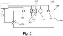
- Figure 2 shows an apparatus 100 for finishing an internal channel 116 of a manufactured component 102.
- the apparatus comprises a continuous flow circuit 104, having a continuous flow line 105 which is configured to direct fluid through the channel 116 of the component 102, receive fluid from the channel 116 and return it in a continuous loop.
- fluid may be directed to flow through a noncontinuous flow line.
- the component 102 is received in the flow line 105 such that the internal channel 116 is fluidically connected to the flow line 105 to receive fluid from an upstream portion of the flow line 105 and discharge fluid back into a downstream portion of the flow line 105.
- the component 102 is manufactured by ALM, and therefore may comprise surface irregularities such as balling melts, stepping effects on the surface of the internal channel 116.
- the component may be made by any suitable manufacturing method.
- the component Figures 3 and 4 described below show examples arrangements for connecting the flow line 105 to the component 102 in more detail.
- the apparatus 100 is configured to finish an internal channel of the component 102 by directing and controlling a fluid flow through the internal channel such that cavitation bubbles are formed by a hydrodynamic effect, in particular due to a drop in hydrostatic pressure below the vapour pressure of the working fluid at a given temperature.
- the cavitation bubbles are thought to implode to generate shock waves which in turn generate micro jets.
- the micro jets are thought to cause micro pits or cracks on the surface of the internal channel 116, and thereby remove loosely bonded particles on the internal surface, or erode or remove balling melts from the internal surface of a component made by ALM.
- the flow circuit 104 comprises a pump 106 which is configured to drive the fluid around the flow circuit 104.
- the pump 106 pumps fluid in a clockwise direction around the flow line 105 loop as shown in Figure 2 and is a variable flow pump so that the flow rate of the fluid in the flow circuit 104 can be varied.
- the pump may be a fixed flow pump and/or may be operated to pump in two directions.
- the flow circuit 104 further comprises an upstream valve 108 and a downstream valve 110.
- the upstream valve 108 is located upstream of the component 102 relative to the flow direction in use
- the downstream valve 110 is located downstream of the component 102 relative to the flow direction in use.
- the upstream valve 108 and the downstream valve 110 can be used to control the pressure of the fluid in the internal channel 116 of the component 102 as will be described below.
- the upstream valve 108 is located between the pump 106 and the component 102, and the downstream valve 110 is located between the component 102 and the pump 106.
- the pump may be located anywhere in the flow circuit 104 to drive fluid through the component 102 when in use.
- the flow circuit 104 also comprises a sensor 114 which is located between the upstream valve 108 and the downstream valve 110 and is configured to monitor acoustic conditions of the fluid flow through the component 102 to monitor cavitation intensity i.e. a parameter relating to the intensity of the eroding and/or abrading effect of cavitation bubbles in the flow.
- the sensor 114 may be, for example, an acoustic emissions (AE) sensor, an acoustic sensor (such as hydrophone or a polyvinylidene fluoride (PVDF) sensor).
- AE acoustic emissions
- PVDF polyvinylidene fluoride
- the apparatus 100 comprises a heater 140 configured to locally heat the component 102 at a heating location on the component, and thereby locally heat fluid at an internal location corresponding to the heating location.
- the heater 140 comprises two heating coils 140 disposed around an outer surface of the component 102 at upstream and downstream heating locations spaced apart along a length of the component corresponding to the direction of flow through the internal channel 116. Increasing the temperature of the fluid is thought to increase the cavitation intensity by increasing the generation of cavitation bubbles by a hydrodynamic effect, and increasing the intensity of the cavitation implosion.
- the apparatus may comprise a heater configured to heat fluid upstream of the component, for example a heater disposed within the fluid upstream of the component or at an internal location within the component, so that the fluid is heated directly by the heater.
- the apparatus 100 further comprises a controller 120 which is connected to the pump 106, the upstream valve 108, the downstream valve 110, the sensor 114 and the heating coil 140.
- the controller 120 is configured to receive data from the sensor 114.
- the controller 120 is configured to control any or all of the pump 106, the upstream valve 108, the downstream valve 108 and the heating coil 140 to maintain the cavitation intensity at a predetermined level based on data received from the sensor 114.
- the controller may be configured to display the sensor data to a user to permit manual control and variation of the pump and/or valves by user input.
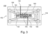
- Figure 3 shows a first example arrangement 150 for receiving the component 102 within the flow circuit 104.
- the component 102 is received in the flow circuit 104 of Figure 2 within a chamber 150.
- the chamber 150 comprises an inlet 152 and an outlet 154 separated along a longitudinal direction and which are fluidically connected to the flow lines 105 of the flow circuit to complete the flow loop of the flow circuit 104 as described above.
- the component 102 is a simple tube or pipe, extending along an axial extent with a constant diameter.
- the component 102 may be any shape and may have any number of complex internal channels for finishing.
- the chamber 150 has a circular cross section in planes normal to the longitudinal direction and defines a convergent-divergent passage for fluid flow.
- the passage comprises a convergent upstream portion 156, a central portion 158 and a divergent downstream portion 160.
- central portion 158 is substantially cylindrical with internal dimensions corresponding to external dimensions of the component 102, and the component 102 is received therein.
- the component may be retained in the central portion by any suitable means, such as by clamping, by a frictional fit, or by virtue of cooperating formations of the central portion 158 and the component 102.
- the central portion 158 in this example is cylindrical, it may be of any shape to accommodate a component which for internal finishing.
- the heating coil 140 of the apparatus has a longitudinal extent corresponding to the longitudinal extent of the component 102 so as to provide substantially uniform heating along the component.
- the upstream portion 156 of the passage further comprises a flow restrictor 162, which is configured to have an opening narrower than the local diameter of the upstream portion and configured to generate cavitation bubbles 164 by a hydrodynamic effect in fluid flowing therethrough.
- the flow restrictor 162 is in the form of an orifice plate.
- the component 102 is received in the chamber 150 and the pump 106 pumps fluid around the flow circuit 104.
- the pump 106, upstream valve 108, downstream valve 110 and heating coil 140 may be controlled by the controller 120 to maintain a predetermined cavitation intensity, or according to predetermined operating parameters (e.g. pump speed, valve setting, heating power).
- the fluid in this example is pure water for an erosion stage of finishing in which the surface of the internal channel is finished to a coarse finish (e.g. relatively high roughness), and further comprises suspended abrasive media 166 for an abrasive stage of finishing in which the surface is finished to a finer finish (e.g. relatively lower roughness).
- the abrasive media may comprise abrasive particles that are present in fluid in a concentration of up to 30% (by weight). The concentration range of up to 30 % (by wt.) of abrasive particles provides for a particularly effective finer finish to the surface of the component.
- the abrasive particles may have a mean particle size of between 10 ⁇ m and 100 ⁇ m.
- the abrasive particles may be formed from any suitable abrasive material such as, for example, silicon carbide, cubic boron nitride, alumina, hematite, quartz, and apatite.
- the fluid may be any fluid with a viscosity of between 0.1 mPa.s and 100mPa.s at 25 degrees Celsius.
- the fluid passes through the orifice plate 162 so that cavitation bubbles 164 form in the fluid.
- the cavitation bubbles 164 flow with fluid along the internal channel of the component 102, until they implode in proximity to the surface, thereby removing loosely bonded particles on the internal surface, or remove balling melts from the internal surface.
- abrasive media 166 may cause additional cavitation bubbles to be generated in a fluid flow (i.e. when compared to a similar flow without abrasive media). Therefore, the intensity of cavitation bubble generation may be increased by the presence of abrasive media 166 in the flow.
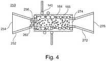
- Figure 4 shows a second example arrangement 250 for receiving the component 102 within the flow circuit 104 of Figure 2 .
- the component 102 is received between an upstream nozzle 252 and a downstream nozzle 272.
- Both nozzles 252, 272 are configured for fluidically connecting to the flow line 105 of Figure 2 .
- the upstream nozzle 252 is configured to connect at its inlet end 254 to the flow line 105 and is connected at its outlet end 256 to the component 102.
- the upstream nozzle 252 has a circular cross section of variable diameter and tapers from the inlet end 254 to the outlet end 256.
- the upstream nozzle 252 has a portion of constant diameter at the outlet end 256.
- the downstream nozzle 272 is configured to connect at its outlet end 276 to the flow line 105 and is connected at its inlet end 274 to the component 102.
- the downstream nozzle 272 has a circular cross section of variable diameter and tapers from the outlet end 276 to the inlet end 274.
- the downstream nozzle 272 has a portion of constant diameter at the inlet end 274.
- the outlet end 256 of the upstream nozzle 252 and the inlet end 274 of the downstream nozzle 272 are sized to fit into the respective ends of the component 102 to fluidically connect the internal channel of the component 102 to the flow line 105.
- the upstream nozzle 252 comprises a flow restrictor 262 which is similar to the flow restrictor 162 described with reference to Figure 3 .
- the flow restrictor 162 causes cavitation bubbles 164 to be formed by a hydrodynamic effect when fluid is driven through it.
- the heating coil 140 is wound around the component 102 at an enhanced treatment region i.e. at a region on the component 102 where it is intended to promote additional local smoothing. It may be desirable to target the cavitation bubbles to erode the internal surface with a higher intensity at the enhanced smoothing region, for example to provide a locally-smoother surface (e.g. for performance), or erode a locally-rougher surface (e.g. where a manufacturing method may generate a region of relatively high local roughness). In use, the heating coil 140 locally increases the temperature of the component 102 and thereby fluid in the internal channel 116, so as to locally increasing the cavitation intensity.
- an enhanced treatment region i.e. at a region on the component 102 where it is intended to promote additional local smoothing. It may be desirable to target the cavitation bubbles to erode the internal surface with a higher intensity at the enhanced smoothing region, for example to provide a locally-smoother surface (e.g. for performance), or erode a locally-rougher surface
- the second example arrangement for receiving a component in the flow circuit according to Figure 4 differs from the first example arrangement described above with respect to Figure 3 in that a heater is provided to locally heat a sub-portion of the component, rather than being distributed along the full extent of the component.
- a heater is provided to locally heat a sub-portion of the component, rather than being distributed along the full extent of the component.
- Such heating arrangements are interchangeable, such that the full-length heater of Figure 3 could be applied to the arrangement of Figure 4 , and vice versa.
- first and second example arrangements 150, 250 each comprise a flow restrictor 162, 262 upstream of the component 102, in some examples, there may be no flow restrictor, and cavitation bubbles may be formed by interaction of the flow with the balling melts in the internal channel and/or the abrasive media in the abrasive stage.
- Figure 5 is a flowchart 300 showing a method of finishing an internal channel 116 of a component 102.
- the method is described with reference to the apparatus 100 of Figures 2 to 4 .
- the component 102 is installed in the flow line 105 of the apparatus 100.
- the component 102 can be received in the apparatus in any manner which allows fluid to flow through the internal channel of the component 102, such as the arrangements 150, 250 described with reference to Figures 3 and 4 .
- the heating coil 140 is heated to heat the component uniformly or at one or more enhanced smoothing regions. This increases the temperature of the fluid, either evenly or locally, thereby increasing the cavitation intensity when the fluid flows. In other examples, there may be no heating coil in the apparatus, and/or block 304 of the method may not be carried out.
- the pump 106 pumps fluid around the flow circuit 104, and into the internal channel 116 of the component 102 in an erosion stage.
- the fluid passes through the flow restrictor 162, 262 which causes generation of cavitation bubbles by a hydrodynamic effect.
- the component 102 has been manufactured by ALM, and therefore the surface of the internal channel 116 may comprise balling melts.
- the balling melts also act as small constrictions in the flow, such that flow over the balling melts generates cavitation bubbles.
- the cavitation bubbles implode in proximity to walls of the internal channel 116. As explained above, implosion of the cavitation bubbles generates shock waves which may generate micro jets. It is thought that the micro jets cause micro pits or cracks on the surface of the internal channel 116, so as to remove loosely bonded particles on the internal surface, or erode/remove the balling melts.
- the cavitation intensity is monitored with the sensors 114.
- the cavitation intensity relates to the amount of cavitation bubbles which are generated and/or to the intensity of implosion of the cavitation bubbles.
- the cavitation intensity is monitored with the sensors 114 at a high sampling rate (e.g. 8 kHz to 180 kHz), and the sensors 114 send the data to the controller 120.
- the sensors 114 include an acoustic sensor configured to generate an acoustic parameter (e.g. amplitude in a predetermined or peak frequency band, peak frequency, energy in a predetermined or peak frequency band) which is a function of the cavitation intensity.
- the cavitation intensity may not be monitored at all, but may be estimated using a formula.
- the controller 120 receives data from the sensors 114 and controls the fluid flow through the internal channel 116 by controlling any or all of the pump 106, upstream valve 108, the downstream valve 110 and the heating coil 140. By controlling the fluid flow in response to the data received from the sensors 114, the controller 120 can control the cavitation intensity in the internal channel 116.
- the sensor 114 may transmit data to a display for a user.
- the controller may respond directly to inputs from the user to control the pump, the valves and the heating coil, or may apply pre-determined settings for each of the respective components
- Each one of blocks 304 to 310 may be performed concurrently or sequentially with each other.
- fluid may be continuously pumped around the flow circuit. Heating, monitoring and control may be conducted whilst the fluid is being pumped around the flow circuit in the erosion stage.
- the cavitation bubbles erode the surface of the internal channel by removing balling melts and loosely bonded particles. Erosion by the cavitation bubbles is thought to leave a relative coarse surface finish (e.g. relatively high surface roughness).
- abrasive media 166 is added to the fluid flow in an abrasive stage.
- the pump 106 continues to pump fluid around the flow circuit 104 according to block 306, the sensors 114 continue to monitor the cavitation intensity according to block 308, and the controller 120 continues to control the cavitation intensity based on data from the sensor 114.
- local heating may also continue in the abrasive stage (block 304)
- the abrasive media 166 abrades the internal channel 116, in the abrasive stage, to a finer finish than that achieved by the cavitation bubbles alone in the erosion stage.
- cavitation bubbles continue to be generated in the abrasive stage, and it is thought that implosion of the cavitation bubbles accelerates the abrasive media to enhance the abrasive effect
- the abrasive media 166 may have surface imperfections which trap gases while travelling at high speeds, resulting in a local pressure drop, and thereby generating more cavitation bubbles to accelerate the abrasive media and enhance the finishing.
- cavitation bubbles may be effective in removing relatively large imperfections in the surface of the internal channel 116, such as loosely bonded particles and balling melts, they may be less effective (at least without abrasive media) in smoothing or removing the bulk material of the component.
- the abrasive media 166 is therefore introduced to abrade the surface, and may smooth it to a finer finish (e.g. a relatively lower roughness) than the cavitation bubbles alone.
- abrasive media 166 is suspended in a low viscosity fluid, the risk of abrasive particle accumulation at narrow portions or complex bends is reduced when compared to methods relying on a higher viscosity fluid.
- the cavitation bubbles remove blockages in the internal channels before the abrasive media is introduced, to further reduce the risk of abrasive particle accumulation at narrow portions.
- a two-stage finishing procedure e.g. erosion then abrasion
- the speed of the finishing process to achieve a target roughness may be reduced, by providing a relatively fast coarse surface finish in the erosion stage to remove excess material, before applying the finer finishing with the abrasive particles to achieve the target roughness.
- the erosion stage and abrasive stage may occur simultaneously, e.g. the abrasive media may always be provided in the fluid flow. This may also speed up the finishing process as it is thought that the cavitation bubbles and abrasive media erode and abrade the surface simultaneously, until the cavitation bubbles no longer effectively erode the internal channel. At this point it is thought that the further finishing results primarily from the abrasive media fine alone, without any significant further erosion from the coarser cavitation bubbles, as the cavitation bubbles may not remove the well bonded material from the surface.
Landscapes
- Engineering & Computer Science (AREA)
- Mechanical Engineering (AREA)
- Environmental & Geological Engineering (AREA)
- Health & Medical Sciences (AREA)
- Life Sciences & Earth Sciences (AREA)
- Hydrology & Water Resources (AREA)
- Public Health (AREA)
- Water Supply & Treatment (AREA)
- Finish Polishing, Edge Sharpening, And Grinding By Specific Grinding Devices (AREA)
- Grinding-Machine Dressing And Accessory Apparatuses (AREA)
Applications Claiming Priority (1)
| Application Number | Priority Date | Filing Date | Title |
|---|---|---|---|
| GBGB1805763.8A GB201805763D0 (en) | 2018-04-06 | 2018-04-06 | A method and apparatus for finishing an internal channel of a component |
Publications (2)
| Publication Number | Publication Date |
|---|---|
| EP3549718A2 true EP3549718A2 (de) | 2019-10-09 |
| EP3549718A3 EP3549718A3 (de) | 2020-03-11 |
Family
ID=62202830
Family Applications (1)
| Application Number | Title | Priority Date | Filing Date |
|---|---|---|---|
| EP19161477.5A Withdrawn EP3549718A3 (de) | 2018-04-06 | 2019-03-08 | Verfahren und vorrichtung zur endbearbeitung eines internen kanals einer komponente |
Country Status (3)
| Country | Link |
|---|---|
| US (1) | US20190308292A1 (de) |
| EP (1) | EP3549718A3 (de) |
| GB (1) | GB201805763D0 (de) |
Families Citing this family (11)
| Publication number | Priority date | Publication date | Assignee | Title |
|---|---|---|---|---|
| US10836012B2 (en) * | 2017-08-31 | 2020-11-17 | The Boeing Company | Method and apparatus for fluid cavitation abrasive surface finishing |
| US11679454B2 (en) | 2017-08-31 | 2023-06-20 | The Boeing Company | Portable cavitation peening method and apparatus |
| US11878392B2 (en) * | 2018-06-01 | 2024-01-23 | Basf Se | Method for the hydro-erosive grinding of components |
| DE102019201656A1 (de) * | 2019-02-08 | 2020-08-13 | MTU Aero Engines AG | Verfahren zum glätten einer oberfläche eines bauteils |
| DE102019120753B4 (de) * | 2019-07-31 | 2022-06-02 | Extrude Hone Gmbh | Fließläppmaschine, Verfahren zum Ermitteln eines Materialabtrags an einem Werkstück und Verfahren zum Bestimmen der Schneidleistung eines Schleifmediums |
| US12269070B2 (en) | 2020-12-16 | 2025-04-08 | The Boeing Company | Flexible cavitation apparatus |
| EP4307908A1 (de) * | 2021-03-19 | 2024-01-24 | Tetra Laval Holdings & Finance S.A. | Verfahren zum entfernen von ablagerungen in einem abschnitt eines lebensmittelverarbeitungssystems |
| US12296431B2 (en) | 2021-12-02 | 2025-05-13 | The Boeing Company | Automated cavitation processing |
| US12485517B2 (en) | 2021-12-02 | 2025-12-02 | The Boeing Company | Automated cavitation processing |
| CN114473880A (zh) * | 2022-01-18 | 2022-05-13 | 浙江大学 | 一种超声波辅助流体空化研磨设备 |
| US12466028B2 (en) | 2022-07-01 | 2025-11-11 | The Boeing Company | Damage tolerant cavitation nozzle |
Family Cites Families (3)
| Publication number | Priority date | Publication date | Assignee | Title |
|---|---|---|---|---|
| US5183513A (en) * | 1991-05-10 | 1993-02-02 | Applied Hydro Dynamics, Inc. | Method of cleaning internal surfaces utilizing cavitating fluid |
| US9200341B1 (en) * | 2014-07-18 | 2015-12-01 | The Boeing Company | Systems and methods of cavitation peening a workpiece |
| CN106392863B (zh) * | 2016-10-20 | 2019-03-26 | 浙江工业大学 | 一种基于结构空化效应的高效流体光整加工方法及装置 |
-
2018
- 2018-04-06 GB GBGB1805763.8A patent/GB201805763D0/en not_active Ceased
-
2019
- 2019-03-06 US US16/293,705 patent/US20190308292A1/en not_active Abandoned
- 2019-03-08 EP EP19161477.5A patent/EP3549718A3/de not_active Withdrawn
Also Published As
| Publication number | Publication date |
|---|---|
| GB201805763D0 (en) | 2018-05-23 |
| US20190308292A1 (en) | 2019-10-10 |
| EP3549718A3 (de) | 2020-03-11 |
Similar Documents
| Publication | Publication Date | Title |
|---|---|---|
| EP3549718A2 (de) | Verfahren und vorrichtung zur endbearbeitung eines internen kanals einer komponente | |
| EP3953103B1 (de) | Verfahren und vorrichtung zur endbearbeitung eines internen kanals einer komponente | |
| EP3213828B1 (de) | System und verfahren zur reinigung von gasturbinenmotorkomponenten | |
| CN102958616B (zh) | 利用脉冲射流为热喷涂层制备气缸孔表面的方法和设备 | |
| CA2701185C (en) | Method and apparatus for prepping a surface using a coating particle entrained in a pulsed waterjet or airjet | |
| KR20100074153A (ko) | 유체/연마제 제트 컷팅 장치 | |
| JP2006508294A (ja) | 原動機或いは作業機械の流入路への液体噴射を制御する方法 | |
| CN111299592B (zh) | 修整通过增材制造制备的部件的表面 | |
| CN102979586A (zh) | 废气涡轮的清洁装置 | |
| US20110081834A1 (en) | Method for working on workpieces with a water jet that contains abrasive and emerges under high pressure from a nozzle, water jet installation useful for executing the method, and application of the method | |
| US20070098912A1 (en) | Method for producing functionally graded coatings using cold gas-dynamic spraying | |
| US6726778B2 (en) | Method for cleaning and renovating pipelines | |
| RU72514U1 (ru) | Осевой многоступенчатый компрессор | |
| JP2002333000A5 (de) | ||
| US11612977B2 (en) | Method for smoothing a surface of a component | |
| JP7574297B2 (ja) | 生産性が高い静音研磨材ブラストノズルのための方法及び設計 | |
| JP7071030B2 (ja) | ターボ機械からの燃料をパージするためのシステムおよび方法 | |
| RU2246391C2 (ru) | Способ абразивно-газовой обработки поверхности и сопловое устройство для его реализации | |
| CA2408579C (en) | Method for cleaning and renovating pipelines | |
| RU2430796C1 (ru) | Способ очистки внутренних поверхностей деталей | |
| RU2201329C1 (ru) | Способ термоабразивной очистки поверхностей изделий и устройство для его осуществления | |
| CN112609053B (zh) | 一种基于射流辅助的超声滚压强化装置及系统 | |
| RU2288788C2 (ru) | Способ очистки внутренней поверхности нефтегазовых труб от асфальтено-смолопарафиновых отложений | |
| RU2338638C2 (ru) | Способ термоабразивной обработки и машина "бобр" для его осуществления | |
| CN109852780A (zh) | 一种表面喷丸强化的混合喷嘴 |
Legal Events
| Date | Code | Title | Description |
|---|---|---|---|
| PUAI | Public reference made under article 153(3) epc to a published international application that has entered the european phase |
Free format text: ORIGINAL CODE: 0009012 |
|
| STAA | Information on the status of an ep patent application or granted ep patent |
Free format text: STATUS: THE APPLICATION HAS BEEN PUBLISHED |
|
| AK | Designated contracting states |
Kind code of ref document: A2 Designated state(s): AL AT BE BG CH CY CZ DE DK EE ES FI FR GB GR HR HU IE IS IT LI LT LU LV MC MK MT NL NO PL PT RO RS SE SI SK SM TR |
|
| AX | Request for extension of the european patent |
Extension state: BA ME |
|
| PUAL | Search report despatched |
Free format text: ORIGINAL CODE: 0009013 |
|
| RAP1 | Party data changed (applicant data changed or rights of an application transferred) |
Owner name: ROLLS-ROYCE PLC |
|
| AK | Designated contracting states |
Kind code of ref document: A3 Designated state(s): AL AT BE BG CH CY CZ DE DK EE ES FI FR GB GR HR HU IE IS IT LI LT LU LV MC MK MT NL NO PL PT RO RS SE SI SK SM TR |
|
| AX | Request for extension of the european patent |
Extension state: BA ME |
|
| RIC1 | Information provided on ipc code assigned before grant |
Ipc: B24B 31/116 20060101AFI20200203BHEP |
|
| STAA | Information on the status of an ep patent application or granted ep patent |
Free format text: STATUS: THE APPLICATION IS DEEMED TO BE WITHDRAWN |
|
| 18D | Application deemed to be withdrawn |
Effective date: 20200912 |