EP3549549B1 - Milling tool of a dental superstructure - Google Patents
Milling tool of a dental superstructure Download PDFInfo
- Publication number
- EP3549549B1 EP3549549B1 EP17778322.2A EP17778322A EP3549549B1 EP 3549549 B1 EP3549549 B1 EP 3549549B1 EP 17778322 A EP17778322 A EP 17778322A EP 3549549 B1 EP3549549 B1 EP 3549549B1
- Authority
- EP
- European Patent Office
- Prior art keywords
- cutting
- useful
- rod
- milling tool
- tool according
- Prior art date
- Legal status (The legal status is an assumption and is not a legal conclusion. Google has not performed a legal analysis and makes no representation as to the accuracy of the status listed.)
- Active
Links
Images

Classifications
-
- F—MECHANICAL ENGINEERING; LIGHTING; HEATING; WEAPONS; BLASTING
- F41—WEAPONS
- F41A—FUNCTIONAL FEATURES OR DETAILS COMMON TO BOTH SMALLARMS AND ORDNANCE, e.g. CANNONS; MOUNTINGS FOR SMALLARMS OR ORDNANCE
- F41A9/00—Feeding or loading of ammunition; Magazines; Guiding means for the extracting of cartridges
- F41A9/53—Charged-condition indicators, i.e. indicating the presence of a cartridge in the cartridge chamber
-
- A—HUMAN NECESSITIES
- A61—MEDICAL OR VETERINARY SCIENCE; HYGIENE
- A61C—DENTISTRY; APPARATUS OR METHODS FOR ORAL OR DENTAL HYGIENE
- A61C13/00—Dental prostheses; Making same
-
- A—HUMAN NECESSITIES
- A61—MEDICAL OR VETERINARY SCIENCE; HYGIENE
- A61C—DENTISTRY; APPARATUS OR METHODS FOR ORAL OR DENTAL HYGIENE
- A61C13/00—Dental prostheses; Making same
- A61C13/225—Fastening prostheses in the mouth
- A61C13/273—Fastening prostheses in the mouth removably secured to residual teeth by using bolts or locks
-
- A—HUMAN NECESSITIES
- A61—MEDICAL OR VETERINARY SCIENCE; HYGIENE
- A61C—DENTISTRY; APPARATUS OR METHODS FOR ORAL OR DENTAL HYGIENE
- A61C3/00—Dental tools or instruments
- A61C3/06—Tooth grinding or polishing discs; Holders therefor
-
- A—HUMAN NECESSITIES
- A61—MEDICAL OR VETERINARY SCIENCE; HYGIENE
- A61C—DENTISTRY; APPARATUS OR METHODS FOR ORAL OR DENTAL HYGIENE
- A61C8/00—Means to be fixed to the jaw-bone for consolidating natural teeth or for fixing dental prostheses thereon; Dental implants; Implanting tools
-
- B—PERFORMING OPERATIONS; TRANSPORTING
- B23—MACHINE TOOLS; METAL-WORKING NOT OTHERWISE PROVIDED FOR
- B23C—MILLING
- B23C5/00—Milling-cutters
- B23C5/02—Milling-cutters characterised by the shape of the cutter
- B23C5/10—Shank-type cutters, i.e. with an integral shaft
- B23C5/1054—T slot cutters
-
- G—PHYSICS
- G01—MEASURING; TESTING
- G01R—MEASURING ELECTRIC VARIABLES; MEASURING MAGNETIC VARIABLES
- G01R27/00—Arrangements for measuring resistance, reactance, impedance, or electric characteristics derived therefrom
- G01R27/02—Measuring real or complex resistance, reactance, impedance, or other two-pole characteristics derived therefrom, e.g. time constant
- G01R27/26—Measuring inductance or capacitance; Measuring quality factor, e.g. by using the resonance method; Measuring loss factor; Measuring dielectric constants ; Measuring impedance or related variables
- G01R27/2605—Measuring capacitance
-
- B—PERFORMING OPERATIONS; TRANSPORTING
- B23—MACHINE TOOLS; METAL-WORKING NOT OTHERWISE PROVIDED FOR
- B23C—MILLING
- B23C2210/00—Details of milling cutters
- B23C2210/20—Number of cutting edges
- B23C2210/201—Number of cutting edges one
-
- B—PERFORMING OPERATIONS; TRANSPORTING
- B23—MACHINE TOOLS; METAL-WORKING NOT OTHERWISE PROVIDED FOR
- B23C—MILLING
- B23C2210/00—Details of milling cutters
- B23C2210/20—Number of cutting edges
- B23C2210/202—Number of cutting edges three
-
- B—PERFORMING OPERATIONS; TRANSPORTING
- B23—MACHINE TOOLS; METAL-WORKING NOT OTHERWISE PROVIDED FOR
- B23C—MILLING
- B23C2210/00—Details of milling cutters
- B23C2210/24—Overall form of the milling cutter
- B23C2210/247—Stepped milling cutters
- B23C2210/248—Stepped milling cutters with enlarged cutting heads
-
- B—PERFORMING OPERATIONS; TRANSPORTING
- B23—MACHINE TOOLS; METAL-WORKING NOT OTHERWISE PROVIDED FOR
- B23C—MILLING
- B23C2265/00—Details of general geometric configurations
- B23C2265/08—Conical
Definitions
- the present invention consists of a milling tool of a dental structure, used for milling the seat of the screw and the inner diameter of the straight channel of bolted angled dental structures with a direct connection to a dental implant.
- the present invention is of particular application in the dental sector, and more specifically in the sector of dental implants.
- the techniques used so far for machining the channel and the seat of the screw of the structures with direct connection to angled implants consist of introducing a milling cutter from the end of the angled channel to the seat of the screw, as for example in Spanish patent ES2345636T3 .
- This embodiment enables continuity of the channel to the seat, enabling introduction of the screw from outside the angled channel.
- the orifice of the entrance channel is oversized since the angled channel and the inner seat of the screw are machined with the same tool, limiting the possibility of carrying out seats of the screws with different angles. Oversizing of the channel has adverse effects on both the resulting aesthetics and the structural behavior of the structure or superstructure, also reducing its use in the production of more unfavorable situations.
- the present application complements the invention of Spanish patent application 201631582 relating to a method for manufacturing angled dental structures or superstructures, comprising the making of two holes in the superstructure forming two straight channels with a direction that does not coincide, in which a first channel has the direction of the insertion axis and a second channel has the entrance of the screw or angled channel towards an aesthetically pleasing position. Both channels converge in the interior of the structure or superstructure.
- Prior art document US8464768B2 describes a milling tool with a support area for a milling machine and a useful cutting area with a cutting element with different cutting surfaces.
- the present invention solves the lack of tools with special shapes that enable carrying out the milling of the seat of the screw and the inner diameter of the straight channel of angled dental structures or superstructures with direct-to-implant connection.
- the object of the invention is therefore a milling tool of a dental structure or superstructure according to claim 1.
- the invention relates to a milling tool of a dental superstructure, used for the inner milling of the seat of a screw and of a straight channel in angled dental superstructures for screwing by means of a direct connection to a dental implant, comprising:
- the tool may have several tabs, preferably between 2 and 5 cutting tabs.
- Each of said tabs in addition to the useful lower cutting surface, may have a useful upper cutting surface that is perpendicular to the longitudinal axis of the rod and/or a useful lateral cutting surface, which is parallel to the longitudinal axis of the rod.
- the joining edges between the useful cutting surfaces are sharp or rounded edges.
- the dimensions or distances between the different components of the tool are:
- the rod may have a longitudinal cut along the length thereof, reducing its cross-section in order to facilitate access of the tool to the interior of the channel of the dental superstructure.
- Preferably said rod is cylindrical prior to the execution of the cut, said cut being perpendicular to the plane formed between the generatrix of the rod and the base thereof.
- the tool object of the invention can be manufactured in one or several materials, which are preferably chosen from among high-speed steel (HSS) and/or non-ferrous alloys of carbide and/or hard metal and/or ceramic and/or cemented carbide and/or sintered carbide and/or coated carbide, without limitation to other materials used in cutting tools.
- HSS high-speed steel
- some of the elements of the tool may comprise a treatment and/or a surface finish.
- the present invention consists of a precision milling tool (15) intended for prosthetic laboratories and dental milling centers. It is specially designed for milling the seat of a screw (13) and of the inner area (12) of the straight channel (14) of the angled dental structures or superstructures (11) to be screwed by means of direct connection to an implant.
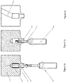
- the present invention relates to a tool (15) that enables carrying out a method for manufacturing angled dental structures or superstructures (11), according to Figures 1a to 1c , and which enables precision machining of the seat of a screw (13) inside the channel of the superstructure, with a straight or conical shape, and without limitation of angles, whether positive of negative, and in turn minimizing the diameter of the entrance hole of the angled channel (19).
- two holes are made in the superstructure (11) forming two straight channels with a non-coinciding direction, in which a first channel has the direction of the insertion axis (14) and a second channel has the entrance of the screw or the angled channel (19) towards an aesthetically pleasing position.
- the first channel consists of two different diameters, a first diameter (14) carried out by means of a first bore or milling cutter and which will exclusively enable passing the screw thread, and a second diameter (12), larger than the previous one, enabling the passage of the screw head through the angled or inclined channel (19) to the surface of the seat (13) where the screw head abuts, limiting its advance along the channel.
- the tool (15) object of the present invention is introduced inside the first channel.
- the diameter (14) of the first channel of the structure or superstructure (11) will depend on the type of connection (16) of said superstructure (11) to the implant.
- the milling tool (15) object of the invention is integrally designed in a single piece without insertable cutting inserts.
- the tool (15) has two areas with different functional nature, a support area (18) and a useful cutting area (17).
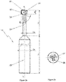
- the useful cutting area (17) of the tool (15) is formed by a cutting element (26) located at the end of the tool (15) and a cylindrical rod (24) that links the cutting element (26) with the support area (25) of the tool (15).
- the length of the useful cutting area (26) Lc varies preferably between 4 and 10 mm.
- the diameter of the rod ⁇ v varies between 0.40 and 1.2 mm depending on the compatibility of the implant being used.
- the cutting element (26) may comprise between one and five cutting tabs (28), preferably three, as shown in Figures 2a and 2b .
- Each cutting tab (28) in turn comprises between one and three useful cutting surfaces (21, 22, 23), which are those in contact with the surface to be milled (12, 13, 14) of the inner channel.
- the cutting tab (28) has three useful cutting surfaces that are the upper surface (21), the lateral surface (22) and the lower surface (23) depending on the position thereof, although the essential useful cutting surface is the lower cutting surface (23).
- This useful lower cutting surface has an angle ⁇ with the longitudinal axis x of the rod (24), or with the useful lateral cutting surface (22), between 15 and 175°, and being able to mill both positive and negative seats of screws, that is, that the angle of the seat of the screw may be upward or downward, i.e. like a V or an inverted V.
- the maximum distance d 1 between the useful upper cutting surface (21) and the useful lower cutting surface (23) is between 0.5 and 4 mm.
- the diameter of the circumscribed circle (27) to the polygon formed by the ends of the tabs varies between 1.3 and 2.1 mm.
- the useful cutting surfaces (21, 22, 23) may be flat or curved surfaces, and the joining edges between the surfaces can be machined, for example, with sharp or rounded edges, depending on the desired finish.
- the support area (25) of the tool (15) enables securing said milling tool (15) to the milling machine by means of a head or a tool holder support.
- the cylindrical end of the support area (25) of the tool (15) enables adjusting it to the head of the milling machine and has a diameter ⁇ s greater than that of the rod ⁇ v.
- the length Ls and diameter ⁇ s of the support area (25) are variable depending on the tool holder head of the milling machine used, the most frequently used diameters being 2, 3, 4, and 6 mm, without limitation to other dimensions that can be used.
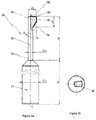
- the tool (30) comprises only one cutting element (31) with a single cutting tab (37), one rod (32) and one support area (34) of the tool (30).
- the cutting tab comprises three useful cutting surfaces (36) although it could incorporate only one, the lower surface, or two, the lower surface and the lateral surface, or the lower surface and the upper surface.
- the construction of this cutting tab (3) is like that of the cutting tabs of the previous example.
- the joining edges (35) are preferably rounded, although they may not be so.
- the lower useful cutting surface is preferably inclined at an angle ⁇ to the longitudinal axis x of the rod (32), or to the useful lateral cutting surface, between 15 and 175°.
- the rod (32) has a longitudinal cut (33) along the rod (32) thus reducing the cross-section of said rod (32) and facilitating access to the interior of the channel of the dental structure or superstructure (11).
- the rod (32) has a circular cross-section whereby in carrying out the cut (33) it no longer has said circular cross-section, said longitudinal cut (33) being perpendicular to the plane formed between the generatrix of the rod (32) and the base thereof.
- this longitudinal cut (33) enables the tool (30) to safely access through the straight channel (14) of the dental structure or superstructure (11), the diameter of which depends on the connection (16) and thread of the compatibility of the implant.
- the maximum distance d 2 between the useful lateral cutting surface and the longitudinal axis x of the rod (32), or the cut if any, varies between 1 and 2.1 mm.
- the maximum distance d 1 between the useful upper cutting surface (21) and the useful lower cutting surface (23) is between 0.5 and 4 mm.
- the support area (34) of the tool (30) enables fastening said milling tool (30) to the milling machine by means of a head or tool holder support.
- the cylindrical end of the support area (34) of the tool (30) enables adjusting it to the head of the milling machine, and it has a diameter ⁇ s greater than the rod ⁇ v.
- the length Ls and diameter ⁇ s of the support area (34) are variable depending on the tool holder head of the milling machine used, the most frequently used diameters being 2, 3, 4, and 6 mm, without limitation to other dimensions that can be used.
- the tool (15, 30) object of the present invention is manufactured from the same material, which may preferably be high-speed steel (HSS), non-ferrous alloys of carbide, hard metal, ceramic, cemented carbide, sintered carbide or coated carbide, without limitation to other materials used in cutting tools.
- HSS high-speed steel
- the tool (15, 30) may or may not have surface treatment and/or surface finish, each area of the tool being able to have a different finish or surface treatment, including lack of treatment.
- the present invention incorporates those treatments or surface finishes intended to modify the behavior of the tool against temperature, wear, hardness, toughness and/or resilience, without limitation to other treatments or surface finishes.
- the useful cutting surfaces (21, 22, 23, 36) of the tool may or may not have a sharp edge depending on the material used in the manufacture thereof.
- the tool (15, 30) object of the invention enables machining biocompatible materials used in dentistry: metals such as titanium alloys and chromium-cobalt alloys, plastics such as PEEK and POM, and ceramics such as zirconium ceramics (zirconia) among other materials.
Landscapes
- Health & Medical Sciences (AREA)
- Animal Behavior & Ethology (AREA)
- Public Health (AREA)
- Veterinary Medicine (AREA)
- Oral & Maxillofacial Surgery (AREA)
- Dentistry (AREA)
- Epidemiology (AREA)
- Engineering & Computer Science (AREA)
- Life Sciences & Earth Sciences (AREA)
- General Health & Medical Sciences (AREA)
- General Engineering & Computer Science (AREA)
- Mechanical Engineering (AREA)
- Orthopedic Medicine & Surgery (AREA)
- Physics & Mathematics (AREA)
- General Physics & Mathematics (AREA)
- Dental Tools And Instruments Or Auxiliary Dental Instruments (AREA)
- Dental Prosthetics (AREA)
Priority Applications (1)
| Application Number | Priority Date | Filing Date | Title |
|---|---|---|---|
| PL17778322T PL3549549T3 (pl) | 2017-01-16 | 2017-05-31 | Narzędzie frezujące do nadbudowy stomatologicznej |
Applications Claiming Priority (2)
| Application Number | Priority Date | Filing Date | Title |
|---|---|---|---|
| ES201730038U ES1175859Y (es) | 2017-01-16 | 2017-01-16 | Herramienta de fresado de una estructura dental |
| PCT/ES2017/070384 WO2018130730A1 (es) | 2017-01-16 | 2017-05-31 | Herramienta de fresado de una superestructura dental |
Publications (2)
| Publication Number | Publication Date |
|---|---|
| EP3549549A1 EP3549549A1 (en) | 2019-10-09 |
| EP3549549B1 true EP3549549B1 (en) | 2020-07-01 |
Family
ID=57956553
Family Applications (1)
| Application Number | Title | Priority Date | Filing Date |
|---|---|---|---|
| EP17778322.2A Active EP3549549B1 (en) | 2017-01-16 | 2017-05-31 | Milling tool of a dental superstructure |
Country Status (4)
| Country | Link |
|---|---|
| EP (1) | EP3549549B1 (pl) |
| ES (2) | ES1175859Y (pl) |
| PL (1) | PL3549549T3 (pl) |
| WO (1) | WO2018130730A1 (pl) |
Families Citing this family (4)
| Publication number | Priority date | Publication date | Assignee | Title |
|---|---|---|---|---|
| ES1225597Y (es) * | 2019-02-05 | 2019-05-20 | Paragon Tools Sl | Herramienta de fresado para el asentamiento de un tornillo en una estructura dental |
| KR102484720B1 (ko) * | 2022-09-01 | 2023-01-03 | 허채헌 | 임플란트용 밀링 버 |
| CN117102598A (zh) * | 2023-09-12 | 2023-11-24 | 宁波兆盈医疗器械有限公司 | 内冷单牙螺纹铣刀及其实施方法 |
| KR102882717B1 (ko) * | 2025-03-14 | 2025-11-12 | (주)신성금속 | 덴탈 가공용 초정밀 엔드밀 |
Family Cites Families (5)
| Publication number | Priority date | Publication date | Assignee | Title |
|---|---|---|---|---|
| DE1139348B (de) * | 1958-04-08 | 1962-11-08 | Hans Nagel | Fraesverfahren und Nutenfraeser zur Herstellung von Profilnuten, insbesondere T- oder L-Nuten |
| US5704736A (en) * | 1995-06-08 | 1998-01-06 | Giannetti; Enrico R. | Dove-tail end mill having replaceable cutter inserts |
| US20040156689A1 (en) * | 2003-02-07 | 2004-08-12 | Shen Shui Liang | Drill bit |
| ATE466540T2 (de) | 2006-08-25 | 2010-05-15 | Biomain Ab | Dentale superstruktur und verfahren zu ihrer herstellung |
| CN107614170B (zh) * | 2015-06-29 | 2019-06-18 | 兼房株式会社 | 基于立铣刀的凹坑加工方法以及立铣刀 |
-
2017
- 2017-01-16 ES ES201730038U patent/ES1175859Y/es active Active
- 2017-05-31 EP EP17778322.2A patent/EP3549549B1/en active Active
- 2017-05-31 ES ES17778322T patent/ES2819998T3/es active Active
- 2017-05-31 WO PCT/ES2017/070384 patent/WO2018130730A1/es not_active Ceased
- 2017-05-31 PL PL17778322T patent/PL3549549T3/pl unknown
Non-Patent Citations (1)
| Title |
|---|
| None * |
Also Published As
| Publication number | Publication date |
|---|---|
| ES1175859U (es) | 2017-02-09 |
| EP3549549A1 (en) | 2019-10-09 |
| ES1175859Y (es) | 2017-05-03 |
| WO2018130730A1 (es) | 2018-07-19 |
| ES2819998T3 (es) | 2021-04-19 |
| PL3549549T3 (pl) | 2021-02-08 |
Similar Documents
| Publication | Publication Date | Title |
|---|---|---|
| EP3549549A1 (en) | Milling tool of a dental superstructure | |
| RU2338630C2 (ru) | Режущий инструмент и способ изготовления его державки | |
| US20250009486A1 (en) | Dental abutment blank, method of manufacturing a dental abutment blank and method of manufacturing a dental prosthesis from such a blank | |
| Aurich et al. | Manufacture and application of ultra-small micro end mills | |
| RU2409454C2 (ru) | Концевая фреза для орбитального фрезерования | |
| EP3378434B1 (en) | Method for the production of a dental structure | |
| EP3023078B1 (en) | Interface element for dental prostheses | |
| KR101982823B1 (ko) | 지대주 부착물용 밀링 블랭크 | |
| JP7049263B2 (ja) | 金属切削のための面溝入れ工具体 | |
| CN104785840A (zh) | 具有带悬臂构件的刀片凹座的切削工具 | |
| US20200406362A1 (en) | Turning method for a cnc-lathe | |
| Grechishnikov et al. | Lathe turning of complex-shaped parts providing desired surface microrelief. | |
| US11020832B2 (en) | Clamping system for abutment blank | |
| JP5438604B2 (ja) | 変化するねじ山断面形状を備えているねじ込み体を製造する方法 | |
| CN107921556A (zh) | 切削刀具、刀具本体和用于生产刀具本体的方法 | |
| RU2237549C1 (ru) | Сменная режущая пластина | |
| Nastasenko | Gear cutting by multiple-thread worm milling cutter as an alternative to gear-broaching |
Legal Events
| Date | Code | Title | Description |
|---|---|---|---|
| STAA | Information on the status of an ep patent application or granted ep patent |
Free format text: STATUS: UNKNOWN |
|
| STAA | Information on the status of an ep patent application or granted ep patent |
Free format text: STATUS: THE INTERNATIONAL PUBLICATION HAS BEEN MADE |
|
| PUAI | Public reference made under article 153(3) epc to a published international application that has entered the european phase |
Free format text: ORIGINAL CODE: 0009012 |
|
| STAA | Information on the status of an ep patent application or granted ep patent |
Free format text: STATUS: REQUEST FOR EXAMINATION WAS MADE |
|
| 17P | Request for examination filed |
Effective date: 20190701 |
|
| AK | Designated contracting states |
Kind code of ref document: A1 Designated state(s): AL AT BE BG CH CY CZ DE DK EE ES FI FR GB GR HR HU IE IS IT LI LT LU LV MC MK MT NL NO PL PT RO RS SE SI SK SM TR |
|
| AX | Request for extension of the european patent |
Extension state: BA ME |
|
| GRAP | Despatch of communication of intention to grant a patent |
Free format text: ORIGINAL CODE: EPIDOSNIGR1 |
|
| STAA | Information on the status of an ep patent application or granted ep patent |
Free format text: STATUS: GRANT OF PATENT IS INTENDED |
|
| DAV | Request for validation of the european patent (deleted) | ||
| DAX | Request for extension of the european patent (deleted) | ||
| INTG | Intention to grant announced |
Effective date: 20200407 |
|
| GRAS | Grant fee paid |
Free format text: ORIGINAL CODE: EPIDOSNIGR3 |
|
| GRAA | (expected) grant |
Free format text: ORIGINAL CODE: 0009210 |
|
| STAA | Information on the status of an ep patent application or granted ep patent |
Free format text: STATUS: THE PATENT HAS BEEN GRANTED |
|
| AK | Designated contracting states |
Kind code of ref document: B1 Designated state(s): AL AT BE BG CH CY CZ DE DK EE ES FI FR GB GR HR HU IE IS IT LI LT LU LV MC MK MT NL NO PL PT RO RS SE SI SK SM TR |
|
| REG | Reference to a national code |
Ref country code: CH Ref legal event code: EP Ref country code: AT Ref legal event code: REF Ref document number: 1285422 Country of ref document: AT Kind code of ref document: T Effective date: 20200715 |
|
| REG | Reference to a national code |
Ref country code: IE Ref legal event code: FG4D |
|
| REG | Reference to a national code |
Ref country code: DE Ref legal event code: R096 Ref document number: 602017019127 Country of ref document: DE |
|
| REG | Reference to a national code |
Ref country code: CH Ref legal event code: NV Representative=s name: VALIPAT S.A. C/O BOVARD SA NEUCHATEL, CH |
|
| REG | Reference to a national code |
Ref country code: SE Ref legal event code: TRGR |
|
| REG | Reference to a national code |
Ref country code: LT Ref legal event code: MG4D |
|
| PG25 | Lapsed in a contracting state [announced via postgrant information from national office to epo] |
Ref country code: BG Free format text: LAPSE BECAUSE OF FAILURE TO SUBMIT A TRANSLATION OF THE DESCRIPTION OR TO PAY THE FEE WITHIN THE PRESCRIBED TIME-LIMIT Effective date: 20201001 |
|
| REG | Reference to a national code |
Ref country code: NL Ref legal event code: MP Effective date: 20200701 |
|
| REG | Reference to a national code |
Ref country code: AT Ref legal event code: MK05 Ref document number: 1285422 Country of ref document: AT Kind code of ref document: T Effective date: 20200701 |
|
| REG | Reference to a national code |
Ref country code: DE Ref legal event code: R082 Ref document number: 602017019127 Country of ref document: DE Representative=s name: SCHOPPE, ZIMMERMANN, STOECKELER, ZINKLER, SCHE, DE Ref country code: DE Ref legal event code: R081 Ref document number: 602017019127 Country of ref document: DE Owner name: TALLADIUM ESPANA, S.L., ES Free format text: FORMER OWNER: XAM-MAR MANGRANE, ESTEBAN, LLEIDA, ES |
|
| PG25 | Lapsed in a contracting state [announced via postgrant information from national office to epo] |
Ref country code: FI Free format text: LAPSE BECAUSE OF FAILURE TO SUBMIT A TRANSLATION OF THE DESCRIPTION OR TO PAY THE FEE WITHIN THE PRESCRIBED TIME-LIMIT Effective date: 20200701 Ref country code: HR Free format text: LAPSE BECAUSE OF FAILURE TO SUBMIT A TRANSLATION OF THE DESCRIPTION OR TO PAY THE FEE WITHIN THE PRESCRIBED TIME-LIMIT Effective date: 20200701 Ref country code: NO Free format text: LAPSE BECAUSE OF FAILURE TO SUBMIT A TRANSLATION OF THE DESCRIPTION OR TO PAY THE FEE WITHIN THE PRESCRIBED TIME-LIMIT Effective date: 20201001 Ref country code: PT Free format text: LAPSE BECAUSE OF FAILURE TO SUBMIT A TRANSLATION OF THE DESCRIPTION OR TO PAY THE FEE WITHIN THE PRESCRIBED TIME-LIMIT Effective date: 20201102 Ref country code: CZ Free format text: LAPSE BECAUSE OF FAILURE TO SUBMIT A TRANSLATION OF THE DESCRIPTION OR TO PAY THE FEE WITHIN THE PRESCRIBED TIME-LIMIT Effective date: 20200701 Ref country code: AT Free format text: LAPSE BECAUSE OF FAILURE TO SUBMIT A TRANSLATION OF THE DESCRIPTION OR TO PAY THE FEE WITHIN THE PRESCRIBED TIME-LIMIT Effective date: 20200701 Ref country code: LT Free format text: LAPSE BECAUSE OF FAILURE TO SUBMIT A TRANSLATION OF THE DESCRIPTION OR TO PAY THE FEE WITHIN THE PRESCRIBED TIME-LIMIT Effective date: 20200701 |
|
| PG25 | Lapsed in a contracting state [announced via postgrant information from national office to epo] |
Ref country code: LV Free format text: LAPSE BECAUSE OF FAILURE TO SUBMIT A TRANSLATION OF THE DESCRIPTION OR TO PAY THE FEE WITHIN THE PRESCRIBED TIME-LIMIT Effective date: 20200701 Ref country code: RS Free format text: LAPSE BECAUSE OF FAILURE TO SUBMIT A TRANSLATION OF THE DESCRIPTION OR TO PAY THE FEE WITHIN THE PRESCRIBED TIME-LIMIT Effective date: 20200701 Ref country code: IS Free format text: LAPSE BECAUSE OF FAILURE TO SUBMIT A TRANSLATION OF THE DESCRIPTION OR TO PAY THE FEE WITHIN THE PRESCRIBED TIME-LIMIT Effective date: 20201101 |
|
| REG | Reference to a national code |
Ref country code: ES Ref legal event code: PC2A Owner name: TALLADIUM ESPANA, S.L. Effective date: 20210311 |
|
| PG25 | Lapsed in a contracting state [announced via postgrant information from national office to epo] |
Ref country code: NL Free format text: LAPSE BECAUSE OF FAILURE TO SUBMIT A TRANSLATION OF THE DESCRIPTION OR TO PAY THE FEE WITHIN THE PRESCRIBED TIME-LIMIT Effective date: 20200701 |
|
| REG | Reference to a national code |
Ref country code: DE Ref legal event code: R097 Ref document number: 602017019127 Country of ref document: DE |
|
| REG | Reference to a national code |
Ref country code: ES Ref legal event code: FG2A Ref document number: 2819998 Country of ref document: ES Kind code of ref document: T3 Effective date: 20210419 |
|
| PG25 | Lapsed in a contracting state [announced via postgrant information from national office to epo] |
Ref country code: DK Free format text: LAPSE BECAUSE OF FAILURE TO SUBMIT A TRANSLATION OF THE DESCRIPTION OR TO PAY THE FEE WITHIN THE PRESCRIBED TIME-LIMIT Effective date: 20200701 Ref country code: RO Free format text: LAPSE BECAUSE OF FAILURE TO SUBMIT A TRANSLATION OF THE DESCRIPTION OR TO PAY THE FEE WITHIN THE PRESCRIBED TIME-LIMIT Effective date: 20200701 Ref country code: EE Free format text: LAPSE BECAUSE OF FAILURE TO SUBMIT A TRANSLATION OF THE DESCRIPTION OR TO PAY THE FEE WITHIN THE PRESCRIBED TIME-LIMIT Effective date: 20200701 Ref country code: SM Free format text: LAPSE BECAUSE OF FAILURE TO SUBMIT A TRANSLATION OF THE DESCRIPTION OR TO PAY THE FEE WITHIN THE PRESCRIBED TIME-LIMIT Effective date: 20200701 |
|
| PLBE | No opposition filed within time limit |
Free format text: ORIGINAL CODE: 0009261 |
|
| STAA | Information on the status of an ep patent application or granted ep patent |
Free format text: STATUS: NO OPPOSITION FILED WITHIN TIME LIMIT |
|
| PG25 | Lapsed in a contracting state [announced via postgrant information from national office to epo] |
Ref country code: AL Free format text: LAPSE BECAUSE OF FAILURE TO SUBMIT A TRANSLATION OF THE DESCRIPTION OR TO PAY THE FEE WITHIN THE PRESCRIBED TIME-LIMIT Effective date: 20200701 |
|
| 26N | No opposition filed |
Effective date: 20210406 |
|
| PG25 | Lapsed in a contracting state [announced via postgrant information from national office to epo] |
Ref country code: SK Free format text: LAPSE BECAUSE OF FAILURE TO SUBMIT A TRANSLATION OF THE DESCRIPTION OR TO PAY THE FEE WITHIN THE PRESCRIBED TIME-LIMIT Effective date: 20200701 |
|
| PG25 | Lapsed in a contracting state [announced via postgrant information from national office to epo] |
Ref country code: SI Free format text: LAPSE BECAUSE OF FAILURE TO SUBMIT A TRANSLATION OF THE DESCRIPTION OR TO PAY THE FEE WITHIN THE PRESCRIBED TIME-LIMIT Effective date: 20200701 |
|
| REG | Reference to a national code |
Ref country code: GB Ref legal event code: 732E Free format text: REGISTERED BETWEEN 20211111 AND 20211117 |
|
| PG25 | Lapsed in a contracting state [announced via postgrant information from national office to epo] |
Ref country code: LU Free format text: LAPSE BECAUSE OF NON-PAYMENT OF DUE FEES Effective date: 20210531 Ref country code: MC Free format text: LAPSE BECAUSE OF FAILURE TO SUBMIT A TRANSLATION OF THE DESCRIPTION OR TO PAY THE FEE WITHIN THE PRESCRIBED TIME-LIMIT Effective date: 20200701 |
|
| REG | Reference to a national code |
Ref country code: BE Ref legal event code: PD Owner name: TALLADIUM ESPANA, S.L.; ES Free format text: DETAILS ASSIGNMENT: CHANGE OF OWNER(S), ASSIGNMENT; FORMER OWNER NAME: XAM-MAR MANGRANE, ESTEBAN Effective date: 20220211 |
|
| PG25 | Lapsed in a contracting state [announced via postgrant information from national office to epo] |
Ref country code: IE Free format text: LAPSE BECAUSE OF NON-PAYMENT OF DUE FEES Effective date: 20210531 |
|
| P01 | Opt-out of the competence of the unified patent court (upc) registered |
Effective date: 20230522 |
|
| PG25 | Lapsed in a contracting state [announced via postgrant information from national office to epo] |
Ref country code: CY Free format text: LAPSE BECAUSE OF FAILURE TO SUBMIT A TRANSLATION OF THE DESCRIPTION OR TO PAY THE FEE WITHIN THE PRESCRIBED TIME-LIMIT Effective date: 20200701 |
|
| PG25 | Lapsed in a contracting state [announced via postgrant information from national office to epo] |
Ref country code: HU Free format text: LAPSE BECAUSE OF FAILURE TO SUBMIT A TRANSLATION OF THE DESCRIPTION OR TO PAY THE FEE WITHIN THE PRESCRIBED TIME-LIMIT; INVALID AB INITIO Effective date: 20170531 Ref country code: GR Free format text: LAPSE BECAUSE OF FAILURE TO SUBMIT A TRANSLATION OF THE DESCRIPTION OR TO PAY THE FEE WITHIN THE PRESCRIBED TIME-LIMIT Effective date: 20200701 |
|
| PG25 | Lapsed in a contracting state [announced via postgrant information from national office to epo] |
Ref country code: MK Free format text: LAPSE BECAUSE OF FAILURE TO SUBMIT A TRANSLATION OF THE DESCRIPTION OR TO PAY THE FEE WITHIN THE PRESCRIBED TIME-LIMIT Effective date: 20200701 |
|
| PG25 | Lapsed in a contracting state [announced via postgrant information from national office to epo] |
Ref country code: MT Free format text: LAPSE BECAUSE OF FAILURE TO SUBMIT A TRANSLATION OF THE DESCRIPTION OR TO PAY THE FEE WITHIN THE PRESCRIBED TIME-LIMIT Effective date: 20200701 |
|
| PGFP | Annual fee paid to national office [announced via postgrant information from national office to epo] |
Ref country code: PL Payment date: 20250505 Year of fee payment: 9 Ref country code: DE Payment date: 20250529 Year of fee payment: 9 |
|
| PGFP | Annual fee paid to national office [announced via postgrant information from national office to epo] |
Ref country code: ES Payment date: 20250602 Year of fee payment: 9 Ref country code: GB Payment date: 20250527 Year of fee payment: 9 |
|
| PGFP | Annual fee paid to national office [announced via postgrant information from national office to epo] |
Ref country code: BE Payment date: 20250527 Year of fee payment: 9 Ref country code: IT Payment date: 20250521 Year of fee payment: 9 |
|
| PGFP | Annual fee paid to national office [announced via postgrant information from national office to epo] |
Ref country code: FR Payment date: 20250526 Year of fee payment: 9 |
|
| PGFP | Annual fee paid to national office [announced via postgrant information from national office to epo] |
Ref country code: CH Payment date: 20250601 Year of fee payment: 9 |
|
| PGFP | Annual fee paid to national office [announced via postgrant information from national office to epo] |
Ref country code: SE Payment date: 20250527 Year of fee payment: 9 |
|
| PG25 | Lapsed in a contracting state [announced via postgrant information from national office to epo] |
Ref country code: TR Free format text: LAPSE BECAUSE OF FAILURE TO SUBMIT A TRANSLATION OF THE DESCRIPTION OR TO PAY THE FEE WITHIN THE PRESCRIBED TIME-LIMIT Effective date: 20200701 |
|
| REG | Reference to a national code |
Ref country code: CH Ref legal event code: R18 Free format text: ST27 STATUS EVENT CODE: U-0-0-R10-R18 (AS PROVIDED BY THE NATIONAL OFFICE) Effective date: 20260209 |
|
| REG | Reference to a national code |
Ref country code: CH Ref legal event code: R18 Free format text: ST27 STATUS EVENT CODE: U-0-0-R10-R18 (AS PROVIDED BY THE NATIONAL OFFICE) Effective date: 20260320 |