EP3549410B1 - Cyclotron rf resonator with asymmetrical tuning - Google Patents
Cyclotron rf resonator with asymmetrical tuning Download PDFInfo
- Publication number
- EP3549410B1 EP3549410B1 EP18700059.1A EP18700059A EP3549410B1 EP 3549410 B1 EP3549410 B1 EP 3549410B1 EP 18700059 A EP18700059 A EP 18700059A EP 3549410 B1 EP3549410 B1 EP 3549410B1
- Authority
- EP
- European Patent Office
- Prior art keywords
- cyclotron
- tuner
- resonator
- radiofrequency
- fixed short
- Prior art date
- Legal status (The legal status is an assumption and is not a legal conclusion. Google has not performed a legal analysis and makes no representation as to the accuracy of the status listed.)
- Active
Links
Images



Classifications
-
- H—ELECTRICITY
- H05—ELECTRIC TECHNIQUES NOT OTHERWISE PROVIDED FOR
- H05H—PLASMA TECHNIQUE; PRODUCTION OF ACCELERATED ELECTRICALLY-CHARGED PARTICLES OR OF NEUTRONS; PRODUCTION OR ACCELERATION OF NEUTRAL MOLECULAR OR ATOMIC BEAMS
- H05H7/00—Details of devices of the types covered by groups H05H9/00, H05H11/00, H05H13/00
- H05H7/02—Circuits or systems for supplying or feeding radio-frequency energy
-
- H—ELECTRICITY
- H05—ELECTRIC TECHNIQUES NOT OTHERWISE PROVIDED FOR
- H05H—PLASMA TECHNIQUE; PRODUCTION OF ACCELERATED ELECTRICALLY-CHARGED PARTICLES OR OF NEUTRONS; PRODUCTION OR ACCELERATION OF NEUTRAL MOLECULAR OR ATOMIC BEAMS
- H05H13/00—Magnetic resonance accelerators; Cyclotrons
- H05H13/005—Cyclotrons
-
- A—HUMAN NECESSITIES
- A61—MEDICAL OR VETERINARY SCIENCE; HYGIENE
- A61N—ELECTROTHERAPY; MAGNETOTHERAPY; RADIATION THERAPY; ULTRASOUND THERAPY
- A61N5/00—Radiation therapy
- A61N5/10—X-ray therapy; Gamma-ray therapy; Particle-irradiation therapy
- A61N5/1077—Beam delivery systems
-
- H—ELECTRICITY
- H05—ELECTRIC TECHNIQUES NOT OTHERWISE PROVIDED FOR
- H05H—PLASMA TECHNIQUE; PRODUCTION OF ACCELERATED ELECTRICALLY-CHARGED PARTICLES OR OF NEUTRONS; PRODUCTION OR ACCELERATION OF NEUTRAL MOLECULAR OR ATOMIC BEAMS
- H05H7/00—Details of devices of the types covered by groups H05H9/00, H05H11/00, H05H13/00
- H05H7/08—Arrangements for injecting particles into orbits
-
- H—ELECTRICITY
- H05—ELECTRIC TECHNIQUES NOT OTHERWISE PROVIDED FOR
- H05H—PLASMA TECHNIQUE; PRODUCTION OF ACCELERATED ELECTRICALLY-CHARGED PARTICLES OR OF NEUTRONS; PRODUCTION OR ACCELERATION OF NEUTRAL MOLECULAR OR ATOMIC BEAMS
- H05H7/00—Details of devices of the types covered by groups H05H9/00, H05H11/00, H05H13/00
- H05H7/14—Vacuum chambers
- H05H7/18—Cavities; Resonators
-
- A—HUMAN NECESSITIES
- A61—MEDICAL OR VETERINARY SCIENCE; HYGIENE
- A61N—ELECTROTHERAPY; MAGNETOTHERAPY; RADIATION THERAPY; ULTRASOUND THERAPY
- A61N5/00—Radiation therapy
- A61N5/10—X-ray therapy; Gamma-ray therapy; Particle-irradiation therapy
- A61N2005/1085—X-ray therapy; Gamma-ray therapy; Particle-irradiation therapy characterised by the type of particles applied to the patient
- A61N2005/1087—Ions; Protons
-
- A—HUMAN NECESSITIES
- A61—MEDICAL OR VETERINARY SCIENCE; HYGIENE
- A61N—ELECTROTHERAPY; MAGNETOTHERAPY; RADIATION THERAPY; ULTRASOUND THERAPY
- A61N5/00—Radiation therapy
- A61N5/10—X-ray therapy; Gamma-ray therapy; Particle-irradiation therapy
- A61N2005/1092—Details
- A61N2005/1095—Elements inserted into the radiation path within the system, e.g. filters or wedges
-
- H—ELECTRICITY
- H05—ELECTRIC TECHNIQUES NOT OTHERWISE PROVIDED FOR
- H05H—PLASMA TECHNIQUE; PRODUCTION OF ACCELERATED ELECTRICALLY-CHARGED PARTICLES OR OF NEUTRONS; PRODUCTION OR ACCELERATION OF NEUTRAL MOLECULAR OR ATOMIC BEAMS
- H05H7/00—Details of devices of the types covered by groups H05H9/00, H05H11/00, H05H13/00
- H05H7/02—Circuits or systems for supplying or feeding radio-frequency energy
- H05H2007/025—Radiofrequency systems
-
- H—ELECTRICITY
- H05—ELECTRIC TECHNIQUES NOT OTHERWISE PROVIDED FOR
- H05H—PLASMA TECHNIQUE; PRODUCTION OF ACCELERATED ELECTRICALLY-CHARGED PARTICLES OR OF NEUTRONS; PRODUCTION OR ACCELERATION OF NEUTRAL MOLECULAR OR ATOMIC BEAMS
- H05H7/00—Details of devices of the types covered by groups H05H9/00, H05H11/00, H05H13/00
- H05H7/08—Arrangements for injecting particles into orbits
- H05H2007/081—Sources
- H05H2007/082—Ion sources, e.g. ECR, duoplasmatron, PIG, laser sources
Definitions
- Embodiments of the present invention generally relate to the field of cyclotron resonators. More specifically, embodiments of the present invention relate to systems and methods for tuning RF cyclotron resonators.
- Standard radiation therapy using X-ray beams deposit their energy along the path of the beam to a target tumor.
- Particle therapy with protons or other ions is a type of radiotherapy that uses an external beam to provide targeted ionizing radiation to a tumor.
- Protons or other charged ions are sent to an accelerator to bring the particles' energy to a predetermined value.
- the protons or other ions then move through a beam-transport system, where magnets are used to shape, focus and/or direct the proton or other ion beam as necessary.
- cyclotron resonator The cavities of cyclotrons, called Dees, are tuned for matching the cavity eigenmode to the RF-Signal of the RF-Power supply system and to preserve the field balance between the cavities.
- Some proton therapy systems use Hill-Number Ford rotational symmetry.
- all cyclotron are designed to obtain Top-Bottom mirror symmetry, where the mirror plane coincides with the beam plane.
- a RF resonator is used to produce a voltage to accelerate particles. Within the resonator tuners are used to control the resonance frequency. The maximum accelerating voltage is expected to be in the middle of the distance between two tuners. If only one of the tuners is moved, the maximum accelerating voltage moves away from the median plane which negatively affects acceleration performance of a cyclotron.
- V. Savaiduc "Resonator System for the BEST® 70 MeV Cyclotron", Proceedings of the XX International Conference on Cyclotrons and their Applications , discloses a cyclotron tuning system based on a mobile tuner and on a fixed tuner arranged along a horizontal plane of the cyclotron.
- cyclotrons having symmetrical tuners require complex control software, especially when feedback loop algorithms are used for multi-dee cyclotrons. What is needed is a simplified high performance cyclotron that does not require complex control software and moving parts to reduce material, operation, and service costs of the cyclotron.
- a first aspect of the present invention provides a cyclotron radiofrequency (RF) resonator according to claim 1.
- a second aspect of the present invention defines a cyclotron according to claim 2.
- a third aspect of the present invention provides a method according to claim 9.
- program modules include routines, programs, objects, components, data structures, etc. that perform particular tasks or implement particular abstract data types.
- functionality of the program modules may be combined or distributed as desired in various embodiments.
- Cyclotron RF resonator 100 includes a top shorting plate tuner 105 and a bottom shorting plate tuner 115 disposed inside moveable tuner stem 110 and moveable tuner stem 120, respectively.
- Moveable tuner stems 120 and 110 further include inner conductor 130 connecting top shorting plate tuner 105 and a bottom shorting plate tuner 110 with dee 125.
- Dee 125 is positioned between top shorting plate tuner 105 and a bottom shorting plate tuner 115 for performing particle acceleration based on the position of top shorting plate tuner 105 and a bottom shorting plate tuner 115.
- Top shorting plate tuner 105 and a bottom shorting plate tuner 115 are moved up and down symmetrically in relation to a horizontal axis represented by the dotted line in the middle of dee 125, where bringing the top shorting plate tuner 105 and a bottom shorting plate tuner 115 closer to or further from dee 125 adjusts the resonance frequency of cyclotron RF resonator 100.
- Graph 150 of Figure 1 illustrates the acceleration voltage on the vertical axis (V) in relation to the position of the shorting plate tuners along the horizontal axis (X). At resonance frequency, given from the half wave length, the voltage distribution is depicted in the graph. The highest voltage is on the dashed median plane. At the positions of the shorts the voltage is zero. The graph also illustrates the alternating high frequency currents (I). When the middle region between the shorting plates 105 and 115 does not coincide with the medium plane where the proton beam is accelerated, the voltage maximum does not coincide with the proton beam plane. This leads to a decrease in accelerating efficiency, and in a worst case makes particle acceleration impossible.
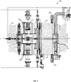
- cyclotron 200 including an RF resonator is depicted according to embodiments of the present invention.
- the cyclotron RF resonator includes a single shorting plate tuner 205 inside moveable tuner stem 215 and a fixed short 235 inside the fixed short stem 230.
- the design does not require top-bottom mirror symmetry.
- the maximum acceleration voltage is bound by the capacitance of the accelerating surfaces.
- cyclotron 200 may perform particle acceleration using asymmetrical tuning to reduce design complexity, cost of maintenance, fabrication and installation complexity, failure rate, and software complexity (e.g., control software), for example.
- fixed short 235 and fixed short stem 230 are depicted below dee 225, according to some embodiments, fixed short 235 and fixed short stem 230 may be located in another position (i.e., above dee 225).
- Fixed short stem 230 further includes inner conductor 220.
- the voltage distribution does not change, and the voltage maximum remains in middle position despite asymmetrical movement of the shorting plate tuner. Voltage is bound by capacitance of the accelerating surfaces, and a very small distance between dee 225 and an outer structure or liner of the resonator yields a relatively high capacitance.
- Cyclotron 200 further includes an iron magnet for shaping a magnetic field, a magnetic coil 255, an upper ion source 260, and a lower ion source 265.
- the iron magnet includes iron yoke ring 240, upper iron pole cap 245, and lower iron pole cap 250.
- the coil and iron components are used to produce and shape the magnetic field needed to accelerate particles inside the cyclotron.
- Upper pole cap 245 and lower pole cap 250 work in conjunction with yoke ring 240 to return the magnetic field lines.
- the ion sources 260 and 265 may comprise any particle source that produces charged particles for the accelerator, such as an external ion source with an injection system or an Electron Cyclotron Resonance (ECR) Ion Source.
- ECR Electron Cyclotron Resonance
- magnetic coil 255 is constructed from annealed copper, insulated with fiber-glass and covered with an epoxy resin.
- fixed short stem comprises a sliding shorting plate. According to other embodiments, fixed short stem comprises a bellowed stem. According to other embodiments, fixed short stem comprises a telescopic tube.
- FIG. 3 a diagram of a sectional view of an exemplary fixed stem 300 comprising a short flange is depicted for use with embodiments of the present invention.
- Figure 4 is a diagram of a back view of the exemplary fixed stem 300 for use with embodiments of the present invention.
- Fixed stem 300 is used for performing asymmetrical tuning using an RF cyclotron resonator, and is simpler in design, with fewer moving parts than traditional stem designs.
- the fixed stem 300 comprises no moving parts.
- Evaluation case 505 includes voltage measurements from an RF cyclotron resonator with unfixed tuners.
- Evaluation case 510 includes voltage measurements from an RF cyclotron resonator with fixed tuners.
- Evaluation case 515 includes voltage measurements from an RF cyclotron resonator with asymmetrically fixed tuners.
- a table 600 with exemplary Dees 1-4 at various positions using symmetrical and asymmetrically fixed tuners is depicted according to embodiments of the present invention. Extraction efficiencies of an accelerated beam were observed and a radial beam probe (RBP) scan was used to evaluate a change in the beam centering. As discussed above, embodiments of the present invention do not require top-bottom mirror symmetry. For small movements in relation to the wavelength, the maximum acceleration voltage is bound by the capacitance of the accelerating surfaces.
- FIG. 6B a table 650 of shorting plate positions for different Asum set points is depicted according to embodiments of the present invention, starting with activating the filed balance loop at 0.51 V Asum.
- An Asum value indicates the sum of amplitudes for four pickup voltages (one per Dee) divided by four. The Asum value may be considered a mean amplitude.
- Changes in field balance depicted in Figure 6B and the reaction of the field balance loop are caused by the iterative increase of the Asum from 0.51 V to 0.57 V, and finally to 0.69 V. After every step the field balance loop took roughly 5-6 minutes to stabilize tuner movement.
- the system took an average of 350 seconds for the tuners to reached stable relative positions after a restart of the RF system to full power. After that time the system reached a balanced field across the dees 1-4. For an Asum of 0.78 V, the System took an average of 350s until the tuners reached stable positions relative to each other after a restart of the RF system to full power.
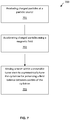
- a flowchart 700 depicting an exemplary sequence of steps for asymmetrically tuning a cyclotron is disclosed according to embodiments of the present invention.
- charged particles are produced at a particle source.
- the particle source may include any particle source that produces charged particles for an accelerator, such as an external ion source with an injection system or an ECR Ion Source, for example.
- the charged particles are accelerated using a magnetic field.
- the magnetic field is shaped using a magnet, and field lines of the magnet field are returned using an upper pole cap, a lower pole cap, and a yoke ring.
- a first tuner disposed within a moveable tuner stem is moved to asymmetrically tune the cyclotron for preserving a field balance between cavities of the cyclotron.
- a distance between the first tuner and a fixed tuner defines a resonance frequency of the cyclotron, and a maximum field produced by the cyclotron is independent from an asymmetrical movement of the tuner plate.
Landscapes
- Engineering & Computer Science (AREA)
- Physics & Mathematics (AREA)
- Plasma & Fusion (AREA)
- Spectroscopy & Molecular Physics (AREA)
- Health & Medical Sciences (AREA)
- Biomedical Technology (AREA)
- Pathology (AREA)
- Nuclear Medicine, Radiotherapy & Molecular Imaging (AREA)
- Radiology & Medical Imaging (AREA)
- Life Sciences & Earth Sciences (AREA)
- Animal Behavior & Ethology (AREA)
- General Health & Medical Sciences (AREA)
- Public Health (AREA)
- Veterinary Medicine (AREA)
- Particle Accelerators (AREA)
Description
- Embodiments of the present invention generally relate to the field of cyclotron resonators. More specifically, embodiments of the present invention relate to systems and methods for tuning RF cyclotron resonators.
- Standard radiation therapy using X-ray beams deposit their energy along the path of the beam to a target tumor. Particle therapy with protons or other ions is a type of radiotherapy that uses an external beam to provide targeted ionizing radiation to a tumor. Protons or other charged ions are sent to an accelerator to bring the particles' energy to a predetermined value. The protons or other ions then move through a beam-transport system, where magnets are used to shape, focus and/or direct the proton or other ion beam as necessary.
- Traditionally, one of the key design aspects of particle therapy is the use of symmetrical tuners in a cyclotron resonator. The cavities of cyclotrons, called Dees, are tuned for matching the cavity eigenmode to the RF-Signal of the RF-Power supply system and to preserve the field balance between the cavities. Some proton therapy systems use Hill-Number Ford rotational symmetry. In addition, all cyclotron are designed to obtain Top-Bottom mirror symmetry, where the mirror plane coincides with the beam plane. A RF resonator is used to produce a voltage to accelerate particles. Within the resonator tuners are used to control the resonance frequency. The maximum accelerating voltage is expected to be in the middle of the distance between two tuners. If only one of the tuners is moved, the maximum accelerating voltage moves away from the median plane which negatively affects acceleration performance of a cyclotron.
- R. Smythe, "A fractional turn injector cyclotron", Proceedings of the Fifth International Cyclotron conference, pages 95-100, discloses a traditional cyclotron RF resonator tuned by moving a shorting plane along a coaxial line.
- V. Savaiduc, "Resonator System for the BEST® 70 MeV Cyclotron", Proceedings of the XX International Conference on Cyclotrons and their Applications, discloses a cyclotron tuning system based on a mobile tuner and on a fixed tuner arranged along a horizontal plane of the cyclotron.
- The complexity of the cyclotron is increased greatly when both tuners need to be moved to maintain symmetry. For example, moveable sliding seals are used to separate atmospheric pressure from evacuated portions of the cyclotron. The use of a great number of moving parts increases the design complexity and the risk of failure of a moving part. Additionally, cyclotrons having symmetrical tuners require complex control software, especially when feedback loop algorithms are used for multi-dee cyclotrons. What is needed is a simplified high performance cyclotron that does not require complex control software and moving parts to reduce material, operation, and service costs of the cyclotron.
- Accordingly, a first aspect of the present invention provides a cyclotron radiofrequency (RF) resonator according to claim 1.
- Accordingly, a second aspect of the present invention defines a cyclotron according to
claim 2. - Accordingly, a third aspect of the present invention provides a method according to claim 9.
- Further aspects of the present invention are defined in the remaining claims.
- The accompanying drawings, which are incorporated in and form a part of this specification, illustrate embodiments of the invention and, together with the description, serve to explain the principles of the invention:
-
Figure 1 is a diagram depicting an exemplary cyclotron RF resonator. -
Figure 2 is a diagram of an exemplary cyclotron using an RF resonator with an asymmetrical tuner depicted according to embodiments of the present invention. -
Figure 3 is a diagram of a sectional view of an exemplary fixed stem comprising a short flange depicted according to embodiments of the present invention. -
Figure 4 is a diagram of a back view of an exemplary fixed stem depicted according to embodiments of the present invention. -
Figure 5 is a chart of exemplary measurement results from RF cyclotron resonators depicted according to embodiments of the present invention. -
Figure 6A is a table of positions of exemplary Dees 1-4 at various positions using symmetrical and asymmetrically fixed tuners depicted according to embodiments of the present invention. -
Figure 6B is a table of shorting plate positions and voltages for an Asum value of 0.51 depicted according to embodiments of the present invention -
Figure 7 is a flowchart depicting an exemplary sequence of steps for performing a method of asymmetrically tuning a cyclotron according to embodiments of the present invention. - Reference will now be made in detail to several embodiments. While the subject matter will be described in conjunction with the alternative embodiments, it will be understood that they are not intended to limit the claimed subject matter to these embodiments. The extent of the present invention remains determined by the appended claims.
- Furthermore, in the following detailed description, numerous specific details are set forth in order to provide a thorough understanding of the claimed subject matter. However, it will be recognized by one skilled in the art that other embodiments may be possible within the extent of the appended claims. In other instances, well-known methods, procedures, components, and circuits have not been described in detail as not to unnecessarily obscure aspects and features of the subject matter.
- Portions of the detailed description that follows are presented and discussed in terms of a method. Although steps and sequencing thereof are disclosed in a figure herein describing the operations of this method, such steps and sequencing are exemplary. Embodiments are well suited to performing various other steps or variations of the steps recited in the flowchart of the figures herein, and in a sequence other than that depicted and described herein.
- Some portions of the detailed description are presented in terms of procedures, steps, logic blocks, processing, and other symbolic representations of operations on data bits that can be performed on computer memory. These descriptions and representations are the means used by those skilled in the data processing arts to most effectively convey the substance of their work to others skilled in the art. A procedure, computer-executed step, logic block, process, etc., is here, and generally, conceived to be a self-consistent sequence of steps or instructions leading to a desired result. The steps are those requiring physical manipulations of physical quantities. Usually, though not necessarily, these quantities take the form of electrical or magnetic signals capable of being stored, transferred, combined, compared, and otherwise manipulated in a computer system. It has proven convenient at times, principally for reasons of common usage, to refer to these signals as bits, values, elements, symbols, characters, terms, numbers, or the like.
- It should be borne in mind, however, that all of these and similar terms are to be associated with the appropriate physical quantities and are merely convenient labels applied to these quantities. Unless specifically stated otherwise as apparent from the following discussions, it is appreciated that throughout, discussions utilizing terms such as "accessing," "writing," "including," "storing," "transmitting," "traversing," "associating," "identifying" or the like, refer to the action and processes of a computer system, or similar electronic computing device, that manipulates and transforms data represented as physical (electronic) quantities within the computer system's registers and memories into other data similarly represented as physical quantities within the computer system memories or registers or other such information storage, transmission or display devices.
- Some embodiments may be described in the general context of computer-executable instructions, such as program modules, executed by one or more computers or other devices. Generally, program modules include routines, programs, objects, components, data structures, etc. that perform particular tasks or implement particular abstract data types. Typically, the functionality of the program modules may be combined or distributed as desired in various embodiments.
- The following description is presented to enable a person skilled in the art to make and use the embodiments of this invention; it is presented in the context of a particular application and its requirements. Various modifications to the disclosed embodiments will be readily apparent to those skilled in the art, and the general principles defined herein may be applied to other embodiments and applications without departing from the scope of the present disclosure. Thus, the present invention is not limited to the embodiments shown, but is to be accorded the widest scope consistent with the principles and features disclosed herein within the scope of the appended claims.
- With regard to
Figure 1 , a diagram of an exemplarycyclotron RF resonator 100 is depicted. CyclotronRF resonator 100 includes a topshorting plate tuner 105 and a bottom shortingplate tuner 115 disposed insidemoveable tuner stem 110 andmoveable tuner stem 120, respectively. Moveable tuner stems 120 and 110 further includeinner conductor 130 connecting topshorting plate tuner 105 and a bottom shortingplate tuner 110 withdee 125.Dee 125 is positioned between top shortingplate tuner 105 and a bottom shortingplate tuner 115 for performing particle acceleration based on the position of topshorting plate tuner 105 and a bottom shortingplate tuner 115. Topshorting plate tuner 105 and a bottom shortingplate tuner 115 are moved up and down symmetrically in relation to a horizontal axis represented by the dotted line in the middle ofdee 125, where bringing the topshorting plate tuner 105 and a bottom shortingplate tuner 115 closer to or further fromdee 125 adjusts the resonance frequency ofcyclotron RF resonator 100. -
Graph 150 ofFigure 1 illustrates the acceleration voltage on the vertical axis (V) in relation to the position of the shorting plate tuners along the horizontal axis (X). At resonance frequency, given from the half wave length, the voltage distribution is depicted in the graph. The highest voltage is on the dashed median plane. At the positions of the shorts the voltage is zero. The graph also illustrates the alternating high frequency currents (I). When the middle region between the shortingplates - With regard to
Figure 2 , a diagram of anexemplary cyclotron 200 including an RF resonator is depicted according to embodiments of the present invention. The cyclotron RF resonator includes a singleshorting plate tuner 205 insidemoveable tuner stem 215 and a fixed short 235 inside the fixedshort stem 230. The design does not require top-bottom mirror symmetry. For small movements in relation to the wavelength, the maximum acceleration voltage is bound by the capacitance of the accelerating surfaces. As such,cyclotron 200 may perform particle acceleration using asymmetrical tuning to reduce design complexity, cost of maintenance, fabrication and installation complexity, failure rate, and software complexity (e.g., control software), for example. - Although the fixed short 235 and fixed
short stem 230 are depicted belowdee 225, according to some embodiments, fixed short 235 and fixedshort stem 230 may be located in another position (i.e., above dee 225). Fixedshort stem 230 further includesinner conductor 220. In some of the embodiments, the voltage distribution does not change, and the voltage maximum remains in middle position despite asymmetrical movement of the shorting plate tuner. Voltage is bound by capacitance of the accelerating surfaces, and a very small distance betweendee 225 and an outer structure or liner of the resonator yields a relatively high capacitance. -
Cyclotron 200 further includes an iron magnet for shaping a magnetic field, amagnetic coil 255, anupper ion source 260, and alower ion source 265. Specifically, according to some embodiments, the iron magnet includesiron yoke ring 240, upperiron pole cap 245, and loweriron pole cap 250. The coil and iron components are used to produce and shape the magnetic field needed to accelerate particles inside the cyclotron.Upper pole cap 245 andlower pole cap 250 work in conjunction withyoke ring 240 to return the magnetic field lines. The ion sources 260 and 265 may comprise any particle source that produces charged particles for the accelerator, such as an external ion source with an injection system or an Electron Cyclotron Resonance (ECR) Ion Source. - According to some embodiments,
magnetic coil 255 is constructed from annealed copper, insulated with fiber-glass and covered with an epoxy resin. - According to some embodiments, fixed short stem comprises a sliding shorting plate. According to other embodiments, fixed short stem comprises a bellowed stem. According to other embodiments, fixed short stem comprises a telescopic tube.
- With regard to
Figure 3 , a diagram of a sectional view of an exemplary fixedstem 300 comprising a short flange is depicted for use with embodiments of the present invention.Figure 4 is a diagram of a back view of the exemplary fixedstem 300 for use with embodiments of the present invention.Fixed stem 300 is used for performing asymmetrical tuning using an RF cyclotron resonator, and is simpler in design, with fewer moving parts than traditional stem designs. According to some embodiments, the fixedstem 300 comprises no moving parts. - With regard to
Figure 5 , achart 500 of exemplary measurement results from RF cyclotron resonators is depicted according to embodiments of the present invention.Evaluation case 505 includes voltage measurements from an RF cyclotron resonator with unfixed tuners.Evaluation case 510 includes voltage measurements from an RF cyclotron resonator with fixed tuners.Evaluation case 515 includes voltage measurements from an RF cyclotron resonator with asymmetrically fixed tuners. - With regard to
Figure 6A , a table 600 with exemplary Dees 1-4 at various positions using symmetrical and asymmetrically fixed tuners is depicted according to embodiments of the present invention. Extraction efficiencies of an accelerated beam were observed and a radial beam probe (RBP) scan was used to evaluate a change in the beam centering. As discussed above, embodiments of the present invention do not require top-bottom mirror symmetry. For small movements in relation to the wavelength, the maximum acceleration voltage is bound by the capacitance of the accelerating surfaces. - Like with symmetrically fixed tuners, for asymmetrically fixed tuners, no unusual behavior of the tuner positioning was caused by the field balance loop or the matching loop. At the 14:28 timestamp, half of the tuners are static. At timestamp 14:56, the field balance loop was activated and regulated the dee voltages in balance within five minutes. Regulation behavior from the field balance loop shows no negative effects caused by fixed tuners. Performing particle acceleration using asymmetrical tuning reduces design complexity, the cost of maintenance, fabrication and installation complexity, failure rate, and software complexity (e.g., control software), for example.
- With regard to
Figure 6B , a table 650 of shorting plate positions for different Asum set points is depicted according to embodiments of the present invention, starting with activating the filed balance loop at 0.51 V Asum. An Asum value indicates the sum of amplitudes for four pickup voltages (one per Dee) divided by four. The Asum value may be considered a mean amplitude. Changes in field balance depicted inFigure 6B and the reaction of the field balance loop are caused by the iterative increase of the Asum from 0.51 V to 0.57 V, and finally to 0.69 V. After every step the field balance loop took roughly 5-6 minutes to stabilize tuner movement. - For an Asum of 0.51 V, the system took an average of 350 seconds for the tuners to reached stable relative positions after a restart of the RF system to full power. After that time the system reached a balanced field across the dees 1-4. For an Asum of 0.78 V, the System took an average of 350s until the tuners reached stable positions relative to each other after a restart of the RF system to full power.
- With regard to
Figure 7 , aflowchart 700 depicting an exemplary sequence of steps for asymmetrically tuning a cyclotron is disclosed according to embodiments of the present invention. Atstep 701, charged particles are produced at a particle source. The particle source may include any particle source that produces charged particles for an accelerator, such as an external ion source with an injection system or an ECR Ion Source, for example. - At
step 702, the charged particles are accelerated using a magnetic field. According to some embodiments, the magnetic field is shaped using a magnet, and field lines of the magnet field are returned using an upper pole cap, a lower pole cap, and a yoke ring. - At
step 703, a first tuner disposed within a moveable tuner stem is moved to asymmetrically tune the cyclotron for preserving a field balance between cavities of the cyclotron. As described above, a distance between the first tuner and a fixed tuner defines a resonance frequency of the cyclotron, and a maximum field produced by the cyclotron is independent from an asymmetrical movement of the tuner plate. - Embodiments of the present invention are thus described. While the present invention has been described in particular embodiments, it should be appreciated that the present invention should not be construed as limited by such embodiments, but rather construed according to the following claims.
Claims (13)
- A cyclotron radiofrequency (RF) resonator comprising:a vacuum chamber having a median plane defining a top-bottom mirror symmetry;a fixed short stem (230) coupled to the vacuum chamber anda fixed short (235) disposed within the fixed short stem (230),a movable tuner stem (215) coupled to the vacuum chamber and a singleshorting plate tuner (205) disposed within the movable tuner stem (215),a radio frequency resonator dee (225) disposed within said vacuum chamber for producing an alternating electric field using the vacuum chamber,wherein said single shorting plate tuner (205) is configured to be moved to asymmetrically tune said cyclotron RF resonator based on a distance between said fixed short (235) and said single shorting plate (205) without top-bottom mirror symmetry;wherein the respective longitudinal axis- of the movable tuner stem (215);- of the single shorting plate tuner (205);- of the fixed short stem (230);- of the fixed short (235);are aligned with each other along a common longitudinal axis,said common longitudinal axis being parallel to a longitudinal axis of said vacuum chamber orthogonal to said median plane.
- A cyclotron (200) comprising:a main coil (255) for producing a magnetic field;an iron magnet (240) surrounding the main coil (255) for shaping the magnetic field;said cyclotron (200)characterised bya cyclotron radiofrequency (RF) resonator according to claim 1.
- The cyclotron (200) of Claim 2, wherein the fixed short stem (230) comprises only fixed parts, and/or wherein the fixed short stem (230) is disposed above below the vacuum chamber.
- The cyclotron (200) of Claim 2, wherein the iron magnet (240) comprises a top iron magnet, a bottom iron magnet, and an opening between the top iron magnet and the bottom iron magnet disposed on said median plane.
- The cyclotron (200) of Claim 2, wherein the iron magnet comprises a yoke ring (240), a lower pole cap (250), and an upper pole cap (245), wherein the yoke ring (240), the lower pole cap (250), and the upper pole cap (245) are configured to to return magnetic field lines of the magnetic field.
- The cyclotron (200) of Claim 2, wherein the cyclotron radiofrequency (RF) resonator is adapted to produce an acceleration voltage based on the position of the single shorting plate tuner (205), and/or a movement of said single shorting plate tuner (205) is small compared to the wavelength of the radiofrequency such that a maximum acceleration voltage of the cyclotron radiofrequency (RF) resonator is bound by a capacitance of the cyclotron radiofrequency (RF) resonator.
- The cyclotron (200) of Claim 2, wherein the single shorting tuner plate (205) is disposed below or above the cyclotron radiofrequency (RF) resonator.
- The cyclotron (200) of Claim 2, wherein a movement of said single shorting plate tuner (205) is small compared to the wavelength of the radiofrequency such that a maximum acceleration voltage of the cyclotron (200) is bound by a capacitance of the cyclotron radiofrequency (RF) resonator, and/or wherein the cyclotron (200) further comprises an inner conductor (205) inside the fixed short stem (230) disposed between the tuner plate (205) and the vacuum chamber.
- A method (700) for asymmetrically tuning a cyclotron (200) according to any one of claims 2 to 8, said cyclotron further comprising a plurality of cavities,
the method comprising:(701) producing charged particles at a particle source (260, (265);(702) accelerating the charged particles using said magnetic field;
and(703) moving said single shorting plate tuner (205) to asymmetrically tune said cyclotron radiofrequency (RF) resonator based on said distance between said fixed short (235) and single shorting plate (205) without top-bottom mirror symmetry for preserving a field balance between said cavities of the cyclotron (200),wherein a distance between the single shorting plate tuner (205) and the fixed short (235) defines resonance frequency of the cyclotron radiofrequency (RF) resonator, and
wherein the movement of the single shorting plate tuner (205) is small compared to the wavelength of the radiofrequency (RF), such that a maximum field produced by the cyclotron is bound by the capacitance of an accelerating surface of the cyclotron and independent from an asymmetrical movement of the single shorting plate tuner (205). - The method of Claim 9, further comprising shaping the magnetic field using said iron magnet, wherein field lines of the magnet field are returned using said upper pole cap (245), said lower pole cap (250), and said yoke ring (240).
- The method of Claim 9, wherein a maximum acceleration voltage produced by the cyclotron (200) is bound by a capacitance of accelerating surfaces of the cyclotron (200).
- The method of Claim 9, wherein the particle source (260, 265) comprises an external ion source and an injection system and/or comprises an electron cyclotron resonance (ECR) ion source.
- The method of Claim 9, wherein the fixed short stem (230) comprises a conductor.
Applications Claiming Priority (2)
| Application Number | Priority Date | Filing Date | Title |
|---|---|---|---|
| US15/399,528 US10306746B2 (en) | 2017-01-05 | 2017-01-05 | Cyclotron RF resonator tuning with asymmetrical fixed tuner |
| PCT/EP2018/050212 WO2018127537A1 (en) | 2017-01-05 | 2018-01-04 | Cyclotron rf resonator tuning with asymmetrical fixed tuner |
Publications (2)
| Publication Number | Publication Date |
|---|---|
| EP3549410A1 EP3549410A1 (en) | 2019-10-09 |
| EP3549410B1 true EP3549410B1 (en) | 2021-04-21 |
Family
ID=60935889
Family Applications (1)
| Application Number | Title | Priority Date | Filing Date |
|---|---|---|---|
| EP18700059.1A Active EP3549410B1 (en) | 2017-01-05 | 2018-01-04 | Cyclotron rf resonator with asymmetrical tuning |
Country Status (3)
| Country | Link |
|---|---|
| US (1) | US10306746B2 (en) |
| EP (1) | EP3549410B1 (en) |
| WO (1) | WO2018127537A1 (en) |
Families Citing this family (2)
| Publication number | Priority date | Publication date | Assignee | Title |
|---|---|---|---|---|
| CN116939941B (en) * | 2023-08-30 | 2026-04-21 | 中国原子能科学研究院 | An irregularly shaped connection structure for an inner rod in a desktop cyclotron. |
| CN117439341B (en) * | 2023-10-19 | 2024-04-26 | 国电投核力同创(北京)科技有限公司 | Cyclotron frequency tuning device based on electric push cylinder structure |
Family Cites Families (10)
| Publication number | Priority date | Publication date | Assignee | Title |
|---|---|---|---|---|
| CA966893A (en) * | 1973-06-19 | 1975-04-29 | Her Majesty In Right Of Canada As Represented By Atomic Energy Of Canada Limited | Superconducting cyclotron |
| ZA757266B (en) | 1975-11-19 | 1977-09-28 | W Rautenbach | Cyclotron and neutron therapy installation incorporating such a cyclotron |
| US4728910A (en) * | 1986-10-27 | 1988-03-01 | The United States Of America As Represented By The United States Department Of Energy | Folded waveguide coupler |
| US6262638B1 (en) * | 1998-09-28 | 2001-07-17 | Axcelis Technologies, Inc. | Tunable and matchable resonator coil assembly for ion implanter linear accelerator |
| EP2410823B1 (en) * | 2010-07-22 | 2012-11-28 | Ion Beam Applications | Cyclotron for accelerating at least two kinds of particles |
| US8653762B2 (en) | 2010-12-23 | 2014-02-18 | General Electric Company | Particle accelerators having electromechanical motors and methods of operating and manufacturing the same |
| CN104813749B (en) * | 2012-09-28 | 2019-07-02 | 梅维昂医疗系统股份有限公司 | Control the intensity of the particle beam |
| JP6038682B2 (en) | 2013-02-20 | 2016-12-07 | 住友重機械工業株式会社 | cyclotron |
| CN106231775B (en) | 2016-07-29 | 2018-10-09 | 中国原子能科学研究院 | A kind of superconducting cyclotron Y structure interior bar spiral shape cavity |
| CN106231774B (en) | 2016-07-29 | 2018-10-09 | 中国原子能科学研究院 | A kind of high frequency cavity and its working frequency adjusting method with compensating electric capacity |
-
2017
- 2017-01-05 US US15/399,528 patent/US10306746B2/en active Active
-
2018
- 2018-01-04 EP EP18700059.1A patent/EP3549410B1/en active Active
- 2018-01-04 WO PCT/EP2018/050212 patent/WO2018127537A1/en not_active Ceased
Non-Patent Citations (1)
| Title |
|---|
| None * |
Also Published As
| Publication number | Publication date |
|---|---|
| WO2018127537A1 (en) | 2018-07-12 |
| EP3549410A1 (en) | 2019-10-09 |
| US10306746B2 (en) | 2019-05-28 |
| US20180192506A1 (en) | 2018-07-05 |
Similar Documents
| Publication | Publication Date | Title |
|---|---|---|
| US11596051B2 (en) | Resonator, linear accelerator configuration and ion implantation system having toroidal resonator | |
| JPH02501965A (en) | Electron cyclotron resonance plasma source | |
| US20150084548A1 (en) | Circular accelerator | |
| Ruess et al. | An inverse magnetron injection gun for the KIT 2-MW coaxial-cavity gyrotron | |
| US6445146B1 (en) | Method of reducing axial beam focusing | |
| US12324088B2 (en) | Ion source, circular accelerator using same, and particle beam therapy system | |
| US10306746B2 (en) | Cyclotron RF resonator tuning with asymmetrical fixed tuner | |
| Kojima et al. | Achievement and improvement of the JT-60U negative ion source for JT-60 Super Advanced | |
| Sayapin et al. | $ S $-Band Relativistic Magnetron Operation With Multichannel Radial Outputs of the Microwave Power | |
| Sun et al. | A high charge state all-permanent magnet ECR ion source for the IMP 320 kV HV platform | |
| KR20230128516A (en) | Ion source device with controllable plasma density | |
| Goswami et al. | Design of a spiral inflector and transverse beam matching for K130 cyclotron at the Variable Energy Cyclotron Centre | |
| Du et al. | Beam dynamics, RF measurement, and commissioning of a CW heavy ion IH-DTL | |
| Wang et al. | Computer design of a compact cyclotron | |
| CN116417317A (en) | A Structure for Improving the Acceleration Efficiency of Radio Frequency Acceleration Barrel in Ion Implantation System | |
| Gikal et al. | Development, creation, and startup of the DC-110 heavy ion cyclotron complex for industrial production of track membranes | |
| WO2018096648A1 (en) | Accelerator and particle beam irradiation device | |
| Bandyopadhyay et al. | Design of a Ku band miniature multiple beam klystron | |
| Willeke | Study of a Fixed Field Accelerator as a Driver for Proton Driven Plasma Wakefield Acceleration | |
| Dong et al. | Design of a novel MIG for a 140-GHz 2-kW confocal gyrotron traveling-wave tube | |
| KR102860911B1 (en) | Hybrid magnet structure | |
| Wang et al. | Breakdown assisted by a novel electron drift injection in the J-TEXT tokamak | |
| Basten et al. | R& D status of the new superconducting cw heavy ion LINAC@ GSI | |
| Manuilov et al. | Third harmonic CW gyrotron with operating frequency 1.2 THz for a DNP/NMA spectroscopy | |
| US3528034A (en) | Establishment of harmonic frequencies in a penning-type discharge |
Legal Events
| Date | Code | Title | Description |
|---|---|---|---|
| STAA | Information on the status of an ep patent application or granted ep patent |
Free format text: STATUS: UNKNOWN |
|
| STAA | Information on the status of an ep patent application or granted ep patent |
Free format text: STATUS: THE INTERNATIONAL PUBLICATION HAS BEEN MADE |
|
| PUAI | Public reference made under article 153(3) epc to a published international application that has entered the european phase |
Free format text: ORIGINAL CODE: 0009012 |
|
| STAA | Information on the status of an ep patent application or granted ep patent |
Free format text: STATUS: REQUEST FOR EXAMINATION WAS MADE |
|
| 17P | Request for examination filed |
Effective date: 20190704 |
|
| AK | Designated contracting states |
Kind code of ref document: A1 Designated state(s): AL AT BE BG CH CY CZ DE DK EE ES FI FR GB GR HR HU IE IS IT LI LT LU LV MC MK MT NL NO PL PT RO RS SE SI SK SM TR |
|
| AX | Request for extension of the european patent |
Extension state: BA ME |
|
| DAV | Request for validation of the european patent (deleted) | ||
| DAX | Request for extension of the european patent (deleted) | ||
| GRAP | Despatch of communication of intention to grant a patent |
Free format text: ORIGINAL CODE: EPIDOSNIGR1 |
|
| STAA | Information on the status of an ep patent application or granted ep patent |
Free format text: STATUS: GRANT OF PATENT IS INTENDED |
|
| INTG | Intention to grant announced |
Effective date: 20201130 |
|
| GRAS | Grant fee paid |
Free format text: ORIGINAL CODE: EPIDOSNIGR3 |
|
| GRAA | (expected) grant |
Free format text: ORIGINAL CODE: 0009210 |
|
| STAA | Information on the status of an ep patent application or granted ep patent |
Free format text: STATUS: THE PATENT HAS BEEN GRANTED |
|
| RAP3 | Party data changed (applicant data changed or rights of an application transferred) |
Owner name: VARIAN MEDICAL SYSTEMS PARTICLE THERAPY GMBH & CO. KG |
|
| AK | Designated contracting states |
Kind code of ref document: B1 Designated state(s): AL AT BE BG CH CY CZ DE DK EE ES FI FR GB GR HR HU IE IS IT LI LT LU LV MC MK MT NL NO PL PT RO RS SE SI SK SM TR |
|
| REG | Reference to a national code |
Ref country code: GB Ref legal event code: FG4D |
|
| REG | Reference to a national code |
Ref country code: CH Ref legal event code: EP |
|
| REG | Reference to a national code |
Ref country code: DE Ref legal event code: R096 Ref document number: 602018015819 Country of ref document: DE Ref country code: IE Ref legal event code: FG4D |
|
| REG | Reference to a national code |
Ref country code: AT Ref legal event code: REF Ref document number: 1386015 Country of ref document: AT Kind code of ref document: T Effective date: 20210515 |
|
| REG | Reference to a national code |
Ref country code: LT Ref legal event code: MG9D |
|
| REG | Reference to a national code |
Ref country code: AT Ref legal event code: MK05 Ref document number: 1386015 Country of ref document: AT Kind code of ref document: T Effective date: 20210421 |
|
| REG | Reference to a national code |
Ref country code: NL Ref legal event code: MP Effective date: 20210421 |
|
| PG25 | Lapsed in a contracting state [announced via postgrant information from national office to epo] |
Ref country code: FI Free format text: LAPSE BECAUSE OF FAILURE TO SUBMIT A TRANSLATION OF THE DESCRIPTION OR TO PAY THE FEE WITHIN THE PRESCRIBED TIME-LIMIT Effective date: 20210421 Ref country code: LT Free format text: LAPSE BECAUSE OF FAILURE TO SUBMIT A TRANSLATION OF THE DESCRIPTION OR TO PAY THE FEE WITHIN THE PRESCRIBED TIME-LIMIT Effective date: 20210421 Ref country code: HR Free format text: LAPSE BECAUSE OF FAILURE TO SUBMIT A TRANSLATION OF THE DESCRIPTION OR TO PAY THE FEE WITHIN THE PRESCRIBED TIME-LIMIT Effective date: 20210421 Ref country code: NL Free format text: LAPSE BECAUSE OF FAILURE TO SUBMIT A TRANSLATION OF THE DESCRIPTION OR TO PAY THE FEE WITHIN THE PRESCRIBED TIME-LIMIT Effective date: 20210421 Ref country code: BG Free format text: LAPSE BECAUSE OF FAILURE TO SUBMIT A TRANSLATION OF THE DESCRIPTION OR TO PAY THE FEE WITHIN THE PRESCRIBED TIME-LIMIT Effective date: 20210721 Ref country code: AT Free format text: LAPSE BECAUSE OF FAILURE TO SUBMIT A TRANSLATION OF THE DESCRIPTION OR TO PAY THE FEE WITHIN THE PRESCRIBED TIME-LIMIT Effective date: 20210421 |
|
| PG25 | Lapsed in a contracting state [announced via postgrant information from national office to epo] |
Ref country code: NO Free format text: LAPSE BECAUSE OF FAILURE TO SUBMIT A TRANSLATION OF THE DESCRIPTION OR TO PAY THE FEE WITHIN THE PRESCRIBED TIME-LIMIT Effective date: 20210721 Ref country code: LV Free format text: LAPSE BECAUSE OF FAILURE TO SUBMIT A TRANSLATION OF THE DESCRIPTION OR TO PAY THE FEE WITHIN THE PRESCRIBED TIME-LIMIT Effective date: 20210421 Ref country code: PL Free format text: LAPSE BECAUSE OF FAILURE TO SUBMIT A TRANSLATION OF THE DESCRIPTION OR TO PAY THE FEE WITHIN THE PRESCRIBED TIME-LIMIT Effective date: 20210421 Ref country code: PT Free format text: LAPSE BECAUSE OF FAILURE TO SUBMIT A TRANSLATION OF THE DESCRIPTION OR TO PAY THE FEE WITHIN THE PRESCRIBED TIME-LIMIT Effective date: 20210823 Ref country code: RS Free format text: LAPSE BECAUSE OF FAILURE TO SUBMIT A TRANSLATION OF THE DESCRIPTION OR TO PAY THE FEE WITHIN THE PRESCRIBED TIME-LIMIT Effective date: 20210421 Ref country code: SE Free format text: LAPSE BECAUSE OF FAILURE TO SUBMIT A TRANSLATION OF THE DESCRIPTION OR TO PAY THE FEE WITHIN THE PRESCRIBED TIME-LIMIT Effective date: 20210421 Ref country code: GR Free format text: LAPSE BECAUSE OF FAILURE TO SUBMIT A TRANSLATION OF THE DESCRIPTION OR TO PAY THE FEE WITHIN THE PRESCRIBED TIME-LIMIT Effective date: 20210722 Ref country code: IS Free format text: LAPSE BECAUSE OF FAILURE TO SUBMIT A TRANSLATION OF THE DESCRIPTION OR TO PAY THE FEE WITHIN THE PRESCRIBED TIME-LIMIT Effective date: 20210821 |
|
| REG | Reference to a national code |
Ref country code: DE Ref legal event code: R097 Ref document number: 602018015819 Country of ref document: DE |
|
| PG25 | Lapsed in a contracting state [announced via postgrant information from national office to epo] |
Ref country code: EE Free format text: LAPSE BECAUSE OF FAILURE TO SUBMIT A TRANSLATION OF THE DESCRIPTION OR TO PAY THE FEE WITHIN THE PRESCRIBED TIME-LIMIT Effective date: 20210421 Ref country code: ES Free format text: LAPSE BECAUSE OF FAILURE TO SUBMIT A TRANSLATION OF THE DESCRIPTION OR TO PAY THE FEE WITHIN THE PRESCRIBED TIME-LIMIT Effective date: 20210421 Ref country code: SK Free format text: LAPSE BECAUSE OF FAILURE TO SUBMIT A TRANSLATION OF THE DESCRIPTION OR TO PAY THE FEE WITHIN THE PRESCRIBED TIME-LIMIT Effective date: 20210421 Ref country code: SM Free format text: LAPSE BECAUSE OF FAILURE TO SUBMIT A TRANSLATION OF THE DESCRIPTION OR TO PAY THE FEE WITHIN THE PRESCRIBED TIME-LIMIT Effective date: 20210421 Ref country code: RO Free format text: LAPSE BECAUSE OF FAILURE TO SUBMIT A TRANSLATION OF THE DESCRIPTION OR TO PAY THE FEE WITHIN THE PRESCRIBED TIME-LIMIT Effective date: 20210421 Ref country code: DK Free format text: LAPSE BECAUSE OF FAILURE TO SUBMIT A TRANSLATION OF THE DESCRIPTION OR TO PAY THE FEE WITHIN THE PRESCRIBED TIME-LIMIT Effective date: 20210421 Ref country code: CZ Free format text: LAPSE BECAUSE OF FAILURE TO SUBMIT A TRANSLATION OF THE DESCRIPTION OR TO PAY THE FEE WITHIN THE PRESCRIBED TIME-LIMIT Effective date: 20210421 |
|
| PLBE | No opposition filed within time limit |
Free format text: ORIGINAL CODE: 0009261 |
|
| STAA | Information on the status of an ep patent application or granted ep patent |
Free format text: STATUS: NO OPPOSITION FILED WITHIN TIME LIMIT |
|
| 26N | No opposition filed |
Effective date: 20220124 |
|
| PG25 | Lapsed in a contracting state [announced via postgrant information from national office to epo] |
Ref country code: IS Free format text: LAPSE BECAUSE OF FAILURE TO SUBMIT A TRANSLATION OF THE DESCRIPTION OR TO PAY THE FEE WITHIN THE PRESCRIBED TIME-LIMIT Effective date: 20210821 Ref country code: AL Free format text: LAPSE BECAUSE OF FAILURE TO SUBMIT A TRANSLATION OF THE DESCRIPTION OR TO PAY THE FEE WITHIN THE PRESCRIBED TIME-LIMIT Effective date: 20210421 |
|
| PG25 | Lapsed in a contracting state [announced via postgrant information from national office to epo] |
Ref country code: IT Free format text: LAPSE BECAUSE OF FAILURE TO SUBMIT A TRANSLATION OF THE DESCRIPTION OR TO PAY THE FEE WITHIN THE PRESCRIBED TIME-LIMIT Effective date: 20210421 |
|
| PG25 | Lapsed in a contracting state [announced via postgrant information from national office to epo] |
Ref country code: MC Free format text: LAPSE BECAUSE OF FAILURE TO SUBMIT A TRANSLATION OF THE DESCRIPTION OR TO PAY THE FEE WITHIN THE PRESCRIBED TIME-LIMIT Effective date: 20210421 |
|
| REG | Reference to a national code |
Ref country code: CH Ref legal event code: PL |
|
| REG | Reference to a national code |
Ref country code: BE Ref legal event code: MM Effective date: 20220131 |
|
| PG25 | Lapsed in a contracting state [announced via postgrant information from national office to epo] |
Ref country code: LU Free format text: LAPSE BECAUSE OF NON-PAYMENT OF DUE FEES Effective date: 20220104 |
|
| PG25 | Lapsed in a contracting state [announced via postgrant information from national office to epo] |
Ref country code: FR Free format text: LAPSE BECAUSE OF NON-PAYMENT OF DUE FEES Effective date: 20220131 Ref country code: BE Free format text: LAPSE BECAUSE OF NON-PAYMENT OF DUE FEES Effective date: 20220131 |
|
| PG25 | Lapsed in a contracting state [announced via postgrant information from national office to epo] |
Ref country code: LI Free format text: LAPSE BECAUSE OF NON-PAYMENT OF DUE FEES Effective date: 20220131 Ref country code: CH Free format text: LAPSE BECAUSE OF NON-PAYMENT OF DUE FEES Effective date: 20220131 |
|
| PG25 | Lapsed in a contracting state [announced via postgrant information from national office to epo] |
Ref country code: IE Free format text: LAPSE BECAUSE OF NON-PAYMENT OF DUE FEES Effective date: 20220104 |
|
| PG25 | Lapsed in a contracting state [announced via postgrant information from national office to epo] |
Ref country code: MK Free format text: LAPSE BECAUSE OF FAILURE TO SUBMIT A TRANSLATION OF THE DESCRIPTION OR TO PAY THE FEE WITHIN THE PRESCRIBED TIME-LIMIT Effective date: 20210421 Ref country code: CY Free format text: LAPSE BECAUSE OF FAILURE TO SUBMIT A TRANSLATION OF THE DESCRIPTION OR TO PAY THE FEE WITHIN THE PRESCRIBED TIME-LIMIT Effective date: 20210421 |
|
| PG25 | Lapsed in a contracting state [announced via postgrant information from national office to epo] |
Ref country code: HU Free format text: LAPSE BECAUSE OF FAILURE TO SUBMIT A TRANSLATION OF THE DESCRIPTION OR TO PAY THE FEE WITHIN THE PRESCRIBED TIME-LIMIT; INVALID AB INITIO Effective date: 20180104 |
|
| PG25 | Lapsed in a contracting state [announced via postgrant information from national office to epo] |
Ref country code: TR Free format text: LAPSE BECAUSE OF FAILURE TO SUBMIT A TRANSLATION OF THE DESCRIPTION OR TO PAY THE FEE WITHIN THE PRESCRIBED TIME-LIMIT Effective date: 20210421 |
|
| PG25 | Lapsed in a contracting state [announced via postgrant information from national office to epo] |
Ref country code: MT Free format text: LAPSE BECAUSE OF FAILURE TO SUBMIT A TRANSLATION OF THE DESCRIPTION OR TO PAY THE FEE WITHIN THE PRESCRIBED TIME-LIMIT Effective date: 20210421 |
|
| PGFP | Annual fee paid to national office [announced via postgrant information from national office to epo] |
Ref country code: GB Payment date: 20260210 Year of fee payment: 9 |
|
| PGFP | Annual fee paid to national office [announced via postgrant information from national office to epo] |
Ref country code: DE Payment date: 20260320 Year of fee payment: 9 |