EP3549403B1 - Beleuchtungssystem - Google Patents
Beleuchtungssystem Download PDFInfo
- Publication number
- EP3549403B1 EP3549403B1 EP17812083.8A EP17812083A EP3549403B1 EP 3549403 B1 EP3549403 B1 EP 3549403B1 EP 17812083 A EP17812083 A EP 17812083A EP 3549403 B1 EP3549403 B1 EP 3549403B1
- Authority
- EP
- European Patent Office
- Prior art keywords
- terminal
- positive terminal
- lighting module
- terminals
- lighting
- Prior art date
- Legal status (The legal status is an assumption and is not a legal conclusion. Google has not performed a legal analysis and makes no representation as to the accuracy of the status listed.)
- Active
Links
Images



Classifications
-
- F—MECHANICAL ENGINEERING; LIGHTING; HEATING; WEAPONS; BLASTING
- F21—LIGHTING
- F21S—NON-PORTABLE LIGHTING DEVICES; SYSTEMS THEREOF; VEHICLE LIGHTING DEVICES SPECIALLY ADAPTED FOR VEHICLE EXTERIORS
- F21S4/00—Lighting devices or systems using a string or strip of light sources
- F21S4/20—Lighting devices or systems using a string or strip of light sources with light sources held by or within elongate supports
- F21S4/28—Lighting devices or systems using a string or strip of light sources with light sources held by or within elongate supports rigid, e.g. LED bars
-
- F—MECHANICAL ENGINEERING; LIGHTING; HEATING; WEAPONS; BLASTING
- F21—LIGHTING
- F21V—FUNCTIONAL FEATURES OR DETAILS OF LIGHTING DEVICES OR SYSTEMS THEREOF; STRUCTURAL COMBINATIONS OF LIGHTING DEVICES WITH OTHER ARTICLES, NOT OTHERWISE PROVIDED FOR
- F21V23/00—Arrangement of electric circuit elements in or on lighting devices
- F21V23/003—Arrangement of electric circuit elements in or on lighting devices the elements being electronics drivers or controllers for operating the light source, e.g. for a LED array
- F21V23/004—Arrangement of electric circuit elements in or on lighting devices the elements being electronics drivers or controllers for operating the light source, e.g. for a LED array arranged on a substrate, e.g. a printed circuit board
- F21V23/005—Arrangement of electric circuit elements in or on lighting devices the elements being electronics drivers or controllers for operating the light source, e.g. for a LED array arranged on a substrate, e.g. a printed circuit board the substrate is supporting also the light source
-
- H—ELECTRICITY
- H05—ELECTRIC TECHNIQUES NOT OTHERWISE PROVIDED FOR
- H05B—ELECTRIC HEATING; ELECTRIC LIGHT SOURCES NOT OTHERWISE PROVIDED FOR; CIRCUIT ARRANGEMENTS FOR ELECTRIC LIGHT SOURCES, IN GENERAL
- H05B45/00—Circuit arrangements for operating light-emitting diodes [LED]
- H05B45/30—Driver circuits
- H05B45/37—Converter circuits
- H05B45/3725—Switched mode power supply [SMPS]
-
- H—ELECTRICITY
- H05—ELECTRIC TECHNIQUES NOT OTHERWISE PROVIDED FOR
- H05B—ELECTRIC HEATING; ELECTRIC LIGHT SOURCES NOT OTHERWISE PROVIDED FOR; CIRCUIT ARRANGEMENTS FOR ELECTRIC LIGHT SOURCES, IN GENERAL
- H05B45/00—Circuit arrangements for operating light-emitting diodes [LED]
- H05B45/30—Driver circuits
- H05B45/395—Linear regulators
-
- F—MECHANICAL ENGINEERING; LIGHTING; HEATING; WEAPONS; BLASTING
- F21—LIGHTING
- F21Y—INDEXING SCHEME ASSOCIATED WITH SUBCLASSES F21K, F21L, F21S and F21V, RELATING TO THE FORM OR THE KIND OF THE LIGHT SOURCES OR OF THE COLOUR OF THE LIGHT EMITTED
- F21Y2103/00—Elongate light sources, e.g. fluorescent tubes
- F21Y2103/10—Elongate light sources, e.g. fluorescent tubes comprising a linear array of point-like light-generating elements
-
- F—MECHANICAL ENGINEERING; LIGHTING; HEATING; WEAPONS; BLASTING
- F21—LIGHTING
- F21Y—INDEXING SCHEME ASSOCIATED WITH SUBCLASSES F21K, F21L, F21S and F21V, RELATING TO THE FORM OR THE KIND OF THE LIGHT SOURCES OR OF THE COLOUR OF THE LIGHT EMITTED
- F21Y2115/00—Light-generating elements of semiconductor light sources
- F21Y2115/10—Light-emitting diodes [LED]
-
- Y—GENERAL TAGGING OF NEW TECHNOLOGICAL DEVELOPMENTS; GENERAL TAGGING OF CROSS-SECTIONAL TECHNOLOGIES SPANNING OVER SEVERAL SECTIONS OF THE IPC; TECHNICAL SUBJECTS COVERED BY FORMER USPC CROSS-REFERENCE ART COLLECTIONS [XRACs] AND DIGESTS
- Y02—TECHNOLOGIES OR APPLICATIONS FOR MITIGATION OR ADAPTATION AGAINST CLIMATE CHANGE
- Y02B—CLIMATE CHANGE MITIGATION TECHNOLOGIES RELATED TO BUILDINGS, e.g. HOUSING, HOUSE APPLIANCES OR RELATED END-USER APPLICATIONS
- Y02B20/00—Energy efficient lighting technologies, e.g. halogen lamps or gas discharge lamps
- Y02B20/30—Semiconductor lamps, e.g. solid state lamps [SSL] light emitting diodes [LED] or organic LED [OLED]
Definitions
- the electronic converter 10 usually includes an AC/DC or DC/DC switched mode power supply, which receives at input a supply signal (e.g. from the mains or from a battery) and provides at output, through a power output including a positive terminal 100a and a negative terminal 100b, which constitutes a ground GND, a regulated voltage V out or a regulated current i out .
- a supply signal e.g. from the mains or from a battery
- a power output including a positive terminal 100a and a negative terminal 100b, which constitutes a ground GND, a regulated voltage V out or a regulated current i out .
- Each lighting module 20 includes one or more light radiation sources including e.g. at least one LED (Light Emitting Diode) or other solid-state lighting means, such as laser diodes.
- LED Light Emitting Diode
- other solid-state lighting means such as laser diodes.
- lighting module 20 is a LED module including one or more LEDs L, connected between the terminals 200a and 200b.
- module 20 may include a LED chain or string 22, wherein a plurality of LEDs L are connected in series.
- the LEDs L may also be distributed along various branches connected in parallel.
- module 20 may include a first LED string 22a including a first set of LEDs L connected in series, and a second LED string 22b including a second set of LEDs L connected in series.
- the LED strings 22 may differ from each other for various reasons, e.g. as regards the number and the type of the LEDs, the operating temperature and other parameters, so that the voltage across one string may be different from the voltage across the other string(s). For this reason, the solution of directly connecting the strings 22 to each other in parallel is often unfeasible, because the electrical power supply is distributed in an uncontrolled fashion among the various strings.
- the electronic converter 10 may provide a regulated voltage V out , such as for example 12, 24, 48 VDC.
- the lighting module 20 includes a current regulator 24, connected in series with each LED string 22.
- a current regulator 24 connected in series with each LED string 22.
- the first LED string 22a and a first current regulator 24a are connected (e.g. directly) in series between terminals 200a and 200b
- the second LED string 22b and a second current regulator 24b are connected (e.g. directly) in series between terminals 200a and 200b.
- the strings 22a and 22b are powered by means of a common voltage ( V out ).
- V out a common voltage
- the LED strings 22 with the respective current regulators 24 included in the various lighting modules 20 should be connected in parallel at the voltage V out provided by electronic converter 10.
- the lighting modules 20 should be electrically connected in parallel to the voltage V out .
- lighting module 20 1 also includes a positive output terminal 200c and a negative output terminal 200d, for the connection to a following lighting module, e.g. module 20 2 .
- said terminals 200c/200d are connected (e.g. directly) to terminals 200a/200b. Therefore, the voltage ( V out ) received at the terminals 200a and 200b is also applied to the terminals 200c and 200d.
- terminals 200a and 200b of the lighting module 20 2 may be connected (directly or via a cable C2) to terminals 100a and 100b, or to terminals 200c and 200d of the lighting module 20 1 , which however provide the voltage V out .
- the electrical connection is in parallel.
- the current regulator 24 may be a resistor or a linear current regulator, which however leads to losses. For this reason, the current regulator 24 may also be implemented via current mirrors, or with a switched mode current source typically including an inductor and an electronic switch.
- the lighting module 20 may therefore include further components interacting with the processing circuit 26, such as for instance:
- the processing circuit 26 may detect one or more parameters via sensor(s) 28. Subsequently, the processing circuit 26 may adapt the operation of the lighting module 20 as a function of these parameters, e.g.:
- the processing circuit 26 may store and/or send the data detected by the sensors 28 via the communication interface 32.
- the processing circuit 26 and optionally the other components 28, 30 and 32 may require a power supply which is not compatible with the voltage ( V out ) received via the terminals 200a and 200b.
- a digital circuit is often powered by means of a voltage in the range between 2.5 and 5 VDC, e.g. 3.3 or 5 VDC, while voltage V out is typically higher than 12 VDC, e.g. 24 VDC.
- such voltage regulator 34 is configured to receive voltage V out via terminals 200a and 200b, and to generate an auxiliary supply voltage V aux for the processing circuit 26 and optionally for the other components 28, 30 and 32.
- This solution is typically employed if only one lighting module 20 is connected to the electronic converter 10. As a matter of fact, if a plurality of lighting modules 20 are connected to the electronic converter 10, this topology causes a redundancy, uselessly increasing the cost of the system, particularly of the lighting modules 20.
- the electronic converter 10 may apply the auxiliary voltage V aux between terminal 100c and terminal 100b, i.e. with respect to ground GND.
- the lighting modules 20 may include a further input terminal 200e for receiving the auxiliary voltage V aux , i.e. terminal 200e is connected to terminal 100c.
- each lighting module 20 may include a further output terminal 200f, which is internally connected to terminal 200e, so as to allow a connection to a following lighting module 20.
- the input terminal 200e of module 20 2 is connected to the output terminal 200f of module 20 1 .
- this topology only requires an additional electronic converter, which may easily be integrated into a switched mode power supply 10.
- the electronic converter 10 must be compatible with the lighting modules 20 because, as described in the foregoing, the supply voltage V aux of a digital circuit may also vary from one circuit to the other: for example, some circuits may require 3.3 VDC, while other circuits require 5 VDC.
- Publications DE102010003799A1 and US20140300282A1 disclose lighting systems of the prior art.
- the present description aims at providing solutions for generating an auxiliary supply voltage within a lighting system.
- said object is achieved thanks to a lighting system having the features set forth in the claims that follow.
- the claims also concern a corresponding method of operating a converter.
- the system includes an electronic converter including a positive supply terminal and a negative supply terminal, in order to provide a regulated voltage or a regulated current.
- the system moreover includes at least one lighting module.
- the lighting module includes a first positive terminal and a first negative terminal for receiving the regulated voltage or the regulated current.
- at least one lighting source is powered by means of the regulated voltage or the regulated current received via said terminals.
- the lighting module further includes a second positive terminal for receiving an auxiliary voltage.
- said auxiliary voltage (which is generally different from the regulated voltage or the regulated current received via the first terminals) may be used for supplying a processing circuit of the lighting module.
- the system therefore includes (in addition to the electronic converter and the lighting modules) a device (which is thus external with respect to the electronic converter and the lighting modules) providing said auxiliary voltage.
- the device includes a first positive terminal and a first negative terminal, in order to receive the regulated voltage or the regulated current.
- said terminals are connected to the electronic converter.
- the device moreover includes a second positive terminal, which is connected (internally and e.g. directly) to the first positive terminal, and a second negative terminal connected (internally and e.g. directly) to the first negative terminal. Therefore, in various embodiments, such terminals may be used in turn to power the lighting module.
- the device further includes a third positive terminal and a voltage regulator configured to divert energy from the first positive terminal and from the first negative terminal, and to generate the auxiliary voltage at the third positive terminal.
- the ground of the supply signal i.e. the regulated voltage or the regulated current
- the auxiliary voltage may be common or separated, e.g. by providing a further negative terminal in the device and in the lighting modules.
- the lighting module may also include further terminals for the connection to a following lighting module.
- the device terminals used for the connection to a lighting module and the respective terminals of the lighting module may be configured to implement a connector, enabling a direct connection between the device and the lighting module.
- such device terminals may also be soldered directly to the respective terminals of the lighting module.
- the present specification provides solutions for generating an auxiliary supply voltage in a lighting system.
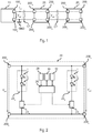
- Figure 5 shows a first embodiment of a lighting system including an electronic converter 10 and one or more lighting modules 20'.
- the system includes an electronic converter 10 as described with reference to Figure 1 , and the related description applies in its entirety also to the system of Figure 5 .
- the electronic converter 10 may include an AC/DC or DC/DC switched mode power supply, receiving at input a supply signal (e.g. from the mains) and providing at output, via a power output including a positive terminal 100a and a negative terminal 100b, representing a ground GND, a regulated voltage V out .
- FIG. 6 shows a possible embodiment of a lighting module 20' according to the present specification. Substantially, such a lighting module 20' has the same basic topology of the lighting module 20 described with reference to Figure 2 , and the related description also applies in its entirety to the lighting module 20' of Figure 6 (the differences will be described in detail in the following).
- lighting module 20' includes a positive input terminal 200a and a negative input terminal 200b, for connection to the terminals 100a and 100b of electronic converter 10. Therefore, the lighting module 20' receives, through terminals 200a and 200b, the voltage V out .
- lighting module 20' preferably includes a current regulator 24 connected in series with each LED string 22.
- the first LED string 22a and a first current regulator 24a are connected (e.g. directly) in series between the terminals 200a and 200b
- the second LED string 22b and a second current regulator 24b are connected (e.g. directly) in series between terminals 200a and 200b.
- strings 22a and 22b are powered by means of a common voltage ( V out ), and the LED strings 22 with the respective current regulators 24 included in the various lighting modules 20' should be connected in parallel with voltage V out provided by the electronic converter 10. As a consequence, in various embodiments the lighting modules 20' are electrically connected in parallel to voltage V out .
- the lighting module 20' may also include a positive output terminal 200c and a negative output terminal 200d, for the connection to a following lighting module, e.g. module 20' 2 .
- said terminals 200c/200d are internally connected (e.g. directly) to terminals 200a/200b. Therefore, voltage ( V out ) received at terminals 200a and 200b is also applied to terminals 200c and 200d. Therefore, terminals 200a and 200b of lighting module 20 2 may be connected (directly or via a cable) to terminals 200c and 200d of lighting module 20' 1 , which anyway provide the voltage V out . Consequently, although modules 20' 1 and 20' 2 are connected in series from a mechanical point of view, the electrical connection is in parallel.
- the lighting module 20' further includes a processing circuit 26 and optionally one or more sensors 28, actuators 30 and/or communication interfaces 32.
- a processing circuit 26 and optionally one or more sensors 28, actuators 30 and/or communication interfaces 32.
- the function of said modules 26, 28, 30 and 32 has already been described with reference to Figure 2 , and the related description also applies to Figure 6 in its entirety.
- processing circuit 26 and optionally the other components 28, 30 and 32 of lighting module 20' shown in Figure 6 may require a power supply which is not compatible with the voltage ( V out ) received via terminals 200a and 200b.
- each lighting module 20' includes (in addition to terminals 200a and 200b, and the optional terminals 200c and 200d) a further input terminal 200e, for receiving an auxiliary voltage V aux for powering the processing circuit 26 and optionally the other components 28, 30 and 32.
- said auxiliary voltage V aux may be connected to the supply pin of a microcontroller, which constitutes a processing circuit 26.
- each lighting module 20' may moreover include a further output terminal 200f which is internally connected (e.g. directly) to terminal 200e, so as to enable a connection to a following lighting module 20.
- the input terminal 200e of module 20 2 is connected to the output terminal 200f of module 20 1 .
- the electronic converter 10 does not provide the voltage V aux , but an additional device 40 is provided which is external with respect to the electronic converter 10 and the lighting module 20, wherein said additional device 40 is configured to receive voltage V out and generate voltage V aux , e.g. a voltage amounting to 3 VDC, 3.3 VDC or 5 VDC.
- said additional device 40 includes five connection terminals:
- device 40 should apply the voltage V out between the terminals 400c and 400d, and the voltage V aux between terminals 400e and 400d.
- terminal 400c is connected (e.g. directly) to terminal 400a within device 40, and similarly terminal 400d is connected (e.g. directly) to terminal 400b.
- the device includes an electronic converter 42, such as a voltage regulator configured to receive the voltage V out via terminals 400a and 400b and generate the voltage V aux which is applied to terminals 400e and 400b.
- the electronic converter 42 is a switched mode power supply, such as e.g. a buck converter.
- device 40 is interposed between the electronic converter 10 and the first lighting module 20 1 .
- a following lighting module 20 2 may be connected to terminals 200c, 200d and 200f of the lighting module 20 1 .
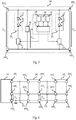
- Figures 7 and 8 show a second embodiment, wherein two distinct terminals are used for the negative terminals of the voltages V out and V aux .
- the lighting module may include a further (negative) input terminal 200g, and the voltage (V aux ) applied between the terminals 200e and 200g is used to supply the processing circuit and optionally the other components 28, 30 and 32. Also in this case, a further output terminal 200h may be provided, which is connected (e.g. directly) to terminal 200g, which may be used for the connection to a following lighting module.
- the lighting modules 20' include two terminals 200a and 200b for receiving a voltage V out for powering lighting sources L, and two terminals 200e and 200b for receiving a second voltage V aux for powering the processing circuit 26 and optionally the other components 28, 30 and 32.
- the positive terminals 200a and 200e are two distinct connection terminals, while negative terminal 200b/200g may also be in common.
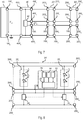
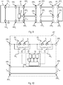
- the LEDs L distributed throughout the various lighting modules 20" are connected in series between terminals 100a and 100b.
- each lighting module 20" includes two terminals 200a and 200b.
- the LEDs L of said module are connected in series between terminals 200a and 200b.
- each lighting module further includes two terminals 200c and 200d for the connection to the terminals 200a and 200b of a following lighting module 20".
- the terminals 200c and 200d of the last lighting module 20 e.g. module 20" 2
- connection reference may be made to the Italian Patent Application TO2012A000028 , the content whereof is incorporated herein by way of reference.
- the LEDs L of each lighting module 20" may be connected in series between the terminals 200a and 200c (and/or between the terminals 200d and 200b, if a common ground is not used).
- each LED string 22 and/or each LED L may have means 24 associated thereto for regulating the current flowing through the LED string 22 and/or the LED L.
- such means 24 include an electronic switch which enables short-circuiting LED string 22 and/or LED L.
- said means 24 may be controlled via the processing circuit 26 described with reference to Figure 2 , e.g. for switching the LEDs off and/or for performing a dimming operation, e.g. by means of Pulse Width Modulation (PWM).
- PWM Pulse Width Modulation
- circuit 26 and optionally the other components, such as sensors 28, actuators 30 and/or communication interfaces 32, may require an additional supply voltage V aux .
- each lighting module 20" includes a terminal 200e for receiving said voltage V aux .
- Each lighting module 20" may further include a terminal 200f (internally connected to terminal 200e), which may be used for providing voltage V aux to a following lighting module 20".
- the system includes an additional device 40 generating the auxiliary voltage V aux, by diverting energy from the power supply lines (100a and 100b) used for powering the LEDs L included in the various lighting modules 20 (20' and 20") which are connected to the electronic converter 10 (10').
- the positive supply terminals i.e. terminals 100a, 200a, 200c, 400a and 400c
- the negative supply terminals i.e. terminals 100b, 200b, 200d, 400b and 400d
- the positive terminals used for the auxiliary voltage V aux i. e. terminals 200e, 200f and 400e
- Figure 11 shows an embodiment wherein the electronic converter 10, the device 40, the lighting module 20 1 and optionally one or more further lighting modules 20 2 are connected with each other via cables.
- the terminals 100a and 100b of the electronic converter 10 are implemented with rapid connection means, e.g. a screw or spring terminal block having e.g. two contacts.
- the electronic converter 10 further includes two terminals 100d and 100e for the connection to a power source, e.g. the mains or a battery.
- a power source e.g. the mains or a battery.
- these terminals 100d and 100e may be implemented via a terminal block.
- terminals 400a, 400b, 400c, 400d and 400e of device 40, and the terminals 200a, 420b, 200c, 200d, 200e and 200f of the lighting modules 20 (20' and 20") may be implemented with rapid connection means, e.g. screw or spring type terminal blocks having e.g. two or three contacts, as shown in the Figures.
- device 40 (specifically terminals 400a and 400b) is connected to the electronic converter 10 (specifically to terminals 100a and 100b) via a first electrical cable 50, having e.g. two wires.
- first lighting module 20 1 (specifically terminals 200a, 200b and 200e) is connected to device 40 (specifically to terminals 400c, 400d and 400e) via a second electrical cable 52, having e.g. three wires.
- a second lighting module 20 2 (specifically terminals 200a, 200b and 200e) may be connected to the first lighting module 20 1 (specifically to terminals 200c, 200d and 200f) via a third electrical cable 54, having e.g. three wires.
- the first cable 50 and/or the second cable 52 may also be soldered to device 40.
- the presently considered embodiment corresponds to the topology shown with reference to Figures 5 and 9 , and may therefore be used both for a voltage driving and for a current driving.
- the topology shown in Figure 7 having two distinct grounds, might be used.
- device 40 was always interposed between the electronic converter 10 and the first lighting module 20 1 .
- this is not mandatory, especially if the provided electronic converter 10 supplies a regulated voltage V out .
- the terminal 100a of electronic converter 10 and the terminals 200a and 200c of the lighting modules 20 have the same voltage V out .
- the terminals 200e and 200f of the lighting modules 20 have the same voltage V aux . Therefore, the device 40 may be arranged at any location.
- Figure 12 shows an embodiment wherein device 40 is connected to the last lighting module 20 2 .
- the first lighting module 20 1 (specifically terminals 200a and 200b) is connected to the electronic converter 10 (specifically to terminals 100a and 100b) via a first electrical cable 50, having e.g. two wires. Therefore, the terminal 200e of the first lighting module 20 1 is disconnected.
- a second lighting module 20 2 (specifically terminals 200a, 200b and 200e) may be connected to the first lighting module 20 1 (specifically to terminals 200c, 200d and 200f) via a second electrical cable 52, having e.g. three wires.
- device 40 (specifically terminals 400c, 400d and 400e) is connected to the last lighting module, e.g. lighting module 20 2 , (specifically to terminals 200c, 200d and 200f) via a third electrical cable 54, having e.g. three wires. Therefore, terminals 400a and 400b of device 40 are disconnected.
- Figure 13 shows a further embodiment, wherein device 40 is connected to the last lighting module 20 2 .
- the first lighting module 20 1 (specifically terminals 200a and 200b) is connected, as in Figure 12 , to the electronic converter 10 (specifically to terminals 100a and 100b) via a first electrical cable 50, having e.g. two wires. Therefore, the terminal 200e of the first lighting module 20 1 is disconnected.
- device 40 (specifically terminals 400c, 400d and 400e) is connected to the last lighting module, e.g. lighting module 20 2 , (specifically to terminals 200a, 200b and 200e) via a third electrical cable 54, having e.g. three wires. Therefore, terminals 400a and 400b of device 40 are disconnected.
- terminals 200c, 200d and 200f and terminals 200a, 200b and 200e of the lighting modules 20 may be inverted, because terminals 200c, 200d and 200f are internally connected to terminals 200a, 200b and 200e.
- cable 54 shown in Figures 12 and 13 may also be soldered to device 40.
- the terminal block which includes terminals 400a/400b and/or the terminal block which includes terminals 400c/400d/400e may be replaced with a connector having the same number of pins, i.e. two pins for terminals 400a/400b and three pins for terminals 400c/400d/400e. In this way, said pins may be inserted directly into the terminal block of the electronic converter 10 or of the lighting module 20.
- Figure 14 shows an embodiment of device 40 wherein terminals 400c/400d/400e are implemented by three pins.
- Figure 15 substantially shows the topology of Figure 11 , wherein the second cable 52 has been replaced with a direct connection between the pins of terminals 400c/400d/400e and the terminal block including terminals 200a/200b/200e of the first lighting module 20 1 .
- Figure 16 substantially shows the topology of Figure 12 , wherein the third cable 54 has been replaced with a direct connection between the pins of terminals 400c/400d/400e and the terminal block including terminals 200c/200d/200f of the last lighting module, e.g. module 20 2 .
- device 40 simply needs to be turned so that positive terminal 400c is connected to the positive terminal 200c of the lighting module.
- Figure 17 substantially shows the topology of Figure 13 , wherein the third cable 54 has been replaced with a direct connection between the pins of terminals 400c/400d/400e and the terminal block including terminals 200a/200d/200e of the last lighting module, e.g. module 20 2 .
- the electronic converter 42 of device 40 generating the auxiliary voltage V aux is external with respect to the electronic converter 10 and to the lighting modules 20. Therefore, these components may be developed independently, particularly as regards their magnetic interferences. For example, in this way the number of LEDs and the shape of the lighting modules 20 may easily be varied, because there is no need to design a new electronic converter (specifically a switched mode power supply) on the same printed circuit board of the lighting module 20 (e.g. converter 34 shown in Figure 3 ).
Landscapes
- Engineering & Computer Science (AREA)
- General Engineering & Computer Science (AREA)
- Microelectronics & Electronic Packaging (AREA)
- Circuit Arrangement For Electric Light Sources In General (AREA)
- Dc-Dc Converters (AREA)
Claims (13)
- Beleuchtungssystem umfassend:- einen elektronischen Wandler (10; 10') umfassend einen positiven (100a) und einen negativen (100b) Stromversorgungsanschluss zum Bereitstellen einer geregelten Spannung (Vout) oder eines geregelten Stroms (iout);- ein Beleuchtungsmodul (20'; 20"), umfassend:dadurch gekennzeichnet, dass das System umfasst:a) einen ersten positiven Anschluss (200a; 200c) und einen ersten negativen Anschluss (200b; 200d) zum Empfangen der geregelten Spannung (Vout) oder des geregelten Stroms (iout),b) mindestens eine Lichtquelle (L), die konfiguriert ist, um mittels der geregelten Spannung (Vout) oder dem geregelten Strom (iout) versorgt zu werden, die bzw. der über den ersten positiven Anschluss (200a; 200c) und den ersten negativen Anschluss (200b; 200d) des Beleuchtungsmoduls (20'; 20") empfangen wird,c) einen zweiten positiven Anschluss (200e; 200f) zum Empfangen einer Hilfsspannung (Vaux), undd) eine Verarbeitungsschaltung (26), die konfiguriert ist, um mittels der Hilfsspannung (Vaux) versorgt zu werden;- eine Vorrichtung (40), die in Bezug auf den elektronischen Wandler (10; 10') und das Beleuchtungsmodul (20'; 20") extern ist, wobei die Vorrichtung umfasst:a) einen ersten positiven Anschluss (400a; 400c) und einen ersten negativen Anschluss (400b; 400d) zum Empfangen der geregelten Spannung (Vout) oder des geregelten Stroms (iout),b) einen zweiten positiven Anschluss (400c; 400a), der mit dem ersten positiven Anschluss (400a; 400c) der Vorrichtung (40) verbunden ist, und einen zweiten negativen Anschluss (400d; 400b), der mit dem ersten negativen Anschluss (400b; 400d) der Vorrichtung (40) verbunden ist,c) einen dritten positiven Anschluss (400e), undd) einen Spannungsregler (42), der konfiguriert ist, um Energie von dem ersten positiven Anschluss (400a; 400c) und dem ersten negativen Anschluss (400b; 400d) der Vorrichtung (40) abzuleiten und die Hilfsspannung (Vaux) an dem dritten positiven Anschluss (400e) zu erzeugen.
- Beleuchtungssystem nach Anspruch 1, wobei:- das Beleuchtungsmodul (20'; 20") einen zweiten negativen Anschluss (200g; 200h) umfasst, und wobei die Verarbeitungsschaltung (26) konfiguriert ist, um mittels der Hilfsspannung (Vaux) versorgt zu werden, die zwischen dem zweiten positiven Anschluss (200e; 200f) und dem zweiten negativen Anschluss (200g; 200h) des Beleuchtungsmoduls (20'; 20") angelegt wird; und- die Vorrichtung (40) einen dritten negativen Anschluss (400f) umfasst, und wobei der Spannungsregler (42) konfiguriert ist, um die Hilfsspannung (Vaux) zwischen dem dritten positiven Anschluss (400e) und dem dritten negativen Anschluss (400f) der Vorrichtung (40) zu erzeugen.
- Beleuchtungssystem nach Anspruch 1, wobei:- die Verarbeitungsschaltung (26) konfiguriert ist, um mittels der Hilfsspannung (Vaux) versorgt zu werden, die zwischen dem zweiten positiven Anschluss (200e; 200f) und dem ersten negativen Anschluss (200b; 200d) des Beleuchtungsmoduls (20'; 20") angelegt wird; und- der Spannungsregler (42) konfiguriert ist, um die Hilfsspannung (Vaux) zwischen dem dritten positiven Anschluss (400e) und dem zweiten negativen Anschluss (400d; 400b) der Vorrichtung (40) zu erzeugen.
- Beleuchtungssystem nach irgendeinem der vorhergehenden Ansprüche, wobei der Spannungsregler (42) ein Schaltnetzteil, wie z.B. ein Abwärts-, Sperr- oder Durchflusswandler, ist.
- Beleuchtungssystem nach irgendeinem der vorhergehenden Ansprüche, wobei der Spannungsregler (42) konfiguriert ist, um eine Hilfsspannung (Vaux) mit 3 VDC, 3,3 VDC oder 5 VDC zu erzeugen.
- Beleuchtungssystem nach irgendeinem der vorhergehenden Ansprüche, wobei das Beleuchtungsmodul (20'; 20") einen dritten positiven Anschluss (200C; 200a), einen dritten negativen Anschluss (200d; 200b) und einen vierten positiven Anschluss (200f; 200e) umfasst, der mit dem zweiten positiven Anschluss (200e; 200f) des Beleuchtungsmoduls (20'; 20") verbunden ist.
- Beleuchtungssystem nach Anspruch 6, wobei:- der elektronische Wandler (10) eine geregelte Spannung (Vout) bereitstellt, wobei der dritte positive Anschluss (200c; 200a) mit dem ersten positiven Anschluss (200a; 200c) des Beleuchtungsmoduls (20'; 20") verbunden ist, der dritte negative Anschluss (200d; 200b) mit dem ersten negativen Anschluss (200b; 200d) des Beleuchtungsmoduls (20'; 20") verbunden ist, und wobei das Beleuchtungsmodul (20') mindestens eine LED-Kette (22) umfasst, die zwischen dem ersten positiven Anschluss (200a; 200c) und dem ersten negativen Anschluss (200b; 200d) des Beleuchtungsmoduls (20') verbunden ist; oder- der elektronische Wandler (10') einen geregelten Strom (iout) bereitstellt, und wobei das Beleuchtungsmodul (20') mindestens eine LED-Kette (22) umfasst, die zwischen dem ersten positiven Anschluss (200a; 200c) und dem dritten positiven Anschluss (200c; 200a) des Beleuchtungsmoduls (20') verbunden ist.
- Beleuchtungssystem nach Anspruch 7, wobei jede LED-Kette (22) ein zugehöriges Mittel (24) aufweist, das konfiguriert ist, um den durch die jeweilige LED-Kette (22) fließenden Strom zu regulieren, wobei die Verarbeitungsschaltung (26) konfiguriert ist, um den Betrieb des Mittels (24) zu steuern, das konfiguriert ist, um den durch die jeweilige LED-Kette (22) fließenden Strom zu regulieren.
- Beleuchtungssystem nach irgendeinem der vorhergehenden Ansprüche, wobei:- der erste positive Anschluss (400a; 400c) und der erste negative Anschluss (400b; 400d) der Vorrichtung (40) jeweils mit dem positiven Anschluss (100a) und dem negativen Anschluss (100b) des elektronischen Wandlers (10; 10') verbunden sind,- der zweite positive Anschluss (400c; 400a) und der zweite negative Anschluss (400d; 400b) der Vorrichtung (40) jeweils mit dem ersten positiven Anschluss (200a; 200c) und dem ersten negativen Anschluss (200b; 200d) des Beleuchtungsmoduls (20'; 20") verbunden sind, und- der dritte positive Anschluss (400e) der Vorrichtung (40) mit dem zweiten positiven Anschluss (200e; 200f) des Beleuchtungsmoduls (20'; 20") verbunden ist.
- Beleuchtungssystem nach irgendeinem der vorhergehenden Ansprüche 6 bis 8, wobei:- der erste positive Anschluss (200a; 200c) und der erste negative Anschluss (200b; 200d) des Beleuchtungsmoduls (20') jeweils mit dem positiven Anschluss (100a) und dem negativen Anschluss (100b) des elektronischen Wandlers (10) verbunden sind,- der zweite positive Anschluss (400c; 400a) und der zweite negative Anschluss (400d; 400b) der Vorrichtung (40) jeweils mit dem dritten positiven Anschluss (200c; 200a) und dem dritten negativen Anschluss (200d; 200b) des Beleuchtungsmoduls (20') verbunden sind, und- der dritte positive Anschluss (400e) der Vorrichtung (40) mit dem vierten positiven Anschluss (200f; 200e) des Beleuchtungsmoduls (20') verbunden ist.
- Beleuchtungssystem nach irgendeinem der vorhergehenden Ansprüche, wobei die Anschlüsse (100a, 100b) des elektronischen Wandlers (10; 10'), die Anschlüsse (200a, 200b, 200c, 200d, 200e, 200f) des Beleuchtungsmoduls (20'; 20") und die Anschlüsse (400a, 400b, 400c, 400d, 400e) der Vorrichtung (40) mit Schnellverbindungsmitteln, wie schraubartigen Anschlussblöcken oder federartigen Anschlussblöcken, implementiert sind, so dass der elektronische Wandler (10; 10'), das Beleuchtungsmodul (20'; 20") und die Vorrichtung (40) miteinander mittels Kabeln (50, 52, 54) verbunden werden können.
- Beleuchtungssystem nach irgendeinem der vorhergehenden Ansprüche, wobei ein erstes Kabel (52; 54) an den zweiten positiven Anschluss (400c), den zweiten negativen Anschluss (400d) und den dritten positiven Anschluss (400e) der Vorrichtung (40) gelötet ist und/oder ein zweites Kabel (50) an den ersten positiven Anschluss (400a) und den ersten negativen Anschluss (400b) gelötet ist.
- Beleuchtungssystem nach irgendeinem der vorhergehenden Ansprüche, wobei der zweite positive Anschluss (400c), der zweite negative Anschluss (400d) und der dritte positive Anschluss (400e) der Vorrichtung (40) und der erste positive Anschluss (200a; 200c), der erste negative Anschluss (200b; 200d) und der zweite positive Anschluss (200e; 200f) des Beleuchtungsmoduls (20'; 20") konfiguriert sind, um einen Verbinder zu implementieren, der eine direkte Verbindung zwischen dem zweiten positiven Anschluss (400c), dem zweiten negativen Anschluss (400d) und dem dritten positiven Anschluss (400e) der Vorrichtung (40) bzw. dem ersten positiven Anschluss (200a; 200c), dem ersten negativen Anschluss (200b; 200d) und dem zweiten positiven Anschluss (200e; 200f) des Beleuchtungsmoduls (20'; 20") ermöglicht.
Applications Claiming Priority (2)
| Application Number | Priority Date | Filing Date | Title |
|---|---|---|---|
| IT201600122187 | 2016-12-01 | ||
| PCT/IB2017/057483 WO2018100502A1 (en) | 2016-12-01 | 2017-11-29 | Lighting system |
Publications (2)
| Publication Number | Publication Date |
|---|---|
| EP3549403A1 EP3549403A1 (de) | 2019-10-09 |
| EP3549403B1 true EP3549403B1 (de) | 2020-08-05 |
Family
ID=58994991
Family Applications (1)
| Application Number | Title | Priority Date | Filing Date |
|---|---|---|---|
| EP17812083.8A Active EP3549403B1 (de) | 2016-12-01 | 2017-11-29 | Beleuchtungssystem |
Country Status (2)
| Country | Link |
|---|---|
| EP (1) | EP3549403B1 (de) |
| WO (1) | WO2018100502A1 (de) |
Families Citing this family (2)
| Publication number | Priority date | Publication date | Assignee | Title |
|---|---|---|---|---|
| CN111947055A (zh) * | 2020-09-22 | 2020-11-17 | 吴瑛香 | 一种灯珠及灯条 |
| EP4595702A1 (de) | 2022-09-30 | 2025-08-06 | Signify Holding B.V. | Led-modul zur bereitstellung von gleichmässigem licht |
Family Cites Families (2)
| Publication number | Priority date | Publication date | Assignee | Title |
|---|---|---|---|---|
| DE102010003799A1 (de) * | 2010-04-09 | 2011-12-15 | Tridonic Ag | Modulares LED-Beleuchtungssystem mit Notlichtfunktion |
| US8941311B2 (en) * | 2013-04-09 | 2015-01-27 | Bombardier Transportation Gmbh | Control of the intensity of a LED lighting system |
-
2017
- 2017-11-29 EP EP17812083.8A patent/EP3549403B1/de active Active
- 2017-11-29 WO PCT/IB2017/057483 patent/WO2018100502A1/en not_active Ceased
Non-Patent Citations (1)
| Title |
|---|
| None * |
Also Published As
| Publication number | Publication date |
|---|---|
| EP3549403A1 (de) | 2019-10-09 |
| WO2018100502A1 (en) | 2018-06-07 |
Similar Documents
| Publication | Publication Date | Title |
|---|---|---|
| US8779695B2 (en) | Method of configuring an LED driver, LED driver, LED assembly and method of controlling an LED assembly | |
| AU2017281321B2 (en) | Driver system for a light emitting device | |
| US10636290B2 (en) | Communication interface device for a solid-state luminaire | |
| US20120323394A1 (en) | Control System for Color Lights | |
| US10588193B2 (en) | LED module and lighting apparatus | |
| US9451673B2 (en) | Device for controlling a lighting device | |
| WO2019169014A1 (en) | Tapped single-stage buck converter led driver | |
| CN106688309B (zh) | Led调光器电路和方法 | |
| KR20100136571A (ko) | Led 구동 유닛 | |
| US9119255B2 (en) | Light source comprising a LED strip | |
| EP2862418A2 (de) | Selbstregulierende beleuchtungsansteuerung zur ansteuerung von lichtquellen und beleuchtungseinheit mit selbstregulierender beleuchtungsansteuerung | |
| US20140125242A1 (en) | Illumination system | |
| EP3603343B1 (de) | Ansteuerungsschaltung für duale led | |
| US10172198B2 (en) | Lighting system, related electronic converter and method of designing a lighting system | |
| US20160270175A1 (en) | Solid-state light-emitting element module and lighting assembly | |
| US9370060B2 (en) | Lighting device and illumination apparatus including same | |
| KR101901597B1 (ko) | 대기전력저감 및 잔광차단 기능이 구비된 조명등기구용 컨트롤러 및 이를 포함하는 조명등기구 | |
| EP3549403A1 (de) | Beleuchtungssystem | |
| US11234304B2 (en) | Photocontroller to control operation of a luminaire having a dimming line | |
| US9338842B2 (en) | Pulse switched resistor driver | |
| EP2503850B1 (de) | Beleuchtungshalterung | |
| US20180027618A9 (en) | Method And Apparatus For Modulating Load By Means Of A Control Command Obtained By Varying The Conduction Angle Of AC Voltage | |
| US9629223B2 (en) | Light-emitting device comprising two interfaces | |
| JP6886845B2 (ja) | 信号モジュール及び照明装置 | |
| EP3261414B1 (de) | Schutzschaltung für kurzschluss einer led-stromversorgung |
Legal Events
| Date | Code | Title | Description |
|---|---|---|---|
| STAA | Information on the status of an ep patent application or granted ep patent |
Free format text: STATUS: UNKNOWN |
|
| STAA | Information on the status of an ep patent application or granted ep patent |
Free format text: STATUS: THE INTERNATIONAL PUBLICATION HAS BEEN MADE |
|
| PUAI | Public reference made under article 153(3) epc to a published international application that has entered the european phase |
Free format text: ORIGINAL CODE: 0009012 |
|
| STAA | Information on the status of an ep patent application or granted ep patent |
Free format text: STATUS: REQUEST FOR EXAMINATION WAS MADE |
|
| 17P | Request for examination filed |
Effective date: 20190515 |
|
| AK | Designated contracting states |
Kind code of ref document: A1 Designated state(s): AL AT BE BG CH CY CZ DE DK EE ES FI FR GB GR HR HU IE IS IT LI LT LU LV MC MK MT NL NO PL PT RO RS SE SI SK SM TR |
|
| AX | Request for extension of the european patent |
Extension state: BA ME |
|
| DAV | Request for validation of the european patent (deleted) | ||
| DAX | Request for extension of the european patent (deleted) | ||
| GRAP | Despatch of communication of intention to grant a patent |
Free format text: ORIGINAL CODE: EPIDOSNIGR1 |
|
| STAA | Information on the status of an ep patent application or granted ep patent |
Free format text: STATUS: GRANT OF PATENT IS INTENDED |
|
| INTG | Intention to grant announced |
Effective date: 20200320 |
|
| GRAS | Grant fee paid |
Free format text: ORIGINAL CODE: EPIDOSNIGR3 |
|
| GRAA | (expected) grant |
Free format text: ORIGINAL CODE: 0009210 |
|
| STAA | Information on the status of an ep patent application or granted ep patent |
Free format text: STATUS: THE PATENT HAS BEEN GRANTED |
|
| AK | Designated contracting states |
Kind code of ref document: B1 Designated state(s): AL AT BE BG CH CY CZ DE DK EE ES FI FR GB GR HR HU IE IS IT LI LT LU LV MC MK MT NL NO PL PT RO RS SE SI SK SM TR |
|
| REG | Reference to a national code |
Ref country code: GB Ref legal event code: FG4D |
|
| REG | Reference to a national code |
Ref country code: CH Ref legal event code: EP |
|
| REG | Reference to a national code |
Ref country code: AT Ref legal event code: REF Ref document number: 1300558 Country of ref document: AT Kind code of ref document: T Effective date: 20200815 |
|
| REG | Reference to a national code |
Ref country code: DE Ref legal event code: R096 Ref document number: 602017021306 Country of ref document: DE |
|
| REG | Reference to a national code |
Ref country code: IE Ref legal event code: FG4D |
|
| RAP2 | Party data changed (patent owner data changed or rights of a patent transferred) |
Owner name: OSRAM GMBH Owner name: OSRAM S.P.A. - SOCIETA' RIUNITE OSRAM EDISON CLERICI |
|
| REG | Reference to a national code |
Ref country code: LT Ref legal event code: MG4D |
|
| REG | Reference to a national code |
Ref country code: NL Ref legal event code: MP Effective date: 20200805 |
|
| REG | Reference to a national code |
Ref country code: AT Ref legal event code: MK05 Ref document number: 1300558 Country of ref document: AT Kind code of ref document: T Effective date: 20200805 |
|
| PG25 | Lapsed in a contracting state [announced via postgrant information from national office to epo] |
Ref country code: FI Free format text: LAPSE BECAUSE OF FAILURE TO SUBMIT A TRANSLATION OF THE DESCRIPTION OR TO PAY THE FEE WITHIN THE PRESCRIBED TIME-LIMIT Effective date: 20200805 Ref country code: LT Free format text: LAPSE BECAUSE OF FAILURE TO SUBMIT A TRANSLATION OF THE DESCRIPTION OR TO PAY THE FEE WITHIN THE PRESCRIBED TIME-LIMIT Effective date: 20200805 Ref country code: BG Free format text: LAPSE BECAUSE OF FAILURE TO SUBMIT A TRANSLATION OF THE DESCRIPTION OR TO PAY THE FEE WITHIN THE PRESCRIBED TIME-LIMIT Effective date: 20201105 Ref country code: GR Free format text: LAPSE BECAUSE OF FAILURE TO SUBMIT A TRANSLATION OF THE DESCRIPTION OR TO PAY THE FEE WITHIN THE PRESCRIBED TIME-LIMIT Effective date: 20201106 Ref country code: NO Free format text: LAPSE BECAUSE OF FAILURE TO SUBMIT A TRANSLATION OF THE DESCRIPTION OR TO PAY THE FEE WITHIN THE PRESCRIBED TIME-LIMIT Effective date: 20201105 Ref country code: AT Free format text: LAPSE BECAUSE OF FAILURE TO SUBMIT A TRANSLATION OF THE DESCRIPTION OR TO PAY THE FEE WITHIN THE PRESCRIBED TIME-LIMIT Effective date: 20200805 Ref country code: ES Free format text: LAPSE BECAUSE OF FAILURE TO SUBMIT A TRANSLATION OF THE DESCRIPTION OR TO PAY THE FEE WITHIN THE PRESCRIBED TIME-LIMIT Effective date: 20200805 Ref country code: SE Free format text: LAPSE BECAUSE OF FAILURE TO SUBMIT A TRANSLATION OF THE DESCRIPTION OR TO PAY THE FEE WITHIN THE PRESCRIBED TIME-LIMIT Effective date: 20200805 Ref country code: HR Free format text: LAPSE BECAUSE OF FAILURE TO SUBMIT A TRANSLATION OF THE DESCRIPTION OR TO PAY THE FEE WITHIN THE PRESCRIBED TIME-LIMIT Effective date: 20200805 Ref country code: PT Free format text: LAPSE BECAUSE OF FAILURE TO SUBMIT A TRANSLATION OF THE DESCRIPTION OR TO PAY THE FEE WITHIN THE PRESCRIBED TIME-LIMIT Effective date: 20201207 |
|
| PG25 | Lapsed in a contracting state [announced via postgrant information from national office to epo] |
Ref country code: PL Free format text: LAPSE BECAUSE OF FAILURE TO SUBMIT A TRANSLATION OF THE DESCRIPTION OR TO PAY THE FEE WITHIN THE PRESCRIBED TIME-LIMIT Effective date: 20200805 Ref country code: RS Free format text: LAPSE BECAUSE OF FAILURE TO SUBMIT A TRANSLATION OF THE DESCRIPTION OR TO PAY THE FEE WITHIN THE PRESCRIBED TIME-LIMIT Effective date: 20200805 Ref country code: LV Free format text: LAPSE BECAUSE OF FAILURE TO SUBMIT A TRANSLATION OF THE DESCRIPTION OR TO PAY THE FEE WITHIN THE PRESCRIBED TIME-LIMIT Effective date: 20200805 Ref country code: NL Free format text: LAPSE BECAUSE OF FAILURE TO SUBMIT A TRANSLATION OF THE DESCRIPTION OR TO PAY THE FEE WITHIN THE PRESCRIBED TIME-LIMIT Effective date: 20200805 Ref country code: IS Free format text: LAPSE BECAUSE OF FAILURE TO SUBMIT A TRANSLATION OF THE DESCRIPTION OR TO PAY THE FEE WITHIN THE PRESCRIBED TIME-LIMIT Effective date: 20201205 |
|
| PG25 | Lapsed in a contracting state [announced via postgrant information from national office to epo] |
Ref country code: EE Free format text: LAPSE BECAUSE OF FAILURE TO SUBMIT A TRANSLATION OF THE DESCRIPTION OR TO PAY THE FEE WITHIN THE PRESCRIBED TIME-LIMIT Effective date: 20200805 Ref country code: DK Free format text: LAPSE BECAUSE OF FAILURE TO SUBMIT A TRANSLATION OF THE DESCRIPTION OR TO PAY THE FEE WITHIN THE PRESCRIBED TIME-LIMIT Effective date: 20200805 Ref country code: CZ Free format text: LAPSE BECAUSE OF FAILURE TO SUBMIT A TRANSLATION OF THE DESCRIPTION OR TO PAY THE FEE WITHIN THE PRESCRIBED TIME-LIMIT Effective date: 20200805 Ref country code: RO Free format text: LAPSE BECAUSE OF FAILURE TO SUBMIT A TRANSLATION OF THE DESCRIPTION OR TO PAY THE FEE WITHIN THE PRESCRIBED TIME-LIMIT Effective date: 20200805 Ref country code: SM Free format text: LAPSE BECAUSE OF FAILURE TO SUBMIT A TRANSLATION OF THE DESCRIPTION OR TO PAY THE FEE WITHIN THE PRESCRIBED TIME-LIMIT Effective date: 20200805 |
|
| REG | Reference to a national code |
Ref country code: DE Ref legal event code: R097 Ref document number: 602017021306 Country of ref document: DE |
|
| PG25 | Lapsed in a contracting state [announced via postgrant information from national office to epo] |
Ref country code: AL Free format text: LAPSE BECAUSE OF FAILURE TO SUBMIT A TRANSLATION OF THE DESCRIPTION OR TO PAY THE FEE WITHIN THE PRESCRIBED TIME-LIMIT Effective date: 20200805 |
|
| PLBE | No opposition filed within time limit |
Free format text: ORIGINAL CODE: 0009261 |
|
| STAA | Information on the status of an ep patent application or granted ep patent |
Free format text: STATUS: NO OPPOSITION FILED WITHIN TIME LIMIT |
|
| PG25 | Lapsed in a contracting state [announced via postgrant information from national office to epo] |
Ref country code: SK Free format text: LAPSE BECAUSE OF FAILURE TO SUBMIT A TRANSLATION OF THE DESCRIPTION OR TO PAY THE FEE WITHIN THE PRESCRIBED TIME-LIMIT Effective date: 20200805 Ref country code: MC Free format text: LAPSE BECAUSE OF FAILURE TO SUBMIT A TRANSLATION OF THE DESCRIPTION OR TO PAY THE FEE WITHIN THE PRESCRIBED TIME-LIMIT Effective date: 20200805 |
|
| REG | Reference to a national code |
Ref country code: CH Ref legal event code: PL |
|
| 26N | No opposition filed |
Effective date: 20210507 |
|
| PG25 | Lapsed in a contracting state [announced via postgrant information from national office to epo] |
Ref country code: IT Free format text: LAPSE BECAUSE OF FAILURE TO SUBMIT A TRANSLATION OF THE DESCRIPTION OR TO PAY THE FEE WITHIN THE PRESCRIBED TIME-LIMIT Effective date: 20200805 Ref country code: LU Free format text: LAPSE BECAUSE OF NON-PAYMENT OF DUE FEES Effective date: 20201129 |
|
| REG | Reference to a national code |
Ref country code: BE Ref legal event code: MM Effective date: 20201130 |
|
| PG25 | Lapsed in a contracting state [announced via postgrant information from national office to epo] |
Ref country code: CH Free format text: LAPSE BECAUSE OF NON-PAYMENT OF DUE FEES Effective date: 20201130 Ref country code: LI Free format text: LAPSE BECAUSE OF NON-PAYMENT OF DUE FEES Effective date: 20201130 Ref country code: SI Free format text: LAPSE BECAUSE OF FAILURE TO SUBMIT A TRANSLATION OF THE DESCRIPTION OR TO PAY THE FEE WITHIN THE PRESCRIBED TIME-LIMIT Effective date: 20200805 |
|
| REG | Reference to a national code |
Ref country code: IE Ref legal event code: MM4A |
|
| PG25 | Lapsed in a contracting state [announced via postgrant information from national office to epo] |
Ref country code: IE Free format text: LAPSE BECAUSE OF NON-PAYMENT OF DUE FEES Effective date: 20201129 Ref country code: FR Free format text: LAPSE BECAUSE OF NON-PAYMENT OF DUE FEES Effective date: 20201130 |
|
| REG | Reference to a national code |
Ref country code: DE Ref legal event code: R079 Ref document number: 602017021306 Country of ref document: DE Free format text: PREVIOUS MAIN CLASS: H05B0033080000 Ipc: H05B0044000000 |
|
| PG25 | Lapsed in a contracting state [announced via postgrant information from national office to epo] |
Ref country code: TR Free format text: LAPSE BECAUSE OF FAILURE TO SUBMIT A TRANSLATION OF THE DESCRIPTION OR TO PAY THE FEE WITHIN THE PRESCRIBED TIME-LIMIT Effective date: 20200805 Ref country code: MT Free format text: LAPSE BECAUSE OF FAILURE TO SUBMIT A TRANSLATION OF THE DESCRIPTION OR TO PAY THE FEE WITHIN THE PRESCRIBED TIME-LIMIT Effective date: 20200805 Ref country code: CY Free format text: LAPSE BECAUSE OF FAILURE TO SUBMIT A TRANSLATION OF THE DESCRIPTION OR TO PAY THE FEE WITHIN THE PRESCRIBED TIME-LIMIT Effective date: 20200805 |
|
| PG25 | Lapsed in a contracting state [announced via postgrant information from national office to epo] |
Ref country code: MK Free format text: LAPSE BECAUSE OF FAILURE TO SUBMIT A TRANSLATION OF THE DESCRIPTION OR TO PAY THE FEE WITHIN THE PRESCRIBED TIME-LIMIT Effective date: 20200805 |
|
| GBPC | Gb: european patent ceased through non-payment of renewal fee |
Effective date: 20211129 |
|
| PG25 | Lapsed in a contracting state [announced via postgrant information from national office to epo] |
Ref country code: BE Free format text: LAPSE BECAUSE OF NON-PAYMENT OF DUE FEES Effective date: 20201130 |
|
| PG25 | Lapsed in a contracting state [announced via postgrant information from national office to epo] |
Ref country code: GB Free format text: LAPSE BECAUSE OF NON-PAYMENT OF DUE FEES Effective date: 20211129 |
|
| REG | Reference to a national code |
Ref country code: DE Ref legal event code: R081 Ref document number: 602017021306 Country of ref document: DE Owner name: OPTOTRONIC GMBH, DE Free format text: FORMER OWNER: OSRAM GMBH, 80807 MUENCHEN, DE Ref country code: DE Ref legal event code: R081 Ref document number: 602017021306 Country of ref document: DE Owner name: INVENTRONICS GMBH, DE Free format text: FORMER OWNER: OSRAM GMBH, 80807 MUENCHEN, DE |
|
| REG | Reference to a national code |
Ref country code: DE Ref legal event code: R081 Ref document number: 602017021306 Country of ref document: DE Owner name: INVENTRONICS GMBH, DE Free format text: FORMER OWNER: OPTOTRONIC GMBH, 85748 GARCHING, DE |
|
| PGFP | Annual fee paid to national office [announced via postgrant information from national office to epo] |
Ref country code: DE Payment date: 20251118 Year of fee payment: 9 |