EP3549327B1 - Transmission system for monitoring equipment in rat traps positioned in sewers, shafts, and wells - Google Patents
Transmission system for monitoring equipment in rat traps positioned in sewers, shafts, and wells Download PDFInfo
- Publication number
- EP3549327B1 EP3549327B1 EP17797624.8A EP17797624A EP3549327B1 EP 3549327 B1 EP3549327 B1 EP 3549327B1 EP 17797624 A EP17797624 A EP 17797624A EP 3549327 B1 EP3549327 B1 EP 3549327B1
- Authority
- EP
- European Patent Office
- Prior art keywords
- transmission system
- monitoring data
- wireless
- well
- monitoring equipment
- Prior art date
- Legal status (The legal status is an assumption and is not a legal conclusion. Google has not performed a legal analysis and makes no representation as to the accuracy of the status listed.)
- Revoked
Links
Images
Classifications
-
- H—ELECTRICITY
- H04—ELECTRIC COMMUNICATION TECHNIQUE
- H04L—TRANSMISSION OF DIGITAL INFORMATION, e.g. TELEGRAPHIC COMMUNICATION
- H04L67/00—Network arrangements or protocols for supporting network services or applications
- H04L67/01—Protocols
- H04L67/12—Protocols specially adapted for proprietary or special-purpose networking environments, e.g. medical networks, sensor networks, networks in vehicles or remote metering networks
Definitions
- the present invention relates to monitoring equipment in rat traps for positioning in sewers, shafts, and wells.
- a first aspect relates to a wireless transmission system for monitoring equipment in rat traps positioned in sewers, shafts and wells comprising:
- a second aspect relates to a wireless transmission system for monitoring equipment in rat traps positioned in sewers, shafts and wells comprising:
- the term “repeater” means a system that receives, amplifies, and re-transmits a wireless signal without extracting the user information or converting the communications protocol.
- the term “relay” refers to a system that receives, decodes, data regenerates, data transmits, encodes, amplifies, and re-transmits a wireless signal.
- monitoring means or “monitoring equipment” should be understood very broadly in this context. However, some monitoring means or monitoring equipment are given preference, such as sensors, and flowmeters, e.g. a rat kill monitoring means e.g. embodied as a shock sensor, or a motion sensor.
- a rat kill monitoring means e.g. embodied as a shock sensor, or a motion sensor.
- the transmission system comprises positioning means adapted for positioning and/or attaching the wireless repeater or wireless relay 5-100 cm below the well or shaft cover, such as within the range of 10-95 cm, e.g. within the range of 15-90 cm, such as within the range of 20-85 cm, e.g. within the range of 25-80 cm, such as within the range of 30-75 cm, e.g. within the range of 35-70 cm, such as within the range of 40-65 cm, e.g. within the range of 45-60 cm.
- This position is important to avoid shielding from the well or shaft cover that is often made of metal.
- the surrounding soil layer around the well or shaft must not be too thick in order for the emitted signal to pass through.
- the transmission system cannot work without the wireless repeater or wireless relay, as the emitted signal from the transmitter unit, positioned in close relation to the monitoring equipment within the sewer or on the bottom of the well or shaft, cannot penetrate the surrounding soil layer around the well or shaft; and the well or shaft cover will block the remaining signal.
- the transmission system comprises a receiver unit adapted for being positioned and/or attached within a range of 0-100 meters from the well or shaft cover, such as within the range of 1-95 meters, e.g. within the range of 2-90 meters, such as within the range of 3-85 meters, e.g. within the range of 4-80 meters, such as within the range of 5-85 meters, e.g. within the range of 10-70 meters, such as within the range of 15-65 meters, e.g. within the range of 20-60 meters, such as within the range of 25-55 meters, e.g. within the range of 30-50 meters, such as within the range of 35-45 meters.
- a receiver unit adapted for being positioned and/or attached within a range of 0-100 meters from the well or shaft cover, such as within the range of 1-95 meters, e.g. within the range of 2-90 meters, such as within the range of 3-85 meters, e.g. within the range of 4-80 meters, such as within the range of 5-85 meters, e.g
- the receiver unit should be configured to receive the signal from the wireless repeater or wireless relay at a distance from the well cover.
- the battery life of the repeater or wireless relay is as long as possible to reduce underground service.
- the receiver unit should be positioned as close as possible to the well cover to avoid spending too much energy on transmission from the repeater or wireless relay. This leads to an overall energy reduction of the entire system, which increases the battery life of all components.
- the positioning means comprises an extendable rod with means provided for locking said extendable rod in a determined length; wherein the extendable rod further comprises means arranged in both ends of for engaging the side wall of a well.
- the transmitter unit is configured for transmitting with a wavelength and frequency that cannot penetrate the water when the transmitter is positioned under water, such as under 10-100 cm of water.
- the transmitter unit is configured for transmitting with a wavelength and frequency that is at least partly absorbed in water or in water comprising conducting contaminants, such as salts, and wherein the wireless repeater and/or the receiver unit are configured for measuring the time period between received monitoring data signals.
- the time period will give an indirect indication on whether the well or shaft is flooded. When flooded, the signal is unable to pass through the water or the contaminated water, as it is poorly conducting, and furthermore may reflect the signal.
- the wireless repeater and/or the receiver unit are configured for logging an alarm and/or creating and transmitting an alarm signal. This is important, as a time period exceeding e.g. 20 minutes is an indication of a blockage of the sewer, which will cause sewage water to rise and escape the sewage system through any possible opening, such as into e.g. a basement of a household.
- the transmission system is particularly useful for rodent traps (especially rat traps), as there is no system available for continuous wireless communication with a trap mounted within a well and sewer system. Cables are not suitable for drawing through the well opening and across a road, for obvious reasons; and the rats will gnaw on the cables. Therefore, some traps are connected via cables to a control box positioned right below the well cover.
- the control box comprises a GSM module configured for transmitting monitoring data.
- this setup does not provide a stabile communication to a receiver, as the GSM signal is blocked by the cover and the surrounding soil layer around the well.
- the monitoring equipment is embedded in a rat trap. Such equipment may monitor the release of the trap, or the presence of a rat in or near the trap. If the killing means in the trap is released by use of pressurized gas, such as carbon dioxide, the monitoring equipment may be a shock sensor, such as a G-sensor.
- the transmitter unit is embedded in a rat trap. This configuration will avoid external cabling.
- the receiver unit is configured for transmitting the received monitoring data and potential alarm signals to a server at a network location.
- This configuration will allow for a continuous connection with the monitoring equipment.
- the signal may be transmitted by e.g. satellite, 4G, 3G, 5G, radio link, GSM, LTE, and/or UMTS.
- a third aspect relates to the use of a transmission system according to the present invention for rodent control in sewers or shafts, wherein the wireless repeater or wireless relay is positioned 5-100 cm below a) the well cover of a well in fluid communication with a sewer or b) the shaft cover, and wherein the receiver unit is positioned on the ground within a range of 0-100 meters from said well cover or shaft cover.
- the monitoring data comprises information about the activity of the killing means of a rat trap.
- the monitoring data comprises information about the presence of rats within the sewer, well or shaft.
- the wireless repeater and/or the wireless relay and/or the transmitter unit and/or the receiver unit are configured to emit an ON/OFF synchronizing signal. Synchronization of the different units reduces the energy consumption, and the battery within the different units will last longer. This is important, as the service frequency of the individual units is thereby also reduced.
- the wireless repeater and/or the wireless relay is configured to ON/OFF synchronize with the transmitter unit.
- the transmitter unit is configured to ON/OFF synchronize with the wireless repeater and/or the wireless relay.
- the wireless repeater and/or the wireless relay is configured to ON/OFF synchronize with the transmitter unit; and the transmitter unit is configured to ON/OFF synchronize with the wireless repeater and/or the wireless relay.
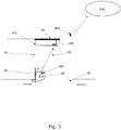
- Figure 1 shows a transmission system for monitoring equipment 10 embedded in a rat trap 30.
- the transmission system comprises a transmitter unit 100, a wireless repeater or wireless relay 200, positioning means 300, and a receiver unit 400.
- the transmitter unit 100 is configured for receiving monitoring data from a monitoring equipment 10 embedded in a rat trap 30, and for transmitting the received monitoring data.
- the wireless repeater or wireless relay 200 is configured for receiving the monitoring data from the monitoring equipment 10.
- the positioning means 300 is adapted for positioning the wireless repeater or wireless relay 200 at a position below the well cover 20, preferably 5-100 cm below the well cover 20.
- the receiver unit 400 is adapted for being positioned within a range of 0-100 meters from the well or shaft cover 20, and configured for receiving a monitoring data signal from a monitoring equipment 10 repeated by the wireless repeater and/or the wireless relay 200.
- the receiver unit 400 is also configured for transmitting the received monitoring data to a server 500 at a network location.
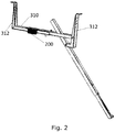
- FIG 2 shows the positioning means 300 in accordance with various embodiments of the invention.
- the positioning means 300 comprises an extendable rod 310 with means provided for locking said extendable rod 310 in a determined length. Furthermore, means 312 are arranged in both ends of the extendable rod 310 for engaging the side wall of a well.
- the positioning means 300 are also adapted as anchoring means for anchoring the rat trap 30 with a wire 32 ( Figure 1 ).
Landscapes
- Engineering & Computer Science (AREA)
- Health & Medical Sciences (AREA)
- Computing Systems (AREA)
- General Health & Medical Sciences (AREA)
- Medical Informatics (AREA)
- Computer Networks & Wireless Communication (AREA)
- Signal Processing (AREA)
- Arrangements For Transmission Of Measured Signals (AREA)
Description
- The present invention relates to monitoring equipment in rat traps for positioning in sewers, shafts, and wells.
- Today, monitoring means, such as sensors, are positioned in rat traps for use in sewers and shafts to measure many different conditions. Signals produced by a sensor are relayed above the ground to a sensor monitoring and control unit via cables. However, such a communication system is time consuming to install, and the cables are susceptible to the sometimes very hostile environment within the sewer or shaft. To avoid the latter, very expensive cables are used. However, rodents present in sewers and shafts tend to gnaw in cables, thereby ruining the communication path. Furthermore, the cables are not suitable for drawing through the well or shaft opening and across a road, for obvious reasons. Document
US2014300477 A1 discloses a remote notification electronic rodent trapping system having a plurality of electronic rodent trapping devices configured to wirelessly communicate trap information to each other and to a PC or wireless device. - It is therefore desirable to provide a transmission system that avoids or at least alleviates the above-mentioned problems.
- A first aspect relates to a wireless transmission system for monitoring equipment in rat traps positioned in sewers, shafts and wells comprising:
- a transmitter unit embedded in a rat trap, and configured for receiving monitoring data from a monitoring equipment embedded within said rat trap, and for transmitting the received monitoring data;
- a wireless repeater or a wireless relay configured for receiving the monitoring data from said monitoring equipment; and
- a receiver unit adapted for being positioned within a range of 0-100 meters from the well or shaft cover, and configured for receiving a monitoring data signal from a monitoring equipment repeated by the wireless repeater and/or the wireless relay.
- A second aspect relates to a wireless transmission system for monitoring equipment in rat traps positioned in sewers, shafts and wells comprising:
- a transmitter unit embedded in a rat trap, and configured for receiving monitoring data from a monitoring equipment embedded within said rat trap, and for transmitting the received monitoring data;
- a wireless repeater or a wireless relay configured for receiving the monitoring data from said monitoring equipment;
- positioning means adapted for positioning and/or attaching the wireless repeater or wireless relay 5-100 cm below the well or shaft cover; and
- a receiver unit adapted for being positioned within a range of 0-100 meters from the well or shaft cover, and configured for receiving a monitoring data signal from a monitoring equipment repeated by the wireless repeater and/or the wireless relay.
- In the present context, the term "repeater" means a system that receives, amplifies, and re-transmits a wireless signal without extracting the user information or converting the communications protocol. The term "relay" refers to a system that receives, decodes, data regenerates, data transmits, encodes, amplifies, and re-transmits a wireless signal.
- The terms "monitoring means" or "monitoring equipment" should be understood very broadly in this context. However, some monitoring means or monitoring equipment are given preference, such as sensors, and flowmeters, e.g. a rat kill monitoring means e.g. embodied as a shock sensor, or a motion sensor.
- In one or more embodiments, the transmission system comprises positioning means adapted for positioning and/or attaching the wireless repeater or wireless relay 5-100 cm below the well or shaft cover, such as within the range of 10-95 cm, e.g. within the range of 15-90 cm, such as within the range of 20-85 cm, e.g. within the range of 25-80 cm, such as within the range of 30-75 cm, e.g. within the range of 35-70 cm, such as within the range of 40-65 cm, e.g. within the range of 45-60 cm. This position is important to avoid shielding from the well or shaft cover that is often made of metal. Furthermore, the surrounding soil layer around the well or shaft must not be too thick in order for the emitted signal to pass through. This is why the transmission system cannot work without the wireless repeater or wireless relay, as the emitted signal from the transmitter unit, positioned in close relation to the monitoring equipment within the sewer or on the bottom of the well or shaft, cannot penetrate the surrounding soil layer around the well or shaft; and the well or shaft cover will block the remaining signal.
- In one or more embodiments, the transmission system comprises a receiver unit adapted for being positioned and/or attached within a range of 0-100 meters from the well or shaft cover, such as within the range of 1-95 meters, e.g. within the range of 2-90 meters, such as within the range of 3-85 meters, e.g. within the range of 4-80 meters, such as within the range of 5-85 meters, e.g. within the range of 10-70 meters, such as within the range of 15-65 meters, e.g. within the range of 20-60 meters, such as within the range of 25-55 meters, e.g. within the range of 30-50 meters, such as within the range of 35-45 meters. Often the well is positioned below a road, and hence, the receiver unit cannot be blocking the road. Thus, the receiver unit should be configured to receive the signal from the wireless repeater or wireless relay at a distance from the well cover. On the other hand, it is preferred that the battery life of the repeater or wireless relay is as long as possible to reduce underground service. Hence, the receiver unit should be positioned as close as possible to the well cover to avoid spending too much energy on transmission from the repeater or wireless relay. This leads to an overall energy reduction of the entire system, which increases the battery life of all components.
- In one or more embodiments, the positioning means comprises an extendable rod with means provided for locking said extendable rod in a determined length; wherein the extendable rod further comprises means arranged in both ends of for engaging the side wall of a well.
- In one or more embodiments, the transmitter unit is configured for transmitting with a wavelength and frequency that cannot penetrate the water when the transmitter is positioned under water, such as under 10-100 cm of water.
- In one or more embodiments, the transmitter unit is configured for transmitting with a wavelength and frequency that is at least partly absorbed in water or in water comprising conducting contaminants, such as salts, and wherein the wireless repeater and/or the receiver unit are configured for measuring the time period between received monitoring data signals. The time period will give an indirect indication on whether the well or shaft is flooded. When flooded, the signal is unable to pass through the water or the contaminated water, as it is poorly conducting, and furthermore may reflect the signal.
- In one or more embodiments, wherein when the time period between received monitoring data signals exceeds a predetermined threshold, the wireless repeater and/or the receiver unit are configured for logging an alarm and/or creating and transmitting an alarm signal. This is important, as a time period exceeding e.g. 20 minutes is an indication of a blockage of the sewer, which will cause sewage water to rise and escape the sewage system through any possible opening, such as into e.g. a basement of a household.
- The transmission system is particularly useful for rodent traps (especially rat traps), as there is no system available for continuous wireless communication with a trap mounted within a well and sewer system. Cables are not suitable for drawing through the well opening and across a road, for obvious reasons; and the rats will gnaw on the cables. Therefore, some traps are connected via cables to a control box positioned right below the well cover. The control box comprises a GSM module configured for transmitting monitoring data. However, this setup does not provide a stabile communication to a receiver, as the GSM signal is blocked by the cover and the surrounding soil layer around the well.
- The monitoring equipment is embedded in a rat trap. Such equipment may monitor the release of the trap, or the presence of a rat in or near the trap. If the killing means in the trap is released by use of pressurized gas, such as carbon dioxide, the monitoring equipment may be a shock sensor, such as a G-sensor.
- The transmitter unit is embedded in a rat trap. This configuration will avoid external cabling.
- In one or more embodiments, the receiver unit is configured for transmitting the received monitoring data and potential alarm signals to a server at a network location. This configuration will allow for a continuous connection with the monitoring equipment. The signal may be transmitted by e.g. satellite, 4G, 3G, 5G, radio link, GSM, LTE, and/or UMTS.
- A third aspect relates to the use of a transmission system according to the present invention for rodent control in sewers or shafts, wherein the wireless repeater or wireless relay is positioned 5-100 cm below a) the well cover of a well in fluid communication with a sewer or b) the shaft cover, and wherein the receiver unit is positioned on the ground within a range of 0-100 meters from said well cover or shaft cover.
- In one or more embodiments, the monitoring data comprises information about the activity of the killing means of a rat trap.
- In one or more embodiments, the monitoring data comprises information about the presence of rats within the sewer, well or shaft.
- In one or more embodiments, the wireless repeater and/or the wireless relay and/or the transmitter unit and/or the receiver unit are configured to emit an ON/OFF synchronizing signal. Synchronization of the different units reduces the energy consumption, and the battery within the different units will last longer. This is important, as the service frequency of the individual units is thereby also reduced.
- In one or more embodiments, the wireless repeater and/or the wireless relay is configured to ON/OFF synchronize with the transmitter unit.
- In one or more embodiments, the transmitter unit is configured to ON/OFF synchronize with the wireless repeater and/or the wireless relay.
- In one or more embodiments, the wireless repeater and/or the wireless relay is configured to ON/OFF synchronize with the transmitter unit; and the transmitter unit is configured to ON/OFF synchronize with the wireless repeater and/or the wireless relay.
- It should be noted that embodiments and features described in the context of one of the aspects of the present invention also apply to the other aspects of the invention, as defined by the appended claims.
-
-
Figure 1 shows a transmission system in accordance with various embodiments of the invention; and -
Figure 2 shows the positioning means in accordance with various embodiments of the invention. - Referring to
Figure 1 , the general scheme of the invention is shown.Figure 1 shows a transmission system for monitoringequipment 10 embedded in arat trap 30. The transmission system comprises atransmitter unit 100, a wireless repeater orwireless relay 200, positioning means 300, and areceiver unit 400. Thetransmitter unit 100 is configured for receiving monitoring data from amonitoring equipment 10 embedded in arat trap 30, and for transmitting the received monitoring data. The wireless repeater orwireless relay 200 is configured for receiving the monitoring data from themonitoring equipment 10. The positioning means 300 is adapted for positioning the wireless repeater orwireless relay 200 at a position below thewell cover 20, preferably 5-100 cm below thewell cover 20. Thereceiver unit 400 is adapted for being positioned within a range of 0-100 meters from the well orshaft cover 20, and configured for receiving a monitoring data signal from amonitoring equipment 10 repeated by the wireless repeater and/or thewireless relay 200. Thereceiver unit 400 is also configured for transmitting the received monitoring data to aserver 500 at a network location. -
Figure 2 shows the positioning means 300 in accordance with various embodiments of the invention. The positioning means 300 comprises anextendable rod 310 with means provided for locking saidextendable rod 310 in a determined length. Furthermore, means 312 are arranged in both ends of theextendable rod 310 for engaging the side wall of a well. The positioning means 300 are also adapted as anchoring means for anchoring therat trap 30 with a wire 32 (Figure 1 ). -
- 10
- Monitoring equipment
- 20
- Well cover
- 30
- Rat trap
- 32
- Wire
- 40
- Well
- 50
- Sewer
- 100
- Transmitter unit
- 200
- Wireless repeater or wireless relay
- 300
- Positioning means
- 310
- Extendable rod
- 312
- Means for engaging the side wall of a well or shaft
- 400
- Receiver unit
- 500
- Server
Claims (10)
- A wireless transmission system for monitoring equipment in rat traps positioned in sewers, shafts and wells comprising:- a transmitter unit (100) embedded in a rat trap (30), and configured for receiving monitoring data from a monitoring equipment (10) embedded within said rat trap (30), and for wirelessly transmitting the received monitoring data; and- a receiver unit (400) adapted for being positioned within a range of 0-100 meters from the well or shaft cover (20), and configured for receiving a monitoring data signal from a monitoring equipment (10); the wireless transmission system further comprises:- a wireless repeater or wireless relay (200) configured for wirelessly receiving the monitoring data from said monitoring equipment (10) via said transmitter unit (100); and- positioning means (300) adapted for positioning and/or attaching the wireless repeater or wireless relay (200) 5-100 cm below the well or shaft cover (20); wherein said receiver unit (400) is configured for receiving a monitoring data signal from said monitoring equipment (10) via said wireless repeater and/or said wireless relay (200).
- A transmission system according to claim 1, wherein the positioning means (300) comprises an extendable rod (310) with means provided for locking said extendable rod in a determined length; wherein the extendable rod further comprises means (312) arranged in both ends of for engaging the side wall of a well or shaft.
- A transmission system according to any one of the claims 1-2, wherein the transmitter unit (100) is configured for transmitting with a wavelength and frequency that a) is at least partly absorbed or reflected in water and/or b) is at least partly absorbed or reflected in water comprising conducting contaminants and/or c) that cannot pass through 10-100 cm of water or water comprising conducting contaminants; and wherein the wireless repeater or wireless relay (200) and/or the receiver unit (400) are configured for measuring the time period between received monitoring data signals.
- A transmission system according to claim 3; wherein when the time period between received monitoring data signals exceeds a predetermined threshold, the wireless repeater or wireless relay (200) and/or the receiver unit (400) are configured for logging an alarm and/or creating and transmitting an alarm signal.
- A transmission system according to any one of the claims 1-4, wherein the monitoring equipment (10) is a rat kill monitoring means, such a shock sensor, or a motion sensor.
- A transmission system according to any one of the claims 1-5, wherein the killing means in the trap is released by use of pressurized gas, such as carbon dioxide.
- A transmission system according to any one of the claims 1-6, wherein the receiver unit (400) is configured for transmitting the received monitoring data and potential alarm signals to a server (500) at a network location.
- Use of a transmission system according to any one of the claims 1-7 for rodent control in sewers or shafts, wherein the wireless repeater or wireless relay (200) is positioned 5-100 cm below a) the well cover (20) of a well in fluid communication with a sewer or b) the shaft cover, and wherein the receiver unit is positioned on the ground within a range of 0-100 meters from said well cover (20) or shaft cover.
- Use according to claim 8, wherein the monitoring data comprises information about the activity of the killing means of a rat trap.
- Use according to any one of the claims 8-9, wherein the monitoring data comprises information about the presence of rats within the sewer, well or shaft.
Applications Claiming Priority (3)
| Application Number | Priority Date | Filing Date | Title |
|---|---|---|---|
| DKPA201670956 | 2016-12-01 | ||
| DKBA201600138U DK201600138U4 (en) | 2016-12-01 | 2016-12-01 | Transmission system for rat traps monitoring equipment located in sewers, shafts and wells |
| PCT/EP2017/078824 WO2018099707A1 (en) | 2016-12-01 | 2017-11-09 | Transmission system for monitoring equipment in rat traps positioned in sewers, shafts, and wells |
Publications (2)
| Publication Number | Publication Date |
|---|---|
| EP3549327A1 EP3549327A1 (en) | 2019-10-09 |
| EP3549327B1 true EP3549327B1 (en) | 2022-01-05 |
Family
ID=60320882
Family Applications (1)
| Application Number | Title | Priority Date | Filing Date |
|---|---|---|---|
| EP17797624.8A Revoked EP3549327B1 (en) | 2016-12-01 | 2017-11-09 | Transmission system for monitoring equipment in rat traps positioned in sewers, shafts, and wells |
Country Status (3)
| Country | Link |
|---|---|
| EP (1) | EP3549327B1 (en) |
| DK (1) | DK3549327T3 (en) |
| WO (1) | WO2018099707A1 (en) |
Cited By (3)
| Publication number | Priority date | Publication date | Assignee | Title |
|---|---|---|---|---|
| WO2020094530A1 (en) | 2018-11-08 | 2020-05-14 | Ratél Aps | Transmission system for monitoring equipment in rat traps positioned in sewers, shafts, and wells |
| WO2023170219A1 (en) * | 2022-03-10 | 2023-09-14 | Anticimex Innovation Center A/S | A system for monitoring rodents in a sewage system, a monitoring device and methods related there to |
| DE102024117468A1 (en) * | 2024-06-20 | 2025-12-24 | Rattex Schädlingsbekämpfung Gmbh | Pest monitoring system |
Families Citing this family (1)
| Publication number | Priority date | Publication date | Assignee | Title |
|---|---|---|---|---|
| CN113706818A (en) * | 2021-07-08 | 2021-11-26 | 上海建工集团股份有限公司 | Prevent intelligent well lid system of falling from reporting to police |
Citations (15)
| Publication number | Priority date | Publication date | Assignee | Title |
|---|---|---|---|---|
| US5583492A (en) | 1993-09-24 | 1996-12-10 | Hitachi Cable, Ltd. | Method and apparatus for monitoring inside a manhole |
| US20010011009A1 (en) | 1996-04-22 | 2001-08-02 | Toshio Harada | Underground information communication system and related manhole cover |
| US6378817B1 (en) | 2000-05-05 | 2002-04-30 | Badger Meter, Inc. | Kit and method for mounting a transmitter in subsurface meter pits |
| US20040196159A1 (en) | 2003-04-02 | 2004-10-07 | Vintage Water Works Supply Corp. | Bracket system and method for use with remote-reading water meters |
| US20050285807A1 (en) | 2004-06-25 | 2005-12-29 | Ilan Zehngut | RF communication device and method of using it and antenna construction for use in the device and method |
| WO2007026123A1 (en) | 2005-09-03 | 2007-03-08 | Riwa Limited | A pest monitoring system |
| US20070103324A1 (en) | 2002-03-05 | 2007-05-10 | Aeromesh Corporation | Monitoring system and method |
| US20080106434A1 (en) | 2006-10-18 | 2008-05-08 | Arad Measuring Technologies Ltd. | Data collection system and method for collecting utility consumption data |
| EP2187174A1 (en) | 2008-11-14 | 2010-05-19 | Kamstrup A/S | Communication device arranged for wireless communication with a consumption meter |
| NZ575339A (en) | 2010-03-03 | 2011-08-26 | Goodnature Ltd | A Gas Powered Trap |
| US8011628B1 (en) | 2007-10-09 | 2011-09-06 | Dennis P. Suddeth | Remote reading meter bracket |
| US20130328696A1 (en) | 2011-02-24 | 2013-12-12 | Jens Drachmann | Passive redirection device for consumption meter communication |
| EP2685015A2 (en) | 2012-07-13 | 2014-01-15 | Ratèl APS | Method of installing equipment in the mouth of a side branch pipe as well as a mounting and fixation tool for use in the method |
| EP2724616A1 (en) | 2008-02-06 | 2014-04-30 | Paf Holding APS | A rat trap |
| US20140327583A1 (en) | 2013-05-01 | 2014-11-06 | Travis Sparks | Range extending system for subterranean rf devices |
Family Cites Families (4)
| Publication number | Priority date | Publication date | Assignee | Title |
|---|---|---|---|---|
| US20090201123A1 (en) * | 2008-02-13 | 2009-08-13 | Eddy Kafry | Sensor network for liquid drainage systems |
| KR20120092393A (en) * | 2011-02-11 | 2012-08-21 | 전자부품연구원 | Manhole cover type sensor node apparatus |
| US20140300477A1 (en) * | 2012-09-25 | 2014-10-09 | Woodstream Corporation | Wireless notification systems and methods for electronic rodent traps |
| EP3151661B1 (en) * | 2014-06-03 | 2023-03-15 | Anticimex Innovation Center A/S | Pest control device with communication means |
-
2017
- 2017-11-09 DK DK17797624.8T patent/DK3549327T3/en active
- 2017-11-09 EP EP17797624.8A patent/EP3549327B1/en not_active Revoked
- 2017-11-09 WO PCT/EP2017/078824 patent/WO2018099707A1/en not_active Ceased
Patent Citations (15)
| Publication number | Priority date | Publication date | Assignee | Title |
|---|---|---|---|---|
| US5583492A (en) | 1993-09-24 | 1996-12-10 | Hitachi Cable, Ltd. | Method and apparatus for monitoring inside a manhole |
| US20010011009A1 (en) | 1996-04-22 | 2001-08-02 | Toshio Harada | Underground information communication system and related manhole cover |
| US6378817B1 (en) | 2000-05-05 | 2002-04-30 | Badger Meter, Inc. | Kit and method for mounting a transmitter in subsurface meter pits |
| US20070103324A1 (en) | 2002-03-05 | 2007-05-10 | Aeromesh Corporation | Monitoring system and method |
| US20040196159A1 (en) | 2003-04-02 | 2004-10-07 | Vintage Water Works Supply Corp. | Bracket system and method for use with remote-reading water meters |
| US20050285807A1 (en) | 2004-06-25 | 2005-12-29 | Ilan Zehngut | RF communication device and method of using it and antenna construction for use in the device and method |
| WO2007026123A1 (en) | 2005-09-03 | 2007-03-08 | Riwa Limited | A pest monitoring system |
| US20080106434A1 (en) | 2006-10-18 | 2008-05-08 | Arad Measuring Technologies Ltd. | Data collection system and method for collecting utility consumption data |
| US8011628B1 (en) | 2007-10-09 | 2011-09-06 | Dennis P. Suddeth | Remote reading meter bracket |
| EP2724616A1 (en) | 2008-02-06 | 2014-04-30 | Paf Holding APS | A rat trap |
| EP2187174A1 (en) | 2008-11-14 | 2010-05-19 | Kamstrup A/S | Communication device arranged for wireless communication with a consumption meter |
| NZ575339A (en) | 2010-03-03 | 2011-08-26 | Goodnature Ltd | A Gas Powered Trap |
| US20130328696A1 (en) | 2011-02-24 | 2013-12-12 | Jens Drachmann | Passive redirection device for consumption meter communication |
| EP2685015A2 (en) | 2012-07-13 | 2014-01-15 | Ratèl APS | Method of installing equipment in the mouth of a side branch pipe as well as a mounting and fixation tool for use in the method |
| US20140327583A1 (en) | 2013-05-01 | 2014-11-06 | Travis Sparks | Range extending system for subterranean rf devices |
Cited By (4)
| Publication number | Priority date | Publication date | Assignee | Title |
|---|---|---|---|---|
| WO2020094530A1 (en) | 2018-11-08 | 2020-05-14 | Ratél Aps | Transmission system for monitoring equipment in rat traps positioned in sewers, shafts, and wells |
| WO2023170219A1 (en) * | 2022-03-10 | 2023-09-14 | Anticimex Innovation Center A/S | A system for monitoring rodents in a sewage system, a monitoring device and methods related there to |
| DE102024117468A1 (en) * | 2024-06-20 | 2025-12-24 | Rattex Schädlingsbekämpfung Gmbh | Pest monitoring system |
| WO2025262652A1 (en) | 2024-06-20 | 2025-12-26 | Rattex Schädlingsbekämpfung Gmbh | Pest monitoring system |
Also Published As
| Publication number | Publication date |
|---|---|
| WO2018099707A1 (en) | 2018-06-07 |
| DK3549327T3 (en) | 2022-04-04 |
| EP3549327A1 (en) | 2019-10-09 |
Similar Documents
| Publication | Publication Date | Title |
|---|---|---|
| WO2018099707A1 (en) | Transmission system for monitoring equipment in rat traps positioned in sewers, shafts, and wells | |
| US7701356B2 (en) | Underground monitoring system and method | |
| US6489884B1 (en) | Apparatus and method for the remote monitoring of machine condition | |
| US7626508B2 (en) | Monitoring system and method | |
| CA2640535C (en) | Remote area sensor system | |
| ES2967943T3 (en) | Manhole monitoring method and system | |
| WO2008036401A3 (en) | Method and apparatus for mitigating oscillation between repeaters | |
| ATE338325T1 (en) | MONITORING SYSTEM | |
| WO2000033066A2 (en) | Apparatus and method for wireless gas monitoring | |
| WO2000055825A8 (en) | System for monitoring conditions in a residential living community | |
| WO2008089584A1 (en) | Networked communications and early warning systems | |
| WO2009101597A3 (en) | Sensor network for liquid drainage systems | |
| EP3566073B1 (en) | Radar detection system | |
| KR102001960B1 (en) | Antenna Module Waterproof and Embedded Structure for Smart Manhole Cover | |
| DK201600138U4 (en) | Transmission system for rat traps monitoring equipment located in sewers, shafts and wells | |
| JP6472328B2 (en) | Disaster monitoring system, monitoring apparatus, sensor device, and disaster monitoring method | |
| CA3049309A1 (en) | Wireless sensor communication system for enclosures | |
| CA2378329A1 (en) | Data transmission in pipeline systems | |
| DK1350409T3 (en) | Mobile Device Monitoring | |
| JP2012117843A (en) | Wireless device and wireless system | |
| US12385390B2 (en) | Permanent well monitoring with acoustically transparent plugs | |
| KR20000060856A (en) | Remote Repeater Monitoring Apparatus of Communication System | |
| EP1137922A1 (en) | Remote monitoring of machine condition via page transmitter or hub satellite receiving station | |
| KR100673171B1 (en) | Method of establishing line of sight for microwave repeater system and microwave repeater system | |
| KR101070803B1 (en) | Unmanned guard system using ubiquitous sensor networks |
Legal Events
| Date | Code | Title | Description |
|---|---|---|---|
| STAA | Information on the status of an ep patent application or granted ep patent |
Free format text: STATUS: UNKNOWN |
|
| STAA | Information on the status of an ep patent application or granted ep patent |
Free format text: STATUS: THE INTERNATIONAL PUBLICATION HAS BEEN MADE |
|
| PUAI | Public reference made under article 153(3) epc to a published international application that has entered the european phase |
Free format text: ORIGINAL CODE: 0009012 |
|
| STAA | Information on the status of an ep patent application or granted ep patent |
Free format text: STATUS: REQUEST FOR EXAMINATION WAS MADE |
|
| 17P | Request for examination filed |
Effective date: 20190701 |
|
| AK | Designated contracting states |
Kind code of ref document: A1 Designated state(s): AL AT BE BG CH CY CZ DE DK EE ES FI FR GB GR HR HU IE IS IT LI LT LU LV MC MK MT NL NO PL PT RO RS SE SI SK SM TR |
|
| AX | Request for extension of the european patent |
Extension state: BA ME |
|
| DAV | Request for validation of the european patent (deleted) | ||
| DAX | Request for extension of the european patent (deleted) | ||
| GRAP | Despatch of communication of intention to grant a patent |
Free format text: ORIGINAL CODE: EPIDOSNIGR1 |
|
| STAA | Information on the status of an ep patent application or granted ep patent |
Free format text: STATUS: GRANT OF PATENT IS INTENDED |
|
| INTG | Intention to grant announced |
Effective date: 20210609 |
|
| GRAS | Grant fee paid |
Free format text: ORIGINAL CODE: EPIDOSNIGR3 |
|
| RAP3 | Party data changed (applicant data changed or rights of an application transferred) |
Owner name: RATEL APS |
|
| GRAA | (expected) grant |
Free format text: ORIGINAL CODE: 0009210 |
|
| STAA | Information on the status of an ep patent application or granted ep patent |
Free format text: STATUS: THE PATENT HAS BEEN GRANTED |
|
| AK | Designated contracting states |
Kind code of ref document: B1 Designated state(s): AL AT BE BG CH CY CZ DE DK EE ES FI FR GB GR HR HU IE IS IT LI LT LU LV MC MK MT NL NO PL PT RO RS SE SI SK SM TR |
|
| REG | Reference to a national code |
Ref country code: GB Ref legal event code: FG4D |
|
| REG | Reference to a national code |
Ref country code: CH Ref legal event code: EP |
|
| REG | Reference to a national code |
Ref country code: AT Ref legal event code: REF Ref document number: 1461600 Country of ref document: AT Kind code of ref document: T Effective date: 20220115 |
|
| REG | Reference to a national code |
Ref country code: DE Ref legal event code: R096 Ref document number: 602017051936 Country of ref document: DE |
|
| REG | Reference to a national code |
Ref country code: IE Ref legal event code: FG4D |
|
| REG | Reference to a national code |
Ref country code: DK Ref legal event code: T3 Effective date: 20220329 |
|
| REG | Reference to a national code |
Ref country code: SE Ref legal event code: TRGR |
|
| REG | Reference to a national code |
Ref country code: LT Ref legal event code: MG9D |
|
| REG | Reference to a national code |
Ref country code: NL Ref legal event code: MP Effective date: 20220105 |
|
| REG | Reference to a national code |
Ref country code: AT Ref legal event code: MK05 Ref document number: 1461600 Country of ref document: AT Kind code of ref document: T Effective date: 20220105 |
|
| PG25 | Lapsed in a contracting state [announced via postgrant information from national office to epo] |
Ref country code: NL Free format text: LAPSE BECAUSE OF FAILURE TO SUBMIT A TRANSLATION OF THE DESCRIPTION OR TO PAY THE FEE WITHIN THE PRESCRIBED TIME-LIMIT Effective date: 20220105 |
|
| PG25 | Lapsed in a contracting state [announced via postgrant information from national office to epo] |
Ref country code: RS Free format text: LAPSE BECAUSE OF FAILURE TO SUBMIT A TRANSLATION OF THE DESCRIPTION OR TO PAY THE FEE WITHIN THE PRESCRIBED TIME-LIMIT Effective date: 20220105 Ref country code: PT Free format text: LAPSE BECAUSE OF FAILURE TO SUBMIT A TRANSLATION OF THE DESCRIPTION OR TO PAY THE FEE WITHIN THE PRESCRIBED TIME-LIMIT Effective date: 20220505 Ref country code: NO Free format text: LAPSE BECAUSE OF FAILURE TO SUBMIT A TRANSLATION OF THE DESCRIPTION OR TO PAY THE FEE WITHIN THE PRESCRIBED TIME-LIMIT Effective date: 20220405 Ref country code: LT Free format text: LAPSE BECAUSE OF FAILURE TO SUBMIT A TRANSLATION OF THE DESCRIPTION OR TO PAY THE FEE WITHIN THE PRESCRIBED TIME-LIMIT Effective date: 20220105 Ref country code: HR Free format text: LAPSE BECAUSE OF FAILURE TO SUBMIT A TRANSLATION OF THE DESCRIPTION OR TO PAY THE FEE WITHIN THE PRESCRIBED TIME-LIMIT Effective date: 20220105 Ref country code: ES Free format text: LAPSE BECAUSE OF FAILURE TO SUBMIT A TRANSLATION OF THE DESCRIPTION OR TO PAY THE FEE WITHIN THE PRESCRIBED TIME-LIMIT Effective date: 20220105 Ref country code: BG Free format text: LAPSE BECAUSE OF FAILURE TO SUBMIT A TRANSLATION OF THE DESCRIPTION OR TO PAY THE FEE WITHIN THE PRESCRIBED TIME-LIMIT Effective date: 20220405 |
|
| REG | Reference to a national code |
Ref country code: DE Ref legal event code: R026 Ref document number: 602017051936 Country of ref document: DE |
|
| PLBI | Opposition filed |
Free format text: ORIGINAL CODE: 0009260 |
|
| PG25 | Lapsed in a contracting state [announced via postgrant information from national office to epo] |
Ref country code: PL Free format text: LAPSE BECAUSE OF FAILURE TO SUBMIT A TRANSLATION OF THE DESCRIPTION OR TO PAY THE FEE WITHIN THE PRESCRIBED TIME-LIMIT Effective date: 20220105 Ref country code: LV Free format text: LAPSE BECAUSE OF FAILURE TO SUBMIT A TRANSLATION OF THE DESCRIPTION OR TO PAY THE FEE WITHIN THE PRESCRIBED TIME-LIMIT Effective date: 20220105 Ref country code: GR Free format text: LAPSE BECAUSE OF FAILURE TO SUBMIT A TRANSLATION OF THE DESCRIPTION OR TO PAY THE FEE WITHIN THE PRESCRIBED TIME-LIMIT Effective date: 20220406 Ref country code: FI Free format text: LAPSE BECAUSE OF FAILURE TO SUBMIT A TRANSLATION OF THE DESCRIPTION OR TO PAY THE FEE WITHIN THE PRESCRIBED TIME-LIMIT Effective date: 20220105 Ref country code: AT Free format text: LAPSE BECAUSE OF FAILURE TO SUBMIT A TRANSLATION OF THE DESCRIPTION OR TO PAY THE FEE WITHIN THE PRESCRIBED TIME-LIMIT Effective date: 20220105 |
|
| PLAB | Opposition data, opponent's data or that of the opponent's representative modified |
Free format text: ORIGINAL CODE: 0009299OPPO |
|
| 26 | Opposition filed |
Opponent name: ANTICIMEX INNOVATION CENTER A/S Effective date: 20220824 |
|
| PG25 | Lapsed in a contracting state [announced via postgrant information from national office to epo] |
Ref country code: IS Free format text: LAPSE BECAUSE OF FAILURE TO SUBMIT A TRANSLATION OF THE DESCRIPTION OR TO PAY THE FEE WITHIN THE PRESCRIBED TIME-LIMIT Effective date: 20220505 |
|
| R26 | Opposition filed (corrected) |
Opponent name: ANTICIMEX INNOVATION CENTER A/S Effective date: 20220824 |
|
| PLAX | Notice of opposition and request to file observation + time limit sent |
Free format text: ORIGINAL CODE: EPIDOSNOBS2 |
|
| PG25 | Lapsed in a contracting state [announced via postgrant information from national office to epo] |
Ref country code: SM Free format text: LAPSE BECAUSE OF FAILURE TO SUBMIT A TRANSLATION OF THE DESCRIPTION OR TO PAY THE FEE WITHIN THE PRESCRIBED TIME-LIMIT Effective date: 20220105 Ref country code: SK Free format text: LAPSE BECAUSE OF FAILURE TO SUBMIT A TRANSLATION OF THE DESCRIPTION OR TO PAY THE FEE WITHIN THE PRESCRIBED TIME-LIMIT Effective date: 20220105 Ref country code: RO Free format text: LAPSE BECAUSE OF FAILURE TO SUBMIT A TRANSLATION OF THE DESCRIPTION OR TO PAY THE FEE WITHIN THE PRESCRIBED TIME-LIMIT Effective date: 20220105 Ref country code: EE Free format text: LAPSE BECAUSE OF FAILURE TO SUBMIT A TRANSLATION OF THE DESCRIPTION OR TO PAY THE FEE WITHIN THE PRESCRIBED TIME-LIMIT Effective date: 20220105 Ref country code: CZ Free format text: LAPSE BECAUSE OF FAILURE TO SUBMIT A TRANSLATION OF THE DESCRIPTION OR TO PAY THE FEE WITHIN THE PRESCRIBED TIME-LIMIT Effective date: 20220105 |
|
| PG25 | Lapsed in a contracting state [announced via postgrant information from national office to epo] |
Ref country code: AL Free format text: LAPSE BECAUSE OF FAILURE TO SUBMIT A TRANSLATION OF THE DESCRIPTION OR TO PAY THE FEE WITHIN THE PRESCRIBED TIME-LIMIT Effective date: 20220105 |
|
| PGFP | Annual fee paid to national office [announced via postgrant information from national office to epo] |
Ref country code: SE Payment date: 20221127 Year of fee payment: 6 Ref country code: DK Payment date: 20221125 Year of fee payment: 6 |
|
| PLBB | Reply of patent proprietor to notice(s) of opposition received |
Free format text: ORIGINAL CODE: EPIDOSNOBS3 |
|
| PG25 | Lapsed in a contracting state [announced via postgrant information from national office to epo] |
Ref country code: SI Free format text: LAPSE BECAUSE OF FAILURE TO SUBMIT A TRANSLATION OF THE DESCRIPTION OR TO PAY THE FEE WITHIN THE PRESCRIBED TIME-LIMIT Effective date: 20220105 |
|
| RDAF | Communication despatched that patent is revoked |
Free format text: ORIGINAL CODE: EPIDOSNREV1 |
|
| REG | Reference to a national code |
Ref country code: DE Ref legal event code: R103 Ref document number: 602017051936 Country of ref document: DE Ref country code: DE Ref legal event code: R064 Ref document number: 602017051936 Country of ref document: DE |
|
| REG | Reference to a national code |
Ref country code: DE Ref legal event code: R119 Ref document number: 602017051936 Country of ref document: DE |
|
| P01 | Opt-out of the competence of the unified patent court (upc) registered |
Effective date: 20230328 |
|
| P02 | Opt-out of the competence of the unified patent court (upc) changed |
Effective date: 20230519 |
|
| PG25 | Lapsed in a contracting state [announced via postgrant information from national office to epo] |
Ref country code: MC Free format text: LAPSE BECAUSE OF FAILURE TO SUBMIT A TRANSLATION OF THE DESCRIPTION OR TO PAY THE FEE WITHIN THE PRESCRIBED TIME-LIMIT Effective date: 20220105 |
|
| REG | Reference to a national code |
Ref country code: CH Ref legal event code: PL |
|
| GBPC | Gb: european patent ceased through non-payment of renewal fee |
Effective date: 20221109 |
|
| REG | Reference to a national code |
Ref country code: BE Ref legal event code: MM Effective date: 20221130 |
|
| PG25 | Lapsed in a contracting state [announced via postgrant information from national office to epo] |
Ref country code: LI Free format text: LAPSE BECAUSE OF NON-PAYMENT OF DUE FEES Effective date: 20221130 Ref country code: IT Free format text: LAPSE BECAUSE OF FAILURE TO SUBMIT A TRANSLATION OF THE DESCRIPTION OR TO PAY THE FEE WITHIN THE PRESCRIBED TIME-LIMIT Effective date: 20220105 Ref country code: CH Free format text: LAPSE BECAUSE OF NON-PAYMENT OF DUE FEES Effective date: 20221130 |
|
| RDAG | Patent revoked |
Free format text: ORIGINAL CODE: 0009271 |
|
| STAA | Information on the status of an ep patent application or granted ep patent |
Free format text: STATUS: PATENT REVOKED |
|
| PG25 | Lapsed in a contracting state [announced via postgrant information from national office to epo] |
Ref country code: LU Free format text: LAPSE BECAUSE OF NON-PAYMENT OF DUE FEES Effective date: 20221109 |
|
| REG | Reference to a national code |
Ref country code: CH Ref legal event code: PL |
|
| 27W | Patent revoked |
Effective date: 20230521 |
|
| PG25 | Lapsed in a contracting state [announced via postgrant information from national office to epo] |
Ref country code: GB Free format text: LAPSE BECAUSE OF NON-PAYMENT OF DUE FEES Effective date: 20221109 |
|
| PG25 | Lapsed in a contracting state [announced via postgrant information from national office to epo] |
Ref country code: FR Free format text: LAPSE BECAUSE OF NON-PAYMENT OF DUE FEES Effective date: 20221130 Ref country code: BE Free format text: LAPSE BECAUSE OF NON-PAYMENT OF DUE FEES Effective date: 20221130 |
|
| REG | Reference to a national code |
Ref country code: SE Ref legal event code: ECNC |
|
| PG25 | Lapsed in a contracting state [announced via postgrant information from national office to epo] |
Ref country code: CY Free format text: LAPSE BECAUSE OF FAILURE TO SUBMIT A TRANSLATION OF THE DESCRIPTION OR TO PAY THE FEE WITHIN THE PRESCRIBED TIME-LIMIT Effective date: 20220105 |
|
| PG25 | Lapsed in a contracting state [announced via postgrant information from national office to epo] |
Ref country code: MK Free format text: LAPSE BECAUSE OF FAILURE TO SUBMIT A TRANSLATION OF THE DESCRIPTION OR TO PAY THE FEE WITHIN THE PRESCRIBED TIME-LIMIT Effective date: 20220105 |
|
| PG25 | Lapsed in a contracting state [announced via postgrant information from national office to epo] |
Ref country code: IE Free format text: LAPSE BECAUSE OF NON-PAYMENT OF DUE FEES Effective date: 20221109 |
|
| PG25 | Lapsed in a contracting state [announced via postgrant information from national office to epo] |
Ref country code: TR Free format text: LAPSE BECAUSE OF FAILURE TO SUBMIT A TRANSLATION OF THE DESCRIPTION OR TO PAY THE FEE WITHIN THE PRESCRIBED TIME-LIMIT Effective date: 20220105 Ref country code: IE Free format text: LAPSE BECAUSE OF NON-PAYMENT OF DUE FEES Effective date: 20221109 |
|
| PG25 | Lapsed in a contracting state [announced via postgrant information from national office to epo] |
Ref country code: HU Free format text: LAPSE BECAUSE OF FAILURE TO SUBMIT A TRANSLATION OF THE DESCRIPTION OR TO PAY THE FEE WITHIN THE PRESCRIBED TIME-LIMIT; INVALID AB INITIO Effective date: 20171109 |
|
| PG25 | Lapsed in a contracting state [announced via postgrant information from national office to epo] |
Ref country code: MT Free format text: LAPSE BECAUSE OF FAILURE TO SUBMIT A TRANSLATION OF THE DESCRIPTION OR TO PAY THE FEE WITHIN THE PRESCRIBED TIME-LIMIT Effective date: 20220105 |