EP2685015A2 - Method of installing equipment in the mouth of a side branch pipe as well as a mounting and fixation tool for use in the method - Google Patents
Method of installing equipment in the mouth of a side branch pipe as well as a mounting and fixation tool for use in the method Download PDFInfo
- Publication number
- EP2685015A2 EP2685015A2 EP13175912.8A EP13175912A EP2685015A2 EP 2685015 A2 EP2685015 A2 EP 2685015A2 EP 13175912 A EP13175912 A EP 13175912A EP 2685015 A2 EP2685015 A2 EP 2685015A2
- Authority
- EP
- European Patent Office
- Prior art keywords
- well
- equipment
- branch pipe
- flexible member
- mounting
- Prior art date
- Legal status (The legal status is an assumption and is not a legal conclusion. Google has not performed a legal analysis and makes no representation as to the accuracy of the status listed.)
- Granted
Links
- 238000000034 method Methods 0.000 title claims abstract description 27
- 238000009434 installation Methods 0.000 claims abstract description 9
- 241000607479 Yersinia pestis Species 0.000 claims description 34
- 230000004888 barrier function Effects 0.000 claims description 30
- FGUUSXIOTUKUDN-IBGZPJMESA-N C1(=CC=CC=C1)N1C2=C(NC([C@H](C1)NC=1OC(=NN=1)C1=CC=CC=C1)=O)C=CC=C2 Chemical compound C1(=CC=CC=C1)N1C2=C(NC([C@H](C1)NC=1OC(=NN=1)C1=CC=CC=C1)=O)C=CC=C2 FGUUSXIOTUKUDN-IBGZPJMESA-N 0.000 claims description 4
- XLYOFNOQVPJJNP-UHFFFAOYSA-N water Substances O XLYOFNOQVPJJNP-UHFFFAOYSA-N 0.000 claims 1
- 230000008878 coupling Effects 0.000 description 10
- 238000010168 coupling process Methods 0.000 description 10
- 238000005859 coupling reaction Methods 0.000 description 10
- 230000008901 benefit Effects 0.000 description 2
- 238000010276 construction Methods 0.000 description 2
- 238000012423 maintenance Methods 0.000 description 2
- 241000700159 Rattus Species 0.000 description 1
- 230000000903 blocking effect Effects 0.000 description 1
- 239000012530 fluid Substances 0.000 description 1
- 230000005484 gravity Effects 0.000 description 1
- 238000003780 insertion Methods 0.000 description 1
- 230000037431 insertion Effects 0.000 description 1
- 230000007246 mechanism Effects 0.000 description 1
- 230000008569 process Effects 0.000 description 1
- 230000008439 repair process Effects 0.000 description 1
- 239000007787 solid Substances 0.000 description 1
- 238000009423 ventilation Methods 0.000 description 1
Images

Classifications
-
- E—FIXED CONSTRUCTIONS
- E03—WATER SUPPLY; SEWERAGE
- E03F—SEWERS; CESSPOOLS
- E03F5/00—Sewerage structures
- E03F5/02—Manhole shafts or other inspection chambers; Snow-filling openings; accessories
-
- E—FIXED CONSTRUCTIONS
- E03—WATER SUPPLY; SEWERAGE
- E03F—SEWERS; CESSPOOLS
- E03F7/00—Other installations or implements for operating sewer systems, e.g. for preventing or indicating stoppage; Emptying cesspools
- E03F7/06—Devices for restraining rats or other animals
-
- F—MECHANICAL ENGINEERING; LIGHTING; HEATING; WEAPONS; BLASTING
- F16—ENGINEERING ELEMENTS AND UNITS; GENERAL MEASURES FOR PRODUCING AND MAINTAINING EFFECTIVE FUNCTIONING OF MACHINES OR INSTALLATIONS; THERMAL INSULATION IN GENERAL
- F16L—PIPES; JOINTS OR FITTINGS FOR PIPES; SUPPORTS FOR PIPES, CABLES OR PROTECTIVE TUBING; MEANS FOR THERMAL INSULATION IN GENERAL
- F16L55/00—Devices or appurtenances for use in, or in connection with, pipes or pipe systems
- F16L55/24—Preventing accumulation of dirt or other matter in the pipes, e.g. by traps, by strainers
Definitions
- the present invention relates to method of installing equipment in the mouth of a side branch pipe as well as a mounting and fixation tool for use in the method
- the present invention will be discussed with respect to a sewer system in which a pest barrier or a pest trap is arranged, but the method and mounting tool according to the invention are, as will be clear from the explanation below, not restricted to this type of equipment or to sewer systems, but will be applicable to any pipe system where it is desirable to install any type of equipment which might fit into a side branch.
- GB1531213 wherein expandable plugs are placed in a pipeline - typically gasline, in order to block of the flow in a section of the pipe while maintenance or repairs are carried our.
- the device is manipulated into the pipeline by means of an attachment pipe, and tilted into a blocking position by a hinge construction comprising a link in one end of the device and a cord attached to another end, whereby by pulling in the cord, the link and device rotates into position in the pipe, after which the device is inflated in order to block the flow of medium/gas.
- the invention addresses this by suggesting a method of installing equipment in the mouth of a side branch pipe in a well of a pipe installation, in particular a sewer system, comprising the following steps:
- the method may be used for any type of well substantially having the side branch pipe at any depth from the surface.
- the equipment In order to reach down into the well the method requires that the equipment is mounted on a pole, and as such the length of the pole or the person's ability to handle the pole is decisive for the success of the method.
- the length of the pole or the person's ability to handle the pole In practice installation of equipment in wells at a depth of 7-8 meters has proven possible, even much faster than the traditional method of installing equipment at the bottom of wells.
- the flexible member in combination with the engagement between the equipment and an upper part of the side branch pipe has proven to be an effective system in that the flexible member when tightened will retain the equipment in a stable and fixed relationship with respect to the side branch pipe.
- the flexible member is positioned substantially adjacent the wall of the well such that the effective pull in the equipment in the upwards direction will be substantially vertical whereby there will be no urge for the equipment to be withdrawn from the side branch pipe.
- the equipment is provided with an upper member having a shape corresponding to another part of the cross-section of the branch pipe such that a firm, reliable and solid engagement may be achieved between the equipment and the branch pipe.
- the upper member may be a special part which is attached to any equipment, for example by suitable brackets or the like, or it may be incorporated in the equipment to be installed in the side branch pipe as for example is the case where the equipment to be placed is a pest barrier or a pest trap as will be discussed more extensively below.
- the flexible member may be simply a rope with an inherent flexible characteristic, or the rope where it is engaged with the equipment may be provided with a spring, for example a helical spring, such that the spring force is determining the force by which the equipment is urged against the upper section of the branch pipe.
- step step f) is further developed such that a mounting and fixation tool is used, which tool is arranged in an upper part of the well, where said tool comprises means for releasably fastening said tool inside said well, and means for guiding said flexible member close to the inner wall at least a distance immediately above said branch pipe, and means for releasably fixating said flexible member, to said mounting and fixating tool.
- the fixation tool having means for guiding the flexible member close to the wall where for example the means may be a pulley or roller arranged adjacent the end of the fixation tool ensures that the force imparted to the flexible member and thereby to the equipment to be mounted in the branch pipe is and remains as close to the wall of the well as possible.
- the mounting and fixation tool may be directly mounted in the sides of the well, especially in wells having a corrugated inner structure or may be equipped with a bracket for engagement with the rim of the well.
- the mounting and fixation tool may be provided with an expansion mechanism such that the ends of the fixation tool can be urged against the inside wall of the well and be locked in this position.
- the lock which may be constituted by a bolt or the like, it is possible to remove the fixation tool from the well again.
- the mounting and fixation tool is provided with means for releasably fixating the flexible member, for example in the shape of a clamp or a cleat where the flexible member is a rope, or any other suitable means.
- the mounting and fixation tool further comprises a secondary guide member pivotably arranged on the extendable rod in a pivot point between the ends of the rod, where said secondary guide member in a first distal end is provided with means for guiding a flexible member, and adjacent the opposite end projecting past the pivot point is provided with a locking member which will lock the secondary guide member in a determined angle relative to the extendable rod, such that for wells having a larger diameter down hole and/or provided with a cone adjacent the upper end of the well, and where before step f) the flexible member attached to the equipment is treaded through the means for guiding the flexible member arranged in the distal end of the secondary guide member, and the secondary guide member is pivoted into contact or immediately adjacent with the inner side of the well, straight above the branch pipe, in which position the secondary guide member by means of the locking member is locked.
- This secondary guide member is pivotable in relation to the mounting and fixation tool which is releasably fixed to the inner wall of the well such that by pivoting a distal, usually lower end of the secondary guide member, can be brought into contact or almost contact with the wall of the well.
- the secondary guide member is furthermore provided with a locking member such that it is possible to fixate the secondary guide member when the distal end of the secondary guide member is in contact or immediately adjacent the wall such that a reliable and durable vertical pull may be exerted on the equipment.
- the invention is also directed to a mounting and fixation tool for use in a method as described above where the mounting and fixation tool is special in that the tool comprises an extendable rod, where means are provided for locking said rod in a determined length, where means are arranged in either end of the rod for engaging the sides of said well, and where guide means adjacent, but not projecting past the distal end of the rod is provided with means for guiding a flexible member, such as a rope or the like, and further that means such as a clamp or cleat for releasably fastening said flexible member is provided on said mounting tool.
- the mounting and fixation tool is special in that the tool comprises an extendable rod, where means are provided for locking said rod in a determined length, where means are arranged in either end of the rod for engaging the sides of said well, and where guide means adjacent, but not projecting past the distal end of the rod is provided with means for guiding a flexible member, such as a rope or the like, and further that means such as a clamp or cleat for re
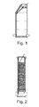
- FIGS 1 and 2 are illustrated typical cross-sections through two different types of manholes leading to a branch pipe.
- the manholes or wells 10 provide access to a branch pipe 12 arranged at a certain distance below the surface of the ground 14.
- a well 10 comprising a number of sections are assembled to form the well.
- the well illustrated in figure 1 has as its uppermost element 10" a cone.
- equipment 1 in the shape of a pest barrier is arranged in the branch pipe 12 in order to deny pests such as rats and the like from travelling through the particular branch pipe.
- the pest barrier 1 is by means of a flexible member 2 connected to a mounting and fixating tool 20 arranged adjacent the upper end of the well 10.
- the mounting and fixating tool 20 is provided with means 3, in this instance in the shape of a clamp or cleat to releasably fasten the flexible member 2 to the mounting and fixating tool 20.
- the flexible members in these embodiments in the shape of a rope 2 is by means of a coupling unit 4 attached to the pest barrier one.
- the coupling unit 4 comprises a spring such that by tightening the rope 2 and fastening it in the fastening means 3 on the mounting and fixating member 20 the spring in the coupling member 4 will ensure that the pest barrier 1 is always subjected to a substantially vertical pull urging/biasing the upper surface of the pest barrier against the inside of the branch pipe 12.
- Figure 3 further illustrates how the pest barrier 1 is arranged in the mouth of the branch pipe 12 by inserting part of the pest barrier 1 inside the branch pipe 12 and by pulling upwards in the flexible member 2 an upper part 5 which in this embodiment is shaped to have a shape corresponding to part of the cross-section of the branch pipe 12 ensuring good contact and thereby good engagement between the pest barrier 1 and the branch pipe.
- the coupling member 4 is in this embodiment an integrated part of the pest barrier 1 and provides a connection between the flexible member 2 and the pest barrier via a spring member such that the spring force will provide a more or less constant upward force forcing the engagement surface 5 against the inside of the branch pipe 12.
- the coupling member 4 is provided with hooks 7 where the hooks 7 are open downwards such that the pest barrier may be attached to a mounting pole (not illustrated) and due to gravity's force on the pest barrier the pole may be released from the hooks 7 when the pest barrier is positioned as illustrated in figure 3 simply by moving the pole further downwards releasing the engagement from the hooks 7.
- the pole is again positioned such that it engages the hooks 7 and the flexible member 2 is then released.
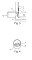
- FIG 4 is illustrated a view inside the branch pipe where it is evident that the engagement surface 5 of the pest barrier 1 is in contact with another part of the branch pipe and due to their mutually corresponding shapes a good and firm contact is established between the pest barrier 1 and the branch pipe 12. This contact is maintained due to the flexible member 2.
- FIG 5 is illustrated various inner diameters of wells, in this embodiment wells having a corrugated profile.
- the mounting and fixating tool is adjustable corresponding to the inner diameter of the well 10. This is in this embodiment achieved by providing the mounting and fixating member with a telescopic bar 30 such that the bar 30 may be extended whereby the ends of the bar fit tightly against the inner wall of the well 10. In the correct position the telescope may be fixated by means of a bolt 31 relatively fixating the two parts of the bar 30 in the position where the ends of the bar 30 is in firm engagement with the inner wall of the well 10.
- the bar 30 is provided with brackets 32, 33.
- the brackets are used to mount equipment such as batteries, data-loggers, GSM, transmitters/receivers, computers, displays etc. which will through wires communicate with the equipment installed in the branch pipe in the lowermost section of the well 10. By arranging this type of equipment adjacent the surface it is easily accessible for maintenance, control etc.
- FIG 6 a mounting and fixation tool 20 where part of the well has been removed in order to illustrate the mounting and fixation tool 20.
- the tool 20 comprises a telescopic bar 30 which length may be expanded and fixated by the bolt 31 as described above with reference to figure 5 .
- an engagement bracket 35 is provided where the engagement bracket 35 is designed to engage in the corrugations on the interior side of the well 10 in order to maintain the tool 20 in a fixed vertical position relative to the branch pipe below.
- guide means for example a pulley or a wheel such that the flexible member 2 will be guided past the bracket and into the clamp or cleat 3.
- the clamp or cleat 3 will releasably secure the flexible member such that it is only possible to draw the flexible member further upwards while positioning the clamp or cleat 3. In order to release the flexible member 2 from the cleat the flexible member is moved out of the cleat and it will then be completely free and only attached to the equipment inserted in the pipe branch below.
- the dimensions of the bar are such that it will also fit inside a corrugation in the interior wall of the well fixing this end of the mounting and fixating tool.
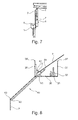
- FIG 8 a further example of a mounting and fixating tool is illustrated.
- the bar 30 is provided with mounting brackets 37, 38 where the distal ends of the mounting brackets 37, 38 are provided with a flange 37', 38'.
- the flanges 37', 38' are designed to engage an upper rim of the manhole such that the bar 30 hangs in the mounting brackets 37, 38 into the interior of the well.
- a clamp or cleat 3 is arranged for fastening of the flexible member 2.
- this configuration may also be provided with brackets 32, 33 for mounting various equipment.
- the mounting and fastening tool may further be provided with a secondary guide member 40.
- the secondary guide member 40 is arranged such that it can pivot relative to the bar 30 in a pivot point 41.
- a first distal end 42 of the secondary guide member means in the shape of a ring or pulley 43 is provided for guiding the flexible member 2 and maintaining the flexible member 2 slidingly in contact with the first distal end 42.
- a locking member 45 Adjacent the opposite end 44 of the secondary guide member 40 is provided a locking member 45 making it possible to fixate the secondary guide member 40 in an angle relative to the bar 30 whereby the flexible member 2 is maintained at a certain distance.
- the coupling member 4 comprises hooks 7 in which the mounting pole (not illustrated) may detachably be arranged such that during insertion/mounting of the equipment 1 the equipment hangs from appropriate projections engaging the hooks 7 in the coupling member 4, and once the flexible member has been tightened whereby the engagement surface 5 of the equipment 1 engages an upper section of the branch pipe the mounting pole may be released from the hooks 7 of the coupling member and thereby from the equipment which is then correctly positioned and maintained in place by the flexible member 2 as described above.
Landscapes
- Engineering & Computer Science (AREA)
- Health & Medical Sciences (AREA)
- Life Sciences & Earth Sciences (AREA)
- Hydrology & Water Resources (AREA)
- Public Health (AREA)
- Water Supply & Treatment (AREA)
- General Engineering & Computer Science (AREA)
- Mechanical Engineering (AREA)
- Sewage (AREA)
- Electric Cable Installation (AREA)
Abstract
a) determining the dimension of the side branch pipe, and selecting the equipment having the appropriate corresponding outer dimension;
b) releasably attaching the equipment to a mounting pole
c) attaching a flexible member to said equipment
d) lowering the equipment down the well by means of the pole, and keeping an end of the flexible member above the well;
e) inserting the equipment into the side branch pipe by means of the pole;
f) tightening the flexible member along the inner wall and above the branch pipe of the well, providing a substantially vertical upwards force on the equipment, thereby fixing the equipment against an upper part of the side branch pipe;
g) fixating the flexible member inside the well;
h) releasing the mounting pole from the equipment, and withdrawing the mounting pole from the well.
Description
- The present invention relates to method of installing equipment in the mouth of a side branch pipe as well as a mounting and fixation tool for use in the method
- In pipe systems such as for example sewer systems or other similar systems it is often desirable to be able to install equipment in the system for various reasons.
- The present invention will be discussed with respect to a sewer system in which a pest barrier or a pest trap is arranged, but the method and mounting tool according to the invention are, as will be clear from the explanation below, not restricted to this type of equipment or to sewer systems, but will be applicable to any pipe system where it is desirable to install any type of equipment which might fit into a side branch.
- Typically installation of equipment at the bottom of a well or in a side branch branching out from the well is carried out by a person entering the well and manually installing the desired equipment, for example by brackets fastened by bolts or the like directly into the side of the well. Due to the inherent danger of working in a well, this operation usually requires the presence of another person on the surface as a safety precaution. In other instances depending on the fluids being transported in the pipe system it may also be necessary to provide adequate ventilation in order to ensure that the working environment is not harmful to the worker inside the well. A further problem arises in all those wells where it is not possible for a person to enter and where the side branches are positioned out of reach. For these wells it is a very cumbersome process to install equipment, and often it is avoided or dispensed with.
- For other purposes it is known to install devices in underground pipes. One example is disclosed in
GB1531213 - A similar device and installation method is disclosed in
US2927609 ,US1889621 , andUS4040450 . Common for all these devices and installation methods is that they are designed to completely block of the flow of medium in the pipe, they are for temporary installation, and they require special access wells or branch pipes in order to be installed. The also rely on hinge constructions in order to swing the device into place in the pipe. - It is therefore an object of the present invention to provide a method as well as a mounting tool which provides a simple, reliable, fast and relatively easy method of installing different types of equipment in side branches of a well.
- The invention addresses this by suggesting a method of installing equipment in the mouth of a side branch pipe in a well of a pipe installation, in particular a sewer system, comprising the following steps:
- a) determining the dimension of the side branch pipe, and selecting the equipment having the appropriate corresponding outer dimension;
- b) releasably attaching the equipment to a mounting pole
- c) attaching a flexible member to said equipment
- d) lowering the equipment down the well by means of the pole, and keeping an end of the flexible member above the well;
- e) inserting the equipment into the side branch pipe by means of the pole;
- f) tightening the flexible member along the inner wall and above the branch pipe of the well, providing a substantially vertical upwards force on the equipment, thereby fixing the equipment against an upper part of the side branch pipe;
- g) fixating the flexible member inside the well;
- h) releasing the mounting pole from the equipment, and withdrawing the mounting pole from the well.
- With this method the size of the well has no influence on the installation procedure of the equipment as long as it is possible to pass the equipment through the well where typically the manhole covering the well will be the decisive dimension which has to be overcome.
- As nothing has to be fastened immediately adjacent the mouth of the side branch pipe it is not necessary for anybody to enter the well, and as such the method may be used for any type of well substantially having the side branch pipe at any depth from the surface. In order to reach down into the well the method requires that the equipment is mounted on a pole, and as such the length of the pole or the person's ability to handle the pole is decisive for the success of the method. In practice installation of equipment in wells at a depth of 7-8 meters has proven possible, even much faster than the traditional method of installing equipment at the bottom of wells.
- The flexible member in combination with the engagement between the equipment and an upper part of the side branch pipe has proven to be an effective system in that the flexible member when tightened will retain the equipment in a stable and fixed relationship with respect to the side branch pipe. This is further emphasized by the fact that the flexible member is positioned substantially adjacent the wall of the well such that the effective pull in the equipment in the upwards direction will be substantially vertical whereby there will be no urge for the equipment to be withdrawn from the side branch pipe. In a further advantageous embodiment the equipment is provided with an upper member having a shape corresponding to another part of the cross-section of the branch pipe such that a firm, reliable and solid engagement may be achieved between the equipment and the branch pipe. In this connection it should be noted that the upper member may be a special part which is attached to any equipment, for example by suitable brackets or the like, or it may be incorporated in the equipment to be installed in the side branch pipe as for example is the case where the equipment to be placed is a pest barrier or a pest trap as will be discussed more extensively below.
- Due to the flexibility of the flexible member a steady and substantially constant biasing force is provided such that the equipment consistently will be urged against the upper section of the side branch pipe. The flexible member may be simply a rope with an inherent flexible characteristic, or the rope where it is engaged with the equipment may be provided with a spring, for example a helical spring, such that the spring force is determining the force by which the equipment is urged against the upper section of the branch pipe.
- In a further advantageous method step step f) is further developed such that a mounting and fixation tool is used, which tool is arranged in an upper part of the well, where said tool comprises means for releasably fastening said tool inside said well, and means for guiding said flexible member close to the inner wall at least a distance immediately above said branch pipe, and means for releasably fixating said flexible member, to said mounting and fixating tool.
- The fixation tool having means for guiding the flexible member close to the wall where for example the means may be a pulley or roller arranged adjacent the end of the fixation tool ensures that the force imparted to the flexible member and thereby to the equipment to be mounted in the branch pipe is and remains as close to the wall of the well as possible. Depending on the constitution of the well wall the mounting and fixation tool may be directly mounted in the sides of the well, especially in wells having a corrugated inner structure or may be equipped with a bracket for engagement with the rim of the well.
- Furthermore, in order to retain the mounting and fixation tool in a fixed position inside the well the mounting and fixation tool may be provided with an expansion mechanism such that the ends of the fixation tool can be urged against the inside wall of the well and be locked in this position. By undoing the lock, which may be constituted by a bolt or the like, it is possible to remove the fixation tool from the well again.
- In addition, the mounting and fixation tool is provided with means for releasably fixating the flexible member, for example in the shape of a clamp or a cleat where the flexible member is a rope, or any other suitable means.
- As not all wells are cylindrical it is in some instances necessary to use a different mounting and fixation tool which is a further development of the mounting and fixation tool mentioned above such that it is possible to mount the mounting and fixation tool adjacent the upper end of the well where the diameter of the well may be substantially less than the diameter of the well further down and at the same time ensure that the flexible member is forced close to the inner wall of the well in order to provide the substantially vertical pull in the equipment to be mounted in the branch pipe.
- It is therefore foreseen that the mounting and fixation tool further comprises a secondary guide member pivotably arranged on the extendable rod in a pivot point between the ends of the rod, where said secondary guide member in a first distal end is provided with means for guiding a flexible member, and adjacent the opposite end projecting past the pivot point is provided with a locking member which will lock the secondary guide member in a determined angle relative to the extendable rod, such that for wells having a larger diameter down hole and/or provided with a cone adjacent the upper end of the well, and where before step f) the flexible member attached to the equipment is treaded through the means for guiding the flexible member arranged in the distal end of the secondary guide member, and the secondary guide member is pivoted into contact or immediately adjacent with the inner side of the well, straight above the branch pipe, in which position the secondary guide member by means of the locking member is locked.
- This secondary guide member is pivotable in relation to the mounting and fixation tool which is releasably fixed to the inner wall of the well such that by pivoting a distal, usually lower end of the secondary guide member, can be brought into contact or almost contact with the wall of the well. By furthermore providing means for guiding the flexible member at the end of the secondary guide member it is ensured that the flexible member, at least for a distance above the equipment which is to be mounted in the branch pipe, is subjected to a substantially vertical pull close to the wall.
- The secondary guide member is furthermore provided with a locking member such that it is possible to fixate the secondary guide member when the distal end of the secondary guide member is in contact or immediately adjacent the wall such that a reliable and durable vertical pull may be exerted on the equipment.
- The invention is also directed to a mounting and fixation tool for use in a method as described above where the mounting and fixation tool is special in that the tool comprises an extendable rod, where means are provided for locking said rod in a determined length, where means are arranged in either end of the rod for engaging the sides of said well, and where guide means adjacent, but not projecting past the distal end of the rod is provided with means for guiding a flexible member, such as a rope or the like, and further that means such as a clamp or cleat for releasably fastening said flexible member is provided on said mounting tool.
- Naturally the mounting and fixation tool does provide and benefit from the same advantages as already discussed above with reference to the method.
- The invention will now be explained in further detail with reference to the accompanying drawing wherein
- Figure 1 and 2
- illustrate typical cross-sections through two different types of man-holes leading to a branch pipe
- Figure 3
- illustrates how the pest barrier 1 is arranged in the mouth of the
branch pipe 12 by inserting part of the pest barrier 1 inside thebranch pipe 12 and by pulling upwards in theflexible member 2 anupper part 5 - Figure 4
- illustrates a view inside the branch pipe
- Figure 5
- illustrates various inner diameters of wells
- Figure 6
- illustrates a mounting and fixation tool
- Figure 7
- illustrates the coupling means 4 between the equipment in the shape of a pest barrier 1 and the
flexible member 2 - Figure 8
- illustrates a further example of a mounting and fixating tool
- In
figures 1 and 2 are illustrated typical cross-sections through two different types of manholes leading to a branch pipe. The manholes orwells 10 provide access to abranch pipe 12 arranged at a certain distance below the surface of the ground 14. In order to connect the manhole opening 16 to the branch pipe 12 a well 10 comprising a number of sections are assembled to form the well. The well illustrated infigure 1 has as itsuppermost element 10" a cone. - In both
figure 1 and figure 2 , equipment 1 in the shape of a pest barrier is arranged in thebranch pipe 12 in order to deny pests such as rats and the like from travelling through the particular branch pipe. The pest barrier 1 is by means of aflexible member 2 connected to a mounting and fixatingtool 20 arranged adjacent the upper end of the well 10. The mounting and fixatingtool 20 is provided withmeans 3, in this instance in the shape of a clamp or cleat to releasably fasten theflexible member 2 to the mounting and fixatingtool 20. - The flexible members in these embodiments in the shape of a
rope 2, is by means of acoupling unit 4 attached to the pest barrier one. Thecoupling unit 4 comprises a spring such that by tightening therope 2 and fastening it in the fastening means 3 on the mounting and fixatingmember 20 the spring in thecoupling member 4 will ensure that the pest barrier 1 is always subjected to a substantially vertical pull urging/biasing the upper surface of the pest barrier against the inside of thebranch pipe 12. -
Figure 3 further illustrates how the pest barrier 1 is arranged in the mouth of thebranch pipe 12 by inserting part of the pest barrier 1 inside thebranch pipe 12 and by pulling upwards in theflexible member 2 anupper part 5 which in this embodiment is shaped to have a shape corresponding to part of the cross-section of thebranch pipe 12 ensuring good contact and thereby good engagement between the pest barrier 1 and the branch pipe. Thecoupling member 4 is in this embodiment an integrated part of the pest barrier 1 and provides a connection between theflexible member 2 and the pest barrier via a spring member such that the spring force will provide a more or less constant upward force forcing theengagement surface 5 against the inside of thebranch pipe 12. - Furthermore, the
coupling member 4 is provided withhooks 7 where thehooks 7 are open downwards such that the pest barrier may be attached to a mounting pole (not illustrated) and due to gravity's force on the pest barrier the pole may be released from thehooks 7 when the pest barrier is positioned as illustrated infigure 3 simply by moving the pole further downwards releasing the engagement from thehooks 7. When desiring to remove the pest barrier the pole is again positioned such that it engages thehooks 7 and theflexible member 2 is then released. - In this situation it will be possible to lower the pest barrier further relative to the side branch pipe and in this manner release the
surface 5 from engagement with the inside of thebranch pipe 12, pull the pest barrier out into the well 10 and by withdrawing the pole with the pest barrier attached retrieve the pest barrier effortlessly to the surface 14. - Naturally, although the present invention is mainly described with respect to placement of a pest barrier, this is for illustrative purposes only, in that any type of equipment fitting inside the branch pipe and having an
engagement surface 5 as well as means for being attached to the mounting pole will be suitable to be placed with the present invention. - In
figure 4 is illustrated a view inside the branch pipe where it is evident that theengagement surface 5 of the pest barrier 1 is in contact with another part of the branch pipe and due to their mutually corresponding shapes a good and firm contact is established between the pest barrier 1 and thebranch pipe 12. This contact is maintained due to theflexible member 2. Infigure 5 is illustrated various inner diameters of wells, in this embodiment wells having a corrugated profile. In order to be able to use the present invention with any type of well diameter, the mounting and fixating tool is adjustable corresponding to the inner diameter of the well 10. This is in this embodiment achieved by providing the mounting and fixating member with atelescopic bar 30 such that thebar 30 may be extended whereby the ends of the bar fit tightly against the inner wall of the well 10. In the correct position the telescope may be fixated by means of abolt 31 relatively fixating the two parts of thebar 30 in the position where the ends of thebar 30 is in firm engagement with the inner wall of the well 10. - In this particular embodiment the
bar 30 is provided withbrackets - In
figure 6 is illustrated a mounting andfixation tool 20 where part of the well has been removed in order to illustrate the mounting andfixation tool 20. Thetool 20 comprises atelescopic bar 30 which length may be expanded and fixated by thebolt 31 as described above with reference tofigure 5 . In oneend 34 of thetool 20 anengagement bracket 35 is provided where theengagement bracket 35 is designed to engage in the corrugations on the interior side of the well 10 in order to maintain thetool 20 in a fixed vertical position relative to the branch pipe below. Inside thebracket 35 is provided guide means, for example a pulley or a wheel such that theflexible member 2 will be guided past the bracket and into the clamp orcleat 3. The clamp orcleat 3 will releasably secure the flexible member such that it is only possible to draw the flexible member further upwards while positioning the clamp orcleat 3. In order to release theflexible member 2 from the cleat the flexible member is moved out of the cleat and it will then be completely free and only attached to the equipment inserted in the pipe branch below. - In the
opposite end 36 of thetool 20 the dimensions of the bar are such that it will also fit inside a corrugation in the interior wall of the well fixing this end of the mounting and fixating tool. - Turning to
figure 8 a further example of a mounting and fixating tool is illustrated. In wells having a corrugated interior wall thebar 30 is provided with mountingbrackets brackets bar 30 hangs in the mountingbrackets cleat 3 is arranged for fastening of theflexible member 2. As was the case with the mounting and fastening tools described with reference tofigure 5 this configuration may also be provided withbrackets - In situations where the well 10 is provided with a
top cone 10" as illustrated infigure 1 the mounting and fastening tool may further be provided with asecondary guide member 40. Thesecondary guide member 40 is arranged such that it can pivot relative to thebar 30 in apivot point 41. In a firstdistal end 42 of the secondary guide member means in the shape of a ring orpulley 43 is provided for guiding theflexible member 2 and maintaining theflexible member 2 slidingly in contact with the firstdistal end 42. - Adjacent the
opposite end 44 of thesecondary guide member 40 is provided a locking member 45 making it possible to fixate thesecondary guide member 40 in an angle relative to thebar 30 whereby theflexible member 2 is maintained at a certain distance. - Turning to
figure 1 it is clear that by pivoting thesecondary guide member 40 it is possible to position the firstdistal end 42 immediately adjacent the inner wall of the well 10 facilitating a substantially vertical pull on the equipment arranged in the side branch pipe in the lower section of the well 10. In this manner, by providing the secondary guide member it becomes possible to adapt the mounting and fastening tool to substantially any configuration of manholes. - Returning to
figure 7 the coupling means 4 between the equipment in the shape of a pest barrier 1 and theflexible member 2 is illustrated. Thecoupling member 4 compriseshooks 7 in which the mounting pole (not illustrated) may detachably be arranged such that during insertion/mounting of the equipment 1 the equipment hangs from appropriate projections engaging thehooks 7 in thecoupling member 4, and once the flexible member has been tightened whereby theengagement surface 5 of the equipment 1 engages an upper section of the branch pipe the mounting pole may be released from thehooks 7 of the coupling member and thereby from the equipment which is then correctly positioned and maintained in place by theflexible member 2 as described above. - The invention has now been explained with reference to a particular example where a pest barrier/pest barrier is used an example. It is, however, clear that any type of equipment which is suitable to be positioned in a side branch pipe in a pipe system will be suitable to be mounted with the inventive mounting and fastening tool according to the invention using a method as disclosed herein.
Claims (7)
- Method of installing equipment in the mouth of a side branch pipe in a well of a pipe installation said well having and inner wall defining the well, in particular a sewer system, comprising the following steps:a) determining the dimension of the side branch pipe, and selecting the equipment having the appropriate corresponding outer dimension;b) releasably attaching the equipment to a mounting polec) attaching a flexible member to said equipmentd) lowering the equipment down the well by means of the pole, and keeping an end of the flexible member above the well;e) inserting the equipment into the side branch pipe by means of the pole;f) tightening the flexible member along the inner wall and above the branch pipe of the well, providing a substantially vertical upwards force on the equipment, thereby fixing the equipment against an upper part of the side branch pipe;g) fixating the flexible member inside the well;h) releasing the mounting pole from the equipment, and withdrawing the mounting pole from the well.
- Method according to claim 1 wherein in step f) a mounting and fixating tool is used, which tool is arranged in an upper part of the well, where said tool comprises means for releasably fastening said tool inside said well, and means for guiding said flexible member close to the inner wall at least a distance immediately above said branch pipe, and means for releasably fixating said flexible member, to said mounting and fixating tool.
- Method according to claim 2 where the mounting and fixating tool further-comprises a secondary guide member pivotably arranged on the extendable rod in a pivot point between the ends of the rod, where said secondary guide member in a first distal end is provided with means for guiding a flexible member, and adjacent the opposite end projecting past the pivot point is provided with a locking member which will lock the secondary guide member in a determined angle relative to the extendable rod, such that for wells having a larger diameter down hole and/or provided with a cone adjacent the upper end of the well, and where before step f) the flexible member attached to the equipment is treaded through the means for guiding the flexible member arranged in the distal end of the secondary guide member, and the secondary guide member is pivoted into contact or immediately adjacent with the inner side of the well, straight above the branch pipe, in which position the secondary guide member by means of the locking member is locked.
- Method according to claim 1, wherein the equipment is provided with an upper member, having a shape corresponding to an upper part of the cross section of the branch pipe.
- Method according to claim 1, wherein the equipment is selected between one or more of the following: a pest extermination device; a pest barrier, a camera, a laser beam emitting and/or receiving device, water flow-meter/-alarm, motion detector.
- Mounting and fixating tool for use in a method as disclosed in any of claims 1 to 5 wherein the tool comprises an extendable rod, where means are provided for locking said rod in a determined length, where means are arranged in either end of the rod for engaging the sides of said well, and where guide means adjacent, but not projecting past the distal end of the rod is provided with means for guiding a flexible member, such as a rope or the like, and further that means such as a clamp or cleat for releasably fastening said flexible member is provided on said mounting tool.
- Mounting tool according to claim 6 wherein a secondary guide member is pivotably arranged on the extendable rod in a pivot point between the ends of the rod, where said secondary guide member in a first distal end is provided with means for guiding a flexible member, and adjacent the opposite end projecting past the pivot point is provided with a locking member which will lock the secondary guide member in a determined angle relative to the extendable rod.
Applications Claiming Priority (1)
| Application Number | Priority Date | Filing Date | Title |
|---|---|---|---|
| DKPA201270427 | 2012-07-13 |
Publications (3)
| Publication Number | Publication Date |
|---|---|
| EP2685015A2 true EP2685015A2 (en) | 2014-01-15 |
| EP2685015A3 EP2685015A3 (en) | 2017-06-14 |
| EP2685015B1 EP2685015B1 (en) | 2019-11-06 |
Family
ID=48747479
Family Applications (1)
| Application Number | Title | Priority Date | Filing Date |
|---|---|---|---|
| EP13175912.8A Active EP2685015B1 (en) | 2012-07-13 | 2013-07-10 | Method of installing equipment in the mouth of a side branch pipe |
Country Status (3)
| Country | Link |
|---|---|
| EP (1) | EP2685015B1 (en) |
| DK (1) | DK2685015T3 (en) |
| ES (1) | ES2772428T3 (en) |
Cited By (4)
| Publication number | Priority date | Publication date | Assignee | Title |
|---|---|---|---|---|
| WO2018050393A1 (en) * | 2016-09-14 | 2018-03-22 | Ratél Aps | Corrosion and clogging resistant poison free rat trap |
| WO2019206627A1 (en) * | 2018-04-24 | 2019-10-31 | Ratél Aps | Rodent trap for use in sewage systems |
| WO2020201241A1 (en) | 2019-04-01 | 2020-10-08 | Hk-Innovision 2011 Aps | Rodent trap with airgun |
| EP3549327B1 (en) | 2016-12-01 | 2022-01-05 | Ratél ApS | Transmission system for monitoring equipment in rat traps positioned in sewers, shafts, and wells |
Citations (4)
| Publication number | Priority date | Publication date | Assignee | Title |
|---|---|---|---|---|
| US1889621A (en) | 1930-11-13 | 1932-11-29 | George S Ankarlo | Gas main stopper |
| US2927609A (en) | 1957-04-08 | 1960-03-08 | Vanderlans & Sons | Temporary plug for pipes |
| US4040450A (en) | 1974-10-28 | 1977-08-09 | Glenys Irene Boundy | Pipe sealing apparatus |
| GB1531213A (en) | 1975-11-10 | 1978-11-08 | Petrone J | Gas main stopper |
Family Cites Families (6)
| Publication number | Priority date | Publication date | Assignee | Title |
|---|---|---|---|---|
| US231015A (en) * | 1880-08-10 | Device for cleaning out street | ||
| GB2148835A (en) * | 1983-11-01 | 1985-06-05 | Ian Dennis Bishop | Winches |
| US5232205A (en) * | 1990-09-19 | 1993-08-03 | Mcvaugh Arthur K | Method of using an extensible boom mechanism for use with cable salvage |
| US5826609A (en) * | 1997-04-11 | 1998-10-27 | Le-Ron Plastics Inc. | Sewer inspection chamber with back-flow prevention valve and method and apparatus for installing valve in sewer inspection chamber |
| US20050111919A1 (en) * | 2003-11-25 | 2005-05-26 | Wentworth Steven W. | Method and apparatus for underground pipeline installation |
| DK2113615T3 (en) * | 2008-03-05 | 2011-08-15 | Nordisk Innovation Aps | Two-way barrier to prevent rats or other pests from entering a sewer system |
-
2013
- 2013-07-10 ES ES13175912T patent/ES2772428T3/en active Active
- 2013-07-10 DK DK13175912.8T patent/DK2685015T3/en active
- 2013-07-10 EP EP13175912.8A patent/EP2685015B1/en active Active
Patent Citations (4)
| Publication number | Priority date | Publication date | Assignee | Title |
|---|---|---|---|---|
| US1889621A (en) | 1930-11-13 | 1932-11-29 | George S Ankarlo | Gas main stopper |
| US2927609A (en) | 1957-04-08 | 1960-03-08 | Vanderlans & Sons | Temporary plug for pipes |
| US4040450A (en) | 1974-10-28 | 1977-08-09 | Glenys Irene Boundy | Pipe sealing apparatus |
| GB1531213A (en) | 1975-11-10 | 1978-11-08 | Petrone J | Gas main stopper |
Cited By (4)
| Publication number | Priority date | Publication date | Assignee | Title |
|---|---|---|---|---|
| WO2018050393A1 (en) * | 2016-09-14 | 2018-03-22 | Ratél Aps | Corrosion and clogging resistant poison free rat trap |
| EP3549327B1 (en) | 2016-12-01 | 2022-01-05 | Ratél ApS | Transmission system for monitoring equipment in rat traps positioned in sewers, shafts, and wells |
| WO2019206627A1 (en) * | 2018-04-24 | 2019-10-31 | Ratél Aps | Rodent trap for use in sewage systems |
| WO2020201241A1 (en) | 2019-04-01 | 2020-10-08 | Hk-Innovision 2011 Aps | Rodent trap with airgun |
Also Published As
| Publication number | Publication date |
|---|---|
| EP2685015A3 (en) | 2017-06-14 |
| DK2685015T3 (en) | 2020-02-10 |
| EP2685015B1 (en) | 2019-11-06 |
| ES2772428T3 (en) | 2020-07-07 |
Similar Documents
| Publication | Publication Date | Title |
|---|---|---|
| EP2685015B1 (en) | Method of installing equipment in the mouth of a side branch pipe | |
| CA2228729C (en) | Extendible safety posts for manhole ladders | |
| US9410838B2 (en) | Adjustable underground meter installation | |
| US20100133389A1 (en) | Device for supporting a safety line | |
| US4474513A (en) | Portable handheld device for forming aligned holes | |
| US20110158783A1 (en) | Ladder system | |
| CA2776074C (en) | Adjustable underground meter installation | |
| US10730732B1 (en) | Pipe-hoisting strap installation tool | |
| US10569311B2 (en) | Plumbing device and associated systems and methods | |
| US20150276106A1 (en) | Cleanout boom | |
| NL1036953C2 (en) | Mounting assembly with supporting bracket for mounting a water treatment unit in a water reservoir. | |
| KR200489266Y1 (en) | Chain block mounting structure for opening and closing valve chamber | |
| JP7077837B2 (en) | Ladder hooking auxiliary metal fittings | |
| US6263747B1 (en) | Remote installation method and tool | |
| US11680831B2 (en) | Laser lowering device | |
| JP6128690B2 (en) | Connection structure between receiving frame and lid at ground opening of underground space structure | |
| EP2241688B1 (en) | Mounting assembly with a mounting tool for mounting a water treatment unit in a water reservoir | |
| US20230102551A1 (en) | Improved Pole Joint | |
| AU2005101079A4 (en) | A mount for a luminaire | |
| JP2011058323A (en) | Work safety device in sewerage system | |
| US20210238854A1 (en) | Roof or wall hole closing device | |
| NL1036869C2 (en) | Mounting assembly with a mounting tool for mounting a water treatment unit in a water reservoir. | |
| AU2020200544A1 (en) | Pipe installation apparatus, system, and method | |
| GB2512271A (en) | Apparatus and method for installation and protection of sub sea cables | |
| JP2015165066A (en) | Ladder fixing jig and set of ladder fixing jig and safety block attachment jig |
Legal Events
| Date | Code | Title | Description |
|---|---|---|---|
| PUAI | Public reference made under article 153(3) epc to a published international application that has entered the european phase |
Free format text: ORIGINAL CODE: 0009012 |
|
| AK | Designated contracting states |
Kind code of ref document: A2 Designated state(s): AL AT BE BG CH CY CZ DE DK EE ES FI FR GB GR HR HU IE IS IT LI LT LU LV MC MK MT NL NO PL PT RO RS SE SI SK SM TR |
|
| AX | Request for extension of the european patent |
Extension state: BA ME |
|
| PUAL | Search report despatched |
Free format text: ORIGINAL CODE: 0009013 |
|
| AK | Designated contracting states |
Kind code of ref document: A3 Designated state(s): AL AT BE BG CH CY CZ DE DK EE ES FI FR GB GR HR HU IE IS IT LI LT LU LV MC MK MT NL NO PL PT RO RS SE SI SK SM TR |
|
| AX | Request for extension of the european patent |
Extension state: BA ME |
|
| RIC1 | Information provided on ipc code assigned before grant |
Ipc: F16L 55/24 20060101ALI20170505BHEP Ipc: E03F 9/00 20060101ALI20170505BHEP Ipc: F16L 55/124 20060101ALI20170505BHEP Ipc: F16L 55/10 20060101ALI20170505BHEP Ipc: E03F 5/02 20060101AFI20170505BHEP Ipc: E03F 7/04 20060101ALI20170505BHEP Ipc: E03F 7/06 20060101ALI20170505BHEP |
|
| STAA | Information on the status of an ep patent application or granted ep patent |
Free format text: STATUS: REQUEST FOR EXAMINATION WAS MADE |
|
| 17P | Request for examination filed |
Effective date: 20171214 |
|
| RAX | Requested extension states of the european patent have changed |
Extension state: BA Payment date: 20171214 Extension state: ME Payment date: 20171214 |
|
| RBV | Designated contracting states (corrected) |
Designated state(s): AL AT BE BG CH CY CZ DE DK EE ES FI FR GB GR HR HU IE IS IT LI LT LU LV MC MK MT NL NO PL PT RO RS SE SI SK SM TR |
|
| GRAP | Despatch of communication of intention to grant a patent |
Free format text: ORIGINAL CODE: EPIDOSNIGR1 |
|
| STAA | Information on the status of an ep patent application or granted ep patent |
Free format text: STATUS: GRANT OF PATENT IS INTENDED |
|
| INTG | Intention to grant announced |
Effective date: 20190117 |
|
| GRAJ | Information related to disapproval of communication of intention to grant by the applicant or resumption of examination proceedings by the epo deleted |
Free format text: ORIGINAL CODE: EPIDOSDIGR1 |
|
| STAA | Information on the status of an ep patent application or granted ep patent |
Free format text: STATUS: REQUEST FOR EXAMINATION WAS MADE |
|
| GRAP | Despatch of communication of intention to grant a patent |
Free format text: ORIGINAL CODE: EPIDOSNIGR1 |
|
| STAA | Information on the status of an ep patent application or granted ep patent |
Free format text: STATUS: GRANT OF PATENT IS INTENDED |
|
| INTC | Intention to grant announced (deleted) | ||
| INTG | Intention to grant announced |
Effective date: 20190529 |
|
| GRAS | Grant fee paid |
Free format text: ORIGINAL CODE: EPIDOSNIGR3 |
|
| GRAA | (expected) grant |
Free format text: ORIGINAL CODE: 0009210 |
|
| STAA | Information on the status of an ep patent application or granted ep patent |
Free format text: STATUS: THE PATENT HAS BEEN GRANTED |
|
| AK | Designated contracting states |
Kind code of ref document: B1 Designated state(s): AL AT BE BG CH CY CZ DE DK EE ES FI FR GB GR HR HU IE IS IT LI LT LU LV MC MK MT NL NO PL PT RO RS SE SI SK SM TR |
|
| AX | Request for extension of the european patent |
Extension state: BA ME |
|
| REG | Reference to a national code |
Ref country code: GB Ref legal event code: FG4D |
|
| REG | Reference to a national code |
Ref country code: CH Ref legal event code: EP Ref country code: AT Ref legal event code: REF Ref document number: 1198905 Country of ref document: AT Kind code of ref document: T Effective date: 20191115 |
|
| REG | Reference to a national code |
Ref country code: DE Ref legal event code: R096 Ref document number: 602013062451 Country of ref document: DE |
|
| REG | Reference to a national code |
Ref country code: IE Ref legal event code: FG4D |
|
| REG | Reference to a national code |
Ref country code: NO Ref legal event code: T2 Effective date: 20191106 |
|
| REG | Reference to a national code |
Ref country code: DK Ref legal event code: T3 Effective date: 20200205 |
|
| REG | Reference to a national code |
Ref country code: SE Ref legal event code: TRGR |
|
| RAP2 | Party data changed (patent owner data changed or rights of a patent transferred) |
Owner name: RATEL APS |
|
| REG | Reference to a national code |
Ref country code: NL Ref legal event code: MP Effective date: 20191106 |
|
| REG | Reference to a national code |
Ref country code: LT Ref legal event code: MG4D |
|
| PG25 | Lapsed in a contracting state [announced via postgrant information from national office to epo] |
Ref country code: BG Free format text: LAPSE BECAUSE OF FAILURE TO SUBMIT A TRANSLATION OF THE DESCRIPTION OR TO PAY THE FEE WITHIN THE PRESCRIBED TIME-LIMIT Effective date: 20200206 Ref country code: LT Free format text: LAPSE BECAUSE OF FAILURE TO SUBMIT A TRANSLATION OF THE DESCRIPTION OR TO PAY THE FEE WITHIN THE PRESCRIBED TIME-LIMIT Effective date: 20191106 Ref country code: FI Free format text: LAPSE BECAUSE OF FAILURE TO SUBMIT A TRANSLATION OF THE DESCRIPTION OR TO PAY THE FEE WITHIN THE PRESCRIBED TIME-LIMIT Effective date: 20191106 Ref country code: NL Free format text: LAPSE BECAUSE OF FAILURE TO SUBMIT A TRANSLATION OF THE DESCRIPTION OR TO PAY THE FEE WITHIN THE PRESCRIBED TIME-LIMIT Effective date: 20191106 Ref country code: LV Free format text: LAPSE BECAUSE OF FAILURE TO SUBMIT A TRANSLATION OF THE DESCRIPTION OR TO PAY THE FEE WITHIN THE PRESCRIBED TIME-LIMIT Effective date: 20191106 Ref country code: PL Free format text: LAPSE BECAUSE OF FAILURE TO SUBMIT A TRANSLATION OF THE DESCRIPTION OR TO PAY THE FEE WITHIN THE PRESCRIBED TIME-LIMIT Effective date: 20191106 Ref country code: GR Free format text: LAPSE BECAUSE OF FAILURE TO SUBMIT A TRANSLATION OF THE DESCRIPTION OR TO PAY THE FEE WITHIN THE PRESCRIBED TIME-LIMIT Effective date: 20200207 Ref country code: PT Free format text: LAPSE BECAUSE OF FAILURE TO SUBMIT A TRANSLATION OF THE DESCRIPTION OR TO PAY THE FEE WITHIN THE PRESCRIBED TIME-LIMIT Effective date: 20200306 |
|
| PG25 | Lapsed in a contracting state [announced via postgrant information from national office to epo] |
Ref country code: IS Free format text: LAPSE BECAUSE OF FAILURE TO SUBMIT A TRANSLATION OF THE DESCRIPTION OR TO PAY THE FEE WITHIN THE PRESCRIBED TIME-LIMIT Effective date: 20200306 Ref country code: HR Free format text: LAPSE BECAUSE OF FAILURE TO SUBMIT A TRANSLATION OF THE DESCRIPTION OR TO PAY THE FEE WITHIN THE PRESCRIBED TIME-LIMIT Effective date: 20191106 Ref country code: RS Free format text: LAPSE BECAUSE OF FAILURE TO SUBMIT A TRANSLATION OF THE DESCRIPTION OR TO PAY THE FEE WITHIN THE PRESCRIBED TIME-LIMIT Effective date: 20191106 |
|
| PG25 | Lapsed in a contracting state [announced via postgrant information from national office to epo] |
Ref country code: AL Free format text: LAPSE BECAUSE OF FAILURE TO SUBMIT A TRANSLATION OF THE DESCRIPTION OR TO PAY THE FEE WITHIN THE PRESCRIBED TIME-LIMIT Effective date: 20191106 |
|
| REG | Reference to a national code |
Ref country code: ES Ref legal event code: FG2A Ref document number: 2772428 Country of ref document: ES Kind code of ref document: T3 Effective date: 20200707 |
|
| PG25 | Lapsed in a contracting state [announced via postgrant information from national office to epo] |
Ref country code: CZ Free format text: LAPSE BECAUSE OF FAILURE TO SUBMIT A TRANSLATION OF THE DESCRIPTION OR TO PAY THE FEE WITHIN THE PRESCRIBED TIME-LIMIT Effective date: 20191106 Ref country code: RO Free format text: LAPSE BECAUSE OF FAILURE TO SUBMIT A TRANSLATION OF THE DESCRIPTION OR TO PAY THE FEE WITHIN THE PRESCRIBED TIME-LIMIT Effective date: 20191106 Ref country code: EE Free format text: LAPSE BECAUSE OF FAILURE TO SUBMIT A TRANSLATION OF THE DESCRIPTION OR TO PAY THE FEE WITHIN THE PRESCRIBED TIME-LIMIT Effective date: 20191106 |
|
| REG | Reference to a national code |
Ref country code: DE Ref legal event code: R097 Ref document number: 602013062451 Country of ref document: DE |
|
| REG | Reference to a national code |
Ref country code: AT Ref legal event code: MK05 Ref document number: 1198905 Country of ref document: AT Kind code of ref document: T Effective date: 20191106 |
|
| PG25 | Lapsed in a contracting state [announced via postgrant information from national office to epo] |
Ref country code: SM Free format text: LAPSE BECAUSE OF FAILURE TO SUBMIT A TRANSLATION OF THE DESCRIPTION OR TO PAY THE FEE WITHIN THE PRESCRIBED TIME-LIMIT Effective date: 20191106 Ref country code: SK Free format text: LAPSE BECAUSE OF FAILURE TO SUBMIT A TRANSLATION OF THE DESCRIPTION OR TO PAY THE FEE WITHIN THE PRESCRIBED TIME-LIMIT Effective date: 20191106 |
|
| PLBE | No opposition filed within time limit |
Free format text: ORIGINAL CODE: 0009261 |
|
| STAA | Information on the status of an ep patent application or granted ep patent |
Free format text: STATUS: NO OPPOSITION FILED WITHIN TIME LIMIT |
|
| 26N | No opposition filed |
Effective date: 20200807 |
|
| PG25 | Lapsed in a contracting state [announced via postgrant information from national office to epo] |
Ref country code: AT Free format text: LAPSE BECAUSE OF FAILURE TO SUBMIT A TRANSLATION OF THE DESCRIPTION OR TO PAY THE FEE WITHIN THE PRESCRIBED TIME-LIMIT Effective date: 20191106 Ref country code: SI Free format text: LAPSE BECAUSE OF FAILURE TO SUBMIT A TRANSLATION OF THE DESCRIPTION OR TO PAY THE FEE WITHIN THE PRESCRIBED TIME-LIMIT Effective date: 20191106 |
|
| PG25 | Lapsed in a contracting state [announced via postgrant information from national office to epo] |
Ref country code: IT Free format text: LAPSE BECAUSE OF FAILURE TO SUBMIT A TRANSLATION OF THE DESCRIPTION OR TO PAY THE FEE WITHIN THE PRESCRIBED TIME-LIMIT Effective date: 20191106 |
|
| PG25 | Lapsed in a contracting state [announced via postgrant information from national office to epo] |
Ref country code: MC Free format text: LAPSE BECAUSE OF FAILURE TO SUBMIT A TRANSLATION OF THE DESCRIPTION OR TO PAY THE FEE WITHIN THE PRESCRIBED TIME-LIMIT Effective date: 20191106 |
|
| REG | Reference to a national code |
Ref country code: CH Ref legal event code: PL |
|
| REG | Reference to a national code |
Ref country code: BE Ref legal event code: MM Effective date: 20200731 |
|
| PG25 | Lapsed in a contracting state [announced via postgrant information from national office to epo] |
Ref country code: LI Free format text: LAPSE BECAUSE OF NON-PAYMENT OF DUE FEES Effective date: 20200731 Ref country code: CH Free format text: LAPSE BECAUSE OF NON-PAYMENT OF DUE FEES Effective date: 20200731 Ref country code: LU Free format text: LAPSE BECAUSE OF NON-PAYMENT OF DUE FEES Effective date: 20200710 Ref country code: FR Free format text: LAPSE BECAUSE OF NON-PAYMENT OF DUE FEES Effective date: 20200731 |
|
| PG25 | Lapsed in a contracting state [announced via postgrant information from national office to epo] |
Ref country code: BE Free format text: LAPSE BECAUSE OF NON-PAYMENT OF DUE FEES Effective date: 20200731 |
|
| PG25 | Lapsed in a contracting state [announced via postgrant information from national office to epo] |
Ref country code: IE Free format text: LAPSE BECAUSE OF NON-PAYMENT OF DUE FEES Effective date: 20200710 |
|
| PG25 | Lapsed in a contracting state [announced via postgrant information from national office to epo] |
Ref country code: TR Free format text: LAPSE BECAUSE OF FAILURE TO SUBMIT A TRANSLATION OF THE DESCRIPTION OR TO PAY THE FEE WITHIN THE PRESCRIBED TIME-LIMIT Effective date: 20191106 Ref country code: MT Free format text: LAPSE BECAUSE OF FAILURE TO SUBMIT A TRANSLATION OF THE DESCRIPTION OR TO PAY THE FEE WITHIN THE PRESCRIBED TIME-LIMIT Effective date: 20191106 Ref country code: CY Free format text: LAPSE BECAUSE OF FAILURE TO SUBMIT A TRANSLATION OF THE DESCRIPTION OR TO PAY THE FEE WITHIN THE PRESCRIBED TIME-LIMIT Effective date: 20191106 |
|
| PG25 | Lapsed in a contracting state [announced via postgrant information from national office to epo] |
Ref country code: MK Free format text: LAPSE BECAUSE OF FAILURE TO SUBMIT A TRANSLATION OF THE DESCRIPTION OR TO PAY THE FEE WITHIN THE PRESCRIBED TIME-LIMIT Effective date: 20191106 |
|
| P01 | Opt-out of the competence of the unified patent court (upc) registered |
Effective date: 20230328 |
|
| P02 | Opt-out of the competence of the unified patent court (upc) changed |
Effective date: 20230519 |
|
| PGFP | Annual fee paid to national office [announced via postgrant information from national office to epo] |
Ref country code: NO Payment date: 20230727 Year of fee payment: 11 Ref country code: GB Payment date: 20230727 Year of fee payment: 11 Ref country code: ES Payment date: 20230804 Year of fee payment: 11 |
|
| PGFP | Annual fee paid to national office [announced via postgrant information from national office to epo] |
Ref country code: SE Payment date: 20230727 Year of fee payment: 11 Ref country code: DK Payment date: 20230727 Year of fee payment: 11 Ref country code: DE Payment date: 20230727 Year of fee payment: 11 |