EP3549314B1 - Opportunistische qos-implementierung - Google Patents
Opportunistische qos-implementierung Download PDFInfo
- Publication number
- EP3549314B1 EP3549314B1 EP17803971.5A EP17803971A EP3549314B1 EP 3549314 B1 EP3549314 B1 EP 3549314B1 EP 17803971 A EP17803971 A EP 17803971A EP 3549314 B1 EP3549314 B1 EP 3549314B1
- Authority
- EP
- European Patent Office
- Prior art keywords
- application
- service
- quality
- network
- service setting
- Prior art date
- Legal status (The legal status is an assumption and is not a legal conclusion. Google has not performed a legal analysis and makes no representation as to the accuracy of the status listed.)
- Active
Links
Images


Classifications
-
- H—ELECTRICITY
- H04—ELECTRIC COMMUNICATION TECHNIQUE
- H04L—TRANSMISSION OF DIGITAL INFORMATION, e.g. TELEGRAPHIC COMMUNICATION
- H04L47/00—Traffic control in data switching networks
- H04L47/10—Flow control; Congestion control
- H04L47/24—Traffic characterised by specific attributes, e.g. priority or QoS
- H04L47/2458—Modification of priorities while in transit
-
- H—ELECTRICITY
- H04—ELECTRIC COMMUNICATION TECHNIQUE
- H04L—TRANSMISSION OF DIGITAL INFORMATION, e.g. TELEGRAPHIC COMMUNICATION
- H04L47/00—Traffic control in data switching networks
- H04L47/10—Flow control; Congestion control
- H04L47/24—Traffic characterised by specific attributes, e.g. priority or QoS
- H04L47/2475—Traffic characterised by specific attributes, e.g. priority or QoS for supporting traffic characterised by the type of applications
-
- H—ELECTRICITY
- H04—ELECTRIC COMMUNICATION TECHNIQUE
- H04W—WIRELESS COMMUNICATION NETWORKS
- H04W28/00—Network traffic management; Network resource management
- H04W28/02—Traffic management, e.g. flow control or congestion control
- H04W28/0268—Traffic management, e.g. flow control or congestion control using specific QoS parameters for wireless networks, e.g. QoS class identifier [QCI] or guaranteed bit rate [GBR]
-
- H—ELECTRICITY
- H04—ELECTRIC COMMUNICATION TECHNIQUE
- H04W—WIRELESS COMMUNICATION NETWORKS
- H04W4/00—Services specially adapted for wireless communication networks; Facilities therefor
- H04W4/50—Service provisioning or reconfiguring
Definitions
- the present invention relates to a method of modifying an existing quality of service, QoS, setting in a mobile communications network between a user equipment, UE, and a base station.
- Cellular mobile communications networks provide mobile data communication to mobile devices within their coverage area.
- the service is based on cells spanned by base stations providing the air interface and a core network providing the backbone for the base stations as well as authentication, data routing and other services to the mobile device (UE).
- base stations providing the air interface
- core network providing the backbone for the base stations as well as authentication, data routing and other services to the mobile device (UE).
- UE mobile device
- the mobile network architecture for 2G/3G systems is described in 3GPP TS 23.060, and that of the 4G system is described in 3GPP TS 23.401.
- the systems offer data communication between a UE and a data network based on logical connections between the UE and the respective gateway (packet data network, PDN, connections). Most of these connections are IP-based, therefore the respective gateway allocates an IP-address from the data network to the UE which is valid for the respective PDN connection throughout the lifetime of the connection.
- a UE may have multiple PDN connections to a data network with the same IP-address used by the UE, it may have multiple connections with different IP-addresses to different data networks (e.g. Internet, MMS, IMS).
- SDF service data flows
- QoS quality of service
- a service manager co-ordinates the functions of the control plane for establishing, modifying and maintaining the service it is responsible for.
- a QoS change is implemented by sending a "Modify PDP Context Request" message, which includes the new QoS (see 3GPP TS 24.008).
- next generation mobile network For the next generation mobile network (“5G” or “Next Generation (NG)”), the architecture will offer more flexibility allowing operators to adapt the services offered to the UE to its actual needs.
- a single connection between UE and a data network is denoted as a packet data unit, PDU, session. It is setup and maintained very flexibly and more than one PDU session to the same data network for a single UE may exist, e.g. with different IP-address (so called multi-homing) and/or with a different quality of service, QoS.
- PDU flows may exist that constitute, similar to the SDF in the legacy core network, the smallest granularity if QoS treatment.
- PDU flows with (slightly) different QoS settings may exist within one PDU session.
- Multiple PDU sessions to one data network may exist with more impacting differences in QoS settings, e.g. different IP-address-preservation settings and resulting different mobility treatment or with different IP-addresses.
- FIG. 7.6.2-1 of 3GPP TR 23.799 a working document for the 5G architecture, depicts a foreseen non-roaming network architecture for 5G for UEs concurrently accessing a local and a central data network using multiple PDU sessions.
- the UE connects to a next generation (radio) access network (NG (R)AN) which is connected via a next generation core (network) user-plane (UP) function to a data network (DN).
- the UP function is basically a network router and/or gateway; it may be present multiple times cascaded per PDU session between a single UE and a specific data network.
- the single UP function that builds the end point of the operator network towards a data network e.g. internet or IMS
- IMS internet or internet or IMS
- the terminating UP functions was denoted packet gateway (PGW) in the LTE core network
- SGW serving gateway
- T serving gateway
- the UE and the base station are connected to the next generation mobility management function (MMF) which controls the UE registration and mobility and which routes control messages related to PDU sessions (setup of new PDU sessions, modifications, release etc.) to the session management function (SMF).
- MMF next generation mobility management function
- the SMF communicates with a policy control-plane function and an application function, the latter residing e.g. in a third party application server.
- a UE can be connected via multiple accesses (e.g. NG radio and LTE) and have different PDU sessions that are routed via different UP functions to different or the same data networks.
- PDU session e.g. IP-type, which is the typical case, an IP-address is allocated to the UE.
- a UE may also communicate with multiple session management functions, each used for some of the UE's PDU sessions.
- a single mobility management function MMF
- TR 23.799 describes potential mobility procedures for 5G in multiple variants that define mobility requirements for a UE and its PDU sessions.
- SSC session and service continuity
- different so called session and service continuity (SSC) modes 1, 2 and 3 may be defined for a 5G system.
- SSC session and service continuity
- the mode describes whether and how the terminating user plane function (TUPF), i.e. the gateway towards a data network, may be changed as a result of UE mobility.
- TUPF terminating user plane function
- Mobility here means either within one radio technology or between radio technologies, resulting in the necessity to change the TUPF.
- a UE moving from one cell to another may leave the area a TUPF can efficiently serve or a UE changing from 5G to WLAN / fixed access may have to change to a TUPF that is able to serve fixed connections.
- the UE may indicate the requested session and service continuity (SSC) mode as part of the PDU session setup signalling to the network.
- SSC session and service continuity
- the UE may determine the required SSC mode as described in IETF draft "draft-ietf-dmm-ondemand-mobility", which describes an application programming Interface (API) extension for applications to request a socket and thereby requesting a nomadic, sustained or fixed IP-address. These correspond to SSC2 (nomadic) or SSC1 or SSC3 for (sustained or fixed).
- API application programming Interface
- SSC1 Typical examples for applications requiring SSC1 are browser-applications contacting a web-server for a service, they usually cannot cope with a change of IP-address.
- SSC3 is typically used by voice applications (skype, SIP based), which have means implemented to overcome occasional IP-address changes.
- SSC2 is used for services only having short communicating sessions like messaging apps or DNS service clients. These are not seriously impacted by IP-address changes.
- Session Classes for a specific PDU session of a UE alternatively to SSCs.
- the classes are also defined for cases of mobility and a resulting change of a user plane function (UPF). They distinguish whether resources of a PDU session to be moved to the target are setup before the actual TUPF change (so called Session pre-setup similar to handover in LTE) or after the TUPF change (Session post-setup).
- the two classes basically describe a very similar distinction as SSC2 (like session post-setup) and SSC3 (like session pre-setup).
- a UE may have multiple connections to the same data network and at the same time connections to different data networks and all of these connections can be setup according to their respective requirements, i.e. with different service continuity and IP-address preservation treatment.
- PDU flows define data with exactly the same treatment while several such flows within a connection may differ in QoS.
- an application may have strict requirements. For example, an application may have a strict requirement for keeping its IP-address or for service continuity having short or basically no disruption caused by the device's mobility. Another application may be basically indifferent about IP-address changes or longer data delivery disruption and even loss of data packets due to mobility.
- US 2008/0132268 A1 describes a technique for initiating a first application with a first QoS setting and when a PDP context changes, updating the QoS setting.
- US 2014/0162676 A1 describes the setting up of a new bearer in response to a demand for a new service with a higher QoS.
- the present invention provides a method of providing a quality of service setting for a first application operating on a user equipment device according to claim 1.
- the invention further provides a corresponding UE according to claim 12 and a corresponding network equipment device according to claim 15.
- the present invention provides means for applications to request services from a mobile network according to their strict requirements and additionally allows an indication that these applications would benefit from better service in terms of preserved IP-addresses, reduced disruption time and/or reduced data loss.
- the invention also allows a mobile network that provides to first applications on mobile devices connections to data networks serving the first application's strict quality requirements as long as it can avoid to provide connections with better quality. If the network has to provide other applications on the mobile device a connection to the data network with better service, it provides the better service also to the first application if the first application indicated to benefit from better service.
- the invention further provides a network being able to provide first services according to a first quality level and as a result of a second service being requested with a second (better) quality level, providing first services that benefit from better service and the second services according to the second quality level. This may include to continue serving first services that do not benefit from better service with the first quality level.
- serving a mobile device may be done more efficiently and in a way that increases the quality of experience of the mobile device user.
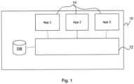
- Fig. 1 depicts a schematic representation of mobile device in the form of a UE 10 comprising communication interface 12.
- This interface may consist of a cellular modem able to communicate according to a fifth generation cellular communication standard, LTE and UMTS.
- the communication interface may also include WLAN (WiFi) and other communication technologies.
- Fig. 1 shows in an exemplary manner three applications 14 (in short "apps") usable on the device. There may be many more apps on the device, e.g. as part of the device's operating system (OS) or downloaded into the device on request by the device's user.
- apps in short "apps”
- OS operating system
- the apps 14 need to communicate with other devices, e.g. a server in the internet having a peer application running, they request a communication service from the communication interface 12.
- the request may be directly provided or, more likely, it may be placed as a procedure call in the operating system.
- the request may provide information about the quality of service the application requires to work properly (strict requirements).
- the quality of service information may include requirements on quality of service measures like maximum disruption time, average or maximum packet loss and IP-address preservation needs.
- the request may also include additional quality of service information providing information about alternative quality of service with which the application can provide its service in a way that is preferable for the user, the device and/or the network.
- This information may be very simple, e.g. in the form of flags for the three QoS measures above, each flag indicating "can profit from better service” or "cannot profit from better service”.
- the information may also be more sophisticated, e.g. in the form of a parameter whose value indicates a level of benefit that is well known by the UE and/or the network (in other words, the values are standardized).
- the meaning of example values could be:
- the strict requirements of the application i.e. quality of service information, and the additional quality of service information may also be communicated together, e.g. as a value range.
- quality of service information i.e. quality of service information
- additional quality of service information may also be communicated together, e.g. as a value range.
- an app could request internet service with 20 - 100 Mbyte/s bandwidth and potential IP-address changes from occasional to never.
- the lower limit of the respective value range may be interpreted as a strict or minimum requirement by the app, in this case 20 Mbyte/s and only occasional IP-address changes; whereas all values above up to the upper limit would be preferable.
- the QoS information may be provided as described above by the application to the OS and / or the communication means to be taken into account.
- the information may alternatively be stored in a database 16 on the mobile device.
- the database may store policies regarding quality of service information and additional quality of service information for various applications as described above.
- the OS or the communication means may look up the respective QoS and additional QoS information in the data base.
- QoS and additional QoS information is stored in the network, e.g. in a data base in the network shown.
- a request for a network connection to a data network or for an additional data flow to a data network for a specific application may contain information that allows the network to identify the application or the service requesting the connection or the flow. This identity may enable the network to look up the respective QoS and additional QoS in the database in the network.
- the database may store policies regarding quality of service information and additional quality of service information for various applications either subscriber specific or for multiple/all subscribers.
- the communication means in the UE will react on the request by the application by initiating a new data flow or (in case the app needs multiple data flows) new data flows. If no appropriate PDU session exists, the UE will issue a request for a new PDU session towards the network. Otherwise it may select an existing PDU session for delivery of the flow(s).
- No appropriate PDU session may exist because no PDU session to the requested data network is setup by the UE or the existing PDU sessions with the data network have the wrong QoS or are exclusively used by other applications.
- the network may have configured the UE with filters for PDU session selection for new flows which filters indicate the need to setup a new PDU session for the new flow(s) based on the requested service parameters.
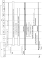
- Fig. 2 shows a setup of a new PDU session initiated by an application on the UE.
- the different elements or functions involved in the PDU session setup procedure are shown.
- a UE 20 including two applications (App1 and App2) and a communication interface Comm is depicted in the figure.
- the UE can directly talk to the access network AN that may be a radio access network communicating with the UE via antennas.
- the access network AN may also be a fixed network or a hybrid fixed and WiFi network.
- the access network AN is connected to a core network CN having different functions, most functions are shown only once but may potentially exists multiple times in a core network.
- the core network CN also includes a database DB. Data may be exchanged between the core network and one or several data networks DN.
- MM Context Establishment which may consist of multiple messages to be exchanged.
- an application e.g. App 1
- requests a data communication service with a data network DN as depicted in step 1 e.g. via an application programming interface (API)
- the communication interface in the UE will check whether the UE already has a PDU session to this DN and if so, whether or not the PDU session is applicable for additional transport of the requested service.
- App 1 may include in its request QoS parameters describing the service quality required to perform the service. As an example, App 1 may indicate that occasional IP-address change is acceptable for the application.
- App 1 may also include additional service quality parameters addQoS the application may make use of, e.g. App 1 may include the information that IP-address preservation would save significant application layer control signalling.
- the additional service quality parameters may alternatively also be received from a UE-internal data base in an optional step 1a.
- the UE will request PDU session establishment from the MMF via the AN as shown as step 2.
- This request may contain the QoS description as received from the app including the additional QoS description.
- the MMF will select an appropriate SMF and forward the request including QoS and additional QoS in step 3.
- the SMF will base the following PDU session setup procedure purely on the QoS requirements of the app.
- the SMF may store the additional QoS parameters (step 4) so that they can be used in case future PDU sessions may provide the additional QoS and may allow App 1 to be served accordingly.
- the SMF may authenticate and authorize the UE and the session parameters with the DN (step 5), get policy information from the PCF (step 6) and select an appropriate UPF or UPFs if the service requires more than one UPF.
- the SMF may receive application specific QoS information from any data base within the core network or from the DN, especially when no such information has been received in step 1 and 1a.
- the PDU session resource establishment is triggered based on the QoS parameters, the QoS authorized by the DN and the operator policy.
- the PDU session resource establishment is performed with the AN (step 8) and the respective UPF (step 9).
- the terminating gateway (TUPF) is provided with filter information steering the respective DL data to be transported via the newly established PDU session.
- the UE is informed about completion of the PDU session establishment in step 10 including filter information steering the respective UL data from App 1 to be transferred over the new PDU session.
- the application may be informed that the requested service is available which may be accomplished by additional information about the QoS actually provided by the network.
- Data transfer can now happen between App 1 and DN via AN and the selected UPF with the provided QoS based on the application's requirements.
- additional QoS information is submitted within the service request and/or PDU session establishment request from the application via communication interface to the network and its storage in the core network, e.g. in the SMF.
- the additional QoS information is received from databases in the UE or core network.
- Fig. 3 the setup of an additional PDU session for a second app is depicted.
- the figure assumes as a prerequisite the establishment of a first PDU session according to Fig. 2 as described above and shown as step 0 in Fig. 3 .
- Data transfer between App 1 and data network DN via access network AN and the selected UPF(s) may still occur as depicted.
- App 2 may request data delivery service with an application-specific QoS from the communication means, e.g. App 2 may request a service including IP-address preservation during the connection.
- the QoS of App 2 may be received from the application, from a UE-internal database or from a core network based database.
- a different embodiment of this invention could have App 2 request a QoS that demands session continuity with seamless mobility, i.e. handover pre-preparation and low or no disruption time due to mobility which may be provided with a separate PDU Session.
- Fig. 3 shows the PDU session establishment process very similar to that depicted in Fig. 2 .
- App 2 requests data delivery service with a QoS (step 1) that triggers the communication interface of the UE to request a new PDU Session (step 2).
- the respective request is forwarded to the appropriate SMF in step 3 and the UE and the new PDU session may be authenticated and authorized with the DN in step 4.
- the SMF After policies are received from the PCF (step 5) the SMF knows all details of the PDU session to be established.
- the SMF can now check stored information about packet flows already established. Especially, the SMF may check for packet flows having a current QoS that is lower than the one to be established for the new PDU session and having indicated to benefit from at least one different parameter setting that is applicable for the new PDU session. In the example, the SMF may find App 1 to benefit from IP-address preservation. As a result, the SMF in addition to setup of the PDU session switches the packet flow of App 1 from the first PDU session setup in Fig. 2 to the new PDU session to be established, depicted as step 6 in Fig. 3 and denoted generally "React on addQoS".
- New UPF(s) the new PDU session is shown to be established via a different UPF, denoted "New UPF(s)" that is capable of providing the newly requested QoS regarding session continuity and/or IP-address preservation.
- the PDU Session resources are established with the access network AN (step 7) and the selected UPF(s) (step 8), potentially taking into account resources required to serve the packet flow for App 2 and App 1.
- the filter information may contain new filters that ensure DL data of App 1 is received by the new UPF(s) and transmitted via the new PDU session.
- Step 9 When a confirmation of the PDU session establishment is transmitted to the UE in step 9 it will contain filters that steer traffic of App 2 to be transferred via the new PDU session. Step 9 may also contain changes of the filters regarding data of App 1 which will be re-directed to the new PDU session.
- App 2 may be informed about the actual QoS the network provides and in addition, App 1 may be informed about the changes of its QoS, e.g. about now guaranteed unchanged IP-address so that App 1 can stop potential preparation of an IP-address change that consumes resources.
- Data transfer can now occur between the DN and App 1 and App2, respectively, via access network AN and the newly chosen UPF(s).
- Fig. 2 shows in step 4 the SMF to store the additional QoS information to be taken into account when later another PDU session with better service needs to be established.
- the MMF that stores the information after retrieval of the PDU Session Establishment Request in step 2.
- the information may be stored in a data base external to the MMF or SMF, e.g. a data base that is accessible by different SMFs.
- QoS modification steps could also be initiated by the UE. It could then be the UE that stores information about additional QoS for App 1 and that provides related information together with the PDU Session Establishment for App 2 in Fig. 3 , step 2. This information can be specifically adapted to the QoS requested by App 2, i.e. it could contain only those parts of the additional QoS of App 1 that are requested by App 2 in order to trigger the network to switch the respective PDU flow to the new PDU session.
- the description above assumes a new UPF is selected to provide the new terminating gateway (TUPF) for the new PDU session. This assumption may or may not be true.
- the principles of this invention and the description above and below are valid equally if a new PDU session is established to the same terminating gateway (TUPF) providing PDU session with and without IP-address preservation or in general providing to PDU sessions both QoS and additional QoS as provided by App 1.
- the procedure described above and depicted in Fig. 3 determines in step 6 at the SMF that a flow exists that may benefit from changing the QoS.
- the procedure proposes to react immediately and establish the PDU session so that App 1 is re-directed to the new PDU session. This will cause App 1 to experience an additional change in the data flow that may itself disrupt the data service of App 1.
- IP-address preservation that is originally not applied and by switching App 1 to the new PDU session, it will be applied on the cost of a switch to a new IP-address of the new PDU session.
- App 1 An alternative that is even more efficient for App 1 and that is most effective for the whole system is that the first PDU session is kept for transport of the packet flow(s) of App 1 as long as no mobility occurs, i.e. as long as App 1 does not suffer from its minimum QoS.
- App 1 can be switched to the new PDU session. This will result in a reconfiguration effort that is comparable to switching App 1 right away after the new PDU session is established but it prevents App 1 from being impacted an additional time and if mobility never occurs, there will be no effort and no change.
- Fig. 4 This alternative is shown in Fig. 4 .
- steps 2, 3, 4 and 5 of Fig. 3 which are essentially identical in this alternative, have been collectively depicted as step 2 in Fig. 4 .
- the MMF or the SMF may determine that the packet flow of App 1 (denoted "Flow 1") is applicable to a switch to the new PDU session that is just to be established.
- Flow 1 the packet flow of App 1
- the switch is not performed but the applicability to Flow 1 is stored, i.e. the flow is flagged to be potentially switched.
- no detection is done at this point in time (therefore step 3 is shown with a dashed box in Fig. 4 ).
- steps 7, 8 and 9 of Fig. 3 have been summed up in step 4 in Fig. 4 .
- the difference is that the PDU session is setup without establishing resources for the packet flow of App 1 but only for App 2.
- App 2 is informed about the requested service data transfer being available.
- step 6 the need to change the IP-address of the first PDU session (i.e. the PDU session of Flow 1) occurs, shown in step 6 either detected by the MMF or the SMF or both. This may be due to mobility of the UE and another TUPF becoming more efficient than the current one or due to changes of available access technologies for the UE or other reasons. Due to the flag set in step 3, either the MMF or any SMF may decide to switch Flow 1 from the first PDU session to the new PDU session. If step 3 has been omitted, step 7 can also include the MMF or SMF to check all Flows of the first PDU session for additional QoS parameters that show a switch to the new PDU session is beneficial.
- steps 8 and 9 the PDU session resources are modified to serve Flow 1 in addition in the AN as well as the New UPF(s).
- the UE is informed about the modified session in step 10 including modified filters that steer Flow 1 to be transmitted over the new PDU session.
- An indication to App 1 informing the application about new QoS may be provided in the UE. If Flow 1 was the only packet flow within the first PDU session, the first PDU session could be released after the described procedure (not shown).
- Fig. 5 is a flow chart showing steps performed by a UE.
- the UE requests a first service from the network and provides first QoS descriptions and additional QoS descriptions to the network. Then the UE receives the service from the network based on the first QoS description. Later the UE requests a second service from the network and provides second QoS descriptions to the network. Then the UE receives the second service based on second QoS descriptions and it receives a modified first service based on the provided first QoS description and at least in parts based on additional QoS descriptions.
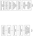
- Fig. 6 is a flow chart showing steps performed from a perspective of the network.
- the network receives a request for a first service with first and additional QoS description from a UE.
- the network stores the additional QoS description and establishes the first service based on the first QoS descriptions.
- the network receives a request for a second service with second QoS descriptions from the UE.
- the network determines that the first service would benefit from QoS based at least in parts on the second QoS descriptions which parts are contained in the additional QoS description.
- the network establishes the second service according to the second QoS descriptions and modifies the first service based at least in parts on the second QoS descriptions.
- the invention is particularly beneficial when the QoS setting is associated with a session and service continuity (SSC) mode as described above.
- SSC session and service continuity
Landscapes
- Engineering & Computer Science (AREA)
- Computer Networks & Wireless Communication (AREA)
- Signal Processing (AREA)
- Mobile Radio Communication Systems (AREA)
Claims (15)
- Verfahren zum Bereitstellen einer Dienstgüteeinstellung für eine erste Anwendung (14), die auf einer Benutzergerätvorrichtung (10), UE, betrieben wird, wobei die erste Anwendung eine Kommunikation zwischen der UE und einer Basisstation eines Kommunikationsnetzwerks beinhaltet, wobei das Verfahren umfasst:
Bestimmen einer ersten Dienstgüteeinstellung, QoS1, für die erste Anwendung, die von einer ersten Paketdateneinheits-, PDU-, Sitzung bedient wird, wobei die erste Dienstgüteeinstellung eine Mindestdienstanforderung umfasst, wobei das Verfahren weiter umfasst:Bestimmen, ob die erste Anwendung von einer Dienstgüteeinstellung profitieren könnte, die höher ist als die erste Dienstgüteeinstellung, und wenn ja, Speichern dieser Information entweder in der UE oder im Netzwerk; undnach Einleitung einer zweiten Anwendung (14) in der UE, die eine Kommunikation zwischen der UE und der Basisstation beinhaltet und durch eine zweite PDU-Sitzung bedient wird, wobei die zweite Anwendung eine zweite Dienstgüteeinstellung, QoS2, erfordert, die höher ist als die erste Dienstgüteeinstellung, Umschalten eines Paketflusses der ersten Anwendung auf die zweite PDU-Sitzung nur dann, wenn aus der gespeicherten Information bestimmt worden ist, dass die erste Anwendung von der höheren Dienstgüteeinstellung der zweiten PDU-Sitzung profitieren würde. - Verfahren nach Anspruch 1, wobei die Information in der UE gespeichert ist.
- Verfahren nach Anspruch 1, wobei die Information in einer Netzwerkeinheit des Kommunikationsnetzwerks gespeichert ist.
- Verfahren nach einem vorstehenden Anspruch, wobei die Information in Form einer Flag-Einstellung vorliegt.
- Verfahren nach einem der Ansprüche 1 bis 3, wobei die Information mindestens einen Parameter für die Kommunikation beinhaltet.
- Verfahren nach Anspruch 5, wobei der mindestens eine Parameter ein Parameter ist, der aus einer Liste ausgewählt ist, die einen IP-Adressbewahrungsgrad, einen Dienstkontinuitätsgrad und einen Datenverlustgrad umfasst.
- Verfahren nach einem vorstehenden Anspruch, wobei die erste Dienstgüteeinstellung von einer Netzwerkeinheit des Kommunikationsnetzwerks geändert wird.
- Verfahren nach einem der Ansprüche 1 bis 6, wobei die erste Dienstgüteeinstellung durch die UE geändert wird.
- Verfahren nach einem vorstehenden Anspruch, wobei die Information als Teil einer Dienstanforderungsnachricht an die Basisstation übertragen wird.
- Verfahren nach einem der Ansprüche 1 bis 8, wobei die Information durch die Basisstation während einer Anforderung zum Sitzungsaufbau einer Paketdateneinheit übertragen wird.
- Verfahren nach Anspruch 1, wobei die erste Dienstgüteeinstellung einem ersten Sitzungs- und Dienstkontinuitäts-, SSC-, Modus zugeordnet ist und die zweite Dienstgüteeinstellung einem zweiten SSC-Modus zugeordnet ist, der sich vom ersten SSC-Modus unterscheidet, und der erste und der zweite SSC-Modus mindestens eines davon unterscheiden, ob sich eine für einen Dienst verwendete Netzwerkadresse ändern kann und/oder ob ein Konnektivitätsdienst vom Netzwerk freigegeben werden kann und/oder ob vor der Freigabe eines Konnektivitätsdienstes einer Anwendung ein neuer Konnektivitätsdienst für die Anwendung eingerichtet wird.
- Benutzergerätvorrichtung (10), UE, die angepasst ist, um eine erste Anwendung (14) und eine zweite Anwendung (14) auszuführen, und wobei sowohl die erste Anwendung als auch die zweite Anwendung eine Kommunikation zwischen der UE und einer Basisstation beinhalten, wobei die UE eingerichtet ist, um eine erste Dienstgüteeinstellung, QoS1, für die erste Anwendung zu bestimmen, die durch eine erste Paketdateneinheits-, PDU-, Sitzung bedient wird, wobei die erste Dienstqualitätseinstellung eine Mindestdienstanforderung umfasst, wobei die UE-Vorrichtung weiter eingerichtet ist, um zu bestimmen, ob die erste Anwendung von einer Dienstgüteeinstellung profitieren könnte, die höher ist als die erste Dienstgüteeinstellung, und wenn dies der Fall ist, diese Information zu speichern; und nach Einleitung der zweiten Anwendung, die von einer zweiten PDU-Sitzung bedient wird, wobei die zweite Anwendung eine zweite Dienstgüteeinstellung, QoS2, benötigt, die höher ist als die erste Dienstgüteeinstellung, um einen Paketfluss der ersten Anwendung nur dann auf die zweite PDU-Sitzung umzuschalten, wenn aus der gespeicherten Information bestimmt worden ist, dass die erste Anwendung von der höheren Dienstgüteeinstellung der zweiten PDU-Sitzung profitieren würde.
- UE nach Anspruch 12, wobei die Information in Form einer Flag-Einstellung vorliegt.
- UE nach Anspruch 12, wobei die Information mindestens einen Parameter für die Kommunikation mit der Basisstation beinhaltet.
- Netzwerkgerätvorrichtung, MMF, die angepasst ist, um mit einer Benutzergerätvorrichtung (10), UE, zu kommunizieren, die eine erste Anwendung (14) und eine zweite Anwendung (14) ausführt, die beide eine Kommunikation zwischen dem Netzwerk und der UE beinhalten, wobei die Netzwerkgerätvorrichtung angepasst ist, um von der UE eine erste Dienstgüteeinstellung, QoS1, für die erste Anwendung zu empfangen, die durch eine erste Paketdateneinheits-, PDU-, Sitzung bedient wird, wobei die erste Dienstgüteeinstellung eine Mindestdienstanforderung umfasst, und die Netzwerkgerätvorrichtung auch angepasst ist, um von der UE eine Information darüber zu empfangen, ob die erste Anwendung von einer Dienstgüteeinstellung profitieren könnte, die höher ist als die erste Dienstgüteeinstellung, und wenn dies der Fall ist, diese Information zu speichern; wobei die Netzwerkgerätvorrichtung weiter eingerichtet ist, um nach Einleitung der zweiten Anwendung, die von einer zweiten PDU-Sitzung bedient wird, die eine zweite Dienstgüteeinstellung, QoS2, erfordert, die höher ist als die erste Dienstgüteeinstellung, einen Paketfluss der ersten Anwendung nur dann auf die zweite PDU-Sitzung umzuschalten, wenn aus der gespeicherten Information bestimmt worden ist, dass die erste Anwendung von der höheren Dienstgüteeinstellung der zweiten PDU-Sitzung profitieren würde.
Applications Claiming Priority (2)
| Application Number | Priority Date | Filing Date | Title |
|---|---|---|---|
| EP16201137 | 2016-11-29 | ||
| PCT/EP2017/080744 WO2018099936A1 (en) | 2016-11-29 | 2017-11-29 | OPPORTUNISTIC QoS IMPLEMENTATION |
Publications (2)
| Publication Number | Publication Date |
|---|---|
| EP3549314A1 EP3549314A1 (de) | 2019-10-09 |
| EP3549314B1 true EP3549314B1 (de) | 2024-11-13 |
Family
ID=57460335
Family Applications (1)
| Application Number | Title | Priority Date | Filing Date |
|---|---|---|---|
| EP17803971.5A Active EP3549314B1 (de) | 2016-11-29 | 2017-11-29 | Opportunistische qos-implementierung |
Country Status (4)
| Country | Link |
|---|---|
| US (1) | US20190281492A1 (de) |
| EP (1) | EP3549314B1 (de) |
| RU (1) | RU2745773C2 (de) |
| WO (1) | WO2018099936A1 (de) |
Families Citing this family (8)
| Publication number | Priority date | Publication date | Assignee | Title |
|---|---|---|---|---|
| US10897507B2 (en) * | 2016-04-01 | 2021-01-19 | Qualcomm Incorporated | Mechanism to enable connectivity sessions and IP session establishment |
| CN110418328B (zh) * | 2018-04-28 | 2021-01-05 | 华为技术有限公司 | 一种通信方法及装置 |
| US11039369B2 (en) * | 2018-08-10 | 2021-06-15 | Mediatek Inc. | Handling 5G QoS rules on QoS operation errors |
| US12052638B2 (en) * | 2018-12-19 | 2024-07-30 | Telefonaktiebolaget Lm Ericsson (Publ) | Reporting of multicast MAC addresses |
| CN112243300B (zh) * | 2019-07-19 | 2022-11-08 | 中国移动通信有限公司研究院 | 连接建立方法及装置 |
| KR20220001295A (ko) * | 2020-06-29 | 2022-01-05 | 에스케이텔레콤 주식회사 | 기지국장치 및 기지국장치의 동작 방법 |
| US12348384B2 (en) * | 2021-06-01 | 2025-07-01 | Nokia Technologies Oy | Packet data unit session for machine learning exploration for wireless communication network optimization |
| US20250260636A1 (en) * | 2024-02-14 | 2025-08-14 | Dell Products L.P. | Predictive and enhanced dynamic quality of service tagging on transport layer |
Family Cites Families (4)
| Publication number | Priority date | Publication date | Assignee | Title |
|---|---|---|---|---|
| US8139598B2 (en) * | 2005-03-21 | 2012-03-20 | Telefonaktiebolaget L M Ericsson (Publ) | Automatic QoS configuration |
| US20080132268A1 (en) | 2006-12-01 | 2008-06-05 | Cingular Wireless Ii, Llc | Dynamic quality of service adaptation in packet data communications |
| EP2592864A1 (de) * | 2011-11-10 | 2013-05-15 | Alcatel Lucent | Dienstverbindungsherstellung |
| US9055554B2 (en) * | 2012-12-12 | 2015-06-09 | At&T Intellectual Property I, L.P. | Management of voice communications over long term evolution networks |
-
2017
- 2017-11-29 EP EP17803971.5A patent/EP3549314B1/de active Active
- 2017-11-29 RU RU2019120265A patent/RU2745773C2/ru active
- 2017-11-29 US US16/345,509 patent/US20190281492A1/en not_active Abandoned
- 2017-11-29 WO PCT/EP2017/080744 patent/WO2018099936A1/en not_active Ceased
Also Published As
| Publication number | Publication date |
|---|---|
| EP3549314A1 (de) | 2019-10-09 |
| WO2018099936A1 (en) | 2018-06-07 |
| RU2019120265A3 (de) | 2021-01-13 |
| RU2745773C2 (ru) | 2021-03-31 |
| US20190281492A1 (en) | 2019-09-12 |
| RU2019120265A (ru) | 2021-01-11 |
Similar Documents
| Publication | Publication Date | Title |
|---|---|---|
| US12376001B2 (en) | Port information of time sensitive network bridge | |
| US12177939B2 (en) | Group communication session inactivity notification | |
| US12108470B2 (en) | Application triggering for a wireless device | |
| CA3151141C (en) | Policy control for multiple accesses | |
| US11477693B2 (en) | Establishing a session with a user plane function supporting uplink classifier functionality | |
| EP3549314B1 (de) | Opportunistische qos-implementierung | |
| US20220124870A1 (en) | Network Initiated UPF Sessions Transfer | |
| US12127127B2 (en) | Base station handling of transitioning wireless device to inactive state | |
| CN114556992B (zh) | 时间敏感联网桥的标识方法 | |
| US20250330888A1 (en) | Edge Computing Session Management | |
| US11129215B2 (en) | Location based selection of localized proxy application server | |
| KR20230129356A (ko) | 5g 로컬 서비스를 위한 서비스 요청 방법 | |
| KR20210112380A (ko) | 시간 민감성 네트워킹을 위한 제어 평면 기반 구성 | |
| WO2021092561A1 (en) | Session management for a network slice | |
| KR20210142725A (ko) | 코어 페이징 처리 | |
| US12101740B2 (en) | Signaling delivery in a wireless network | |
| CN115735371A (zh) | 网络切片特定认证和授权 | |
| KR20190004220A (ko) | 5g 단말 서비스 연속성 관리를 위한 upf 장치 재배치 방법 | |
| KR20140045990A (ko) | Lte/epc 네트워크들 내에서 pdn 연결들을 관리하기 위한 메커니즘 |
Legal Events
| Date | Code | Title | Description |
|---|---|---|---|
| STAA | Information on the status of an ep patent application or granted ep patent |
Free format text: STATUS: UNKNOWN |
|
| STAA | Information on the status of an ep patent application or granted ep patent |
Free format text: STATUS: THE INTERNATIONAL PUBLICATION HAS BEEN MADE |
|
| PUAI | Public reference made under article 153(3) epc to a published international application that has entered the european phase |
Free format text: ORIGINAL CODE: 0009012 |
|
| STAA | Information on the status of an ep patent application or granted ep patent |
Free format text: STATUS: REQUEST FOR EXAMINATION WAS MADE |
|
| 17P | Request for examination filed |
Effective date: 20190627 |
|
| AK | Designated contracting states |
Kind code of ref document: A1 Designated state(s): AL AT BE BG CH CY CZ DE DK EE ES FI FR GB GR HR HU IE IS IT LI LT LU LV MC MK MT NL NO PL PT RO RS SE SI SK SM TR |
|
| AX | Request for extension of the european patent |
Extension state: BA ME |
|
| DAV | Request for validation of the european patent (deleted) | ||
| DAX | Request for extension of the european patent (deleted) | ||
| STAA | Information on the status of an ep patent application or granted ep patent |
Free format text: STATUS: EXAMINATION IS IN PROGRESS |
|
| 17Q | First examination report despatched |
Effective date: 20200724 |
|
| REG | Reference to a national code |
Ref country code: DE Ref legal event code: R079 Ref document number: 602017086122 Country of ref document: DE Free format text: PREVIOUS MAIN CLASS: H04L0012833000 Ipc: H04L0047240000 |
|
| GRAP | Despatch of communication of intention to grant a patent |
Free format text: ORIGINAL CODE: EPIDOSNIGR1 |
|
| STAA | Information on the status of an ep patent application or granted ep patent |
Free format text: STATUS: GRANT OF PATENT IS INTENDED |
|
| RIC1 | Information provided on ipc code assigned before grant |
Ipc: H04W 28/02 20090101ALN20230710BHEP Ipc: H04L 47/2475 20220101ALI20230710BHEP Ipc: H04L 47/24 20220101AFI20230710BHEP |
|
| INTG | Intention to grant announced |
Effective date: 20230808 |
|
| GRAJ | Information related to disapproval of communication of intention to grant by the applicant or resumption of examination proceedings by the epo deleted |
Free format text: ORIGINAL CODE: EPIDOSDIGR1 |
|
| STAA | Information on the status of an ep patent application or granted ep patent |
Free format text: STATUS: EXAMINATION IS IN PROGRESS |
|
| GRAP | Despatch of communication of intention to grant a patent |
Free format text: ORIGINAL CODE: EPIDOSNIGR1 |
|
| STAA | Information on the status of an ep patent application or granted ep patent |
Free format text: STATUS: GRANT OF PATENT IS INTENDED |
|
| INTC | Intention to grant announced (deleted) | ||
| RIC1 | Information provided on ipc code assigned before grant |
Ipc: H04W 28/02 20090101ALN20231214BHEP Ipc: H04L 47/2475 20220101ALI20231214BHEP Ipc: H04L 47/24 20220101AFI20231214BHEP |
|
| INTG | Intention to grant announced |
Effective date: 20240105 |
|
| GRAS | Grant fee paid |
Free format text: ORIGINAL CODE: EPIDOSNIGR3 |
|
| GRAA | (expected) grant |
Free format text: ORIGINAL CODE: 0009210 |
|
| STAA | Information on the status of an ep patent application or granted ep patent |
Free format text: STATUS: THE PATENT HAS BEEN GRANTED |
|
| AK | Designated contracting states |
Kind code of ref document: B1 Designated state(s): AL AT BE BG CH CY CZ DE DK EE ES FI FR GB GR HR HU IE IS IT LI LT LU LV MC MK MT NL NO PL PT RO RS SE SI SK SM TR |
|
| REG | Reference to a national code |
Ref country code: GB Ref legal event code: FG4D |
|
| REG | Reference to a national code |
Ref country code: CH Ref legal event code: EP |
|
| REG | Reference to a national code |
Ref country code: IE Ref legal event code: FG4D |
|
| REG | Reference to a national code |
Ref country code: DE Ref legal event code: R096 Ref document number: 602017086122 Country of ref document: DE |
|
| P01 | Opt-out of the competence of the unified patent court (upc) registered |
Free format text: CASE NUMBER: APP_3633/2025 Effective date: 20250122 |
|
| REG | Reference to a national code |
Ref country code: LT Ref legal event code: MG9D |
|
| REG | Reference to a national code |
Ref country code: NL Ref legal event code: MP Effective date: 20241113 |
|
| PG25 | Lapsed in a contracting state [announced via postgrant information from national office to epo] |
Ref country code: PT Free format text: LAPSE BECAUSE OF FAILURE TO SUBMIT A TRANSLATION OF THE DESCRIPTION OR TO PAY THE FEE WITHIN THE PRESCRIBED TIME-LIMIT Effective date: 20250313 Ref country code: HR Free format text: LAPSE BECAUSE OF FAILURE TO SUBMIT A TRANSLATION OF THE DESCRIPTION OR TO PAY THE FEE WITHIN THE PRESCRIBED TIME-LIMIT Effective date: 20241113 Ref country code: IS Free format text: LAPSE BECAUSE OF FAILURE TO SUBMIT A TRANSLATION OF THE DESCRIPTION OR TO PAY THE FEE WITHIN THE PRESCRIBED TIME-LIMIT Effective date: 20250313 |
|
| PG25 | Lapsed in a contracting state [announced via postgrant information from national office to epo] |
Ref country code: NL Free format text: LAPSE BECAUSE OF FAILURE TO SUBMIT A TRANSLATION OF THE DESCRIPTION OR TO PAY THE FEE WITHIN THE PRESCRIBED TIME-LIMIT Effective date: 20241113 Ref country code: FI Free format text: LAPSE BECAUSE OF FAILURE TO SUBMIT A TRANSLATION OF THE DESCRIPTION OR TO PAY THE FEE WITHIN THE PRESCRIBED TIME-LIMIT Effective date: 20241113 |
|
| REG | Reference to a national code |
Ref country code: AT Ref legal event code: MK05 Ref document number: 1742513 Country of ref document: AT Kind code of ref document: T Effective date: 20241113 |
|
| PG25 | Lapsed in a contracting state [announced via postgrant information from national office to epo] |
Ref country code: BG Free format text: LAPSE BECAUSE OF FAILURE TO SUBMIT A TRANSLATION OF THE DESCRIPTION OR TO PAY THE FEE WITHIN THE PRESCRIBED TIME-LIMIT Effective date: 20241113 |
|
| PG25 | Lapsed in a contracting state [announced via postgrant information from national office to epo] |
Ref country code: ES Free format text: LAPSE BECAUSE OF FAILURE TO SUBMIT A TRANSLATION OF THE DESCRIPTION OR TO PAY THE FEE WITHIN THE PRESCRIBED TIME-LIMIT Effective date: 20241113 |
|
| PG25 | Lapsed in a contracting state [announced via postgrant information from national office to epo] |
Ref country code: NO Free format text: LAPSE BECAUSE OF FAILURE TO SUBMIT A TRANSLATION OF THE DESCRIPTION OR TO PAY THE FEE WITHIN THE PRESCRIBED TIME-LIMIT Effective date: 20250213 |
|
| PG25 | Lapsed in a contracting state [announced via postgrant information from national office to epo] |
Ref country code: LV Free format text: LAPSE BECAUSE OF FAILURE TO SUBMIT A TRANSLATION OF THE DESCRIPTION OR TO PAY THE FEE WITHIN THE PRESCRIBED TIME-LIMIT Effective date: 20241113 Ref country code: AT Free format text: LAPSE BECAUSE OF FAILURE TO SUBMIT A TRANSLATION OF THE DESCRIPTION OR TO PAY THE FEE WITHIN THE PRESCRIBED TIME-LIMIT Effective date: 20241113 Ref country code: GR Free format text: LAPSE BECAUSE OF FAILURE TO SUBMIT A TRANSLATION OF THE DESCRIPTION OR TO PAY THE FEE WITHIN THE PRESCRIBED TIME-LIMIT Effective date: 20250214 |
|
| PG25 | Lapsed in a contracting state [announced via postgrant information from national office to epo] |
Ref country code: PL Free format text: LAPSE BECAUSE OF FAILURE TO SUBMIT A TRANSLATION OF THE DESCRIPTION OR TO PAY THE FEE WITHIN THE PRESCRIBED TIME-LIMIT Effective date: 20241113 |
|
| PG25 | Lapsed in a contracting state [announced via postgrant information from national office to epo] |
Ref country code: RS Free format text: LAPSE BECAUSE OF FAILURE TO SUBMIT A TRANSLATION OF THE DESCRIPTION OR TO PAY THE FEE WITHIN THE PRESCRIBED TIME-LIMIT Effective date: 20250213 |
|
| REG | Reference to a national code |
Ref country code: DE Ref legal event code: R119 Ref document number: 602017086122 Country of ref document: DE |
|
| REG | Reference to a national code |
Ref country code: CH Ref legal event code: PL |
|
| PG25 | Lapsed in a contracting state [announced via postgrant information from national office to epo] |
Ref country code: SM Free format text: LAPSE BECAUSE OF FAILURE TO SUBMIT A TRANSLATION OF THE DESCRIPTION OR TO PAY THE FEE WITHIN THE PRESCRIBED TIME-LIMIT Effective date: 20241113 |
|
| PG25 | Lapsed in a contracting state [announced via postgrant information from national office to epo] |
Ref country code: DK Free format text: LAPSE BECAUSE OF FAILURE TO SUBMIT A TRANSLATION OF THE DESCRIPTION OR TO PAY THE FEE WITHIN THE PRESCRIBED TIME-LIMIT Effective date: 20241113 |
|
| PG25 | Lapsed in a contracting state [announced via postgrant information from national office to epo] |
Ref country code: LU Free format text: LAPSE BECAUSE OF NON-PAYMENT OF DUE FEES Effective date: 20241129 |
|
| REG | Reference to a national code |
Ref country code: CH Ref legal event code: PL |
|
| PG25 | Lapsed in a contracting state [announced via postgrant information from national office to epo] |
Ref country code: EE Free format text: LAPSE BECAUSE OF FAILURE TO SUBMIT A TRANSLATION OF THE DESCRIPTION OR TO PAY THE FEE WITHIN THE PRESCRIBED TIME-LIMIT Effective date: 20241113 |
|
| PG25 | Lapsed in a contracting state [announced via postgrant information from national office to epo] |
Ref country code: CH Free format text: LAPSE BECAUSE OF NON-PAYMENT OF DUE FEES Effective date: 20241130 |
|
| PG25 | Lapsed in a contracting state [announced via postgrant information from national office to epo] |
Ref country code: RO Free format text: LAPSE BECAUSE OF FAILURE TO SUBMIT A TRANSLATION OF THE DESCRIPTION OR TO PAY THE FEE WITHIN THE PRESCRIBED TIME-LIMIT Effective date: 20241113 |
|
| PG25 | Lapsed in a contracting state [announced via postgrant information from national office to epo] |
Ref country code: SK Free format text: LAPSE BECAUSE OF FAILURE TO SUBMIT A TRANSLATION OF THE DESCRIPTION OR TO PAY THE FEE WITHIN THE PRESCRIBED TIME-LIMIT Effective date: 20241113 |
|
| PG25 | Lapsed in a contracting state [announced via postgrant information from national office to epo] |
Ref country code: CZ Free format text: LAPSE BECAUSE OF FAILURE TO SUBMIT A TRANSLATION OF THE DESCRIPTION OR TO PAY THE FEE WITHIN THE PRESCRIBED TIME-LIMIT Effective date: 20241113 |
|
| PG25 | Lapsed in a contracting state [announced via postgrant information from national office to epo] |
Ref country code: IT Free format text: LAPSE BECAUSE OF FAILURE TO SUBMIT A TRANSLATION OF THE DESCRIPTION OR TO PAY THE FEE WITHIN THE PRESCRIBED TIME-LIMIT Effective date: 20241113 |
|
| REG | Reference to a national code |
Ref country code: BE Ref legal event code: MM Effective date: 20241130 |
|
| PG25 | Lapsed in a contracting state [announced via postgrant information from national office to epo] |
Ref country code: SE Free format text: LAPSE BECAUSE OF FAILURE TO SUBMIT A TRANSLATION OF THE DESCRIPTION OR TO PAY THE FEE WITHIN THE PRESCRIBED TIME-LIMIT Effective date: 20241113 |
|
| PG25 | Lapsed in a contracting state [announced via postgrant information from national office to epo] |
Ref country code: MC Free format text: LAPSE BECAUSE OF FAILURE TO SUBMIT A TRANSLATION OF THE DESCRIPTION OR TO PAY THE FEE WITHIN THE PRESCRIBED TIME-LIMIT Effective date: 20241113 |
|
| PLBE | No opposition filed within time limit |
Free format text: ORIGINAL CODE: 0009261 |
|
| STAA | Information on the status of an ep patent application or granted ep patent |
Free format text: STATUS: NO OPPOSITION FILED WITHIN TIME LIMIT |
|
| PG25 | Lapsed in a contracting state [announced via postgrant information from national office to epo] |
Ref country code: DE Free format text: LAPSE BECAUSE OF NON-PAYMENT OF DUE FEES Effective date: 20250603 |
|
| PG25 | Lapsed in a contracting state [announced via postgrant information from national office to epo] |
Ref country code: BE Free format text: LAPSE BECAUSE OF NON-PAYMENT OF DUE FEES Effective date: 20241130 |
|
| PG25 | Lapsed in a contracting state [announced via postgrant information from national office to epo] |
Ref country code: FR Free format text: LAPSE BECAUSE OF NON-PAYMENT OF DUE FEES Effective date: 20250113 |
|
| 26N | No opposition filed |
Effective date: 20250814 |
|
| PG25 | Lapsed in a contracting state [announced via postgrant information from national office to epo] |
Ref country code: IE Free format text: LAPSE BECAUSE OF NON-PAYMENT OF DUE FEES Effective date: 20241129 |
|
| GBPC | Gb: european patent ceased through non-payment of renewal fee |
Effective date: 20250213 |
|
| PG25 | Lapsed in a contracting state [announced via postgrant information from national office to epo] |
Ref country code: GB Free format text: LAPSE BECAUSE OF NON-PAYMENT OF DUE FEES Effective date: 20250213 |
|
| PG25 | Lapsed in a contracting state [announced via postgrant information from national office to epo] |
Ref country code: HU Free format text: LAPSE BECAUSE OF FAILURE TO SUBMIT A TRANSLATION OF THE DESCRIPTION OR TO PAY THE FEE WITHIN THE PRESCRIBED TIME-LIMIT; INVALID AB INITIO Effective date: 20171129 |
|
| PG25 | Lapsed in a contracting state [announced via postgrant information from national office to epo] |
Ref country code: CY Free format text: LAPSE BECAUSE OF FAILURE TO SUBMIT A TRANSLATION OF THE DESCRIPTION OR TO PAY THE FEE WITHIN THE PRESCRIBED TIME-LIMIT; INVALID AB INITIO Effective date: 20171129 |