EP3548725B1 - Combustion cylinder - Google Patents
Combustion cylinder Download PDFInfo
- Publication number
- EP3548725B1 EP3548725B1 EP17804552.2A EP17804552A EP3548725B1 EP 3548725 B1 EP3548725 B1 EP 3548725B1 EP 17804552 A EP17804552 A EP 17804552A EP 3548725 B1 EP3548725 B1 EP 3548725B1
- Authority
- EP
- European Patent Office
- Prior art keywords
- piston
- piston crown
- combustion cylinder
- central axis
- bowl
- Prior art date
- Legal status (The legal status is an assumption and is not a legal conclusion. Google has not performed a legal analysis and makes no representation as to the accuracy of the status listed.)
- Active
Links
Images



Classifications
-
- F—MECHANICAL ENGINEERING; LIGHTING; HEATING; WEAPONS; BLASTING
- F02—COMBUSTION ENGINES; HOT-GAS OR COMBUSTION-PRODUCT ENGINE PLANTS
- F02F—CYLINDERS, PISTONS OR CASINGS, FOR COMBUSTION ENGINES; ARRANGEMENTS OF SEALINGS IN COMBUSTION ENGINES
- F02F3/00—Pistons
- F02F3/26—Pistons having combustion chamber in piston head
-
- F—MECHANICAL ENGINEERING; LIGHTING; HEATING; WEAPONS; BLASTING
- F02—COMBUSTION ENGINES; HOT-GAS OR COMBUSTION-PRODUCT ENGINE PLANTS
- F02B—INTERNAL-COMBUSTION PISTON ENGINES; COMBUSTION ENGINES IN GENERAL
- F02B23/00—Other engines characterised by special shape or construction of combustion chambers to improve operation
- F02B23/02—Other engines characterised by special shape or construction of combustion chambers to improve operation with compression ignition
- F02B23/06—Other engines characterised by special shape or construction of combustion chambers to improve operation with compression ignition the combustion space being arranged in working piston
- F02B23/0672—Omega-piston bowl, i.e. the combustion space having a central projection pointing towards the cylinder head and the surrounding wall being inclined towards the cylinder center axis
-
- F—MECHANICAL ENGINEERING; LIGHTING; HEATING; WEAPONS; BLASTING
- F02—COMBUSTION ENGINES; HOT-GAS OR COMBUSTION-PRODUCT ENGINE PLANTS
- F02B—INTERNAL-COMBUSTION PISTON ENGINES; COMBUSTION ENGINES IN GENERAL
- F02B23/00—Other engines characterised by special shape or construction of combustion chambers to improve operation
- F02B23/02—Other engines characterised by special shape or construction of combustion chambers to improve operation with compression ignition
- F02B23/06—Other engines characterised by special shape or construction of combustion chambers to improve operation with compression ignition the combustion space being arranged in working piston
-
- F—MECHANICAL ENGINEERING; LIGHTING; HEATING; WEAPONS; BLASTING
- F02—COMBUSTION ENGINES; HOT-GAS OR COMBUSTION-PRODUCT ENGINE PLANTS
- F02B—INTERNAL-COMBUSTION PISTON ENGINES; COMBUSTION ENGINES IN GENERAL
- F02B23/00—Other engines characterised by special shape or construction of combustion chambers to improve operation
- F02B23/02—Other engines characterised by special shape or construction of combustion chambers to improve operation with compression ignition
- F02B23/06—Other engines characterised by special shape or construction of combustion chambers to improve operation with compression ignition the combustion space being arranged in working piston
- F02B23/0645—Details related to the fuel injector or the fuel spray
-
- F—MECHANICAL ENGINEERING; LIGHTING; HEATING; WEAPONS; BLASTING
- F02—COMBUSTION ENGINES; HOT-GAS OR COMBUSTION-PRODUCT ENGINE PLANTS
- F02B—INTERNAL-COMBUSTION PISTON ENGINES; COMBUSTION ENGINES IN GENERAL
- F02B23/00—Other engines characterised by special shape or construction of combustion chambers to improve operation
- F02B23/02—Other engines characterised by special shape or construction of combustion chambers to improve operation with compression ignition
- F02B23/06—Other engines characterised by special shape or construction of combustion chambers to improve operation with compression ignition the combustion space being arranged in working piston
- F02B23/0645—Details related to the fuel injector or the fuel spray
- F02B23/0669—Details related to the fuel injector or the fuel spray having multiple fuel spray jets per injector nozzle
-
- F—MECHANICAL ENGINEERING; LIGHTING; HEATING; WEAPONS; BLASTING
- F02—COMBUSTION ENGINES; HOT-GAS OR COMBUSTION-PRODUCT ENGINE PLANTS
- F02B—INTERNAL-COMBUSTION PISTON ENGINES; COMBUSTION ENGINES IN GENERAL
- F02B23/00—Other engines characterised by special shape or construction of combustion chambers to improve operation
- F02B23/02—Other engines characterised by special shape or construction of combustion chambers to improve operation with compression ignition
- F02B23/06—Other engines characterised by special shape or construction of combustion chambers to improve operation with compression ignition the combustion space being arranged in working piston
- F02B23/0678—Unconventional, complex or non-rotationally symmetrical shapes of the combustion space, e.g. flower like, having special shapes related to the orientation of the fuel spray jets
- F02B23/0693—Unconventional, complex or non-rotationally symmetrical shapes of the combustion space, e.g. flower like, having special shapes related to the orientation of the fuel spray jets the combustion space consisting of step-wise widened multiple zones of different depth
-
- F—MECHANICAL ENGINEERING; LIGHTING; HEATING; WEAPONS; BLASTING
- F02—COMBUSTION ENGINES; HOT-GAS OR COMBUSTION-PRODUCT ENGINE PLANTS
- F02B—INTERNAL-COMBUSTION PISTON ENGINES; COMBUSTION ENGINES IN GENERAL
- F02B23/00—Other engines characterised by special shape or construction of combustion chambers to improve operation
- F02B23/02—Other engines characterised by special shape or construction of combustion chambers to improve operation with compression ignition
- F02B23/06—Other engines characterised by special shape or construction of combustion chambers to improve operation with compression ignition the combustion space being arranged in working piston
- F02B23/0696—W-piston bowl, i.e. the combustion space having a central projection pointing towards the cylinder head and the surrounding wall being inclined towards the cylinder wall
-
- F—MECHANICAL ENGINEERING; LIGHTING; HEATING; WEAPONS; BLASTING
- F02—COMBUSTION ENGINES; HOT-GAS OR COMBUSTION-PRODUCT ENGINE PLANTS
- F02B—INTERNAL-COMBUSTION PISTON ENGINES; COMBUSTION ENGINES IN GENERAL
- F02B2275/00—Other engines, components or details, not provided for in other groups of this subclass
- F02B2275/14—Direct injection into combustion chamber
-
- Y—GENERAL TAGGING OF NEW TECHNOLOGICAL DEVELOPMENTS; GENERAL TAGGING OF CROSS-SECTIONAL TECHNOLOGIES SPANNING OVER SEVERAL SECTIONS OF THE IPC; TECHNICAL SUBJECTS COVERED BY FORMER USPC CROSS-REFERENCE ART COLLECTIONS [XRACs] AND DIGESTS
- Y02—TECHNOLOGIES OR APPLICATIONS FOR MITIGATION OR ADAPTATION AGAINST CLIMATE CHANGE
- Y02T—CLIMATE CHANGE MITIGATION TECHNOLOGIES RELATED TO TRANSPORTATION
- Y02T10/00—Road transport of goods or passengers
- Y02T10/10—Internal combustion engine [ICE] based vehicles
- Y02T10/12—Improving ICE efficiencies
Definitions
- This disclosure relates generally to combustion cylinders with piston bowls for internal combustion engines
- Combustion characteristics within a combustion chamber of an engine may be influenced by, among other things, shape of the combustion chamber and injection characteristics of fuel injected into the combustion chamber. In this way, factors such as fuel combustion efficiency and the composition of combustion emissions may be influenced. Composition of combustion emissions includes an extent to which combustion produces NO x and particulate matter, such as soot.
- the shape of a combustion bowl may be dictated by, among other things, whether it is intended for the fuel to target a feature of the piston bowl in order to distribute fuel vapour within the bowl (known as a targeted piston bowl) or it is intended for the fuel to be guided by the bowl without making a targeted impact (known as a spray guided piston bowl). Whether a piston bowl is employed for targeted or spray guided use is also governed by the manner of fuel injection within the cylinder. Injection behaviour may be governed, among other things, by the number and arrangement of injection orifices, including the angle of such orifices relative to the combustion cylinder. The present disclosure relates to spray guided piston bowls.
- a swirl ratio that being defined as angular rotational speed of trapped gases within the cylinder about the cylinder axis divided by engine speed. This may be desirable in order to promote efficient mixing of the fuel and air and limit the penetration of the combusting gases.
- the present disclosure relates to spray guided piston bowls developed from larger prior art spray guided piston bowls (as illustrated in Figures 3 and 4 ).
- the piston bowls of the present disclosure may be suitable for a smaller diameter combustion cylinder with high efficiency and low emissions.
- US2013239925 discloses a piston for a compression ignition internal combustion engine that includes a piston body having a combustion face defining a combustion bowl, and the combustion face including a compound bowl surface and a compound rim surface.
- the combustion face is profiled to balance a combustion efficiency property of the piston with emissions properties of the piston.
- a ratio of a diameter of the combustion bowl to a diameter of the cylinder bowl bore is from 0.68 to 0.74.
- Other dimensional and proportional features of the piston support low smoke and NOx production during operation.
- Figure 1 shows a cross section through a cylinder 100 of an internal combustion engine together with related features.
- the cylinder comprises an internal bore 101.
- the internal bore 101 accommodates a piston 110.
- the piston 110 is coaxial with the internal bore 101 of the cylinder 100 such that the piston 110 is movable relative to the cylinder 100 in an axial direction.
- the fuel injector 130 may be located coaxially with the internal bore 101 of the cylinder such that fuel injected by the fuel injector 130 may enter the internal bore 101 at the axis.
- the fuel injector 130 may comprise a fuel injector head (not shown) for distributing fuel in accordance with a desired geometrical arrangement.
- the piston 110 comprises a piston crown 120 and a piston body (not shown but located underneath the piston crown 120 in the orientation of Figure 1 ).
- the piston crown 120 is at a head end of the piston 110 such that the piston crown 120 of the piston 110 faces the fuel injector 130.
- the cylinder 100 may further comprise an oxidant inlet 140 for selectively allowing inlet of an oxidant, such as air, to facilitate combustion and an exhaust outlet 150 for selectively allowing release of combustion products from the cylinder 100.
- the oxidant inlet 140 and the exhaust outlet 150 may be located at the top end 102 of the cylinder 100 adjacent the fuel injector 130.
- An intake passage 90 is in fluid communication with, and configured to supply air to, cylinder 100, and an exhaust passage 92 is also in fluid communication with, and conveys combustion products out of, cylinder 100.
- Intake valves and exhaust valves are not shown in Figure 1 , but will typically be provided in a conventional manner.
- An exhaust gas recirculation loop 94 may connect passages 90 and 92, and may have an exhaust recirculation control valve 96 and an exhaust gas cooler 98 positioned therein.
- the piston 110 is shown relative to the cylinder 110 at a position in its oscillating cycle that is closest to the top end 102 of the cylinder 100.
- the piston crown 120 has an axial direction that sits vertically in the orientation of Figure 1 and a radial direction that sits horizontally in the orientation of Figure 1 .
- the piston crown 120 is rotationally symmetrical about a central axis 290 in the axial direction.
- the central axis 290 of the piston crown 120 is, when in situ in the cylinder, coaxial with a central axis of the fuel injector 130.
- Figure 2 shows the piston of Figure 1 in isolation from the cylinder 100.
- the piston crown 120 comprises an annular surface 201 at a first end 280 of the piston crown 120 in the axial direction that, when in situ in the cylinder 100, faces the fuel injector 130.
- the annular surface 201 may be radially furthest from the central axis 290.
- the piston crown 120 further comprises a piston bowl 210 located radially within the annular surface 201 and recessed relative to the first end 280 of the piston crown.
- the raised floor 220 comprises a frusto-conical surface 221 tapering in a direction of the first end 280 of the piston crown towards a spherical cap 222 that caps the frusto-conical surface 221.
- An angle of the frusto-conical surface 221 relative to a plane orthogonal to the axis 290 is the same as an angle of the lowest portion of the spherical cap 222 so as to avoid any surface discontinuity at the interface between the frusto-conical surface 221 and the spherical cap 222.
- a diameter of the frusto-conical surface 221 at its smaller end is the same as a widest dimension of the spherical cap 222.
- the diameter of the frusto-conical surface 221 is aligned with the widest dimension of the spherical cap 222.
- the arcuate surface 230 when the piston 120 is viewed in diametric cross section, has a single radius between where the arcuate surface 230 interfaces with a radially outermost end of the frusto-conical surface 221 and where the arcuate surface 230 interfaces with the circumferential surface 235 parallel to the axis of the piston bowl 210.
- the lip chamfer surface 240 that extends radially outwardly from the circumferential surface 235 and radially inwardly from the annular surface 201 tapers such that a widest portion of the piston bowl 210 is at its entrance. Its entrance is location in a plane shared with the annular surface 201 at the first end of the piston crown 280.
- the cylinder 100 in which the piston 120 reciprocates has a radius D 1 such that an overall diameter of the cylinder 100 is 2D 1 .
- a diameter of a largest part of the piston 120 is smaller than 2D 1 .
- the circumferential surface 235 of the piston 120 has a radius D 2 such that the diameter of the circumferential surface 235 is 2D 2 .
- the lip chamfer surface 240 has a radial dimension D 8 .
- a diameter of the piston bowl throat in the plane of the annular surface 201 is 2(D 2 + Ds).
- a dimension along the axis of the piston between the plane of the annular surface 201 and a part of the spherical cap closest thereto is D 5 .
- An angle between opposing straight line portions (that is, when viewed in diametric cross-section) of the frusto-conical surface 221 is A 1 .
- an angle between axes of injector orifices configured to inject fuel into the cylinder is A 2 .
- a radius of curvature between the annular surface 201 and the lip chamfer surface 240 is R 1 , and in the claimed embodiments R 1 is zero.
- a radius of curvature between the lip chamfer surface 240 and the circumferential surface 235 is R 2 .
- a radius of curvature of the arcuate surface 230 is R 3 .
- a radius of curvature of the spherical cap 222 is R 5 .
- the radii of curvature R 1 , R 2 , R 4 and R 5 are those identifiable in diametric cross-section through the axis of the piston 120. It should be noted that, for clarity, the radii marked on the Figures are drawn to arbitrary lengths and do not relate in any way to the absolute length or to the relative length of the radii they represent.
- a dimension in an axial direction between the annular surface 201 and the origin of the radius R2 is D 4 .
- the lip chamfer surface 240 is a straight line between an inner end of the radii R 1 and an outer end of the radii R 2 , when viewed in diametric cross-section through the axis of the piston 120.
- An angle between the straight line of the lip chamber surface 240 and the annular surface 201 is A 4 . This is shown in more detail in Figure 5 , albeit highly schematically.
- the lip chamfer surface 240 is curved between an inner end of the radii R 1 and an outer end of the radii R 2 , when viewed in diametric cross-section through the axis of the piston 120.
- the radius of curvature of the lip chamfer surface 240 in such an arrangement is R 6 .
- R 6 This is shown in Figure 6 , albeit highly schematically, particularly since R 6 may be sufficiently large as not to be immediately identifiable at the scale shown in Figure 6 .
- An angle between a tangent to the radius R 6 and the annular surface 201 is A 4 (for clarity, the tangent and angle are not shown in Figure 6 ).
- the value A 4 may be between 19 ° and 21 °. In the case of the Figure 5 embodiment, the value A 4 is 20 °.
- Figures 1 , 2 and 5 show embodiments of the present disclosure
- Figure 6 shows an arrangement that falls outside the scope of the claims
- Figures 3 and 4 relate to prior art piston bowls.
- Figures 1 , 2 , 5 & 6 Figure 3 Figure 4 R 1 0 mm n/a n/a R 2 1.5 mm 1.5 mm 1.5 mm 1.5 mm R 3 10.5 mm 12 mm 12 mm R 5 10 mm 9.98 mm 10 mm R 6 n/a or > 30 mm n/a n/a A 1 125.7 degrees 125 degrees 125 degrees A 2 130 degrees 130 degrees 130 degrees A 2 minus A 1 4.3 degrees 5 degrees 5 degrees A 4 20 degrees n/a n/a D 1 (bore radius) 49 mm 52.5 mm 52.5 mm D 2 34.95 mm 38.3 mm 38.3 mm D 4 2.49 mm 1.5 mm 1.5 mm D 5 3.55 mm 4.81 mm 3.97 mm D 8 3.95 mm 0 mm 0 mm Number of injector orifices 6 6 6 Bowl volume 42.1 cm3 58.5 cm3 54.6 cm3 Compression ratio 17.0:1 16.5: 1 16.5:1 Swirl ratio 1.8 0.4
- fuel is injected into the combustion chamber from an injector 130 shown in Figures 1 and 7 .
- the injector 130 comprises a plurality of spray discharge orifices 131 through which fuel may be injected.
- the number of spray discharge orifices 131 is six (6).
- Each spray discharge orifice 131 has a central axis Q.
- Central axis Q passes through the centre point of each spray discharge orifice 131.
- each central axis Q may be transverse to a plane extending across each respective spray discharge orifice 131.
- each spray discharge passage has a longitudinal axis that is coincident with central axis Q of respective spray discharge orifice 131.
- Each respective spray discharge passage may extend along the central axis Q.
- each central axis Q may be normal to a plane extending across each respective inlet.
- Each central axis Q has an angle ⁇ relative to a central axis P of the injector 130 which is coincident with the central axis of the piston 290.
- each central axis Q may have an angle ⁇ of approximately 64.5 ° to 65.5 ° relative to the central axis P.
- each central axis Q has an angle ⁇ of 65 ° relative to the central axis P.
- Fuel injector 10 has a spray cone angle A 2 (see Figure 1 ) that is defined by angle 2 ⁇ (see Figure 7 ). Accordingly, in the comparative examples, fuel vapour from the plurality of spray discharge orifices 131 may be discharged with a spray cone angle of approximately 129 ° to 131 °. According to the claims, fuel vapour from the plurality of spray discharge orifices 131 is discharged with a spray cone angle of 130 °.
- Fuel may be discharged from the plurality of spray discharge orifices 131 at a flow rate of 680 to 720 cc/min. Fuel may be expelled from the plurality of spray discharge orifices 131 at a flow rate of 700 cc/min.
- a swirl ratio is defined as angular rotational speed about the cylinder axis.
- a swirl ratio of 1.8 is employed. This may promote efficient mixing of the fuel and air and avoid combustion products residing in specific areas that may affect engine durability.
- the lip chamfer surface 240 may be particularly beneficial in a piston of reduced size since it promotes distribution of fuel leaving the piston bowl. As distinct from the prior art embodiments of Figures 3 and 4 which have larger combustion volumes, the lip chamfer surface 240 of the embodiments of the present disclosure may encourage improved fuel distribution for improved thermal distribution and improved combustion efficiency, perhaps most particularly applicable in a combustion cylinder operating a fuel injector with a swirl ratio of approximately 1.8.
- Figure 8 provides a plot of soot against NO x for piston bowls in accordance with the disclosure (e.g. Figures 1 and 2 ) relative to piston bowls of the prior art (e.g. Figures 3 and 4 ).
- the piston bowl of the present disclosure provides lower soot than the piston bowl of the prior art, when using the same swirl ratio.
- Figure 9 provides a plot of flux versus injection timing and shows plots both for piston bowls in accordance with the prior art (e.g. Figures 3 and 4 ) and piston bowls of the present disclosure (e.g. Figures 1 and 2 ).
- the present disclosure relates to a spray guided piston bowl that may be applicable to a diesel engine for achieving improved fuel to air mixing that in turn results in more efficient combustion and reduced NO x and/or particulate emissions.
- the piston may be of aluminium.
- the engine may be based on a known larger engine with a reduced piston diameter and volume and adapted to improve efficiency and to target specific emissions outputs.
Landscapes
- Engineering & Computer Science (AREA)
- Chemical & Material Sciences (AREA)
- Combustion & Propulsion (AREA)
- Mechanical Engineering (AREA)
- General Engineering & Computer Science (AREA)
- Combustion Methods Of Internal-Combustion Engines (AREA)
Description
- This disclosure relates generally to combustion cylinders with piston bowls for internal combustion engines
- Increasing engine efficiency and reducing emissions is a desire of engine manufacturers and users alike.
- Combustion characteristics within a combustion chamber of an engine may be influenced by, among other things, shape of the combustion chamber and injection characteristics of fuel injected into the combustion chamber. In this way, factors such as fuel combustion efficiency and the composition of combustion emissions may be influenced. Composition of combustion emissions includes an extent to which combustion produces NOx and particulate matter, such as soot.
- An engine may have a combustion chamber bounded by an interior surface of a combustion cylinder and a top surface of a piston that reciprocates within the combustion cylinder. In such a combustion chamber, it is possible to influence combustion characteristics by altering the top surface of the piston that faces a fuel injector configured to inject fuel into the combustion cylinder. It is also possible to influence combustion characteristics by altering the distribution of fuel injected into the combustion chamber.
- It is known to provide a variety of different piston bowls within the top surface of the piston.
- The shape of a combustion bowl may be dictated by, among other things, whether it is intended for the fuel to target a feature of the piston bowl in order to distribute fuel vapour within the bowl (known as a targeted piston bowl) or it is intended for the fuel to be guided by the bowl without making a targeted impact (known as a spray guided piston bowl). Whether a piston bowl is employed for targeted or spray guided use is also governed by the manner of fuel injection within the cylinder. Injection behaviour may be governed, among other things, by the number and arrangement of injection orifices, including the angle of such orifices relative to the combustion cylinder. The present disclosure relates to spray guided piston bowls.
- Given increases in engine efficiency and changes to regulatory regimes, there may be a desire to produce smaller engines. However, for various reasons, it may not be appropriate simply to scale all dimensions of a combustion cylinder and piston. One reason for this may be that fuel injection behaviour may not be easily scalable and/or, to the extent that fuel injection behaviour may be scalable, it may be undesirable for other reasons.
- In producing smaller engines, it may be desirable to increase a swirl ratio, that being defined as angular rotational speed of trapped gases within the cylinder about the cylinder axis divided by engine speed. This may be desirable in order to promote efficient mixing of the fuel and air and limit the penetration of the combusting gases.
- The present disclosure relates to spray guided piston bowls developed from larger prior art spray guided piston bowls (as illustrated in
Figures 3 and4 ). The piston bowls of the present disclosure may be suitable for a smaller diameter combustion cylinder with high efficiency and low emissions. -
US2013239925 discloses a piston for a compression ignition internal combustion engine that includes a piston body having a combustion face defining a combustion bowl, and the combustion face including a compound bowl surface and a compound rim surface. The combustion face is profiled to balance a combustion efficiency property of the piston with emissions properties of the piston. A ratio of a diameter of the combustion bowl to a diameter of the cylinder bowl bore is from 0.68 to 0.74. Other dimensional and proportional features of the piston support low smoke and NOx production during operation. - Against this background, there is provided a combustion cylinder in accordance with claim 1.
-
-
Figure 1 shows a cross-sectional schematic view of one end of a piston including a piston bowl in accordance with an aspect of the disclosure in situ in an engine cylinder; -
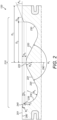
Figure 2 shows a cross-sectional schematic view of the piston ofFigure 1 ; -
Figure 3 shows a cross-sectional schematic view of a first prior art piston bowl, for purposes of comparison; -
Figure 4 shows a cross-sectional schematic view of a second prior art piston bowl, for purposes of comparison; -
Figure 5 shows a cross-sectional schematic view of a first option of a lip geometry of the piston bowl ofFigure 1 that falls within the scope of the claims; -
Figure 6 shows a cross-sectional schematic view of a second option of a lip geometry of the piston bowl ofFigure 1 that does not fall within the scope of the claims; -
Figure 7 shows a cross-sectional schematic view of an injector suitable for use with the piston bowl of the present disclosure; -
Figure 8 provides a graph showing performance of the piston bowl ofFigures 1 and2 versus prior art piston bowls such as those ofFigures 3 and4 ; and -
Figure 9 provides a graph showing performance of the piston bowl ofFigures 1 and2 versus prior art piston bowls such as those ofFigures 3 and4 . -
Figure 1 shows a cross section through acylinder 100 of an internal combustion engine together with related features. The cylinder comprises aninternal bore 101. Theinternal bore 101 accommodates apiston 110. Thepiston 110 is coaxial with theinternal bore 101 of thecylinder 100 such that thepiston 110 is movable relative to thecylinder 100 in an axial direction. - The
cylinder 100 comprises afuel injector 130 located atop end 102 of thecylinder 100. - The
fuel injector 130 may be located coaxially with theinternal bore 101 of the cylinder such that fuel injected by thefuel injector 130 may enter theinternal bore 101 at the axis. Thefuel injector 130 may comprise a fuel injector head (not shown) for distributing fuel in accordance with a desired geometrical arrangement. - The
piston 110 comprises apiston crown 120 and a piston body (not shown but located underneath thepiston crown 120 in the orientation ofFigure 1 ). Thepiston crown 120 is at a head end of thepiston 110 such that thepiston crown 120 of thepiston 110 faces thefuel injector 130. - The
cylinder 100 may further comprise anoxidant inlet 140 for selectively allowing inlet of an oxidant, such as air, to facilitate combustion and anexhaust outlet 150 for selectively allowing release of combustion products from thecylinder 100. Theoxidant inlet 140 and theexhaust outlet 150 may be located at thetop end 102 of thecylinder 100 adjacent thefuel injector 130. - An
intake passage 90 is in fluid communication with, and configured to supply air to,cylinder 100, and anexhaust passage 92 is also in fluid communication with, and conveys combustion products out of,cylinder 100. Intake valves and exhaust valves are not shown inFigure 1 , but will typically be provided in a conventional manner. An exhaustgas recirculation loop 94 may connectpassages recirculation control valve 96 and anexhaust gas cooler 98 positioned therein. - In
Figure 1 , thepiston 110 is shown relative to thecylinder 110 at a position in its oscillating cycle that is closest to thetop end 102 of thecylinder 100. - The
piston crown 120 has an axial direction that sits vertically in the orientation ofFigure 1 and a radial direction that sits horizontally in the orientation ofFigure 1 . Thepiston crown 120 is rotationally symmetrical about acentral axis 290 in the axial direction. Thecentral axis 290 of thepiston crown 120 is, when in situ in the cylinder, coaxial with a central axis of thefuel injector 130. -
Figure 2 shows the piston ofFigure 1 in isolation from thecylinder 100. Referring toFigure 2 , thepiston crown 120 comprises anannular surface 201 at afirst end 280 of thepiston crown 120 in the axial direction that, when in situ in thecylinder 100, faces thefuel injector 130. Theannular surface 201 may be radially furthest from thecentral axis 290. - The
piston crown 120 further comprises apiston bowl 210 located radially within theannular surface 201 and recessed relative to thefirst end 280 of the piston crown. - The
piston bowl 210 comprises a raisedfloor 220 in a radially central region of thepiston bowl 120. Thepiston bowl 210 further comprises anarcuate surface 230 located radially outward relative to the raisedfloor 220. Thepiston bowl 210 further comprises acircumferential surface 235 parallel to the axis of thepiston bowl 210 and located radially outward relative to thearcuate surface 230. Thepiston bowl 210 further comprises alip chamfer surface 240 extending radially outwardly from thecircumferential surface 235 and radially inwardly from theannular surface 201. - The raised
floor 220 comprises a frusto-conical surface 221 tapering in a direction of thefirst end 280 of the piston crown towards aspherical cap 222 that caps the frusto-conical surface 221. An angle of the frusto-conical surface 221 relative to a plane orthogonal to theaxis 290 is the same as an angle of the lowest portion of thespherical cap 222 so as to avoid any surface discontinuity at the interface between the frusto-conical surface 221 and thespherical cap 222. Put another way, a diameter of the frusto-conical surface 221 at its smaller end is the same as a widest dimension of thespherical cap 222. Furthermore, the diameter of the frusto-conical surface 221 is aligned with the widest dimension of thespherical cap 222. - The
arcuate surface 230, when thepiston 120 is viewed in diametric cross section, has a single radius between where thearcuate surface 230 interfaces with a radially outermost end of the frusto-conical surface 221 and where thearcuate surface 230 interfaces with thecircumferential surface 235 parallel to the axis of thepiston bowl 210. - The
lip chamfer surface 240 that extends radially outwardly from thecircumferential surface 235 and radially inwardly from theannular surface 201 tapers such that a widest portion of thepiston bowl 210 is at its entrance. Its entrance is location in a plane shared with theannular surface 201 at the first end of thepiston crown 280. - The
cylinder 100 in which thepiston 120 reciprocates has a radius D1 such that an overall diameter of thecylinder 100 is 2D1. A diameter of a largest part of thepiston 120 is smaller than 2D1. Thecircumferential surface 235 of thepiston 120 has a radius D2 such that the diameter of thecircumferential surface 235 is 2D2. Thelip chamfer surface 240 has a radial dimension D8. In this way, a diameter of the piston bowl throat in the plane of theannular surface 201 is 2(D2 + Ds). A dimension along the axis of the piston between the plane of theannular surface 201 and a part of the spherical cap closest thereto is D5. - An angle between opposing straight line portions (that is, when viewed in diametric cross-section) of the frusto-
conical surface 221 is A1. For comparison purposes, an angle between axes of injector orifices configured to inject fuel into the cylinder is A2. - A radius of curvature between the
annular surface 201 and thelip chamfer surface 240 is R1, and in the claimed embodiments R1 is zero. A radius of curvature between thelip chamfer surface 240 and thecircumferential surface 235 is R2. A radius of curvature of thearcuate surface 230 is R3. A radius of curvature of thespherical cap 222 is R5. - For the avoidance of doubt, the radii of curvature R1, R2, R4 and R5 are those identifiable in diametric cross-section through the axis of the
piston 120. It should be noted that, for clarity, the radii marked on the Figures are drawn to arbitrary lengths and do not relate in any way to the absolute length or to the relative length of the radii they represent. - A dimension in an axial direction between the
annular surface 201 and the origin of the radius R2 is D4. - In a first embodiment, the
lip chamfer surface 240 is a straight line between an inner end of the radii R1 and an outer end of the radii R2, when viewed in diametric cross-section through the axis of thepiston 120. An angle between the straight line of thelip chamber surface 240 and theannular surface 201 is A4. This is shown in more detail inFigure 5 , albeit highly schematically. - In an alternative arrangement falling outside the scope of the claims, the
lip chamfer surface 240 is curved between an inner end of the radii R1 and an outer end of the radii R2, when viewed in diametric cross-section through the axis of thepiston 120. The radius of curvature of thelip chamfer surface 240 in such an arrangement is R6. This is shown inFigure 6 , albeit highly schematically, particularly since R6 may be sufficiently large as not to be immediately identifiable at the scale shown inFigure 6 . An angle between a tangent to the radius R6 and theannular surface 201 is A4 (for clarity, the tangent and angle are not shown inFigure 6 ). - In the case of the
Figure 6 arrangement that falls outside the scope of the claims, the value A4 may be between 19 ° and 21 °. In the case of theFigure 5 embodiment, the value A4 is 20 °. - Some specific exemplary Figures for the parameters described above and identified in the Figures are provided in the table below.
Figures 1 ,2 and5 show embodiments of the present disclosure,Figure 6 shows an arrangement that falls outside the scope of the claims andFigures 3 and4 relate to prior art piston bowls.Figures 1 ,2 ,5 & 6 Figure 3 Figure 4 R1 0 mm n/a n/a R2 1.5 mm 1.5 mm 1.5 mm R3 10.5 mm 12 mm 12 mm R5 10 mm 9.98 mm 10 mm R6 n/a or > 30 mm n/a n/a A1 125.7 degrees 125 degrees 125 degrees A2 130 degrees 130 degrees 130 degrees A2 minus A1 4.3 degrees 5 degrees 5 degrees A4 20 degrees n/a n/a D1 (bore radius) 49 mm 52.5 mm 52.5 mm D2 34.95 mm 38.3 mm 38.3 mm D4 2.49 mm 1.5 mm 1.5 mm D5 3.55 mm 4.81 mm 3.97 mm D8 3.95 mm 0 mm 0 mm Number of injector orifices 6 6 6 Bowl volume 42.1 cm3 58.5 cm3 54.6 cm3 Compression ratio 17.0:1 16.5: 1 16.5:1 Swirl ratio 1.8 0.4 0.6 - In use, fuel is injected into the combustion chamber from an
injector 130 shown inFigures 1 and7 . Theinjector 130 comprises a plurality ofspray discharge orifices 131 through which fuel may be injected. In the claimed embodiment, the number ofspray discharge orifices 131 is six (6). - Each
spray discharge orifice 131 has a central axis Q. Central axis Q passes through the centre point of eachspray discharge orifice 131. In an embodiment, each central axis Q may be transverse to a plane extending across each respectivespray discharge orifice 131. In an embodiment, each spray discharge passage has a longitudinal axis that is coincident with central axis Q of respectivespray discharge orifice 131. Each respective spray discharge passage may extend along the central axis Q. In an embodiment, each central axis Q may be normal to a plane extending across each respective inlet. - Each central axis Q has an angle γ relative to a central axis P of the
injector 130 which is coincident with the central axis of thepiston 290. In some comparative examples, each central axis Q may have an angle γ of approximately 64.5 ° to 65.5 ° relative to the central axis P. According to the claims, each central axis Q has an angle γ of 65 ° relative to the central axis P. Fuel injector 10 has a spray cone angle A2 (seeFigure 1 ) that is defined by angle 2γ (seeFigure 7 ). Accordingly, in the comparative examples, fuel vapour from the plurality ofspray discharge orifices 131 may be discharged with a spray cone angle of approximately 129 ° to 131 °. According to the claims, fuel vapour from the plurality ofspray discharge orifices 131 is discharged with a spray cone angle of 130 °. - Fuel may be discharged from the plurality of
spray discharge orifices 131 at a flow rate of 680 to 720 cc/min. Fuel may be expelled from the plurality ofspray discharge orifices 131 at a flow rate of 700 cc/min. - As mentioned previously, a swirl ratio is defined as angular rotational speed about the cylinder axis. In the claimed embodiment, a swirl ratio of 1.8 is employed. This may promote efficient mixing of the fuel and air and avoid combustion products residing in specific areas that may affect engine durability.
- The
lip chamfer surface 240 may be particularly beneficial in a piston of reduced size since it promotes distribution of fuel leaving the piston bowl. As distinct from the prior art embodiments ofFigures 3 and4 which have larger combustion volumes, thelip chamfer surface 240 of the embodiments of the present disclosure may encourage improved fuel distribution for improved thermal distribution and improved combustion efficiency, perhaps most particularly applicable in a combustion cylinder operating a fuel injector with a swirl ratio of approximately 1.8. -
Figure 8 provides a plot of soot against NOx for piston bowls in accordance with the disclosure (e.g.Figures 1 and2 ) relative to piston bowls of the prior art (e.g.Figures 3 and4 ). As can be seen, the piston bowl of the present disclosure provides lower soot than the piston bowl of the prior art, when using the same swirl ratio. -
Figure 9 provides a plot of flux versus injection timing and shows plots both for piston bowls in accordance with the prior art (e.g.Figures 3 and4 ) and piston bowls of the present disclosure (e.g.Figures 1 and2 ). - The present disclosure relates to a spray guided piston bowl that may be applicable to a diesel engine for achieving improved fuel to air mixing that in turn results in more efficient combustion and reduced NOx and/or particulate emissions.
- The piston may be of aluminium. The engine may be based on a known larger engine with a reduced piston diameter and volume and adapted to improve efficiency and to target specific emissions outputs.
Claims (4)
- A combustion cylinder (100) of an internal combustion engine, configured to provide a swirl ratio of 1.8, the combustion cylinder (100) comprising:a fuel injector (130) having 6 fuel spray discharge orifices arranged so as to provide a fuel injection cone angle of 130 degrees; anda piston (110) having a piston crown (120), the piston (110) having a diameter of 98 mm, and,the piston crown (120) extending in an axial direction along a central axis (290) and in a radial direction outwardly from the central axis (290), the piston crown (120) comprising: an annular surface (201) at a first end (280) of the piston crown (120) in the axial direction; and a piston bowl (210) located radially within the annular surface (201) and recessed relative to the first end (280) of the piston crown (120); wherein the piston bowl (210) comprises:a raised floor (220) having an axis of rotation (290) coincident with the central axis (290) of the piston crown (120), the raised floor (220) comprising a frusto-conical portion (221) tapering in a direction of the first end (280) of the piston crown (120) towards a spherical cap portion (222) capping the frusto-conical portion (221);an arcuate surface (230) located radially outward relative to the raised floor (220);a circumferential surface (235) parallel to the central axis (290) of the piston bowl (210) at a radially outward end of the arcuate surface (230); anda lip chamfer surface (240) extending radially outwardly from the circumferential surface (235) and radially inwardly from the annular surface (201) and tapering away from the first end (280) of the piston crown (120);wherein in diametric cross-section the lip chamfer surface (240) is a straight line;wherein the diameter of the circumferential surface (235) is 69.9 mm;wherein a radius of curvature between the annular surface (201) and the lip chamfer surface (240) is 0 mm;wherein a radius of curvature between the lip chamfer surface (240) and the circumferential surface (235) is 1.5 mm;wherein in diametric cross-section the arcuate surface (230) comprises a circular arc having a radius of 10.5 mm;wherein a radius of curvature of the spherical cap portion (222) is 10 mm;wherein an angle between opposing straight line portions of the frusto-conical portion (221) is 125.7 degrees;wherein an angle between the lip chamfer surface (240) and the annular surface (201) is 20 degrees;wherein a dimension in the axial direction measured from the annular surface (201) to an origin of the radius of curvature between the circumferential surface (235) and the lip chamfer surface (240) is 2.49 mm;wherein a dimension along the central axis (290) between the plane of the annular surface (201) and a part of the spherical cap closest thereto is 3.55 mm;wherein lip chamfer surface (240) extends 3.95 mm in a radial dimension;wherein the piston bowl (210) has a volume of 42.1 cm3; andwherein the combustion cylinder has a compression ratio of 17.0:1.
- The combustion cylinder (100) of claim 1 wherein the fuel injector (130) is mounted at an end of the combustion cylinder (120) facing the piston crown (120).
- The combustion cylinder (100) of any preceding claim wherein a difference between the fuel injection cone angle and an angle between opposing sides of the frusto-conical portion is 4.3 °.
- An internal combustion engine comprising the combustion cylinder (100) of any preceding claim and an intake valve and an exhaust valve.
Applications Claiming Priority (2)
| Application Number | Priority Date | Filing Date | Title |
|---|---|---|---|
| GB1620510.6A GB2557267B (en) | 2016-12-02 | 2016-12-02 | Piston crown with swirl-inducing bowl |
| PCT/EP2017/080572 WO2018099875A1 (en) | 2016-12-02 | 2017-11-27 | Piston crown |
Publications (2)
| Publication Number | Publication Date |
|---|---|
| EP3548725A1 EP3548725A1 (en) | 2019-10-09 |
| EP3548725B1 true EP3548725B1 (en) | 2024-01-03 |
Family
ID=58159812
Family Applications (1)
| Application Number | Title | Priority Date | Filing Date |
|---|---|---|---|
| EP17804552.2A Active EP3548725B1 (en) | 2016-12-02 | 2017-11-27 | Combustion cylinder |
Country Status (6)
| Country | Link |
|---|---|
| US (1) | US20190292978A1 (en) |
| EP (1) | EP3548725B1 (en) |
| JP (1) | JP7271420B2 (en) |
| CN (1) | CN109996942A (en) |
| GB (1) | GB2557267B (en) |
| WO (1) | WO2018099875A1 (en) |
Families Citing this family (4)
| Publication number | Priority date | Publication date | Assignee | Title |
|---|---|---|---|---|
| US11608804B1 (en) | 2021-08-25 | 2023-03-21 | Caterpillar Inc. | Fuel injector having side-fitted fuel connector for tight packaging in top-feed fuel system |
| US11603817B1 (en) | 2021-08-25 | 2023-03-14 | Caterpillar Inc. | Slim-profile fuel injector for tight packaging in top feed fuel system |
| US11644000B2 (en) | 2021-08-25 | 2023-05-09 | Caterpillar Inc. | Fuel injector clamp assembly for offset clamping bolt and cylinder head assembly with same |
| US11898516B2 (en) | 2021-08-25 | 2024-02-13 | Caterpillar Inc. | Cylinder head having bore locations arranged for tight packaging of gas exchange and fuel system components |
Family Cites Families (13)
| Publication number | Priority date | Publication date | Assignee | Title |
|---|---|---|---|---|
| US5322042A (en) * | 1992-06-17 | 1994-06-21 | Sonex Research, Inc. | Combustion chamber for internal combustion engine and process of combustion using fuel radical species |
| JP3751462B2 (en) * | 1998-03-27 | 2006-03-01 | 株式会社豊田中央研究所 | Direct injection diesel engine |
| JP2002155747A (en) * | 2000-11-21 | 2002-05-31 | Toyota Motor Corp | Internal combustion engine piston |
| US7210448B2 (en) * | 2002-06-11 | 2007-05-01 | Cummins, Inc. | Internal combustion engine producing low emissions |
| JP2007239627A (en) | 2006-03-09 | 2007-09-20 | Nissan Motor Co Ltd | Spark ignition internal combustion engine |
| FR2925603A1 (en) * | 2007-12-19 | 2009-06-26 | Renault Sas | COMBUSTION CHAMBER FOR SUPERIOR THERMAL MOTOR WITH DIRECT INJECTION |
| FR2925604A1 (en) * | 2007-12-19 | 2009-06-26 | Renault Sas | COMBUSTION CHAMBER FOR THERMAL MOTOR WITH DIRECT OVERFLOW INJECTION |
| JP5272611B2 (en) | 2008-09-25 | 2013-08-28 | マツダ株式会社 | Spark ignition internal combustion engine |
| US8544445B2 (en) | 2010-03-09 | 2013-10-01 | Pinnacle Engines, Inc. | Over-compressed engine |
| US8978621B2 (en) | 2010-04-20 | 2015-03-17 | Caterpillar Inc. | Piston having combustion bowl shaped to balance combustion efficiency and emission properties |
| US9234451B2 (en) * | 2010-04-20 | 2016-01-12 | Caterpillar Inc. | Piston having combustion bowl shaped to balance combustion efficiency and emission properties |
| WO2014151916A1 (en) | 2013-03-15 | 2014-09-25 | Achates Power, Inc. | Piston crown bowls defining combustion chamber constructions in opposed-piston engines |
| US9328693B2 (en) * | 2013-07-17 | 2016-05-03 | Electro-Motive Diesel, Inc. | Piston, engine and operating method for reduced production of particulate matter |
-
2016
- 2016-12-02 GB GB1620510.6A patent/GB2557267B/en active Active
-
2017
- 2017-11-27 EP EP17804552.2A patent/EP3548725B1/en active Active
- 2017-11-27 US US16/348,773 patent/US20190292978A1/en not_active Abandoned
- 2017-11-27 JP JP2019527919A patent/JP7271420B2/en active Active
- 2017-11-27 WO PCT/EP2017/080572 patent/WO2018099875A1/en not_active Ceased
- 2017-11-27 CN CN201780073189.9A patent/CN109996942A/en active Pending
Also Published As
| Publication number | Publication date |
|---|---|
| GB201620510D0 (en) | 2017-01-18 |
| JP2020501067A (en) | 2020-01-16 |
| GB2557267A (en) | 2018-06-20 |
| CN109996942A (en) | 2019-07-09 |
| WO2018099875A1 (en) | 2018-06-07 |
| JP7271420B2 (en) | 2023-05-11 |
| GB2557267B (en) | 2020-05-06 |
| EP3548725A1 (en) | 2019-10-09 |
| US20190292978A1 (en) | 2019-09-26 |
Similar Documents
| Publication | Publication Date | Title |
|---|---|---|
| JP6215943B2 (en) | Diesel engine combustion chamber structure | |
| US8677974B2 (en) | Piston bowl with flat bottom | |
| EP2516833B1 (en) | Piston for an internal combustion engine | |
| EP3548725B1 (en) | Combustion cylinder | |
| EP2997245B1 (en) | Piston having combustion bowl and engine using same | |
| US8683974B2 (en) | Piston | |
| US20150020765A1 (en) | Combustion bowl of piston | |
| JP2019503451A (en) | Variable compression ratio internal combustion engine with two mixing zones, in particular for motor vehicles, and injection method for such vehicles | |
| CN102985658A (en) | Self-igniting internal combustion engine having piston recesses having swirl steps | |
| WO2014188736A1 (en) | Direct injection diesel engine | |
| EP2752564A1 (en) | Piston | |
| US20150020766A1 (en) | Prechamber device for an internal combustion engine | |
| EP3176402B1 (en) | Piston for a gaseous fuel internal combustion engine | |
| GB2557266A (en) | Piston bowl | |
| JP2017025929A (en) | Combustion chamber structure of diesel engine | |
| US11319867B2 (en) | Piston bowl for an internal combustion engine | |
| US8833327B2 (en) | Piston and combustion chamber | |
| US11230992B2 (en) | Piston geometry for reduced smoke and cylinder head component temperatures | |
| US12264636B2 (en) | Low compression natural gas engine piston bowl for improved combustion stability | |
| CN102062014A (en) | Combustion chamber of diesel engine |
Legal Events
| Date | Code | Title | Description |
|---|---|---|---|
| STAA | Information on the status of an ep patent application or granted ep patent |
Free format text: STATUS: UNKNOWN |
|
| STAA | Information on the status of an ep patent application or granted ep patent |
Free format text: STATUS: THE INTERNATIONAL PUBLICATION HAS BEEN MADE |
|
| PUAI | Public reference made under article 153(3) epc to a published international application that has entered the european phase |
Free format text: ORIGINAL CODE: 0009012 |
|
| STAA | Information on the status of an ep patent application or granted ep patent |
Free format text: STATUS: REQUEST FOR EXAMINATION WAS MADE |
|
| 17P | Request for examination filed |
Effective date: 20190701 |
|
| AK | Designated contracting states |
Kind code of ref document: A1 Designated state(s): AL AT BE BG CH CY CZ DE DK EE ES FI FR GB GR HR HU IE IS IT LI LT LU LV MC MK MT NL NO PL PT RO RS SE SI SK SM TR |
|
| AX | Request for extension of the european patent |
Extension state: BA ME |
|
| DAV | Request for validation of the european patent (deleted) | ||
| DAX | Request for extension of the european patent (deleted) | ||
| STAA | Information on the status of an ep patent application or granted ep patent |
Free format text: STATUS: EXAMINATION IS IN PROGRESS |
|
| 17Q | First examination report despatched |
Effective date: 20210129 |
|
| GRAP | Despatch of communication of intention to grant a patent |
Free format text: ORIGINAL CODE: EPIDOSNIGR1 |
|
| STAA | Information on the status of an ep patent application or granted ep patent |
Free format text: STATUS: GRANT OF PATENT IS INTENDED |
|
| INTG | Intention to grant announced |
Effective date: 20230807 |
|
| GRAS | Grant fee paid |
Free format text: ORIGINAL CODE: EPIDOSNIGR3 |
|
| P01 | Opt-out of the competence of the unified patent court (upc) registered |
Effective date: 20231020 |
|
| GRAA | (expected) grant |
Free format text: ORIGINAL CODE: 0009210 |
|
| STAA | Information on the status of an ep patent application or granted ep patent |
Free format text: STATUS: THE PATENT HAS BEEN GRANTED |
|
| AK | Designated contracting states |
Kind code of ref document: B1 Designated state(s): AL AT BE BG CH CY CZ DE DK EE ES FI FR GB GR HR HU IE IS IT LI LT LU LV MC MK MT NL NO PL PT RO RS SE SI SK SM TR |
|
| REG | Reference to a national code |
Ref country code: GB Ref legal event code: FG4D |
|
| REG | Reference to a national code |
Ref country code: CH Ref legal event code: EP |
|
| REG | Reference to a national code |
Ref country code: DE Ref legal event code: R096 Ref document number: 602017078157 Country of ref document: DE |
|
| REG | Reference to a national code |
Ref country code: IE Ref legal event code: FG4D |
|
| REG | Reference to a national code |
Ref country code: LT Ref legal event code: MG9D |
|
| PG25 | Lapsed in a contracting state [announced via postgrant information from national office to epo] |
Ref country code: ES Free format text: LAPSE BECAUSE OF FAILURE TO SUBMIT A TRANSLATION OF THE DESCRIPTION OR TO PAY THE FEE WITHIN THE PRESCRIBED TIME-LIMIT Effective date: 20240103 |
|
| PG25 | Lapsed in a contracting state [announced via postgrant information from national office to epo] |
Ref country code: ES Free format text: LAPSE BECAUSE OF FAILURE TO SUBMIT A TRANSLATION OF THE DESCRIPTION OR TO PAY THE FEE WITHIN THE PRESCRIBED TIME-LIMIT Effective date: 20240103 |
|
| REG | Reference to a national code |
Ref country code: NL Ref legal event code: MP Effective date: 20240103 |
|
| REG | Reference to a national code |
Ref country code: AT Ref legal event code: MK05 Ref document number: 1647013 Country of ref document: AT Kind code of ref document: T Effective date: 20240103 |
|
| PG25 | Lapsed in a contracting state [announced via postgrant information from national office to epo] |
Ref country code: NL Free format text: LAPSE BECAUSE OF FAILURE TO SUBMIT A TRANSLATION OF THE DESCRIPTION OR TO PAY THE FEE WITHIN THE PRESCRIBED TIME-LIMIT Effective date: 20240103 |
|
| PG25 | Lapsed in a contracting state [announced via postgrant information from national office to epo] |
Ref country code: NL Free format text: LAPSE BECAUSE OF FAILURE TO SUBMIT A TRANSLATION OF THE DESCRIPTION OR TO PAY THE FEE WITHIN THE PRESCRIBED TIME-LIMIT Effective date: 20240103 |
|
| PG25 | Lapsed in a contracting state [announced via postgrant information from national office to epo] |
Ref country code: IS Free format text: LAPSE BECAUSE OF FAILURE TO SUBMIT A TRANSLATION OF THE DESCRIPTION OR TO PAY THE FEE WITHIN THE PRESCRIBED TIME-LIMIT Effective date: 20240503 |
|
| PG25 | Lapsed in a contracting state [announced via postgrant information from national office to epo] |
Ref country code: LT Free format text: LAPSE BECAUSE OF FAILURE TO SUBMIT A TRANSLATION OF THE DESCRIPTION OR TO PAY THE FEE WITHIN THE PRESCRIBED TIME-LIMIT Effective date: 20240103 |
|
| PG25 | Lapsed in a contracting state [announced via postgrant information from national office to epo] |
Ref country code: GR Free format text: LAPSE BECAUSE OF FAILURE TO SUBMIT A TRANSLATION OF THE DESCRIPTION OR TO PAY THE FEE WITHIN THE PRESCRIBED TIME-LIMIT Effective date: 20240404 |
|
| PG25 | Lapsed in a contracting state [announced via postgrant information from national office to epo] |
Ref country code: HR Free format text: LAPSE BECAUSE OF FAILURE TO SUBMIT A TRANSLATION OF THE DESCRIPTION OR TO PAY THE FEE WITHIN THE PRESCRIBED TIME-LIMIT Effective date: 20240103 Ref country code: RS Free format text: LAPSE BECAUSE OF FAILURE TO SUBMIT A TRANSLATION OF THE DESCRIPTION OR TO PAY THE FEE WITHIN THE PRESCRIBED TIME-LIMIT Effective date: 20240403 |
|
| PG25 | Lapsed in a contracting state [announced via postgrant information from national office to epo] |
Ref country code: CZ Free format text: LAPSE BECAUSE OF FAILURE TO SUBMIT A TRANSLATION OF THE DESCRIPTION OR TO PAY THE FEE WITHIN THE PRESCRIBED TIME-LIMIT Effective date: 20240103 Ref country code: AT Free format text: LAPSE BECAUSE OF FAILURE TO SUBMIT A TRANSLATION OF THE DESCRIPTION OR TO PAY THE FEE WITHIN THE PRESCRIBED TIME-LIMIT Effective date: 20240103 |
|
| PG25 | Lapsed in a contracting state [announced via postgrant information from national office to epo] |
Ref country code: RS Free format text: LAPSE BECAUSE OF FAILURE TO SUBMIT A TRANSLATION OF THE DESCRIPTION OR TO PAY THE FEE WITHIN THE PRESCRIBED TIME-LIMIT Effective date: 20240403 Ref country code: NO Free format text: LAPSE BECAUSE OF FAILURE TO SUBMIT A TRANSLATION OF THE DESCRIPTION OR TO PAY THE FEE WITHIN THE PRESCRIBED TIME-LIMIT Effective date: 20240403 Ref country code: LT Free format text: LAPSE BECAUSE OF FAILURE TO SUBMIT A TRANSLATION OF THE DESCRIPTION OR TO PAY THE FEE WITHIN THE PRESCRIBED TIME-LIMIT Effective date: 20240103 Ref country code: IS Free format text: LAPSE BECAUSE OF FAILURE TO SUBMIT A TRANSLATION OF THE DESCRIPTION OR TO PAY THE FEE WITHIN THE PRESCRIBED TIME-LIMIT Effective date: 20240503 Ref country code: HR Free format text: LAPSE BECAUSE OF FAILURE TO SUBMIT A TRANSLATION OF THE DESCRIPTION OR TO PAY THE FEE WITHIN THE PRESCRIBED TIME-LIMIT Effective date: 20240103 Ref country code: GR Free format text: LAPSE BECAUSE OF FAILURE TO SUBMIT A TRANSLATION OF THE DESCRIPTION OR TO PAY THE FEE WITHIN THE PRESCRIBED TIME-LIMIT Effective date: 20240404 Ref country code: CZ Free format text: LAPSE BECAUSE OF FAILURE TO SUBMIT A TRANSLATION OF THE DESCRIPTION OR TO PAY THE FEE WITHIN THE PRESCRIBED TIME-LIMIT Effective date: 20240103 Ref country code: BG Free format text: LAPSE BECAUSE OF FAILURE TO SUBMIT A TRANSLATION OF THE DESCRIPTION OR TO PAY THE FEE WITHIN THE PRESCRIBED TIME-LIMIT Effective date: 20240103 Ref country code: AT Free format text: LAPSE BECAUSE OF FAILURE TO SUBMIT A TRANSLATION OF THE DESCRIPTION OR TO PAY THE FEE WITHIN THE PRESCRIBED TIME-LIMIT Effective date: 20240103 |
|
| PG25 | Lapsed in a contracting state [announced via postgrant information from national office to epo] |
Ref country code: PT Free format text: LAPSE BECAUSE OF FAILURE TO SUBMIT A TRANSLATION OF THE DESCRIPTION OR TO PAY THE FEE WITHIN THE PRESCRIBED TIME-LIMIT Effective date: 20240503 Ref country code: PL Free format text: LAPSE BECAUSE OF FAILURE TO SUBMIT A TRANSLATION OF THE DESCRIPTION OR TO PAY THE FEE WITHIN THE PRESCRIBED TIME-LIMIT Effective date: 20240103 |
|
| PG25 | Lapsed in a contracting state [announced via postgrant information from national office to epo] |
Ref country code: SE Free format text: LAPSE BECAUSE OF FAILURE TO SUBMIT A TRANSLATION OF THE DESCRIPTION OR TO PAY THE FEE WITHIN THE PRESCRIBED TIME-LIMIT Effective date: 20240103 Ref country code: PT Free format text: LAPSE BECAUSE OF FAILURE TO SUBMIT A TRANSLATION OF THE DESCRIPTION OR TO PAY THE FEE WITHIN THE PRESCRIBED TIME-LIMIT Effective date: 20240503 Ref country code: PL Free format text: LAPSE BECAUSE OF FAILURE TO SUBMIT A TRANSLATION OF THE DESCRIPTION OR TO PAY THE FEE WITHIN THE PRESCRIBED TIME-LIMIT Effective date: 20240103 Ref country code: LV Free format text: LAPSE BECAUSE OF FAILURE TO SUBMIT A TRANSLATION OF THE DESCRIPTION OR TO PAY THE FEE WITHIN THE PRESCRIBED TIME-LIMIT Effective date: 20240103 |
|
| REG | Reference to a national code |
Ref country code: DE Ref legal event code: R097 Ref document number: 602017078157 Country of ref document: DE |
|
| PG25 | Lapsed in a contracting state [announced via postgrant information from national office to epo] |
Ref country code: DK Free format text: LAPSE BECAUSE OF FAILURE TO SUBMIT A TRANSLATION OF THE DESCRIPTION OR TO PAY THE FEE WITHIN THE PRESCRIBED TIME-LIMIT Effective date: 20240103 |
|
| PG25 | Lapsed in a contracting state [announced via postgrant information from national office to epo] |
Ref country code: SM Free format text: LAPSE BECAUSE OF FAILURE TO SUBMIT A TRANSLATION OF THE DESCRIPTION OR TO PAY THE FEE WITHIN THE PRESCRIBED TIME-LIMIT Effective date: 20240103 |
|
| PG25 | Lapsed in a contracting state [announced via postgrant information from national office to epo] |
Ref country code: EE Free format text: LAPSE BECAUSE OF FAILURE TO SUBMIT A TRANSLATION OF THE DESCRIPTION OR TO PAY THE FEE WITHIN THE PRESCRIBED TIME-LIMIT Effective date: 20240103 |
|
| PG25 | Lapsed in a contracting state [announced via postgrant information from national office to epo] |
Ref country code: SK Free format text: LAPSE BECAUSE OF FAILURE TO SUBMIT A TRANSLATION OF THE DESCRIPTION OR TO PAY THE FEE WITHIN THE PRESCRIBED TIME-LIMIT Effective date: 20240103 |
|
| PG25 | Lapsed in a contracting state [announced via postgrant information from national office to epo] |
Ref country code: SM Free format text: LAPSE BECAUSE OF FAILURE TO SUBMIT A TRANSLATION OF THE DESCRIPTION OR TO PAY THE FEE WITHIN THE PRESCRIBED TIME-LIMIT Effective date: 20240103 Ref country code: SK Free format text: LAPSE BECAUSE OF FAILURE TO SUBMIT A TRANSLATION OF THE DESCRIPTION OR TO PAY THE FEE WITHIN THE PRESCRIBED TIME-LIMIT Effective date: 20240103 Ref country code: RO Free format text: LAPSE BECAUSE OF FAILURE TO SUBMIT A TRANSLATION OF THE DESCRIPTION OR TO PAY THE FEE WITHIN THE PRESCRIBED TIME-LIMIT Effective date: 20240103 Ref country code: EE Free format text: LAPSE BECAUSE OF FAILURE TO SUBMIT A TRANSLATION OF THE DESCRIPTION OR TO PAY THE FEE WITHIN THE PRESCRIBED TIME-LIMIT Effective date: 20240103 Ref country code: DK Free format text: LAPSE BECAUSE OF FAILURE TO SUBMIT A TRANSLATION OF THE DESCRIPTION OR TO PAY THE FEE WITHIN THE PRESCRIBED TIME-LIMIT Effective date: 20240103 |
|
| PLBE | No opposition filed within time limit |
Free format text: ORIGINAL CODE: 0009261 |
|
| STAA | Information on the status of an ep patent application or granted ep patent |
Free format text: STATUS: NO OPPOSITION FILED WITHIN TIME LIMIT |
|
| PG25 | Lapsed in a contracting state [announced via postgrant information from national office to epo] |
Ref country code: IT Free format text: LAPSE BECAUSE OF FAILURE TO SUBMIT A TRANSLATION OF THE DESCRIPTION OR TO PAY THE FEE WITHIN THE PRESCRIBED TIME-LIMIT Effective date: 20240103 |
|
| 26N | No opposition filed |
Effective date: 20241007 |
|
| PG25 | Lapsed in a contracting state [announced via postgrant information from national office to epo] |
Ref country code: IT Free format text: LAPSE BECAUSE OF FAILURE TO SUBMIT A TRANSLATION OF THE DESCRIPTION OR TO PAY THE FEE WITHIN THE PRESCRIBED TIME-LIMIT Effective date: 20240103 |
|
| PG25 | Lapsed in a contracting state [announced via postgrant information from national office to epo] |
Ref country code: SI Free format text: LAPSE BECAUSE OF FAILURE TO SUBMIT A TRANSLATION OF THE DESCRIPTION OR TO PAY THE FEE WITHIN THE PRESCRIBED TIME-LIMIT Effective date: 20240103 |
|
| REG | Reference to a national code |
Ref country code: CH Ref legal event code: PL |
|
| PG25 | Lapsed in a contracting state [announced via postgrant information from national office to epo] |
Ref country code: MC Free format text: LAPSE BECAUSE OF FAILURE TO SUBMIT A TRANSLATION OF THE DESCRIPTION OR TO PAY THE FEE WITHIN THE PRESCRIBED TIME-LIMIT Effective date: 20240103 |
|
| PG25 | Lapsed in a contracting state [announced via postgrant information from national office to epo] |
Ref country code: LU Free format text: LAPSE BECAUSE OF NON-PAYMENT OF DUE FEES Effective date: 20241127 |
|
| REG | Reference to a national code |
Ref country code: CH Ref legal event code: PL |
|
| PG25 | Lapsed in a contracting state [announced via postgrant information from national office to epo] |
Ref country code: CH Free format text: LAPSE BECAUSE OF NON-PAYMENT OF DUE FEES Effective date: 20241130 |
|
| REG | Reference to a national code |
Ref country code: BE Ref legal event code: MM Effective date: 20241130 |
|
| PG25 | Lapsed in a contracting state [announced via postgrant information from national office to epo] |
Ref country code: FI Free format text: LAPSE BECAUSE OF FAILURE TO SUBMIT A TRANSLATION OF THE DESCRIPTION OR TO PAY THE FEE WITHIN THE PRESCRIBED TIME-LIMIT Effective date: 20240103 |
|
| PG25 | Lapsed in a contracting state [announced via postgrant information from national office to epo] |
Ref country code: BE Free format text: LAPSE BECAUSE OF NON-PAYMENT OF DUE FEES Effective date: 20241130 |
|
| PG25 | Lapsed in a contracting state [announced via postgrant information from national office to epo] |
Ref country code: FR Free format text: LAPSE BECAUSE OF NON-PAYMENT OF DUE FEES Effective date: 20241130 |
|
| PG25 | Lapsed in a contracting state [announced via postgrant information from national office to epo] |
Ref country code: IE Free format text: LAPSE BECAUSE OF NON-PAYMENT OF DUE FEES Effective date: 20241127 |
|
| PGFP | Annual fee paid to national office [announced via postgrant information from national office to epo] |
Ref country code: DE Payment date: 20251022 Year of fee payment: 9 |
|
| PGFP | Annual fee paid to national office [announced via postgrant information from national office to epo] |
Ref country code: GB Payment date: 20251023 Year of fee payment: 9 |
|
| PGFP | Annual fee paid to national office [announced via postgrant information from national office to epo] |
Ref country code: TR Payment date: 20251031 Year of fee payment: 9 |
|
| PG25 | Lapsed in a contracting state [announced via postgrant information from national office to epo] |
Ref country code: HU Free format text: LAPSE BECAUSE OF FAILURE TO SUBMIT A TRANSLATION OF THE DESCRIPTION OR TO PAY THE FEE WITHIN THE PRESCRIBED TIME-LIMIT; INVALID AB INITIO Effective date: 20171127 |
|
| PG25 | Lapsed in a contracting state [announced via postgrant information from national office to epo] |
Ref country code: CY Free format text: LAPSE BECAUSE OF FAILURE TO SUBMIT A TRANSLATION OF THE DESCRIPTION OR TO PAY THE FEE WITHIN THE PRESCRIBED TIME-LIMIT; INVALID AB INITIO Effective date: 20171127 |